construction of road under bridge using box pushing …
TRANSCRIPT
International Research Journal of Engineering and Technology (IRJET) e-ISSN: 2395-0056
Volume: 08 Issue: 03 | Mar 2021 www.irjet.net p-ISSN: 2395-0072
© 2021, IRJET | Impact Factor value: 7.529 | ISO 9001:2008 Certified Journal | Page 796
CONSTRUCTION OF ROAD UNDER BRIDGE USING BOX PUSHING
TECHNOLOGY
Anushree M1, Bharath R2, Chandandev N3, Navya Shree M C4, Bhavyashree B N5
1234UG student, Dept. of Civil Engineering, Maharaja Institute Of Technology Mysore, Karnataka, India 5Assistant Professor, Dept. of Civil Engineering, Maharaja Institute Of Technology Mysore, Karnataka, India
---------------------------------------------------------------------***---------------------------------------------------------------------
Abstract - In general intersection of road level and railway track at the same level is referred as level crossing. Usually in urban areas the level crossings are looked after by highly trained professionals to monitor the train movements and close the railway gates. By doing so the traffic congestion appears and lead to loss of time. The solution for this kind of problem is to implement road under bridge technique. Further in this we have discussed about the methodology and problems faced during the process.
Key Words: Problems, methodology, solution, materials
1.INTRODUCTION Level crossings continue to be the weakest point, most unsafe, and source of accidents. Due to increase in train speed and non-observance of rules by road users, these are more critical. Although, the total number of accidents occurring on the Indian railways is showing a progressive decline, level crossing accidents are still hovering at around the same level. To reduce this one of the following three methods are used:
1. Cut and cover method 2. Box pushing method 3. Restricted height girder method
In this we will discuss about Box Pushing Technology. Nowadays box pushing technology is mostly used when
compared to other methods. This method is used as it is safe
for construction in major traffic areas and busy junctions. In
this technique, RCC boxes separated in segments are cast
outside and pushed through heavy embankments of rail or
road by jacking system. The thrust bed is prepared along with
line and level of precast boxes. Later by applying hydraulic
force these RCC box segments are pushed into the
embankment and as the land available is less in cities these
box segments are used as it acquires less space for
construction. Therefore, establishing of this method is a good
option where there is less land or space for constructing
underpass.
1.1 The Technique
This method consists of constructing thrust bed. Then precast RCC box segments are placed over the thrust bed.
Using front cutting shield it excavates the soil and jacking system is used to push the box segments in position. The box segments are constructed and designed cast in-situ. It usually takes 21 to cast one RCC box segment.
1.2 Level Crossing In Indian Railways Indian railways is one of the largest railway network in and around the world. The railway system is fully governed by the Indian government. Approximately there are 31854 level crossings in Indian railways. In this 18321 are manned level crossings and 13533 are unmanned level crossings. Looking into safety aspects Indian government tried eliminating unmanned crossings so that many accidents can be avoided and even the maintenance and repair cost can be reduced.
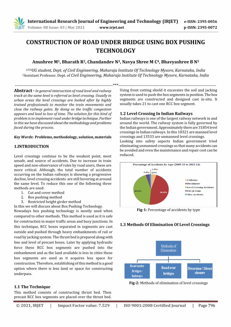
Fig-1: Percentage of accidents by type
1.3 Methods Of Elimination Of Level Crossings
Fig-2: Methods of elimination of level crossings

International Research Journal of Engineering and Technology (IRJET) e-ISSN: 2395-0056
Volume: 08 Issue: 03 | Mar 2021 www.irjet.net p-ISSN: 2395-0072
© 2021, IRJET | Impact Factor value: 7.529 | ISO 9001:2008 Certified Journal | Page 797
1.3.1 Road Under Bridges
The flow of traffic in both perpendicular directions which is
above and below is said to be road under bridge.
Fig-3: Road under bridge
1.3.2 Road Over Bridges
A bridge is structure which is built across the body of valley, water etc. for the free flow to traffic so that the obstruction can be avoided.
Fig-4: Road over bridges
2. STEPS TO BE FOLLOWED IN BOX JACKING
1. Looking toward the backstop launch the slab 2. Slab should be launched looking at the portal wall 3. The launch slab should be greased 4. Piping for passing slurry should be given and rebar
in baox walls 5. Roof casting 6. Shield should be brought to ground 7. Thrust columns should be added after jacking
process 8. Mucking tunnel 9. Process of jacking completes
3. METHODOLOGY FOR BOX PUSHING METHOD
Fig-5: Excavation process
Excavation
Construction of
thrust bed
Casting of RCC
block segments
Pushing of box
segments

International Research Journal of Engineering and Technology (IRJET) e-ISSN: 2395-0056
Volume: 08 Issue: 03 | Mar 2021 www.irjet.net p-ISSN: 2395-0072
© 2021, IRJET | Impact Factor value: 7.529 | ISO 9001:2008 Certified Journal | Page 798
Fig-6: Construction of thrust bed
Fig-7: Casting of RCC box segments
Fig-8: Pushing box segments using hydraulic jack
4. BOX PUSHING OPERATION
1. The box pushing depends on the thrust bed reaction. The thrust bed having screed is dismantled first in the pin pockets, pin pockets are thoroughly cleaned and later the pins are installed in position.
2. The hydraulic jacks are placed between the pins and bottom slab of the leading box segment with spacers and the packing plates.
3. To avoid severe damage to the concrete structure a 20mm thick plate is provided and butted against the slab bottom.
4. 25mm HYSD rods of 12mt length having spacing of 500mm is inserted into soil so that it can prevent caving of earth.
5. For every push of 200mm jacks are released and again packed with spacers and packing plates.
6. Then the second box segment is brought in position behind the first box segment.
7. Hydraulic jacks (10nos.) each of 300 tons are mounted between first and second segments and along with this 4nos. hydraulic jacks of 300 tons each are placed in prior between thrust bed and the second segment.
8. These 4nos. hydraulic jacks of each 300 tons are placed in two slots on either side of the wall to know the correction of line and the level of the box segment while pushing is carried out.
9. The leftover or remains of earth in front of first segment is carved away during pushing and nails are inserted further to strength the embankment.
10. After succeeding the pushing of first segment the second segment is pushed and so on with later boxes.
11. The same procedure is followed for placing each and every segments in position.
12. The segments which are drifted away from the line is brought to the line of segment of box pushing.
13. The procedure is carried out till the first box segment is placed in position.
14. The corners of the boxes are filled with concrete.
5. MATERIALS USED 5.1 Thrust Bed
Fig-9: Thrust bed

International Research Journal of Engineering and Technology (IRJET) e-ISSN: 2395-0056
Volume: 08 Issue: 03 | Mar 2021 www.irjet.net p-ISSN: 2395-0072
© 2021, IRJET | Impact Factor value: 7.529 | ISO 9001:2008 Certified Journal | Page 799
5.2 Front Shield
Fig-10: Front shield
5.3 Rear Shield
Fig-11: Rear shield
5.4 Drag Sheets/Epoxy Coating The upper portion of the box is filled with epoxy coating so that it reduces friction between box and the soil. 5.5 Jacking Operation Jacking system is used to push the box segments and keep the segments in proper alignment. 5.6 Plumb Bob
Fig-12: Plumb bob
5.7 Pistons It is a cylindrical machine which is used to push the constructed box to its position in road under bridge. The pressure which is applied to push the box is of 400 KN to 600 KN. 5.8 Pockets
Fig-13: Pockets in box pushing technology
5.9 Counter Box It is an iron rectangular box on 70cm height and 800 kgs of weight. Counter box is placed in pocket and acts as the support of piston. 5.10 Biscate These biscates are usually placed in the front of piston which helps to push the box segments.
6. PRACTICAL PROBLEMS ENCOUNTERED IN BOX PUSHING TECHNOLOGY At the time of box pushing usually many problems occur in the site for the engineers. The senior authority should act immediately to prevent further problems. Below are few of the problems encountered during the process of box pushing:
1. The tilting of box segments 2. Longitudinal alignment shifting 3. Hard rock occurrence 4. Track geometry disturbance 5. Leak in joints 6. Phenomenon of boulder layer 7. Occurrence of collapsible strata 8. Occurrence floods during box pushing 9. Failure of pin pocket

International Research Journal of Engineering and Technology (IRJET) e-ISSN: 2395-0056
Volume: 08 Issue: 03 | Mar 2021 www.irjet.net p-ISSN: 2395-0072
© 2021, IRJET | Impact Factor value: 7.529 | ISO 9001:2008 Certified Journal | Page 800
7. PRECAUTIONARY MEASURES FOR SUCCESSFUL OPERATION The boxes are pushed underneath the track and the cohesion between the formation of track and top of the box will be about 1 m. So there are possibilities for disturbances to the track conditions. To overcome this problem, following precautions are taken,
Firstly, the cutting edge in the front shield should be fabricated with sufficient amount of steel plates and the steel plate edges are made sure that it is sharp so that it can penetrate into soil easily.
Cutting edge should be extended more at the top compared to bottom so as to reduce falling of earth from top during excavation.
The segment which leads first should be pushed at least 10cm less than the actual rear shield length in single operation.
The earth should be removed to barest minimum along the slope of the cutting edge so that it prevents caving of earth while excavating.
The speed restrictions must be allotted to the trains which pass the spot before initiating the work.
The watchmen shall be given safety protection equipment in case of any bad situations.
8. ADVANTAGES AND DISADVANTAGES OF BOX PUSHING TECHNOLOGY 8.1 Advantages
1. There is no disruption to the rail traffic except in the reduction of speed of locomotive to 20 kmph at the site of construction of subway.
2. Its advantageous to use this technique to construct subway at embankment which consists multiple rail lines.
3. Time required for completing the project is less. 4. There is lot of saving in the man power and use of
machineries in this method. 5. In this method there is no involvement of heavy
machineries or cranes which otherwise is required in cut and cover method hence it reduces the project cost which makes it economical.
6. Night working is possible in this technique which further reduces the construction period.
8.2 Disadvantages
1. Need trained staff and skilled supervision. 2. Imposition of caution order exists for a longer
period. 3. Change in the alignment of the box is difficult to
rectify initially.
9. CONCLUSION This method requires close observation and
monitoring due to unsafe conditions on the site. Box pushing method is economic. The construction of box pushing method is easy
and faster. Misalignment and settlement should be closely
watched regularly. Work should be carried out only under
supervision of higher authority and cautions only.
The construction joints are less in this method when compared to other conventional method.
This method is totally dependent on hydraulic jack force for alignment of the segment.
10. REFERENCES
1. Ranjeet. P,D.V.S. Narshima Rao, Mohd Akram Ullah Khan K,Hanumanthu (2016). “Procedure and construction of road under bridge by box pushing method”.
2. K. Asudullah khan (2016). “The study of problems involved during execution of railway under bridge using box pushing technique and its remedies”.
3. Ramani, Hirenjayeshkumar, Pitroda,J.J.Bhavsar, (2016).“Box jacking as beneficial construction tool , Problems & remedies”.
4. Methodology of “ box pushing technique” by Nemiket engineering services.
AUTHORS
Bhavyashree B N Assistant Professor Maharaja Institute Of Technology Mysore
Anushree M Student Maharaja Institute Of Technology Mysore

International Research Journal of Engineering and Technology (IRJET) e-ISSN: 2395-0056
Volume: 08 Issue: 03 | Mar 2021 www.irjet.net p-ISSN: 2395-0072
© 2021, IRJET | Impact Factor value: 7.529 | ISO 9001:2008 Certified Journal | Page 801
Bharath R Student Maharaja Institute Of Technology Mysore
Chandandev N Student Maharaja Institute Of Technology Mysore
Navya Shree M C Student Maharaja Institute Of Technology Mysore