console serial port switch ethernet rs232 device … table of contents introduction.....1
TRANSCRIPT

MAN088 Rev 4/26/17
SERIMUX-CS-x CONSOLE SWITCH
Installation and Operation Manual
SERIMUX Series
i
TRADEMARK SERIMUX is a registered trademark of Network Technologies Inc in the U.S. and other countries.
COPYRIGHT Copyright © 2004-2017 by Network Technologies Inc. All rights reserved. No part of this publication may be reproduced, stored in a retrieval system, or transmitted, in any form or by any means, electronic, mechanical, photocopying, recording, or otherwise, without the prior written consent of Network Technologies Inc, 1275 Danner Drive, Aurora, Ohio 44202.
CHANGES The material in this guide is for information only and is subject to change without notice. Network Technologies Inc reserves the right to make changes in the product design without reservation and without notification to its users. FIRMWARE VERSION Switch Firmware Version-1.14 Web Interface Version-1.10
Typographic Conventions
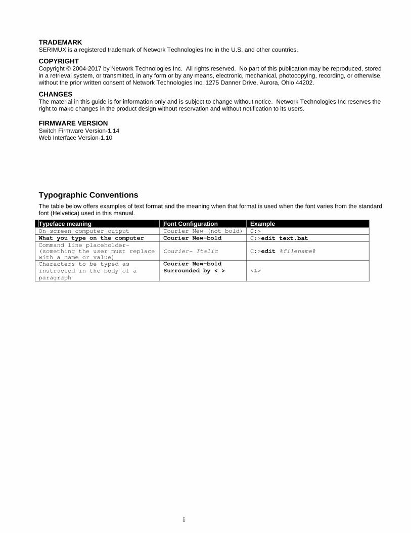
The table below offers examples of text format and the meaning when that format is used when the font varies from the standard font (Helvetica) used in this manual.
Typeface meaning Font Configuration Example On-screen computer output Courier New-(not bold) C:> What you type on the computer Courier New-bold C:>edit text.bat Command line placeholder- (something the user must replace with a name or value)
Courier- Italic C:>edit %filename%
Characters to be typed as instructed in the body of a paragraph
Courier New-bold Surrounded by < > <L>
ii
TABLE OF CONTENTS
Introduction.................................................................................................................................................................... 1
Materials ...................................................................................................................................................................... 1 Serial Interface Specifications ..................................................................................................................................... 2 Supported Web Browsers ........................................................................................................................................... 2 Definitions.................................................................................................................................................................... 2
Default User Name and Passwords............................................................................................................................. 3 Features and Functions................................................................................................................................................ 4 Installation...................................................................................................................................................................... 5
To Mount to a Rack ..................................................................................................................................................... 5 Cable Connections ...................................................................................................................................................... 6 Connect to the Ethernet .............................................................................................................................................. 6 Dual Power Option ...................................................................................................................................................... 7
Initial Startup ................................................................................................................................................................. 8 SERIMUX Quick Start ................................................................................................................................................. 8
Using the SERIMUX Console Switch........................................................................................................................... 9 Serial Control- Administrator....................................................................................................................................... 9
Login as the administrator .........................................................................................................................................10 Port List .....................................................................................................................................................................11 Port Settings ..............................................................................................................................................................12
Port serial settings ..................................................................................................................................................14 Baud rate .............................................................................................................................................................14 Data bit ................................................................................................................................................................14 Stop Bit ................................................................................................................................................................14 Parity....................................................................................................................................................................14 Flow Control.........................................................................................................................................................14 Xon or Xoff Characters ........................................................................................................................................15 DTR line behavior................................................................................................................................................15 Inter-character delay............................................................................................................................................15 Line-break receive or transmit .............................................................................................................................15 Copy Port Serial Settings ....................................................................................................................................16 Display serial settings for different port number .................................................................................................. 16
Modem settings.......................................................................................................................................................16 Port data buffer .......................................................................................................................................................17 Clear Port data buffer .............................................................................................................................................18
User List ....................................................................................................................................................................18 User Settings .............................................................................................................................................................19
Port access .............................................................................................................................................................20 Copy User Settings.................................................................................................................................................20
Advanced Settings.....................................................................................................................................................21 Change administrator password ............................................................................................................................. 21 Firmware .................................................................................................................................................................22
Load new firmware ..............................................................................................................................................22 Save current firmware .........................................................................................................................................22
Network Settings.....................................................................................................................................................23 Reboot .......................................................................................................................................................................24
Serial control-Users ....................................................................................................................................................25 User "Accessible host list" screen .............................................................................................................................25 User main menu ........................................................................................................................................................26 Port List screen..........................................................................................................................................................27 User Terse mode.......................................................................................................................................................28
Terse mode commands ..........................................................................................................................................28 Firmware Upgrade.....................................................................................................................................................30
Keypad Control............................................................................................................................................................32 Functions of the Keypad............................................................................................................................................32
Login the administrator ...........................................................................................................................................32 Disconnect the administrator or a user with administrative privileges.................................................................... 33 Login a user to the administrator main menu ......................................................................................................... 33
iii
Login user to a port .................................................................................................................................................33 Login user to a port and connect the user port to a host port................................................................................. 34 Disconnect and logout a user .................................................................................................................................34 Connect 2 host ports...............................................................................................................................................34 Disconnect 2 ports ..................................................................................................................................................35 Attach or detach a modem......................................................................................................................................35
Reset SERIMUX Console Switch to default settings ................................................................................................ 35 Web Interface...............................................................................................................................................................36
Enter the Password ................................................................................................................................................36 Serial Port Connect ...................................................................................................................................................37 Port Configuration......................................................................................................................................................38
Port List Page .........................................................................................................................................................38 Disconnect Port Page .............................................................................................................................................39 Connect Two Host Ports.........................................................................................................................................39 Clear Port Buffer .....................................................................................................................................................40 Port Settings ........................................................................................................................................................... 40 Serial Settings.........................................................................................................................................................41 Modem Settings......................................................................................................................................................43 Copy Port Settings..................................................................................................................................................44
User Management .....................................................................................................................................................45 User List..................................................................................................................................................................45 Disconnect User......................................................................................................................................................45 User Settings ..........................................................................................................................................................46 Copy User Settings.................................................................................................................................................47
Administrative Settings..............................................................................................................................................48 Admin Config ..........................................................................................................................................................48 Change Admin Password ....................................................................................................................................... 48 Auto Login User ......................................................................................................................................................49 Telnet Base Port .....................................................................................................................................................50 Firmware Update ....................................................................................................................................................51
Network Settings .......................................................................................................................................................52 Enterprise Settings..................................................................................................................................................52 IP Configuration ......................................................................................................................................................52
Support ......................................................................................................................................................................53 Reboot .......................................................................................................................................................................53 Logout........................................................................................................................................................................53
Device Discovery Tool ................................................................................................................................................54 Command Line Interface ............................................................................................................................................55
Helpful Hints ..............................................................................................................................................................57 Update Firmware from CLI ........................................................................................................................................58
RESET Button..............................................................................................................................................................59 Interconnection Cable Wiring Method ...................................................................................................................... 60 Troubleshooting ..........................................................................................................................................................60 Specifications ..............................................................................................................................................................64 Index .............................................................................................................................................................................65 Warranty Information ..................................................................................................................................................65
TABLE OF FIGURES Figure 1- Secure rackmount ears to switch........................................................................................................................................5 Figure 2- Secure switch to a rack ......................................................................................................................................................5 Figure 3- Connect terminals and devices to SERIMUX Console Switch............................................................................................6 Figure 4- Connect the LAN to the SERIMUX .....................................................................................................................................6 Figure 5- Power connections for SERIMUX with Dual Power option .................................................................................................7 Figure 6- Startup- Accessible host list ...............................................................................................................................................8 Figure 7- Administrator main menu..................................................................................................................................................10 Figure 8- The Port list displays the status of all ports ......................................................................................................................11 Figure 9- The Port settings menu ....................................................................................................................................................12 Figure 10- Control Codes for in-band disconnect sequence ............................................................................................................13
iv
Figure 11- Port serial settings menu ................................................................................................................................................14 Figure 12- Modem settings menu ....................................................................................................................................................16 Figure 13- Port data buffer...............................................................................................................................................................17 Figure 14- User List .........................................................................................................................................................................18 Figure 15- User settings menu.........................................................................................................................................................19 Figure 16- Port access list for User 01.............................................................................................................................................20 Figure 17- Administrator's Advanced settings menu........................................................................................................................21 Figure 18- Firmware menu...............................................................................................................................................................22 Figure 19- The SERIMUX is waiting to save its firmware.................................................................................................................23 Figure 20- Network Settings menu ..................................................................................................................................................23 Figure 21- Reboot SERIMUX from console port connection............................................................................................................24 Figure 22- A user with limited host port access ...............................................................................................................................25 Figure 23- User main menu .............................................................................................................................................................26 Figure 24- A limited user accessible Port list ...................................................................................................................................27 Figure 25- User port in Terse mode.................................................................................................................................................28 Figure 26- Firmware upload window................................................................................................................................................30 Figure 27- Type "AT" to auto-detect baud rate ................................................................................................................................30 Figure 28- Last confirmation before firmware update ......................................................................................................................31 Figure 29- File transfer in progress..................................................................................................................................................31 Figure 30- Keypad and LEDs...........................................................................................................................................................32 Figure 31- Web interface Welcome page.......................................................................................................................................36 Figure 32- Web interface Login Prompt ...........................................................................................................................................36 Figure 33- Serial Port Connect Page ...............................................................................................................................................37 Figure 34- Telnet Port connection via Java Applet ..........................................................................................................................37 Figure 35- Serial connection-"offline"-properly exited ......................................................................................................................38 Figure 36- Port List page .................................................................................................................................................................38 Figure 37- Disconnect Port page .....................................................................................................................................................39 Figure 38- Connect Two Host Ports page........................................................................................................................................39 Figure 39- Clear Port Buffers page ..................................................................................................................................................40 Figure 40- Port Settings page ..........................................................................................................................................................40 Figure 41- Change Port Settings page.............................................................................................................................................41 Figure 42- Serial Settings page .......................................................................................................................................................41 Figure 43- Change Serial Settings page ..........................................................................................................................................42 Figure 44- Modem Settings page.....................................................................................................................................................43 Figure 45- Change Modem Settings page .......................................................................................................................................43 Figure 46- Copy Port Settings page.................................................................................................................................................44 Figure 47- User List page ................................................................................................................................................................45 Figure 48- User Disconnect page ....................................................................................................................................................45 Figure 49- Change User Settings page............................................................................................................................................46 Figure 50- Change User Settings page............................................................................................................................................46 Figure 51- Copy User Settings page................................................................................................................................................47 Figure 52- Unit Settings page ..........................................................................................................................................................48 Figure 53- Change Admin Password page ......................................................................................................................................48 Figure 54- Auto Login User page.....................................................................................................................................................49 Figure 55- Telnet Base Port page....................................................................................................................................................50 Figure 56- Firmware Update page ...................................................................................................................................................51 Figure 57- Network Setup-Enterprise Settings page........................................................................................................................52 Figure 58- Network Setup- Network Settings page..........................................................................................................................52 Figure 59- Support page ..................................................................................................................................................................53 Figure 60- Reboot the SERIMUX from the Web Interface ...............................................................................................................53 Figure 61- Device Discovered..........................................................................................................................................................54 Figure 62- Command Line Interface login........................................................................................................................................55 Figure 63- List of CLI commands.....................................................................................................................................................55 Figure 64- Sample txt files for configuring Port 16 ...........................................................................................................................57 Figure 65- Location of RESET button ..............................................................................................................................................59 Figure 66- View looking into RJ45 female........................................................................................................................................60
APPENDICES Appendix A - SERIMUX Port Characteristics...................................................................................................................................61 Appendix B - SERIMUX User and Administrator Characteristics.....................................................................................................61 Appendix C- Cable Adapters ...........................................................................................................................................................62
NTI SERIMUX SERIES CONSOLE SWITCH
1
INTRODUCTION The NTI SERIMUX-CS-x Console Switch is a serial port router that allows links (or connections) between multiple pairs of RS232 asynchronous serial ports. The SERIMUX-CS-x (x=4,8,16,24,or 32) is available with up to 32 serial port connections. The main purpose of the switch is to enable users to manage several serial devices from local or remote locations (using external modems). Devices include routers, DSU's, servers, switches or any other equipment allowing serial operation using RS232 interface. Users can work locally using a VT100 or ANSI serial console or a CPU with a terminal program (i.e. HyperTerminal)) or from remote locations via optional Ethernet connection. Each SERIMUX port has to be configured for serial communication (baud rate, parity, etc) within the specifications of the attached serial device, but the configurations of the two devices linked by the SERIMUX do not need to match. Various parameters (communication speed, hardware and/or software flow control, timeout, etc) can be selected for each SERIMUX port. Devices may be either locally connected or connected through attached modems. Each SERIMUX port can be configured as either a host or user port. Serial hosts (such as servers, switches etc.) are connected to host ports, while serial user devices (such as a terminal or serial console) are connected to user ports. The SERIMUX Console Switch supports two operator levels: user and administrator. Users login at user ports and connect to serial devices attached at host ports. The administrator (logged in at any user port) and users with administrative privileges can see and/or modify various port or user parameters.
Option:
Ethernet Option- includes an Ethernet port for controlling the SERIMUX using a WEB interface or Command Line
Interface via a Local Area Network (LAN)- to order, add an “E” to the part number (i.e. SERIMUX-CS-xE)
Dual Power Option- includes a second power connector for a secondary power supply cable- to order, add a “DP” to
the part number (i.e. SERIMUX-CS-xDP)
Materials Materials Supplied with this kit: SERIMUX Console Switch 4-#10-32 x 3/4" pan head screws and #10-32 cage nuts (server cabinet mounting hardware) Rackmount ears kit Power cord, country specific (2-power cords with Dual Power option only) DB25F-RJ45F Console Adapter RJ45-DB25 Female DB25M-RJ45F-T Console Adapter RJ45-DB25 Male DB25M-RJ45F-C Modem Adapter RJ45- DB25 Male DB9F-RJ45F Serial Adapter RJ45-DB9 Female RJ45MF-RS232-CO Serial Crossover Adapter Materials Required but not supplied: Serial cable with at least one RJ45 male end for connection to the Console Switch from each device to be connected. See Interconnection Cable Wiring Method on page 60 for cable pinout.
NTI SERIMUX SERIES CONSOLE SWITCH
2
Serial Interface Specifications Number of ports: 5, 9, 17, 25 or 33 RS232 ports; Connectors: RJ45 male Data: asynchronous, 5, 6, 7, or 8 bits per character, Parity: even, odd, or none Stop Bits: 1, 1 ½, or 2 bits Flow Control: Xon/Xoff, RTS/CTS, Both, or None Baud Rate: 50 bps to 128,000 bps
Supported Web Browsers Most modern web browsers should be supported. The following browsers have been tested: Microsoft Internet Explorer 6.0 or higher Netscape 7.0 or higher Mozilla FireFox 0.9.2 or higher Opera 9.0 or higher
Set your browser to always check if there is a newer version of the page than the version stored in cache. This action will ensure that it will display the most up-to-date information.
Note: For the Web Interface applet to function in your browser Java must be installed. Most versions of Java 6 or any version of Java 7 will work with it. Do not upgrade to Java 8. The applet will not work with Java 8.
Definitions device equipment that can transmit and/or receive data using RS232 interface inactivity when a port is not receiving data from the device connected to it terminal program a terminal emulation program- computer program that communicates via RS232 interface
(i.e. HyperTerminal) "dumb" terminal Serial terminal device or CPU terminal program that emulates a serial terminal timeout time period of inactivity after which a port will be disconnected (the inter-port connection will be broken) Baud rate serial device or port receiver and transmitter speed; measured in "bps" (bits per second) Flow control a method to temporarily stop and restart serial data transfer (flow). It can be
- Hardware (out-band)- usually using the RTS and CTS physical handshaking signals; - Software (in-band)- using special characters, usually named Xon and Xoff, inserted
in data being transferred; - Both
Disconnect sequence 1 or 3 char sequence inserted in the serial data flow, to disconnect the user from the attached serial device and to return to the initial user menu.
[CR] "Carriage Return" character, ASCII code 13 [LF] "Line Feed" character, ASCII code 10 [FF] "Form Feed" character, ASCII code 09 + (i.e. [ Shift ] + [ < ] ) press the keys simultaneously - (i.e. [ P ] - [ 0 ] ) press the P and 0 keys consecutively
NTI SERIMUX SERIES CONSOLE SWITCH
3
DEFAULT USER NAME AND PASSWORDS
The default Web Interface user name is root (lower case letters only). The default Web Interface password is nti (lower case letters only). For instruction on using the Web Interface, see page 36.
The default Keypad PIN number is 9999 (or 4444 for SERIMUX-CS-4) . For more on Keypad Control, see page 32.
NTI SERIMUX SERIES CONSOLE SWITCH
4
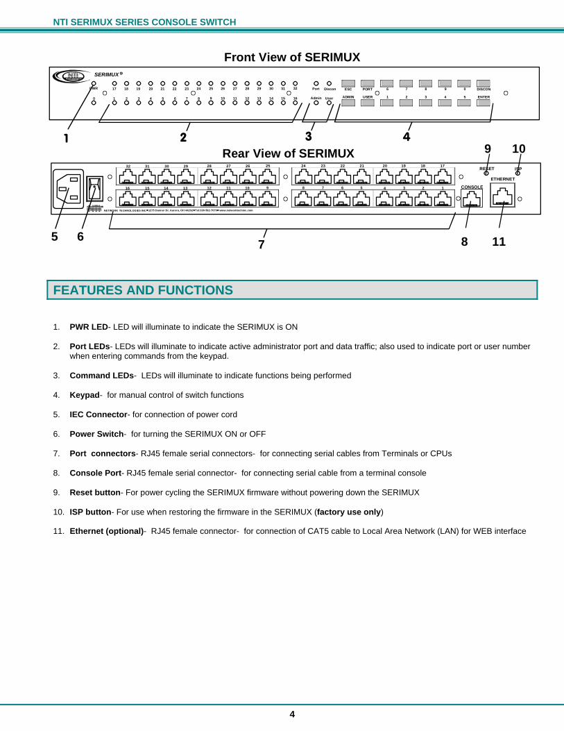
FEATURES AND FUNCTIONS 1. PWR LED- LED will illuminate to indicate the SERIMUX is ON 2. Port LEDs- LEDs will illuminate to indicate active administrator port and data traffic; also used to indicate port or user number
when entering commands from the keypad. 3. Command LEDs- LEDs will illuminate to indicate functions being performed 4. Keypad- for manual control of switch functions 5. IEC Connector- for connection of power cord 6. Power Switch- for turning the SERIMUX ON or OFF 7. Port connectors- RJ45 female serial connectors- for connecting serial cables from Terminals or CPUs 8. Console Port- RJ45 female serial connector- for connecting serial cable from a terminal console 9. Reset button- For power cycling the SERIMUX firmware without powering down the SERIMUX 10. ISP button- For use when restoring the firmware in the SERIMUX (factory use only) 11. Ethernet (optional)- RJ45 female connector- for connection of CAT5 cable to Local Area Network (LAN) for WEB interface
Rear View of SERIMUX
Front View of SERIMUX
2 3 41
5
CONSOLE910111213141516 12345678
2526272829303132 21222324 17181920RESET ISP
ETHERNET
NETWORK TECHNOLOGIES INC Tel:330-562-70701275 Danner Dr, Aurora, OH 44202 www.networktechinc.comNTI R
0 2 3 4 5 6 7 8 91 10 11 12 13 14 15 16
PWR 18 19 20 21 22 23 24 2517 26 27 28 29 30 31 32 ESC
ADMIN USER
PORT 6
1 2 3 4 5 ENTER
DISCON7 8 9 0Discon
UserAdmin
Port
SERIMUX RNTI R
Network T echnologies Inc
76
9 10
118
NTI SERIMUX SERIES CONSOLE SWITCH
5
INSTALLATION This NTI switch was designed to be mounted to a rack or to set on a desktop. It includes rack mount ears to make attachment to a rack easy, and rubber feet to be applied to the bottom of the case if it will instead sit on a flat surface. If this will sit on a flat surface, simply apply the rubber feet to the bottom of the case in each of the 4 corners.
To Mount to a Rack
1. Attach the ears to the switch using the #6-32x3/16" flat Phillips-head screws (6) provided as shown in the illustration below. The holes in the ears should line up with pre-threaded holes in the sides of the NTI switch. Tighten the screws securely.
Figure 1- Secure rackmount ears to switch 2. Install 4 cage nuts (supplied) to the rack in locations that line up with the holes in the mounting ear on the NTI switch. 3. Secure the NTI switch to the rack using four #10-32X3/4” screws (supplied). Each screw should be of sufficient length to go completely through the NTI mounting ear, rack frame and fully engage all threads in the cage nut. Be sure to tighten all mounting screws securely. 4. Attach all cables securely to the switch and where necessary supply adequate means of strain relief for cables.
Figure 2- Secure switch to a rack
Cage Nuts
#10-32X3/4" Screws
Rack
(supplied)
(supplied)
NTI Switch
6-32x3/16" Flat HeadScrews (supplied)
Rackmount Ear
NTI Switch
Front of Switch
NTI SERIMUX SERIES CONSOLE SWITCH
6
Cable Connections
1. Connect a serial device to the port labeled "CONSOLE" on the SERIMUX using a serial cable with an RJ45 male connector (see cable specification on page 60). This will be the default administrator device. (Figure 3)
2. Connect each additional serial device or host to be connected by the SERIMUX to any remaining port (1-8/16/24/32) using a DTE or DCE type serial cable. The SERIMUX is a DCE type device so all ports are pinned-out accordingly. It may be necessary to add one of the cable adapters (supplied) detailed in Appendix C (page 62) between the device port on the serial device or host and the RJ45 connector. An NTI RJ45MF-RS232-CO serial crossover adapter has been provided for connection of one DCE type device. More adapters can be purchased separately.
Note: There are two types of serial devices, data communication equipment (DCE)(i.e. modem) and data terminal equipment (DTE) (i.e. CPU), each having different connector pin assignments. The cable adapters (see Appendix C on page 62) make the proper connections. If your device does not communicate with the SERIMUX when plugged directly in with a pin-to-pin straight thru type connection, try adding a RJ45MF-RS232-CO crossover adapter. If the device does not work with a crossover adapter, try using a cable wired straight through pin-to-pin. 3. Follow the "Initial Startup" instructions on page 8.
Figure 3- Connect terminals and devices to SERIMUX Console Switch
Connect to the Ethernet If the Ethernet option is present, the Web Interface (page 36) will be used. An Ethernet connection to the Local Area Network (LAN) must be made using Cat5 cable with RJ45 connectors attached. Wiring between connectors should be straight through (pin 1 to pin 1, pin 2 to pin 2, etc..) Connect a Cat5 cable between the connector labeled "ETHERNET" and the LAN (see Figure 4).
Figure 4- Connect the LAN to the SERIMUX
USER DEVICE(VT100, ANSI serial console, PC w/ Terminal Emulation Program)
RJ45 Male Connector
ROUTER
FIREWALL
Ethernet cable
PBX
CONSOLE910111213141516 12345678
2526272829303132 21222324 17181920RESET ISP
ETHERNET
NETWORK TECHNOLOGIES INC Tel:330-562-70701275 Danner Dr, Aurora, OH 44202 www.networktechinc.comNTI R
Rear View of SERIMUX
RJ45 maleconnector
LAN
CONSOLE910111213141516 12345678
2526272829303132 21222324 17181920RESET ISP
ETHERNET
NETWORK TECHNOLOGIES INC Tel:330-562-70701275 Danner Dr, Aurora, OH 44202 www.networktechinc.comNTI R
Rear View of SERIMUX
RJ45MF-RS232-COSERIAL CROSSOVER ADAPTER(FOR CONNECTION OF DCETYPE DEVICE TO SERIMUX) (Qty 1- supplied)
NTI SERIMUX SERIES CONSOLE SWITCH
7
Dual Power Option The SERIMUX-CS-xDP has two IEC connectors on the rear, for connection to two separate power sources. If the power source connected to “PWR 1” fails, the ENVIROMUX will automatically and without interruption switch over to the power source connected to “PWR 2” .
Note: If only one power source is used, it should be connected to “PWR 1”.
Note: The power ON/OFF switch is located on the front panel of SERIMUX when two IEC connectors are present.
Figure 5- Power connections for SERIMUX with Dual Power option
CONSOLE910111213141516 12345678
2526272829303132 21222324 17181920RESET ISP
ETHERNET
NETWORK TECHNOLOGIES INC Tel:330-562-70701275 Danner Dr, Aurora, OH 44202 www.networktechinc.com
Rear View of SERIMUXPWR 2PWR 1
250V,2A 250V,2A
UPS 1
UPS 2
PWR 1 PWR 2
Uninterruptible Power Supplies
NTI SERIMUX SERIES CONSOLE SWITCH
8
INITIAL STARTUP
SERIMUX Quick Start The following instruction will enable the user to quickly make port connections using a terminal connected to the “CONSOLE” port. For instruction to make quick connection using the optional Ethernet port and Web Interface, see page 36.
1. Make sure the SERIMUX is turned OFF. 2. Using the serial device connected to the port labeled "CONSOLE", start the terminal program (e.g. Windows HyperTerminal)
and configure it as follows: direct connection (using the appropriate CPU local serial Com port) 9600 bps 8 bits no parity 1 stop bit no flow control ANSI or VT100 terminal mode.
Within the SERIMUX firmware, the "CONSOLE" port is identified as Port 0. For consistency, when Port 0 is mentioned within this manual, it refers to the terminal connected at "CONSOLE".
3. Power ON the SERIMUX. Wait 2 seconds. 4. Press [ Enter ] on the keyboard and wait 3 seconds to be recognized as the default SERIMUX user. The "Accessible host list"
for "User01", logged in at "Port00" will be displayed (see Figure 6). By default, all ports are configured as Host ports and all are accessible.
NOTE: If the user menu does not display reset the SERIMUX following the "Reset SERIMUX Console Switch to default settings" instructions on page 35. 5. To connect to an attached CPU, enter the number of the port the CPU is connected to and press [Enter].
Figure 6- Startup- Accessible host list
NTI SERIMUX SERIES CONSOLE SWITCH
9
USING THE SERIMUX CONSOLE SWITCH The SERIMUX Console Switch is controlled using
Serial Control- from a "dumb" terminal- locally-connected - through an external modem from a remote location
Keypad Control (reduced set of commands) Web Interface- from optional Ethernet connection to a LAN Command Line Interface- from optional Ethernet connection to a LAN
Serial Control The SERIMUX Console Switch can be easily configured using serial communications from either a locally-connected “dumb” terminal or from a terminal remotely connected through a modem. Using a keyboard-controlled menu, the user can modify various parameters and options for each port. The administrator menu can be accessed by the administrator for full feature control, or the user menu, by any user, for more restricted control of port connections. Keypad Control The keypad has direct control over basic SERIMUX functions. The keypad can be used to make changes to port connections regardless of any menu control taking place. Command LEDs on the front panel of the SERIMUX Console Switch indicate the status of the switch and what function is being performed. For more on Keypad Control, see page 32.
Note: The keypad will only work after first entering the assigned PIN number. See page 32 for more info.
The default keypad PIN number is 9999 (or 4444 for SERIMUX-CS-4). Web Interface With an Ethernet connection to a LAN, the user can remotely control SERIMUX port configuration and connections. The administrator menu can be accessed by the administrator for full feature control, or the user menu, by any user, for more restricted control of port connections. For more on Web Interface control, see page 36. Command Line Interface With an Ethernet connection to a LAN, the administrator can additionally remotely view and change the SERIMUX port configuration using HyperTerminal (or other Telnet client). CLI commands can be sent individually or in groups to quickly configure the SERIMUX. For more on CLI commands, see page 55.
SERIAL CONTROL- ADMINISTRATOR Using serial control, the SERIMUX supports 2 operator levels, administrator and user, each with separate password protection for security.
The administrator logs in using an administrator password
administrator name : administrator or root (all lowercase letters) administrator password : nti (all lowercase letters)
Users login using a password set by the administrator
FYI: Users may be granted administrative access rights by the administrator. The administrator and any user with administrative rights can:
view / modify port parameters; view / modify user parameters and user access rights to ports; disconnect ports, logout users etc.
The administrator name cannot be changed. To change the administrator password, see page 21.
NTI SERIMUX SERIES CONSOLE SWITCH
10
Login as the administrator 1. From the user terminal connected to port 0, open the terminal program (configured as described on page 8 under "SERIMUX
Quick Start"). 2. Press [ Enter ] on the keyboard, wait three (3) seconds, and the port will open to the "Accessible host list" for "User01",
logged in at "Port00". 3. Press [Esc] to logout, and [Y] to confirm. A message will be displayed "Disconnecting user now" 4. Press [Spacebar] or [Enter]. A prompt requesting a Username will appear.
5. Enter administrator or root (all lowercase letters) and press [Enter]. A prompt requesting a password will appear.
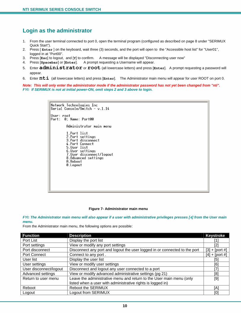
6. Enter nti (all lowercase letters) and press [Enter]. The Administrator main menu will appear for user ROOT on port 0.
Note: This will only enter the administrator mode if the administrator password has not yet been changed from "nti". FYI: If SERIMUX is not at initial power-ON, omit steps 2 and 3 above to login.
Figure 7- Administrator main menu FYI: The Administrator main menu will also appear if a user with administrative privileges presses [4] from the User main menu. From the Administrator main menu, the following options are possible: Function Description Keystroke Port List Display the port list [1] Port settings View or modify any port settings [2] Port disconnect Disconnect any port and logout the user logged in or connected to the port [3] + [port #] Port Connect Connect to any port . [4] + [port #] User list Display the user list [5] User settings View or modify user settings [6] User disconnect/logout Disconnect and logout any user connected to a port [7] Advanced settings View or modify advanced administrative settings (pg 21) [8] Return to user menu Leave the administrative menu and return to the User main menu (only
listed when a user with administrative rights is logged in) [9]
Reboot Reboot the SERIMUX [A] Logout Logout from SERIMUX [0]
NTI SERIMUX SERIES CONSOLE SWITCH
11
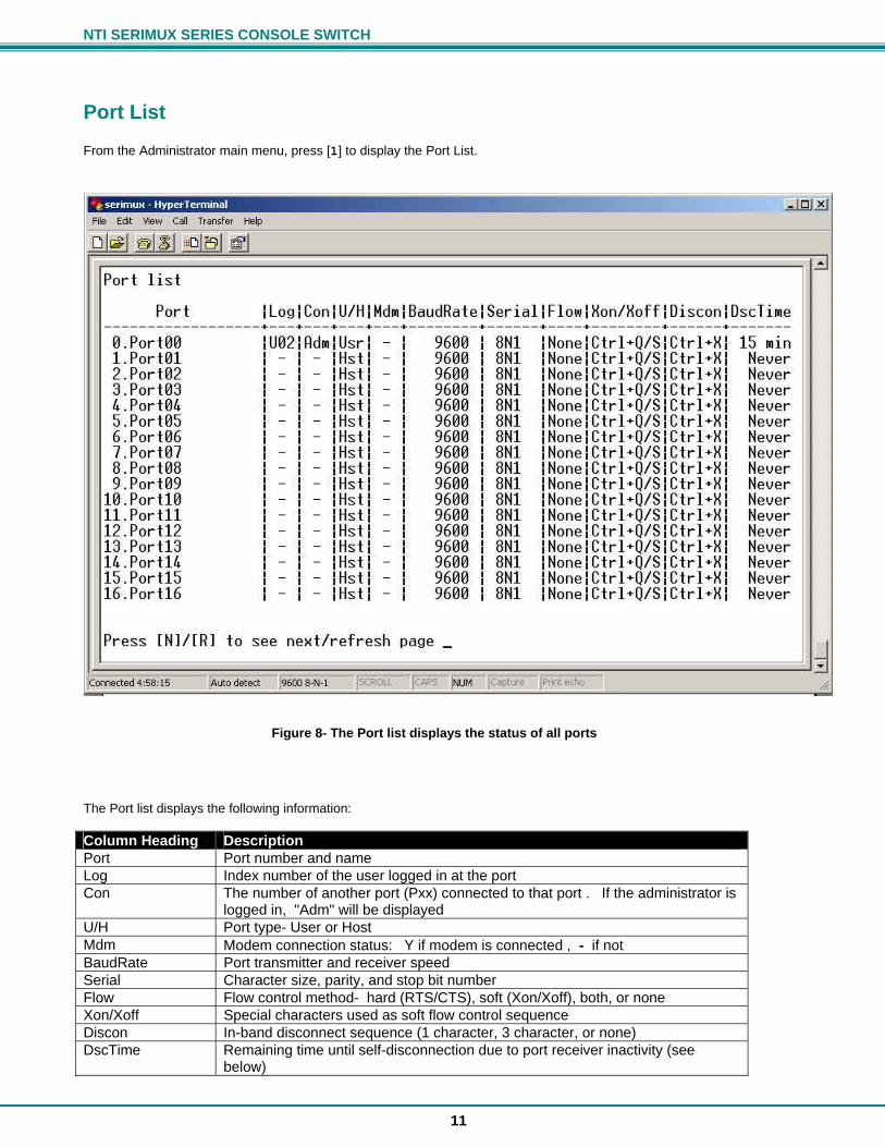
Port List From the Administrator main menu, press [1] to display the Port List.
Figure 8- The Port list displays the status of all ports The Port list displays the following information: Column Heading Description Port Port number and name Log Index number of the user logged in at the port Con The number of another port (Pxx) connected to that port . If the administrator is
logged in, "Adm" will be displayed U/H Port type- User or Host Mdm Modem connection status: Y if modem is connected , - if not BaudRate Port transmitter and receiver speed Serial Character size, parity, and stop bit number Flow Flow control method- hard (RTS/CTS), soft (Xon/Xoff), both, or none Xon/Xoff Special characters used as soft flow control sequence Discon In-band disconnect sequence (1 character, 3 character, or none) DscTime Remaining time until self-disconnection due to port receiver inactivity (see
below)
NTI SERIMUX SERIES CONSOLE SWITCH
12
FYI: RE: DscTime ( Disconnect Time) The value shown in the Port list is derived from various sources depending on the type of connection active at the time.
- If a user is logged into a port as just a user, the time shown will be the remaining time based on the user's timeout setting.
- If a user is logged in with administrative privileges and performing administrative tasks, the time will be based
on the administrator's timeout setting, not based on the user's timeout setting.
- If two ports are connected to each other, and one port has a lower timeout setting than the other, the lower setting will be shown in the DscTime column and control the connection.
- Press [N] to display port information for ports greater than 16, and then [P] to see the previous page. - Press [R] to refresh the information displayed - Press [Esc] or [Spacebar] to return to the Administrator main menu
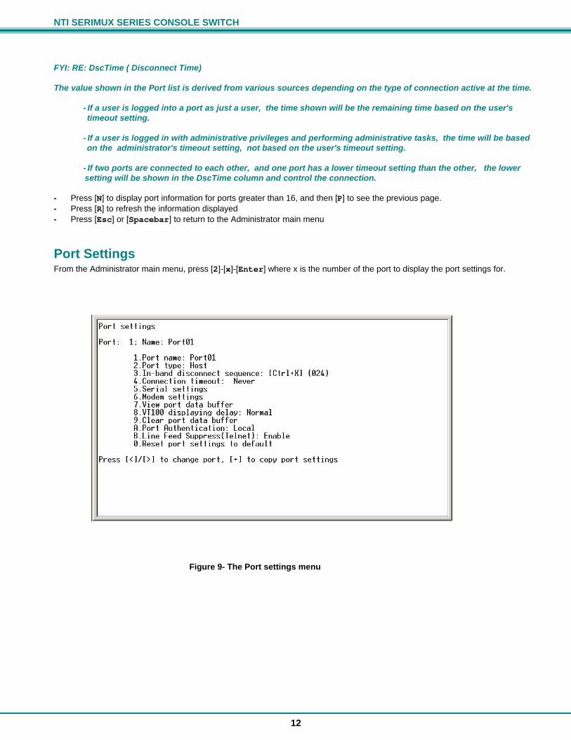
Port Settings From the Administrator main menu, press [2]-[x]-[Enter] where x is the number of the port to display the port settings for.
Figure 9- The Port settings menu
NTI SERIMUX SERIES CONSOLE SWITCH
13
From the Port settings menu, the configuration of each port can be viewed and changed. Setting Description Value Port name Change the port name Max. 15 characters Port type Host or User H or U In-band disconnect sequence
Select characters to use for in-band disconnect sequence
1 + code for 1-character sequence (see table below) 3 + desired characters for 3-character sequence 0- for no disconnect sequence T- display Control code list
Connection Timeout Time left before connection will be broken due to receiver inactivity
0-90 minutes. If 0 is selected, the connection will never timeout.
Serial settings Display serial settings menu N/a Modem settings Display modem settings menu N/a View port data buffer View the last 508 characters received
and transmitted to/from the port N/a
VT100 displaying delay
Modify the displaying extra delay 0 = None,1 = normal, 2 = double, or 3 = triple "None" value can be used if the display is faster (i.e. with a terminal emulator, like HyperTerminal, running on a PC); the other values are useful if real terminals or slower serial devices are used as user/administrator consoles.
Clear port data buffer Clear the data buffer for the selected port
N/a
Port Authentication Define if user authentication is required to access a port via Telnet
Local or None Local = username and password required None= no username or password is required
Line Feed Suppress(Telnet)
Enable or Disable Linefeed Suppression during Telnet session
0 = Disable 1 = Enable (Default)
Reset Port settings to default
Restores factory default port settings A confirmation "Y" will be required
When [3] is pressed to change the in-band disconnect sequence, the choices provided are 0, 1, 3, or T. Pressing a [T] will bring up a Control code list containing key sequences used for 1-character sequences, and the ASCII codes associated with each. (See Fig. 8) To set a 1-character sequence, press [1], then the code from the table associated with the desired sequence. Note: If the 3-character disconnect sequence is enabled, the string: [CR][LF]<3-char sequence>[CR][LF] has to be received to break the connection (7 characters). The [CR] and [LF] ASCII characters stand for 13 and 10 decimal codes (ASCII Carriage Return and Line Feed) respectively. FYI: If the 1-character sequence is selected, the connected device will not receive the disconnect character. If the 3-character sequence is selected, it will be sent to the connected device, prior to breaking the connection.
Figure 10- Control Codes for in-band disconnect sequence - When selecting each new port setting values, press [Esc] or [Spacebar] to cancel, or press [Enter] to save. - Press [>] (greater than symbol) to display the current settings for the next port. - Press [<] (less than symbol) to display the current settings for the previous port - Press [Esc] or [Spacebar] to return to the "Administrator main menu"
NTI SERIMUX SERIES CONSOLE SWITCH
14
Port serial settings From the "Port settings" menu, press [5] to display the "Port serial settings" menu. Using this menu, the administrator can adjust the serial settings of each port, or copy the current port serial settings and paste them to another port or to all ports.
Figure 11- Port serial settings menu
Baud rate
Any baud rate (serial speed) between 50 bps - 128Kbps can be selected, (except for port 0, between 300 bps - 115.2 Kbps). To modify the port serial speed (baud rate);
– press [1], – enter the new value or press [T] for a table listing standard baud rates supported, – and press [Enter]. A confirmation will be required for non-standard baud rate values.
Data bit
The data bit number can be 5, 6, 7, 8, (except for port 0: 7 or 8). To modify the data bit number;
– press [2], – then the bit number: 5, 6, 7, 8
Stop Bit
The stop bit number can be 1, 2, 1.5, (except for port 0: 1 or 2 stop bits). To modify the stop bit number;
– press [3], – then [1] or [2] or [A] to select 1, 2, or 1.5 stop bits respectively.
Note: When Data bit is 5/6 the stop bit can be 1 or 1.5, otherwise it can be 1 or 2
Parity
Parity is set by pressing [4], then [N] for none, [E] for even, or [O] for odd.
Flow Control
The flow control (hand shaking) can be hardware (RTS/CTS or out-band), software (Xon/Xoff or in-band), both or none. To select the flow control;
– press [5], – then [H] or [S] or [B] or [N] respectively.
Note: If "N" for "none" is selected, data may be lost when sending large (greater than 1000 byte) data packets.
NTI SERIMUX SERIES CONSOLE SWITCH
15
Note: If a modem is attached to the port, and hardware and/or software flow control is used, the appropriate command may be added to the modem initialization string:
Flow control Command 1 Command 2 None – – RTS/CTS (hardware) &K3 \Q3 Xon/Xoff (software) &K4 \Q1 Both &K6 disable flow control (not necessary) &K0 \Q0
Consult your modem user manual or the modem AT command manual to find the suitable command.
Xon or Xoff Characters Any non-printable character (ASCII codes between 0 and 31) can be used as flow control Xon or Xoff character. The software flow control is transparent, so the special character is not passed to the connected device. If the Xon and Xoff characters are equal, a toggle mode is automatically used in the software flow control: whenever the special flow control character is received, the current state of flow control is toggled.
To change the Xon or Xoff character; – press [6], – then [0] for Xoff or [1] for Xon, – enter the new value, – then press [Enter] to save it, [Esc] or [Space] to cancel.
FYI: Press [T] after [6] to display a control codes table.
DTR line behavior If a modem is not attached to the serial port, the DTR port line behavior on port disconnection can be selected as follows: the DTR line can be held high (active), low (inactive) or pulsed for 0.5 seconds and then held high. When a modem is attached to the port, the DTR line will be pulsed on port disconnection, disregarding this parameter value. To modify the DTR line behavior on port disconnection;
– press [8], – then [H] or [L] or [P] respectively.
Inter-character delay
An inter-character delay (1 - 60 ms) may be defined, each time a character sequence is transmitted from the port. Using this command, a minimum pause will appear between transmitted characters; for example, certain types of electro-mechanical devices (like teletype equipment) cannot process received characters continuously at their specified baud rate. To select an inter-character delay;
– press [8], – enter the new value (0 for no delay), – and press [Enter] to save it, [Esc] or [Space] to cancel.
FYI: This parameter is not available for port 0.
Line-break receive or transmit
It is possible to accept the line-break received from a port, and to send it from the connected port. The break condition (when received) is defined as zero data with zero parity and no stop bits. To allow or not the line-break receive;
– press [9], – then [Y] for allowed, – [Esc] or [Space] to cancel, any other character to deny.
To define the transmitted line-break extra-duration (this is added to the 1-character transmission time);
– press [0], – then enter the new value (1 - 999 ms) or 0 to disable it, – and press [Enter] to save it, [Esc] or [Space] to cancel.
FYI: These parameters are not available for port 0.
NTI SERIMUX SERIES CONSOLE SWITCH
16
Copy Port Serial Settings
– Press [+] to select the current port as source in a port settings copy-paste process (except port 0). – Then, press [*] to paste the port settings. – Press [Y] to paste the selected port settings to the current port, [A] to paste to all ports, [S] to specify the
destination port, or press any other key to cancel.
Display serial settings for different port number Press [>] (greater than symbol) to display the next higher port serial settings, or press [<] (less than symbol) to display the previous port serial settings. Press [Esc] or [Space] to return to the "Port settings" menu.
Modem settings From the "Port settings" menu, press [6] to display the "Modem settings" menu. Remote connections are possible if modems are used, usually by the users. The remote modem may call in to a local modem attached to a SERIMUX port. A minimum number of port modem settings can be adjusted in the SERIMUX to control the connection (try the default values first; refer to the manual(s) for the modems otherwise).
Figure 12- Modem settings menu The administrator can initialize a modem attached to a SERIMUX port, or disconnect the modem. To control the modem connection from the "Modem settings" menu, the following functions are possible:
Function Keystroke Attach and initialize a modem [1] - [A] Disconnect a modem [1] - [D] Change the modem reset string [2] Change the initialization string [3] Change the hangup string [4] Enable hangup on "NO CARRIER" [5] Save the changes [Enter] Cancel the command [Esc] Reset to default values [0]-[Y]
FYI: If an old modem is attached to a SERIMUX port, it may be necessary to enable the “Hang-up on “NO CARRIER” message” option, in order to hang-up and disconnect the attached modem when receiving this message. Press [5], then [Y] to enable or any other key to disable this option. Usually, this option should remain disabled.

NTI SERIMUX SERIES CONSOLE SWITCH
17
– Press [+] to select the current port as source in a port modem settings copy-paste process (except port 0). – Then, press [*] to paste the port settings. – Press [Y] to paste the selected port settings to the current port, [A] to paste to all ports, [S] to specify the
destination port, or press any other key to cancel. Display modem settings for different port number Press [>] (greater than symbol) to display the next port (next higher port index) modem settings, or press [<] (less than symbol) to display the previous port modem settings. Press [Esc] or [Space] to return to the "Port settings " menu.
Port data buffer From the "Port settings" menu, press [7] to view the port data buffer. In this display the administrator can see the last 508 characters received and transmitted to/from any port. This way the administrator can verify that data was transferred properly between ports.
Figure 13- Port data buffer Press [ P ] to see the previous (older) 128-character page information; press [ N ] to see the next (newer) 128-character page information. Up to 508 received characters and 508 transmitted characters (4 pages) can be inspected, for each port. Press [>] (greater than symbol) or [<] (less than symbol) to change the current port. Press [Esc] or [Space] to return to the "Port settings " menu. FYI: Only the "ROOT" administrator is able to access the port data buffer.
NTI SERIMUX SERIES CONSOLE SWITCH
18
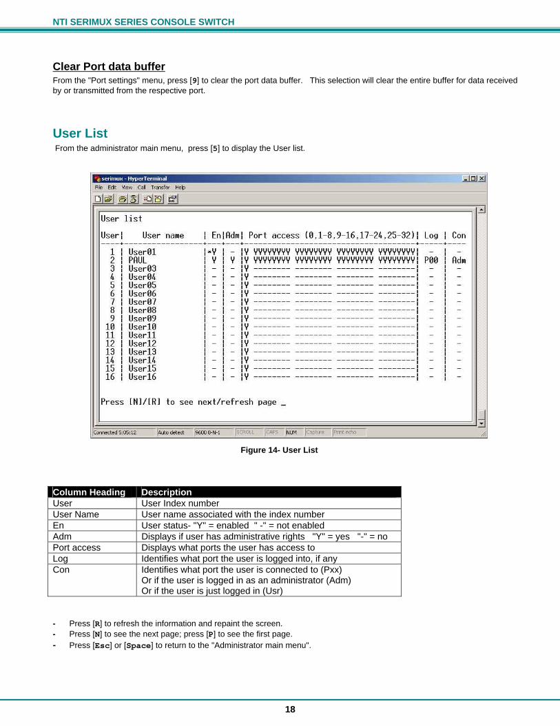
Clear Port data buffer From the "Port settings" menu, press [9] to clear the port data buffer. This selection will clear the entire buffer for data received by or transmitted from the respective port.
User List From the administrator main menu, press [5] to display the User list.
Figure 14- User List Column Heading Description User User Index number User Name User name associated with the index number En User status- "Y" = enabled " -" = not enabled Adm Displays if user has administrative rights "Y" = yes "-" = no Port access Displays what ports the user has access to Log Identifies what port the user is logged into, if any Con Identifies what port the user is connected to (Pxx)
Or if the user is logged in as an administrator (Adm) Or if the user is just logged in (Usr)
- Press [R] to refresh the information and repaint the screen. - Press [N] to see the next page; press [P] to see the first page. - Press [Esc] or [Space] to return to the "Administrator main menu".
NTI SERIMUX SERIES CONSOLE SWITCH
19
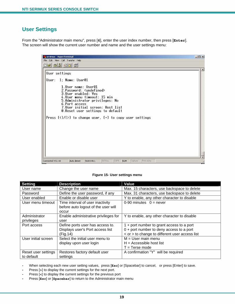
User Settings From the "Administrator main menu", press [6], enter the user index number, then press [Enter]. The screen will show the current user number and name and the user settings menu:
Figure 15- User settings menu Setting Description Value User name Change the user name Max. 15 characters, use backspace to delete Password Define the user password, if any Max. 31 characters, use backspace to delete User enabled Enable or disable user Y to enable, any other character to disable User menu timeout Time interval of user inactivity
before auto logout of the user will occur
0-90 minutes 0 = never
Administrator privileges
Enable administrative privileges for user
Y to enable, any other character to disable
Port access Define ports user has access to. Displays user's Port access list (Fig.14)
1 + port number to grant access to a port 0 + port number to deny access to a port < or > to change to different user access list
User initial screen Select the initial user menu to display upon user login
M = User main menu H = Accessible host list T = Terse mode
Reset user settings to default
Restores factory default user settings
A confirmation "Y" will be required
- When selecting each new user setting values, press [Esc] or [Spacebar] to cancel, or press [Enter] to save. - Press [>] to display the current settings for the next port. - Press [<] to display the current settings for the previous port - Press [Esc] or [Spacebar] to return to the Administrator main menu
NTI SERIMUX SERIES CONSOLE SWITCH
20
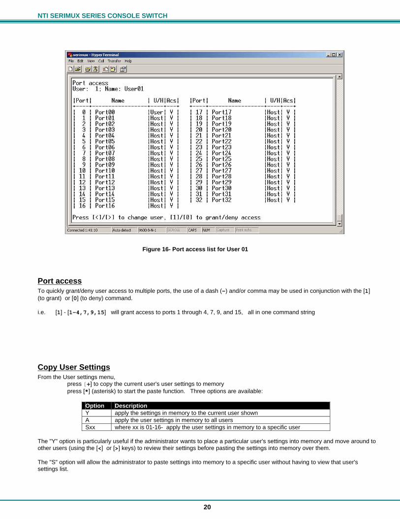
Figure 16- Port access list for User 01
Port access To quickly grant/deny user access to multiple ports, the use of a dash (-) and/or comma may be used in conjunction with the [1] (to grant) or [0] (to deny) command. i.e. [1] - [1-4,7,9,15] will grant access to ports 1 through 4, 7, 9, and 15, all in one command string
Copy User Settings From the User settings menu, press [+] to copy the current user's user settings to memory press [*] (asterisk) to start the paste function. Three options are available:
The "Y" option is particularly useful if the administrator wants to place a particular user's settings into memory and move around to other users (using the [<] or [>] keys) to review their settings before pasting the settings into memory over them. The "S" option will allow the administrator to paste settings into memory to a specific user without having to view that user's settings list.
Option Description Y apply the settings in memory to the current user shown A apply the user settings in memory to all users Sxx where xx is 01-16- apply the user settings in memory to a specific user
NTI SERIMUX SERIES CONSOLE SWITCH
21
Advanced Settings
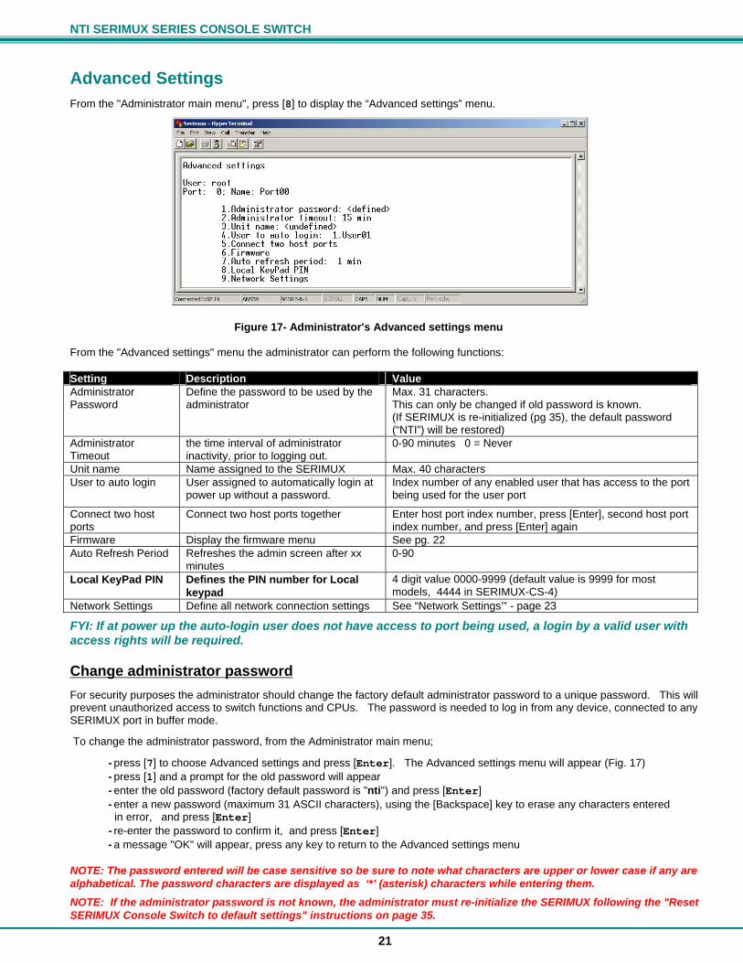
From the "Administrator main menu", press [8] to display the “Advanced settings” menu.
Figure 17- Administrator's Advanced settings menu From the "Advanced settings" menu the administrator can perform the following functions: Setting Description Value Administrator Password
Define the password to be used by the administrator
Max. 31 characters. This can only be changed if old password is known. (If SERIMUX is re-initialized (pg 35), the default password (“NTI”) will be restored)
Administrator Timeout
the time interval of administrator inactivity, prior to logging out.
0-90 minutes 0 = Never
Unit name Name assigned to the SERIMUX Max. 40 characters User to auto login User assigned to automatically login at
power up without a password. Index number of any enabled user that has access to the port being used for the user port
Connect two host ports
Connect two host ports together Enter host port index number, press [Enter], second host port index number, and press [Enter] again
Firmware Display the firmware menu See pg. 22 Auto Refresh Period Refreshes the admin screen after xx
minutes 0-90
Local KeyPad PIN Defines the PIN number for Local keypad
4 digit value 0000-9999 (default value is 9999 for most models, 4444 in SERIMUX-CS-4)
Network Settings Define all network connection settings See “Network Settings’” - page 23
FYI: If at power up the auto-login user does not have access to port being used, a login by a valid user with access rights will be required.
Change administrator password
For security purposes the administrator should change the factory default administrator password to a unique password. This will prevent unauthorized access to switch functions and CPUs. The password is needed to log in from any device, connected to any SERIMUX port in buffer mode.
To change the administrator password, from the Administrator main menu;
- press [7] to choose Advanced settings and press [Enter]. The Advanced settings menu will appear (Fig. 17) - press [1] and a prompt for the old password will appear - enter the old password (factory default password is "nti") and press [Enter] - enter a new password (maximum 31 ASCII characters), using the [Backspace] key to erase any characters entered in error, and press [Enter] - re-enter the password to confirm it, and press [Enter] - a message "OK" will appear, press any key to return to the Advanced settings menu
NOTE: The password entered will be case sensitive so be sure to note what characters are upper or lower case if any are alphabetical. The password characters are displayed as ‘*’ (asterisk) characters while entering them.
NOTE: If the administrator password is not known, the administrator must re-initialize the SERIMUX following the "Reset SERIMUX Console Switch to default settings" instructions on page 35.

NTI SERIMUX SERIES CONSOLE SWITCH
22
Firmware From the Advanced settings menu, press [6] to display the Firmware menu. (From Administrator main menu press [7]-[6])
Figure 18- Firmware menu The Firmware menu has three possible functions: Function Description 1. About Firmware Provides information about SERIMUX including revision number, code length, and CRC 2. Load new firmware Initiate firmware upgrade (see Firmware Upgrade- pg 30) 3. Save current firmware Save present firmware in SERIMUX to binary file
Load new firmware To upgrade the firmware that controls the Console Switch, as soon as improved versions become available, download the firmware file (from the NTI website at www.networktechinc.com) to a local CPU, and follow the instructions under "Firmware Upgrade" on page 30 to install it. Note: Firmware upgrades can only be performed by an administrative user connected to Port 0 or Port 1.
Save current firmware In order to save the firmware currently in SERIMUX, perhaps before installing new firmware, from the Firmware menu: press [3] for Save current firmware. The message shown in Fig.19 will appear.
NTI SERIMUX SERIES CONSOLE SWITCH
23
Figure 19- The SERIMUX is waiting to save its firmware Using the terminal program, configured for Xmodem protocol, transfer the binary file from the SERIMUX to the user’s CPU. (For example, in Windows HyperTerminal, use the Transfer -> Receive File command.) When saving the file, choose a directory to place the file in and a name that will identify it with the extension " .bin" (i.e. SERIMUX1_8.bin). With the file saved, it can be restored from the CPU to the SERIMUX at any time if desired.
Network Settings From the Advanced settings menu, press [9] to display the Network Settings menu. (From Administrator main menu press [7]-[9])
To change a network setting; -press the number associated with the item to change
- use the [Backspace] key to erase any characters to be changed, enter the new characters and press [Enter] - press any key to update the Network Settings menu
Press [Esc] or [Space] to return to the "Advanced Settings menu".
Figure 20- Network Settings menu
NTI SERIMUX SERIES CONSOLE SWITCH
24
Reboot
From the "Administrator main menu", press [A] to initiate a reboot of the SERIMUX. You will be prompted to confirm the command before a reboot will occur. After reboot, you will need to reconnect to the SERIMUX to resume operation.
Figure 21- Reboot SERIMUX from console port connection
NTI SERIMUX SERIES CONSOLE SWITCH
25
SERIAL CONTROL-USERS Users can connect only to accessible ports as defined by the administrator. A list of those ports will be displayed with a successful login. To login, using a serial terminal or an emulator (e.g. Windows HyperTerminal),
1. connect the terminal to the SERIMUX at an allowed user port and press the [Spacebar] or [Enter] key. 2. type a valid user name (assigned by the administrator) and press [Enter]. 3. type a valid password (assigned by the administrator) and press [Enter].
Note: User names and passwords are case sensitive. It is important to know what characters must be capitalized and what characters must not. FYI: The administrator may select a user that will automatically login at power up (User 1 is setup by default). In this case, neither name nor password will be required, just press [Spacebar] or [Enter] after opening the terminal program. After login, the user may connect to an allowed host port, or view host status and parameters. The user is unable to modify port parameters unless the user has been granted administrative privileges.
User "Accessible host list" screen After successful login, the "Accessible host list" will be displayed. The administrator may choose another initial screen to be displayed, following user's preferences. The Accessible host list includes:
user index number and name index number and name of the login port index numbers and names of accessible hosts
Figure 22- A user with limited host port access From the "Accessible host list", the user can perform the following functions: Function Keystroke Connect to host [xx] - [Enter] (where xx is the port index number) Refresh the screen [Spacebar] Logout [Esc] or [Ctrl]+[X] , then [Y] to confirm FYI: The port index numbers are 2-digit decimal numbers. If the wrong number is entered, simply enter the correct number. Only the last two numbers entered before the [Enter] key is pressed will be accepted. The [Enter] key validates the command; [Esc] or [Spacebar] cancels it.
NTI SERIMUX SERIES CONSOLE SWITCH
26
User main menu
The User main menu includes: user index number and name index number and name of the login port user command list
Figure 23- User main menu From the "User main menu" the following functions are possible: Function Keystroke Connect to host port [1]-[xx]-[Enter]
(where xx is the port index number) Display Accessible host list [2]-[Enter] Display accessible host and user ports and info about each
[3]-[Enter]
Login as administrator [4]-[Enter] (only works if user has administrative rights)
Logout [0] then [Y] to confirm Refresh the screen [Spacebar]
A user can only connect to the hosts the user has been allowed access to by the administrator. Press [2] to display a list of accessible hosts.
NTI SERIMUX SERIES CONSOLE SWITCH
27
Port List screen
From the "User main menu", press [3] to display the list of user accessible ports and information about these ports. Only the administrator can change the communication settings.
Figure 24- A limited user accessible Port list
On consecutive columns, the following are displayed: Column Description Port index number of the port Port Name Name assigned to the port Usr/Hst Port type, user or host Modem Yes if modem is attached, - if not BaudRate Receiving and transmitting speed of the port Serial Character size, parity, and stop bit number Flow Defines flow control method
Hard (RTS/CTS or outband) Soft (Xon/Xoff or inband) Both None
Xon/Xoff Characters used for Xon and Xoff flow control Discon In-band disconnect sequence (1-3 characters, or none) Press [R] to refresh and re-display the information on the screen. If the number of user accessible ports is greater than 17, press [N] to see the next page, press [P] to see the first page. Press [Esc] or [Space] to return to the "User main menu".
NTI SERIMUX SERIES CONSOLE SWITCH
28
User Terse mode
This mode is especially useful when the SERIMUX is directly controlled by external software from a serial console (as a user without administrative privileges), rather than being controlled by a user from a keyboard interface.
Entering short command strings performs functions similar to the user main menu commands. A [CR] – [LF] sequence ends every string. The commands are not echoed; the SERIMUX returns to the serial console a specific answer if the command is successfully accomplished or an error message otherwise.
Terse mode can be used only if the administrator configures a user port to enter into Terse mode at login (see page 19). If a keyboard-based user logs into a port intended for Terse mode operation, the following image will appear:
Figure 25- User port in Terse mode
From Terse mode, a limited number of functions are possible;
Terse mode commands Connect to port Send or type in: [C] xx [Enter] where xx is the port index number. The answer will be: OK [CR][LF][LF][FF] If an error occurs (i.e. the port is not accessible), the answer will be: Err [CR][LF]
Accessible host list Send or type in: [H] [Enter] The answer may be, for example: 02,03,04,05,06,07,08,09,10,11,12,13,14,15,16 [CR][LF] (the accessible hosts, separated by commas)
Port info Send or type in: [P] xx [Enter] where xx is the accessible port index number. The answer may be, for example: 04,H, 9600,8N1 ,N,QS,1X [CR][LF] where the comma separated fields stand for:
- port index number; - port type: U or H for User or Host; - port baud rate; - data bits (5..7), parity (N, E, O for None, Even, Odd), stop bits (1, 1.5, 2,); - flow control (N, H, S, B for None, Hard, Soft, Both respectively); - in-band (soft) flow control Xon and Xoff characters (in this example Xon = [Ctrl+Q] and Xoff = [Ctrl+S]); - disconnect sequence length and sequence (i.e. “0 ” for none, “1X ” for 1-char [Ctrl+X] sequence, “3```” for 3-char ``` sequence);
If the port is not accessible to the user, the answer will be: Err [CR][LF]
NTI SERIMUX SERIES CONSOLE SWITCH
29
Verbose mode Send or type in: [V] [Enter] The answer will be: OK [CR][LF] and the Terse mode will be terminated. The “Accessible host list” or the “User main menu” will be displayed. User Logout Send or type in: [L] [Enter] The answer will be: OK [CR][LF] With the next login of the same user, Terse mode will resume.
NTI SERIMUX SERIES CONSOLE SWITCH
30
Firmware Upgrade It may be desired to upgrade the firmware that controls the SERIMUX as soon as improved versions become available. Once the firmware file has been downloaded from www.networktechinc.com to a local CPU, follow these instructions to install it. 1. Log-in as administrator, at ports 0 or 1 (port configured for 9600 bps, 8-bit, no parity, 1 stop bit). Note: During the transfer and the internal upgrade, all ports (except ports 0 and 1) and all users are disconnected. 2. Locate on the local hard disk the binary file containing a valid firmware version (downloaded from the NTI website at
www.networktechinc.com). 3. From the "Firmware" menu (pg 22) press [2], then [Y] to confirm. All other ports will be disconnected and disabled during the
firmware update procedure. Note: When using Port 0 for firmware file transfer, if a different baud rate is desired for file transfer, change it in the terminal program now, before step 4. (Leave the baud rate at 9600 if Port 1 is used for the file transfer.) Remember, to re-establish communication with the SERIMUX after file transfer is complete, the terminal program baud rate must be reset to 9600. .
Figure 26- Firmware upload window 4. Type [A] + [T] “AT” (case sensitve, must be uppercase) to activate the SERIMUX auto baud detection. 5. When prompted, press [Y] to confirm, and [C] to continue with the procedure. Note: Proceeding past this point will erase all programming. The firmware upgrade must be completed for the SERIMUX to function.
Figure 27- Type "AT" to auto-detect baud rate
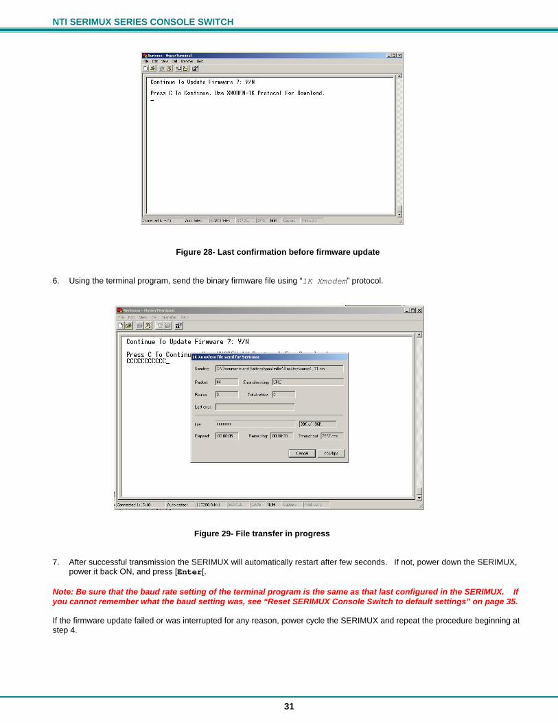
NTI SERIMUX SERIES CONSOLE SWITCH
31
Figure 28- Last confirmation before firmware update 6. Using the terminal program, send the binary firmware file using “1K Xmodem” protocol.
Figure 29- File transfer in progress 7. After successful transmission the SERIMUX will automatically restart after few seconds. If not, power down the SERIMUX,
power it back ON, and press [Enter[. Note: Be sure that the baud rate setting of the terminal program is the same as that last configured in the SERIMUX. If you cannot remember what the baud setting was, see “Reset SERIMUX Console Switch to default settings” on page 35. If the firmware update failed or was interrupted for any reason, power cycle the SERIMUX and repeat the procedure beginning at step 4.
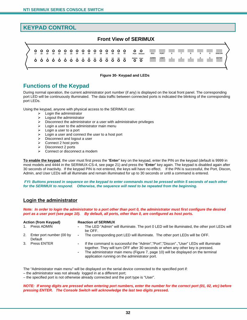
NTI SERIMUX SERIES CONSOLE SWITCH
32
KEYPAD CONTROL
Figure 30- Keypad and LEDs
Functions of the Keypad During normal operation, the current administrator port number (if any) is displayed on the local front panel. The corresponding port LED will be continuously illuminated. The data traffic between connected ports is indicated the blinking of the corresponding port LEDs. Using the keypad, anyone with physical access to the SERIMUX can:
Login the administrator Logout the administrator Disconnect the administrator or a user with administrative privileges Login a user to the administrator main menu Login a user to a port Login a user and connect the user to a host port Disconnect and logout a user Connect 2 host ports Disconnect 2 ports Connect or disconnect a modem
To enable the keypad, the user must first press the “Enter” key on the keypad, enter the PIN on the keypad (default is 9999 in most models and 4444 in the SERIMUX-CS-4, see page 21) and press the “Enter” key again. The keypad is disabled again after 30 seconds of inactivity. If the keypad PIN is not entered, the keys will have no effect. If the PIN is successful, the Port, Discon, Admin, and User LEDs will all illuminate and remain illuminated for up to 30 seconds or until a command is entered. FYI: Buttons pressed in sequence on the keypad to enter commands must be pressed within 5 seconds of each other for the SERIMUX to respond. Otherwise, the sequence will need to be repeated from the beginning.
Login the administrator
Note: In order to login the administrator to a port other than port 0, the administrator must first configure the desired port as a user port (see page 10). By default, all ports, other than 0, are configured as host ports. Action (from Keypad) Reaction of SERIMUX 1. Press ADMIN - The LED “Admin” will illuminate. The port 0 LED will be illuminated, the other port LEDs will
be OFF. 2. Enter port number (00 by
Default - The corresponding port LED will illuminate. The other port LEDs will be OFF.
3. Press ENTER - If the command is successful the “Admin”,”Port”,”Discon”.,”User” LEDs will illuminate together. They will turn OFF after 30 seconds or when any other key is pressed.
- The administrator main menu (Figure 7, page 10) will be displayed on the terminal application running on the administrator port.
The “Administrator main menu” will be displayed on the serial device connected to the specified port if: – the administrator was not already logged in at a different port; – the specified port is not otherwise already connected and the port type is “User”. NOTE: If wrong digits are pressed when entering port numbers, enter the number for the correct port (01, 02, etc) before pressing ENTER. The Console Switch will acknowledge the last two digits pressed.
ESC
ADMIN USER
PORT 6
1 2 3 4 5 ENTER
DISCON7 8 9 0
Front View of SERIMUX
2 3 4 5 6 7 8 91 10 11 12 13 14 15 16
18 19 20 21 22 23 24 2517 26 27 28 29 30 31 32 Discon
UserAdmin
Port
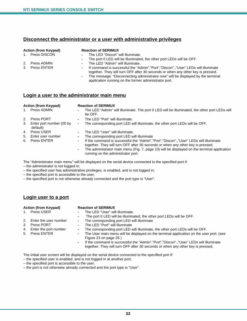
NTI SERIMUX SERIES CONSOLE SWITCH
33
Disconnect the administrator or a user with administrative privileges Action (from Keypad) Reaction of SERIMUX 1. Press DISCON - The LED “Discon” will illuminate.
- The port 0 LED will be illuminated, the other port LEDs will be OFF. 2. Press ADMIN - The LED "Admin" will illuminate. 3. Press ENTER - If command is successful the “Admin”,”Port”,”Discon”.,”User” LEDs will illuminate
together. They will turn OFF after 30 seconds or when any other key is pressed. - The message: “Disconnecting administrator now” will be displayed by the terminal
application running on the former administrator port.
Login a user to the administrator main menu Action (from Keypad) Reaction of SERIMUX 1. Press ADMIN - The LED “Admin” will illuminate. The port 0 LED will be illuminated, the other port LEDs will
be OFF. 2. Press PORT - The LED “Port” will illuminate. 3. Enter port number (00 by default)
- The corresponding port LED will illuminate, the other port LEDs will be OFF.
4. Press USER - The LED “User” will illuminate. 5. Enter user number - The corresponding port LED will illuminate 6. Press ENTER - If the command is successful the “Admin”,”Port”,”Discon”.,”User” LEDs will illuminate
together. They will turn OFF after 30 seconds or when any other key is pressed. - The administrator main menu (Fig. 7, page 10) will be displayed on the terminal application
running on the administrator port. The “Administrator main menu” will be displayed on the serial device connected to the specified port if: – the administrator is not logged in; – the specified user has administrative privileges, is enabled, and is not logged in; – the specified port is accessible to the user; – the specified port is not otherwise already connected and the port type is “User”.
Login user to a port Action (from Keypad) Reaction of SERIMUX 1. Press USER - The LED “User” will illuminate.
- The port 0 LED will be illuminated, the other port LEDs will be OFF. 2. Enter the user number - The corresponding port LED will illuminate 3. Press PORT - The LED "Port" will illuminate 4. Enter the port number - The corresponding port LED will illuminate, the other port LEDs will be OFF. 5. Press ENTER - The User main menu will be displayed on the terminal application on the user port: (see
Figure 23 on page 26 ) - If the command is successful the “Admin”,”Port”,”Discon”.,”User” LEDs will illuminate
together. They will turn OFF after 30 seconds or when any other key is pressed. The initial user screen will be displayed on the serial device connected to the specified port if: – the specified user is enabled, and is not logged in at another port; – the specified port is accessible to the user; – the port is not otherwise already connected and the port type is “User”.
NTI SERIMUX SERIES CONSOLE SWITCH
34
Login user to a port and connect the user port to a host port Action (from Keypad) Reaction of SERIMUX 1. Press USER - The LED “User” will illuminate.
- The port 0 LED will be illuminated, the other port LEDs will be OFF. 2. Enter the user number - The corresponding port LED will illuminate 3. Press PORT - The LED "Port" will illuminate 4. Enter the user port
number - The corresponding port LED will illuminate. The other port LEDs will be OFF.
5. Press PORT again - The LED "Port" will illuminate 6. Enter the host port
number - The corresponding port LED will illuminate. The other port LEDs will be OFF.
7. Press ENTER - The User main menu will be displayed on the terminal application on the user port: (see Figure 23 on page 26 )
- If command is successful the “Admin”,”Port”,”Discon”.,”User” LEDs will illuminate together. They will turn OFF after 30 seconds or when any other key is pressed.
The user will be connected if: – the specified user is enabled, and is not logged in; – the specified ports are accessible to the user; – the user port is not otherwise already connected and the port type is “User”. – the host port is not otherwise already connected and the port type is “Host”.
Disconnect and logout a user Action (from Keypad) Reaction of SERIMUX 1. Press DISCON - The LED “Discon” will illuminate. 2. Press USER - The LED “User” will illuminate. 3. Enter the user number - The corresponding port LED will illuminate, the other port LEDs will be OFF 4. Press ENTER - The LEDs “Port", “Admin”, "User", and "Discon" will illuminate briefly.
Connect 2 host ports Action (from Keypad) Reaction of SERIMUX 1. Press PORT - The LED “Port” will illuminate.
- The port 0 LED will be illuminated. The other port LEDs will be OFF. 2. Enter the first port number - The corresponding port LED will illuminate, the other port LEDs will be OFF 3. Press PORT again - The LED “Port” will illuminate. The port 0 LED will be illuminated, the other port LEDs will be
OFF. 4. Enter the second port
number (to connect the first port number to)
- The corresponding port LED will illuminate. The other port LEDs will be OFF.
5. Press ENTER - If command is successful the “Admin”,”Port”,”Discon”.,”User” LEDs will illuminate together. They will turn OFF after 30 seconds or when any other key is pressed.
The two host ports will be connected if: – the ports are not connected – the ports type is “Host”.
NTI SERIMUX SERIES CONSOLE SWITCH
35
Disconnect 2 ports Action (from Keypad) Reaction of SERIMUX 1. Press DISCON - The LED “Discon” will illuminate.
- The port 0 LED will be illuminated, the other port LEDs will be OFF. 2. Press PORT - 3. Enter the port number - The corresponding port LED will illuminate, the other port LEDs will be OFF. 4. Press ENTER - If command is successful the “Admin”,”Port”,”Discon”.,”User” LEDs will illuminate
together. They will turn OFF after 30 seconds or when any other key is pressed. The administrator can view any changes in port connections made from the keypad by opening the terminal program on any terminal connected to a user port and view the “Port list” (see page 8).
Attach or detach a modem To attach a modem Action (from Keypad) Reaction of SERIMUX 1. Press DISCON - The LED “Discon” will illuminate.
- The port 0 LED will be illuminated, the other port LEDs will be OFF. 2. Press DISCON again - The LED “Discon” will illuminate.
- The port 0 LED will be illuminated, the other port LEDs will be OFF. 3. Press 1 - 4. Press PORT - 5. Enter the port number - The corresponding port LED will illuminate. The other port LEDs will be OFF. 6. Press ENTER - If command is successful the “Admin”,”Port”,”Discon”.,”User” LEDs will illuminate
together. They will turn OFF after 30 seconds or when any other key is pressed. The modem will be initialized and connected if a modem is connected to the specified port and powered ON. The administrator can verify this by viewing the Port list (see page 8). To detach a modem Action (from Keypad) Reaction of SERIMUX 1. Press DISCON - The LED “Discon” will illuminate.
- The port 0 LED will be illuminated, the other port LEDs will be OFF. 2. Press DISCON again - The LED “Discon” will illuminate.
- The port 0 LED will be illuminated, the other port LEDs will be OFF. 3. Press 0 - 4. Press PORT - 5. Enter the port number - The corresponding port LED will illuminate. The other port LEDs will be OFF. 6. Press ENTER - If command is successful the “Admin”,”Port”,”Discon”.,”User” LEDs will illuminate
together. They will turn OFF after 30 seconds or when any other key is pressed.
Reset SERIMUX Console Switch to default settings SERIMUX can be reset to default settings by using the Keypad. This procedure is only necessary if the administrator is unable to access the administrator main menu. This should only occur if an administrator password has been set and the password is not known. The SERIMUX should be OFF before beginning this procedure. 1. Press and hold both local keypad “ADMIN” and “ESC” buttons. 2. Turn ON the SERIMUX. 3. Wait 3 seconds. 4. Release the buttons.
Caution: During the reset, the customer modified parameter values will be replaced with the factory default values (for default values, see page 31, Appendix A); user names and passwords will return to default values (pg. 9).
NTI SERIMUX SERIES CONSOLE SWITCH
36
WEB INTERFACE A user may control the connections of the SERIMUX using a Web Interface via any web browser (see page 2 for web supported browsers) provided the Ethernet option is present and connected. With the SERIMUX connected to a LAN through an Ethernet cable, a user can access the web interface controls inside the SERIMUX.
Note: For the Web Interface applet to function in your browser Java must be installed. Most versions of Java 6 or any version of Java 7 will work with it. Do not upgrade to Java 8. The applet will not work with Java 8.
FYI: To quickly locate a SERIMUX on the LAN and edit the IP address settings, use the Device Discovery Tool (page 54). To access the web interface, type the current IP address into the address bar of the web browser. Address To open a SSL-encrypted connection, type: Address You will be prompted to accept a certificate. Accept the NTI certificate. A "Welcome Page" will appear.
Figure 31- Web interface Welcome page
Enter the Password Select a link to the left to be prompted for a username and password. To change the password, see page 48.
User Name = administrator or root (lower case letters only) Password = nti (lower case letters only)
Note: The browser must be configured to accept cookies in order for the user to successfully make use of the web interface.
Figure 32- Web interface Login Prompt As described on the following pages, each link will enable different areas of control for the SERIMUX.
http://192.168.1.90
https://192.168.1.90
NTI SERIMUX SERIES CONSOLE SWITCH
37
Serial Port Connect
Figure 33- Serial Port Connect Page Select “SERIAL PORT CONNECT” from the side menu. The Serial Port Connect page allows a user to connect to a serial port on the SERIMUX. (In Fig.32, the list shows that User 1 has a Telnet connection to Port 2.) To make a connection with a port, select a Port number. A connection can be made provided:
the port is a host port the port has a serial device connected that is not currently in use the user has access to the port (see page 46)
With these conditions satisfied, a Telnet connection will be initiated. The user will be prompted to login with a SERIMUX user name and password to complete the connection.
Note: The user must click inside the Telnet window before typing any characters.
Figure 34- Telnet Port connection via Java Applet If the port is already in use, the message “Serial port is already in use......try later” will appear in a Telnet window. If the port is configured as a user port and not a host port (see Port Settings- page 40) after logging in to the port the message “Serial port Not in host mode” will appear.
NTI SERIMUX SERIES CONSOLE SWITCH
38
With the user name and password entered, the message “Hello Userxx” will appear and the user will be directly communicating with the serial device. A “Send Break” button is provided in the Telnet window to enable the user to send a break signal to the serial device as needed. To properly exit a completed Telnet connection, type <Ctrl>-<x> to first close the serial connection. The green “onliine” in the upper right corner of the window will change to a red “offline” (see Figure 35). Then press “Close” at the bottom of the Telnet page (see Figure 34) to exit Telnet.
Note: If the user does not properly close a serial connection before exiting Telnet, the user may not be able to reconnect to that serial device later without assistance from the administrator.
Figure 35- Serial connection-"offline"-properly exited If the user did not log in. completing the serial connection to the serial device, then to exit Telnet just press “Close”.
Port Configuration
Port List Page
Figure 36- Port List page Under “PORT CONFIGURATION”, select “Port List” to display the Port List page. The Port List page displays the current configuration and status of each of the SERIMUX ports.
NTI SERIMUX SERIES CONSOLE SWITCH
39
Disconnect Port Page
Figure 37- Disconnect Port page Under “PORT CONFIGURATION”, select “Disconnect Port”. From this screen the administrator can disconnect any port connection desired. Place a check mark in the check box to the right of any connected port and press “Disconnect” at the bottom of the page. The associated port will be immediately disconnected and available for reconnection as needed.
Connect Two Host Ports
Figure 38- Connect Two Host Ports page Under “PORT CONFIGURATION”, select “Connect Two Host Ports” . From this screen the administrator can select any two ports to be connected to each other. Place a check mark in check box to the right of any two ports and press “Connect” at the bottom of the page. The associated ports will be immediately connected.
NTI SERIMUX SERIES CONSOLE SWITCH
40
Clear Port Buffer
Figure 39- Clear Port Buffers page Under “PORT CONFIGURATION”, select “Clear Port Buffer”. From this screen the administrator can clear the entire data buffer for data received by or transmitted from the respective port. Place a check mark in the check box to the right of any port and press “Clear” at the bottom of the page. The data buffer for the respective port will be cleared of all data.
Port Settings
Figure 40- Port Settings page Under “PORT CONFIGURATION”, select “Port Settings” to display the Port Settings page. This page displays the number, name, and connection status of each port. As long as the connection status for a port is “No” (not connected), the settings can be changed. To proceed to the “Change Port Settings” page for any non-connected port, select the desired Port Name. The Change Port Settings page for the respective port will open.
NTI SERIMUX SERIES CONSOLE SWITCH
41
Figure 41- Change Port Settings page The Change Port Settings page provides boxes that can be edited with the settings associated with each port. The settings that can be changed include: Setting Description Acceptable Value Port Name Define the name of the port Max. 15 characters Port Type Define whether the port is a Host port or User port Host or User (default is Host) Disconnect Sequence
Select number of characters to use for in-band disconnect sequence
0 (disabled), 1, or 3 (the default is 1)
Select Disconnect Character
Character to use for in-band Disconnect sequence Any ASCII nonprintable character ; 0-31 range (see drop-down list) (the default is Ctrl-X)
Disconnect Character
User defined characters to use when Disconnect sequence (above) is configured to be 3 characters
Any 3 ASCII characters
Connection Timeout
Time left before connection will be broken due to receiver inactivity
0-90 (minutes) If 0 is selected, the connection will never timeout.
Port Authentication Type
Define if a user will requires authentication to access a port via Telnet
Local or None Local = username and password required None= no username or password is required
Linefeed Suppress Enable or Disable Linefeed Suppression during Telnet session
Enable or Disable Default value is Enable
Once the desired changes have been made, press the “Apply” button to save the settings. The changes will take effect immediately.
Serial Settings
Figure 42- Serial Settings page
NTI SERIMUX SERIES CONSOLE SWITCH
42
Under “PORT CONFIGURATION”, select “Serial Settings”. This page displays the number, name, and connection status of each port. As long as the connection status for a port is “No” (not connected), the serial settings can be changed. To proceed to the “Change Serial Settings” page for any non-connected port, select the desired Port Name. The Change Serial Settings page for the respective port will open.
Figure 43- Change Serial Settings page The Change Serial Settings page provides boxes that can be edited with the serial communication characteristics associated with each port. The characteristics that can be changed include: Setting Value Baud Rate 50bps-128Kbps (except port 0, between 300bps-115.2Kbps) Data Bits 5, 6, 7, or 8 (except port 0, 7 or 8) Stop bits 1, 2, or 1.5 (except port 0, 1 or 2 stop bits) Parity N (none), E (even), O (odd) Flow Control Hardware, Software, Both, or None Xon Character ASCII codes between 0 and 31 (see Fig. 9, pg. 13) Xoff Character ASCII codes between 0 and 31 (see Fig. 9, pg. 13) DTR Line Behavior High, Low, or Pulsed Inter Character Delay 1-60 ms Break Receive Allowed Yes or No Break Transmission Duration 1-999 ms or 0 to disable it Once the desired changes have been made, press the “Apply” button to save the values. The changes will take effect immediately.
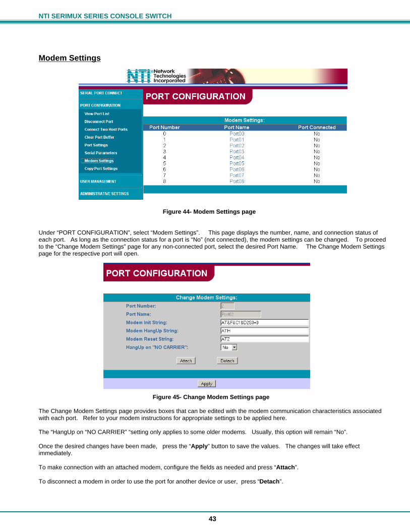
NTI SERIMUX SERIES CONSOLE SWITCH
43
Modem Settings
Figure 44- Modem Settings page Under “PORT CONFIGURATION”, select “Modem Settings”. This page displays the number, name, and connection status of each port. As long as the connection status for a port is “No” (not connected), the modem settings can be changed. To proceed to the “Change Modem Settings” page for any non-connected port, select the desired Port Name. The Change Modem Settings page for the respective port will open.
Figure 45- Change Modem Settings page The Change Modem Settings page provides boxes that can be edited with the modem communication characteristics associated with each port. Refer to your modem instructions for appropriate settings to be applied here. The “HangUp on “NO CARRIER” “setting only applies to some older modems. Usually, this option will remain “No”. Once the desired changes have been made, press the “Apply” button to save the values. The changes will take effect immediately. To make connection with an attached modem, configure the fields as needed and press “Attach”. To disconnect a modem in order to use the port for another device or user, press “Detach”.
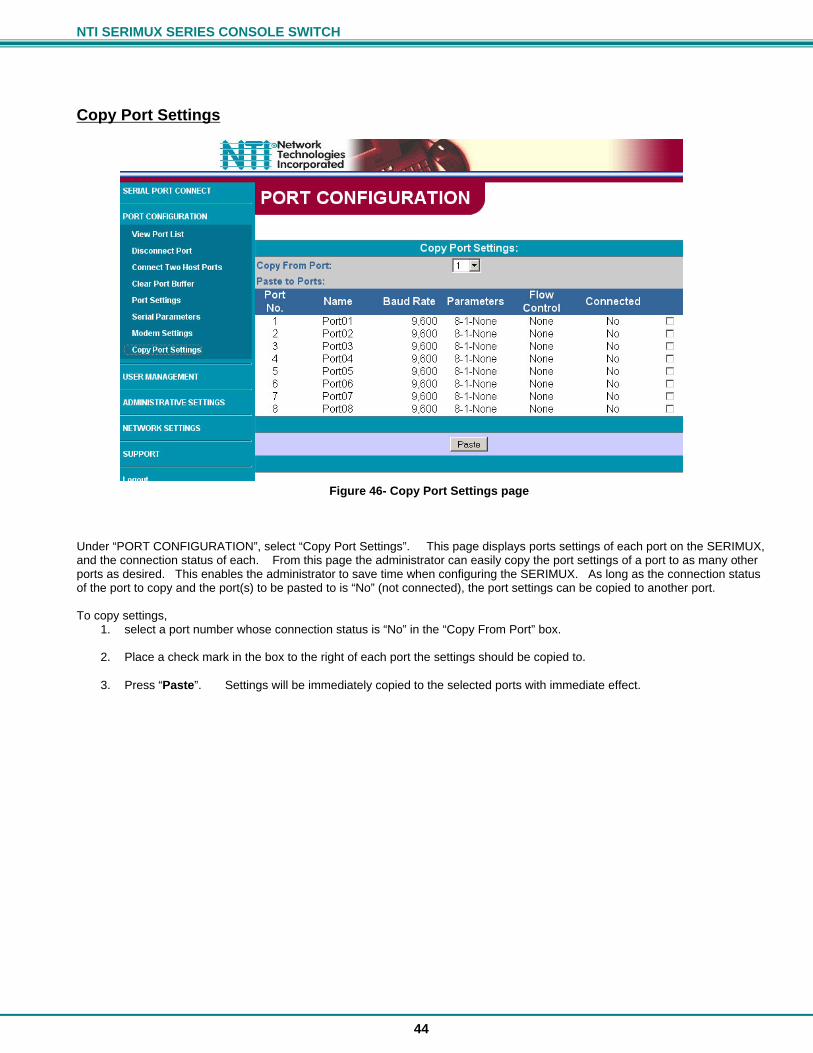
NTI SERIMUX SERIES CONSOLE SWITCH
44
Copy Port Settings
Figure 46- Copy Port Settings page Under “PORT CONFIGURATION”, select “Copy Port Settings”. This page displays ports settings of each port on the SERIMUX, and the connection status of each. From this page the administrator can easily copy the port settings of a port to as many other ports as desired. This enables the administrator to save time when configuring the SERIMUX. As long as the connection status of the port to copy and the port(s) to be pasted to is “No” (not connected), the port settings can be copied to another port. To copy settings,
1. select a port number whose connection status is “No” in the “Copy From Port” box.
2. Place a check mark in the box to the right of each port the settings should be copied to.
3. Press “Paste”. Settings will be immediately copied to the selected ports with immediate effect.
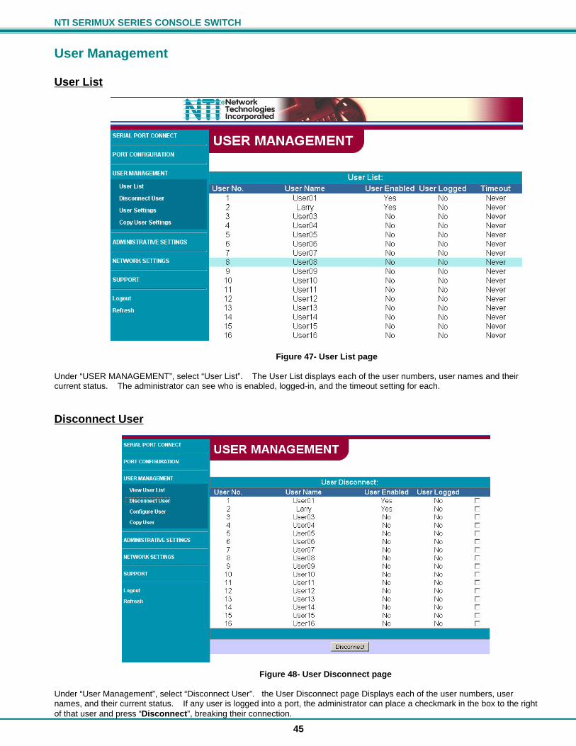
NTI SERIMUX SERIES CONSOLE SWITCH
45
User Management
User List
Figure 47- User List page Under “USER MANAGEMENT”, select “User List”. The User List displays each of the user numbers, user names and their current status. The administrator can see who is enabled, logged-in, and the timeout setting for each.
Disconnect User
Figure 48- User Disconnect page Under “User Management”, select “Disconnect User”. the User Disconnect page Displays each of the user numbers, user names, and their current status. If any user is logged into a port, the administrator can place a checkmark in the box to the right of that user and press “Disconnect”, breaking their connection.
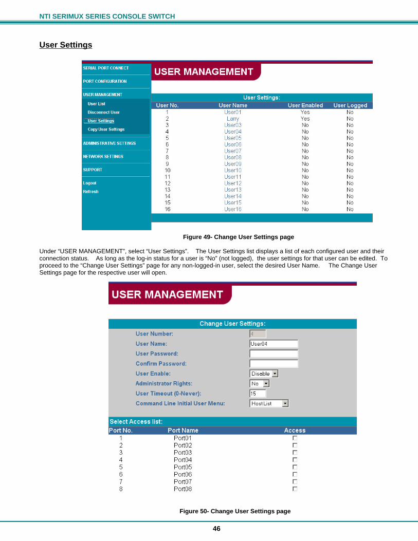
NTI SERIMUX SERIES CONSOLE SWITCH
46
User Settings
Figure 49- Change User Settings page Under “USER MANAGEMENT”, select “User Settings”. The User Settings list displays a list of each configured user and their connection status. As long as the log-in status for a user is “No” (not logged), the user settings for that user can be edited. To proceed to the “Change User Settings” page for any non-logged-in user, select the desired User Name. The Change User Settings page for the respective user will open.
Figure 50- Change User Settings page
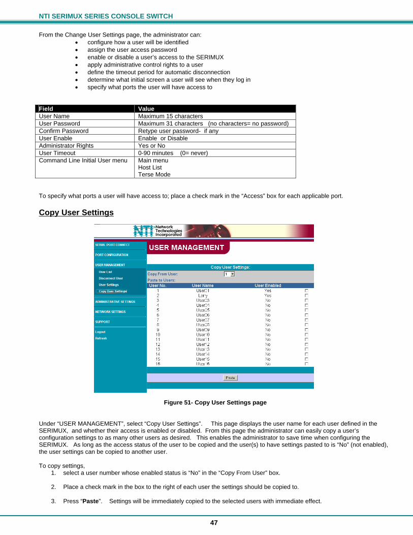
NTI SERIMUX SERIES CONSOLE SWITCH
47
From the Change User Settings page, the administrator can:
configure how a user will be identified assign the user access password enable or disable a user’s access to the SERIMUX apply administrative control rights to a user define the timeout period for automatic disconnection determine what initial screen a user will see when they log in specify what ports the user will have access to
Field Value User Name Maximum 15 characters User Password Maximum 31 characters (no characters= no password) Confirm Password Retype user password- if any User Enable Enable or Disable Administrator Rights Yes or No User Timeout 0-90 minutes (0= never) Command Line Initial User menu Main menu
Host List Terse Mode
To specify what ports a user will have access to; place a check mark in the “Access” box for each applicable port.
Copy User Settings
Figure 51- Copy User Settings page Under “USER MANAGEMENT”, select “Copy User Settings”. This page displays the user name for each user defined in the SERIMUX, and whether their access is enabled or disabled. From this page the administrator can easily copy a user’s configuration settings to as many other users as desired. This enables the administrator to save time when configuring the SERIMUX. As long as the access status of the user to be copied and the user(s) to have settings pasted to is “No” (not enabled), the user settings can be copied to another user. To copy settings,
1. select a user number whose enabled status is “No” in the “Copy From User” box.
2. Place a check mark in the box to the right of each user the settings should be copied to.
3. Press “Paste”. Settings will be immediately copied to the selected users with immediate effect.
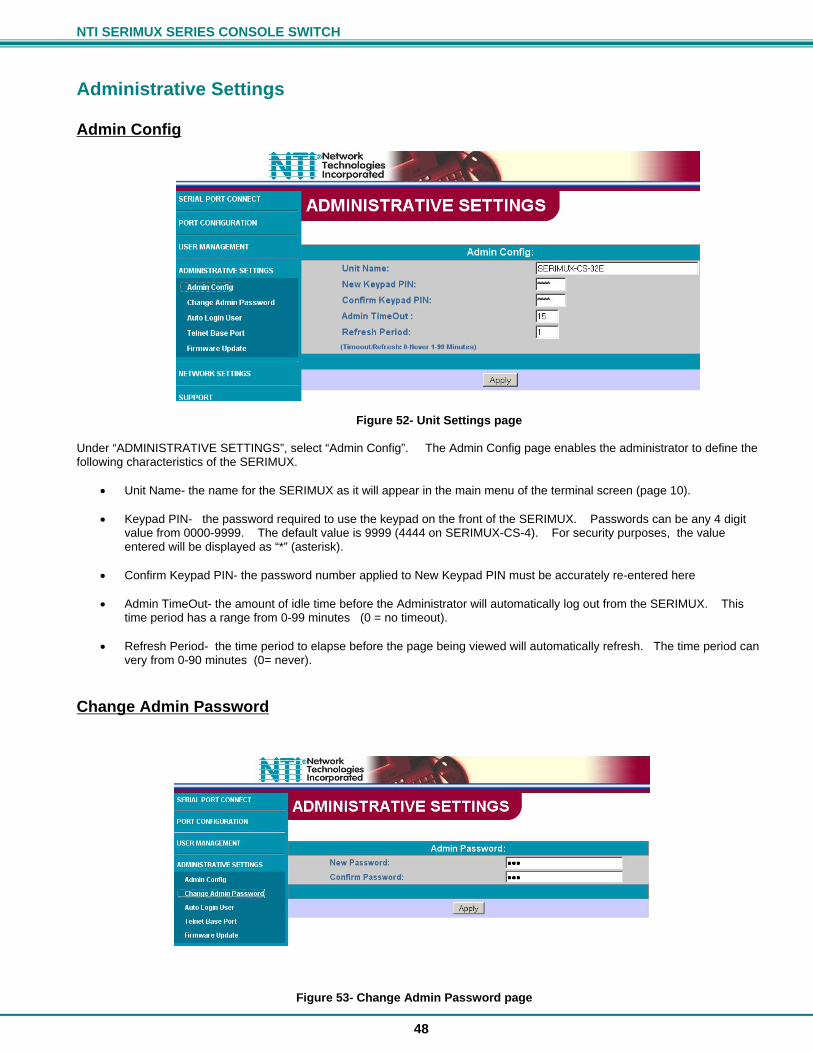
NTI SERIMUX SERIES CONSOLE SWITCH
48
Administrative Settings
Admin Config
Figure 52- Unit Settings page Under “ADMINISTRATIVE SETTINGS”, select “Admin Config”. The Admin Config page enables the administrator to define the following characteristics of the SERIMUX.
Unit Name- the name for the SERIMUX as it will appear in the main menu of the terminal screen (page 10). Keypad PIN- the password required to use the keypad on the front of the SERIMUX. Passwords can be any 4 digit
value from 0000-9999. The default value is 9999 (4444 on SERIMUX-CS-4). For security purposes, the value entered will be displayed as “*” (asterisk).
Confirm Keypad PIN- the password number applied to New Keypad PIN must be accurately re-entered here
Admin TimeOut- the amount of idle time before the Administrator will automatically log out from the SERIMUX. This
time period has a range from 0-99 minutes (0 = no timeout).
Refresh Period- the time period to elapse before the page being viewed will automatically refresh. The time period can very from 0-90 minutes (0= never).
Change Admin Password
Figure 53- Change Admin Password page
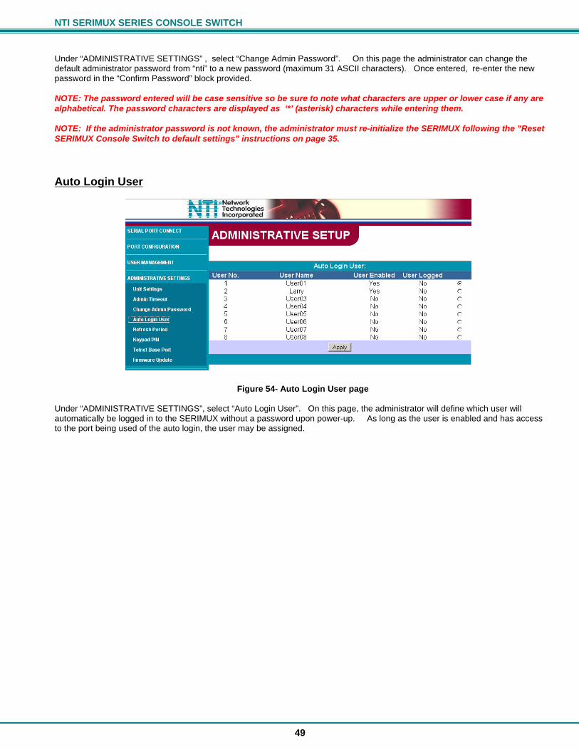
NTI SERIMUX SERIES CONSOLE SWITCH
49
Under “ADMINISTRATIVE SETTINGS” , select “Change Admin Password”. On this page the administrator can change the default administrator password from “nti” to a new password (maximum 31 ASCII characters). Once entered, re-enter the new password in the “Confirm Password” block provided. NOTE: The password entered will be case sensitive so be sure to note what characters are upper or lower case if any are alphabetical. The password characters are displayed as ‘*’ (asterisk) characters while entering them. NOTE: If the administrator password is not known, the administrator must re-initialize the SERIMUX following the "Reset SERIMUX Console Switch to default settings" instructions on page 35.
Auto Login User
Figure 54- Auto Login User page Under “ADMINISTRATIVE SETTINGS”, select “Auto Login User”. On this page, the administrator will define which user will automatically be logged in to the SERIMUX without a password upon power-up. As long as the user is enabled and has access to the port being used of the auto login, the user may be assigned.

NTI SERIMUX SERIES CONSOLE SWITCH
50
Telnet Base Port
Figure 55- Telnet Base Port page Under “ADMINISTRATIVE SETTINGS” , select “Telnet Base Port”. On this page, the administrator will define the base port number used to access the SERIMUX through Telnet. If the base port number is 7000 (the default value), then ports 1-8 would be identified in Telnet as ports 7001 through 7008 respectively. If the base port is changed, to 7125 for example, then ports 1-8 would be identified in Telnet as ports 7126 through 7133 respectively.
Note: Once the Telnet Base Port number is changed, the SERIMUX must be restarted for the new number to take effect.
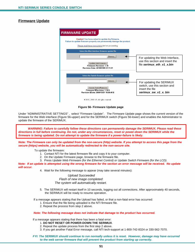
NTI SERIMUX SERIES CONSOLE SWITCH
51
Firmware Update
Figure 56- Firmware Update page Under “ADMINISTRATIVE SETTINGS” , select “Firmware Update”. The Firmware Update page shows the current version of the firmware for the Web interface (Figure 56-upper) and for the SERIMUX switch (Figure 56-lower) and enables the Administrator to update the firmware of the SERIMUX.
WARNING: Failure to carefully follow these directions can permanently damage the SERIMUX. Please read these directions in full before continuing. Do not, under any circumstances, reset or power-down the SERIMUX while the firmware is being updated. Do not attempt to update the firmware if a power-failure is likely. Note: The Firmware can only be updated from the non-secure (http) website. If you attempt to access this page from the secure (https) website, you will be automatically redirected to the non-secure site.
To update the firmware: 1. Contact NTI for the latest firmware file and copy it to your computer. 2. On the Update Firmware page, browse to the firmware file. 3. Press Update Web Firmware (for the Ethernet Control) or Update Switch Firmware (for the LCD).
Note: If an update is attempted using the wrong firmware for the section an error message will be received. No update will occur.
4. Wait for the following message to appear (may take several minutes):
Upload Succeeded Flash of new image completed: The system will automatically restart.
5. The SERIMUX will restart itself in 10 seconds, logging out all connections. After approximately 40 seconds, the SERIMUX will be ready to resume operation.
If a message appears stating that the Upload has failed, or that a non-fatal error has occurred: 1. Ensure that the file being uploaded is the NTI firmware file. 2. Repeat the process from step 2 above. Note: The following message does not indicate that damage to the product has occurred. If a message appears stating that there has been a fatal error: 1. DO NOT RESET OR POWER-DOWN THE SERIMUX. 2. Repeat the update process from the first step 2 above. 3. If you get another Fatal Error message, call NTI tech-support at 1-800-742-8324 or 330-562-7070. FYI: The SERIMUX should continue to run normally unless it is reset. However, damage may have occurred to the web server firmware that will prevent the product from starting up correctly.
For updating the Web Interface, use this section and insert the file serimux_eth_v1_x.bin
For updating the SERIMUX switch, use this section and insert the file serimux_sw_v1_x. bin
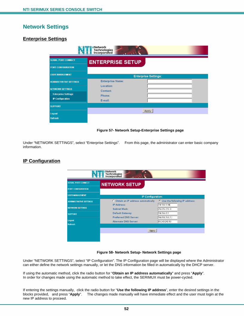
NTI SERIMUX SERIES CONSOLE SWITCH
52
Network Settings
Enterprise Settings
Figure 57- Network Setup-Enterprise Settings page Under “NETWORK SETTINGS”, select “Enterprise Settings”. From this page, the administrator can enter basic company information.
IP Configuration
Figure 58- Network Setup- Network Settings page Under “NETWORK SETTINGS”, select “IP Configuration”. The IP Configuration page will be displayed where the Administrator can either define the network settings manually, or let the DNS information be filled in automatically by the DHCP server. If using the automatic method, click the radio button for “Obtain an IP address automatically” and press “Apply”. In order for changes made using the automatic method to take effect, the SERIMUX must be power-cycled. If entering the settings manually, click the radio button for “Use the following IP address”, enter the desired settings in the blocks provided, and press “Apply”. The changes made manually will have immediate effect and the user must login at the new IP address to proceed.
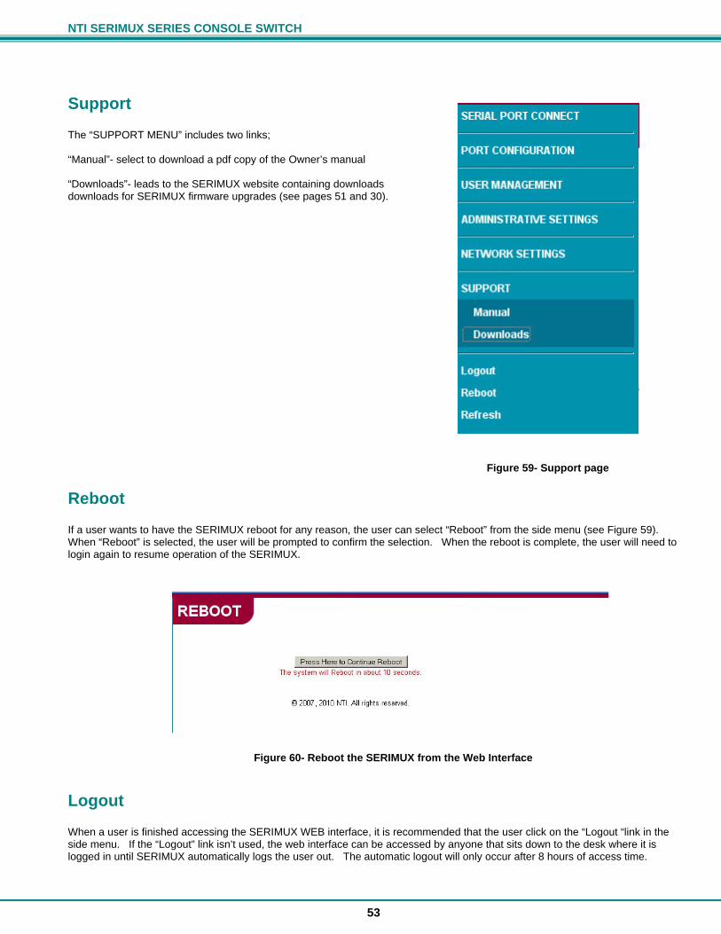
NTI SERIMUX SERIES CONSOLE SWITCH
53
Support The “SUPPORT MENU” includes two links; “Manual”- select to download a pdf copy of the Owner’s manual “Downloads”- leads to the SERIMUX website containing downloads downloads for SERIMUX firmware upgrades (see pages 51 and 30).
Figure 59- Support page
Reboot If a user wants to have the SERIMUX reboot for any reason, the user can select “Reboot” from the side menu (see Figure 59). When “Reboot” is selected, the user will be prompted to confirm the selection. When the reboot is complete, the user will need to login again to resume operation of the SERIMUX.
Figure 60- Reboot the SERIMUX from the Web Interface
Logout When a user is finished accessing the SERIMUX WEB interface, it is recommended that the user click on the “Logout “link in the side menu. If the “Logout” link isn’t used, the web interface can be accessed by anyone that sits down to the desk where it is logged in until SERIMUX automatically logs the user out. The automatic logout will only occur after 8 hours of access time.
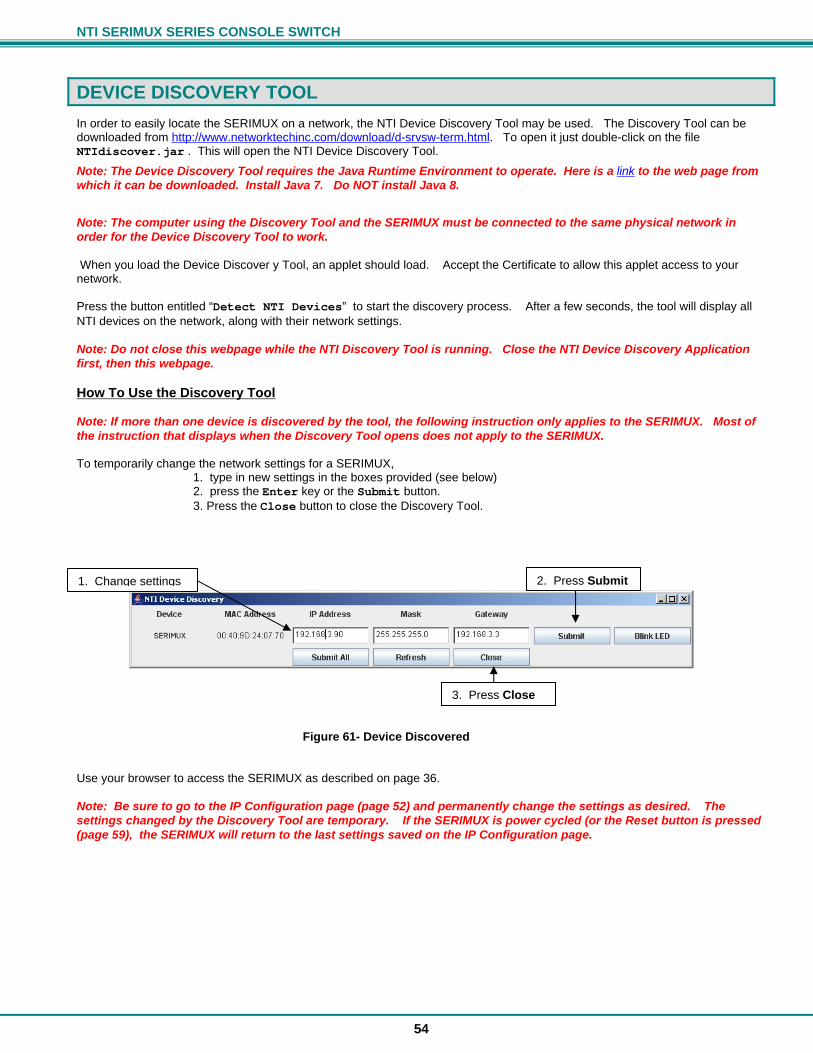
NTI SERIMUX SERIES CONSOLE SWITCH
54
DEVICE DISCOVERY TOOL
In order to easily locate the SERIMUX on a network, the NTI Device Discovery Tool may be used. The Discovery Tool can be downloaded from http://www.networktechinc.com/download/d-srvsw-term.html. To open it just double-click on the file NTIdiscover.jar . This will open the NTI Device Discovery Tool.
Note: The Device Discovery Tool requires the Java Runtime Environment to operate. Here is a link to the web page from which it can be downloaded. Install Java 7. Do NOT install Java 8.
Note: The computer using the Discovery Tool and the SERIMUX must be connected to the same physical network in order for the Device Discovery Tool to work. When you load the Device Discover y Tool, an applet should load. Accept the Certificate to allow this applet access to your network. Press the button entitled “Detect NTI Devices” to start the discovery process. After a few seconds, the tool will display all NTI devices on the network, along with their network settings. Note: Do not close this webpage while the NTI Discovery Tool is running. Close the NTI Device Discovery Application first, then this webpage. How To Use the Discovery Tool Note: If more than one device is discovered by the tool, the following instruction only applies to the SERIMUX. Most of the instruction that displays when the Discovery Tool opens does not apply to the SERIMUX. To temporarily change the network settings for a SERIMUX, 1. type in new settings in the boxes provided (see below) 2. press the Enter key or the Submit button. 3. Press the Close button to close the Discovery Tool.
Figure 61- Device Discovered Use your browser to access the SERIMUX as described on page 36. Note: Be sure to go to the IP Configuration page (page 52) and permanently change the settings as desired. The settings changed by the Discovery Tool are temporary. If the SERIMUX is power cycled (or the Reset button is pressed (page 59), the SERIMUX will return to the last settings saved on the IP Configuration page.
1. Change settings 2. Press Submit
3. Press Close
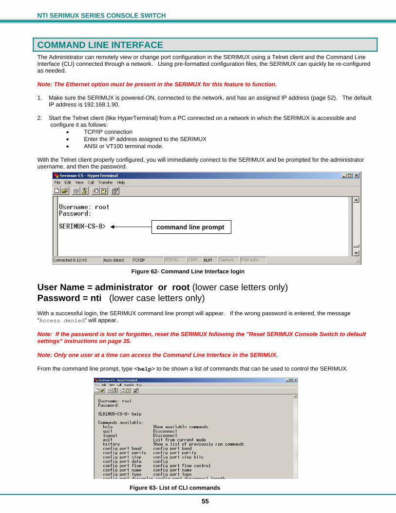
NTI SERIMUX SERIES CONSOLE SWITCH
55
COMMAND LINE INTERFACE The Administrator can remotely view or change port configuration in the SERIMUX using a Telnet client and the Command Line Interface (CLI) connected through a network. Using pre-formatted configuration files, the SERIMUX can quickly be re-configured as needed. Note: The Ethernet option must be present in the SERIMUX for this feature to function. 1. Make sure the SERIMUX is powered-ON, connected to the network, and has an assigned IP address (page 52). The default IP address is 192.168.1.90. 2. Start the Telnet client (like HyperTerminal) from a PC connected on a network in which the SERIMUX is accessible and configure it as follows:
TCP/IP connection Enter the IP address assigned to the SERIMUX ANSI or VT100 terminal mode.
With the Telnet client properly configured, you will immediately connect to the SERIMUX and be prompted for the administrator username, and then the password.
Figure 62- Command Line Interface login
User Name = administrator or root (lower case letters only) Password = nti (lower case letters only) With a successful login, the SERIMUX command line prompt will appear. If the wrong password is entered, the message “Access denied” will appear. Note: If the password is lost or forgotten, reset the SERIMUX following the "Reset SERIMUX Console Switch to default settings" instructions on page 35. Note: Only one user at a time can access the Command Line Interface in the SERIMUX. From the command line prompt, type <help> to be shown a list of commands that can be used to control the SERIMUX.
Figure 63- List of CLI commands
command line prompt
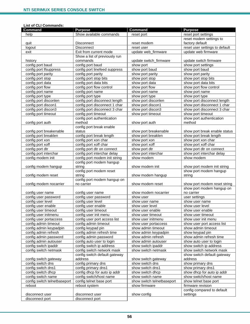
NTI SERIMUX SERIES CONSOLE SWITCH
56
List of CLI Commands: Command Purpose Command Purpose help Show available commands reset port reset port settings
quit Disconnect reset modem reset modem settings to factory default
logout Disconnect reset user reset user settings to default exit Exit from current mode update web_firmware update web firmware
history Show a list of previously run commands update switch_firmware update switch firmware
config port baud config port baud show port show port settings config port lfsuppress config port linefeed suppress show port baud show port baud config port parity config port parity show port parity show port parity config port stop config port stop bits show port stop show port stop bits config port data config port data bits show port data show port data bits config port flow config port flow control show port flow show port flow control config port name config port name show port name show port name config port type config port type show port type show port type config port disconlen config port disconnect length show port disconlen show port disconnect length config port discon1 config port disconnect 1 char show port discon1 show port disconnect 1 char config port discon3 config port disconnect 3 char show port discon3 show port disconnect 3 char config port timeout config port timeout show port timeout show port timeout
config port auth config port authentication method show port auth
show port authentication method
config port breakenable config port break enable status show port breakenable show port break enable status
config port breaklen config port break length show port breaklen show port break length config port xon config port xon char show port xon show port xon char config port xoff config port xoff char show port xoff show port xoff char config port dtr config port dtr on connect show port dtr show port dtr on connect config port interchar config port interchar delay show port interchar show port interchar delay config modem init config port modem init string show modem show modem
config modem hangup config port modem hangup string show modem init show port modem init string
config modem reset config port modem reset string show modem hangup
show port modem hangup string
config modem nocarrier config port modem hangup on no carrier show modem reset show port modem reset string
config user name config user name show modem nocarrier show port modem hangup on no carrier
config user password config user password show user user settings config user level config user level show user name show user name config user enable config user enable show user level show user level config user timeout config user timeout show user enable show user enable config user initmenu config user init menu show user timeout show user timeout config user portaccess config user port access list show user initmenu show user init menu config admin timeout config admin timeout show user portaccess show user port access list config admin keypadpin config keypad pin show admin timeout show admin timeout config admin refresh config admin refresh time show admin keypadpin show keypad pin config admin password config admin password show admin refresh show admin refresh time config admin autouser config auto user to login show admin autouser show auto user to login config switch ipaddr config switch ip address show switch ipaddr show switch ip address config switch netmask config switch network mask show switch netmask show switch network mask
config switch gateway config switch default gateway address show switch gateway
show switch default gateway address
config switch dns config primary dns show switch dns show primary dns config switch dns1 config primary dns1 show switch dns1 show primary dns1 config switch dhcp config dhcp for auto ip addr show switch dhcp show dhcp for auto ip addr config switch name config switch/host name show switch name show switch/host name config switch telnetbaseport config telnet base port show switch telnetbaseport show telnet base port reboot reboot system show firmware firmware revision
disconnect user disconnect user show config config compared to default settings
disconnect port disconnect port
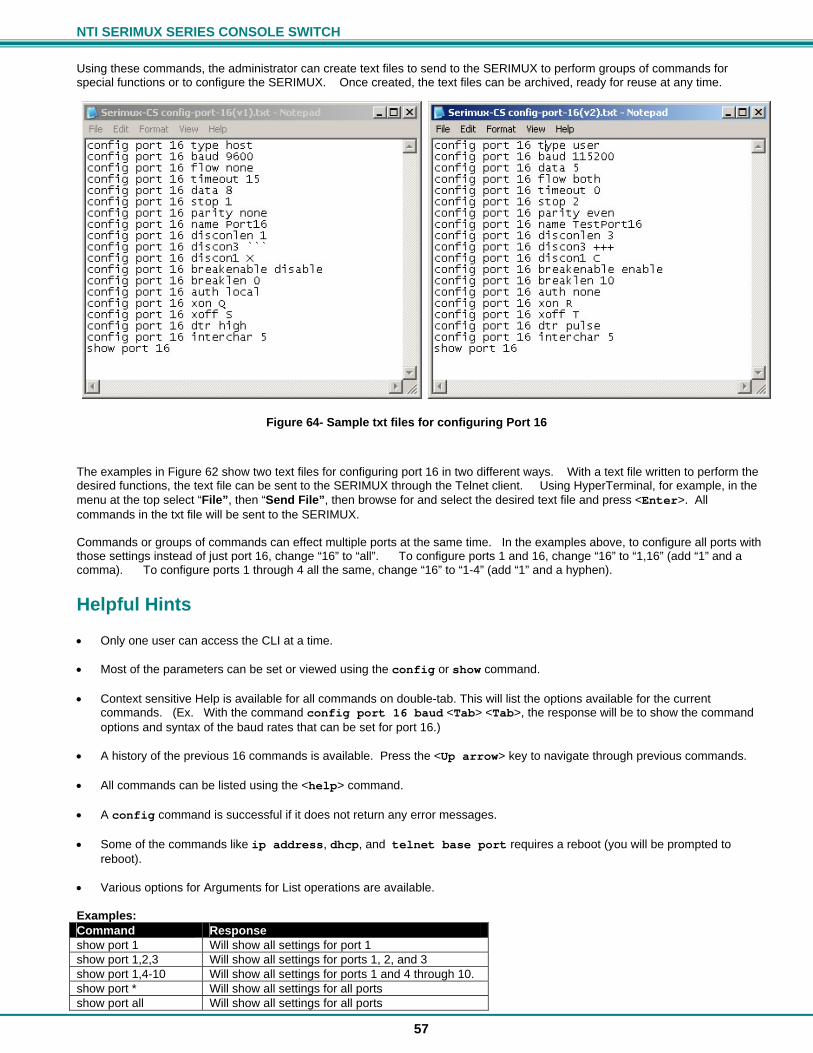
NTI SERIMUX SERIES CONSOLE SWITCH
57
Using these commands, the administrator can create text files to send to the SERIMUX to perform groups of commands for special functions or to configure the SERIMUX. Once created, the text files can be archived, ready for reuse at any time.
Figure 64- Sample txt files for configuring Port 16
The examples in Figure 62 show two text files for configuring port 16 in two different ways. With a text file written to perform the desired functions, the text file can be sent to the SERIMUX through the Telnet client. Using HyperTerminal, for example, in the menu at the top select “File”, then “Send File”, then browse for and select the desired text file and press <Enter>. All commands in the txt file will be sent to the SERIMUX. Commands or groups of commands can effect multiple ports at the same time. In the examples above, to configure all ports with those settings instead of just port 16, change “16” to “all”. To configure ports 1 and 16, change “16” to “1,16” (add “1” and a comma). To configure ports 1 through 4 all the same, change “16” to “1-4” (add “1” and a hyphen).
Helpful Hints Only one user can access the CLI at a time. Most of the parameters can be set or viewed using the config or show command. Context sensitive Help is available for all commands on double-tab. This will list the options available for the current
commands. (Ex. With the command config port 16 baud <Tab> <Tab>, the response will be to show the command options and syntax of the baud rates that can be set for port 16.)
A history of the previous 16 commands is available. Press the <Up arrow> key to navigate through previous commands. All commands can be listed using the <help> command. A config command is successful if it does not return any error messages. Some of the commands like ip address, dhcp, and telnet base port requires a reboot (you will be prompted to
reboot). Various options for Arguments for List operations are available. Examples: Command Response show port 1 Will show all settings for port 1 show port 1,2,3 Will show all settings for ports 1, 2, and 3 show port 1,4-10 Will show all settings for ports 1 and 4 through 10. show port * Will show all settings for all ports show port all Will show all settings for all ports
NTI SERIMUX SERIES CONSOLE SWITCH
58
Update Firmware from CLI In addition to being able to update the firmware using the Web Interface (page 51) or the menus in Serial Control (page 30), the firmware for the SERIMUX can also be updated from the CLI. 1. Place the new firmware files (both web and switch) on a host machine with a tftp server running. (Names of the files can be changed to whatever is suitable.) 2. From the command line issue commands to update web and switch firmware respectively. Format: update web_firmware %host_ip_addr% %file_name% update switch_firmware %host_ip_addr% %file_name% The firmware file is downloaded to the SERIMUX and written to flash memory. This may take up to 5-10 minutes. System will go to auto reboot within 10 seconds of each completed update. Example: IP address of Host on which the tftp server is running : 192.168.3.151 Web firmware filename : serimuxweb_update.bin Switch firmware filename : serimuxswitch_update.bin Note: These are the same files referred to in the Web Interface Firmware Update section (page 51). 1) For web interface command -> update web_firmware 192.168.3.151 serimuxweb_update.bin Response -> Please wait while updating web firmware. Response -> Web Firmware update successful. System will now reboot. 2) For switch firmware command -> command -> update switch_firmware 192.168.3.151 serimuxswitch_update.bin Response -> Please wait while updating switch firmware. Response -> Switch Firmware update successful. System will now reboot.
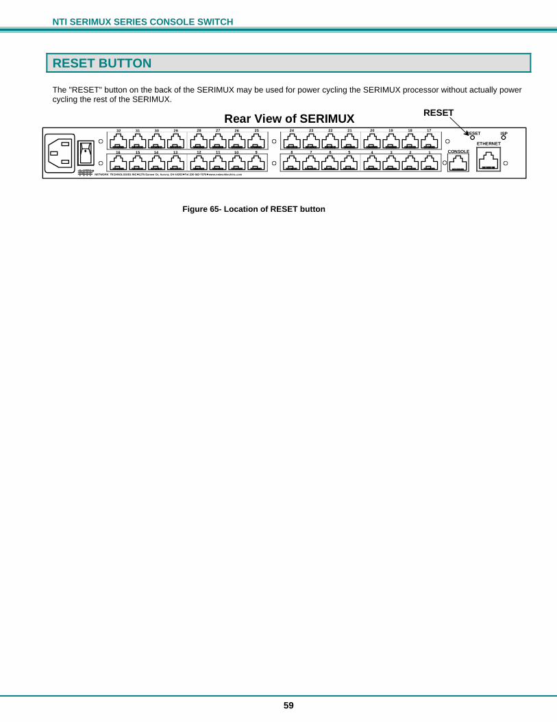
NTI SERIMUX SERIES CONSOLE SWITCH
59
RESET BUTTON The "RESET" button on the back of the SERIMUX may be used for power cycling the SERIMUX processor without actually power cycling the rest of the SERIMUX.
Figure 65- Location of RESET button
Rear View of SERIMUX
CONSOLE910111213141516 12345678
2526272829303132 21222324 17181920RESET ISP
ETHERNET
NETWORK TECHNOLOGIES INC Tel:330-562-70701275 Danner Dr, Aurora, OH 44202 www.networktechinc.comNTI R
RESET
NTI SERIMUX SERIES CONSOLE SWITCH
60
INTERCONNECTION CABLE WIRING METHOD The cable connecting the terminals and devices to the SERIMUX must be terminated with RJ45 connectors and must be wired according to the EIA/TIA 568 B industry standard. Wiring is as per the table and drawing below. Pin Wire Color Pair Function 1 White/Orange 2 T 2 Orange 2 R 3 White/Green 3 T 4 Blue 1 R 5 White/Blue 1 T 6 Green 3 R 7 White/Brown 4 T 8 Brown 4 R
Figure 66- View looking into RJ45 female
TROUBLESHOOTING If the Console Switch is not working properly, consider the suggestions below to see if a solution can be found.
Problem Cause Solution No Front Panel LEDs are illuminated No power to SERIMUX Check all power connections SERIMUX is not working properly Poor Connections
Port not configured correctly Ports not initialized
Verify that all cables are securely connected
Verify that the port configuration matches that of the device connected
Power-up the CPUs first, then the SERIMUX
Cannot Connect to port/device Port settings not correct Wrong cable adapter used Connections are loose Wrong serial cable pinout
Verify proper communication settings (page 8)
Verify that adapter is one specified in Appendix C.
Verify that all cable connections are secure
If using straight-thru connections, try a crossover cable (RJ45MF-RS232-CO); If crossover, try a straight through serial connection. See page 6.
Commands entered from front panel keypad are not accepted
Buttons are being pressed too rapidly 1) Make sure the Keypad PIN is entered properly.
2) Press the “Enter” key before typing the PIN to discard the previous entry.
3) Try the PIN again but slow down the button sequence- approx 1/2 sec between each press.
SERIMUX will not accept username or password
Usernames and passwords are case sensitive
Verify characters used and enter again.
Cannot access user menu on a port Port is configured as host port Configure port as user port. (page 40) I cannot access the View Port Data Buffer
Only the ROOT user can access this (see page 17)
Login as the ROOT user
If the passwords or other important parameters are not available, the SERIMUX Console Switch can be re-initialized to the default settings (see "Initialize SERIMUX Console Switch to default settings" on page 35).
Caution: During initialization, the customer modified parameter values will be replaced with the factory default values; all ports will be placed in buffer mode; all passwords will be erased.
If the suggestions above have been tried and the NTI Console Switch is still not functioning properly, a solution to the problem may be found on our website at http://www.networktechinc.com in our FAQ (Frequently Asked Questions) section, or, please call us directly at (800) 742-8324 (800-RGB-TECH) in the US & Canada or (330) 562-7070 (Worldwide) and we’ll be happy to assist in any way we can.
T
1+
R
2-
T
3+
R
4-
T
5+
R
6-
T
7+
R
8-
Pair 2 Pair 1 Pair 4
Pair 3
NTI SERIMUX SERIES CONSOLE SWITCH
61
Appendix A - SERIMUX Port Characteristics Every port is defined through the following parameters: Description Acceptable Value Default Value Number 0-8/16/24/32 Same (not changeable) Name Up to 15 characters “Port00” to “Port32” Type – port 0 User User (not changeable) Type – except port 0 User or Host Host Baud rate – port 0 300-115200 9600 Baud rate – except port 0 50-128000 9600 Data bits per character – port 0 7,8 8 Data bits per character – except port 0 5,6,7,8 8 Stop bits – port 0 1, 2 1 Stop bits – except port 0 1, 1-1/2, 2 1 Parity No parity, even, odd No parity Handshake mode (flow control) Xon / Xoff (or in-band, or software),
RTS/CTS (or out-band or hardware), Both, None
None
Xon character any ASCII nonprintable character (0-31 range) Ctrl+Q (17) Xoff character any ASCII nonprintable character (0-31 range) Ctrl+S (19) Inter-character delay – except port 0 (no delay allowed on port 0)
1-60 milliseconds, none None
Line break receive allowance – except port 0 (no allowance for port 0)
Yes or No No
Transmitted line break extra duration (added to 1 character transmission time) – except port 0 (no extra duration for port 0)
No break transmitted, 1-999 milliseconds No break transmitted
In-band disconnect sequence 0 (disabled), 1, or 3 characters sequence 1-char sequence
1 character disconnect sequence Any ASCII nonprintable character (0-31 range) Ctrl+X (24) 3 character disconnect sequence Any 3 ASCII characters ``` (3 back quotes) Connection timeout 1-90 minutes, never 15 minutes DTR output upon disconnect Low, high, or pulsed for 0.5 seconds and then held
high High
Modem Reset string Up to 41 characters ATZ Modem Initialization string Up to 41 characters AT&F&C1&D2S0=0 Modem Disconnect string Up to 41 characters ATH Appendix B - SERIMUX User and Administrator Characteristics The users and the administrator are defined through the following parameters: Description Acceptable Value Default Value Users: User number 1 to 32 Same (not changeable) User name Up to 15 characters – case sensitive “User01” to “User32” User password Up to 31 characters – case sensitive “” (empty string) User enabled Yes or No Not enabled, except
User 1: enabled Administrative privileges Yes or No No Access to ports Port 0 always; Ports 1-31 Port 0, except
User 1: all ports User menu timeout 1-90 minutes, never 15 minutes Administrator: Administrator name “ADMINISTRATOR” or “ROOT” – case sensitive Same (not changeable) Administrator password Up to 31 characters – case sensitive “NTI” Administrator menu timeout 1-90 minutes, never 15 minutes User to auto login User 1-32, None User 1
NTI SERIMUX SERIES CONSOLE SWITCH
62
Appendix C- Cable Adapters Four cable adapters are included with the SERIMUX with RJ45 connectors (to purchase more please contact NTI at (800) 742-8324 (800-RGB-TECH) or (330) 562-7070). The following illustrations show cable adapter pin outs. DB-25 Male Console Adapter (NTI P/N DB25M-RJ45F-T)
DB-25 Male to RJ45 Connector Pin Assignments
RJ45 Signal DB-25M Signal 1 CTS Connected to 4 RTS 2 DSR 5 DCD
Connected to 20 DTR
3 RxD Connected to 2 TxD
4 GND Connected to 7 GND
6 TxD Connected to 3 RxD 6 DCD
7 DTR Connected to 8 DSR
8 RTS Connected to 5 CTS
DB-9 Female Console Adapter (NTI P/N DB9F-RJ45F) DB-9 Female to RJ45 Pin Assignments
RJ45 Signal DB-9F Signal 1 CTS Connected to 7 RTS 2 DSR 5 DCD
Connected to 4 DTR
3 RxD Connected to 3 TxD 4 GND Connected to 5 GND 6 TxD Connected to 2 RxD
1 DCD 7 DTR Connected to
6 DSR 8 RTS Connected to 8 CTS
NTI SERIMUX SERIES CONSOLE SWITCH
63
DB-25 Female Console Adapter (NTI P/N DB25F-RJ45F) DB-25 Female to RJ45 Pin Assignments
RJ45 Signal DB-25F Signal 1 CTS Connected to 4 RTS 2 DSR 5 DCD
Connected to 20 DTR
3 RxD Connected to 2 TxD 4 GND Connected to 7 GND 6 TxD Connected to 3 RxD
6 DCD 7 DTR Connected to
8 DSR 8 RTS Connected to 5 CTS DB-25 Male Modem Adapter (NTI P/N DB25M-RJ45F-C)
DB-25 Male Modem to RJ45 Pin Assignment
RJ45 Signal DB-25M Signal 1 CTS Connected to 5 CTS 2 DSR Connected to 6 DSR 3 RxD Connected to 3 RxD 4 GND Connected to 7 GND 5 DCD Connected to 8 DCD 6 TxD Connected to 2 TxD
7 DTR Connected to 20 DTR
8 RTS Connected to 4 RTS
NTI SERIMUX SERIES CONSOLE SWITCH
64
Ethernet Pinouts The SERIMUX with RJ45 connectors uses a standard Ethernet connector that is a shielded and compliant with AT&T 258 specifications.
SPECIFICATIONS DESCRIPTION SPECIFICATION Connectors RJ45 Female DTE configuration via RS232 Operating temperature 32°F - 100°F (0°C - 38°C) (17-90% non-condensing RH) Storage temperature -20°F - 140°F (-30°C - 60°C). (17-90% non-condensing RH) Power requirements 100-240VAC, 50 or 60Hz Size (In.) WxDxH 15.25x6x1.75 without rack ears mounted
19x6x1.75 with rack ears mounted
Pin Description 1 Tx+ 2 Tx- 3 Rx+ 4 NC 5 NC 6 Rx- 7 NC 8 NC
NTI SERIMUX SERIES CONSOLE SWITCH
65
INDEX Accessible host list, 25 Administrative settings, 48 Advanced settings, 21, 24 ANSI, 1 cable adapters, 62 cable connections, 6 Change Admin Password, 49 clear port buffer, 40 CLI commands list, 56 Command line interface, 55 connect two host ports, 39 copy port settings, 44 definitions, 2 Device Discovery Tool, 54 disconnect port, 39 disconnect user, 45 Dual Power, 7 Enterprise settings, 52 Ethernet connection, 6 Firmware menu, 22, 23 Firmware upgrade, 30, 51 interconnection cable, 60 IP address, 36 IP configuration, 52 ISP button, 4 Java, 54 Keypad control, 9, 32 Keypad PIN, 3, 9, 21, 48 LAN, 36 login, 9, 10 Main menu, 10
modem settings, 16, 43 network settings, 23, 52 password, 3, 9, 36 Password-change, 21, 23 port access, 20 port configuration, 38 Port List, 11 port settings, 13, 41 Quick start, 8 rack mounting, 5 reboot, 24, 53 serial communications, 9 Serial Control, 9 serial port characteristics, 61 serial port connect, 37 serial settings, 42 telnet base port, 50 Telnet connection, 37 terse mode, 19, 28 Troubleshooting, 60 User main menu, 26 user name, 3 User port list, 27 User serial controls, 25 User settings, 19 username and password, 36 view user list, 45 VT100, 1 web browsers, 2 Web Interface, 36
WARRANTY INFORMATION The warranty period on this product (parts and labor) is two (2) years from the date of purchase. Please contact Network Technologies Inc at (800) 742-8324 (800-RGB-TECH) or (330) 562-7070 or visit our website at http://www.networktechinc.com for information regarding repairs and/or returns. A return authorization number is required for all repairs/returns.
Man088 Rev 4/26/17