connecting the cisco rps · pdf filethe catalyst 1900 series and catalyst 2820 series switches...
TRANSCRIPT

Cisco Redundant PowOL-3654-01
C H A P T E R 4
adynyRPS
ubAC
Connecting the Cisco RPS
This chapter provides instructions on connecting your external device to theCisco RPS. The chapter is divided into the following major sections:
• Power Considerations, page 4-1
• Connecting Hubs, page 4-3
• Connecting Switches, page 4-7
• Connecting Routers and the Cisco MC3810 Concentrator, page 4-13
Power ConsiderationsBefore connecting to external devices, read the power warnings below. Werecommend that you disconnect all power before beginning.
Note If you want to connect an additional external device to a Cisco RPS that is alrepowered up, you can do so without interrupting power to the Cisco RPS or aother connected external devices. Be sure to connect your cable to the Ciscofirst and then to the external device. However, in a redundant-with-rebootconfiguration, to ensure proper operation, you must power up the switch or hbefore powering up the Cisco RPS. Therefore, always connect the switch to power before you connect it to the Cisco RPS. Failure to follow the properpower-up sequence can result in incorrect LED displays.
4-1er System Hardware Installation Guide

Chapter 4 Connecting the Cisco RPSPower Considerations
er.
led
Note A catalyst switch might reload when changing from RPS power to internal powThis can occur on any catalyst switch, except the 3560-E or 3750-E switch,connected to one of the following: Redundant, Power Supplies, PWR300-AC-RPS-NI, PWR-600-AC-RPS-NI, and RPS2300. To prevent unschedudowntime, the switch should be powered off during a maintenance window.
Warning Attach only the Cisco RPS (model PWR600-AC-RPS) to the RPS receptacle. Tosee translations of the warnings that appear in this publication, refer to theRegulatory Compliance and Safety Information document that accompanied thisdevice.
Warning Before performing any of the following procedures, ensure that power isremoved from the DC circuit. To ensure that all power is OFF, locate the circuitbreaker on the panel board that services the DC circuit, switch the circuitbreaker to the OFF position, and tape the switch handle of the circuit breaker inthe OFF position. To see translations of the warnings that appear in thispublication, refer to the Regulatory Compliance and Safety Informationdocument that accompanied this device.
Warning Before working on a system that has an on/off switch, turn OFF the power andunplug the power cord. To see translations of the warnings that appear in thispublication, refer to the Regulatory Compliance and Safety Informationdocument that accompanied this device.
Warning This unit might have more than one power cord. To reduce the risk of electricshock, disconnect the two power supply cords before servicing the unit. To seetranslations of the warnings that appear in this publication, refer to theRegulatory Compliance and Safety Information document that accompanied thisdevice.
4-2Cisco Redundant Power System Hardware Installation Guide
OL-3654-01

Chapter 4 Connecting the Cisco RPSConnecting Hubs
eries
ore of
not
hub
own
Connecting HubsThis section provides illustrations and cabling information for connecting theCisco RPS to the following hubs:
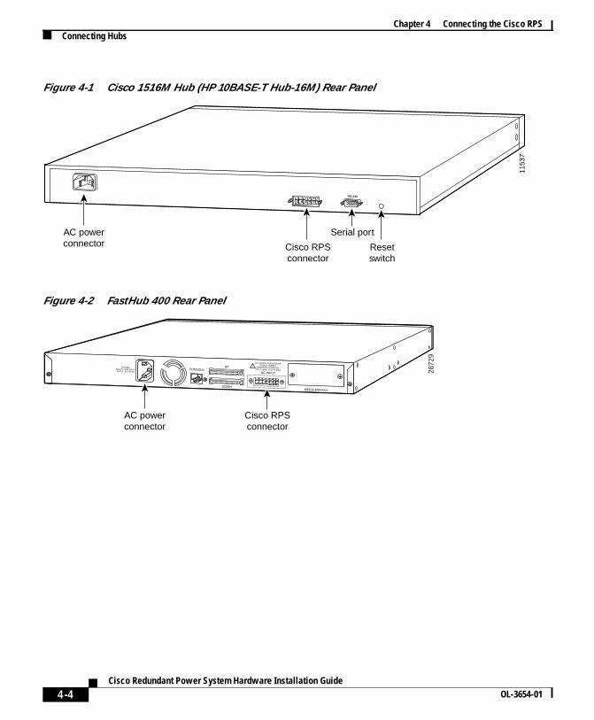
• Cisco 1516M hub (HP 10BASE-T Hub-16M) (Figure 4-1)
• FastHub 400 series hubs (Figure 4-2)
Note The Cisco RPS can also be used with the older FastHub 100, 200, and 300 shubs.
All hubs can use the one-to-one cable configuration for quasi-redundancy. TheFastHub 400 series also supports the option of connecting the AC power cord fredundancy with reboot, although this configuration is not recommended. The usa Y-cable for full redundancy is not supported.
The HP 10BASE-T Hub-16M does not support redundancy with reboot and doessupport use of the Y-cable for full redundancy.
To connect hubs to the Cisco RPS, perform these steps:
Step 1 Disconnect the AC power cord on the hub.
Step 2 Connect one end of the one-to-one cable to the Cisco RPS connector on therear panel. (For connector locations, seeFigure 4-1 andFigure 4-2.)
Step 3 Connect the other end of the cable to a Cisco RPS rear-panel connector as shin Figure 4-3.
4-3Cisco Redundant Power System Hardware Installation Guide
OL-3654-01
Chapter 4 Connecting the Cisco RPSConnecting Hubs
Figure 4-1 Cisco 1516M Hub (HP 10BASE-T Hub-16M) Rear Panel
Figure 4-2 FastHub 400 Rear Panel
1153
7
RS-232
Serial port
Cisco RPSconnector
Resetswitch
AC powerconnector
RATING100-127 / 200-240 V~
2A /1A 50 / 60 HzCONSOLE
UP
MEDIA MODULEDOWN
DC INPUT
DC INPUTS FOR REMOTEPOWER SUPPLY
SPECIFIED IN MANUAL+5V @6A, +12V @1A
AC powerconnector
Cisco RPSconnector
2872
9
Allass
4-4Cisco Redundant Power System Hardware Installation Guide
OL-3654-01
Chapter 4 Connecting the Cisco RPSConnecting Hubs
thein
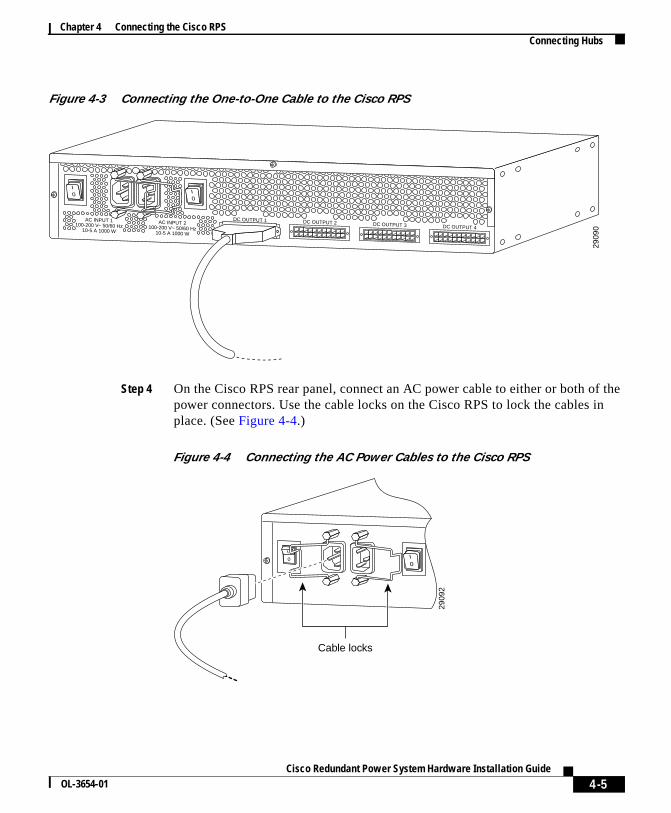
Figure 4-3 Connecting the One-to-One Cable to the Cisco RPS
Step 4 On the Cisco RPS rear panel, connect an AC power cable to either or both ofpower connectors. Use the cable locks on the Cisco RPS to lock the cables place. (SeeFigure 4-4.)
Figure 4-4 Connecting the AC Power Cables to the Cisco RPS
2909
0
AC INPUT 1100-200 V~ 50/60 Hz
10-5 A 1000 W
AC INPUT 2100-200 V~ 50/60 Hz
10-5 A 1000 W
DC OUTPUT 1 DC OUTPUT 2 DC OUTPUT 3 DC OUTPUT 4
2909
2
Cable locks
4-5Cisco Redundant Power System Hardware Installation Guide
OL-3654-01
Chapter 4 Connecting the Cisco RPSConnecting Hubs
tlet.
,let.
he
r
not
Step 5 Connect the other end of the Cisco RPS AC power cable into an AC power ou
Step 6 If you are using the redundant-with-reboot configuration (not recommended)power up the switch by connecting the hub AC power cord to an AC power out
Note If you use the redundant-with-reboot configuration, always power up thubbefore you power up the Cisco RPS.
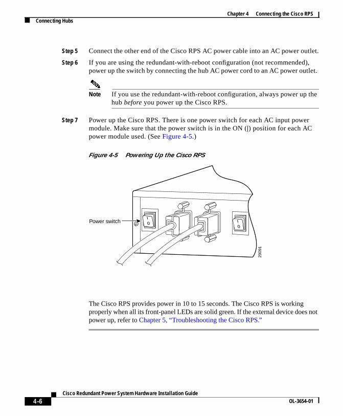
Step 7 Power up the Cisco RPS. There is one power switch for each AC input powemodule. Make sure that the power switch is in the ON (|) position for each ACpower module used. (SeeFigure 4-5.)
Figure 4-5 Powering Up the Cisco RPS
The Cisco RPS provides power in 10 to 15 seconds. The Cisco RPS is workingproperly when all its front-panel LEDs are solid green. If the external device doespower up, refer toChapter 5, “Troubleshooting the Cisco RPS.”
2909
1
Power switch
4-6Cisco Redundant Power System Hardware Installation Guide
OL-3654-01
Chapter 4 Connecting the Cisco RPSConnecting Switches
900
ncy
itch
Connecting SwitchesThe Catalyst 1900 series and Catalyst 2820 series switches and the Catalyst 2series and Catalyst 3500 series XL switches can use:
• One-to-one cable for quasi-redundancy
or
• One-to-one cable with the switch AC power cable connected for redundawith reboot (not recommended)
To connect switches to the Cisco RPS, perform these steps:
Step 1 Disconnect the AC power cord on the switch.
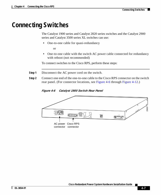
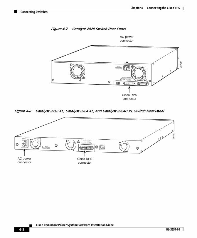
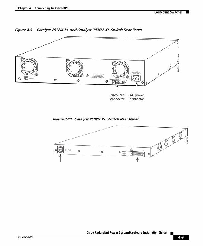
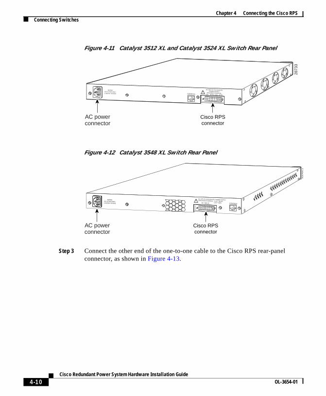
Step 2 Connect one end of the one-to-one cable to the Cisco RPS connector on the swrear panel. (For connector locations, seeFigure 4-6 throughFigure 4-12.)
Figure 4-6 Catalyst 1900 Switch Rear Panel
2908
7
DC INPUTFOR REMOTE
POWER SUPPLYSPECIFIED
IN MANUAL. +5V @6A
+12V @1A
AUICONSOLE
RATING100-127V~
@0.6A200-240V~
@0.3A50-60Hz
AC powerconnector
Cisco RPSconnector
4-7Cisco Redundant Power System Hardware Installation Guide
OL-3654-01
Chapter 4 Connecting the Cisco RPSConnecting Switches
Figure 4-7 Catalyst 2820 Switch Rear Panel
Figure 4-8 Catalyst 2912 XL, Catalyst 2924 XL, and Catalyst 2924C XL Switch Rear Panel
DC INPUTS
RATING100-127/200-240 V~2.0A/1.0A 50/60Hz
AUICONSOLE PORT
2873
0
AC powerconnector
Cisco RPSconnector
DC INPUTS FOR REMOTEPOWER SUPPLY SPECIFIEDIN MANUAL. +5V @ 14A,+12V @ 1A, -12V @ 1A
2873
1
Cisco RPSconnector
AC powerconnector
RATING100-127/200-240V~1.0A/O.5A 50-80HZ
DC INPUTS FOR REMOTEPOWER SUPPLY
SPECIFIED IN MANUAL+5V @9A, +12V @0.5A
CONSOLE
4-8Cisco Redundant Power System Hardware Installation Guide
OL-3654-01
Chapter 4 Connecting the Cisco RPSConnecting Switches
Figure 4-9 Catalyst 2912M XL and Catalyst 2924M XL Switch Rear Panel
Figure 4-10 Catalyst 3508G XL Switch Rear Panel
2873
2
Cisco RPSconnector
AC powerconnector
CONSOLE DC INPUT
DC INPUTS FOR REMOTEPOWER SUPPLY
SPECIFIED IN MANUAL.+5V @24A, +12V @1.0A
RATING100-120/200-240V2.0A/1.0A 50-60HZ
~
2908
8
AC powerconnector
Cisco RPSconnector
DC INPUTS FOR REMO TE POWER SUPPL YSPECIFIED IN MANU AL. +3.3V***@14A, +12V***@3ACONSOLE DC INPUT
RATING100-127/200-2 40V~1.0A/0.5A 50-60HZ
4-9Cisco Redundant Power System Hardware Installation Guide
OL-3654-01
Chapter 4 Connecting the Cisco RPSConnecting Switches
Figure 4-11 Catalyst 3512 XL and Catalyst 3524 XL Switch Rear Panel
Figure 4-12 Catalyst 3548 XL Switch Rear Panel
Step 3 Connect the other end of the one-to-one cable to the Cisco RPS rear-panelconnector, as shown inFigure 4-13.
2873
3
AC powerconnector
Cisco RPSconnector
DC INPUTS FOR REMOTEPOWER SUPPLY
SPECIFIED IN MANUAL.+5V @24A, +12V @.5A
RATING100-127/200-240V~1.0A/0.5A 50-60HZ CONSOLE
2873
4
AC powerconnector
Cisco RPSconnector
DC INPUTS FOR REMOTE POWER SUPPLYSPECIFIED IN MANUAL. +3.3V***@14A,+12V***@3A CONSOLEDC INPUT
RATING100-127/200-240V~1.0A/0.5A 50-60HZ
4-10Cisco Redundant Power System Hardware Installation Guide
OL-3654-01
Chapter 4 Connecting the Cisco RPSConnecting Switches
thein
tlet.
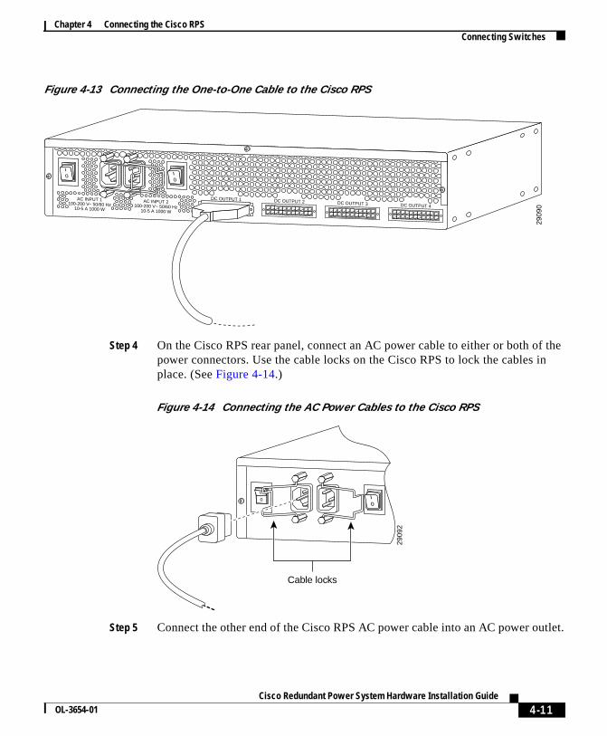
Figure 4-13 Connecting the One-to-One Cable to the Cisco RPS
Step 4 On the Cisco RPS rear panel, connect an AC power cable to either or both ofpower connectors. Use the cable locks on the Cisco RPS to lock the cables place. (SeeFigure 4-14.)
Figure 4-14 Connecting the AC Power Cables to the Cisco RPS
Step 5 Connect the other end of the Cisco RPS AC power cable into an AC power ou
2909
0
AC INPUT 1100-200 V~ 50/60 Hz
10-5 A 1000 W
AC INPUT 2100-200 V~ 50/60 Hz
10-5 A 1000 W
DC OUTPUT 1 DC OUTPUT 2 DC OUTPUT 3 DC OUTPUT 4
2909
2
Cable locks
4-11Cisco Redundant Power System Hardware Installation Guide
OL-3654-01
Chapter 4 Connecting the Cisco RPSConnecting Switches
,er
he
tle is
not
lystD
he
Step 6 If you are using the redundant-with-reboot configuration (not recommended)power up the switch by connecting the switch AC power cord into an AC powoutlet.
Note If you use the redundant-with-reboot configuration, always power up tswitchbefore you power up the Cisco RPS.
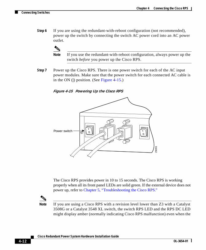
Step 7 Power up the Cisco RPS. There is one power switch for each of the AC inpupower modules. Make sure that the power switch for each connected AC cabin the ON (|) position. (SeeFigure 4-15.)
Figure 4-15 Powering Up the Cisco RPS
The Cisco RPS provides power in 10 to 15 seconds. The Cisco RPS is workingproperly when all its front panel LEDs are solid green. If the external device doespower up, refer toChapter 5, “Troubleshooting the Cisco RPS.”
Note If you are using a Cisco RPS with a revision level lower than Z3 with a Cata3508G or a Catalyst 3548 XL switch, the switch RPS LED and the RPS DC LEmight display amber (normally indicating Cisco RPS malfunction) even when t
2909
1
Power switch
4-12Cisco Redundant Power System Hardware Installation Guide
OL-3654-01

Chapter 4 Connecting the Cisco RPSConnecting Routers and the Cisco MC3810 Concentrator
o
our
ped
the
Cisco RPS is functioning properly. The LEDs display correctly for Cisco RPSrevision level Z3 or later revision. The label on the bottom of the Cisco RPSshows the revision level.
Connecting Routers and the Cisco MC3810Concentrator
This section provides illustrations and cabling information for connecting theCisco RPS to Cisco 2500 series andCisco 2600 series routers; Cisco 3620, Cisc3640, and Cisco 3725 routers; Cisco 4000series routers and Cisco MC3810multiservice concentrators. All these devices use:
• One-to-one cable for quasi-redundancy
or
• Two-to-one Y-cable for full redundancy
Note If you did not order your router or concentrator with a Cisco RPS connectorinstalled, you must order a power adapter plate and must install it in place of yexisting power supply.
If you need to order a power adapter plate, seeTable 3-1 on page 3-5, which listsadapter plates and corresponding product order numbers. ContactCisco Customer Service at 800 553-6387 or 408 526-7209 for orderinginformation. (See also the“Obtaining Documentation” section on page xviii.)
Device-specific instructions for installing the Cisco RPS adapter plate are shipwith the plate and are also available on Cisco.com at http://www.cisco.com.
Note Cisco IOS Software Release 11.2(7)P or later release is required when usingCisco RPS with Cisco 3620, Cisco 3640, or Cisco 3725 routers.
4-13Cisco Redundant Power System Hardware Installation Guide
OL-3654-01
Chapter 4 Connecting the Cisco RPSConnecting Routers and the Cisco MC3810 Concentrator
(
ctor
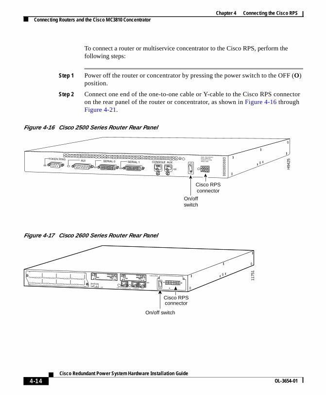
To connect a router or multiservice concentrator to the Cisco RPS, perform thefollowing steps:
Step 1 Power off the router or concentrator by pressing the power switch to the OFFO)position.
Step 2 Connect one end of the one-to-one cable or Y-cable to the Cisco RPS conneon the rear panel of the router or concentrator, as shown inFigure 4-16 throughFigure 4-21.
Figure 4-16 Cisco 2500 Series Router Rear Panel
Figure 4-17 Cisco 2600 Series Router Rear Panel
H94
25
TOKEN RING
Cisco RPSconnector
On/off switch
Input: 100-240VACFreq: 50/60 HzCurrent: 1.2-0.6AWatts: 40W
SEE MANUAL BEFORE INSTALLATION
SERIAL 1
SERIAL 0CONN
CONNWIC2A/SSEE MANUAL BEFORE INSTALLATION
SERIAL 1
SERIAL 0CONN
CONNWIC2A/S
Cisco 2611
W0
AUXCONSOLEETHERNET 0 ACTLINKLINK
1175
1
Cisco RPS connector
On/off switch
4-14Cisco Redundant Power System Hardware Installation Guide
OL-3654-01
Chapter 4 Connecting the Cisco RPSConnecting Routers and the Cisco MC3810 Concentrator
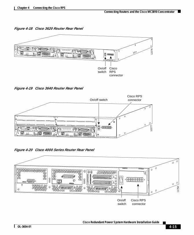
Figure 4-18 Cisco 3620 Router Rear Panel
Figure 4-19 Cisco 3640 Router Rear Panel
Figure 4-20 Cisco 4000 Series Router Rear Panel
2E2W
W1
1 ETHERNET 1
ETH 1
ETHERNET 0
ENAUI
WO
AC
T
LNK
AC
T
LNK
AC
T
SERIAL
BRINT1
B1
B2
NT
1
2E2W W1
ETHERNET 0
AUIEN
AC
T
LNK
AC
T
LNK
DO NOT INSTALL WAN INTERFACECARDS WITH POWER APPLIED
AC
T
SERIAL
SEE MANUAL BEFORE INSTALLATION
1227
6
0ETHERNET 1
CiscoRPSconnector
DC INPUT FOR USE WITH CISCO RPS+5V– – –14A, +12V– – –5A, -12V– – –3A
On/offswitch
1227
7
INPUT 100-240VAC 50/60HZ 3.0-1.5 AMPS
2E2W
W1
ETHERNET 1 ETHERNET 0
ENAUI
WO
AC
T
LNK
AC
T
LNK
AC
T
SERIAL
BRINT1
B1
B2
NT
1
2
3
1
2E2W W1
STP
ETHERNET 0
AUIENA
CT
LNK
AC
T
LNK
DO NOT INSTALL WAN INTERFACECARDS WITH POWER APPLIED A
CT
SERIALSEE MANUAL BEFORE INSTALLATION
ETHERNET 1
Cisco RPSconnectorOn/off switch
1175
0
Cisco RPS connector
On/off switch
4-15Cisco Redundant Power System Hardware Installation Guide
OL-3654-01

Chapter 4 Connecting the Cisco RPSConnecting Routers and the Cisco MC3810 Concentrator
r on
Figure 4-21 Cisco MC3810 Multiservice Concentrator Rear Panel
Step 3 Connect the other end of the one-to-one or Y-cable to the rear panel connectothe Cisco RPS, as shown inFigure 4-22 andFigure 4-23.
Figure 4-22 Connecting a One-to-One Cable for Quasi-Redundant Power
1221
2
Cisco RPS connector
On/off switch
SERIAL 1 CONSOLE AUX
PO
ER
W
AVM
1 2 3 4 5 6
SERIAL 0ETHERNET 0
2909
0
AC INPUT 1100-200 V~ 50/60 Hz
10-5 A 1000 W
AC INPUT 2100-200 V~ 50/60 Hz
10-5 A 1000 W
DC OUTPUT 1 DC OUTPUT 2 DC OUTPUT 3 DC OUTPUT 4
4-16Cisco Redundant Power System Hardware Installation Guide
OL-3654-01

Chapter 4 Connecting the Cisco RPSConnecting Routers and the Cisco MC3810 Concentrator
othbles
Figure 4-23 Connecting a Two-to-One Y-Cable for Fully Redundant Power
Step 4 On the rear panel of the Cisco RPS, connect an AC power cable to either or bof the power connectors. Use the cable locks on the Cisco RPS to lock the cain place. (SeeFigure 4-24.)
Figure 4-24 Connecting the AC Power Cables to the Cisco RPS
2908
9AC INPUT 1100-200 V~ 50/60 Hz
10-5 A 1000 W
AC INPUT 2100-200 V~ 50/60 Hz
10-5 A 1000 W
DC OUTPUT 1 DC OUTPUT 2 DC OUTPUT 3 DC OUTPUT 4
2909
2
Cable locks
4-17Cisco Redundant Power System Hardware Installation Guide
OL-3654-01

Chapter 4 Connecting the Cisco RPSConnecting Routers and the Cisco MC3810 Concentrator
tle is
(
nds.. If
Step 5 Connect the other end of the Cisco RPS AC power cable into a grounded ACpower outlet.
Step 6 Power up the Cisco RPS. There is one power switch for each of the AC inpupower modules. Make sure that the power switch for each connected AC cabin the ON (|) position. (SeeFigure 4-25.)
Figure 4-25 Powering Up the Cisco RPS
Step 7 Power on the router or concentrator by pressing the power switch to the ON|)position.
The Cisco RPS is on and provides power to the external device in 10 to 15 secoThe Cisco RPS is working properly when all its front-panel LEDs are solid greenthe external device does not power up, seeChapter 5, “Troubleshooting theCisco RPS.”
2909
1
Power switch
4-18Cisco Redundant Power System Hardware Installation Guide
OL-3654-01