connecticut society of civil engineers
TRANSCRIPT

1
Connecticut Society of Civil Engineers
Subsurface Sewage Disposal System Design and Updates
May 26, 2011
Presented by:
Connecticut Department of Public HealthEnvironmental Engineering Program410 Capitol Avenue- MS# 51-SEW
P. O. Box 340480Hartford CT, 06134
Phone: (860) 509-7296Fax: (860) 509-7295
Program Updates
Circular letter 2009-62New plan review fees (effective 10/1/09)– Each large system (over 2000 GPD)
• $625
– Each small system• $200
CT DPH approval required for small and large systems on Large System Sites (sites with a large system)
Program Updates
DEP draft General Permit for existing sites regulated by DEP– Tech. Standards to be used for design of small
septic systems.New Program Supervisor for DEP Subsurface Group, Michael Hart (replaces Warren Herzig)860-424-3819– Jennifer Perry left program
CEHA Soils Training Workshop October 2011– Budget $100-150 per person
Download a copy for free.
Available today for $3

2
Regulations
19-13-B100a Building Conversions, Change in use, Additions (effective August 3, 1998
19-13-B103 Discharges 5000 Gallons Per Day or less (effective August 16, 1982)
Technical Standards 2011Latest revision January 1, 2011Code Advisory Committee– COWRA-Bill Hall and Frank Talarico– CEHA- Jeff Polhemus and Don Mitchell– CADH- Rob Miller, Neal Lustig and Rick Matheny– CSCE- Doug DiVesta– Home Builders- George Smilas and Larry Fiano– DEP-Kim Hudak, Mike Hart and Oswald Inglese – Soil Scientist- Rick Zulick and John Ianni– Professional Engineers- Jay Keillor, Larry Marcik,
Roger Nemergut– DPH- Robert Scully, Matt Pawlik, Sean Merrigan
and Amanda Clark
Design ManualSubsurface Sewage Disposal Systems for Households and Small Commercial Buildings. July, 1998
Guidelines- acceptable practices in CT
Scope and Purpose
Guidance for engineers, installers and local health officials in the design and construction of subsurface sewage disposal systems for households and small business.Design considerations and practical solutions for overcoming specific installation problems.
Website Information www.ct.gov/dph/subsurfacesewageTraining Section (bottom of page) Operation and MaintenanceRegulations and Technical StandardsDesign ManualCircular LettersNew product approvals Code Advisory Committee
What is Sewage?
Domestic Sewage

3
Domestic Sewage
Domestic SewageWater or human excretions incidental to the occupancy of a residential building or non-residential buildingWaste from restaurants and commercial buildingsToilet wastes, laundry wastes, kitchen wastes (garbage grinders)
Domestic Sewage
Does NOT include process water, cooling water, water softener discharge (DEP), cellar or floor drains, surface water from roofs or yard drains, swimming pool backwash, etc.Wastes requiring permits from DEP:dry cleaning, car washes, oils, slaughter house, photographic processing liquids, furniture stripping
How we dispose sewage?
Where does it go?
Methods of Sewage Disposal
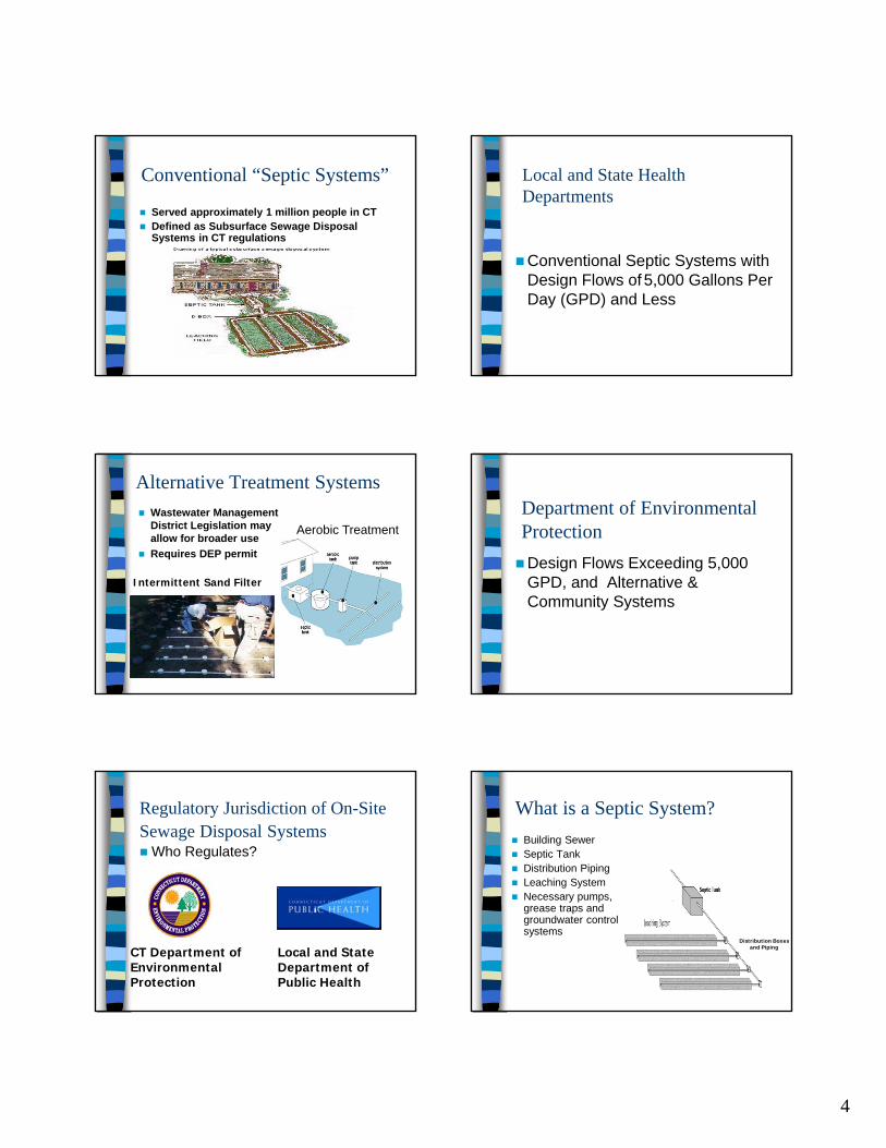
Public SewersConventional “Septic Systems”Alternative Treatment Systems
Public Sewers
Serves approximately 70 percent of the CT population Predominantly in urban areas and area of high density development
4
Conventional “Septic Systems”
Served approximately 1 million people in CTDefined as Subsurface Sewage Disposal Systems in CT regulations
Alternative Treatment SystemsWastewater Management District Legislation may allow for broader useRequires DEP permit
Intermittent Sand Filter
Aerobic Treatment
Regulatory Jurisdiction of On-Site Sewage Disposal Systems
Who Regulates?
CT Department of Environmental Protection
Local and State Department of Public Health
Local and State Health Departments
Conventional Septic Systems with Design Flows of5,000 Gallons Per Day (GPD) and Less
Department of Environmental ProtectionDesign Flows Exceeding 5,000 GPD, and Alternative & Community Systems
What is a Septic System?Building SewerSeptic TankDistribution PipingLeaching SystemNecessary pumps, grease traps and groundwater control systems
Distribution Boxesand Piping

5
Leaching SystemSeptic Tank
Soil
Groundwater
Sewer Line
Building or House Sewer
Refers to the pipe located between the building served connecting to the septic tank
Septic Tank
Provides the primary treatment: separates, settles and digests
Septic Tank
<-Inlet BaffleOutletFilter ->
2/3Capacity 1/3
Capacity
Access Ports
Solids
Liquid
Grease
Concrete Septic Tank

6
Concrete Septic Tanks
All SSDS must have a septic tankTanks and risers under traffic areas must be rated for H-20 wheel loadingMust not be shipped prior to 14 days without support documentationConform to ASTM C 1227 with exceptions. Watertight tank seals required when specified.
Septic Tank
Septic Tank with Effluent Filter
Plastic Septic Tank
Non-Concrete Septic Tanks
Must be installed per manufacturers specifications.Tank bottoms located in groundwater must have anti-buoyancy / flotation provisionsAppendix D

7
Section V Septic Tanks
Proprietary leaching system companies should be consulted if a repair plan includes a single compartment septic tank. Septic tanks shall have a minimum of 6 inches of cover.Watertight tank seal required if specified
by plan designer.
Sizing Septic Tanks (pg. 29)
Minimum size septic tank is 1,000 gallonsSizing septic tanks for residential buildings are based on bedrooms– 3 or fewer bedrooms 1,000 gallon tank
Sizing Septic Tanks (pg. 30)
– Garbage grinder add 250 gallons (Note: not recommended)
– Large tub 100 gallons add 250 gallons to septic tank size
– Large tub over 200 gallons add 500 gallons to septic tank size.
Sizing Septic Tanks for Residential Buildings5 bedroom single family house– 1250 gallons for four bedrooms– Add 125 for each bedroom after 4
1250 (first 4)+125 (each bedroom after 4)1375 minimum gallons

8
Sizing Septic Tanks for Residential Buildings
Calculations– 24 Bedroom apartment building
– 1250 for the first 4 bedrooms
1,250 (first 4 bedrooms)+5,000 (20 bedrooms times 250 for multi-family) 6,250 gallons
Sizing Septic Tanks for Non-residential Buildings and Residential InstitutionsMinimum capacity equal to the 24 hour design flow, but not less then 1000 gallons.– Restaurants without grease removal, the
septic tank must increase capacity by 50%– If high peak flow conditions exist a 2 hour
minimum detention time must be used for sizing septic tank
Sizing Septic Tanks for Non-residential Buildings and Residential InstitutionsHigh Peak Flow Conditions– Theater: Monday-Friday 200GPD
Saturday-Sunday 2000GPD• Peak intermission Flow=500 Gallons/30 minute
500 Gallons = X Gallons0.5 hrs 2 hrs
X = 2,000 gallons
Cleaning Effluent Filter
Distribution Piping
Consists of the piping leading from the septic tank to the leaching system.
Distribution Piping

9
Distribution Box
Perforated Piping
Perforated Piping
Distribution Piping Being Installed
Distribution Box Installed
Distribution Box Installed

10
Leaching System
Properly functioning leaching system should disperse effluent (liquid from the septic tank) into the surrounding soils without breaking out on the ground surface or polluting the groundwater.
Leaching Systems
Leaching System bottom not to be installed more than 8’ into finished grade. <8’
Max width of a leaching product is 6.5’
Leaching Systems
– Leaching systems under vehicular travel areas require 1 foot minimum cover over stone trenches, precast concrete structures shall be H-20 load rated, and proprietary systems shall only be installed in vehicular travel areas if authorized by the manufacturer, and require proprietary companies to provide DPH dated supporting documentation.
Leaching Systems
For suitability purposes, the leaching system area includes the soil within 10 feetin all directions of the leaching system.
Leaching System:Reserve Area
Reserve areas are not required to meet MLSS, however, where feasible reserve areas should provide additional spread.
Leaching System:Reserve Area
Select fill placement in reserve area no longer required in the event fill is placed in the reserve area as part of primary system construction. Require reserve area preparation for multi-family and commercial buildings located under paved asphalt or poured concrete vehicular travel areas only.
11
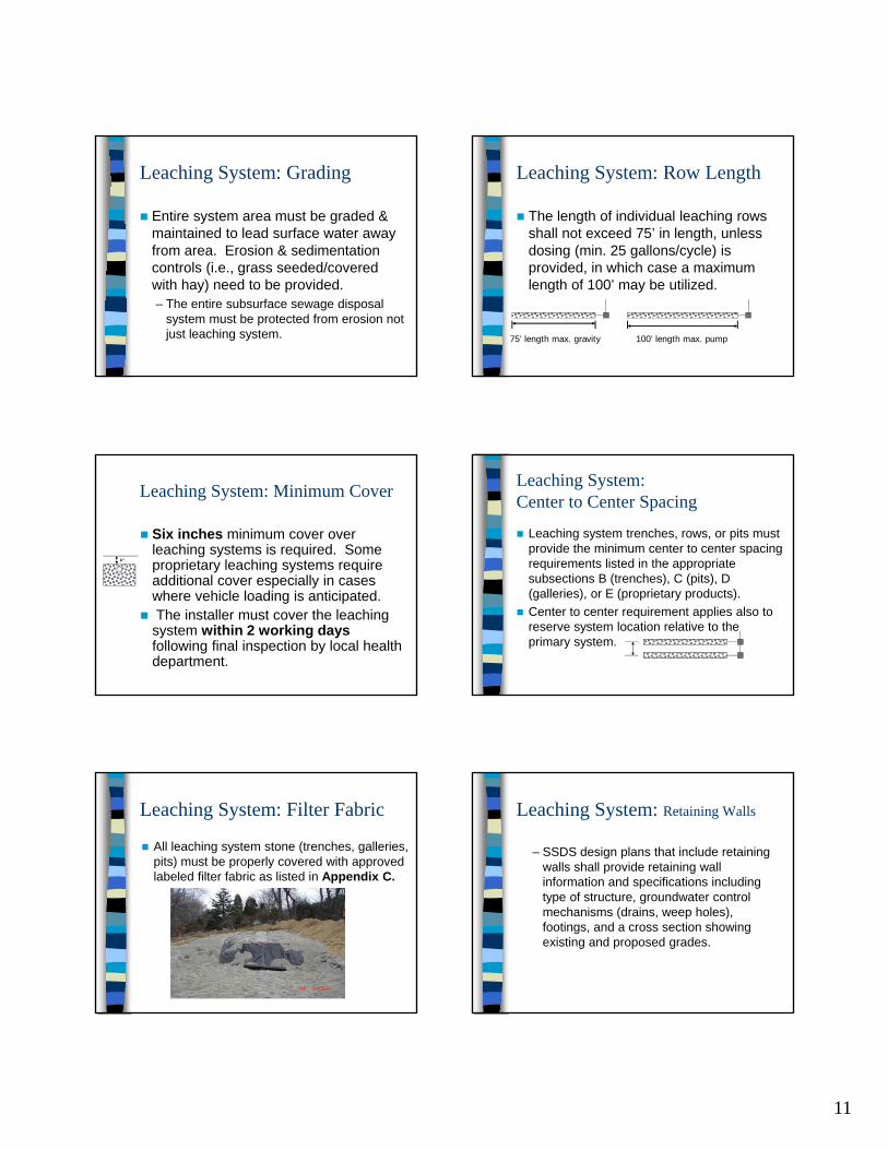
Leaching System: Grading
Entire system area must be graded & maintained to lead surface water away from area. Erosion & sedimentation controls (i.e., grass seeded/covered with hay) need to be provided.– The entire subsurface sewage disposal
system must be protected from erosion not just leaching system.
Leaching System: Minimum Cover
Six inches minimum cover over leaching systems is required. Some proprietary leaching systems require additional cover especially in cases where vehicle loading is anticipated. The installer must cover the leaching
system within 2 working daysfollowing final inspection by local health department.
6”
Leaching System: Filter Fabric
All leaching system stone (trenches, galleries, pits) must be properly covered with approved labeled filter fabric as listed in Appendix C.
Leaching System: Row Length
The length of individual leaching rows shall not exceed 75’ in length, unless dosing (min. 25 gallons/cycle) is provided, in which case a maximum length of 100’ may be utilized.
100’ length max. pump75’ length max. gravity
Leaching System: Center to Center Spacing
Leaching system trenches, rows, or pits must provide the minimum center to center spacing requirements listed in the appropriate subsections B (trenches), C (pits), D (galleries), or E (proprietary products). Center to center requirement applies also to reserve system location relative to the primary system.
Leaching System: Retaining Walls
– SSDS design plans that include retaining walls shall provide retaining wall information and specifications including type of structure, groundwater control mechanisms (drains, weep holes), footings, and a cross section showing existing and proposed grades.

12
Leaching System: Center to Center SpacingIf two different types of leaching systems are utilized side by side, the average c-to-c spacing shall be maintained. Example: 12” x 48” stone trenches next to 4’ x 4’ galleries= 10’ c-to-c required (Average of 8 and 12).
10’
10’
Stone Trenches
Acceptable stone meeting gradation specifications
Unacceptable stone

13
Leaching Pit
Galleries – 12-inch high
Galleries - 27-inch Teepees
Galleries – 4’ x 4’
Leaching Systems (pg. 44)
• Proprietary systems: Several companies require use of a washed sand/C 33 sand. Standards for ASTM C 33 sand and DOT Form 816 fine aggregate (washed sand) referenced.
• Proprietary leaching systems filled or bedded on sand must utilize sand meeting select fill requirements and additional specification per the manufacturer.
Proprietary systems

14
Plastic Chambers
Cultec
Form Cell: Living Filter
Living Filter

15
Cur-Tech Systems

16
Prepare bed
GeoMat FlatGeomatrix
Roll out mat
GeoMat Flat

17
Lay distribution pipe over system per design
GeoMat Flat
Set form in trenchGeoMat Edge
Place mat into smaller slot in form GeoMat Edge
Fill with sand and compact
GeoMat Edge
Move form ahead
GeoMat Edge
Continue until desired length is met
GeoMat Edge

18
Prepare site
GST Leaching System
Assemble form
GST Leaching System
Place lids on form
GST Leaching System
Put sand in and around form
GST Leaching System
Remove lids from form
GST Leaching System
Place stone
GST Leaching System

19
Pull form
GST Leaching System
Place pipe and level to d-box
GST Leaching System
GST Leaching System

20
S-Box
FinsFabric-wrapped Cuspated Core
Appendix A: MLSS (definitions p. 59)
Leaching System Spread: sloping lots must take into account converging & diverging contoursReceiving Soil and Receiving Soil Depth added; Depth to Restrictive Layer removedRestrictive Layer: impervious soil and redoximorphic added; severely restricted hardpan removed
Appendix A: Use of MLSS (p.60)
Language revised stating that New Systems and Code-complying areas shall provide leaching system spread based on natural occurring soils onlyMLSS, hydraulic analysis or loading test used to demonstrate compliance with PHC Section 19-13-B103e(a)(4)

21
Repairs and Potential Repair Areas that cannot provide leaching system spread based on naturally occurring soil require LHD exceptionAn assessment referred to as a Non-Compliant Repair (NCR) MLSS necessary prior to exception being granted by LHD
Appendix A: Use of MLSS (p.60)
NCR MLSS takes into account hydraulic capacity of existing receiving soils (RS) and fill be included in repair designExisting fill must have perc rate faster than 30 min/inch, and be clean material free of debrisRS measured from bottom of leaching system to RL
Appendix A: Use of MLSS (p.60)
Lots with flat water tables; minimum 6” of RS around perimeter of systemLots with gradient; minimum 12” of RS 25’ down gradientMinimum RS Depth (average) provided shall be 18 inches; max is 60 inchesPerc rate of 10.1-20 min/inch can be used for select fill layers
Appendix A: Use of MLSS (p.60)
Leaching systems shall provide max. possible of NCR MLSS based on RS Depth of 18-22 inchesIf NCR MLSS (18-22”) cannot be met, then addition fill may be consideredIf less than 50% of NCR MLSS met, or minimum RS depths not provided, then PE plan required
Appendix A: Use of MLSS (p.60)
NCR MLSS: Lots with <18” of Natural Occurring Soil
12-inch minimum provided 25 ft down gradient and RS Depth at least 18”Calculate NCR MLSS based on RS Depth of 18.0-22 and provide maximum percent possible (if can’t be met)May provide additional fill material to increase RS Depth & reduce NCR MLSS.Leaching area must provide at least 50% of NCR MLSS using receiving soil, including additional fill material, or PE plan required.
RS Depth is average in leaching area and 25 ft down gradient (24+12)/2= 18”

22
NCR MLSS: Lots with <18” of Natural Occurring Soil; Existing Fill on Site
12-inch minimum provided 25 ft down gradient and RS Depth at least 18”Calculate NCR MLSS based on RS Depth of 18.0-22 and provide maximum percent possible (if can’t be met)May provide additional fill material to increase RS Depth & reduce NCR MLSS.Leaching area must provide at least 50% of NCR MLSS using receiving soil, including additional fill material, or PE plan required.
RS Depth is average in leaching area and 25 ft down gradient (30+24)/2= 27”
NCR MLSS: Lots with 18” or more of Natural Occur Soil, but full MLSS cannot be provided:
NCR MLSS must be determined.Calculate NCR MLSS based on RS Depth and provide maximum percent possible (if can’t be met) May provide additional fill material to increase RS Depth & reduce NCR MLSS.Leaching area must provide at least 50% of NCR MLSS using receiving soil, including additional fill material, or PE plan required.

23
RS Depth is average in leaching area and 25 ft down gradient (32+22)/2= 27”
NCR MLSS shall be equivalent to MLSS for purposes of non-flow increasing building additions.Such additions may now be approved as long as other requirements of PHC Section B100a(c) are met.
Appendix A: Use of MLSS (p.60)
Permitted flow noted on Permit to Discharge shall be based on most limited percentage of ELA or NCR MLSS providedPermit to Discharge shall state that system is non-compliant relative to MLSS, and exception has been granted
Appendix A: Use of MLSS (p.60)