conformance test report for en 301489-1 / -3finecontrol.de/fc30/zertifikate/emc_report_ls-30.pdf ·...
TRANSCRIPT

ELECTRONICS TESTING CENTER, TAIWANFile No.: ET93S-08-210-20 EMC TESTING DEPARTMENT Page:1/27
CONFORMANCE TEST REPORTFOR
EN 301489-1 / -3
Report No.: ET93S-08-210-20
Client: Scientech Electronics Co., Ltd.Product: Alarm Base UnitModel: LS-30Manufacturer/supplier: Scientech Electronics Co., Ltd.
Date test item received: 2004/08/30Date test campaign completed: 2004/10/08Date of issue: 2004/10/15
The test result only corresponds to the tested sample. It is not permitted to copy this report,in part or in full, without the permission of the test laboratory.
Total number of pages of this test report: 27 pagesTotal number of pages of this test photos: 18 pages
Test Engineer Checked By Approved By
Benjamin, Terry Huang, Mark Anderson Tsung-Ching Lin
ELECTRONICS TESTING CENTER, TAIWANNO.8, LANE 29, WEN-MING RD.,LO-SHAN TSUN, KUI-SHAN HSIANG,TAOYUAN HSIEN 333TAIWAN, R.O.C.
TEL: (03) 3276170~4INT: +886-3-3276170~4FAX: (03) 3276188INT: +886-3-3276188

ELECTRONICS TESTING CENTER, TAIWANFile No.: ET93S-08-210-20 EMC TESTING DEPARTMENT Page:2/27
CONTENTS
EMC TEST REPORT…………………………………………………………………………..…..1 CONTENTS.………………………….……………………………………………….…………...2
1. TEST REPORT CERTIFICATION..................................................................................................... 42.GENERAL INFORMATIONS ............................................................................................................ 5
2.1 Description of EUT: .................................................................................................................... 52.2 Related Information of EUT: ...................................................................................................... 52.3 Tested Configuration:.................................................................................................................. 52.4 Deviations Record:...................................................................................................................... 52.5 Modification Record: .................................................................................................................. 5
3. SUMMARY OF TEST RESULTS...................................................................................................... 63.1 Emissions: ................................................................................................................................... 6
3.1.1 Conducted emissions............................................................................................................ 63.1.2 Radiated emissions............................................................................................................... 63.1.3 Harmonics Current Emissions.............................................................................................. 63.1.4 Voltage Fluctuations and Flicker.......................................................................................... 6
3.2 Immunity:.................................................................................................................................... 63.2.1 Immunity criteria:................................................................................................................. 63.2.2 Electrostatic discharge: ....................................................................................................... 83.2.3 Radio frequency electromagnetic field (80~1000MHz and 1400~2000MHz): ................... 83.2.4 Fast transients common mode:............................................................................................. 83.2.5 Surges, common and differential mode: .............................................................................. 83.2.6 RF common mode, 0.15~80MHz: ....................................................................................... 83.2.7 Voltage dips and interruptions:............................................................................................. 8
4. TEST DATA & RELATED INFORMATIONS .................................................................................. 94.1 Emissions: ................................................................................................................................... 9
4.1.1 Conducted emissions test: .................................................................................................... 94.1.1.1 Conducted emissions test data: ................................................................................. 9
4.1.2 Radiated emissions test: ..................................................................................................... 154.1.2.1 Radiated emissions test data: .................................................................................. 15
4.1.3 Harmonics Current Emissions Test:................................................................................... 174.1.3.1 Harmonics Current Emissions Test Data: ............................................................... 17
4.1.4 Voltage Fluctuations and Flicker Test: ............................................................................... 194.1.4.1 Voltage Fluctuations and Flicker Test Data: ........................................................... 19
4.2 Immunity:.................................................................................................................................. 204.2.1 Electrostatic discharge: ...................................................................................................... 20
4.2.1.1 Electrostatic discharge test data: ............................................................................. 20

ELECTRONICS TESTING CENTER, TAIWANFile No.: ET93S-08-210-20 EMC TESTING DEPARTMENT Page:3/27
4.2.2 Radio frequency electromagnetic field (80~1000MHz and 1400~2000MHz): ................. 224.2.2.1 Radio frequency electromagnetic field test data: .................................................... 22
4.2.3 Fast transients common mode:........................................................................................... 234.2.3.1 Fast transients common mode test data:.................................................................. 23
4.2.4 Surge, common and differential mode: .............................................................................. 244.2.4.1 Surge, common and differential mode test data:..................................................... 24
4.2.5 RF common mode, 0.15MHz~80MHz: ............................................................................. 254.2.5.1 RF common mode, 0.15MHz~80MHz test data: .................................................... 25
4.2.6 Voltage Interruptions and Voltage Dips Immunity Test: .................................................... 264.2.6.1 Voltage Interruptions and Voltage Dips Immunity Test Data: ................................ 26
5. EQUIPMENTS LIST FOR TESTING.............................................................................................. 27ANNEX A: PHOTOS .......................................................................................................................... A1

ELECTRONICS TESTING CENTER, TAIWANFile No.: ET93S-08-210-20 EMC TESTING DEPARTMENT Page:4/27
1. TEST REPORT CERTIFICATION
Client : Scientech Electronics Co., Ltd.Address : 4F, No. 501-17, Chung-Cheng Rd., Hsin-Tien City, Taipei 231, Taiwan, R.O.C.Manufacturer : Scientech Electronics Co., Ltd.Address : 4F, No. 501-17, Chung-Cheng Rd., Hsin-Tien City, Taipei 231, Taiwan, R.O.C.EUT : Alarm Base Unit
Trade name : LifeSOS
Model No. : LS-30
Test standard : Emissions
301489-1 V1.3.1EN 55022:1998/A1:2000/A2:2003 (Class B)EN 61000-3-2:2000EN 61000-3-3:1995/A1:2001
Immunity
301489-3 V1.4.1EN 61000-4-2:1995/A1:1998/A2:2001EN 61000-4-3:2002/A1:2002EN 61000-4-4:1995/A1:2001/A2:2001EN 61000-4-5:1995/A1:2001EN 61000-4-6:1996/A1:2001EN 61000-4-11:1994/A1:2001
The testing described in this report has been carried out to the best of our knowledge and ability, and our
responsibility is limited to the exercise of reasonable care. This certification is not intended to believe the
sellers from their legal and/or contractual obligations.
Laboratory Introduction: Electronics Testing Center, Taiwan is recognized, filed and mutual recognition
arrangement as following:
ISO9001: TüV Product Service
ISO/IEC 17025: BSMI, CNLA, DGT, NVLAP, CCIBLAC, UL, Compliance
Filing: FCC, Industry Canada, VCCI
MRA: Australia, Hong Kong, New Zealand, Singapore, USA, Japan, Korea, China, APLAC through CNLA

ELECTRONICS TESTING CENTER, TAIWANFile No.: ET93S-08-210-20 EMC TESTING DEPARTMENT Page:5/27
2.GENERAL INFORMATIONS
2.1 Description of EUT:
LS-30 is Alarm Base Unit, it receives radio signal from sensors/transmitters, and controls dialerand siren when it is activated.
2.2 Related Information of EUT:
Power Supply :Adaptor: (T41-12-300C-3)Input: 230Vac, 50Hz, 41mAOutput: DC 12Vdc, 300mA
Power Line : Nonshielded Shielded None , length: 1.8 mSignal Line : Nonshielded Shielded None , length: mControl Line : Nonshielded Shielded None , length: m∗ For more detailed features, please refer to User’s Manual.
2.3 Tested Configuration:
Product Manufacturer Model No. Serial No. I/O CableTelephone Romeo TE-506 ---- 1.8m, Unshielded Line
2.4 Deviations Record:
(If any deviation from additions to or exclusions from test method must be stated) N/A
2.5 Modification Record:
The EUT was modified with coil. (EROCORE / FH0500B)

ELECTRONICS TESTING CENTER, TAIWANFile No.: ET93S-08-210-20 EMC TESTING DEPARTMENT Page:6/27
3. SUMMARY OF TEST RESULTS
3.1 Emissions:3.1.1 Conducted emissions -PASS
Peak EMI Value to the limit: -22.8 dB at 0.236 MHz
3.1.2 Radiated emissions -PASS
Peak EMI Value to the limit: -5.9 dB at 106.630 MHz
3.1.3 Harmonics Current Emissions -PASS
The harmonics current values were under the limits of the class A equipment of theEN 61000-3-2.
3.1.4 Voltage Fluctuations and Flicker -PASS
The voltage fluctuations and flicker values were under the limits of theEN 61000-3-3 requirements.
3.2 Immunity:3.2.1 Immunity criteria:
The results of all of the immunity tests performed on the EUT were evaluated according to thefollowing criteria, and according to the manufacturer’s specifications for the EUT: Performance criterion for continuous phenomena applied to transmitters and receivers:
If no further details are given in the relevant part of the present document dealing with the particular type ofradio equipment, the following general performance criteria for continuous phenomena shall apply.During and after the test, the apparatus shall continue to operate as intended. No degradation of performanceor loss of function is allowed below a permissible performance level specified by the manufacturer when theapparatus is used as intended. In some cased this permissible performance level may be replaced by a permissibleloss of performance.During the test the EUT shall not unintentionally transmit or change its actual operating state and stored data.If the minimum performance level or the permissible performance loss is not specified by the manufacturer, theneither of these may be deduced from the product description and documentation and what the user mayreasonably expect from the apparatus if used as intended.
Performance criterion for equipment which does not provide a continuous communication link:
If no further details are given in the relevant part of the present document dealing with the particular type of radioequipment, the following general performance criteria for transient phenomena shall apply.After the test, the apparatus shall continue to operate as intended. No degradation of performance or loss offunction is allowed below a permissible performance level specified by the manufacturer, when the apparatus isused as intended. In some cases this permissible performance level may be replaced by a permissible loss ofperformance.
Performance criterion for criteria for equipment which does not provide a continuous communication link:
For radio equipment which does not provide a continuous communication link, the performance criteria describedin the subclauses above are not appropriate, then the manufacturer shall declare, for inclusion in the test report,his own specification for an acceptable level of performance or degradation of performance during and/or after

ELECTRONICS TESTING CENTER, TAIWANFile No.: ET93S-08-210-20 EMC TESTING DEPARTMENT Page:7/27
the immunity tests. The performance specification shall be included in the product description anddocumentation.The performance criteria specified by the manufacturer shall give the same degree of immunity protection ascalled for in the foregoing subclauses.
Performance criterion for ancillary equipment tested on a stand alone basis:
If ancillary equipment is intended to be tested on a stand alone basis, the performance criteria described in thesubclauses above are not appropriate, then the manufacturer shall declare, for inclusion in the test report, his ownspecification for an acceptable level of performance or degradation of performance during and/ or after theimmunity tests. The performance specification shall be included in the product description and documentation.The performance criteria specified by the manufacturer shall give the same degree of immunity protection ascalled for in the foregoing subclauses.
Performance criterion CT: If the equipment is of type I or II including ancillary equipment tested on astand lone basis, the performance criteria A of the applicable class as given insubclause 6.3 shall apply. For equipment of type II or type III that requires acommunication link that is maintained during the test, it shall be verified byappropriate means supplied by the manufacturer that the communication link ismaintained during each individual exposure in the test sequence. Where theEUT is a transmitter, tests shall be repeated with the EUT in standby mode toensure that unintentional transmission does not occur.
Performance criterion TT: If the equipment is of the type I or II, including ancillary equipment tested on astand alone basis, the performance criteria B of the applicable class as given insubclause 6.3 shall apply, except for power interruptions exceeding a certaintime the performance criteria deviations are specified in subcluase 7.2.2. Forequipment of the type II or type III that requires a communication link that ismaintained during the test, this shall be verified by appropriate means suppliedby the manufacturer during each individual exposure in the test sequence.Where the EUT is a transmitter, tests shall be repeated with the EUT instandby mode to ensure that unintentional transmission does not occur.
Performance criterion CR: If the equipment is of the type I or II, including ancillary equipment tested on astand alone basis, the performance criteria A of the applicable class as given insubclause 6.3 shall apply. For equipment of the type II of III that requires acommunication link that is maintained during the test, shall be verified byappropriate means supplied by the means supplied by the manufacturer that thecommunication link maintained during each individual exposure in the testsequence. Where the EUT is a transceiver, under no circumstances shall thetransmitter operate unintentionally during the test.
Performance criterion TR: If the equipment is of the type I of II, including ancillary equipment tested on astand alone basis, the performance criteria B of the applicable class as given insubclause 6.3 shall apply, except for power interruptions exceeding a certaintime the performance criteria deviations are specified in subclause 7.2.2. Forequipment of the type II or type III that requires communication link that ismaintained during the test, this shall be verified by appropriate means suppliedby the manufacturer during each individual exposure in the test sequence.Where the EUT is a transceiver, under no circumstances shall the transmitteroperate intentionally during the test.

ELECTRONICS TESTING CENTER, TAIWANFile No.: ET93S-08-210-20 EMC TESTING DEPARTMENT Page:8/27
3.2.2 Electrostatic discharge: -PASSFor transmitters the performance criteria for transient phenomena for transmitter shall apply.For receivers the performance criteria for transient phenomena for receivers shall apply. Forancillary equipment the pass/ failure criteria supplied by the manufacturer shall apply,unless the ancillary equipment is tested in connection with a receiver or transmitter in whichcase the corresponding performance criteria above shall apply.
3.2.3 Radio frequency electromagnetic field (80~1000MHz and 1400~2000MHz): - PASSFor transmitters the performance criteria for continuous phenomena for transmitters shallapply. For receivers the performance criteria for continuous phenomena for receivers shallapply. For ancillary equipment the pass/ failure criteria supplied by the manufacturer shallapply, unless the ancillary equipment is tested in connection with a receiver or transmitter inwhich case the corresponding performance criteria above shall apply.
3.2.4 Fast transients common mode: - PASSFor transceivers the general performance criteria TT shall apply. For stand alone receiversthe general performance criteria TR shall apply. For ancillary equipment the pass/failcriteria supplied by the manufacturer shall apply, unless the ancillary equipment is tested inconnection with receivers or transceivers in which case the corresponding performancecriteria above shall apply.
3.2.5 Surges, common and differential mode: - PASSFor transceivers the general performance criteria TT shall apply. For receivers the generalperformance criteria TR shall apply. For ancillary equipment the pass/fail criteria suppliedby the manufacturer shall apply, unless the ancillary equipment is tested in connection withreceivers or transceivers in which case the corresponding performance criteria above shallapply.
3.2.6 RF common mode, 0.15~80MHz: - PASSFor transceivers the general performance criteria CT shall apply. For stand alone receiversthe general performance criteria CR shall apply. For ancillary equipment the pass/failcriteria supplied by the manufacturer shall apply, unless the ancillary equipment is tested inconnection with receivers or transceivers in which case the corresponding performancecriteria above shall apply.
3.2.7 Voltage dips and interruptions: - PASSFor transceivers the general performance criteria CT shall apply. For stand alone receiversthe general performance criteria CR shall apply. For ancillary equipment the pass/failcriteria supplied by the manufacturer shall apply, unless the ancillary equipment is tested inconnection with receivers or transceivers in which case the corresponding performancecriteria above shall apply.
ELECTRONICS TESTING CENTER, TAIWANFile No.: ET93S-08-210-20 EMC TESTING DEPARTMENT Page:9/27
4. TEST DATA & RELATED INFORMATIONS
4.1 Emissions:4.1.1 Conducted emissions test:
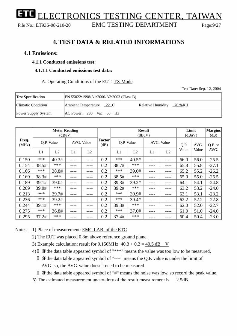
4.1.1.1 Conducted emissions test data:
A. Operating Conditions of the EUT: TX ModeTest Date: Sep. 12, 2004
Test Specification EN 55022:1998/A1:2000/A2:2003 (Class B)
Climatic Condition Ambient Temperature: 22。C Relative Humidity: 70 %RH
Power Supply System AC Power: 230 Vac 50 Hz
Meter Reading(dBuV)
Result(dBuV)
Limit(dBuV)
Margins(dB)
Q.P. Value AVG. Value Q.P. Value AVG. ValueFreq.(MHz)
L1 L2 L1 L2
Factor(dB)
L1 L2 L1 L2
Q.P.Value
AVG.Value
Q.P. orAVG.
0.150 *** 40.3# ---- ---- 0.2 *** 40.5# ---- ---- 66.0 56.0 -25.50.154 38.5# *** ---- ---- 0.2 38.7# *** ---- ---- 65.8 55.8 -27.10.166 *** 38.8# ---- ---- 0.2 *** 39.0# ---- ---- 65.2 55.2 -26.20.169 38.3# *** ---- ---- 0.2 38.5# *** ---- ---- 65.0 55.0 -26.50.189 39.1# 39.0# ---- ---- 0.2 39.3# 39.2# ---- ---- 64.1 54.1 -24.80.209 39.0# *** ---- ---- 0.2 39.2# *** ---- ---- 63.2 53.2 -24.00.213 *** 39.7# ---- ---- 0.2 *** 39.9# ---- ---- 63.1 53.1 -23.20.236 *** 39.2# ---- ---- 0.2 *** 39.4# ---- ---- 62.2 52.2 -22.80.244 39.1# *** ---- ---- 0.2 39.3# *** ---- ---- 62.0 52.0 -22.70.275 *** 36.8# ---- ---- 0.2 *** 37.0# ---- ---- 61.0 51.0 -24.00.295 37.2# *** ---- ---- 0.2 37.4# *** ---- ---- 60.4 50.4 -23.0
Notes: 1) Place of measurement: EMC LAB. of the ETC2) The EUT was placed 0.8m above reference ground plane.3) Example calculation: result for 0.150MHz: 40.3 + 0.2 = 40.5 dBμV4) If the data table appeared symbol of "***" means the value was too low to be measured.
If the data table appeared symbol of "----" means the Q.P. value is under the limit of AVG. so, the AVG.value doesn't need to be measured. If the data table appeared symbol of “#“ means the noise was low, so record the peak value.
5) The estimated measurement uncertainty of the result measurement is ± 2.5dB.

ELECTRONICS TESTING CENTER, TAIWANFile No.: ET93S-08-210-20 EMC TESTING DEPARTMENT Page:10/27

ELECTRONICS TESTING CENTER, TAIWANFile No.: ET93S-08-210-20 EMC TESTING DEPARTMENT Page:11/27

ELECTRONICS TESTING CENTER, TAIWANFile No.: ET93S-08-210-20 EMC TESTING DEPARTMENT Page:12/27
B. Operating Conditions of the EUT: RX ModeTest Date: Sep. 12, 2004
Test Specification EN 55022:1998/A1:2000/A2:2003 (Class B)
Climatic Condition Ambient Temperature: 22。C Relative Humidity: 70 %RH
Power Supply System AC Power: 230 Vac 50 Hz
Meter Reading(dBuV)
Result(dBuV)
Limit(dBuV)
Margins(dB)
Q.P. Value AVG. Value Q.P. Value AVG. ValueFreq.(MHz)
L1 L2 L1 L2
Factor(dB)
L1 L2 L1 L2
Q.P.Value
AVG.Value
Q.P. orAVG.
0.150 39.5# *** ---- ---- 0.2 39.7# *** ---- ---- 65.8 55.8 -26.10.162 *** 37.1# ---- ---- 0.2 *** 37.3# ---- ---- 65.4 55.4 -28.10.166 39.2# *** ---- ---- 0.2 39.4# *** ---- ---- 65.2 55.2 -25.80.173 *** 37.7# ---- ---- 0.2 *** 37.9# ---- ---- 64.8 54.8 -26.90.197 39.3# 38.4# ---- ---- 0.2 39.5# 38.6# ---- ---- 63.7 53.7 -24.20.216 *** 39.3# ---- ---- 0.2 *** 39.5# ---- ---- 63.0 53.0 -23.50.232 39.4# *** ---- ---- 0.2 39.6# *** ---- ---- 62.4 52.4 -22.80.236 *** 39.1# ---- ---- 0.2 *** 39.3# ---- ---- 62.2 52.2 -22.90.271 37.4# *** ---- ---- 0.2 37.6# *** ---- ---- 61.1 51.1 -23.50.279 *** 37.0# ---- ---- 0.2 *** 37.2# ---- ---- 60.8 50.8 -23.60.295 36.8# *** ---- ---- 0.2 37.0# *** ---- ---- 60.4 50.4 -23.4
Notes: 1) Place of measurement: EMC LAB. of the ETC2) The EUT was placed 0.8m above reference ground plane.3) Example calculation: result for 0.150MHz: 39.5 + 0.2 = 39.7 dBμV4) If the data table appeared symbol of "***" means the value was too low to be measured.
If the data table appeared symbol of "----" means the Q.P. value is under the limit of AVG. so, the AVG.value doesn't need to be measured. If the data table appeared symbol of “#“ means the noise was low, so record the peak value.

ELECTRONICS TESTING CENTER, TAIWANFile No.: ET93S-08-210-20 EMC TESTING DEPARTMENT Page:13/27

ELECTRONICS TESTING CENTER, TAIWANFile No.: ET93S-08-210-20 EMC TESTING DEPARTMENT Page:14/27

ELECTRONICS TESTING CENTER, TAIWANFile No.: ET93S-08-210-20 EMC TESTING DEPARTMENT Page:15/27
4.1.2 Radiated emissions test:
4.1.2.1 Radiated emissions test data:
A. Operation Conditions of the EUT: TX ModeTest Date: Sep. 13, 2004
Test Specification EN 55022:1998/A1:2000/A2:2003 (Class B)
Climatic Condition Ambient Temperature: 23。C Relative Humidity: 69%RH
Power Supply System AC Power: 230 Vac 50 Hz
Meter Reading(dBuV)
Results(dBuV/m)
EmissionFrequency
(MHz) HOR. VERT.
CORR'dFactor(dB/m) HOR. VERT.
Limit(dBuV/m)
Margins(dB)
31.940 *** *** 19.1 *** *** 30.0 ***72.680 *** 7.0 8.5 *** 15.5 30.0 -14.5106.630 14.1 *** 10.0 24.1 *** 30.0 -5.9126.030 *** 13.6 9.8 *** 23.4 30.0 -6.6130.880 13.6 *** 9.8 23.4 *** 30.0 -6.6148.340 *** 8.4 11.7 *** 20.1 30.0 -9.9158.040 *** 8.5 11.4 *** 19.9 30.0 -10.1218.180 2.0 *** 14.7 16.7 *** 30.0 -13.3218.180 *** 2.6 14.7 *** 17.3 30.0 -12.7261.830 3.5 *** 17.1 20.6 *** 37.0 -16.4293.840 1.7 *** 18.1 19.8 *** 37.0 -17.2390.840 9.1 *** 21.1 30.2 *** 37.0 -6.8
Notes: 1) Place of Measurement: Measuring site of the ETC2) Measurement Distance: 10 m3) Height of table on which the EUT was placed: 0.8 m4) Height of Receiving Antenna: 1 - 4 m5) Example Calculation : result for 72.680 MHz: 7.0+ (8.5) = 15.5 dBμV/m6) If the data table appeared symbol of "***" means the value was too low to be measured.
If the data table appeared symbol of “#“ means the noise was low, so record the peak value.7) The estimated measurement uncertainty of the result measurement is
+ 4.5dB / - 4.6dB (30MHz ≦ ƒ ≦ 300MHz)+ 4.3dB / - 4.3dB (300MHz ≦ ƒ ≦ 1GHz)

ELECTRONICS TESTING CENTER, TAIWANFile No.: ET93S-08-210-20 EMC TESTING DEPARTMENT Page:16/27
B. Operation Conditions of the EUT: RX ModeTest Date: Sep. 13, 2004
Test Specification EN 55022:1998/A1:2000/A2:2003 (Class B)
Climatic Condition Ambient Temperature: 23。C Relative Humidity: 69%RH
Power Supply System AC Power: 230 Vac 50 Hz
Meter Reading(dBuV)
Results(dBuV/m)
EmissionFrequency
(MHz) HOR. VERT.
CORR'dFactor(dB/m) HOR. VERT.
Limit(dBuV/m)
Margins(dB)
85.290 10.4 13.8 9.4 19.8 23.2 30.0 -6.831.940 *** *** 19.1 *** *** 30.0 ***92.080 *** 12.7 9.4 *** 22.1 30.0 -7.9121.180 11.3 *** 9.4 20.7 *** 30.0 -9.3126.030 *** 11.8 9.8 *** 21.6 30.0 -8.4135.730 8.4 *** 11.2 19.6 *** 30.0 -10.4138.640 *** 7.7 11.2 *** 18.9 30.0 -11.1153.190 *** 4.9 11.7 *** 16.6 30.0 -13.4253.130 2.4 *** 16.5 18.9 *** 37.0 -18.1281.230 3.9 *** 17.1 21.0 *** 37.0 -16.0310.330 1.1 *** 18.1 19.2 *** 37.0 -17.8
Notes: 1) Place of Measurement: Measuring site of the ETC2) Measurement Distance: 10 m3) Height of table on which the EUT was placed: 0.8 m4) Height of Receiving Antenna: 1 - 4 m5) Example Calculation : result for 85.290 MHz: 10.4 + (9.4) = 19.8 dBμV/m6) If the data table appeared symbol of "***" means the value was too low to be measured.
If the data table appeared symbol of “#“ means the noise was low, so record the peak value.7) The estimated measurement uncertainty of the result measurement is
+ 4.5dB / - 4.6dB (30MHz ≦ ƒ ≦ 300MHz)+ 4.3dB / - 4.3dB (300MHz ≦ ƒ ≦ 1GHz)

ELECTRONICS TESTING CENTER, TAIWANFile No.: ET93S-08-210-20 EMC TESTING DEPARTMENT Page:17/27
4.1.3 Harmonics Current Emissions Test:
4.1.3.1 Harmonics Current Emissions Test Data:
Operating Conditions of the EUT: Operation ModeTest Date: Oct. 07, 2004
Test Specification EN 61000-3-2:2000
Climatic Condition Ambient Temperature: 24。C Relative Humidity: 56%RH
Power Supply System AC Power: 230 Vac 50 Hz
Test data see the next pages.

ELECTRONICS TESTING CENTER, TAIWANFile No.: ET93S-08-210-20 EMC TESTING DEPARTMENT Page:18/27
ELECTRONICS TESTING CENTER, TAIWANFile No.: ET93S-08-210-20 EMC TESTING DEPARTMENT Page:19/27
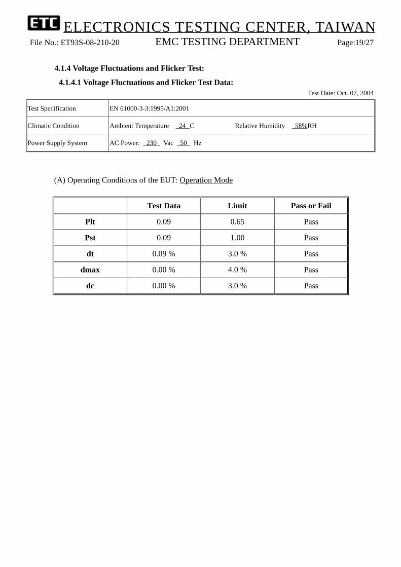
4.1.4 Voltage Fluctuations and Flicker Test:
4.1.4.1 Voltage Fluctuations and Flicker Test Data:Test Date: Oct. 07, 2004
Test Specification EN 61000-3-3:1995/A1:2001
Climatic Condition Ambient Temperature: 24。C Relative Humidity: 58%RH
Power Supply System AC Power: 230 Vac 50 Hz
(A) Operating Conditions of the EUT: Operation Mode
Test Data Limit Pass or Fail
Plt 0.09 0.65 Pass
Pst 0.09 1.00 Pass
dt 0.09 % 3.0 % Pass
dmax 0.00 % 4.0 % Pass
dc 0.00 % 3.0 % Pass

ELECTRONICS TESTING CENTER, TAIWANFile No.: ET93S-08-210-20 EMC TESTING DEPARTMENT Page:20/27
4.2 Immunity:4.2.1 Electrostatic discharge:
4.2.1.1 Electrostatic discharge test data:
Operating Conditions of the EUT: Operation Mode
Test Date: Oct. 08, 2004
Test Specification EN 61000-4-2:1995/A1:1998/A2:2001
Ambient Temperature: 23。C Relative Humidity: 53%RHClimatic Condition
Atmospheric Pressure: 987 mbar
Power Supply System AC Power 230 Vac 50 Hz
Energy-Storage CapacitorDischarge Resistor
: 150 pF: 330 Ω Discharge Times : 10 times/each condition
\ DischargeMode Contact Discharge Air Discharge
\ESD Voltage 2 kV 4 kV kV kV 2 kV 4 kV 8 kV kV
\Points\Result\Polarity + − + − + − + − + − + − + − + −
VCP A A A A -- -- -- -- -- -- -- -- -- -- -- --
HCP A A A A -- -- -- -- -- -- -- -- -- -- -- --
1~9 -- -- -- -- -- -- -- -- A A A A A A -- --
-- -- -- -- -- -- -- -- -- -- -- -- -- -- -- --
Note: “ A ” means the EUT function was correct during the test. “ -- ” means the test could not be carried out.

ELECTRONICS TESTING CENTER, TAIWANFile No.: ET93S-08-210-20 EMC TESTING DEPARTMENT Page:21/27
TEST POINTS
VCP VCP
HCP
1
42 3
VCP VCP
56
7
8
9

ELECTRONICS TESTING CENTER, TAIWANFile No.: ET93S-08-210-20 EMC TESTING DEPARTMENT Page:22/27
4.2.2 Radio frequency electromagnetic field (80~1000MHz and 1400~2000MHz):
4.2.2.1 Radio frequency electromagnetic field test data:
Operating Conditions of the EUT: Operation ModeTest Date: Oct. 05 2004
Test Specification EN 61000-4-3:2002/A1:2002
Climatic Condition Ambient Temperature: 18。C Relative Humidity: 60%RH
Power Supply System AC Power 230 Vac 50 Hz
Frequency Range :80 MHz ~ 1000 MHz 1400 MHz ~ 2000 MHz Field Strength :3 V/m Modulation (AM 1kHz 80%)
Sweep Rate :≤ 1.5×10⁻³ decades/s Step Size :≤ 1 % of preceding frequency value Dwell Time :2.9 s
Frequency Range (MHz) Polarization of Device Test Result
80~1000 Vertical A
80~1000 Horizontal A
1400~2000 Vertical A
1400~2000 Horizontal A
Note : “ A ” means the EUT function was correct during the test .

ELECTRONICS TESTING CENTER, TAIWANFile No.: ET93S-08-210-20 EMC TESTING DEPARTMENT Page:23/27
4.2.3 Fast transients common mode:
4.2.3.1 Fast transients common mode test data:
Operating Conditions of the EUT: Operation Mode
Test Date: Oct. 07, 2004
Test Specification EN 61000-4-4:1995/A1:2001/A2:2001
Ambient Temperature: 24。C Relative Humidity: 56 %RHClimatic Condition
Atmospheric Pressure: 986 mbar
Power Supply System AC Power: 230 Vac 50 Hz
Pulse: 5 /50nsBurst: 15ms /300ms
Repetition Rate: 2.5kHz above 2.0kV5kHz below and equal 2.0kV Test time: 1 min/each condition
1 kV kV\Voltage\Polarity\
\Test Point\Mode\Result\ + - + -
L A A -- --Power Line
N A A -- --
Note: “ A ” means the EUT function was correct during the test. “ -- ” means the test could not be carried out.

ELECTRONICS TESTING CENTER, TAIWANFile No.: ET93S-08-210-20 EMC TESTING DEPARTMENT Page:24/27
4.2.4 Surge, common and differential mode:
4.2.4.1 Surge, common and differential mode test data:
Operating Conditions of the EUT: Operation ModeTest Date: Oct. 07, 2004
Test Specification EN 61000-4-5:1995/A1:2001
Ambient Temperature: 24。C Relative Humidity: 56 %RHClimatic Condition
Atmospheric Pressure: 986 mbar
Power Supply System AC Power: 230 Vac 50 Hz
Waveform: 1.2/50µs(8/20µs) Repetition rate: 60 sec Times: 5 times/each condition
\Phase\Voltage \Mode \Polarity \Result 0。 90。 180。 270。
+ A A A A0.5 kV L − N
− A A A A
Note: “ A ” means the EUT function was correct during the test.

ELECTRONICS TESTING CENTER, TAIWANFile No.: ET93S-08-210-20 EMC TESTING DEPARTMENT Page:25/27
4.2.5 RF common mode, 0.15MHz~80MHz:
4.2.5.1 RF common mode, 0.15MHz~80MHz test data:
Operating Conditions of the EUT: Operation ModeTest Date: Oct. 06, 2004
Test Specification EN 61000-4-6:1996/A1:2001
Climatic Condition Ambient Temperature: 22。C Relative Humidity: 50%RH
Power Supply System AC Power 230 Vac 50 Hz
Frequency Range :0.15 MHz ~ 80 MHz Test Voltage :3 V Modulation (AM 1kHz 80%)
Sweep Rate :≤ 1.5×10⁻³ decades/s Step Size :≤ 1 % of preceding frequency value Dwell Time :2.9 s
Frequency Range (MHz) Tested Line Test Result
0.15~80 Power Line (M2) A
Note : “ A ” means the EUT function was correct during the test .

ELECTRONICS TESTING CENTER, TAIWANFile No.: ET93S-08-210-20 EMC TESTING DEPARTMENT Page:26/27
4.2.6 Voltage Interruptions and Voltage Dips Immunity Test:
4.2.6.1 Voltage Interruptions and Voltage Dips Immunity Test Data:
Operating Conditions of the EUT: Operation ModeTest Date: Oct. 08, 2004
Test Specification EN 61000-4-11:1994/A1:2001
Ambient Temperature: 24。C Relative Humidity: 56%RHClimatic Condition
Atmospheric Pressure: 987 mbar
Power Supply System AC Power: 230 Vac 50 Hz
Test mode Voltage dips Durations(ms) Interval(s) Times Phase Result
Voltage interruptions 100% 5000 10 12 0。/180。 B
60% 100 10 12 0。/180。 AVoltage dips in %UT
30% 10 10 12 0。/180。 A
Note: “ A ” means the EUT function was correct during the test. “ B ” means the EUT function was not correct during the test, which was recovered by itself after test.

ELECTRONICS TESTING CENTER, TAIWANFile No.: ET93S-08-210-20 EMC TESTING DEPARTMENT Page:27/27
5. EQUIPMENTS LIST FOR TESTING
Item Name Manufacturer Model Valid Date
1 EMI Test Receiver R&S ESCS30 Sep. 23, 2005
2 L.I.S.N. EMCO 3825 Oct. 26, 2004
3 EMI Test Receiver HP 8546A Jun. 19, 2005
4 Ant. - LogBicone Schwarzbeck VULB 9160 Sep. 18, 2005
5 Power analyzer XITRON 2503AHF Feb. 22, 2005
6 Power source PACIFIC AMX-Series Mar. 29, 2005
7 Standard impedance XITRON 2520 Oct. 04, 2005
8 ESD simulator KeyTek MZ-15/EC May 15, 2005
9 Metering Unit & Probe EMCO 7122 Oct. 30, 2004
10 RF Generator Agilent 83640B Sep. 23, 2005
11 Amplifier AR 50S1G4AM1 Jun. 01, 2005
12 Amplifier KALMUS 7100LC Oct. 23, 2004
13 EFT/Burst Generator Noiseken FNS-AXIIB50 Oct. 18, 2005
14 Lighting Surge Simulator Noiseken LSS-15AX Sep. 15, 2005
15 Signal Generator MARCONI 2030 Oct. 30, 2004
16 Wideband RF Power Amplifier KALMUS 225LC Aug. 24, 2005
17 RF Voltmeter Boonton 9200B May 28, 2005
18 CDN FCC FCC-801-M2-25 Aug. 22, 2005
19 EM Injection Clamp FCC F-203I-23mm May 10, 2005
20 Mains interference simulator Haefely PLINE 1610 Sep. 15, 2005

ELECTRONICS TESTING CENTER, TAIWANFile No.: ET93S-08-210-20 EMC TESTING DEPARTMENT Page: A1/A18
ANNEX A: PHOTOS1. Conducted Emissions Test Setup Photos

ELECTRONICS TESTING CENTER, TAIWANFile No.: ET93S-08-210-20 EMC TESTING DEPARTMENT Page: A2/A18
2. Radiated Emissions Test Setup Photos
ELECTRONICS TESTING CENTER, TAIWANFile No.: ET93S-08-210-20 EMC TESTING DEPARTMENT Page: A3/A18
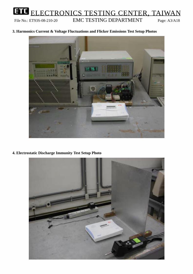
3. Harmonics Current & Voltage Fluctuations and Flicker Emissions Test Setup Photos
4. Electrostatic Discharge Immunity Test Setup Photo

ELECTRONICS TESTING CENTER, TAIWANFile No.: ET93S-08-210-20 EMC TESTING DEPARTMENT Page: A4/A18
5. RF Radiated Fields Test Setup Photo
6. EFT/Burst Immunity Test Setup Photo

ELECTRONICS TESTING CENTER, TAIWANFile No.: ET93S-08-210-20 EMC TESTING DEPARTMENT Page: A5/A18
7. Surge Immunity Test Setup Photo
8. RF Common Mode Immunity Test Setup Photo

ELECTRONICS TESTING CENTER, TAIWANFile No.: ET93S-08-210-20 EMC TESTING DEPARTMENT Page: A6/A18
9. Voltage Interruptions and Voltage Dips Immunity Test Setup Photo

ELECTRONICS TESTING CENTER, TAIWANFile No.: ET93S-08-210-20 EMC TESTING DEPARTMENT Page: A7/A18
10. Outside view 1 of EUT
11. Outside view 2 of EUT

ELECTRONICS TESTING CENTER, TAIWANFile No.: ET93S-08-210-20 EMC TESTING DEPARTMENT Page: A8/A18
12. Inside view 1 of EUT
13. Inside view 2 of EUT
ELECTRONICS TESTING CENTER, TAIWANFile No.: ET93S-08-210-20 EMC TESTING DEPARTMENT Page: A9/A18
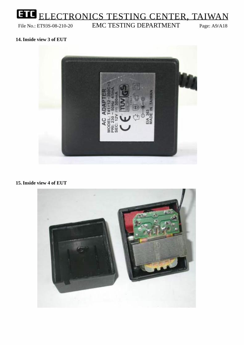
14. Inside view 3 of EUT
15. Inside view 4 of EUT

ELECTRONICS TESTING CENTER, TAIWANFile No.: ET93S-08-210-20 EMC TESTING DEPARTMENT Page: A10/A18
16. Inside view 5 of EUT
17. Inside view 6 of EUT

ELECTRONICS TESTING CENTER, TAIWANFile No.: ET93S-08-210-20 EMC TESTING DEPARTMENT Page: A11/A18
18. Inside view 7 of EUT
19. Inside view 8 of EUT

ELECTRONICS TESTING CENTER, TAIWANFile No.: ET93S-08-210-20 EMC TESTING DEPARTMENT Page: A12/A18
20. Inside view 9 of EUT
21. Inside view 10 of EUT

ELECTRONICS TESTING CENTER, TAIWANFile No.: ET93S-08-210-20 EMC TESTING DEPARTMENT Page: A13/A18
22. Front view of PCB1
23. Rear view of PCB1

ELECTRONICS TESTING CENTER, TAIWANFile No.: ET93S-08-210-20 EMC TESTING DEPARTMENT Page: A14/A18
24. Front view of PCB2
25. Rear view of PCB2

ELECTRONICS TESTING CENTER, TAIWANFile No.: ET93S-08-210-20 EMC TESTING DEPARTMENT Page: A15/A18
26. Front view of PCB3
27. Rear view of PCB3

ELECTRONICS TESTING CENTER, TAIWANFile No.: ET93S-08-210-20 EMC TESTING DEPARTMENT Page: A16/A18
28. Front view of PCB4
29. Rear view of PCB4

ELECTRONICS TESTING CENTER, TAIWANFile No.: ET93S-08-210-20 EMC TESTING DEPARTMENT Page: A17/A18
30. Front view of PCB5
31. Rear view of PCB5

ELECTRONICS TESTING CENTER, TAIWANFile No.: ET93S-08-210-20 EMC TESTING DEPARTMENT Page: A18/A18
32. Front view of PCB6
33. Rear view of PCB6