configuring traffic policies for server load balancing · chapter 3 configuring traffic policies...
TRANSCRIPT

Server Load-Balancing Guide, COL-25328-01
C H A P T E R 3
Configuring Traffic Policies for Server Load BalancingNote The information in this chapter applies to both the ACE module and the ACE appliance unless otherwise noted.
This chapter describes how to configure the ACE to use classification (class) maps and policy maps to filter and match interesting network traffic based on various criteria and load balance the traffic to real servers in server farms using one of the ACE load-balancing predictor methods.
This chapter contains the following major sections:
• Overview of SLB Traffic Policies
• Layer 7 SLB Traffic Policy Configuration Quick Start
• Layer 3 and Layer 4 SLB Traffic Policy Configuration Quick Start
• Configuring HTTP Header Insertion, Deletion, and Rewrite
• Configuring the Compilation Timeout for Regular Expressions
• Configuring a Layer 7 Class Map for Generic TCP and UDP Data Parsing
• Configuring a Layer 7 Class Map for SLB
• Configuring a Layer 7 Policy Map for SLB
• Configuring a Generic Protocol Parameter Map
• Configuring an HTTP Parameter Map
• Configuring an RTSP Parameter Map
3-1isco ACE Application Control Engine
Chapter 3 Configuring Traffic Policies for Server Load BalancingOverview of SLB Traffic Policies
• Configuring a Layer 3 and Layer 4 Class Map for SLB
• Configuring a Layer 3 and Layer 4 Policy Map for SLB
• Applying a Layer 3 and Layer 4 Policy to an Interface
• Configuring NAT for IPv6 to IPv4 Load Balancing
• Configuring NAT for IPv4 to IPv6 Load Balancing
• Configuring UDP Booster
• Configuring the ACE Module to Perform Hashing When the Source and Destination Ports Are Equal
• Configuring RDP Load Balancing
• Configuring RADIUS Load Balancing
• Configuring RTSP Load Balancing
• Configuring SIP Load Balancing
• Example of a Server Load-Balancing Policy Configuration
• Displaying Load-Balancing Configuration Information and Statistics
• Clearing SLB Statistics
• Where to Go Next
Overview of SLB Traffic PoliciesYou classify inbound network traffic destined to, or passing through, the ACE based on a series of flow match criteria specified by a class map. Each class map defines a traffic classification, which is network traffic that is of interest to you. A policy map defines a series of actions (functions) that you want applied to a set of classified inbound traffic.
ACE traffic policies support the following server load-balancing (SLB) traffic attributes:
• Layer 3 and Layer 4 connection information—Source or destination IP address, source or destination port, virtual IP address, and IP protocol
• Layer 7 protocol information—Hypertext Transfer Protocol (HTTP) cookie, HTTP URL, HTTP header, Remote Authentication Dial-In User Service (RADIUS), Remote Desktop Protocol (RDP), Real-Time Streaming Protocol (RTSP), Session Initiation Protocol (SIP), and Secure Sockets Layer (SSL)
3-2Server Load-Balancing Guide, Cisco ACE Application Control Engine
OL-25328-01

Chapter 3 Configuring Traffic Policies for Server Load BalancingOverview of SLB Traffic Policies
The three steps in the traffic classification process are as follows:
1. Create a class map using the class-map command and the associated match commands, which comprise a set of match criteria related to Layer 3 and Layer 4 traffic classifications or Layer 7 protocol classifications.
2. Create a policy map using the policy-map command, which refers to the class maps and identifies a series of actions to perform based on the traffic match criteria.
3. Activate the policy map by associating it with a specific VLAN interface or globally with all VLAN interfaces using the service-policy command to filter the traffic received by the ACE.
Figure 3-1 provides a basic overview of the process required to build and apply the Layer 3, Layer 4, and Layer 7 policies that the ACE uses for SLB. The figure also shows how you associate the various components of the SLB policy configuration with each other.
3-3Server Load-Balancing Guide, Cisco ACE Application Control Engine
OL-25328-01

Chapter 3 Configuring Traffic Policies for Server Load BalancingOverview of SLB Traffic Policies
Figure 3-1 Server Load-Balancing Configuration Flow Diagram
3
2
1 4
5
153638
L7 class mapassociated withL7 policy map
Layer 7 policy mapassociated withLayer 3 and Layer 4policy map
Parameter mapassociated withL3/L4 policy map
Layer 7 HTTP Parameter Map(config)# parameter-map type http loadbalanceHTTP_PARAMMAP
Defines related advanced Layer 7 parameters for SLB: Case sensitivity URL delimiters Maximum parse length for HTTP headers, URLs, and cookies Response to cookie or URL exceeding max bytes HTTP persistence TCP server reuse
Policy Map (Layer 7)(config)# policy-map type loadbalance first-matchPOLICYMAP_L7
Specifies match criteria (class map) andaction: Class map –Drop –Forward –Insert HTTP –Server farm
–Set IP TOS–SSL proxy client–Sticky server farm
L3/L4 class mapassociated withL3/L4 policy map
Class Map (Layer 3 and Layer 4)(config)# class-map match-any CLASSMAP_L3L4
Defines Layer 3 and Layer 4 match criteria applied toinput traffic: Virtual IP address
Policy Map (Layer 3 and Layer 4)(config)# policy-map multi-matchPOLICYMAP_L3L4
Specifies Layer 3 and Layer 4 class map andLayer 7 policy map applied to input traffic: Class map –Load balance –Parameter map
Layer 3 and Layer 4 policy map appliedglobally to all VLAN interfaces or to aspecific VLAN interface
Global VLAN Application(config)# service-policy inputPOLICYMAP_L3L4
Applies the policy map to allVLANs in the context.
Specific VLAN Application(config)# interface vlan 50(config-if)# service-policy inputPOLICYMAP_L3L4
Applies the policy map to theinput of a specific VLAN. Service policy
6
Class Map (Layer 7)(config)# class-map type http loadbalanceCLASSMAP_L7
Defines Layer 7 SLB match criteria applied toinput traffic: Class map HTTP cookie HTTP header HTTP URL Source IP address
3-4Server Load-Balancing Guide, Cisco ACE Application Control Engine
OL-25328-01

Chapter 3 Configuring Traffic Policies for Server Load BalancingLayer 7 SLB Traffic Policy Configuration Quick Start
Layer 7 SLB Traffic Policy Configuration Quick StartTable 3-1 provides a quick overview of the steps required to configure a Layer 7 HTTP class map and a Layer 7 HTTP policy map. You use a similar procedure to configure Layer 7 class maps and policy maps for other supported protocols. Each step includes the CLI command and a reference to the procedure required to complete the task. For a complete description of each feature and all the options associated with the CLI commands, see the sections following Table 3-1.
Table 3-1 Layer 7 SLB Policy Configuration Quick Start
Task and Command Example
1. If you are operating in multiple contexts, observe the CLI prompt to verify that you are operating in the desired context. If necessary, change to, or directly log in to, the correct context.
host1/Admin# changeto C1host1/C1#
The rest of the examples in this table use the Admin context, unless otherwise specified. For details on creating contexts, see the Administration Guide, Cisco ACE Application Control Engine.
2. Enter configuration mode.
host1/Admin# configEnter configuration commands, one per line. End with CNTL/Zhost1/Admin(config)#
3. Create a Layer 7 class map for SLB. See the “Configuring a Layer 7 Class Map for SLB” section.
host1/Admin(config)# class-map type http loadbalance match-all L7SLBCLASShost1/Admin(config-cmap-http-lb)#
3-5Server Load-Balancing Guide, Cisco ACE Application Control Engine
OL-25328-01

Chapter 3 Configuring Traffic Policies for Server Load BalancingLayer 7 SLB Traffic Policy Configuration Quick Start
4. Configure one or more of the following match criteria for the Layer 7 SLB class map:
• Define HTTP content for load balancing. See the “Defining an HTTP Content Match for Load Balancing” section.
host1/Admin(config-cmap-http-lb)# match http content abc*123 offset 50
• Define a cookie for HTTP load balancing. See the “Defining a Cookie for HTTP Load Balancing” section.
host1/Admin(config-cmap-http-lb)# match http cookie TESTCOOKIE1 cookie-value 123456
• Define an HTTP header for load balancing. See the “Defining an HTTP Header for Load Balancing” section.
host1/Admin(config-cmap-http-lb)# match http header Host header-value .*cisco.com
• Define a URL for HTTP load balancing. See the “Defining a URL for HTTP Load Balancing” section.
host1/Admin(config-cmap-http-lb)# match http url /WHATSNEW/LATEST.*
• Define load balancing decisions based on the specific SSL cipher or cipher strength. See the “Defining an SSL Cipher-Based Encryption Level for HTTP Load Balancing” section.
host1/Admin(config-cmap-http-lb)# match cipher equal-to RSA_WITH_RC4_128_CBC_SHA
• Define a source IPv6 or IPv4 match statement. See the “Defining Source IP Address Match Criteria” section.
• host1/Admin(config-cmap-http-lb)# match source-address 2001:DB8:1::1/64
or
• host1/Admin(config-cmap-http-lb)# match source-address 192.168.11.2 255.255.255.0
•
Table 3-1 Layer 7 SLB Policy Configuration Quick Start (continued)
Task and Command Example
3-6Server Load-Balancing Guide, Cisco ACE Application Control Engine
OL-25328-01

Chapter 3 Configuring Traffic Policies for Server Load BalancingLayer 7 SLB Traffic Policy Configuration Quick Start
5. Use the exit command to reenter configuration mode.
host1/Admin(config-cmap-http-lb)# exithost1/Admin(config)#
6. Create a Layer 7 policy map for SLB. See the “Configuring a Layer 7 Policy Map for SLB” section.
host1/Admin(config)# policy-map type loadbalance first-match L7SLBPOLICYhost1/Admin(config-pmap-lb)#
7. Associate the Layer 7 class map that you created in Step 3 with the Layer 7 policy map that you created in Step 6. See the “Associating a Layer 7 Class Map with a Layer 7 Policy Map” section.
host1/Admin(config-pmap-lb)# class L7SLBCLASShost1/Admin(config-pmap-lb-c)#
Table 3-1 Layer 7 SLB Policy Configuration Quick Start (continued)
Task and Command Example
3-7Server Load-Balancing Guide, Cisco ACE Application Control Engine
OL-25328-01

Chapter 3 Configuring Traffic Policies for Server Load BalancingLayer 7 SLB Traffic Policy Configuration Quick Start
8. Specify one or more of the following policy-map actions that you want the ACE to take when network traffic matches a class map:
• Instruct the ACE to compress packets that match a policy map and to use the deflate or gzip compression method when the client browser supports both compression methods. See the “Compressing Packets” section.
The compress command option appears only when you associate an HTTP-type class map with a policy map.
• Instruct the ACE to discard packets that match a policy map. See the “Discarding Requests” section.
host1/Admin(config-pmap-lb-c)# drop
• Instruct the ACE to forward packets that match a policy map without load balancing them. See the “Forwarding Requests Without Load Balancing” section.
host1/Admin(config-pmap-lb-c)# forward
• Enable HTTP header insertion. See the “Configuring HTTP Header Insertion” section.
host1/Admin(config-pmap-lb-c)# insert-http Host header-value www.cisco.com
• Enable load balancing to a server farm. See the “Enabling Load Balancing to a Server Farm” section.
host1/Admin(config-pmap-lb-c)# serverfarm FARM2 backup FARM3
Table 3-1 Layer 7 SLB Policy Configuration Quick Start (continued)
Task and Command Example
3-8Server Load-Balancing Guide, Cisco ACE Application Control Engine
OL-25328-01

Chapter 3 Configuring Traffic Policies for Server Load BalancingLayer 7 SLB Traffic Policy Configuration Quick Start
• Specify the IP differentiated services code point (DSCP) of packets within the traffic class. See the “Configuring a Sticky Server Farm” section.
host1/Admin(config-pmap-lb-c)# set ip tos 8
• If you are using SSL Initiation (ACE acting as an SSL client), specify an SSL proxy service. See the “Specifying an SSL Proxy Service” section. For more information about SSL, see the SSL Guide, Cisco ACE Application Control Engine.
host1/Admin(config-pmap-lb-c)# ssl-proxy client PROXY_SERVICE1
• To use stickiness (connection persistence), specify a sticky server farm for load balancing. See the “Configuring a Sticky Server Farm” section.host1/Admin(config-pmap-lb-c)# sticky-serverfarm STICKY_GROUP1
9. Before you can use a Layer 7 policy map for load balancing, you must associate it with a Layer 3 and Layer 4 SLB policy map. Create the Layer 3 and Layer 4 class map and policy map, then associate the Layer 7 policy map with the Layer 3 and Layer 4 policy map. Finally, associate the Layer 3 and Layer 4 policy map with an interface. See the following sections:
• Configuring a Layer 3 and Layer 4 Class Map for SLB
• Configuring a Layer 3 and Layer 4 Policy Map for SLB
• Applying a Layer 3 and Layer 4 Policy to an Interface
10. Display your class-map and policy-map configurations and statistics (see the “Displaying Load-Balancing Configuration Information and Statistics” section).
host1/Admin# show running-config class-maphost1/Admin# show running-config policy-map
11. (Optional) Save your configuration changes to flash memory.
host1/Admin# copy running-config startup-config
Table 3-1 Layer 7 SLB Policy Configuration Quick Start (continued)
Task and Command Example
3-9Server Load-Balancing Guide, Cisco ACE Application Control Engine
OL-25328-01

Chapter 3 Configuring Traffic Policies for Server Load BalancingLayer 3 and Layer 4 SLB Traffic Policy Configuration Quick Start
Layer 3 and Layer 4 SLB Traffic Policy Configuration Quick Start
Table 3-2 provides a quick overview of the steps required to configure a Layer 3 and Layer 4 class map and a Layer 3 and Layer 4 policy map. Each step includes the CLI command and a reference to the procedure required to complete the task. For a complete description of each feature and all the options associated with the CLI commands, see the sections following Table 3-2.
Table 3-2 Layer 3 and Layer 4 SLB Policy Configuration Quick Start
Task and Command Example
1. If you are operating in multiple contexts, observe the CLI prompt to verify you are operating in the desired context. Change to, or directly log in to, the correct context if necessary.
host1/Admin# changeto C1host1/C1#
For details on creating contexts, see the Virtualization Guide, Cisco ACE Application Control Engine.
2. Enter configuration mode.
host1/Admin# configEnter configuration commands, one per line. End with CNTL/Zhost1/Admin(config)#
3. Create a Layer 3 and Layer 4 SLB class map. See the “Configuring a Layer 3 and Layer 4 Class Map for SLB” section.
host1/Admin(config)# class-map L4VIPCLASShost1/Admin(config-cmap)#
4. Define an IPv6 or IPv4 virtual IP (VIP) address match statement. See the “Defining VIP Address Match Criteria” section.
host1/Admin(config-cmap)# match virtual-address 2001:DB8:1::1 tcp port eq 80orhost1/Admin(config-cmap)# match virtual-address 192.168.1.10 tcp port eq 80
3-10Server Load-Balancing Guide, Cisco ACE Application Control Engine
OL-25328-01

Chapter 3 Configuring Traffic Policies for Server Load BalancingLayer 3 and Layer 4 SLB Traffic Policy Configuration Quick Start
5. Reenter configuration mode.
host1/Admin(config-cmap)# exithost1/Admin(config)#
6. Create a Layer 3 and Layer 4 policy map. See the “Configuring a Layer 3 and Layer 4 Policy Map for SLB” section.
host1/Admin(config)# policy-map multi-match L4SLBPOLICYhost1/Admin(config-pmap)#
7. Associate the Layer 3 and Layer 4 class map that you created in Step 2 with the policy map you created in Step 4. See the “Associating a Layer 3 and Layer 4 Class Map with a Policy Map” section.
host1/Admin(config-pmap)# class L4VIPCLASShost1/Admin(config-pmap-c)#
Table 3-2 Layer 3 and Layer 4 SLB Policy Configuration Quick Start
(continued)
Task and Command Example
3-11Server Load-Balancing Guide, Cisco ACE Application Control Engine
OL-25328-01

Chapter 3 Configuring Traffic Policies for Server Load BalancingLayer 3 and Layer 4 SLB Traffic Policy Configuration Quick Start
8. Specify one or more of the following policy-map actions that you want the ACE to take when network traffic matches a class map:
• (ACE module only) Enable the ACE module to advertise the IP address of a virtual server as the host route for route health injection (RHI). See the “Enabling Advertising of a Virtual Server IP Address for RHI (ACE Module Only)” section.
host1/Admin(config-pmap-c)# loadbalance vip advertise active
• Enable a VIP to reply to ICMP ECHO requests. For example, if a user sends an ICMP ECHO request to a VIP, this command instructs the VIP to send an ICMP ECHO-REPLY. See the “Enabling a VIP to Reply to ICMP Requests” section.
host1/Admin(config-pmap-c)# loadbalance vip icmp-reply
• Associate a Layer 7 SLB policy map with the Layer 3 and Layer 4 policy map to provide an entry point for Layer 7 classifications. See the “Associating a Layer 7 SLB Policy Map with a Layer 3 and Layer 4 SLB Policy Map” section.
host1/Admin(config-pmap-c)# loadbalance policy L7SLBPOLICY
• Associate a generic, HTTP, or RTSP parameter map with the Layer 3 and Layer 4 policy map to define the parameters for the ACE to use. See the “Associating a Generic, HTTP, or RTSP Parameter Map with a Layer 3 and Layer 4 Policy Map” section.
host1/Admin(config-pmap-c)# appl-parameter http advanced-options HTTP_PARAM_MAP1
• Enable a VIP for SLB operations.
host1/Admin(config-pmap-c)# loadbalance vip inservice
9. Activate a policy map and attach it to an interface. See the “Applying a Layer 3 and Layer 4 Policy to an Interface” section.
host1/Admin(config)# interface VLAN50host1/Admin(config-if)# service-policy input L4SLBPOLICYhost1/Admin(config-if)# Ctrl-z
Table 3-2 Layer 3 and Layer 4 SLB Policy Configuration Quick Start
(continued)
Task and Command Example
3-12Server Load-Balancing Guide, Cisco ACE Application Control Engine
OL-25328-01

Chapter 3 Configuring Traffic Policies for Server Load BalancingConfiguring HTTP Header Insertion, Deletion, and Rewrite
Configuring HTTP Header Insertion, Deletion, and Rewrite
This section describes action lists and how to use them to insert, rewrite, and delete HTTP headers. An action list is a named group of actions that you associate with a Layer 7 HTTP class map in a Layer 7 HTTP policy map. You can create an action list to modify an HTTP header by using the action-list type modify http command in configuration mode. The syntax of this command is as follows:
action-list type modify http name
For the name argument, enter a unique name for the action list as an unquoted text string with a a maximum of 64 alphanumeric characters.
For example, enter:
host1/Admin(config)# action-list type modify http HTTP_MODIFY_ACTLISThost1/Admin(config-actlist-mod)#
To remove the action list from the configuration, enter:
host1/Admin(config)# no action-list type modify http HTTP_MODIFY_ACTLIST
10. Display your class-map and policy-map configurations and statistics (see the “Displaying Load-Balancing Configuration Information and Statistics” section).
host1/Admin# show running-config class-maphost1/Admin# show running-config policy-maphost1/Admin# show service-policy name [detail]
11. (Optional) Save your configuration changes to flash memory.
host1/Admin# copy running-config startup-config
Table 3-2 Layer 3 and Layer 4 SLB Policy Configuration Quick Start
(continued)
Task and Command Example
3-13Server Load-Balancing Guide, Cisco ACE Application Control Engine
OL-25328-01

Chapter 3 Configuring Traffic Policies for Server Load BalancingConfiguring HTTP Header Insertion, Deletion, and Rewrite
Note You can associate a maximum of 1024 instances of the same type of regex with a a Layer 4 policy map. This limit applies to all Layer 7 policy-map types, including generic, HTTP, RADIUS, RDP, RTSP, and SIP. You configure regexes in the following:
• Match statements in Layer 7 class maps
• Inline match statements in Layer 7 policy maps
• Layer 7 hash predictors for server farms
• Layer 7 sticky expressions in sticky groups
• Header insertion and rewrite (including SSL URL rewrite) expressions in Layer 7 action lists
The following sections describe the HTTP actions that you can put in an action list:
• Configuring HTTP Header Insertion
• Configuring HTTP Header Rewrite
• Configuring HTTP Header Deletion
You can also add a description for the action list, as described in the “Defining a Description for an Action List” section.
After you create an action list and associate actions with it, you must associate the action list with a Layer 7 policy map. For details, see the “Associating an Action List with a Layer 7 Policy Map” section.
For information about rewriting an HTTP redirect URL for SSL, see the SSL Guide, Cisco ACE Application Control Engine.
Configuring HTTP Header InsertionWhen the ACE uses Network Address Translation (NAT) to translate the source IP address of a client to a VIP, servers need a way to identify that client for the TCP and IP return traffic. To identify a client whose source IP address has been translated using NAT, you can instruct the ACE to insert a generic header and string value of your choice in the client HTTP request. (For information about NAT, see the Security Guide, Cisco ACE Application Control Engine.)
3-14Server Load-Balancing Guide, Cisco ACE Application Control Engine
OL-25328-01

Chapter 3 Configuring Traffic Policies for Server Load BalancingConfiguring HTTP Header Insertion, Deletion, and Rewrite
Note With either TCP server reuse or persistence rebalance enabled, the ACE inserts a header in every client request. For information about TCP server reuse, see the “Configuring TCP Server Reuse” section. For information about persistence rebalance, see the “Configuring HTTP Persistence Rebalance” section.
You can insert a header name and value in an HTTP request from a client, a response from a server, or both, by using the header insert command in action list modify configuration mode. The syntax of this command is as follows:
header insert {request | response | both} header_name header-value expression
The keywords, options, and arguments are as follows:
• request—Specifies that the ACE insert an HTTP header only in HTTP request packets from clients.
• response—Specifies that the ACE insert an HTTP header only in HTTP response packets from servers.
• both—Specifies that the ACE insert an HTTP header in both HTTP request packets and response packets.
• header_name—Identifier of an HTTP header. Enter an unquoted text string with a maximum of 255 alphanumeric characters.
• header-value expression—Specifies the value of the HTTP header that you want to insert in request packets, response packets, or both. Enter an unquoted text string with no spaces and a maximum of 255 alphanumeric characters. You can also use the following dynamic replacement strings:
– %is—Inserts the source IP address in the HTTP header
– %id—Inserts the destination IP address in the HTTP header
– %ps—Inserts the source port in the HTTP header
– %pd—Inserts the destination port in the HTTP header
The ACE supports the use of regular expressions (regexes) for matching data strings. Table 3-3 lists the supported characters that you can use in regular expressions. Use parenthesized expressions for dynamic replacement using %1 and %2 in the replacement pattern.
3-15Server Load-Balancing Guide, Cisco ACE Application Control Engine
OL-25328-01
Chapter 3 Configuring Traffic Policies for Server Load BalancingConfiguring HTTP Header Insertion, Deletion, and Rewrite
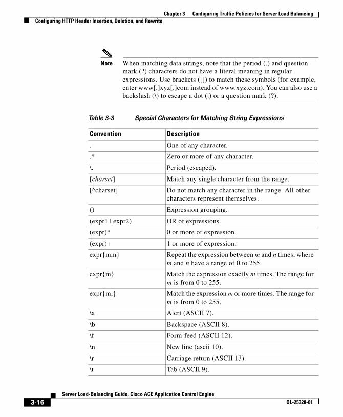
Note When matching data strings, note that the period (.) and question mark (?) characters do not have a literal meaning in regular expressions. Use brackets ([]) to match these symbols (for example, enter www[.]xyz[.]com instead of www.xyz.com). You can also use a backslash (\) to escape a dot (.) or a question mark (?).
Table 3-3 Special Characters for Matching String Expressions
Convention Description
. One of any character.
.* Zero or more of any character.
\. Period (escaped).
[charset] Match any single character from the range.
[^charset] Do not match any character in the range. All other characters represent themselves.
() Expression grouping.
(expr1 | expr2) OR of expressions.
(expr)* 0 or more of expression.
(expr)+ 1 or more of expression.
expr{m,n} Repeat the expression between m and n times, where m and n have a range of 0 to 255.
expr{m} Match the expression exactly m times. The range for m is from 0 to 255.
expr{m,} Match the expression m or more times. The range for m is from 0 to 255.
\a Alert (ASCII 7).
\b Backspace (ASCII 8).
\f Form-feed (ASCII 12).
\n New line (ascii 10).
\r Carriage return (ASCII 13).
\t Tab (ASCII 9).
3-16Server Load-Balancing Guide, Cisco ACE Application Control Engine
OL-25328-01

Chapter 3 Configuring Traffic Policies for Server Load BalancingConfiguring HTTP Header Insertion, Deletion, and Rewrite
For example, to insert a Host: source_ip:source_port in both the client request and the server response headers, enter:
host1/Admin(config)# action-list type modify http HTTP_MODIFY_ACTLISThost1/Admin(config-actlist-mod)# header insert both Host header-value %is:%ps
To associate the action list with a Layer 7 load-balancing policy map, enter:
host1/Admin(config)# policy-map type loadbalance http first-match L7_POLICYhost1/Admin(config-pmap-lb)# class L7_CLASShost1/Admin(config-pmap-lb-c)# serverfarm sf1host1/Admin(config-pmap-lb-c)# action HTTP_MODIFY_ACTLIST
To remove the header insert command from the action list, enter:
host1/Admin(config-actlist-mod)# no header insert both Host header-value %is:%ps
Configuring HTTP Header RewriteYou can rewrite an HTTP header in request packets from a client, response packets from a server, or both, by using the header rewrite command in action list modify configuration mode. The syntax of this command is as follows:
header rewrite {request | response | both} header_name header-value expression replace pattern
\v Vertical tab (ASCII 11).
\0 Null (ASCII 0).
\\ Backslash.
\x## Any ASCII character as specified in two-digit hexadecimal notation.
\xST Stop metacharacter. For information on the use of this metacharacter, see the “Using the “\xST” Metacharacter in Regular Expressions for Layer 4 Generic Data Parsing” section.
Table 3-3 Special Characters for Matching String Expressions (continued)
Convention Description
3-17Server Load-Balancing Guide, Cisco ACE Application Control Engine
OL-25328-01

Chapter 3 Configuring Traffic Policies for Server Load BalancingConfiguring HTTP Header Insertion, Deletion, and Rewrite
The keywords and arguments are as follows:
• request—Specifies that the ACE rewrite an HTTP header string only in HTTP request packets from clients
• response—Specifies that the ACE rewrite an HTTP header string only in HTTP response packets from servers
• both—Specifies that the ACE rewrite an HTTP header string in both HTTP request packets and response packets
• header_name—Identifier of an HTTP header. Enter an unquoted text string with a maximum of 255 alphanumeric characters.
• header-value expression—Specifies the value of the HTTP header that you want to replace in request packets, response packets, or both. Enter a text string from 1 to 255 alphanumeric characters. The ACE supports the use of regexes for matching data strings. See Table 3-3 for a list of the supported characters that you can use in regular expressions. Use parenthesized expressions for dynamic replacement using %1 and %2 in the replacement pattern.
Note When matching data strings, note that the period (.) and question mark (?) characters do not have a literal meaning in regular expressions. Use brackets ([]) to match these symbols (for example, enter www[.]xyz[.]com instead of www.xyz.com). You can also use a backslash (\) to escape a dot (.) or a question mark (?).
• replace pattern—Specifies the pattern string that you want to substitute for the header value regular expression. For dynamic replacement of the first and second parenthesized expressions from the header value, use %1 and %2, respectively.
If there is no delimiting character between the partial match and the start of the full match, there may not be a sufficient regex action state change for the ACE to distinguish the start of the match. In this case, you may find that HTTP header rewrite does not function properly when a partial match repeats without a character in between. When this occurs the rewritten header fails to include the initial partial match characters.
This example illustrates this behavior. With the following header rewrite both command:
host1/Admin(config-actlist-mod)# header rewrite both NEW header-value (.*)http(.*) replace %1HTTPS%2
3-18Server Load-Balancing Guide, Cisco ACE Application Control Engine
OL-25328-01

Chapter 3 Configuring Traffic Policies for Server Load BalancingConfiguring HTTP Header Insertion, Deletion, and Rewrite
Note the HTTP header rewrite behavior for input headers “htabhttabhttpab” and “abhtthttpab”:
• The regular expression in this example functions properly for HTTP header “htabhttabhttpab” and would be rewritten as HTTP header “htabhttabhttpsab”. The ACE supports partial match characters before the match pattern “http” as long as the immediate prefix to that string is not a partial match.
• However, for HTTP header “abhtthttpab”, this partial match HTTP pattern would be rewritten as HTTP header “abhttpsab”. Since there is no delimiting character between the partial match and the start of full match, the ACE is unable to distinguish the start of the proper match.
To avoid this HTTP header rewrite behavior, we recommend that you include the prefix in the match pattern if that is the expected pattern. In this case. change the regex match to “(.*)htthttp(.*)” to include a prefix and ensure that there is a delimiter before the match.
For example, to replace www.cisco.com with www.cisco.net, enter:
host1/Admin(config)# action-list type modify http HTTP_MODIFY_ACTLISThost1/Admin(config-actlist-mod)# header rewrite request Host header-value www\.(cisco)\.com replace www.%1.net
To associate the action list with a Layer 7 load-balancing policy map, enter:
host1/Admin(config)# policy-map type loadbalance http first-match L7_POLICYhost1/Admin(config-pmap-lb)# class L7_CLASShost1/Admin(config-pmap-lb-c)# serverfarm sf1host1/Admin(config-pmap-lb-c)# action HTTP_MODIFY_ACTLIST
To remove the header rewrite command from the action list, enter:
host1/Admin(config-actlist-mod)# no header rewrite request Host header-value www\.(cisco)\.com replace www.%1.net
Configuring HTTP Header DeletionYou can delete an HTTP header in a request from a client, in a response from a server, or both, by using the header delete command in action list modify configuration mode. The syntax of this command is as follows:
header delete {request | response | both} header_name header-value value
3-19Server Load-Balancing Guide, Cisco ACE Application Control Engine
OL-25328-01

Chapter 3 Configuring Traffic Policies for Server Load BalancingConfiguring HTTP Header Insertion, Deletion, and Rewrite
The keywords and arguments are as follows:
• request—Specifies that the ACE delete the header only in HTTP request packets from clients
• response—Specifies that the ACE delete the header only in HTTP response packets from servers
• both—Specifies that the ACE delete the header in both HTTP request packets and response packets
• header_name—Identifier of an HTTP header that you want to delete. Enter an unquoted text string with a maximum of 255 alphanumeric characters.
• header-value value—Deletes the specified HTTP header that matches the specified header value.
For example, to delete the Host header from request packets only, enter:
host1/Admin(config)# action-list type modify http HTTP_MODIFY_ACTLISThost1/Admin(config-actlist-mod)# header delete request Host
To associate the action list with a Layer 7 load-balancing policy map, enter:
host1/Admin(config)# policy-map type loadbalance http first-match L7_POLICYhost1/Admin(config-pmap-lb)# class L7_CLASShost1/Admin(config-pmap-lb-c)# serverfarm sf1host1/Admin(config-pmap-lb-c)# action HTTP_MODIFY_ACTLIST
To remove the header delete command from the action list, enter:
host1/Admin(config-actlist-mod)# no header delete request Host
Defining a Description for an Action ListYou can provide a brief summary for an action list by using the description command in action list modify configuration mode. The syntax of this command is as follows:
description text
For the text argument, enter an unquoted text string with a maximum of 240 alphanumeric characters including spaces.
For example, to specify a description, enter the following command:
3-20Server Load-Balancing Guide, Cisco ACE Application Control Engine
OL-25328-01

Chapter 3 Configuring Traffic Policies for Server Load BalancingConfiguring the Compilation Timeout for Regular Expressions
host1/Admin(config)# action-list type modify http HTTP_MODIFY_ACTLISThost1/Admin(config-actlist-mod)# description HTTP action list with delete request
To remove the description, enter:
host1/Admin(config-actlist-mod)# no description
Configuring the Compilation Timeout for Regular Expressions
To configure the timeout for regex compilation, use the regex compilation-timeout command in configuration mode. When you configure a regex and its compilation is longer than the configured timeout, the ACE stops the regex compilation. The syntax for this command is as follows:
regex compilation-timeout minutes
The minutes argument is the time period in minutes. Enter an integer from 1 to 500. The default timeout is 60 minutes. This command is available only in the Admin context for an admin role and is applicable across all contexts.
For example, to configure a compilation timeout of 80 minutes, enter the following command:
host/Admin(config)# regex compilation-timeout 80
To reset the regex compilation timeout to the default value of 60 minutes, enter the following command:
host/Admin(config)# no regex compilation-timeout
3-21Server Load-Balancing Guide, Cisco ACE Application Control Engine
OL-25328-01

Chapter 3 Configuring Traffic Policies for Server Load BalancingConfiguring a Layer 7 Class Map for Generic TCP and UDP Data Parsing
Configuring a Layer 7 Class Map for Generic TCP and UDP Data Parsing
You can use generic TCP and UDP data parsing to perform regular expression (regex) matches on packets from protocols that the ACE does not explicitly support. Such regex matches can be based on a custom protocol configuration. To accomplish this task, you create a Layer 7 class map for generic TCP or UDP data parsing and then instruct the ACE to perform a policy-map action based on the payload of a TCP stream or UDP packet.
To avoid using a large amount of memory with regular expressions, we recommend the following guidelines when you configure generic data parsing:
• Use only one generic rule per VIP
• Use the same offset for all generic rules on the same VIP
• Use the smallest possible offset that will work for your application
• Avoid deploying Layer 4 payload stickiness (see Chapter 5, Configuring Stickiness) and Layer 4 payload matching simultaneously, when possible
Note The persistence-rebalance command is not compatible with generic protocol parsing.
You can create a class map for generic TCP or UDP data parsing by using the class-map type generic command in configuration mode. The syntax of this command is as follows:
class-map type generic match-all | match-any name
The keywords and arguments are as follows:
• generic—Specifies nonprotocol-specific behavior for data parsing
• match-all | match-any—(Optional) Determines how the ACE evaluates Layer 3 and Layer 4 network traffic when multiple match criteria exist in a class map. The class map is considered a match if the match commands meet one of the following conditions.
– match-all—(Default) Network traffic needs to satisfy all of the match criteria (implicit AND) to match the class map.
3-22Server Load-Balancing Guide, Cisco ACE Application Control Engine
OL-25328-01

Chapter 3 Configuring Traffic Policies for Server Load BalancingConfiguring a Layer 7 Class Map for Generic TCP and UDP Data Parsing
– match-any—Network traffic needs to satisfy only one of the match criteria (implicit OR) to match the load-balancing class map.
• name—Name assigned to the class map. Enter an unquoted text string with no spaces and a maximum of 64 alphanumeric characters. The name is used for both the class map and to associate the class map with a policy map.
For example, enter:
host1/Admin(config)# class-map type generic match-any GENERIC_L7_CLASS
To remove the class map from the configuration, enter:
host1/Admin(config)# no class-map type generic match-any GENERIC_L7_CLASS
After you create a class map for generic protocol parsing, configure one or more match statements as described in the following sections:
• Defining Layer 4 Payload Match Criteria for Generic Data Parsing
• Using the “\xST” Metacharacter in Regular Expressions for Layer 4 Generic Data Parsing
• Defining Source IP Address Match Criteria
Defining Layer 4 Payload Match Criteria for Generic Data ParsingGeneric data parsing begins at Layer 4 with the TCP or UDP payload, which allows you to match Layer 5 data (in the case of Lightweight Directory Access Protocol (LDAP) or DNS or any Layer 7 header or payload (for example, HTTP). You can define match criteria for Layer 4 payloads by using the match layer4-payload command in class-map generic configuration mode. The syntax of this command is as follows:
[line_number] match layer4-payload [offset number] | regex expression
Note You cannot configure more than one match layer4-payload command in the same match-all class map.
The keywords, options, and arguments are as follows:
3-23Server Load-Balancing Guide, Cisco ACE Application Control Engine
OL-25328-01

Chapter 3 Configuring Traffic Policies for Server Load BalancingConfiguring a Layer 7 Class Map for Generic TCP and UDP Data Parsing
• line_number—(Optional) Line numbers that you can use for editing or deleting the individual match commands. For example, you can enter no line_number to delete long match commands instead of entering the entire line. The sequence numbers do not indicate any priority for the match statements. Enter a unique integer from 2 to 1024.
• offset number—(Optional) Specifies an absolute offset in the data where the Layer 4 payload expression search string starts. The offset starts at the first byte of the TCP or UDP body. Enter an integer from 0 to 999. The default is 0.
• regex expression—Specifies the Layer 4 payload expression that is contained within the TCP or UDP entity body. The ACE supports the use of regexes for matching data strings. See Table 3-3 for a list of the supported characters that you can use in regular expressions. Use parenthesized expressions for dynamic replacement using %1 and %2 in the replacement pattern.
For information on the use of the “\xST” (STop) metacharacter for regular expressions, see the “Using the “\xST” Metacharacter in Regular Expressions for Layer 4 Generic Data Parsing” section.
Note When matching data strings, note that the period (.) and question mark (?) characters do not have a literal meaning in regular expressions. Use brackets ([]) to match these symbols (for example, enter www[.]xyz[.]com instead of www.xyz.com). You can also use a backslash (\) to escape a dot (.) or a question mark (?).
Note You can associate a maximum of 1024 instances of the same type of regex with a a Layer 4 policy map. This limit applies to all Layer 7 policy-map types, including generic, HTTP, RADIUS, RDP, RTSP, and SIP. You configure regexes in the following:
• Match statements in Layer 7 class maps
• Inline match statements in Layer 7 policy maps
• Layer 7 hash predictors for server farms
• Layer 7 sticky expressions in sticky groups
• Header insertion and rewrite (including SSL URL rewrite) expressions in Layer 7 action lists
3-24Server Load-Balancing Guide, Cisco ACE Application Control Engine
OL-25328-01

Chapter 3 Configuring Traffic Policies for Server Load BalancingConfiguring a Layer 7 Class Map for Generic TCP and UDP Data Parsing
For example, to create a class map for generic Layer 4 data parsing, enter:
host1/Admin(config)# class-map type generic match-any GENERIC_L7_CLASShost1/Admin(config-cmap-generic)# 10 match layer4-payload offset 500 regex abc123
To remove the match statement from the class map, enter:
host1/Admin(config-cmap-generic)# no 10
Using the “\xST” Metacharacter in Regular Expressions for Layer 4 Generic Data Parsing
This section describes the use of the “\xST” metacharacter for regular expressions that are used as part of Layer 4 generic data parsing. It includes the following topics:
• Overview
• “\xST” Metacharacter Regex Usage Considerations
• Configuration Examples
Overview
The ACE supports the “\xST” (STop) metacharacter for all regular expressions (regexes) in specific cases that use the maximum parse length to terminate parsing. However, the “\xST” metacharacter is specifically for use by applications that involve the generic data parsing of a Layer 4 payload.
If you intend to use the “\xST” metacharacter for regex matches on packets from protocols, we recommend that you use this metacharacter only for the following protocols in the generic data parsing of a Layer 4 payload:
• SSL session-ID stickiness—To perform sticky hashing on the initial packets in an SSL handshake, allowing the ACE to stick the same client to the same SSL server based on the SSL session ID.
• Financial Information eXchange (FIX) type ‘A’ Logon message—To define load-balancing criteria while setting up the outbound path of a connection.
3-25Server Load-Balancing Guide, Cisco ACE Application Control Engine
OL-25328-01

Chapter 3 Configuring Traffic Policies for Server Load BalancingConfiguring a Layer 7 Class Map for Generic TCP and UDP Data Parsing
The inclusion of the “\xST” metacharacter aids the ACE in properly load-balancing SSL session-ID and FIX packets. Without the “\xST” metacharacter in regexes, certain SSL session-ID and FIX packets may get stuck in the ACE HTTP engine and eventually time out the connection.
“\xST” Metacharacter Regex Usage Considerations
The “\xST” metacharacter has the following usage guidelines related to its inclusion in regex matching:
• If the input matches a regex pattern that includes the “\xST” metacharacter, the regex engine halts upon finding the character directly next to the '\xST' in the regex string (2nd '\x01' in the match statement).
• Only use the “\xST” metacharacter once in the policy. The ACE does not consider any additional input data once it sees the matching pattern, which may affect other regexes that are configured elsewhere in the policy.
• Only use the “\xST” metacharacter at the end of a regex pattern; not at the beginning. Otherwise, the ACE will display the “Error: Invalid regular expression” error message.
• Do not add the “\xST” metacharacter directly after a * wildcard match. For example, “abc.*\xST” is not be a recommended regex.
Configuration Examples
The following configuration examples show the use of the “\xST” metacharacter in two very specific regexes:
SSL Session-ID Stickiness Configuration Exampleparameter-map type generic SESSID-PARAM
set max-parse-length 76
sticky layer4-payload SESSID-STICKY serverfarm SF1 response sticky layer4-payload offset 43 length 32 begin-pattern "(\x20|\x00\xST)"
FIX Protocol Configuration Examplesticky layer4-payload FIX-STICKY
3-26Server Load-Balancing Guide, Cisco ACE Application Control Engine
OL-25328-01

Chapter 3 Configuring Traffic Policies for Server Load BalancingConfiguring a Layer 7 Class Map for Generic TCP and UDP Data Parsing
serverfarm FIX-SF1layer4-payload begin-pattern "\x0149=" end-pattern "\x01"
class-map type generic match-all FIX-CM2 match layer4-payload regex ".*\x0110=...\x01\xST"
Defining Source IP Address Match CriteriaYou can configure the class map to filter traffic based on a client source IP address by using the match source-address command in class map generic configuration mode. If this command is the only match criteria in the class map, it is considered to be a Layer 3 and Layer 4 class map.
IPv6 Syntax and Examples
The syntax of this command is as follows:
[line_number] match source-address ipv6_address [/prefix_length]
The arguments and options are as follows:
• line_number—(Optional) Line numbers that you can use for editing or deleting the individual match commands. For example, you can enter no line_number to delete long match commands instead of entering the entire line. The line numbers do not indicate any priority for the match statements. Enter a unique integer from 2 to 1024.
• ipv6_address—Source IPv6 address of the client. Enter the IP address in IPv6 format.
• /prefix_length—(Optional) Specifies how many of the most significant bits (MSBs) of the IPv6 address are used for the network identifier. Enter a a forward slash character (/) followed by an integer from 1 to 128. The default is /128.
Note You cannot configure more than one match source-address command in the same match-all class map.
For example, to specify that the class map match on source IP address 2001:DB8:1::1/64, enter:
3-27Server Load-Balancing Guide, Cisco ACE Application Control Engine
OL-25328-01

Chapter 3 Configuring Traffic Policies for Server Load BalancingConfiguring a Layer 7 Class Map for Generic TCP and UDP Data Parsing
host1/Admin(config)# class-map type generic match-any GENERIC_L4_CLASShost1/Admin(config-cmap-generic)# 50 match source-address 2001:DB8:1::1/64
To remove the source IP address match statement from the class map, enter:
host1/Admin(config-cmap-generic)# no 50
IPv4 Syntax and Examples
The syntax of this command is as follows:
[line_number] match source-address ip_address [netmask]
The arguments and options are as follows:
• line_number—(Optional) Line numbers that you can use for editing or deleting the individual match commands. For example, you can enter no line_number to delete long match commands instead of entering the entire line. The line numbers do not indicate any priority for the match statements. Enter a unique integer from 2 to 1024.
• ip_address—Source IPv4 address of the client. Enter the IPv4 address in dotted-decimal notation (for example, 192.168.11.2).
• netmask—(Optional) Subnet mask of the Iv4P address. Enter the netmask in dotted-decimal notation (for example, 255.255.255.0). The default is 255.255.255.255.
Note You cannot configure more than one match source-address command in the same match-all class map.
For example, to specify that the class map match on source IP address 192.168.11.2 255.255.255.0, enter:
host1/Admin(config)# class-map type generic match-any GENERIC_L4_CLASShost1/Admin(config-cmap-generic)# 50 match source-address 192.168.11.2 255.255.255.0
To remove the source IP address match statement from the class map, enter:
host1/Admin(config-cmap-generic)# no 50
3-28Server Load-Balancing Guide, Cisco ACE Application Control Engine
OL-25328-01

Chapter 3 Configuring Traffic Policies for Server Load BalancingConfiguring a Layer 7 Class Map for Generic TCP and UDP Data Parsing
Nesting Layer 7 SLB Class MapsThe nesting of class maps allows you to achieve complex logical expressions for generic parsing.You can identify one generic class map that is to be used as a matching criterion for another generic class map by using the match class-map command in class-map generic configuration mode.
Note The ACE restricts the nesting of class maps to two levels to prevent you from including a nested class map under another class map.
The syntax of this command is as follows:
[line_number] match class-map map_name
The keywords, arguments, and options are as follows:
• line_number—(Optional) Line numbers that you can use for editing or deleting the individual match commands. For example, you can enter no line_number to delete long match commands instead of entering the entire line.
• map_name—Name of an existing generic class map.
The match class-map command allows you to combine the use of the match-any and match-all keywords in the same class map. To combine match-all and match-any characteristics in a class map, create a class map that uses one match command (either match any or match all), and then use this class map as a match statement in a second class map that uses a different match type.
For example, assume that commands A, B, C, and D represent separate match criteria, and you want generic protocol traffic that matches A, B, or C and D (A or B or [C and D]) to satisfy the class map. Without the use of nested class maps, traffic would either have to match all four match criteria (A and B and C and D) or match any of the match criteria (A or B or C or D) to satisfy the class map. By creating a single class map that uses the match-all keyword for match criteria C and D (criteria E), you can then create a new match-any class map that uses match criteria A, B, and E. The new traffic class contains your desired classification sequence: A or B or E, which is equivalent to A or B or [C and D].
3-29Server Load-Balancing Guide, Cisco ACE Application Control Engine
OL-25328-01

Chapter 3 Configuring Traffic Policies for Server Load BalancingConfiguring a Layer 7 Class Map for Generic TCP and UDP Data Parsing
IPv6 Example
To combine the characteristics of two class maps, one with match-any and one with match-all characteristics, into a single class map by using the match class-map command, enter:
host1/Admin(config)# class-map type generic match-any GENERIC_L4_CLASShost1/Admin(config-cmap-generic)# 50 match source-address 2001:DB8:1::1/64host1/Admin(config-cmap-generic)# exit
host1/Admin(config)# class-map type generic match-all GENERIC_L4_CLASShost1/Admin(config-cmap-generic)# 10 match class-map GENERIC_L4_CLASS2host1/Admin(config-cmap-generic)# 20 match source-address 2001:DB8:1::1host1/Admin(config-cmap-generic)# exit
To remove the nested class map from the generic class map, enter:
host1/Admin(config-cmap-generic)# no 10
IPv4 Example
To combine the characteristics of two class maps, one with match-any and one with match-all characteristics, into a single class map by using the match class-map command, enter:
host1/Admin(config)# class-map type generic match-any GENERIC_L4_CLASShost1/Admin(config-cmap-generic)# 50 match source-address 192.168.11.2 255.255.255.0host1/Admin(config-cmap-generic)# exit
host1/Admin(config)# class-map type generic match-all GENERIC_L4_CLASShost1/Admin(config-cmap-generic)# 10 match class-map GENERIC_L4_CLASS2host1/Admin(config-cmap-generic)# 20 match source-address 192.168.11.2host1/Admin(config-cmap-generic)# exit
To remove the nested class map from the generic class map, enter:
host1/Admin(config-cmap-generic)# no 10
3-30Server Load-Balancing Guide, Cisco ACE Application Control Engine
OL-25328-01

Chapter 3 Configuring Traffic Policies for Server Load BalancingConfiguring a Layer 7 Class Map for SLB
Configuring a Layer 7 Class Map for SLBA Layer 7 SLB class map contains match criteria that classify specific Layer 7 network traffic. This section describes how to create a class map for Layer 7 SLB based on HTTP cookies, HTTP headers, HTTP URLs, SSL cipher encryption level, RADIUS attributes, RDP, RTSP headers or URLs, SIP headers, or source IP addresses.
You can create a Layer 7 class map for SLB and enter the class-map configuration mode by using the class-map type command in configuration mode. The syntax of this command is as follows:
class-map type {{http | radius | rtsp | sip} loadbalance} [match-all | match-any] map_name
You can configure multiple match commands in a single class map to specify the matching criteria. For example, you can configure a Layer 7 load-balancing class map to define multiple URLs, cookies, and HTTP headers in a group that you then associate with a traffic policy. The match-all and match-any keywords determine how the ACE evaluates multiple match statement operations when multiple match criteria exist in a class map.
The keywords, arguments, and options are as follows:
• http—Specifies a Hypertext Transfer Protocol (HTTP) load-balancing class map. This is the default.
• radius—Specifies the Remote Access Dial-In User Service (RADIUS) protocol for load balancing.
• rtsp—Specifies the Real-Time Streaming Protocol (RTSP) for load balancing.
• sip—Specifies the Session Initiation Protocol (SIP) for load balancing.
• loadbalance—Specifies a load-balancing type class map.
• match-all | match-any—(Optional) Determines how the ACE evaluates Layer 7 HTTP SLB operations when multiple match criteria exist in a class map. The class map is considered a match if the match commands meet one of the following conditions:
– match-all —(Default) Network traffic needs to satisfy all of the match criteria (implicit AND) to match the Layer 7 load-balancing class map. The match-all keyword is applicable only for match statements of
3-31Server Load-Balancing Guide, Cisco ACE Application Control Engine
OL-25328-01

Chapter 3 Configuring Traffic Policies for Server Load BalancingConfiguring a Layer 7 Class Map for SLB
different Layer 7 load-balancing types. For example, specifying a match-all condition for URL, HTTP header, and URL cookie statements in the same class map is valid. However, specifying a match-all condition for multiple HTTP headers or multiple cookies with the same names or multiple URLs in the same class map is invalid.
– match-any—Network traffic needs to satisfy only one of the match criteria (implicit OR) to match the HTTP load-balancing class map. The match-any keyword is applicable only for match statements of the same Layer 7 load-balancing type. For example, the ACE does not allow you to specify a match-any condition for URL, HTTP header, and URL cookie statements in the same class map but does allow you to specify a match-any condition for multiple URLs, multiple HTTP headers, or multiple cookies with different names in the same class map.
• map_name—Unique identifier assigned to the class map. Enter an unquoted text string with no spaces and a maximum of 64 alphanumeric characters. The class-map name is used for both the class map and to associate the class map with a policy map.
For example, to create a Layer 7 load-balancing class map named L7SLBCLASS, enter:
host1/Admin(config)# class-map type http loadbalance match-any L7SLBCLASShost1/Admin(config-cmap-http-lb)#
To remove a Layer 7 load-balancing class map from the configuration, enter:
host1/Admin(config)# no class-map type http loadbalance match-any L7SLBCLASS
The following topics describe how to specify match criteria for the Layer 7 class map:
• Configuration Considerations
• Defining an HTTP Content Match for Load Balancing
• Defining a Cookie for HTTP Load Balancing
• Defining an HTTP Header for Load Balancing
• Defining a URL for HTTP Load Balancing
• Defining an SSL Cipher-Based Encryption Level for HTTP Load Balancing
• Excluding Files with Specific Extensions/MIME Types When Performing Regular Expression Matching and HTTP Compression
3-32Server Load-Balancing Guide, Cisco ACE Application Control Engine
OL-25328-01

Chapter 3 Configuring Traffic Policies for Server Load BalancingConfiguring a Layer 7 Class Map for SLB
• Defining an Attribute for RADIUS Load Balancing
• Defining a Header for RTSP Load Balancing
• Defining a URL for RTSP Load Balancing
• Defining a Header for SIP Load Balancing
• Defining Source IP Address Match Criteria
• Nesting Layer 7 SLB Class Maps
Configuration ConsiderationsWhen you are creating a class map for SLB, note the following restrictions:
• You can associate a maximum of 10 cookie names and header names with each Layer 3 and Layer 4 policy map. You can allocate the number of cookie names and header names in any combination as long as you do not exceed the maximum of 10.
• You can associate a maximum of 1024 instances of the same type of regex with each Layer 3 and Layer 4 policy map. This limit applies to all Layer 7 policy-map types, including generic, HTTP, RADIUS, RDP, RTSP, and SIP. You configure regexes in the following:
– Match statements in Layer 7 class maps
– Inline match statements in Layer 7 policy maps
– Layer 7 hash predictors for server farms
– Layer 7 sticky expressions in sticky groups
– Header insertion and rewrite (including SSL URL rewrite) expressions in Layer 7 action lists
• The ACE restricts the nesting of class maps to two levels to prevent you from including one nested class map in a different class map.
• The maximum number of class maps for each ACE is 8192.
3-33Server Load-Balancing Guide, Cisco ACE Application Control Engine
OL-25328-01

Chapter 3 Configuring Traffic Policies for Server Load BalancingConfiguring a Layer 7 Class Map for SLB
Defining an HTTP Content Match for Load BalancingThe ACE performs regular expression matching against the received HTTP message body from a particular connection based on a regular expression string in the message body (not the header). To configure the class map to make Layer 7 SLB decisions based on the HTTP content, use the match http content command in class-map configuration mode. The syntax of this command is as follows:
[line_number] match http content expression [offset number]
The arguments and options are as follows:
• line_number—(Optional) Line numbers that you can use for editing or deleting the individual match commands. For example, you can enter no line_number to delete long match commands instead of entering the entire line. The line numbers do not indicate any priority for the match statements. Enter a unique integer from 2 to 1024.
• expression—The regular expression content to match. Enter a string from 1 to 255 alphanumeric characters. The ACE supports the use of regular expressions for matching data strings. See Table 3-3 for a list of the supported characters that you can use in regular expressions.
Note When matching data strings, note that the period (.) and question mark (?) characters do not have a literal meaning in regular expressions. Use brackets ([]) to match these symbols (for example, enter www[.]xyz[.]com instead of www.xyz.com). You can also use a backslash (\) to escape a dot (.) or a question mark (?).
• offset number—(Optional) Specifies the byte at which the ACE begins parsing the message body. Enter an integer from 0 to 999. The default is 0.
For example, enter:
host1/Admin(config)# class-map type http loadbalance match-any L7_HTTP_CLASShost1/Admin(config-cmap-http-lb)# 10 match http content abc*123 offset 50
3-34Server Load-Balancing Guide, Cisco ACE Application Control Engine
OL-25328-01

Chapter 3 Configuring Traffic Policies for Server Load BalancingConfiguring a Layer 7 Class Map for SLB
Defining a Cookie for HTTP Load BalancingThe ACE performs regular expression matching against the received packet data from a particular connection based on the cookie expression. You can configure a maximum of 10 cookie names and header names per class in any combination. You can configure the class map to make Layer 7 SLB decisions based on the name and string of a cookie by using the match http cookie command in class-map configuration mode. The syntax of this command is as follows:
[line_number] match http cookie {name | secondary name} cookie-value expression
The keywords, arguments, and options are as follows:
• line_number—(Optional) Line numbers that you can use for editing or deleting the individual match commands. For example, you can enter no line_number to delete long match commands instead of entering the entire line. The sequence numbers do not indicate any priority for the match statements. Enter a unique integer from 2 to 1024.
• name—Unique cookie name. Enter an unquoted text string with no spaces and a maximum of 64 alphanumeric characters.
Note If certain characters are used in the cookie name, such as an underscore (_), hyphen (-), period (.), or semicolon (:), replace those characters with the equivalent percent encoding (% HEX HEX) characters. For example, to configure the cookie name Regex_MatchCookie, replace the underscore (_) character with the equivalent %5F percent encoding character and enter the cookie name as Regex%5FMatchCookie in the CLI.
• secondary name—Specifies a cookie in a URL string. You can specify the delimiters for cookies in a URL string using a command in an HTTP parameter map. For more information, see the “Defining Secondary Cookie Delimiters in a URL” section.
• cookie-value expression—Specifies a unique cookie value regular expression. Enter an unquoted text string with no spaces and a maximum of 255 alphanumeric characters. Alternatively, you can enter a text string with spaces provided that you enclose the entire string in quotation marks (“). The
3-35Server Load-Balancing Guide, Cisco ACE Application Control Engine
OL-25328-01

Chapter 3 Configuring Traffic Policies for Server Load BalancingConfiguring a Layer 7 Class Map for SLB
ACE supports the use of regular expressions for matching string expressions. See Table 3-3 for a list of the supported characters that you can use for matching string expressions.
Note When matching data strings, note that the period (.) and question mark (?) characters do not have a literal meaning in regular expressions. Use brackets ([]) to match these symbols (for example, enter www[.]xyz[.]com instead of www.xyz.com). You can also use a backslash (\) to escape a dot (.) or a question mark (?).
For example, to specify that the Layer 7 class map load balance on a cookie with the name of testcookie1, enter:
host1/Admin(config)# class-map type http loadbalance match-any L7SLBCLASShost1/Admin(config-cmap-http-lb)# 100 match http cookie testcookie1 cookie-value 123456
To remove an HTTP cookie match statement from the class map, enter:
host1/Admin(config-cmap-http-lb)# no 100
Defining an HTTP Header for Load BalancingThe ACE performs regular expression matching against the received packet data from a particular connection based on the HTTP header expression. You can configure a maximum of 10 HTTP header names and cookie names per class in any combination. To configure a class map to make Layer 7 SLB decisions based on the name and value of an HTTP header, use the match http header command in class-map HTTP load balance configuration mode.
The syntax of this command is as follows:
[line_number] match http header name header-value expression
3-36Server Load-Balancing Guide, Cisco ACE Application Control Engine
OL-25328-01

Chapter 3 Configuring Traffic Policies for Server Load BalancingConfiguring a Layer 7 Class Map for SLB
The keywords, arguments, and options are as follows:
• line_number—(Optional) Line numbers that you can use for editing or deleting the individual match commands. For example, you can enter no line_number to delete long match commands instead of entering the entire line. The sequence numbers do not indicate any priority for the match statements. Enter a unique integer from 2 to 1024.
• name—Name of the field in the HTTP header. Enter an unquoted text string with no spaces and a maximum of 64 alphanumeric characters. Alternatively, you can enter a text string with spaces if you enclose the entire string in quotation marks (“). You can enter any header field name, including a standard HTTP header field name or any user-defined header field name. For a list of standard HTTP header field names, see Table 3-4.
• header-value expression—Specifies the header value regular expression string to compare against the value in the specified field in the HTTP header. Enter a text string with a maximum of 255 alphanumeric characters. The ACE supports the use of regular expressions for header matching. Expressions are stored in a header map in the form header-name: expression. Header expressions allow spaces, provided that the entire string that contains spaces is quoted. If you use a match-all class map, all headers in the header map must be matched. See Table 3-3 for a list of the supported characters that you can use in regular expressions.
Note When matching data strings, note that the period (.) and question mark (?) characters do not have a literal meaning in regular expressions. Use brackets ([]) to match these symbols (for example, enter www[.]xyz[.]com instead of www.xyz.com). You can also use a backslash (\) to escape a dot (.) or a question mark (?).
3-37Server Load-Balancing Guide, Cisco ACE Application Control Engine
OL-25328-01

Chapter 3 Configuring Traffic Policies for Server Load BalancingConfiguring a Layer 7 Class Map for SLB
Table 3-4 Standard HTTP Header Fields
Field Name Description
Accept Semicolon-separated list of representation schemes (content type metainformation values) that will be accepted in the response to the request.
Accept-Charset Character sets that are acceptable for the response. This field allows clients capable of understanding more comprehensive or special-purpose character sets to signal that capability to a server that can represent documents in those character sets.
Accept-Encoding Restricts the content encoding that a user will accept from the server.
Accept-Language ISO code for the language in which the document is written. The language code is an ISO 3316 language code with an optional ISO639 country code to specify a national variant.
Authorization Specifies that the user agent wants to authenticate itself with a server, usually after receiving a 401 response.
Cache-Control Directives that must be obeyed by all caching mechanisms along the request/response chain. The directives specify behavior intended to prevent caches from adversely interfering with the request or response.
Connection Allows the sender to specify connection options.
Content-MD5 MD5 digest of the entity-body that provides an end-to-end integrity check. Only a client or an origin server can generate this header field.
Expect Used by a client to inform the server about what behaviors the client requires.
From E-mail address of the person that controls the requesting user agent.
3-38Server Load-Balancing Guide, Cisco ACE Application Control Engine
OL-25328-01

Chapter 3 Configuring Traffic Policies for Server Load BalancingConfiguring a Layer 7 Class Map for SLB
Host Internet host and port number of the resource being requested, as obtained from the original URI given by the user or referring resource. The Host field value must represent the naming authority of the origin server or gateway given by the original URL.
If-Match Used with a method to make it conditional. A client that has one or more entities previously obtained from the resource can verify that one of those entities is current by including a list of their associated entity tags in the If-Match header field. This feature allows efficient updates of cached information with a minimum amount of transaction overhead. It is also used on updating requests to prevent inadvertent modification of the wrong version of a resource. As a special case, the value “*” matches any current entity of the resource.
Pragma Pragma directives understood by servers to whom the directives are relevant. The syntax is the same as for other multiple-value fields in HTTP, for example, the accept field, a comma-separated list of entries, for which the optional parameters are separated by semicolons.
Referer Address (URI) of the resource from which the URI in the request was obtained.
Transfer-Encoding What (if any) type of transformation has been applied to the message body in order to safely transfer it between the sender and the recipient.
Table 3-4 Standard HTTP Header Fields (continued)
Field Name Description
3-39Server Load-Balancing Guide, Cisco ACE Application Control Engine
OL-25328-01

Chapter 3 Configuring Traffic Policies for Server Load BalancingConfiguring a Layer 7 Class Map for SLB
For example, to specify that the Layer 7 class map load balance on an HTTP header named Host, enter:
host1/Admin(config)# class-map type http loadbalance match-any L7SLBCLASShost1/Admin(config-cmap-http-lb)# 100 match http header Host header-value .*cisco.com
For example, to use regular expressions in a class map to emulate a wildcard search to match the header value expression string, enter:
host1/Admin(config)# class-map type http loadbalance match-any L7SLBCLASShost1/Admin(config-cmap-http-lb)# 10 match http header Host header-value .*cisco.comhost1/Admin(config-cmap-http-lb)# 20 match http header Host header-value .*yahoo.com
For example, to specify that the Layer 7 class map load balance on an HTTP header named Via, enter:
host1/Admin(config)# class-map type http loadbalance match-any L7SLBCLASShost1/Admin(config-cmap-http-lb)# 200 match http header Via header-value 192.*
To remove HTTP header match criteria from the L7SLBCLASS class map, enter:
host1/Admin(config-cmap-http-lb)# no 10host1/Admin(config-cmap-http-lb)# no 20
User-Agent Information about the user agent, for example, a software program originating the request. This information is for statistical purposes, the tracing of protocol violations, and automated recognition of user agents to customize responses to avoid particular user agent limitations.
Via Used by gateways and proxies to indicate the intermediate protocols and recipients between the user agent and the server on requests and between the origin server and the client on responses.
Table 3-4 Standard HTTP Header Fields (continued)
Field Name Description
3-40Server Load-Balancing Guide, Cisco ACE Application Control Engine
OL-25328-01
Chapter 3 Configuring Traffic Policies for Server Load BalancingConfiguring a Layer 7 Class Map for SLB
Defining a URL for HTTP Load BalancingThe ACE performs regular expression matching against the received packet data from a particular connection based on the HTTP URL string. To configure a class map to make Layer 7 SLB decisions based on the URL name and, optionally, the HTTP method, use the match http url command in class-map HTTP load balance configuration mode. The syntax of this command is as follows:
[line_number] match http url expression [method name]
The keywords, arguments, and options are as follows:
• line_number—(Optional) Line numbers that you can use for editing or deleting the individual match commands. For example, you can enter no line_number to delete long match commands instead of entering the entire line. The line_number line numbers do not indicate any priority for the match statements. Enter a unique integer from 2 to 1024.
• expression—URL, or portion of a URL, to match. Enter a URL string from 1 to 255 alphanumeric characters. The ACE performs matching on whatever URL string appears after the HTTP method, regardless of whether the URL includes the hostname. The ACE supports the use of regular expressions for matching URL strings. See Table 3-3 for a list of the supported characters that you can use in regular expressions.
Note When matching URLs, note that the period (.) and question mark (?) characters do not have a literal meaning in regular expressions. Use brackets ([]) to match these symbols (for example, enter www[.]xyz[.]com instead of www.xyz.com). You can also use a backslash (\) to escape a dot (.) or a question mark (?).
• method name—(Optional) Specifies the HTTP method to match. Enter a method name as an unquoted text string with no spaces and a maximum of 64 alphanumeric characters. The method can either be one of the standard HTTP 1.1 method names (OPTIONS, GET, HEAD, POST, PUT, DELETE, TRACE, or CONNECT) or a text string that must be matched exactly (for example, CORVETTE).
3-41Server Load-Balancing Guide, Cisco ACE Application Control Engine
OL-25328-01

Chapter 3 Configuring Traffic Policies for Server Load BalancingConfiguring a Layer 7 Class Map for SLB
Using the configured match http url expression command, the ACE attempts to match a URL in an HTTP request following the first space after the request method. For example, if the request were “GET /index.html HTTP/1.1”, the ACE tries to match starting with the “/” character. Therefore, the class-map match statement is conformant with the RFCs that cover HTTP URI syntax. This syntax includes request URIs that start either with “/” or with "scheme://authority/" (for example, http://www.cisco.com/).
Included below are a set of HTTP URL matching usage considerations:
• We recommend that you use the “/.*” regex to match HTTP URLs. If you use the “.*” regex only, the ACE may pass requests that do not conform to RFC syntax (see RFC 2396). Web servers typically respond to such invalid requests with a 400 error. An example of an invalid request is “GET index.html HTTP/1.1”, whereas “GET /index.html HTTP/1.1” is valid. Using the "/.*" regex will match all valid URLs that do not have a host name in the URI, which is rare.
• Configuring the "/.*" regex does exclude matches for URIs that begin with “http://”, which, in some scenarios, may not be desirable. However, such requests are not expected to be seen in a production environment because only some web proxies exhibit this behavior and not clients. To match generic requests with a hostname in the URI, include a statement such as match http url http://.* with the match http url /.* statement in a match-any type class map. This combination of regular expressions in different match statements will rule out a URI that does not include a preceding “/” (forward slash) character.
• The ACE decodes percent-encoded URIs based on UTF-8 rules. URIs that contain the ‘%’ character must go through deobfuscation prior to running a regular expression match lookup. Once an “%” character is found in a URI, the ACE examines the characters that follow to determine how many sequence sets to check. In this case, you must format those URLs with a Hex code point conversion in order to properly apply URL matches on the ACE (as described in RFC 3629).
For example, if the first set of characters after the “%” in the URI is “C3” as shown in the example below:
GET /eken%c3%a4ssb HTTP/1.1
Then this is identified as the start of the 2-byte sequence. We need to then use “A4” as well to determine the appropriate Hex code point conversion, which is 00E4.
3-42Server Load-Balancing Guide, Cisco ACE Application Control Engine
OL-25328-01

Chapter 3 Configuring Traffic Policies for Server Load BalancingConfiguring a Layer 7 Class Map for SLB
In this case, to match the example URI shown above, you would then specify the following regular expression:
host1/Admin(config-cmap-http-lb)# *match http url /eken\xE4ssb
To specify that the Layer 7 class map load balance on a specific URL, enter:
host1/Admin(config)# class-map type http loadbalance L7SLBCLASShost1/Admin(config-cmap-http-lb)# 10 match http url /whatsnew/latest.*
To use regular expressions to emulate a wildcard search to match on any .gif or .html file, enter:
host1/Admin(config)# class-map type http loadbalance match-any L7SLBCLASShost1/Admin(config-cmap-http-lb)# 100 match http url /.*.gifhost1/Admin(config-cmap-http-lb)# 200 match http url /.*.html
To remove a URL match statement from the L7SLBCLASS class map, enter no and the line number. For example, to remove line 100, enter:
host1/Admin(config-cmap-http-lb)# no 100
Note If you did not use line numbers to enter the original URL match statement, you can obtain the line number from your running configuration. To display the running configuration, enter show running-config class-map.
Defining an SSL Cipher-Based Encryption Level for HTTP Load Balancing
The ACE can make load balancing decisions based on the specific SSL cipher or the cipher strength used to initiate a connection. This function enables the ACE to load balance client traffic to different server farms based on the SSL encryption level negotiated with the ACE during SSL termination. For example, if the client negotiates 40- or 56-bit encryption, they may wish to load balance to server farm A, and if the client negotiates 128-bit encryption, they may then wish to load balance to server farm B. To define load balancing based on a negotiated SSL encryption level, use the match cipher command in class-map HTTP load balance configuration mode.
The syntax of this command is as follows:
3-43Server Load-Balancing Guide, Cisco ACE Application Control Engine
OL-25328-01

Chapter 3 Configuring Traffic Policies for Server Load BalancingConfiguring a Layer 7 Class Map for SLB
[line_number] match cipher {equal-to cipher | less-than cipher_strength}
The keywords, arguments, and options are as follows:
• line_number—(Optional) Line numbers that you can use for editing or deleting the individual match commands. For example, you can enter no line_number to delete long match commands instead of entering the entire line. The line_number line numbers do not indicate any priority for the match statements. Enter a unique integer from 2 to 1024.
• equal-to cipher—Specifies the SSL cipher. The possible values for cipher are as follows:
– RSA_EXPORT1024_WITH_DES_CBC_SHA
– RSA_EXPORT1024_WITH_RC4_56_MD5
– RSA_EXPORT1024_WITH_RC4_56_SHA
– RSA_EXPORT_WITH_DES40_CBC_SHA
– RSA_EXPORT_WITH_RC4_40_MD5
– RSA_WITH_3DES_EDE_CBC_SHA
– RSA_WITH_AES_128_CBC_SHA
– RSA_WITH_AES_256_CBC_SHA
– RSA_WITH_DES_CBC_SHA
– RSA_WITH_RC4_128_MD5
– RSA_WITH_RC4_128_SHA
• less-than cipher_strength—Specifies a non-inclusive minimum SSL cipher bit strength. For example, if you specify a cipher strength value of 128, any SSL cipher that was no greater than 128 would hit the traffic policy. If the SSL cipher was 128-bit or greater, the connection would miss the policy.
The possible values for cipher_strength are as follows:
– 56—56-bit strength
– 128—128-bit strength
– 168—168-bit strength
– 256—256-bit strength
To specify that the Layer 7 SLB class map load balances on a specific SSL cipher, enter:
host1/Admin(config)# class-map type http loadbalance http match-all L7SLBCLASS
3-44Server Load-Balancing Guide, Cisco ACE Application Control Engine
OL-25328-01

Chapter 3 Configuring Traffic Policies for Server Load BalancingConfiguring a Layer 7 Class Map for SLB
host1/Admin(config-cmap-http-lb)# 10 match cipher equal-to RSA_WITH_RC4_128_CBC_SHA
To specify that the Layer 7 SLB class map load balances on a specific minimum SSL cipher bit strength, enter:
host1/Admin(config)# class-map type http loadbalance http match-all L7SLBCLASShost1/Admin(config-cmap-http-lb)# 100 match cipher less-than 128
To remove an SSL cipher-based encryption level from the L7SLBCLASS class map, enter no and the line number. For example, to remove line 100, enter:
host1/Admin(config-cmap-http-lb)# no 100
Note If you did not use line numbers to enter the original match statement, you can obtain the line number from your running configuration. To display the running configuration, enter show running-config.
Excluding Files with Specific Extensions/MIME Types When Performing Regular Expression Matching and HTTP Compression
If you intend to configure the ACE to perform regular expression matching as well as to perform HTTP compression on packets that match a particular policy map (see the “Compressing Packets” section), we recommend that you create a Layer 7 compression_exclusion SLB class map and add it to a Layer 7 SLB policy map. HTTP compression should be avoided for files containing certain extensions or Multipurpose Internet Mail Extension (MIME) types because these files can cause page breaks. In this case, avoid files with the following extensions or MIME types: .*gif, .*css, .*js, .*class, .*jar, .*cab, .*ps, .*vbs, .*xsl, .*pdf, .*swf, .*jpg, .*jpeg, .*jpe, .*png.
Note MIME type exclusion is not necessary when you identify specific MIME type to compress in an HTTP parameter map. See the “Defining HTTP Compression Parameters” section for details.
3-45Server Load-Balancing Guide, Cisco ACE Application Control Engine
OL-25328-01

Chapter 3 Configuring Traffic Policies for Server Load BalancingConfiguring a Layer 7 Class Map for SLB
IPv6 Example
The following example illustrates a running configuration that includes a traffic policy that excludes a series of files that contain specific extensions. The exclusion class map and policy map configuration appear in bold in the configuration fragment example.
access-list ACL1 line 10 extended permit ip anyv6 anyv6
rserver host SERVER1 ip address 2001:DB8:1::10 inservice serverfarm host SFARM1 rserver rserv 80 inservice class-map match-any L4_COMP-TEST_CLASS 2 match virtual-address 2001:DB8:10::5 tcp eq wwwclass-map type http loadbalance match-any L7default-compression-exclusion-mime-type_CLASS description Classmap for default SLB compression exclusion mime-types. 2 match http url /.*gif 3 match http url /.*css 4 match http url /.*js 5 match http url /.*class 6 match http url /.*jar 7 match http url /.*cab
8 match http url /.*ps 9 match http url /.*vbs 10 match http url /.*xsl
11 match http url /.*pdf 12 match http url /.*swf 13 match http url /.*jpg 14 match http url /.*jpeg 15 match http url /.*jpe 16 match http url /.*pngclass-map type management match-any L4_REMOTE-ACCESS_CLASS
class-map type management match-any L4_REMOTE-ACCESS_CLASS 2 match protocol xml-https any 4 match protocol icmp any 5 match protocol telnet any 6 match protocol ssh any 7 match protocol http any 8 match protocol https any policy-map type management first-match L4_REMOTE-ACCESS_POLICY
3-46Server Load-Balancing Guide, Cisco ACE Application Control Engine
OL-25328-01

Chapter 3 Configuring Traffic Policies for Server Load BalancingConfiguring a Layer 7 Class Map for SLB
class L4_REMOTE-ACCESS_CLASS permitpolicy-map type loadbalance first-match L7_COMP-TEST_SLB_POLICY class L7default-compression-exclusion-mime-type_CLASS serverfarm SFARM1 class class-default serverfarm SFARM1 compress default-method deflatepolicy-map multi-match int102 class L4_COMP-TEST_CLASS loadbalance vip inservice loadbalance policy L4_COMP-TEST-L7SLB_POLICY
interface vlan 102 ip address 2001:DB8:10::21/64 access-group input ACL1 service-policy input L4_REMOTE-ACCESS_CLASS no shutdowninterface vlan 202 ip address 2001:DB8:1::13 no shutdown ip route ::/0 2001:DB8:1::1/64
IPv4 Example
The following example illustrates a running configuration that includes a traffic policy that excludes a series of files that contain specific extensions. The exclusion class map and policy map configuration appear in bold in the configuration fragment example.
access-list ACL1 line 10 extended permit ip any any
rserver host SERVER1 ip address 192.168.10.99 inservice serverfarm host SFARM1 rserver rserv 80 inservice class-map match-any L4_COMP-TEST_CLASS 2 match virtual-address 10.210.2.151 tcp eq wwwclass-map type http loadbalance match-any L7default-compression-exclusion-mime-type_CLASS description Classmap for default SLB compression exclusion mime-types. 2 match http url /.*gif
3-47Server Load-Balancing Guide, Cisco ACE Application Control Engine
OL-25328-01

Chapter 3 Configuring Traffic Policies for Server Load BalancingConfiguring a Layer 7 Class Map for SLB
3 match http url /.*css 4 match http url /.*js 5 match http url /.*class 6 match http url /.*jar 7 match http url /.*cab
8 match http url /.*ps 9 match http url /.*vbs 10 match http url /.*xsl
11 match http url /.*pdf 12 match http url /.*swf 13 match http url /.*jpg 14 match http url /.*jpeg 15 match http url /.*jpe 16 match http url /.*pngclass-map type management match-any L4_REMOTE-ACCESS_CLASS 2 match protocol xml-https any 4 match protocol icmp any 5 match protocol telnet any 6 match protocol ssh any 7 match protocol http any 8 match protocol https any policy-map type management first-match L4_REMOTE-ACCESS_POLICY class L4_REMOTE-ACCESS_CLASS permitpolicy-map type loadbalance first-match L7_COMP-TEST_SLB_POLICY class L7default-compression-exclusion-mime-type_CLASS serverfarm SFARM1 class class-default serverfarm SFARM1 compress default-method deflatepolicy-map multi-match int102 class L4_COMP-TEST_CLASS loadbalance vip inservice loadbalance policy L4_COMP-TEST-L7SLB_POLICY
interface vlan 102 ip address 10.210.2.151 255.255.255.0 access-group input ALL service-policy input L4_REMOTE-ACCESS_CLASS no shutdowninterface vlan 202 ip address 192.168.10.151 255.255.255.0 no shutdown ip route 0.0.0.0 0.0.0.0 10.210.2.1
3-48Server Load-Balancing Guide, Cisco ACE Application Control Engine
OL-25328-01

Chapter 3 Configuring Traffic Policies for Server Load BalancingConfiguring a Layer 7 Class Map for SLB
Defining an Attribute for RADIUS Load BalancingThe ACE performs Layer 7 RADIUS load balancing based on the calling-station-ID or username RADIUS attributes. After you configure a Layer 7 class map (see the “Configuring a Layer 7 Class Map for SLB” section), you can specify Layer 7 RADIUS match criteria by using the match radius attribute command in class map RADIUS load balance configuration mode. The syntax of this command is as follows:
match radius attribute {calling-station-id | username} expression
The keywords and arguments are as follows:
• calling-station-id—Specifies the unique identifier of the calling station.
• username—Specifies the name of the RADIUS user who initiated the connection.
• expression—The calling station ID or username to match. Enter a string from 1 to 64 alphanumeric characters. The ACE supports the use of regular expressions for matching strings. See Table 3-3 for a list of the supported characters that you can use in regular expressions.
Note A match-all class map cannot have more than one same type match, while a match-any class map cannot have more than one different type match.
For example, to configure RADIUS match criteria based on the calling station ID, enter:
host1/Admin(config)# class-map type radius loadbalance match-any RADIUS_L7_CLASShost1/Admin(config-cmap-radius-lb)# 10 match radius attribute calling-station-id 122*
To remove the RADIUS attribute match statement from the RADIUS_L7_CLASS class map, enter no and the line number. For example, to remove line 10, enter:
host1/Admin(config-cmap-radius-lb)# no 10
3-49Server Load-Balancing Guide, Cisco ACE Application Control Engine
OL-25328-01

Chapter 3 Configuring Traffic Policies for Server Load BalancingConfiguring a Layer 7 Class Map for SLB
Defining a Header for RTSP Load BalancingThe ACE performs regular expression matching against the received packet data from a particular connection based on the RTSP header expression. You can configure a maximum of 10 RTSP header names per class.
Note When the ACE receives an RTSP session request, the load-balancing decision is based on the first request message. All subsequent request and response message exchanges are forwarded to the same server. When you configure header match criteria, ensure that the header is included in the first request message by a media player.
You can configure a class map to make Layer 7 SLB decisions based on the name and value of an RTSP header by using the match rtsp header command in class-map RTSP load balance configuration mode.
The syntax of this command is as follows:
[line_number] match rtsp header name header-value expression
The keywords, arguments, and options are as follows:
• line_number—(Optional) Line numbers that you can use for editing or deleting the individual match commands. For example, you can enter no line_number to delete long match commands instead of entering the entire line. The sequence numbers do not indicate any priority for the match statements. Enter a unique integer from 2 to 1024.
• name—Name of the field in the RTSP header. Enter an unquoted text string with no spaces and a maximum of 64 alphanumeric characters. Alternatively, you can enter a text string with spaces if you enclose the entire string in quotation marks (“). You can enter any header field name, including a standard RTSP header field name or any user-defined header field name.
Note RTSP is intentionally similar in syntax and operation to HTTP/1.1, so you can use any HTTP header defined in Table 3-4 if the RTSP server supports it. For a complete list of RTSP headers, see RFC 2326.
3-50Server Load-Balancing Guide, Cisco ACE Application Control Engine
OL-25328-01

Chapter 3 Configuring Traffic Policies for Server Load BalancingConfiguring a Layer 7 Class Map for SLB
• header-value expression—Specifies the header value expression string to compare against the value in the specified field in the RTSP header. Enter a text string with a maximum of 255 alphanumeric characters. The ACE supports the use of regular expressions for header matching. Expressions are stored in a header map in the form header-name: expression. Header expressions allow spaces if the entire string that contains spaces is quoted. If you use a match-all class map, all headers in the header map must be matched. See Table 3-3 for a list of the supported characters that you can use in regular expressions.
For example, to specify that the Layer 7 class map load balance on an RTSP header named Session, enter:
host1/Admin(config)# class-map type rtsp loadbalance match-any L7SLBCLASShost1/Admin(config-cmap-rtsp-lb)# 100 match rtsp header Session header-value abc123
To use regular expressions in a class map to emulate a wildcard search to match the header value expression string, enter:
host1/Admin(config)# class-map type rtsp loadbalance match-any L7SLBCLASShost1/Admin(config-cmap-rtsp-lb)# 10 match rtsp header Require header-value feature1host1/Admin(config-cmap-rtsp-lb)# 20 match rtsp header Require header-value feature2
To specify that the Layer 7 class map load balance on an RTSP header named Via, enter:
host1/Admin(config)# class-map type rtsp loadbalance match-any L7SLBCLASShost1/Admin(config-cmap-rtsp-lb)# 30 match rtsp header Via header-value 192.*
To remove all RTSP header match criteria from the L7SLBCLASS class map, enter:
host1/Admin(config-cmap-rtsp-lb)# no 10host1/Admin(config-cmap-rtsp-lb)# no 20host1/Admin(config-cmap-rtsp-lb)# no 30
3-51Server Load-Balancing Guide, Cisco ACE Application Control Engine
OL-25328-01

Chapter 3 Configuring Traffic Policies for Server Load BalancingConfiguring a Layer 7 Class Map for SLB
Defining a URL for RTSP Load BalancingThe ACE performs regular expression matching against the received packet data from a particular connection based on the RTSP URL string. You can configure a class map to make Layer 7 SLB decisions based on the URL name and optionally, the RTSP method, by using the match rtsp url command in class-map RTSP load balance configuration mode. The syntax of this command is as follows:
[line_number] match rtsp url expression
The keywords, arguments, and options are as follows:
• line_number—(Optional) Line numbers that you can use for editing or deleting the individual match commands. For example, you can enter no line_number to delete long match commands instead of entering the entire line. The line_number line numbers do not indicate any priority for the match statements. Enter a unique integer from 2 to 1024.
• expression—URL, or portion of a URL, to match. Enter a URL string from 1 to 255 alphanumeric characters. The ACE performs matching on whatever URL string appears after the RTSP method, regardless of whether the URL includes the hostname. The ACE supports the use of regular expressions for matching URL strings. See Table 3-3 for a list of the supported characters that you can use in regular expressions.
Note When matching URLs, note that the period (.) and question mark (?) characters do not have a literal meaning in regular expressions. Use brackets ([]) to match these symbols (for example, enter www[.]xyz[.]com instead of www.xyz.com). You can also use a backslash (\) to escape a dot (.) or a question mark (?).
To specify that the Layer 7 class map load balance on a specific URL, enter:
host1/Admin(config)# class-map type rtsp loadbalance L7SLBCLASShost1/Admin(config-cmap-rtsp-lb)# 10 match rtsp url /whatsnew/latest.*
To use regular expressions to emulate a wildcard search to match on any .wav or .mpg file, enter:
host1/Admin(config)# class-map type rtsp loadbalance match-any L7SLBCLASShost1/Admin(config-cmap-rtsp-lb)# 100 match rtsp url .*.wmvhost1/Admin(config-cmap-rtsp-lb)# 200 match rtsp url .*.mpg
3-52Server Load-Balancing Guide, Cisco ACE Application Control Engine
OL-25328-01
Chapter 3 Configuring Traffic Policies for Server Load BalancingConfiguring a Layer 7 Class Map for SLB
To remove a URL match statement from the L7SLBCLASS class map, enter no and the line number. For example, to remove line 100, enter:
host1/Admin(config-cmap-rtsp-lb)# no 100
Note If you did not use line numbers to enter the original URL match statement, you can obtain the line number from your running configuration. To display the running configuration, enter show running-config.
Defining a Header for SIP Load BalancingThe ACE performs regular expression matching against the received packet data from a particular connection based on the SIP header expression. You can configure a maximum of nine SIP header field names per class (the ACE always parses Call-ID).
Note When the ACE receives a SIP session, the load-balance decision is based on the first request message. All subsequent request and response message exchanges (with the same Call-ID) are forwarded to the same server. As a result, when configuring header match criteria, ensure that the header is included in the first request message.
You can configure a class map to make Layer 7 SLB decisions based on the name and value of a SIP header by using the match sip header command in class-map SIP load balance configuration mode.
The syntax of this command is as follows:
[line_number] match sip header name header-value expression
The keywords, arguments, and options are as follows:
• line_number—(Optional) Line numbers that you can use for editing or deleting the individual match commands. For example, you can enter no line_number to delete long match commands instead of entering the entire line. The sequence numbers do not indicate any priority for the match statements. Enter a unique integer from 2 to 1024.
3-53Server Load-Balancing Guide, Cisco ACE Application Control Engine
OL-25328-01

Chapter 3 Configuring Traffic Policies for Server Load BalancingConfiguring a Layer 7 Class Map for SLB
• name—Name of the field in the SIP header. Enter an unquoted text string with no spaces and a maximum of 64 alphanumeric characters. Alternatively, you can enter a text string with spaces if you enclose the entire string in quotation marks (“). You can enter any header field name, including a standard SIP header field name or any user-defined header field name. For a list of standard SIP header field names, see Table 3-5.
Note SIP is similar to HTTP, so you can use any HTTP header defined in Table 3-4 if the SIP server supports it. For a complete list of SIP headers, see RFC 3261.
• header-value expression—Specifies the header value expression string to compare against the value in the specified field in the SIP header. Enter a text string with a maximum of 255 alphanumeric characters. The ACE supports the use of regular expressions for header matching. Expressions are stored in a header map in the form header-name: expression. Header expressions allow spaces if the entire string that contains the spaces is quoted. If you use a match-all class map, all headers in the header map must be matched. See Table 3-3 for a list of the supported characters that you can use in regular expressions.
For example, to specify that the Layer 7 class map load balance on an SIP header named Session, enter:
host1/Admin(config)# class-map type sip loadbalance match-any L7SLBCLASShost1/Admin(config-cmap-sip-lb)# 100 match sip header Session header-value abc123
Table 3-5 Standard SIP Header Fields
Field Name Description
Call-ID Unique identifier that groups a series of messages in a call.
Contact SIP URI that can be used to contact the user agent.
From Initiator of the SIP request, the source.
To Desired recipient of the SIP request; the destination.
Via Transport used for the transaction and where the response should be sent.
3-54Server Load-Balancing Guide, Cisco ACE Application Control Engine
OL-25328-01

Chapter 3 Configuring Traffic Policies for Server Load BalancingConfiguring a Layer 7 Class Map for SLB
To use regular expressions in a class map to emulate a wildcard search to match the header value expression string, enter:
host1/Admin(config)# class-map type sip loadbalance match-any L7SLBCLASShost1/Admin(config-cmap-sip-lb)# 10 match sip header To header-value .*@cisco.comhost1/Admin(config-cmap-sip-lb)# 20 match sip header To header-value .*@linksys.com
To specify that the Layer 7 class map load balance on an SIP header named Via, enter:
host1/Admin(config)# class-map type sip loadbalance match-any L7SLBCLASShost1/Admin(config-cmap-sip-lb)# 30 match sip header Via header-value 192.*
To remove all SIP header match criteria from the L7SLBCLASS class map, enter:
host1/Admin(config-cmap-sip-lb)# no 10host1/Admin(config-cmap-sip-lb)# no 20host1/Admin(config-cmap-sip-lb)# no 30
Defining Source IP Address Match CriteriaYou can configure the class map to make Layer 7 SLB decisions based on a client source IP address by using the match source-address command in class-map load balance configuration mode. If this command is the only match criteria in the class map, the ACE considers it to be a Layer 3 and Layer 4 class map.
IPv6 Syntax and Examples
The syntax of this command is as follows:
[line_number] match source-address ip_address[/prefix_length]
The arguments and options are as follows:
• line_number—(Optional) Line numbers that you can use for editing or deleting the individual match commands. For example, you can enter no line_number to delete long match commands instead of entering the entire line. The line numbers do not indicate any priority for the match statements. Enter a unique integer from 2 to 1024.
3-55Server Load-Balancing Guide, Cisco ACE Application Control Engine
OL-25328-01

Chapter 3 Configuring Traffic Policies for Server Load BalancingConfiguring a Layer 7 Class Map for SLB
• ipv6_address—Source IPv6 address of the client. Enter the IP address in IPv6 format.
• /prefix_length—Specifies how many of the most significant bits (MSBs) of the IPv6 address are used for the network identifier. Enter a a forward slash character (/) followed by an integer from 1 to 128 (for example, /64). The default is /128.
For best results, do not configure multiple class maps with overlapping subnets in the match source-address statements. For example:
class-map type http loadbalance match-any LB_CLASS 2 match source-address 2001:DB8:40::1/64 3 match source-address 2001:DB8:41::1/64class-map type http loadbalance match-all WIDE_SUBNET_CLASS 2 match source-address 2001:DB8::1/64
policy-map type loadbalance http first-match HTTP_POLICYclass LB_CLASS
dropclass WIDE_SUBNET_CLASS
sticky-serverfarm SF2
In this case, the ACE may not match the client source addresses properly. To ensure proper operation of the ACE, configure individual source IP addresses in one of the class maps as a workaround.
For example, to apply the workaround to the WIDE_SUBNET_CLASS class map, configure the following IP adresses:
class-map type http loadbalance match-any WIDE_SUBNET2 match source-address 2001:DB8:40::1/64
3 match source-address 2001:DB8:41::1/644 match source-address 2001:DB8::1/64
To specify that the class map match on the source IPv6 address range 2001:DB8:1::2/64, enter:
host1/Admin(config)# class-map http type loadbalance match-any L7SLBCLASShost1/Admin(config-cmap-http-lb)# 50 match source-address 2001:DB8:11::2/64
To remove the source IPv6 address match statement from the class map, enter:
host1/Admin(config-cmap-http-lb)# no 50
3-56Server Load-Balancing Guide, Cisco ACE Application Control Engine
OL-25328-01

Chapter 3 Configuring Traffic Policies for Server Load BalancingConfiguring a Layer 7 Class Map for SLB
IPv4 Syntax and Examples
The syntax of this command is as follows:
[line_number] match source-address ip_address [netmask]
The arguments and options are as follows:
• line_number—(Optional) Line numbers that you can use for editing or deleting the individual match commands. For example, you can enter no line_number to delete long match commands instead of entering the entire line. The line numbers do not indicate any priority for the match statements. Enter a unique integer from 2 to 1024.
• ip_address—Source IP address of the client. Enter the IP address in dotted-decimal notation (for example, 192.168.11.2).
• netmask—(Optional) Subnet mask of the IP address or IP address range. Enter the netmask in dotted-decimal notation (for example, 255.255.255.0). The default is 255.255.255.255.
For best results, do not configure multiple class maps with overlapping subnets in the match source-address statements. For example:
class-map type http loadbalance match-any LB_CLASS 2 match source-address 192.168.40.0 255.255.255.0 3 match source-address 192.168.41.0 255.255.255.0class-map type http loadbalance match-all WIDE_SUBNET_CLASS 2 match source-address 192.168.0.0 255.255.0.0
policy-map type loadbalance http first-match HTTP_POLICYclass LB_CLASS
dropclass WIDE_SUBNET_CLASS
sticky-serverfarm SF2
In this case, the ACE may not match the client source addresses properly. To ensure proper operation of the ACE, configure individual source IP addresses in one of the class maps as a workaround.
For example, to apply the workaround to the WIDE_SUBNET_CLASS class map, configure the following IP adresses:
class-map type http loadbalance match-any WIDE_SUBNET2 match source-address 192.168.40.0 255.255.255.0
3 match source-address 192.168.41.0 255.255.255.04 match source-address 192.168.0.0 255.255.0.0
3-57Server Load-Balancing Guide, Cisco ACE Application Control Engine
OL-25328-01

Chapter 3 Configuring Traffic Policies for Server Load BalancingConfiguring a Layer 7 Class Map for SLB
For example, to specify that the class map match on the source IP address range 192.168.11.2 255.255.255.0, enter:
host1/Admin(config)# class-map http type loadbalance match-any L7SLBCLASShost1/Admin(config-cmap-http-lb)# 50 match source-address 192.168.11.2 255.255.255.0
To remove the source IP address match statement from the class map, enter:
host1/Admin(config-cmap-http-lb)# no 50
Nesting Layer 7 SLB Class MapsThe nesting of class maps allows you to achieve complex logical expressions for Layer 7 SLB. You can identify one Layer 7 SLB class map that is to be used as a matching criterion for another Layer 7 class map by using the match class-map command in class-map load balance configuration mode.
Note The ACE restricts the nesting of class maps to two levels to prevent you from including a nested class map under another class map.
The syntax of this command is as follows:
[line_number] match class-map map_name
The keywords, arguments, and options are as follows:
• line_number—(Optional) Line numbers that you can use for editing or deleting the individual match commands. For example, you can enter no line_number to delete long match commands instead of entering the entire line.
• map_name—Name of an existing Layer 7 load-balancing class map.
The match class-map command allows you to combine the use of the match-any and match-all keywords in the same class map. To combine match-all and match-any characteristics in a class map, create a class map that uses one match command (either match any or match all), and then use this class map as a match statement in a second class map that uses a different match type.
3-58Server Load-Balancing Guide, Cisco ACE Application Control Engine
OL-25328-01

Chapter 3 Configuring Traffic Policies for Server Load BalancingConfiguring a Layer 7 Class Map for SLB
For example, assume that commands A, B, C, and D represent separate match criteria, and you want Layer 7 traffic that matches A, B, or C and D (A or B or [C and D]) to satisfy the class map. Without the use of nested class maps, traffic would either have to match all four match criteria (A and B and C and D) or match any of the match criteria (A or B or C or D) to satisfy the class map. By creating a single class map that uses the match-all keyword for match criteria C and D (criteria E), you can then create a new match-any class map that uses match criteria A, B, and E. The new traffic class contains your desired classification sequence: A or B or E, which is equivalent to A or B or [C and D].
IPv6 Example
To combine the characteristics of two class maps, one with match-any and one with match-all characteristics, into a single class map by using the match class-map command, enter:
host1/Admin(config)# class-map type http loadbalance match-any CLASS3host1/Admin(config-cmap-http-lb)# 100 match http url /.*.gifhost1/Admin(config-cmap-http-lb)# 200 match http url /.*.htmlhost1/Admin(config-cmap-http-lb)# exit
host1/Admin(config)# class-map type http loadbalance match-all CLASS4host1/Admin(config-cmap-http-lb)# 10 match class-map CLASS3host1/Admin(config-cmap-http-lb)# 20 match source-address 2001:DB8:11::2/64host1/Admin(config-cmap-http-lb)# exit
To remove the nested class map from the Layer 7 class map, enter:
host1/Admin(config-cmap-http-lb)# no 10
IPv4 Example
To combine the characteristics of two class maps, one with match-any and one with match-all characteristics, into a single class map by using the match class-map command, enter:
host1/Admin(config)# class-map type http loadbalance match-any CLASS3host1/Admin(config-cmap-http-lb)# 100 match http url /.*.gifhost1/Admin(config-cmap-http-lb)# 200 match http url /.*.htmlhost1/Admin(config-cmap-http-lb)# exit
host1/Admin(config)# class-map type http loadbalance match-all CLASS4host1/Admin(config-cmap-http-lb)# 10 match class-map CLASS3host1/Admin(config-cmap-http-lb)# 20 match source-address 192.168.11.2 255.255.255.0
3-59Server Load-Balancing Guide, Cisco ACE Application Control Engine
OL-25328-01

Chapter 3 Configuring Traffic Policies for Server Load BalancingConfiguring a Layer 7 Policy Map for SLB
host1/Admin(config-cmap-http-lb)# exit
To remove the nested class map from the Layer 7 class map, enter:
host1/Admin(config-cmap-http-lb)# no 10
Configuring a Layer 7 Policy Map for SLBTo use a Layer 7 SLB policy map, first create the policy map and define match statements and policy actions. Because Layer 7 policy maps are child policies, you must then associate a Layer 7 policy map with the appropriate Layer 3 and Layer 4 policy map to provide an entry point for Layer 7 SLB traffic classification. You cannot directly apply a Layer 7 policy map on an interface; you can activate only a Layer 3 and Layer 4 policy map on an interface or globally on all interfaces in a context.
For background information about the role of policy maps in the ACE, see the Administration Guide, Cisco ACE Application Control Engine.
Note The ACE treats as a Layer 3 and Layer 4 policy any policy map that has only source IP configured as the match criteria in the class map or inline match (except SIP LB) or the default class configured as the class map, and there are no configured Layer 7 policy actions.
You can create a Layer 7 SLB policy map and enter policy-map configuration mode by using the policy-map type command in configuration mode. The syntax of this command is as follows:
policy-map type loadbalance [generic | http | radius | rdp | rtsp | sip] first-match map_name
The keywords and arguments are as follows:
• loadbalance—Specifies a policy map that defines Layer 7 SLB decisions.
• generic—(Optional) Specifies a generic protocol policy map for load balancing. Use this keyword to provide support for protocols that the ACE does not explicitly support. If you do not configure Layer 4 payload match criteria (see the “Defining Layer 4 Payload Match Criteria for Generic Data
3-60Server Load-Balancing Guide, Cisco ACE Application Control Engine
OL-25328-01

Chapter 3 Configuring Traffic Policies for Server Load BalancingConfiguring a Layer 7 Policy Map for SLB
Parsing” section) or the UDP fast-age feature (see the “Enabling Per-Packet Load Balancing for UDP Traffic” section), the ACE treats the generic policy as a Layer 3 and Layer 4 policy.
Note The persistence-rebalance command is not compatible with generic protocol parsing.
When configuring the generic protocol policy map, you can also enable per-packet load balancing on UDP traffic, also known as the UDP fast-age feature. For more information on this feature, see the “Enabling Per-Packet Load Balancing for UDP Traffic” section.
• http—(Optional) Specifies the Hypertext Transfer Protocol (HTTP) for load balancing. This is the default.
• radius—(Optional) Specifies the Remote Authentication Dial-In User Service (RADIUS) for load balancing.
• rdp—(Optional) Specifies the Microsoft Remote Desktop Protocol (RDP) for load balancing.
• rtsp—(Optional) Specifies the Real-Time Streaming Protocol (RTSP) for load balancing.
• sip—(Optional) Specifies the Session Initiation Protocol (SIP) for load balancing.
• first-match—Defines the execution for the Layer 7 load-balancing policy map. The ACE executes only the action specified against the first-matching classification.
• map_name—Identifier assigned to the policy map. Enter an unquoted text string with no spaces and a maximum of 64 alphanumeric characters.
For example, to create a Layer 7 policy map for SIP load balancing, enter:
host1/Admin(config)# policy-map type loadbalance sip first-match SIP_L7_POLICYhost1/Admin(config-pmap-lb-sip)#
To remove a policy map from the ACE, enter:
host1/Admin(config)# no policy-map type loadbalance sip first-match SIP_L7_POLICY
This section contains the following topics that describe how to use sequence numbers, define inline match statements, and define policy-map actions:
3-61Server Load-Balancing Guide, Cisco ACE Application Control Engine
OL-25328-01

Chapter 3 Configuring Traffic Policies for Server Load BalancingConfiguring a Layer 7 Policy Map for SLB
• Adding a Layer 7 Policy Map Description
• Defining Inline Match Statements in a Layer 7 Policy Map
• Associating a Layer 7 Class Map with a Layer 7 Policy Map
• Specifying Layer 7 SLB Policy Actions
• Associating a Layer 7 Policy Map with a Layer 3 and Layer 4 Policy Map
Adding a Layer 7 Policy Map DescriptionYou can use the description command to provide a brief summary about the Layer 7 policy map.
You must access the policy map configuration mode to specify the description command.
The syntax of this command is as follows:
description text
Use the text argument to enter an unquoted text string with a maximum of 240 alphanumeric characters.
For example, to add a description that the policy map is to insert HTTP headers, enter:
host1/Admin(config-pmap-lb)# description insert HTTP headers
To remove the description from the policy map, enter:
host1/Admin(config-pmap-lb)# no description
Defining Inline Match Statements in a Layer 7 Policy MapLayer 7 SLB policy maps allow you to enter a single inline SLB match criteria in the policy map without specifying a traffic class. The inline Layer 7 SLB policy map match commands function similarly to the Layer 7 SLB class map match commands. However, when you use an inline match command, you can specify an action for only a single match statement in the Layer 7 policy.
3-62Server Load-Balancing Guide, Cisco ACE Application Control Engine
OL-25328-01

Chapter 3 Configuring Traffic Policies for Server Load BalancingConfiguring a Layer 7 Policy Map for SLB
Note To specify actions for multiple match statements, use a class map as described in the “Configuring a Layer 7 Class Map for Generic TCP and UDP Data Parsing” and “Configuring a Layer 7 Class Map for SLB” sections.
The syntax for an inline match command is as follows:
match name1 match_statement [insert-before name2]
The arguments and options are as follows:
• name1—Name assigned to the inline match command. Enter an unquoted text string with no spaces. The length of the inline match statement name plus the length of the policy map name with which it is associated cannot exceed a total maximum of 64 alphanumeric characters. For example, if the policy map name is L7_POLICY (nine characters), an inline match statement name under this policy cannot exceed 55 alphanumeric characters (64 - 9 = 55).
• match_statement—Individual Layer 7 SLB match criteria.
• insert-before name2—(Optional) Places the current match statement ahead of an existing class map or other match statement specified by the name2 argument in the policy-map configuration. The ACE does not save the sequence reordering as part of the configuration.
Note You can associate a maximum of 1024 instances of the same type of regex with a a Layer 4 policy map. This limit applies to all Layer 7 policy-map types, including generic, HTTP, RADIUS, RDP, RTSP, and SIP. You configure regexes in the following:
• Match statements in Layer 7 class maps
• Inline match statements in Layer 7 policy maps
• Layer 7 hash predictors for server farms
• Layer 7 sticky expressions in sticky groups
• Header insertion and rewrite (including SSL URL rewrite) expressions in Layer 7 action lists
3-63Server Load-Balancing Guide, Cisco ACE Application Control Engine
OL-25328-01

Chapter 3 Configuring Traffic Policies for Server Load BalancingConfiguring a Layer 7 Policy Map for SLB
For information about the inline match statements that you can configure in a Layer 7 SLB policy map, see the “Configuring a Layer 7 Class Map for Generic TCP and UDP Data Parsing” and the “Configuring a Layer 7 Class Map for SLB” sections.
Note The line_number argument described in the above-referenced sections is only for use with match statements in class maps. Otherwise, the descriptions of match statements in Layer 7 class maps and inline match statements in Layer 7 policy maps are the same.
Associating a Layer 7 Class Map with a Layer 7 Policy MapYou can associate an existing Layer 7 class map with a Layer 7 policy map by using the class command. The syntax of this command is as follows:
class {name1 [insert-before name2] | class-default}
The keywords, arguments, and options are as follows:
• name1—Name of a previously defined traffic class, configured with the class-map command, to associate traffic to the traffic policy. Enter an unquoted text string with no spaces and a maximum of 64 alphanumeric characters.
• insert-before name2—(Optional) Places the current class map ahead of an existing class map or match statement specified by the name2 argument in the policy-map configuration. The ACE does not save the sequence reordering as part of the configuration.
• class-default—Specifies the reserved, well-known class map created by the ACE. You cannot delete or modify this class. All traffic that fails to meet the other matching criteria in the named class map belongs to the default traffic class. If none of the specified classifications match the traffic, then the ACE performs the action specified under the class class-default command. The class-default class map has an implicit match any statement in it that enables it to match all traffic.
For example, to use the insert-before option to define the position of a class map in the policy map, enter:
host1/Admin(config-pmap-lb)# class L7SLBCLASS insert-before http_class
3-64Server Load-Balancing Guide, Cisco ACE Application Control Engine
OL-25328-01

Chapter 3 Configuring Traffic Policies for Server Load BalancingConfiguring a Layer 7 Policy Map for SLB
host1/Admin(config-pmap-lb-c)#
To remove a class map from a Layer 7 policy map, enter:
host1/Admin(config-pmap-lb)# no class L7SLBCLASS
The following example shows the use of the class class-default command:
host1/Admin(config-pmap-lb)# class L7SLBCLASS insert-before http_classhost1/Admin(config-pmap-lb-c)# exithost1/Admin(config-pmap-lb)# class class-defaulthost1/Admin(config-pmap-lb-c)#
Specifying Layer 7 SLB Policy ActionsAfter you associate a Layer 7 SLB class map with a Layer 7 SLB policy map or specify inline match commands, you must specify the actions that the ACE should take when network traffic matches a class map or inline match command. You can specify the Layer 7 SLB policy actions by using the commands described in the following topics:
• Associating an Action List with a Layer 7 Policy Map
• Compressing Packets
• Discarding Requests
• Forwarding Requests Without Load Balancing
• Configuring HTTP Header Insertion
• Enabling Load Balancing to a Server Farm
• Configuring a Sticky Server Farm
• Specifying the IP Differentiated Services Code Point of Packets
• Specifying an SSL Proxy Service
Associating an Action List with a Layer 7 Policy Map
You use action lists to group several ACE actions (for example, HTTP header insert, rewrite, or delete) together in a named list under a Layer 7 policy map. For details about configuring an action list, see the “Configuring HTTP Header Insertion, Deletion, and Rewrite” section.
3-65Server Load-Balancing Guide, Cisco ACE Application Control Engine
OL-25328-01

Chapter 3 Configuring Traffic Policies for Server Load BalancingConfiguring a Layer 7 Policy Map for SLB
You can associate an action list with a Layer 7 policy map by using the action command in policy map load-balancing class configuration mode. The syntax of this command is as follows:
action name
The name argument is the identifier of an existing action list. Enter an unquoted text string with a maximum of 64 alphanumeric characters.
For example, to associate an action list for SSL URL rewrite with a policy map, enter:
host1/Admin(config)# policy-map multi-match L4POLICYhost1/Admin(config-pmap)# class L4VIPCLASShost1/Admin(config-pmap-c)# action SSL_ACTLIST
To disassociate the action list from the policy map, enter:
host1/Admin(config-pmap-c)# no action SSL_ACTLIST
For example, to associate an action list for HTTP header rewrite, enter:
host1/Admin(config-pmap-lb-c)# action HTTP_MODIFY_ACTLIST
To disassociate the action list from the policy map, enter:
host1/Admin(config-pmap-lb-c)# no action HTTP_MODIFY_ACTLIST
Compressing Packets
HTTP compression is a capability built into web servers and web browsers to improve site performance by reducing the amount of time required to transfer data between the server and the client. Performing compression on the ACE offloads that work from the server, thereby freeing up the server to provide other services to clients and helping to maintain fast server response times.
Note (ACE module only) Compression on the ACE module requires an ACE30 module installed in a Catalyst 6500E series switch or a Cisco 7600 series router. For more information about the ACE30, see the Installation Note, Cisco ACE Application Control Engine ACE30 Module. For information about compression licenses, see the Administration Guide, Cisco ACE Application Control Engine.
3-66Server Load-Balancing Guide, Cisco ACE Application Control Engine
OL-25328-01

Chapter 3 Configuring Traffic Policies for Server Load BalancingConfiguring a Layer 7 Policy Map for SLB
When you enable HTTP compression on the ACE, it overwrites the client request with “Accept-Encoding: identity” and turns off compression on the server-side connection. HTTP compression reduces the bandwidth associated with a web content transfer from the ACE to the client.
Note For information on compression compatibility with your browser, refer to the website for the browser.
By default, HTTP compression is disabled in the ACE. When you configure HTTP compression in the ACE, it compresses data in the HTTP GET or POST responses from the real servers. The ACE does not compress HTTP requests from clients or the HTTP headers in the server responses.
The ACE can compress the server response data on HTTP version 1.1 or higher connections. The ACE does not compress response data under the following conditions and passes the data uncompressed to the client:
• HTTP version 1.0 responses
• Responses with a return code that is different from 200 OK or 100 Continue
• Responses containing the following HTTP headers:
– Cache-Control: no transform
– Content-MD5:
Note The ACE makes a compression decision for each client request regardless of whether persistence-rebalance is enabled.
HTTP 1.1 allows different encoding of the data. The encoding values that the ACE supports are the following:
• deflate, the data format for compression described in RFC1951
• gzip, the file format for compression described in RFC1952
A client typically advertises its decoding capabilities through the Accept-Encoding field in HTTP request headers. The ACE uses the compression tokens in the Accept-Encoding field to determine the type of compression encoding to use in the response.
3-67Server Load-Balancing Guide, Cisco ACE Application Control Engine
OL-25328-01

Chapter 3 Configuring Traffic Policies for Server Load BalancingConfiguring a Layer 7 Policy Map for SLB
When a client request specifies deflate or gzip encoding in the Accept-Encoding field, the ACE uses either deflate or gzip to compress and encode the response content to the client. If both encoding formats or a wild card (*) are specified in the Accept-Encoding field, the response from the ACE will be encoded according to the compress default-method command in the Layer 7 SLB policy map.
HTTP compression is intended primarily for text-based content types. For example, the following are text-based content types:
• text/html
• text/plain
• text/xml
• text/css
• application/x-javascript
The ACE allows you to change the default compression MIME type from txt/.* to application-specific text types (for example, text/). See the “Defining HTTP Compression Parameters” section.
You instruct the ACE to compress and encode packets that match a Layer 7 SLB policy map by using the compress command in policy map load-balancing class configuration mode. You define the compression format that the ACE uses when responding to an HTTP compression request from a client.
The ACE supports the following compression rates:
• (ACE module only) With an ACE30 module, the ACE module supports a default compression rate of 1 Gbps. With the appropriate bundle license installed, the ACE module supports a maximum HTTP compression rate of 6 Gbps. For information about ACE module license bundle options, see the Administration Guide, Cisco ACE Application Control Engine.
• (ACE appliance only) By default, the ACE appliance supports HTTP compression at rates of 100 Mbps. Installing an optional HTTP compression license allows you to increase this value to a maximum of 2 Gbps. See the Administration Guide, Cisco ACE Application Control Engine for information about ACE appliance licensing options.
Note The compress command option appears only when you associate an HTTP-type class map with a policy map.
3-68Server Load-Balancing Guide, Cisco ACE Application Control Engine
OL-25328-01

Chapter 3 Configuring Traffic Policies for Server Load BalancingConfiguring a Layer 7 Policy Map for SLB
The syntax of this command is as follows:
compress default-method {deflate | gzip}
The keywords are as follows:
• deflate—Specifies the deflate compression format as the method to use when the client browser supports both the deflate and gzip compression methods.
• gzip—Specifies the gzip compression format as the method to use when the client browser supports both the deflate and gzip compression methods.
When you enable HTTP compression, the ACE compresses the packets using the following default compression parameter values:
• Multipurpose Internet Mail Extension (MIME) type—All text formats (text/.*).
• Minimum content length size—512 bytes (the ACE forwards smaller packets without compression).
• User agent exclusion—No user agent is excluded.
You can create an HTTP parameter map to modify these compression parameters. See the “Configuring an HTTP Parameter Map” section for details.
For example, to enable compression and specify gzip as the HTTP compression method when both formats are included in the Accept-Encoding client request, enter:
host1/Admin(config-pmap-lb-c)# compress default-method gzip
To disable HTTP compression, enter:
host1/Admin(config-pmap-lb-c)# no compress default-method gzip
Discarding Requests
You can instruct the ACE to discard packets that match a particular policy map by using the drop command in policy map load-balancing class configuration mode. The syntax of this command is as follows:
drop
For example, enter:
host1/Admin(config-pmap-lb-c)# drop
3-69Server Load-Balancing Guide, Cisco ACE Application Control Engine
OL-25328-01

Chapter 3 Configuring Traffic Policies for Server Load BalancingConfiguring a Layer 7 Policy Map for SLB
To reset the behavior of the ACE to the default of accepting packets that match a policy map, enter:
host1/Admin(config-pmap-lb-c)# no drop
Forwarding Requests Without Load Balancing
You can instruct the ACE to forward requests that match a particular policy map without performing load balancing on the request by using the forward command in policy map load-balancing class configuration mode. The syntax of this command is as follows:
forward
For example, enter:
host1/Admin(config-pmap-lb-c)# forward
To reset the ACE to the default of load balancing packets that match a policy map, enter:
host1/Admin(config-pmap-lb-c)# no forward
Configuring HTTP Header Insertion
When the ACE uses Network Address Translation (NAT) to translate the source IP address of a client to a VIP, servers need a way to identify that client for the TCP and IP return traffic. To identify a client whose source IP address has been translated using NAT, you can instruct the ACE to insert a generic header and string value of your choice in the client HTTP request. (For information about NAT, see the Security Guide, Cisco ACE Application Control Engine.
Note With either TCP server reuse or persistence rebalance enabled, the ACE inserts a header in every client request. For information about TCP server reuse, see the “Configuring TCP Server Reuse” section. For information about persistence rebalance, see the “Configuring HTTP Persistence Rebalance” section.
You can insert a generic header and value in an HTTP request by using the insert-http command in policy map load-balancing class configuration mode. You can enter multiple insert-http commands for each class. The syntax of this command is as follows:
3-70Server Load-Balancing Guide, Cisco ACE Application Control Engine
OL-25328-01

Chapter 3 Configuring Traffic Policies for Server Load BalancingConfiguring a Layer 7 Policy Map for SLB
insert-http name header-value expression
The keywords and arguments are as follows:
• name—Name of the HTTP header to insert in the client HTTP request. Enter an unquoted text string with no spaces and a maximum of 64 alphanumeric characters. You can specify any custom header name that you want, subject to the maximum character length. You can also enter any of the predefined header names in Table 3-4, regardless of whether that header name already exists in the client request header. The ACE does not overwrite any existing header information in the client request.
• header-value expression—Specifies the header-value expression string to insert in the HTTP header. Enter a text string with a maximum of 512 alphanumeric characters. If you configure more than 512 bytes of data to be inserted into the HTTP header, the ACE does not insert any data in the header.
You can also specify the following special header-value expressions using the following dynamic replacement strings:
– %is—Inserts the source IP address in the HTTP header
– %id—Inserts the destination IP address in the HTTP header
– %ps—Inserts the source port in the HTTP header
– %pd—Inserts the destination port in the HTTP header
Note For Microsoft Outlook Web Access (OWA), specify the field name as HTTP_FRONT_END_HTTPS with a value of ON.
Note You can associate a maximum of 1024 instances of the same type of regex with a a Layer 4 policy map. This limit applies to all Layer 7 policy-map types, including generic, HTTP, RADIUS, RDP, RTSP, and SIP. You configure regexes in the following:
• Match statements in Layer 7 class maps
• Inline match statements in Layer 7 policy maps
• Layer 7 hash predictors for server farms
• Layer 7 sticky expressions in sticky groups
3-71Server Load-Balancing Guide, Cisco ACE Application Control Engine
OL-25328-01

Chapter 3 Configuring Traffic Policies for Server Load BalancingConfiguring a Layer 7 Policy Map for SLB
• Header insertion and rewrite (including SSL URL rewrite) expressions in Layer 7 action lists
For example, in an SSL configuration, you could insert a generic field called ClientCert, and the header value could be the client certificate or a portion thereof.
For example, to insert the header name Host with a header value of www.cisco.com in an HTTP client request header, enter:
host1/Admin(config)# policy-map type loadbalance first-match L7SLBPOLICYhost1/Admin(config-pmap-lb)# class L7SLBCLASShost1/Admin(config-pmap-lb-c)# insert-http Host header-value www.cisco.com
The header name and value will appear in the HTTP header as follows:
Host: www.cisco.com
To remove the HTTP header name and value from the policy map, enter:
host1/Admin(config-pmap-lb-c)# no insert-http Host header-value www.cisco.com
Enabling Load Balancing to a Server Farm
You can load balance a client request for content to a server farm by using the serverfarm command in policy map load-balancing class configuration mode. Server farms are groups of networked real servers that contain the same content and that typically reside in the same physical location. The syntax of this command is as follows:
serverfarm name1 [backup name2 [aggregate-state]]
The keywords, arguments, and options are as follows:
• name1—Unique identifier of the server farm. Enter an unquoted text string with no spaces and a maximum of 64 alphanumeric characters.
• backup name2—(Optional) Designates an existing host (with valid content) or a redirect (sorry) server farm as a backup server farm in case all the real servers in the primary server farm become unavailable. You can configure one backup server farm for each existing primary server farm. When at least one server in the primary server farm becomes available again, the ACE sends all
3-72Server Load-Balancing Guide, Cisco ACE Application Control Engine
OL-25328-01

Chapter 3 Configuring Traffic Policies for Server Load BalancingConfiguring a Layer 7 Policy Map for SLB
new connections back to the primary server farm. The ACE allows existing connections to the backup server farm to complete. You can fine-tune the conditions under which the primary server farm fails over and returns to service by configuring a partial server farm failover. For details about partial server farm failover, see the “Configuring a Partial Server Farm Failover” section in Chapter 2, Configuring Real Servers and Server Farms. Enter the name of an existing server farm that you want to specify as a backup server farm as an unquoted text string with no spaces and a maximum of 64 alphanumeric characters.
Note If all servers in the server farm fail and you did not configure a backup server farm, the ACE sends a reset (RST) to a client in response to a connection request.
• aggregate-state—This option has been deprecated and no longer has an effect on the state of the VIP. By default, the ACE takes into account the state of all real servers in the backup server farm before taking the VIP out of service. If all real servers in the primary server farm fail, but there is at least one real server in the backup server farm that is operational, the ACE keeps the VIP in service.
The following example specifies the serverfarm command as an action in a Layer 7 load-balancing policy map:
host1/Admin(config)# policy-map type loadbalance first-match L7SLBPOLICYhost1/Admin(config-pmap-lb)# class L7SLBCLASShost1/Admin(config-pmap-lb-c)# serverfarm SFARM1 backup SFARM2
To remove the server-farm action from the Layer 7 load-balancing policy map, enter:
host1/Admin(config-pmap-lb-c)# no serverfarm FARM2
Configuring a Sorry Server Farm
When the primary server farm is unavailable, you can instruct the ACE to send client requests to a sorry server farm. A sorry server is a redirect server in a backup server farm with content stating that the web page, resource, or service that a client requested is temporarily unavailable. When at least one server in the primary server farm returns to service, the ACE directs clients back to the primary
3-73Server Load-Balancing Guide, Cisco ACE Application Control Engine
OL-25328-01

Chapter 3 Configuring Traffic Policies for Server Load BalancingConfiguring a Layer 7 Policy Map for SLB
server farm. You can fine-tune the conditions under which the primary server farm fails over and returns to service by configuring a partial server farm failover. For details about partial server farm failover, see the “Configuring a Partial Server Farm Failover” section in Chapter 2, Configuring Real Servers and Server Farms.
To configure a sorry server, use the serverfarm command in policy map class configuration mode as described in the “Enabling Load Balancing to a Server Farm” section and configure an existing redirect server farm as the backup server farm. If you specifically want client connections to return to the same server in the primary server farm that they were connected to before the primary went down based on a client source IP addresses, configure the predictor hash address source command as the load-balancing method for the primary server farm. If the primary server farm is down and you want all requests from a particular subnet to be redirected to a particular site and requests from a different subnet to be redirected to a different site, use the predictor hash address source command as the load-balancing method for the sorry server farm. For equal load balancing across the sites in either server farm, use the roundrobin predictor method. Otherwise, you can configure any supported predictor method that works for your application on either server farm. For information about configuring the server farm predictor, see Chapter 2, Configuring Real Servers and Server Farms.
IPv6 Example
To configure a primary server farm and a sorry server farm, enter the following commands:
host1/Admin(config)# rserver SERVER1host1/Admin(config-rserver-host)# ip address 2001:DB8:1::4host1/Admin(config-rserver-host)# inservicehost1/Admin(config-rserver-host)# exithost1/Admin(config)# rserver SERVER2host1/Admin(config-rserver-host)# ip address 2001:DB8:1::5host1/Admin(config-rserver-host)# inservicehost1/Admin(config-rserver-host)# exithost1/Admin(config)# rserver redirect SERVER3host1/Admin(config-rserver-redir)# webhost-redirection www.cisco.com 301host1/Admin(config-rserver-redir)# inservicehost1/Admin(config-rserver-redir)# exithost1/Admin(config)# rserver redirect SERVER4host1/Admin(config-rserver-redir)# webhost-redirection www.cisco.com 301host1/Admin(config-rserver-redir)# inservicehost1/Admin(config-rserver-host)# exit
host1/Admin(config)# serverfarm SFARM1
3-74Server Load-Balancing Guide, Cisco ACE Application Control Engine
OL-25328-01

Chapter 3 Configuring Traffic Policies for Server Load BalancingConfiguring a Layer 7 Policy Map for SLB
host1/Admin(config-sfarm-host)# predictor roundrobinhost1/Admin(config-sfarm-host)# rserver SERVER1host1/Admin(config-sfarm-host-rs)# inservicehost1/Admin(config-sfarm-host-rs)# exithost1/Admin(config-sfarm-host)# rserver SERVER2host1/Admin(config-sfarm-host-rs)# inservicehost1/Admin(config-sfarm-host-rs)# exithost1/Admin(config-sfarm-host)# exit
host1/Admin(config)# serverfarm redirect SFARM2host1/Admin(config-sfarm-redirect)# predictor roundrobinhost1/Admin(config-sfarm-redirect)# rserver SERVER3host1/Admin(config-sfarm-redirect-rs)# inservicehost1/Admin(config-sfarm-redirect-rs)# exithost1/Admin(config-sfarm-redirect)# rserver SERVER4host1/Admin(config-sfarm-redirect-rs)# inservicehost1/Admin(config-sfarm-redirect-rs)# exithost1/Admin(config-sfarm-redirect)# exit
host1/Admin(config)# class-map type http loadbalance match-any L7SLBCLASShost1/Admin(config-cmap-http-lb)# 100 match http header Host header-value .*cisco.comhost1/Admin(config-cmap-http-lb)# exit
host1/Admin(config)# policy-map type loadbalance first-match L7SLBPOLICYhost1/Admin(config-pmap-lb)# class L7SLBCLASShost1/Admin(config-pmap-lb-c)# serverfarm SFARM1 backup SFARM2
IPv4 Example
To configure a primary server farm and a sorry server farm, enter the following commands:
host1/Admin(config)# rserver SERVER1host1/Admin(config-rserver-host)# ip address 192.168.12.4host1/Admin(config-rserver-host)# inservicehost1/Admin(config-rserver-host)# exithost1/Admin(config)# rserver SERVER2host1/Admin(config-rserver-host)# ip address 192.168.12.5host1/Admin(config-rserver-host)# inservicehost1/Admin(config-rserver-host)# exithost1/Admin(config)# rserver redirect SERVER3host1/Admin(config-rserver-redir)# webhost-redirection www.cisco.com 301
3-75Server Load-Balancing Guide, Cisco ACE Application Control Engine
OL-25328-01

Chapter 3 Configuring Traffic Policies for Server Load BalancingConfiguring a Layer 7 Policy Map for SLB
host1/Admin(config-rserver-redir)# inservicehost1/Admin(config-rserver-redir)# exithost1/Admin(config)# rserver redirect SERVER4host1/Admin(config-rserver-redir)# webhost-redirection www.cisco.com 301host1/Admin(config-rserver-redir)# inservicehost1/Admin(config-rserver-host)# exit
host1/Admin(config)# serverfarm SFARM1host1/Admin(config-sfarm-host)# predictor roundrobinhost1/Admin(config-sfarm-host)# rserver SERVER1host1/Admin(config-sfarm-host-rs)# inservicehost1/Admin(config-sfarm-host-rs)# exithost1/Admin(config-sfarm-host)# rserver SERVER2host1/Admin(config-sfarm-host-rs)# inservicehost1/Admin(config-sfarm-host-rs)# exithost1/Admin(config-sfarm-host)# exit
host1/Admin(config)# serverfarm redirect SFARM2host1/Admin(config-sfarm-redirect)# predictor roundrobinhost1/Admin(config-sfarm-redirect)# rserver SERVER3host1/Admin(config-sfarm-redirect-rs)# inservicehost1/Admin(config-sfarm-redirect-rs)# exithost1/Admin(config-sfarm-redirect)# rserver SERVER4host1/Admin(config-sfarm-redirect-rs)# inservicehost1/Admin(config-sfarm-redirect-rs)# exithost1/Admin(config-sfarm-redirect)# exit
host1/Admin(config)# class-map type http loadbalance match-any L7SLBCLASShost1/Admin(config-cmap-http-lb)# 100 match http header Host header-value .*cisco.comhost1/Admin(config-cmap-http-lb)# exit
host1/Admin(config)# policy-map type loadbalance first-match L7SLBPOLICYhost1/Admin(config-pmap-lb)# class L7SLBCLASShost1/Admin(config-pmap-lb-c)# serverfarm SFARM1 backup SFARM2
Configuring a Sticky Server Farm
You can specify that requests matching a Layer 7 policy map be load balanced to a sticky server farm by using the sticky-serverfarm command in policy map load-balancing class configuration mode. The syntax of this command is as follows:
3-76Server Load-Balancing Guide, Cisco ACE Application Control Engine
OL-25328-01

Chapter 3 Configuring Traffic Policies for Server Load BalancingConfiguring a Layer 7 Policy Map for SLB
sticky-serverfarm name
The name argument is the identifier of an existing sticky group. Enter an unquoted text string with no spaces and a maximum of 64 alphanumeric characters. For information about sticky groups, see Chapter 5, Configuring Stickiness.
For example, enter:
host1/Admin(config-pmap-lb-c)# sticky-serverfarm STICKY_GROUP1
To remove the sticky server farm from the policy map, enter:
host1/Admin(config-pmap-lb-c)# no sticky-serverfarm STICKY_GROUP1
Specifying the IP Differentiated Services Code Point of Packets
You can specify the IP differentiated services code point (DSCP) of packets in a policy map by using the set ip tos command in policy map load-balancing class configuration mode. This command marks a packet by setting the IP DSCP bit in the Type of Service (ToS) byte. Once the IP DSCP bit is set, other Quality of Service (QoS) services can operate on the bit settings.
The syntax of this command is as follows:
set ip tos value
The value argument is the IP DSCP value. Enter an integer from 0 to 255. The default is to not modify the ToS field.
The following example specifies the set ip tos command as a QoS action in the Layer 7 load-balancing policy map. All packets that satisfy the match criteria of L7SLBCLASS are marked with the IP DSCP value of 8. How packets marked with the IP DSCP value of 8 are treated is determined by the network configuration.
host1/Admin(config)# policy-map type loadbalance first-match L7SLBPOLICYhost1/Admin(config-pmap)# class L7SLBCLASShost1/Admin(config-pmap-lb-c)# set ip tos 8
To reset the ACE to the default of not modifying the ToS byte value, enter:
host1/Admin(config-pmap-lb-c)# no set ip tos 8
3-77Server Load-Balancing Guide, Cisco ACE Application Control Engine
OL-25328-01

Chapter 3 Configuring Traffic Policies for Server Load BalancingConfiguring a Generic Protocol Parameter Map
Specifying an SSL Proxy Service
The ACE uses an SSL proxy service in a Layer 7 policy map to load balance outbound SSL initiation requests to SSL servers. The ACE acts as an SSL client sending an encrypted request to an SSL server. For more information about SSL initiation, see the SSL Guide, Cisco ACE Application Control Engine.
To specify an SSL proxy service in a policy map, use the ssl-proxy command in policy map load-balancing class configuration mode. The syntax of this command is as follows:
ssl-proxy client name
The name argument is the identifier of an existing SSL proxy service. Enter an unquoted text string with no spaces and a maximum of 64 alphanumeric characters.
For example, enter:
host1/Admin(config-pmap-lb-c)# ssl-proxy client PROXY_SERVICE1
To remove the SSL proxy service from the policy map, enter:
host1/Admin(config-pmap-lb-c)# no ssl-proxy client PROXY_SERVICE1
Associating a Layer 7 Policy Map with a Layer 3 and Layer 4 Policy Map
You can associate a Layer 7 SLB policy with a Layer 3 and Layer 4 SLB policy by using the service-policy type loadbalance command in policy-map class configuration mode. For details, see the “Associating a Layer 7 SLB Policy Map with a Layer 3 and Layer 4 SLB Policy Map” section.
Configuring a Generic Protocol Parameter MapYou can use a parameter map to combine related actions for generic protocol parsing. You reference this parameter map in the policy map by using the appl-parameter generic advanced-options command. See the “Associating a Generic, HTTP, or RTSP Parameter Map with a Layer 3 and Layer 4 Policy Map” section.
3-78Server Load-Balancing Guide, Cisco ACE Application Control Engine
OL-25328-01

Chapter 3 Configuring Traffic Policies for Server Load BalancingConfiguring a Generic Protocol Parameter Map
You can configure generic protocol actions for SLB connections by using the parameter-map type generic command in configuration mode. The syntax of this command is as follows:
parameter-map type generic name
The name argument is the identifier assigned to the parameter map. Enter an unquoted text string with no spaces and a maximum of 64 alphanumeric characters.
For example, enter:
host1/Admin(config)# parameter-map type generic GEN_PARAMETER_MAP
To remove a generic parameter map from the configuration, enter:
host1/Admin(config)# no parameter-map type generic GEN_PARAMETER_MAP
The following topics describe how to use the commands to define the generic protocol parameter map:
• Defining a Description of the Generic Protocol Parameter Map
• Disabling Case-Sensitivity Matching for Generic Protocols
• Setting the Maximum Number of Bytes to Parse for Generic Protocols
Defining a Description of the Generic Protocol Parameter MapYou can provide a brief summary of the generic protocol parameter map by using the description command in generic parameter map configuration mode. The syntax of this command is as follows:
description text
For the text argument, enter an unquoted text string with a maximum of 240 alphanumeric characters including spaces.
For example, to specify a description of a generic parameter map, enter the following command:
host1/Admin(config)# parameter-map type generic GEN_PARAMMAP1host1/Admin(config-parammap-generi)# description generic protocol parameter map
To remove the description from the generic parameter map, enter:
3-79Server Load-Balancing Guide, Cisco ACE Application Control Engine
OL-25328-01

Chapter 3 Configuring Traffic Policies for Server Load BalancingConfiguring a Generic Protocol Parameter Map
host1/Admin(config-parammap-generi)# no description
Disabling Case-Sensitivity Matching for Generic ProtocolsBy default, the ACE CLI is case sensitive. To disable case-sensitivity matching for generic protocols only, use the case-insensitive command in generic parameter-map configuration mode. With case-insensitive matching enabled, uppercase and lowercase letters are considered the same.
The syntax of this command is as follows:
case-insensitive
For example, to disable case sensitivity, enter:
host1/Admin(config-parammap-generi)# case-insensitive
To reenable case-sensitive matching after it has been disabled, enter:
host1/Admin(config-parammap-generi)# no case-insensitive
Setting the Maximum Number of Bytes to Parse for Generic Protocols
You can set the maximum number of bytes to parse for generic protocols by using the set max-parse-length command in generic parameter-map configuration mode. The syntax of this command is as follows:
set max-parse-length bytes
The bytes argument is the maximum number of bytes to parse. Enter an integer from 1 to 65535. The default is 2048 bytes.
For example, to set the maximum parse length to 8192, enter:
host1/Admin(config-parammap-generi)# set max-parse-length 8192
To reset the maximum parse length to the default of 2048 bytes, enter:
host1/Admin(config-parammap-generi)# no set max-parse-length
3-80Server Load-Balancing Guide, Cisco ACE Application Control Engine
OL-25328-01

Chapter 3 Configuring Traffic Policies for Server Load BalancingConfiguring an HTTP Parameter Map
Configuring an HTTP Parameter MapYou can use a parameter map to combine related HTTP actions for a Layer 3 and Layer 4 policy map. You reference this parameter map in the policy map by using the appl-parameter http advanced-options command. See the “Associating a Generic, HTTP, or RTSP Parameter Map with a Layer 3 and Layer 4 Policy Map” section.
You can configure advanced HTTP behavior for SLB connections by using the parameter-map type http command in configuration mode. The syntax of this command is as follows:
parameter-map type http name
The name argument is the identifier assigned to the parameter map. Enter an unquoted text string with no spaces and a maximum of 64 alphanumeric characters.
For example, enter:
host1/Admin(config)# parameter-map type http HTTP_PARAMETER_MAP
To remove an HTTP parameter map from the configuration, enter:
host1/Admin(config)# no parameter-map type http HTTP_PARAMETER_MAP
The following topics describe how to use the commands to define the advanced HTTP parameter map:
• Defining a Description of the HTTP Parameter Map
• Disabling Case-Sensitivity Matching for HTTP
• Defining HTTP Compression Parameters
• Configuring the ACE to Modify Headers on Every HTTP Request or Response
• Defining Secondary Cookie Delimiters in a URL
• Setting the Maximum Number of Bytes to Parse for Content
• Setting the Maximum Number of Bytes to Parse for Cookies, HTTP Headers, and URLs
• Configuring the ACE Behavior when a URL or Cookie Exceeds the Maximum Parse Length
3-81Server Load-Balancing Guide, Cisco ACE Application Control Engine
OL-25328-01

Chapter 3 Configuring Traffic Policies for Server Load BalancingConfiguring an HTTP Parameter Map
• Configuring the ACE to Ignore Malformed Cookies in a Request
• Configuring HTTP Persistence Rebalance
• Configuring TCP Server Reuse
Defining a Description of the HTTP Parameter MapYou can provide a brief summary of the HTTP parameter map by using the description command in parameter map HTTP configuration mode. The syntax of this command is as follows:
description text
For the text argument, enter an unquoted text string with a maximum of 240 alphanumeric characters including spaces.
For example, to specify a description of an HTTP parameter map, enter the following command:
host1/Admin(config)# parameter-map type http HTTP_PARAMMAP1host1/Admin(config-parammap-http)# description http parameter map
To remove the description from the HTTP parameter map, enter:
host1/Admin(config-parammap-http)# no description
Disabling Case-Sensitivity Matching for HTTPBy default, the ACE CLI is case sensitive. To disable case-sensitivity matching for HTTP only, use the case-insensitive command in parameter map HTTP configuration mode. With case-insensitive matching enabled, uppercase and lowercase letters are considered the same. When case sensitivity is disabled, it applies to the following:
• HTTP header names and values
• HTTP cookie names and values
• URL strings
• HTTP deep inspection (for details, see the Security Guide, Cisco ACE Application Control Engine)
3-82Server Load-Balancing Guide, Cisco ACE Application Control Engine
OL-25328-01

Chapter 3 Configuring Traffic Policies for Server Load BalancingConfiguring an HTTP Parameter Map
The syntax of this command is as follows:
case-insensitive
For example, to disable case sensitivity, enter:
host1/Admin(config-parammap-http)# case-insensitive
To reenable case-sensitive matching after it has been disabled, enter:
host1/Admin(config-parammap-http)# no case-insensitive
Defining HTTP Compression ParametersWhen HTTP compression is enabled in the ACE, it compresses the packets using the following default compression parameter values:
• Multipurpose Internet Mail Extension (MIME) type—All text formats (text/.*).
• Minimum content length size—512 bytes.
• User agent exclusion—No user agent is excluded.
You can modify the parameters that the ACE uses when compressing HTTP traffic by using the compress command.
You instruct the ACE to perform HTTP compression and compress packets by including the compress command as an action in a Layer 7 SLB policy map. You define the compression method that the ACE is to use when responding to an HTTP compression request from a client. See the “Specifying Layer 7 SLB Policy Actions” section.
The syntax of this command is as follows:
compress {mimetype type/subtype | minimum-size size | user-agent string}
The keywords and arguments are as follows:
• mimetype type/subtype—Specifies the Multipurpose Internet Mail Extension (MIME) type to compress. The default is text/.* which includes all text MIME types, such as text/html, text/plain, and so on.
• minimum-size size—Specifies the threshold at which compression occurs. The ACE compresses files that are the minimum size or larger. The range is from 1 to 4096 bytes. The default is 512 bytes.
3-83Server Load-Balancing Guide, Cisco ACE Application Control Engine
OL-25328-01

Chapter 3 Configuring Traffic Policies for Server Load BalancingConfiguring an HTTP Parameter Map
• user-agent string—Specifies the text string in the request to match. A user agent is a client that initiates a request. Examples of user agents include browsers, editors, or other end user tools. The ACE does not compress the response to a request when the request contains a matching user agent string. The maximum size is 64 characters. The default is none.
For example, to specify compression of all image MIME types, enter:
host1/Admin(config-parammap-http)# compress mimetype image/.*
For example, to specify the threshold at which compression occurs, enter:
host1/Admin(config-parammap-http)# compress minimum-size 1000
For example, to specify the user-agent string .*Konqueror.*, enter:
host1/Admin(config-parammap-http)# compress user-agent .*Konqueror.*
You can also remove the default MIME type by entering the following command:
host1/Admin(config-parammap-http)# no compress mimetype [Tt][Ee][Xx][Tt]/.*
Then, you can specify only an application-specific MIME type, for example, text/xml.
When you attempt to remove a default Multipurpose Internet Mail Extension (MIME) type and no other MIME type is configured, the following error message is displayed:
Error: At least one user mimetype needs to be configured before removing the default mimetype
When you remove the only configured MIME type and the default MIME type was previously removed, the default MIME type is restored and the following information message is displayed:
The only user mimetype available is deleted so the default mimetype is configured
3-84Server Load-Balancing Guide, Cisco ACE Application Control Engine
OL-25328-01

Chapter 3 Configuring Traffic Policies for Server Load BalancingConfiguring an HTTP Parameter Map
Configuring the ACE to Modify Headers on Every HTTP Request or Response
By default, when the persistence-rebalance command is disabled and you configure the ACE to modify HTTP headers (insert, delete, or rewrite), the ACE performs the operation only on the first HTTP request or response. The persistence-rebalance command causes the ACE to perform header modifications on each request or response, but it also instructs the ACE to load balance each new request to a potentially new real server. For more information about the persistence-rebalance command, see the “Configuring HTTP Persistence Rebalance” section. For information about header insertion, deletion, and rewrite, see the “Configuring HTTP Header Insertion, Deletion, and Rewrite” section.
To instruct the ACE to modify headers (insert, delete, or rewrite) on every HTTP request or response without the additional effect of performing load balancing on each new HTTP request caused by the persistence-rebalance command, use the header modify per-request command in parameter map HTTP configuration mode. This command has an effect only when persistence-rebalance is disabled. The syntax of this command is:
header modify per-request
The header modify per-request command also causes the ACE to perform URL location header rewrite on every HTTP response if the ssl url rewrite location command is enabled. For more information about SSL URL rewrite, see the SSL Guide, Cisco ACE Application Control Engine.
For example, to instruct the ACE to perform header modification on every HTTP request or response, enter the following command:
host1/Admin(config-parammap-http)# header modify per-request
To return the ACE behavior to the default of modifying headers only on the first HTTP request or response, enter the following command:
host1/Admin(config-parammap-http)# no header modify per-request
3-85Server Load-Balancing Guide, Cisco ACE Application Control Engine
OL-25328-01

Chapter 3 Configuring Traffic Policies for Server Load BalancingConfiguring an HTTP Parameter Map
Defining Secondary Cookie Delimiters in a URLYou can define a list of ASCII-character delimiters that you can use to separate the cookies in a URL string by using the set secondary-cookie-delimiters command in parameter map HTTP configuration mode. The syntax of this command is as follows:
set secondary-cookie-delimiters text
The text argument identifies the list of delimiters. Enter an unquoted text string with no spaces and a maximum of four characters. The order of the delimiters in the list does not matter. The default list of delimiters is /&#+.
Cookies and their delimiters appear in GET request lines. In the following example of a GET request line, the ampersand (&) that appears between name-value pairs is the secondary cookie delimiter. The question mark (?) begins the URL query and is not configurable.
GET /default.cgi?user=me&hello=world&id=2 HTTP/1.1
For example, to specify the secondary cookie delimiters as !@#$, enter:
host1/Admin(config-parammap-http)# set secondary-cookie-delimiters !@#$
To reset the delimiter list to the default of /&#+, enter:
host1/Admin(config-parammap-http)# no set secondary-cookie-delimiters !@#$
Defining the Secondary Cookie StartYou can define the ASCII-character string at the start of a secondary cookie in a URL or ignore any start string of a secondary cookie in the URL and consider the secondary cookie part of the URL by using the set secondary-cookie-start command in parameter map HTTP configuration mode. The syntax of this command is as follows:
set secondary-cookie-start {none | text}
3-86Server Load-Balancing Guide, Cisco ACE Application Control Engine
OL-25328-01

Chapter 3 Configuring Traffic Policies for Server Load BalancingConfiguring an HTTP Parameter Map
The keyword and argument are as follows:
• none—The secondary cookie start is not configured or the ACE ignores any start string of a secondary cookie in the URL and considers the secondary cookie as part of the URL. This is the default setting.
Note When you configure the none keyword to consider the entire URL query string as part of a URL, the commands that rely on the URL query, such as the match cookie secondary and predictor hash cookie secondary commands, do not work. Do not configure these commands under the same real server.
• text—The start string of the secondary cookie. Enter a maximum of two characters.
For example, to define the secondary cookie start string, enter:
host1/Admin(config-parammap-http)# set secondary-cookie-start MYSITE.COM
To reset the secondary cookie start to the default setting of none, enter:
host1/Admin(config-parammap-http)# no set secondary-cookie-start
Setting the Maximum Number of Bytes to Parse for ContentBy default, the maximum number of bytes that the ACE parses to check for content is 4096. If a content string exceeds the default value, the ACE drops the packet and sends a RST (reset) to the client browser. You can increase the number of bytes that the ACE parses using the set content-maxparse-length command in parameter map HTTP configuration mode. The syntax of this command is as follows:
set content-maxparse-length bytes
The bytes argument is the maximum number of bytes to parse for the total length of a content string. Enter an integer from 1 to 65535. The default is 4096 bytes.
3-87Server Load-Balancing Guide, Cisco ACE Application Control Engine
OL-25328-01

Chapter 3 Configuring Traffic Policies for Server Load BalancingConfiguring an HTTP Parameter Map
Note If you set the bytes argument to a value that is greater than 32 KB, you must configure the set tcp buffer-share command in a connection parameter map to a value that is greater than the bytes value. If you do not, even if you configure length-exceed continue command, the ACE may not completely parse a content string packet that is greater than 32 KB. The reason is that the default value of the set tcp buffer-share command buffer size (32 KB) will not accommodate the larger content string size.
For example, to set the content maximum parse length to 8192, enter:
host1/Admin(config-parammap-http)# set content-maxparse-length 8192
To reset the HTTP content maximum parse length to the default of 4096 bytes, enter:
host1/Admin(config-parammap-http)# no set content-maxparse-length
Setting the Maximum Number of Bytes to Parse for Cookies, HTTP Headers, and URLs
By default, the maximum number of bytes that the ACE parses to check for a cookie, HTTP header, or URL is 4096. If a cookie, HTTP header, or URL exceeds the default value, the ACE drops the packet and sends a RST (reset) to the client browser. You can increase the number of bytes that the ACE parses using the set header-maxparse-length command in parameter map HTTP configuration mode. The syntax of this command is as follows:
set header-maxparse-length bytes
The bytes argument is the maximum number of bytes to parse for the total length of all cookies, HTTP headers, and URLs. Enter an integer from 1 to 65535. The default is 4096 bytes.
Note If you set the bytes argument to a value that is greater than 32 KB, you must configure the set tcp buffer-share command in a connection parameter map to a value that is greater than the bytes value. If you do not, even if you configure
3-88Server Load-Balancing Guide, Cisco ACE Application Control Engine
OL-25328-01

Chapter 3 Configuring Traffic Policies for Server Load BalancingConfiguring an HTTP Parameter Map
length-exceed continue command, the ACE may not completely parse a header packet that is greater than 32 KB. The reason is that the default value of the set tcp buffer-share buffer size (32 KB) will not accommodate the larger header size.
For example, to set the HTTP header maximum parse length to 8192, enter:
host1/Admin(config-parammap-http)# set header-maxparse-length 8192
To reset the HTTP header maximum parse length to the default of 4096 bytes, enter:
host1/Admin(config-parammap-http)# no set header-maxparse-length
Configuring the ACE Behavior when a URL or Cookie Exceeds the Maximum Parse Length
You can configure how the ACE handles cookies, HTTP headers, and URLs that exceed the maximum parse length by using the length-exceed command in parameter map HTTP configuration mode. The syntax of this command is as follows:
length-exceed {continue | drop}
The keywords are as follows:
• continue—Specifies how to continue load balancing. When you specify this keyword, the persistence-rebalance command is disabled if the total length of all cookies, HTTP headers, and URLs exceeds the maximum parse length value. For details on setting the maximum parse length, see the “Setting the Maximum Number of Bytes to Parse for Cookies, HTTP Headers, and URLs” section.
• drop—(Default) Specifies how to stop load balancing and discard the packet.
For example, enter:
host1/Admin(config-parammap-http)# length-exceed continue
To reset the ACE to the default of stopping load balancing and discarding a packet when its URL or cookie exceeds the maximum parse length, enter:
host1/Admin(config-parammap-http)# no length-exceed continue
3-89Server Load-Balancing Guide, Cisco ACE Application Control Engine
OL-25328-01

Chapter 3 Configuring Traffic Policies for Server Load BalancingConfiguring an HTTP Parameter Map
Configuring the ACE to Ignore Malformed Cookies in a RequestIn software version A4(1.1), the cookie-error-ignore command was deprecated. Use the parsing non-strict command instead.
By default, when the ACE finds a malformed cookie in a flow, it stops parsing the remaining packets. You can configure the ACE to ignore malformed cookies in a request and continue parsing the remaining cookies by using the parsing non-strict command in parameter map HTTP configuration mode. The syntax of this command is as follows:
parsing non-strict
For example, enter the following:
host1/Admin(config-parammap-http)# parsing non-strict
To reset the default behavior. enter the following:
host1/Admin(config-parammap-http)# no parsing non-strict
Configuring HTTP Persistence RebalanceWhen persistence rebalance is disabled, the ACE matches an HTTP request to a Layer 7 class map in a Layer 7 load-balancing policy map and load balances the request to one of the servers in the serverfarm associated with that class map. The ACE sends all subsequent requests on the same TCP connection to the same server regardless of whether or not they match the same Layer 7 class map.
With persistence rebalance enabled (the default for the ACE under certain circumstances; see below), when the first HTTP request arrives, the ACE matches the request to a Layer 7 class map in a Layer 7 policy map and load balances the request to one of the servers in the serverfarm associated with that class map. The ACE matches all subsequent requests on the same TCP connection to a Layer 7 class map. If the subsequent request matches the same Layer 7 class map as the previous request, then the ACE sends the request to the same server as the previous request. This behavior produces less overhead and better performance.
If the request matches a different Layer 7 class map, then the ACE load balances the request to one of the servers in the server farm associated with the newly matched Layer 7 class map according to the serverfarm predictor.
3-90Server Load-Balancing Guide, Cisco ACE Application Control Engine
OL-25328-01

Chapter 3 Configuring Traffic Policies for Server Load BalancingConfiguring an HTTP Parameter Map
Note To configure the ACE to load balance each subsequent GET request on the same TCP connection independently, see the “Configuring Persistence with Load Balancing on Each HTTP Request” section.
By default, persistence rebalance is enabled when you configure an HTTP parameter map. In the absence of an HTTP parameter map in the configuration, persistence rebalance will also be enabled by default when you configure a Layer 7 SLB policy map of type http or generic, associate it with a Layer 4 multi-match policy map, and any one of the following conditions exist:
• The class map in the SLB policy is not class-default
Note If you specify the default class map in the SLB policy map of type http or generic and no other Layer 7 features are configured, that policy becomes a Layer 4 policy and, in that case, persistence rebalance is disabled by default.
• Any type of stickiness is configured except IP netmask stickiness
• The predictor is not based on the IP address
• You configure an action list, compression, HTTP header insertion, or an SSL proxy service
Note If you configure SSL termination on the ACE with no other Layer 7 features (for example, compression, Layer 7 predictors, HTTP header insertion, and so on), persistence rebalance is disabled by default.
You can enable the persistence rebalance feature (after it has been disabled) by using the persistence-rebalance command in parameter map HTTP configuration mode. Be sure to apply the HTTP parameter map to a Layer 4 multi-match policy map.
The syntax of this command is as follows:
persistence-rebalance
3-91Server Load-Balancing Guide, Cisco ACE Application Control Engine
OL-25328-01

Chapter 3 Configuring Traffic Policies for Server Load BalancingConfiguring an HTTP Parameter Map
When persistence rebalance is enabled, header insertion and cookie insertion, if enabled, occur for every request instead of only the first request. For information about header insertion, see the “Configuring HTTP Header Insertion” section in this chapter. For information about cookie insertion, see the “Enabling Cookie Insertion” section in Chapter 5, Configuring Stickiness.
Note If a real server is enabled with the NTLM Microsoft authentication protocol, we recommend that you disable persistence rebalance. NTLM is a security measure that is used to perform authentication with Microsoft remote access protocols. When a real server is enabled with NTLM, every connection to the real server must be authenticated; typically, each client user will see a pop-up window prompting for a username and password. Once the connection is authenticated, all subsequent requests on the same connection will not be challenged. However, when the server load balancing function is enabled and configured with persistence rebalance, a subsequent request may point to a different real server causing a new authentication handshake.
The following example specifies the parameter-map type http command to configure URL cookie delimiter strings, to set the maximum number of bytes to parse for URLs and cookies, and to enable HTTP persistence after it has been disabled:
host1/Admin(config)# parameter-map type http http_parameter_maphost1/Admin(config-parammap-http)# secondary-cookie-delimiters !@#$host1/Admin(config-parammap-http)# header-maxparse-length 4096 length-exceed continuehost1/Admin(config-parammap-http)# persistence-rebalance
To disable the persistence-rebalance command, enter the following command in an HTTP parameter map, and then associate the parameter map with a Layer 4 policy map:
host1/Admin(config-parammap-http)# no persistence-rebalance
Configuring Persistence with Load Balancing on Each HTTP Request
When the persistence-rebalance feature is enabled on the ACE, it does not load balance successive GET requests on the same TCP connection unless it matches a load-balancing class map that is different from the load-balancing class map
3-92Server Load-Balancing Guide, Cisco ACE Application Control Engine
OL-25328-01

Chapter 3 Configuring Traffic Policies for Server Load BalancingConfiguring an HTTP Parameter Map
matched by the previous request (see the “Configuring HTTP Persistence Rebalance” section). To configure the ACE to load balance each subsequent GET request on the same TCP connection independently, use the persistence-rebalance strict command in parameter map HTTP configuration mode.
The syntax of this command is as follows:
persistence-rebalance strict
This command allows the ACE to load balance each HTTP request to a potentially different Layer 7 class or real server.
For example, to enable the strict persistence rebalance feature, enter:
host1/Admin(config)# parameter-map type http http_parameter_maphost1/Admin(config-parammap-http)# persistence-rebalance strict
To reset persistence to the default setting of disabled, enter:
host1/Admin(config-parammap-http)# no persistence-rebalance
To change to persistence rebalance behavior that does not load balance successive requests to the same connection, use the persistence-rebalance command.
Configuring TCP Server ReuseTCP server reuse allows the ACE to reduce the number of open connections on a server by allowing connections to persist and be reused by multiple client connections. The ACE maintains a pool of TCP connections based on TCP options. New client connections can reuse those connections in the pool if the new client connections and prior server connections share the same TCP options. For information about configuring how the ACE handles TCP options, see the Security Guide, Cisco ACE Application Control Engine.
To ensure proper operation of this feature, follow these TCP server reuse recommendations and restrictions:
• Ensure that the ACE maximum segment size (MSS) is the same as the server MSS.
• Configure port address translation (PAT) on the interface that is connected to the real server. PAT prevents collisions when a client stops using a server connection, and then that connection is reused by another client. Without PAT, if the original client tries to reuse the original server connection, it is no
3-93Server Load-Balancing Guide, Cisco ACE Application Control Engine
OL-25328-01

Chapter 3 Configuring Traffic Policies for Server Load BalancingConfiguring an RTSP Parameter Map
longer available. The ACE also uses PAT to ensure connection separation when it is configured for TCP server reuse. For details about configuring PAT, see the Security Guide, Cisco ACE Application Control Engine.
• Configure the ACE with the same TCP options that exist on the TCP server.
• Ensure that each server farm is homogeneous (all real servers within a server farm have identical configurations).
Note Always configure PAT with TCP reuse. If you configure TCP reuse and NAT only, unexpected results may occur.
Another effect of TCP server reuse is that header insertion and cookie insertion, if enabled, occur for every request instead of only the first request. For information about header insertion, see the “Configuring HTTP Header Insertion” section in this chapter. For information about cookie insertion, see the “Enabling Cookie Insertion” section in Chapter 5, Configuring Stickiness.
You can configure TCP server reuse by using the server-conn reuse command in parameter map HTTP configuration mode. The syntax of this command is as follows:
server-conn reuse
For example, to enable TCP server reuse, enter:
host1/Admin(config-parammap-http)# server-conn reuse
To disable TCP server reuse, enter:
host1/Admin(config-parammap-http)# no server-conn reuse
Configuring an RTSP Parameter MapYou can use a parameter map to combine related RTSP actions for a Layer 3 and Layer 4 policy map. You reference this parameter map in the policy map using the appl-parameter rtsp advanced-options command. See the “Associating a Generic, HTTP, or RTSP Parameter Map with a Layer 3 and Layer 4 Policy Map” section.
3-94Server Load-Balancing Guide, Cisco ACE Application Control Engine
OL-25328-01

Chapter 3 Configuring Traffic Policies for Server Load BalancingConfiguring an RTSP Parameter Map
You can configure advanced RTSP behavior for SLB connections by using the parameter-map type rtsp command in configuration mode. The syntax of this command is as follows:
parameter-map type rtsp name
The name argument is the identifier assigned to the parameter map. Enter an unquoted text string with no spaces and a maximum of 64 alphanumeric characters.
For example, enter:
host1/Admin(config)# parameter-map type rtsp RTSP_PARAMETER_MAP
To remove an RTSP parameter map from the configuration, enter:
host1/Admin(config)# no parameter-map type rtsp RTSP_PARAMETER_MAP
You can define the advanced RTSP parameter map by using the commands in the following topics:
• Defining a Description of the RTSP Parameter Map
• Disabling Case-Sensitivity Matching for RTSP
• Setting the Maximum Number of Bytes to Parse for RTSP Headers
Defining a Description of the RTSP Parameter MapYou can provide a brief summary of the RTSP parameter map by using the description command in RTSP parameter map configuration mode. The syntax of this command is as follows:
description text
For the text argument, enter an unquoted text string with a maximum of 240 alphanumeric characters including spaces.
For example, to specify a description of an RTSP parameter map, enter the following command:
host1/Admin(config)# parameter-map type rtsp RTSP_PARAMMAP1host1/Admin(config-parammap-rtsp)# description RTSP parameter map
To remove the description from the RTSP parameter map, enter:
host1/Admin(config-parammap-rtsp)# no description
3-95Server Load-Balancing Guide, Cisco ACE Application Control Engine
OL-25328-01

Chapter 3 Configuring Traffic Policies for Server Load BalancingConfiguring an RTSP Parameter Map
Disabling Case-Sensitivity Matching for RTSPBy default, the ACE CLI is case sensitive. To disable case-sensitivity matching for RTSP, use the case-insensitive command in RTSP parameter-map configuration mode. With case-insensitive matching enabled, uppercase and lowercase letters are considered the same. When case sensitivity is disabled, it applies to the following:
• RTSP header names and values
• RTSP URL strings
• RTSP inspection (for details, see the Security Guide, Cisco ACE Application Control Engine)
The syntax is as follows:
case-insensitive
For example, to disable case sensitivity, enter:
host1/Admin(config-parammap-rtsp)# case-insensitive
To reenable case-sensitive matching after it has been disabled, enter:
host1/Admin(config-parammap-rtsp)# no case-insensitive
Setting the Maximum Number of Bytes to Parse for RTSP HeadersYou can set the maximum number of bytes to parse for RTSP headers by using the set header-maxparse-length command in RTSP parameter map configuration mode. The syntax of this command is as follows:
set header-maxparse-length bytes
The bytes argument is the maximum number of bytes to parse for the total length of all RTSP headers. Enter an integer from 1 to 65535. The default is 2048 bytes.
For example, to set the RTSP header maximum parse length to 16384, enter:
host1/Admin(config-parammap-rtsp)# set header-maxparse-length 16384
3-96Server Load-Balancing Guide, Cisco ACE Application Control Engine
OL-25328-01

Chapter 3 Configuring Traffic Policies for Server Load BalancingConfiguring a Layer 3 and Layer 4 Class Map for SLB
To reset the RTSP header maximum parse length to the default of 2048 bytes, enter:
host1/Admin(config-parammap-rtsp)# no set header-maxparse-length
Configuring a Layer 3 and Layer 4 Class Map for SLBA Layer 3 and Layer 4 class map contains match criteria to classify network traffic that can pass through the ACE. The ACE uses these Layer 3 and Layer 4 traffic classes to perform server load balancing (SLB). For a Layer 3 and Layer 4 traffic classification, the match criteria in a class map include the VIP address, protocol, and port of the ACE. You can configure multiple commands in a single class map to specify the match criteria in a group that you then associate with a traffic policy.
You can create a Layer 3 and Layer 4 class map to classify network traffic passing through the ACE and enter class-map configuration mode by using the class-map command in configuration mode. The syntax of this command is as follows:
class-map [match-all | match-any] map_name
The arguments and options are as follows:
• match-all | match-any—(Optional) Determines how the ACE evaluates Layer 3 and Layer 4 network traffic when multiple match criteria exist in a class map. The class map is considered a match if the match commands meet one of the following conditions:
– match-all—(Default) Network traffic needs to satisfy all of the match criteria (implicit AND) to match the class map.
– match-any—Network traffic needs to satisfy only one of the match criteria (implicit OR) to match the load-balancing class map.
• map_name—Name assigned to the class map. Enter an unquoted text string with no spaces and a maximum of 64 alphanumeric characters. The class name is used for both the class map and to configure policy for the class in the policy map.
For example, to create a class map named L4VIPCLASS that specifies the network traffic must satisfy all the match criteria (match-all is the default), enter:
host1/Admin(config)# class-map L4VIPCLASS
3-97Server Load-Balancing Guide, Cisco ACE Application Control Engine
OL-25328-01
Chapter 3 Configuring Traffic Policies for Server Load BalancingConfiguring a Layer 3 and Layer 4 Class Map for SLB
To remove the class map from the configuration, enter:
host1/Admin(config)# no class-map L4VIPCLASS
After you have created a Layer 3 and Layer 4 class map for SLB, use the commands in the following topics to configure a description and the VIP match criteria for the class map:
• Defining a Class Map Description
• Defining VIP Address Match Criteria
Defining a Class Map DescriptionYou can provide a brief summary about the Layer 3 and Layer 4 class map by using the description command in class-map configuration mode. The syntax of this command is as follows:
description text
For the text argument, enter an unquoted text string with no spaces and a maximum of 240 alphanumeric characters.
For example, to specify a description where the class map filters network traffic to the server, enter:
host1/Admin(config)# class-map match-any L4VIPCLASS host1/Admin(config-cmap)# description filter server traffic
To remove the description from the class map, enter:
host1/Admin(config-cmap)# no description
Defining VIP Address Match CriteriaYou can define a 3-tuple flow of VIP address, protocol, and port as matching criteria for SLB by using the match virtual-address command in class-map configuration mode. You can configure multiple match criteria statements to define the VIPs for SLB. Addresses can be either IPv6 or IPv4 but not both.
The ACE does not allow you to configure a class-map VIP address that overlaps with an ACE interface IPv6 or IPv4 address. If you do, the ACE displays the following warning:
3-98Server Load-Balancing Guide, Cisco ACE Application Control Engine
OL-25328-01

Chapter 3 Configuring Traffic Policies for Server Load BalancingConfiguring a Layer 3 and Layer 4 Class Map for SLB
Error: Entered VIP address is not the first address in the VIP range
IPv6 Syntax and Examples
The syntax of this command is as follows:
[line_number] match virtual-address vipv6_address {/prefix_length | any | {tcp | udp {any | eq port_number | range port1 port2}} | protocol_number}
The keywords, arguments, and options are as follows:
• line_number—(Optional) Line numbers that you use for editing or deleting individual match commands. For example, you can enter no line_number to delete long match commands instead of entering the entire line.
• vipv6_address—IPv6 Virtual IP (VIP) address of the virtual server in the ACE. VIPs are public addresses owned by the customer. A VIP can be either a unique-local or a global IPv6 address.
• prefix_length—Specifies how many of the most significant bits (MSBs) of the IPv6 address are used for the network identifier. Enter a a forward slash character (/) followed by an integer from 1 to 128.
• any—Specifies the wildcard value for the IP protocol value.
• tcp | udp—Specifies the protocol, TCP or UDP.
– any—Specifies the wildcard value for the TCP or UDP port number. With any used in place of either the eq or range values, packets from any incoming port match.
– eq port_number—Specifies that the TCP or UDP port number must match the specified value. Enter an integer from 0 to 65535. A value of 0 instructs the ACE to include all ports. Alternatively, you can enter the keyword name of a well-known TCP port from Table 3-8 or a well-known UDP port from Table 3-9.
Table 3-6 Well-Known TCP Port Numbers and Keywords
Keyword Port Number Description
domain 53 Domain Name System (DNS)
ftp 21 File Transfer Protocol (FTP)
3-99Server Load-Balancing Guide, Cisco ACE Application Control Engine
OL-25328-01

Chapter 3 Configuring Traffic Policies for Server Load BalancingConfiguring a Layer 3 and Layer 4 Class Map for SLB
Note The ACE supports both the http and the www literal keywords for port 80 as well as the port number 80 itself. Regardless of whether you configure a literal keyword or port 80, the “www” literal appears in the running configuration.
ftp-data 20 FTP data connections
http 80 Hypertext Transfer Protocol (HTTP)
https 443 HTTP over TLS or SSL (HTTPS)
irc 194 Internet Relay Chat (IRC)
matip-a 350 Mapping of Airline Traffic over Internet Protocol (MATIP) Type A
nntp 119 Network News Transport Protocol (NNTP)
pop2 109 Post Office Protocol (POP) v2
pop3 110 Post Office Protocol (POP) v3
rdp 3389 Remote Desktop Protocol (RDP)
rtsp 554 Real-Time Streaming Protocol (RTSP)
sip 5060 Session Initiation Protocol (SIP)
skinny 2000 Skinny Client Control Protocol (SCCP)
smtp 25 Simple Mail Transfer Protocol (SMTP)
telnet 23 Telnet
www 80 World Wide Web (WWW)
xot 1998 X.25 over TCP
Table 3-7 Well-Known UDP Port Numbers and Keywords
Keyword Port Number Description
domain 53 Domain Name System
radius-acct 1813 Remote Authentication Dial-In User Service (accounting)
Table 3-6 Well-Known TCP Port Numbers and Keywords (continued)
Keyword Port Number Description
3-100Server Load-Balancing Guide, Cisco ACE Application Control Engine
OL-25328-01

Chapter 3 Configuring Traffic Policies for Server Load BalancingConfiguring a Layer 3 and Layer 4 Class Map for SLB
– range port1 port2—Specifies a port range to use for the TCP or UDP port. Valid port ranges are from 0 to 65535. A value of 0 instructs the ACE to match all ports.
• protocol_number—Number of an IP protocol. Enter an integer from 1 to 254 that represents an IP protocol number.
Note The ACE always attempts to match incoming traffic to the configured classes in a Layer 4 multi-match policy on a first-match basis. When you configure two or more class maps with the same VIP address match criteria and you configure the protocol as any in the first class map, the ACE will not match incoming traffic to a more specific class map (one with a specified protocol and port) that follows the non-specific class map in a policy map. For example, if you configure match virtual-address 2001:DB8:12::15 any in the first class map and match virtual-address 2001:DB8:12::15 tcp eq https in the second class map and associate the classes in that order in a policy map, any HTTPS traffic received by the ACE will never match the intended class. Therefore, the ACE will loadbalance the traffic to the wrong server and you will receive The Page Cannot Be Displayed error in your browser. Always configure the more specific class first, or else you may experience unexpected results. If you configure the two classes in separate Layer 4 policy maps, be sure to apply the policies in the correct order on the interface using a service policy.
The following example specifies that the class map L4VIPCLASS matches traffic destined to VIP address 2001:DB8:1:10 and TCP port number 80:
radius-auth 1812 Remote Authentication Dial-In User Service (server)
sip 5060 Session Initiation Protocol (SIP)
wsp 9200 Connectionless Wireless Session Protocol (WSP)
wsp-wtls 9202 Secure Connectionless WSP
wsp-wtp 9201 Connection-based WSP
wsp-wtp-wtls 9203 Secure Connection-based WSP
Table 3-7 Well-Known UDP Port Numbers and Keywords (continued)
Keyword Port Number Description
3-101Server Load-Balancing Guide, Cisco ACE Application Control Engine
OL-25328-01

Chapter 3 Configuring Traffic Policies for Server Load BalancingConfiguring a Layer 3 and Layer 4 Class Map for SLB
host1/Admin(config)# class-map L4VIPCLASShost1/Admin(config-cmap)# match virtual-address 2001:DB8:1:10 tcp port eq 80
To remove the VIP match statement from the class map, enter:
host1/Admin(config-cmap)# no match virtual-address 2001:DB8:1:10 tcp port eq 80
IPv4 Syntax and Examples
The syntax of this command is as follows:
[line_number] match virtual-address vip_address {[mask] | any | {tcp | udp {any | eq port_number | range port1 port2}} | protocol_number}
The keywords, arguments, and options are as follows:
• line_number—(Optional) Line numbers that you use for editing or deleting individual match commands. For example, you can enter no line_number to delete long match commands instead of entering the entire line.
• vip_address—Virtual IP (VIP) address of the virtual server in the ACE specified in dotted-decimal notation (192.168.1.2). VIPs are public addresses owned by the customer.
• mask—(Optional) Mask for the VIP address of the ACE to allow connections to an entire network specified in dotted decimal format (255.255.255.0).
• any—Specifies the wildcard value for the IP protocol value.
• tcp | udp—Specifies the protocol, TCP or UDP.
– any—Specifies the wildcard value for the TCP or UDP port number. With any used in place of either the eq or range values, packets from any incoming port match.
– eq port_number—Specifies that the TCP or UDP port number must match the specified value. Enter an integer from 0 to 65535. A value of 0 instructs the ACE to include all ports. Alternatively, you can enter the keyword name of a well-known TCP port from Table 3-8 or a well-known UDP port from Table 3-9.
3-102Server Load-Balancing Guide, Cisco ACE Application Control Engine
OL-25328-01

Chapter 3 Configuring Traffic Policies for Server Load BalancingConfiguring a Layer 3 and Layer 4 Class Map for SLB
Note The ACE supports both the http and the www literal keywords for port 80 as well as the port number 80 itself. Regardless of whether you configure a literal keyword or port 80, the “www” literal appears in the running configuration.
Table 3-8 Well-Known TCP Port Numbers and Keywords
Keyword Port Number Description
domain 53 Domain Name System (DNS)
ftp 21 File Transfer Protocol (FTP)
ftp-data 20 FTP data connections
http 80 Hypertext Transfer Protocol (HTTP)
https 443 HTTP over TLS or SSL (HTTPS)
irc 194 Internet Relay Chat (IRC)
matip-a 350 Mapping of Airline Traffic over Internet Protocol (MATIP) Type A
nntp 119 Network News Transport Protocol (NNTP)
pop2 109 Post Office Protocol (POP) v2
pop3 110 Post Office Protocol (POP) v3
rdp 3389 Remote Desktop Protocol (RDP)
rtsp 554 Real-Time Streaming Protocol (RTSP)
sip 5060 Session Initiation Protocol (SIP)
skinny 2000 Skinny Client Control Protocol (SCCP)
smtp 25 Simple Mail Transfer Protocol (SMTP)
telnet 23 Telnet
www 80 World Wide Web (WWW)
xot 1998 X.25 over TCP
3-103Server Load-Balancing Guide, Cisco ACE Application Control Engine
OL-25328-01

Chapter 3 Configuring Traffic Policies for Server Load BalancingConfiguring a Layer 3 and Layer 4 Class Map for SLB
– range port1 port2—Specifies a port range to use for the TCP or UDP port. Valid port ranges are from 0 to 65535. A value of 0 instructs the ACE to match all ports.
• protocol_number—Number of an IP protocol. Enter an integer from 1 to 254 that represents an IP protocol number.
Note The ACE always attempts to match incoming traffic to the configured classes in a Layer 4 multi-match policy on a first-match basis. When you configure two or more class maps with the same VIP address match criteria and you configure the protocol as any in the first class map, the ACE will not match incoming traffic to a more specific class map (one with a specified protocol and port) that follows the non-specific class map in a policy map. For example, if you configure match virtual-address 192.168.12.15 any in the first class map and match virtual-address 192.168.12.15 tcp eq https in the second class map and associate the classes in that order in a policy map, any HTTPS traffic received by the ACE will never match the intended class. Therefore, the ACE will loadbalance the traffic to the wrong server and you will receive The Page Cannot Be Displayed error in your browser. Always configure the more specific class first, or else you
Table 3-9 Well-Known UDP Port Numbers and Keywords
Keyword Port Number Description
domain 53 Domain Name System
radius-acct 1813 Remote Authentication Dial-In User Service (accounting)
radius-auth 1812 Remote Authentication Dial-In User Service (server)
sip 5060 Session Initiation Protocol (SIP)
wsp 9200 Connectionless Wireless Session Protocol (WSP)
wsp-wtls 9202 Secure Connectionless WSP
wsp-wtp 9201 Connection-based WSP
wsp-wtp-wtls 9203 Secure Connection-based WSP
3-104Server Load-Balancing Guide, Cisco ACE Application Control Engine
OL-25328-01

Chapter 3 Configuring Traffic Policies for Server Load BalancingConfiguring a Layer 3 and Layer 4 Policy Map for SLB
may experience unexpected results. If you configure the two classes in separate Layer 4 policy maps, be sure to apply the policies in the correct order on the interface using a service policy.
The following example specifies that the class map L4VIPCLASS matches traffic destined to VIP address 192.168.1.10 and TCP port number 80:
host1/Admin(config)# class-map L4VIPCLASShost1/Admin(config-cmap)# match virtual-address 192.168.1.10 tcp port eq 80
To remove the VIP match statement from the class map, enter:
host1/Admin(config-cmap)# no match virtual-address 192.168.1.10 tcp port eq 80
Configuring a Layer 3 and Layer 4 Policy Map for SLBFor a Layer 3 and Layer 4 SLB traffic classification, you create an SLB policy map that contains actions that are related to a VIP. A policy map associates a predefined traffic class (class map) with a series of actions to be performed on the traffic that matches the classifications defined in the traffic class. At the Layer 3 and Layer 4 network traffic level, there is a single policy map for each network traffic feature. The Layer 3 and Layer 4 policy maps are typed accordingly and, through the service-policy command, applied to a single interface or globally to all interfaces in a context.
The sequence in which the ACE applies actions for a specific policy are independent of the actions configured for a class inside a policy. The ACE follows an implicit feature lookup order that is dictated by the policy map actions and features, which can mean that the user-configured order of class maps does not necessarily have an effect on the lookup order. For example, if you configure one or more security ACLs in a policy map, an ACL may not allow a certain flow through the ACE even if you want to perform operations such as SLB on that flow. For details on the lookup order that the ACE uses, see the Administration Guide, Cisco ACE Application Control Engine.
To create an SLB policy map, use the policy-map command in configuration mode. The syntax of this command is as follows:
policy-map multi-match map_name
3-105Server Load-Balancing Guide, Cisco ACE Application Control Engine
OL-25328-01

Chapter 3 Configuring Traffic Policies for Server Load BalancingConfiguring a Layer 3 and Layer 4 Policy Map for SLB
The keywords, arguments, and options are as follows:
• multi-match—Allows the inclusion of multiple Layer 3 and Layer 4 network traffic-related actions in the same policy map, enabling the ACE to execute all possible actions applicable for a specific classification (for example, SLB, NAT, and AAA).
• map_name—Unique identifier of the policy map. Enter an unquoted text string with no spaces and a maximum of 64 alphanumeric characters.
For example, to create a Layer 3 and Layer 4 network traffic policy map, enter:
host1/Admin(config)# policy-map multi-match L4SLBPOLICYhost1/Admin(config-pmap)#
To remove a policy map from the configuration, enter:
host1/Admin(config)# no policy-map multi-match L4SLBPOLICY
If there are multiple instances of actions of the same type (feature) configured in a policy map, the ACE performs the first action encountered of that type.
This section contains the following topics:
• Defining a Layer 3 and Layer 4 Policy Map Description
• Associating a Layer 3 and Layer 4 Class Map with a Policy Map
• Specifying Layer 3 and Layer 4 SLB Policy Actions
Defining a Layer 3 and Layer 4 Policy Map DescriptionYou can use the description command to provide a brief summary about the Layer 3 and Layer 4 policy map.
You must access the policy map configuration mode to specify the description command.
The syntax of this command is as follows:
description text
Use the text argument to enter an unquoted text string with a maximum of 240 alphanumeric characters.
For example, to specify a description that the policy map is to filter network traffic to a VIP, enter:
3-106Server Load-Balancing Guide, Cisco ACE Application Control Engine
OL-25328-01

Chapter 3 Configuring Traffic Policies for Server Load BalancingConfiguring a Layer 3 and Layer 4 Policy Map for SLB
host1/Admin(config-pmap)# description filter traffic matching a VIP
To remove the description from the class map, enter:
host1/Admin(config-pmap)# no description
Associating a Layer 3 and Layer 4 Class Map with a Policy MapYou can associate a Layer 3 and Layer 4 SLB class map with a Layer 3 and Layer 4 SLB policy map by using the class command in policy-map configuration mode. The syntax of this command is as follows:
class {name1 [insert-before name2] | {class-default-v6 | class-default}}
The keywords, arguments, and options are as follows:
• name1—Name of a previously defined traffic class configured with the class-map command. Enter an unquoted text string with no spaces and a maximum of 64 alphanumeric characters.
• class-default-v6—Specifies the reserved, well-known IPv6 class map created by the ACE. You cannot delete or modify this class. All traffic that fails to meet the other matching criteria in the named class map belongs to the default traffic class. If none of the specified classifications match the traffic, then the ACE performs the action specified under the class class-default-v6 command. The class-default-v6 class map has an implicit match any statement in it enabling it to match all IPv6 traffic.
• class-default—Specifies the reserved, well-known IPv4 class map created by the ACE. You cannot delete or modify this class. All traffic that fails to meet the other matching criteria in the named class map belongs to the default traffic class. If none of the specified classifications match the traffic, then the ACE performs the action specified under the class class-default command. The class-default class map has an implicit match any statement in it enabling it to match all IPv4 traffic.
• insert-before name2—(Optional) Places the current class map ahead of an existing class map specified by the name2 argument in the policy-map configuration. The ACE does not preserve the command in the running configuration but does retain the configured order of class maps in the policy map.
3-107Server Load-Balancing Guide, Cisco ACE Application Control Engine
OL-25328-01

Chapter 3 Configuring Traffic Policies for Server Load BalancingConfiguring a Layer 3 and Layer 4 Policy Map for SLB
IPv6 Example
To use the class class-default-v6 command, enter the following commands:
host1/Admin(config)# policy-map multimatch L4_POLICYhost1/Admin(config-pmap)# class class-default-v6
To remove the default class map from a Layer 3 and Layer 4 policy map, enter:
host1/Admin(config-pmap)# no class class-default-v6
IPv4 Example
To use the insert-before command to define the sequential order of two class maps in the policy map, enter:
host1/Admin(config)# policy-map multimatch L4_POLICYhost1/Admin(config-pmap)# class L4VIPCLASS insert-before FILTERHTML
To remove a class map from a Layer 3 and Layer 4 policy map, enter:
host1/Admin(config-pmap)# no class L4VIPCLASS
Specifying Layer 3 and Layer 4 SLB Policy ActionsAfter you associate a Layer 3 and Layer 4 class map with an SLB policy map, you need to specify the actions that the ACE should take when network traffic matches one or more match statements in a class map. To specify the Layer 3 and Layer 4 SLB policy actions, use the commands described in the following topics:
• Associating a Layer 7 SLB Policy Map with a Layer 3 and Layer 4 SLB Policy Map
• Associating a Generic, HTTP, or RTSP Parameter Map with a Layer 3 and Layer 4 Policy Map
• Associating a Connection Parameter Map with a Layer 3 and Layer 4 Policy Map
• Enabling Advertising of a Virtual Server IP Address for RHI (ACE Module Only)
• Enabling a VIP to Reply to ICMP Requests
• Enabling Per-Packet Load Balancing for UDP Traffic
• Enabling a VIP
3-108Server Load-Balancing Guide, Cisco ACE Application Control Engine
OL-25328-01

Chapter 3 Configuring Traffic Policies for Server Load BalancingConfiguring a Layer 3 and Layer 4 Policy Map for SLB
Associating a Layer 7 SLB Policy Map with a Layer 3 and Layer 4 SLB Policy Map
The ACE treats all Layer 7 policy maps as child policies, so you must always associate a Layer 7 SLB policy map with a Layer 3 and Layer 4 SLB policy map. You can apply on an interface or globally on all interfaces in a context only a Layer 3 and Layer 4 policy map and not a Layer 7 policy map. For details on creating a Layer 7 load-balancing policy map, see the “Configuring a Layer 7 Policy Map for SLB” section.
You can associate a Layer 7 SLB policy map with a Layer 3 and Layer 4 SLB policy map by using the loadbalance command in policy-map class configuration mode.
The syntax of this command is as follows:
loadbalance policy name
The policy name keyword and argument are the identifiers of an existing Layer 7 SLB policy map. Enter the name as an unquoted text string with no spaces and a maximum of 64 alphanumeric characters.
For example, to reference the Layer 7 L7SLBPOLICY policy map within the Layer 3 and Layer 4 L4SLBPOLICY policy map, enter:
host1/Admin(config)# policy-map type loadbalance first-match L7SLBPOLICYhost1/Admin(config-pmap-lb)# class L7SLBCLASShost1/Admin(config-pmap-lb-c)# serverfarm FARM2
host1/Admin(config)# policy-map multi-match L4SLBPOLICYhost1/Admin(config-pmap)# class L4SLBCLASShost1/Admin(config-pmap-c)# loadbalance policy L7SLBPOLICY
To dissociate the Layer 7 SLB policy from the Layer 3 and Layer 4 SLB policy, enter:
host1/Admin(config-pmap-c)# no loadbalance policy L7LBPOLICY
3-109Server Load-Balancing Guide, Cisco ACE Application Control Engine
OL-25328-01

Chapter 3 Configuring Traffic Policies for Server Load BalancingConfiguring a Layer 3 and Layer 4 Policy Map for SLB
Associating a Generic, HTTP, or RTSP Parameter Map with a Layer 3 and Layer 4 Policy Map
You can configure generic, HTTP, or RTSP parameters by creating a parameter map to define related actions. See the “Configuring a Generic Protocol Parameter Map”, “Configuring an HTTP Parameter Map”, or “Configuring an RTSP Parameter Map” section.
You can associate a parameter map with a Layer 3 and Layer 4 policy map by using the appl-parameter advanced-options command in policy-map class configuration mode.
The syntax of this command is as follows:
appl-parameter {generic | http | rtsp} advanced-options name
The keywords and arguments are as follows:
• generic—Specifies a generic protocol parameter map.
• http—Specifies an HTTP parameter map.
• rtsp—Specifies an RTSP parameter map.
• name—Identifier of an existing generic, HTTP, or RTSP parameter map. Parameter maps aggregate related traffic actions together.
For example, to specify the appl-parameter http advanced-options command as an action for the SLB policy map, enter:
host1/Admin(config)# policy-map multi-match L4SLBPOLICYhost1/Admin(config-pmap)# class FILTERHTTPhost1/Admin(config-pmap-c)# appl-parameter http advanced-options HTTP_PARAM_MAP1
To disassociate the HTTP parameter map as an action from the SLB policy map, enter:
host1/Admin(config-pmap-c)# no appl-parameter http advanced-options HTTP_PARAM_MAP1
Associating a Connection Parameter Map with a Layer 3 and Layer 4 Policy Map
You can configure TCP/IP normalization and connection parameters by creating a connection parameter map to define related actions. See the Security Guide, Cisco ACE Application Control Engine.
3-110Server Load-Balancing Guide, Cisco ACE Application Control Engine
OL-25328-01
Chapter 3 Configuring Traffic Policies for Server Load BalancingConfiguring a Layer 3 and Layer 4 Policy Map for SLB
You can associate a connection parameter map with a Layer 3 and Layer 4 policy map by using the connection advanced-options command in policy-map class configuration mode. The syntax of this command is as follows:
connection advanced-options name
For the name argument, enter the name of an existing parameter map as an unquoted text string with no spaces and a maximum of 64 alphanumeric characters.
For example, enter:
host1/Admin(config-pmap-c)# connection advanced-options TCP_PARAM_MAP
To dissociate the TCP parameter map from a policy map, enter:
host1/Admin(config-pmap-c)# no connection advanced-options TCP_PARAM_MAP
Enabling Advertising of a Virtual Server IP Address for RHI (ACE Module Only)
Route Health Injection (RHI) allows the ACE to advertise the availability of a VIP address throughout the intranet as a host route for both IPv6 and IPv4. The ACE send this RHI information to the MSFC in the Catalyst 6500 series switch or the Cisco 7600 series router, which periodically propagates the VIP availability according to the RHI information it receives. RHI is normally restricted to intranets because the MSFC does not broadcast host-route availability to the Internet.
Note RHI for IPv6 routes is not supported at this time. However, RHI for IPv4 routes is fully functional.
Note If you are using the ACE with a Cisco Firewall Services Module (FWSM), and you plan to use RHI with the FWSM between the ACE and the MSFC, the FWSM must be in bridged mode. You will run into issues with CEF if the FWSM is in routed mode in this configuration.
The ACE uses health probes (see Chapter 4, Configuring Health Monitoring) together with RHI to determine the availability of a VIP before advertising it. When a VIP becomes unavailable, the ACE withdraws the RHI information. The MSFC adds an entry in its routing table for each VIP address it receives from the
3-111Server Load-Balancing Guide, Cisco ACE Application Control Engine
OL-25328-01

Chapter 3 Configuring Traffic Policies for Server Load BalancingConfiguring a Layer 3 and Layer 4 Policy Map for SLB
ACE. The routing protocol running on the MSFC sends routing-table updates, including availability and hop-count routing information for each instance of a VIP address to other routers. The client router uses the routing information to choose a route based on best available path to that VIP address and also where the Cisco application switch is logically closer to the client system.
RHI is aware of virtual routing and forwarding (VRF) allowing ACE virtual devices to inject and remove routes directly from VRF routing tables in the supervisor engine.
The following conditions apply to RHI and IPv6 VIP interfaces:
• If a VIP is a unique-local address and the interface has a unique-local address configured, the ACE advertises the interface unique-local address to the supervisor engine.
• If a VIP is a unique-local address, a unique-local address is not configured on the interface, but a global address is configured on the interface, the ACE advertises the interface global address to the supervisor.
• If a VIP is a unique-local address and neither a unique-local nor a global address are configured to the interface, the ACE does not advertise a route to the supervisor.
• If a VIP is not a unique-local address and a global address is configured on the interface, the ACE advertises the interface global address to the supervisor.
• If VIP is not a unique-local address and a global address is not configured on the interface, the ACE does not advertise a route to the supervisor.
In a redundant configuration, if an alias IP address is configured and the VIP address is either unique-local or global, the ACE advertises the alias IP address to the supervisor. If an alias IP address is not configured, then the ACE follows the above five conditions (same behavior as in a nonredundant scenario).
By default, the ACE advertises the VLAN of the VIP interface for RHI. To advertise a VLAN for route health injection (RHI) that is different from the VIP interface VLAN, use the ip route inject vlan command in interface configuration mode. For more detail about this command, see the Routing and Bridging Guide, Cisco ACE Application Control Engine.
The syntax of the loadbalance vip advertise command is as follows:
loadbalance vip advertise [active] | [metric number]
3-112Server Load-Balancing Guide, Cisco ACE Application Control Engine
OL-25328-01

Chapter 3 Configuring Traffic Policies for Server Load BalancingConfiguring a Layer 3 and Layer 4 Policy Map for SLB
The keywords, arguments, and options are as follows:
• active—(Optional) Allows the ACE to advertise the IP address of the virtual server (VIP) as the host route only if there is at least one active real server in the server farm. Without the active option, the ACE always advertises the VIP whether or not there is any active real server associated with this VIP.
• metric number—(Optional) Specifies the distance metric for the route that needs to be entered in the routing table. Enter an integer from 1 to 254. The default is 77.
Note You must enable the advertising of a VIP using the loadbalance vip advertise command before you can enter a distance metric value for the route. Otherwise, the ACE module returns an error message.
Note If you configured the loadbalance vip advertise metric command and then you enter the no loadbalance vip advertise [active] command, the ACE resets the metric value to the default of 77.
For example, to specify the loadbalance vip advertise command as an action for the SLB policy map, enter:
host1/Admin(config)# policy-map multi-match L4SLBPOLICYhost1/Admin(config-pmap)# class FILTERHTTPhost1/Admin(config-pmap-c)# loadbalance vip advertise active
To stop advertising the host route as an action in the SLB policy map and to reset the value of the loadbalance vip advertise metric command (if configured) to the default of 77, enter:
host1/Admin(config-pmap-c)# no loadbalance vip advertise active
To specify a distance metric for the route, enter:
host1/Admin(config-pmap-c)# loadbalance vip advertise metric 30
To remove the distance metric from the advertised VIP, enter:
host1/Admin(config-pmap-c)# no loadbalance vip advertise metric 30
To disply the host routes that the ACE module uses to advertise the VIP from the supervisor engine, use the show svclc rhi-route command. For example, enter the following command:
3-113Server Load-Balancing Guide, Cisco ACE Application Control Engine
OL-25328-01
Chapter 3 Configuring Traffic Policies for Server Load BalancingConfiguring a Layer 3 and Layer 4 Policy Map for SLB
c6k# show svclc rhi-route slot 5 ipv4
For more information about this command, see the appropriate IOS configuration guide.
Enabling a VIP to Reply to ICMP Requests
You can enable a VIP to reply to ICMP ECHO requests by using the loadbalance vip icmp-reply command in policy-map class configuration mode. For example, if a user sends an ICMP ECHO request to a VIP, this command instructs the VIP to send an ICMP ECHO-REPLY. The syntax of this command is as follows:
loadbalance vip icmp-reply [active [primary-inservice]]
The options are:
• active—(Optional) Instructs the ACE to reply to an ICMP request only if the configured VIP is active. If the VIP is not active and the active option is specified, the ACE discards the ICMP request and the request times out.
• primary-inservice—Instructs the ACE to reply to an ICMP ping only if the primary server farm state is UP, regardless of the state of the backup server farm. If this option is enabled and the primary server farm state is DOWN, the ACE discards the ICMP request and the request times out.
Note The loadbalance vip icmp-reply command controls a ping to a VIP on the ACE. This command implicitly downloads an ICMP access control list entry for the VIP. When you configure this command on the ACE, any configured ACLs that deny ICMP traffic have no effect on a client’s ability to ping the VIP.
To complete the configuration when you configure the active option of this command, be sure to configure a Telnet probe and associate it with the server farm. The probe monitors the health of all the real servers in the server farm and ensures that the VIP responds with an ICMP ECHO REPLY only if the server port is active. If the server port is down or unreachable, the probe fails and the VIP stops responding to the ECHO request. For details about configuring probes, see Chapter 4, Configuring Health Monitoring.
3-114Server Load-Balancing Guide, Cisco ACE Application Control Engine
OL-25328-01
Chapter 3 Configuring Traffic Policies for Server Load BalancingConfiguring a Layer 3 and Layer 4 Policy Map for SLB
Note For security reasons, the ACE does not allow pings from an interface on a VLAN on one side of the ACE through the device to an interface on a different VLAN on the other side of the ACE. For example, you cannot ping a VIP from a server if the VIP is on a VLAN that is different from the server VLAN.
For example, enter:
host1/Admin(config)# policy-map multi-match L4SLBPOLICYhost1/Admin(config-pmap)# class FILTERHTTPhost1/Admin(config-pmap-c)# loadbalance vip icmp-reply active
To view the current states of the loadbalance vip icmp-reply command, the primary server farm, and the backup server farm, use the show service-policy policy-name detail command. For details, see the “Displaying Service-Policy Statistics” section.
Enabling Per-Packet Load Balancing for UDP Traffic
By default, the ACE could load balance UDP DNS address A-record (IPv4) or AAAA (IPv6) packets using the same tuple to the same real server on an existing connection. You can close the connection immediately after a response is sent back to the client, enabling per-packet load balancing for UDP DNS A- or AAAA-record traffic, by using the loadbalance vip udp-fast-age command in policy-map class configuration mode. The syntax of this command is as follows:
loadbalance vip udp-fast-age
You must configure this command under a VIP class under a Layer-4 policy. When you use this command, the ACE load balances all new requests to a new real server in the server farm according to the predictor algorithm. All retransmitted UDP DNS A- or AAAA-record packets from the client go to the same real server. This command is only applicable for UDP DNS A- or AAAA-record flows. It also works with fragmented packets of this type. The ACE performs the reassembly and then forwards the response, and deletes the connection record.
3-115Server Load-Balancing Guide, Cisco ACE Application Control Engine
OL-25328-01

Chapter 3 Configuring Traffic Policies for Server Load BalancingConfiguring a Layer 3 and Layer 4 Policy Map for SLB
Note You can use the loadbalance vip udp-fast-age command with a generic Layer-7 policy only. For more information on configuring the generic Layer-7 policy, see the “Configuring a Layer 7 Policy Map for SLB” section.
For example, enter:
host1/Admin(config-pmap-c)# loadbalance vip udp-fast-age
To reset the default behavior, use the no loadbalance vip udp-fast-age command. For example, enter:
host1/Admin(config-pmap-c)# no loadbalance vip udp-fast-age
IPv6 Example
The following example provides an IPv6 running configuration using the loadbalance vip udp-fast-age command:
access-list ACL1 line 10 extended permit ip anyv6 anyv6
rserver host RS1 ip address 2001:DB8:252::245/96 inservicerserver host RS2 ip address 2001:DB8:252::246/96 inservice
serverfarm host SF1 rserver RS1 inservice rserver RS2 inservice
class-map match-any GENERIC_VIP 2 match virtual-address 2001:DB8:252::19/96 udp any
policy-map type loadbalance generic first-match GENERIC_LB1 class class-default serverfarm SF1
policy-map multi-match LB class GENERIC_VIP
loadbalance vip udp-fast-ageloadbalance vip inserviceloadbalance policy GENERIC_LB1
3-116Server Load-Balancing Guide, Cisco ACE Application Control Engine
OL-25328-01

Chapter 3 Configuring Traffic Policies for Server Load BalancingConfiguring a Layer 3 and Layer 4 Policy Map for SLB
interface vlan 10 ip address 2001:DB8:252::12/96 access-group input TEST service-policy input LB no shutdown
IPv4 Example
The following example provides an IPv4 running configuration using the loadbalance vip udp-fast-age command:
access-list ACL1 line 10 extended permit ip any any
rserver host RS1 ip address 10.6.252.245 inservicerserver host RS2 ip address 10.6.252.246 inservice
serverfarm host SF1 rserver RS1 inservice rserver RS2 inservice
class-map match-any GENERIC_VIP 2 match virtual-address 10.6.252.19 udp any
policy-map type loadbalance generic first-match GENERIC_LB1 class class-default serverfarm SF1
policy-map multi-match LB class GENERIC_VIP
loadbalance vip udp-fast-ageloadbalance vip inserviceloadbalance policy GENERIC_LB1
interface vlan 10 ip address 10.6.252.12 255.255.255.0 access-group input TEST service-policy input LB no shutdown
3-117Server Load-Balancing Guide, Cisco ACE Application Control Engine
OL-25328-01

Chapter 3 Configuring Traffic Policies for Server Load BalancingConfiguring a Layer 3 and Layer 4 Policy Map for SLB
Enabling a VIP
You can enable a VIP for SLB operations by using the loadbalance vip inservice command in policy-map class configuration mode. The syntax of this command is as follows:
loadbalance vip inservice
The following example specifies the loadbalance vip inservice command as an action for the SLB policy map:
host1/Admin(config)# policy-map multi-match L4SLBPOLICYhost1/Admin(config-pmap)# class FILTERHTTPhost1/Admin(config-pmap-c)# loadbalance vip inservice
To disable a VIP, enter:
host1/Admin(config-pmap-c)# no loadbalance vip inservice
Enabling Maximum Load Notification When the Backup Server Farm is in Use
When you configure a server farm as a backup server farm on the ACE and the primary server farm fails, the backup server farm redirects the client requests to another data center. However, the VIP remains in the INSERVICE state.
When you configure the ACE to communicate with a GSS, the ACE reports the availability of the server to a GSS by sending a load number. To inform the GSS that the primary server farm is down and a backup server farm is in use, the ACE needs to send a load value that the server is unavailable.
To enable the ACE to report the maximum load value of 255 when the primary server farm is down and the backup server farm is in use, use the kal-ap primary-oos command in policy map class configuration mode. The syntax of this command is as follows:
kal-ap primary-oos
When the GSS receives the load value of 255, it recognizes that the primary server farm is down and sends future DNS requests with the IP address of the other data center.
3-118Server Load-Balancing Guide, Cisco ACE Application Control Engine
OL-25328-01
Chapter 3 Configuring Traffic Policies for Server Load BalancingApplying a Layer 3 and Layer 4 Policy to an Interface
For example, to enable the reporting of a load value of 255 when the primary server is down and the backup server is in use, enter:
host1/Admin(config-pmap-c)# kal-ap primary-oos
To disable the reporting of a load value of 255 when the primary server is down and the backup server is in use, enter:
host1/Admin(config-pmap-c)# no kal-ap primary-oos
Applying a Layer 3 and Layer 4 Policy to an InterfaceUse the service-policy command to do the following:
• Apply a previously created policy map.
• Attach the traffic policy to a specific VLAN interface or globally to all VLAN interfaces in the same context.
The service-policy command is available at both the interface configuration mode and at the configuration mode. Specifying a policy map in the configuration mode applies the policy to all of the VLAN interfaces associated with a context.
The syntax of this command is as follows:
service-policy input policy_name
The keywords, arguments, and options are as follows:
• input—Specifies that the traffic policy is to be attached to the input direction of an interface. The traffic policy evaluates all traffic received by that interface.
• policy_name—Name of a previously defined policy map, configured with a previously created policy-map command. The name can be a maximum of 64 alphanumeric characters.
Follow these guidelines when creating a service policy:
• Policy maps, applied globally in a context, are internally applied on all interfaces associated with the context.
• You can apply the policy in an input direction only.
• A policy activated on an interface overwrites any specified global policies for overlapping classification and actions.
3-119Server Load-Balancing Guide, Cisco ACE Application Control Engine
OL-25328-01

Chapter 3 Configuring Traffic Policies for Server Load BalancingApplying a Layer 3 and Layer 4 Policy to an Interface
• The ACE allows only one policy of a specific feature type to be activated on a given interface.
• You can apply a maximum of 128 service policies on each interface.
When you configure multiple VIPs on an interface, the match criteria for incoming traffic follow the order in which you configure the service-policy statements on that interface. Each service policy that you configure on an interface applies a Layer 3 and Layer 4 multi-match policy map to the interface. Each multi-match policy map may contain one or more features as defined in the class maps associated with the policy map.
Because service policies do not have line numbers, the order in which you configure them on an interface is extremely important. The reason is that the ACE has an implicit feature lookup order as follows:
1. Access control (permit or deny a packet)
2. Management traffic
3. TCP normalization and connection parameters
4. Server load balancing
5. Application protocol inspection
6. Source NAT
7. Destination NAT
When you apply multiple service policies to an interface, the ACE appends the last service policy at the end of the list. If you need to change the order of the service policies on an interface, you must first remove the service policies and then add them back in the appropriate order. This process is disruptive to the network.
As an alternative to reordering the service policies, you can configure multiple class maps in the same multi-match policy map, where you can define the order of the class maps. This process is not disruptive to the network. When you add new class maps to an existing policy, use the insert-before command to place the new class map in the desired order.
IPv6 Example
The following IPv6 example shows how to configure two class maps in a policy map, where the VIP-ACCESS-MANAGER-80 is the more specific class map. To ensure that the ACE matches traffic to the more specific classification, configure
3-120Server Load-Balancing Guide, Cisco ACE Application Control Engine
OL-25328-01

Chapter 3 Configuring Traffic Policies for Server Load BalancingApplying a Layer 3 and Layer 4 Policy to an Interface
VIP-ACCESS-MANAGER-80 class map first under the LB-TRAFFIC policy map. This example and the one that follows include only the Layer 3 and Layer 4 traffic classification portions of the configuration.
class-map match-all VIP-ACCESS-MANAGER-ANY2 match virtual-address 2001:DB8:45::200 tcp eq any
class-map match-all VIP-ACCESS-MANAGER-802 match virtual-address 2001:DB8:45::200 tcp eq www
policy-map multi-match LB-TRAFFICclass VIP-ACCESS-MANAGER-80
loadbalance vip inserviceloadbalance policy POLICY-ACCESS-MANAGER-80loadbalance vip icmp-reply active
class VIP-ACCESS-MANAGER-ANYloadbalance vip inserviceloadbalance policy POLICY-ACCESS-MANAGER-ANYloadbalance vip icmp-reply active
interface vlan 758description CLIENT-SIDE-VLANbridge-group 100access-group input ALLservice-policy input LB-TRAFFICno shutdown
IPv4 Example
The following example shows how to configure two class maps in a policy map, where the VIP-ACCESS-MANAGER-80 is the more specific class map. To ensure that the ACE matches traffic to the more specific classification, configure VIP-ACCESS-MANAGER-80 class map first under the LB-TRAFFIC policy map. This example and the one that follows include only the Layer 3 and Layer 4 traffic classification portions of the configuration.
class-map match-all VIP-ACCESS-MANAGER-ANY2 match virtual-address 10.238.45.200 tcp eq any
class-map match-all VIP-ACCESS-MANAGER-802 match virtual-address 10.238.45.200 tcp eq www
policy-map multi-match LB-TRAFFICclass VIP-ACCESS-MANAGER-80
loadbalance vip inserviceloadbalance policy POLICY-ACCESS-MANAGER-80loadbalance vip icmp-reply active
class VIP-ACCESS-MANAGER-ANYloadbalance vip inserviceloadbalance policy POLICY-ACCESS-MANAGER-ANYloadbalance vip icmp-reply active
3-121Server Load-Balancing Guide, Cisco ACE Application Control Engine
OL-25328-01

Chapter 3 Configuring Traffic Policies for Server Load BalancingApplying a Layer 3 and Layer 4 Policy to an Interface
interface vlan 758description CLIENT-SIDE-VLANbridge-group 100access-group input ALLservice-policy input LB-TRAFFICno shutdown
IPv6 and Ip v4 Example
The following example shows how to use two policy maps, one for each class map, and achieve the same results as in the previous example. In this example, you configure the more specific policy map first under the interface using a service policy.
policy-map multi-match LB-TRAFFIC-80class VIP-ACCESS-MANAGER-80
loadbalance vip inserviceloadbalance policy POLICY-ACCESS-MANAGER-80loadbalance vip icmp-reply active
policy-map multi-match LB-TRAFFIC-ANYclass VIP-ACCESS-MANAGER-ANY
loadbalance vip inserviceloadbalance policy POLICY-ACCESS-MANAGER-ANYloadbalance vip icmp-reply active
interface vlan 758description CLIENT-SIDE-VLANbridge-group 100access-group input ALLservice-policy input LB-TRAFFIC-80service-policy input LB-TRAFFIC-ANYno shutdown
IPv6 Example
The following example specifies an interface VLAN and applies a Layer 3 and Layer 4 SLB policy map to the VLAN:
host1/Admin(config)# interface vlan50host1/Admin(config-if)# mtu 1500host1/Admin(config-if)# ip address 2001:DB8:1::100/64host1/Admin(config-if)# service-policy input L4SLBPOLICY
3-122Server Load-Balancing Guide, Cisco ACE Application Control Engine
OL-25328-01
Chapter 3 Configuring Traffic Policies for Server Load BalancingConfiguring NAT for IPv6 to IPv4 Load Balancing
IPv4 Example
The following example specifies an interface VLAN and applies a Layer 3 and Layer 4 SLB policy map to the VLAN:
host1/Admin(config)# interface vlan50host1/Admin(config-if)# mtu 1500host1/Admin(config-if)# ip address 172.20.1.100 255.255.0.0host1/Admin(config-if)# service-policy input L4SLBPOLICY
To apply the Layer 3 and Layer 4 SLB policy map to all interfaces in the context, enter:
host1/Admin(config)# service-policy input L4SLBPOLICY
To detach a traffic policy from an interface, enter:
host1/Admin(config-if)# no service-policy input L4SLBPOLICY
To globally detach a traffic policy from a context, enter:
host1/Admin(config)# no service-policy input L4SLBPOLICY
When you detach a traffic policy either individually from the last VLAN interface on which you applied the service policy or globally from all VLAN interfaces in the same context, the ACE automatically resets the associated service-policy statistics. The ACE performs this action to provide a new starting point for the service-policy statistics the next time that you attach a traffic policy to a specific VLAN interface or globally to all VLAN interfaces in the same context.
Configuring NAT for IPv6 to IPv4 Load BalancingYou can configure the ACE to act as a proxy and translate VIP addresses in packets from clients in an IPv6 network to IPv4 real server addresses. This configuration allows you to implement IPv6 in your network while maintaining your current IPv4 real servers. When a client sends an IPv6 packet to an ACE IPv6 VIP, the ACE translates the VIP address to a server IPv4 private address and sends the packet to the server. In the absence of a specific configuration, the IPv6 address of the client would be lost and the IPv4 server would not be able to log the client IPv6 address. To ensure that the IPv4 server can log the client IPv6 address, you must configure the X-Forwarded-For: HTTP header on the ACE. For example, the following configuration shows how to implement NAT IPv6 to IPv4 load balancing:
3-123Server Load-Balancing Guide, Cisco ACE Application Control Engine
OL-25328-01

Chapter 3 Configuring Traffic Policies for Server Load BalancingConfiguring NAT for IPv6 to IPv4 Load Balancing
access-list ALL line 8 extended permit ip any any access-list V6-ANY line 8 extended permit ip anyv6 anyv6
rserver host RS1 ip address 10.1.1.21 inservicerserver host RS2 ip address 10.1.1.22 inservice
serverfarm host sf1 rserver rs1 inservice rserver rs2 inservice
class-map match-any L4_V6_HTTP-1 2 match virtual-address 2001:2001:2001:2001::2011/64 tcp eq wwwclass-map type management match-all V6-MGMT 2 match protocol icmpv6 anyv6class-map type management match-any MANAGEMENT 2 match protocol ssh any 3 match protocol https any 4 match protocol icmp any 5 match protocol http any 6 match protocol telnet any 8 match protocol snmp any
policy-map type management first-match MGMT class management permit class V6-MGMT permit
policy-map type loadbalance first-match L4_HTTP class class-default serverfarm sf1
insert-http x-forwarded-for header-value "%is"
policy-map multi-match V6_Policy1 class L4_V6_HTTP-1 loadbalance vip inservice loadbalance policy L4_V6_HTTP loadbalance vip icmp-reply nat dynamic 1 vlan 3001
interface vlan 2001 ipv6 enable
3-124Server Load-Balancing Guide, Cisco ACE Application Control Engine
OL-25328-01

Chapter 3 Configuring Traffic Policies for Server Load BalancingConfiguring NAT for IPv4 to IPv6 Load Balancing
ip address 2001:DB8:1::2002/96 access-group input all access-group input v6-any service-policy input V6_Policy1
service-policy input MGMT no shutdown
interface vlan 3001ip address 10.1.1.1
nat-pool 1 10.1.1.100 10.1.1.110 netmask 255.255.255.0 patno shutdown
Configuring NAT for IPv4 to IPv6 Load BalancingYou can configure the ACE to act as a proxy and translate VIP addresses in packets from clients in an IPv4 network to IPv6 real server addresses. This configuration allows you to implement IPv6 in your network and connect to IPv4 networks. When a client sends an IPv4 packet to an ACE IPv4 VIP, the ACE translates the VIP address to a server IPv6 unique local address and sends the packet to the server. In the absence of a specific configuration, the IPv4 address of the client would be lost and the IPv6 server would not be able to log the client address. To ensure that the IPv6 server can log the client IPv4 address, you must configure the X-Forwarded-For: HTTP header on the ACE. For example, the following configuration shows how to implement NAT for IPv4 to IPv6 load balancing. The NAT-specific commands are shown in bold.
access-list all line 8 extended permit ip any any access-list v6-any line 8 extended permit ip anyv6 anyv6
rserver host v6_rs1 ip address 2001:DB6:1::10 inservicerserver host v6_rs2 ip address 2001:DB6:1::11 inservice
serverfarm host v6_sf1 rserver v6_rs1 inservice rserver v6_rs2 inservice
class-map match-any L4_HTTP-1
3-125Server Load-Balancing Guide, Cisco ACE Application Control Engine
OL-25328-01

Chapter 3 Configuring Traffic Policies for Server Load BalancingConfiguring NAT for IPv4 to IPv6 Load Balancing
2 match virtual-address 192.168.12.20 tcp eq wwwclass-map type management match-any management 2 match protocol ssh any 3 match protocol https any 4 match protocol icmp any 5 match protocol http any 6 match protocol telnet any 8 match protocol snmp any
policy-map type management first-match MGMT class management permit
policy-map type loadbalance first-match L4_HTTP class class-default serverfarm v6_sf1
insert-http x-forwarded-for header-value "%is"
policy-map multi-match Policy1 class L4_HTTP-1 loadbalance vip inservice loadbalance policy L4_HTTP loadbalance vip icmp-reply nat dynamic 1 vlan 3001
interface vlan 2001 ipv6 enable ip address 192.168.12.1 255.255.255.0 access-group input all access-group input v6-any service-policy input Policy1
service-policy input MGMT no shutdown
interface vlan 3001ip address 2001:DB8:1::/64
nat-pool 1 2001:DB8:1::100 2001:DB8:2::110 patno shutdown
3-126Server Load-Balancing Guide, Cisco ACE Application Control Engine
OL-25328-01
Chapter 3 Configuring Traffic Policies for Server Load BalancingConfiguring UDP Booster
Configuring UDP BoosterIf you have a network application that requires very high UDP connection rates, configure the UDP booster feature. This feature is well suited to applications where statistical load-balancing algorithms are adequate. The most common application of this feature is DNS load balancing, but you can use it wherever you require very high UDP connection rates.
To achieve the very high connection rates with this feature, the ACE load balances new UDP requests. Then, it attempts to match subsequent UDP packets that hit the appropriate interface to a previous load-balancing result. Subsequent packets that match previous load-balancing results likely will have source IP addresses different from the load-balanced packets. The ACE load balances UDP misses normally using the configured load balancing predictor for the server farm.
The ACE keeps track of hash hits in a special-purpose connection table. The hash range is 1 to 16384 (16 K). A full table contains 65,536 (64 K) entries, based on one client and one server for each entry.
Note (ACE module only) Each of the four network processors on the ACE module has its own independent connection table.
For client-side interface hits, the ACE NATs the VIP to the associated server IP address, while preserving the source IP address. For return traffic from the server, the ACE NATs the server IP address to the VIP, while preserving the destination address.
For requests where the source and destination ports are the same (common for DNS applications with a source and a destination port number of 53), the ACE translates the source port using implicit PAT. The ACE reserves the port range of 1 to 1023 for the source port hash. Therefore, incoming UDP traffic must either have identical source and destination ports or the source port must be greater than 1023. Otherwise, the feature does not work properly.
Note Do not configure UDP booster with NAT or with any Layer 7 feature such as per-packet UDP load balancing (also called UDP fast-age). Otherwise, unexpected results may occur. For details about per-packet UDP load balancing,
3-127Server Load-Balancing Guide, Cisco ACE Application Control Engine
OL-25328-01

Chapter 3 Configuring Traffic Policies for Server Load BalancingConfiguring UDP Booster
see the “Enabling Per-Packet Load Balancing for UDP Traffic” section. For details about NAT, see the Security Guide, Cisco ACE Application Control Engine.
To configure the UDP booster feature, use the udp command in interface configuration mode. The syntax of this command is as follows:
udp {ip-source-hash | ip-destination-hash}
The keywords are as follows:
• ip-source-hash—Instructs the ACE to hash the source IP address of UDP packets that hit a source-hash VLAN interface before performing a connection match. Configure this keyword on a client-side interface.
• ip-destination-hash—Instructs the ACE to hash the destination IP address of UDP packets that hit a destination-hash VLAN interface before performing a connection match. Configure this keyword on a server-side interface.
Note To use this feature, you must configure both keywords on the appropriate interfaces, and configure standard load balancing on the ACE. Be aware that when you configure the UDP booster feature, the ACE drops all traffic in the opposite direction (for example, UDP connections initiated from real servers).
For details on configuring load balancing, see the chapters in this guide.
For example, to configure this feature on client-side VLAN interface 101 and on server-side VLAN interface 201, enter:
host1/Admin(config)# interface vlan 101host1/Admin(config-if)# udp ip-source-hashhost1/Admin(config-if)# exithost1/Admin(config)# interface vlan 201host1/Admin(config-if)# udp ip-destination-hash
To remove the UDP booster feature from the above-mentioned interfaces, enter:
host1/Admin(config)# interface vlan 101host1/Admin(config-if)# no udp ip-source-hashhost1/Admin(config-if)# exithost1/Admin(config)# interface vlan 201host1/Admin(config-if)# no udp ip-destination-hash
3-128Server Load-Balancing Guide, Cisco ACE Application Control Engine
OL-25328-01

Chapter 3 Configuring Traffic Policies for Server Load BalancingConfiguring the ACE Module to Perform Hashing When the Source and Destination Ports Are Equal
Configuring the ACE Module to Perform Hashing When the Source and Destination Ports Are Equal
By default, when the source and destination ports of a TCP or UDP packet are equal, the ACE module classification and distribution engine (CDE) uses the source IP address and destination IP address to perform the hash function. When they are not equal, the CDE only uses the ports.
To configure the CDE to perform the hash function using the source and destination ports when the TCP or UDP packets are equal, use the hw-module cde-same-port-hash command. When you configure this command, the ACE module also disables implicit PAT on packets so that the source port does not change. This command is available only in the Admin context.
When this command is configured and the ports are equal, the CDE uses a slightly different hash method from the default method.
For example, enter:
switch/Admin(config)# hw-module cde-same-port-hash
To reset the default behavior, enter:
switch/Admin(config)# no hw-module cde-same-port-hash
Configuring RDP Load BalancingThe Microsoft Remote Desktop Protocol (RDP) provides users with remote display and input capabilities over network connections for Windows-based applications running on a terminal server. One of the key features supported by RDP is called roaming disconnect. With roaming disconnect, you can manually disconnect from a terminal server session without logging off the session. When you later log on to the system using either the same device or a different device, you are automatically reconnected to your disconnected session. Also, when your session is unexpectedly terminated by a network or client failure, you are disconnected but not logged off. The ACE supports RDP over IPv4 only.
In a load-balancing configuration, the ACE distributes incoming session connections across the terminal servers in a server farm according to the load-balancing method configured on the server farm. The session directory (SD) keeps a list of user sessions indexed by username and allows you to reconnect to
3-129Server Load-Balancing Guide, Cisco ACE Application Control Engine
OL-25328-01

Chapter 3 Configuring Traffic Policies for Server Load BalancingConfiguring RDP Load Balancing
the terminal server where your disconnected session resides and to resume that session. When you authenticate yourself with a terminal server in the server farm, the SD is queried with your username. If a session with your username exists on one of the terminal servers, the SD redirects you to that terminal server. This feature allows you to disconnect a session with applications running, whether intentionally or because of a network failure, and then reconnect at a later time to the same session with the same applications running. The SD passes to the client a routing token with login information and the server IP address embedded in it.
To parse the routing token and to use the IP address embedded inside it to load balance client sessions to terminal servers, the ACE needs to look inside the RDP packet. The ACE makes the load-balancing decision based on the presence or absence of the routing token in the RDP packet. If the token is present, the ACE forwards the packet to the server that has an address and port embedded in the token. If the token is not present, the ACE uses the Layer 3 and Layer 4 load-balancing configuration to determine the real server.
Note The ACE supports RDP load balancing based on routing tokens. If the client does not send the routing token in the request to the ACE, the ACE load balances the client request to one of the available servers in the server farm using the configured predictor.
This section contains the following topics on configuring the ACE for RDP load balancing:
• Configuring Real Servers and a Server Farm
• Configuring a Layer 7 RDP Load-Balancing Policy
• Configuring a Layer 3 and Layer 4 RDP Policy
• Applying the Layer 3 and Layer 4 RDP Policy to an Interface
• Example of an RDP Load-Balancing Configuration
Configuring Real Servers and a Server FarmFor information about configuring real servers and server farms, see Chapter 2, Configuring Real Servers and Server Farms.
3-130Server Load-Balancing Guide, Cisco ACE Application Control Engine
OL-25328-01

Chapter 3 Configuring Traffic Policies for Server Load BalancingConfiguring RDP Load Balancing
Configuring a Layer 7 RDP Load-Balancing PolicyTo configure a Layer 7 RDP load-balancing policy, perform the following steps:
Step 1 Create an RDP Layer 7 load-balancing policy map.
(config)# policy-map type loadbalance rdp first-match RDP_L7_POLICYhost1/Admin(config-pmap-lb-rdp)#
Step 2 Associate the default class map with the policy map. The default class map is the only class map that you can associate with the Layer 7 RDP policy map.host1/Admin(config-pmap-lb-rdp)# class class-defaulthost1/Admin(config-pmap-lb-rdp-C)#
Step 3 Associate the server farm with the policy map.host1/Admin(config-pmap-lb-rdp-C)# serverfarm sf1
For more details about configuring a Layer 7 load-balancing policy, see the “Configuring a Layer 7 Class Map for SLB” section and the “Configuring a Layer 7 Policy Map for SLB” section.
Configuring a Layer 3 and Layer 4 RDP PolicyTo configure a Layer 3 and Layer 4 RDP policy, perform the following steps:
Step 1 Create a Layer 3 and Layer 4 class map for RDP and specify a VIP match statement. The rdp keyword in the match statement sets the port to the default RDP port of 3389. You can also enter the port number directly.
host1/Admin(config)# class-map match-any RDP_L4_CLASShost1/Admin(config-cmap)# match virtual-address 192.168.12.15 tcp port eq rdp
Step 2 Create a Layer 3 and Layer 4 policy map and associate the Layer 3 and Layer 4 class map with it.
host1/Admin(config)# policy-map multi-match RDP_L4_POLICYhost1/Admin(config-pmap)# class RDP_L4_CLASShost1/Admin(config-pmap-c)#
3-131Server Load-Balancing Guide, Cisco ACE Application Control Engine
OL-25328-01

Chapter 3 Configuring Traffic Policies for Server Load BalancingConfiguring RDP Load Balancing
Step 3 Place the VIP inservice.
host1/Admin(config-pmap-c)# loadbalance vip inservice
Step 4 Associate the Layer 7 policy map that you created in the “Configuring a Layer 7 RDP Load-Balancing Policy” section with the Layer 3 and Layer 4 policy map.
host1/Admin(config-pmap-c)# loadbalance policy RDP_L7_POLICY
For more details about configuring a Layer 3 and Layer 4 LB policy, see the “Configuring a Layer 3 and Layer 4 Class Map for SLB” and the “Configuring a Layer 3 and Layer 4 Policy Map for SLB” sections.
Applying the Layer 3 and Layer 4 RDP Policy to an InterfaceFor information about applying a Layer 3 and Layer 4 load-balancing policy to an interface, see the “Applying a Layer 3 and Layer 4 Policy to an Interface” section.
Example of an RDP Load-Balancing ConfigurationThe following example provides a running configurations for RDP load balancing:
access-list ACL1 line 10 extended permit ip any any
rserver host RS1 ip address 10.6.252.245 inservicerserver host RS2 ip address 10.6.252.246 inservice
serverfarm host SF1 rserver RS1 inservice rserver RS2 inservice
class-map match-any RDP_L4_CLASS 2 match virtual-address 10.6.252.19 tcp eq rdp
3-132Server Load-Balancing Guide, Cisco ACE Application Control Engine
OL-25328-01

Chapter 3 Configuring Traffic Policies for Server Load BalancingConfiguring RADIUS Load Balancing
policy-map type loadbalance rdp first-match RDP_L7_POLICY class class-default serverfarm SF1
policy-map multi-match RDP_L4_POLICY class RDP_L4_CLASS loadbalance vip inservice loadbalance RDP_L7_POLICY
interface vlan 10 ip address 10.6.252.12 255.255.255.0 access-group input ACL1 service-policy input RDP_L4_POLICY no shutdown
Configuring RADIUS Load BalancingThe ACE uses the RADIUS protocol to load balance client requests over IPv4 only. The ACE processes RADIUS client requests for accounting and server access by using the following:
• Layer 3 and Layer 4 load balancing to determine which server will process the first packet
• Stickiness to load balance to the same server subsequent packets from the same client based on a specific RADIUS field in those packets
If the ACE receives any retransmitted requests, it sends them to the same server where it sent the original request. The ACE uses the source and destination addresses and ports and a header field called “identifier” in the RADIUS header to identify a retransmission.
To ensure that the ACE forwards client data frames to the same RADIUS server where the RADIUS requests were sent, you need to configure a Layer 3 and Layer 4 load-balancing policy with a catch-all VIP and a RADIUS sticky group as the action. Upon receiving the framed IP address in the Access-Accept or the Accounting-Request message, the ACE forwards the data frames to the appropriate server.
In a load-balanced service gateway environment, the ACE supports partitioned subscriber databases across data centers by mapping the defined calling station ID or username ranges to a specific server farm. This feature allows you to partition
3-133Server Load-Balancing Guide, Cisco ACE Application Control Engine
OL-25328-01

Chapter 3 Configuring Traffic Policies for Server Load BalancingConfiguring RADIUS Load Balancing
your subscriber database so that each server farm will have a limited set of subscribers to service. You can specify subscriber attributes by configuring a RADIUS class map with match criteria set to the subscriber attributes.
The ACE does not load balance RADIUS accounting on/off messages. Instead, it replicates those messages to each real server in the server farm that is configured in the RADIUS LB policy.
This section contains the following topics on configuring RADIUS load balancing:
• Configuring Real Servers and a Server Farm
• Configuring a RADIUS Sticky Group
• Configuring a Layer 7 RADIUS Load-Balancing Policy
• Configuring a Layer 3 and Layer 4 RADIUS Load-Balancing Policy
• Configuring a Traffic Policy for Non-RADIUS Data Forwarding
• Applying a Layer 3 and Layer 4 RADIUS Policy to an Interface
• Examples of RADIUS Load-Balancing Configurations
Configuring Real Servers and a Server FarmFor information about configuring real servers and server farms, see Chapter 2, Configuring Real Servers and Server Farms.
Configuring a RADIUS Sticky GroupYou can configure a RADIUS sticky group based on one of the following criteria:
• Framed IP only
• Framed IP and calling station ID
• Framed IP and username
Note The ACE supports RADIUS stickiness only with IPv4 traffic.
To configure a RADIUS sticky group, perform the following steps:
3-134Server Load-Balancing Guide, Cisco ACE Application Control Engine
OL-25328-01

Chapter 3 Configuring Traffic Policies for Server Load BalancingConfiguring RADIUS Load Balancing
Step 1 Create a RADIUS sticky group.
host1/admin(config)# sticky radius framed-ip calling-station-id RADIUS_GROUPhost1/admin(config-sticky-radius)#
The RADIUS sticky group ensures that the ACE forwards subsequent messages that belong to the same user session (identified by username, calling ID, or framed IP) to the same server as the first message in that user session. Multiple sessions can come from the same client.
Step 2 Associate a server farm with the sticky group.
host1/admin(config-sticky-radius)# serverfarm sf2
For more information about configuring RADIUS stickiness, see Chapter 5, Configuring Stickiness.
Configuring a Layer 7 RADIUS Load-Balancing PolicyTo configure a Layer 7 RADIUS load-balancing policy, perform the following steps:
Step 1 Create a Layer 7 load-balancing class map.
host1/Admin(config)# class-map type radius loadbalance match-any RADIUS_L7_CLASShost1/Admin(config-cmap-radius-lb)#
You can also omit the first two steps and use the default class map ( class-default) instead. If you use the default class map, you cannot specify match criteria for the RADIUS calling station ID or username.
Note A match-all class map cannot have more than one of the same type of match. A match-any class map cannot have more than one of a different type of match.
Step 2 Define match criteria for the class map.
3-135Server Load-Balancing Guide, Cisco ACE Application Control Engine
OL-25328-01

Chapter 3 Configuring Traffic Policies for Server Load BalancingConfiguring RADIUS Load Balancing
host1/Admin(config-cmap-radius-lb)# match radius attribute calling-station-id 122host1/Admin(config-cmap-radius-lb)# match radius attribute username JSMITH
Step 3 Create a Layer 7 RADIUS load-balancing policy map.
host1/Admin(config)# policy-map type loadbalance radius first-match RADIUS_L7_POLICYhost1/Admin(config-pmap-lb-radius)#
Step 4 Associate the class map that you created in Step 1 with the policy map that you created in Step 3.
host1/Admin(config-pmap-lb-radius)# class RADIUS_L7_CLASShost1/Admin(config-pmap-lb-radius-c)#
Step 5 Associate the sticky group with the policy map.
host1/Admin(config-pmap-lb-radius-C)# sticky-serverfarm RADIUS_GROUP
Note You can specify a simple (nonsticky) server farm in the Layer 7 policy instead of a sticky server farm. If you do, the only features available would be the forwarding of retransmissions to the same real server and replication of accounting on or off to all real servers.
For more details about configuring a Layer 7 load-balancing policy, see the “Configuring a Layer 7 Class Map for SLB” section and the “Configuring a Layer 7 Policy Map for SLB” section.
Configuring a Layer 3 and Layer 4 RADIUS Load-Balancing PolicyTo configure a Layer 3 and Layer 4 RADIUS policy, perform the following steps:
3-136Server Load-Balancing Guide, Cisco ACE Application Control Engine
OL-25328-01

Chapter 3 Configuring Traffic Policies for Server Load BalancingConfiguring RADIUS Load Balancing
Step 1 Configure a Layer 3 and Layer 4 class map for RADIUS load balancing and specify a VIP match statement. The radius-auth keyword in the match statement sets the port to the default RADIUS port of 1812 and the radius-acct keyword sets the port to the default RADIUS port or 1813. You can also enter the port numbers directly.
host1/Admin(config)# class-map match-any RADIUS_L4_CLASShost1/Admin(config-cmap)# match virtual-address 192.168.12.15 udp eq radius-authhost1/Admin(config-cmap)# match virtual-address 192.168.12.15 udp eq radius-acct
You can also use a single match statement with a range of ports as follows:
host1/Admin(config-cmap)# match virtual-address 192.168.12.15 udp range 1812 1813
Step 2 Configure a Layer 3 and Layer 4 RADIUS policy map and associate the Layer 3 and Layer 4 RADIUS class map that you created in Step 1 with it.
host1/Admin(config)# policy-map multi-match RADIUS_L4_POLICYhost1/Admin(config-pmap)# class RADIUS_L4_CLASShost1/Admin(config-pmap-c)#
Step 3 Place the VIP inservice.
host1/Admin(config-pmap-c)# loadbalance vip inservice
Step 4 Associate the Layer 7 policy map that you created in the “Configuring a Layer 7 RADIUS Load-Balancing Policy” section with the Layer 3 and Layer 4 policy map.
host1/Admin(config-pmap-c)# loadbalance policy RADIUS_L7_POLICY
For more details about configuring a Layer 3 and Layer 4 LB policy, see the “Configuring a Layer 3 and Layer 4 Class Map for SLB” and the “Configuring a Layer 3 and Layer 4 Policy Map for SLB” sections.
For examples of RADIUS load-balancing policies, see the “Examples of RADIUS Load-Balancing Configurations” section.
3-137Server Load-Balancing Guide, Cisco ACE Application Control Engine
OL-25328-01

Chapter 3 Configuring Traffic Policies for Server Load BalancingConfiguring RADIUS Load Balancing
Configuring a Traffic Policy for Non-RADIUS Data ForwardingYou can configure the ACE to forward non-RADIUS data packets from a client to the same server where the ACE sent the RADIUS packets from the same client. This feature is used in mobile wireless implementations with Cisco Services Selection Gateways (SSGs). The end user traffic passes through the load balancer and must be forwarded to the same real server (SSG) that authenticated or accounted for the user identified by the framed IP.
When the ACE needs to forward a non-RADIUS packet using framed-IP stickiness, it uses the source IP address of the packet to look up the framed IP address in the sticky database. If the lookup succeeds, the ACE sends the packet to the appropriate real server IP address as the next hop (the destination IP address of the packet does not change). If the lookup fails, the ACE routes the packet.
Note This procedure includes the use of a catch-all VIP (IP address and netmask of 0.0.0.0 0.0.0.0). Use this type of VIP very carefully. Whenever possible, use a VIP address and netmask that are as close as possible to the actual traffic that the ACE needs to forward.
The following procedure contains the steps necessary to configure those parts of the configuration that pertain to the data forwarding process. Use this procedure with the previous three configuration procedures.
Step 1 Create a Layer 4 class map with a catch-all VIP.
host1/Admin(config)# class-map match-any LAYER4_CLASShost1/Admin(config-cmap)# 4 match virtual-address 0.0.0.0 0.0.0.0 anyhost1/Admin(config-cmap)# exit
Step 2 Create a simple Layer 7 load-balancing policy map.
host1/Admin(config)# policy-map type loadbalance first-match DATA_FORWARD_L7POLICYhost1/Admin(config-pmap-lb)#
Step 3 Associate the default class map with the Layer 7 policy map to match any non-RADIUS incoming traffic. The default class map is the only class map that you can configure under this policy map.
host1/Admin(config-pmap-lb)# class class-defaulthost1/Admin(config-pmap-lb-c)#
3-138Server Load-Balancing Guide, Cisco ACE Application Control Engine
OL-25328-01

Chapter 3 Configuring Traffic Policies for Server Load BalancingConfiguring RADIUS Load Balancing
Step 4 Associate the RADIUS sticky group that you created in the “Configuring a RADIUS Sticky Group” section with the Layer 7 policy map.
host1/Admin(config-pmap-lb-c)# sticky-serverfarm RADIUS_GROUP
Step 5 Associate the Layer 4 class map with the Layer 4 multimatch policy map that you created in the “Configuring a Layer 3 and Layer 4 RADIUS Load-Balancing Policy” section.
host1/Admin(config)# policy-map multi-match RADIUS_L4_POLICYhost1/Admin(config-pmap)# class LAYER4_CLASS
Step 6 Enable the catch-all VIP that you configured in Step 1.
host1/Admin(config-pmap-c)# loadbalance vip inservice
Step 7 Associate the Layer 7 load-balancing policy that you created in Step 2 with the Layer 4 multimatch policy.
host1/Admin(config-pmap-c)# loadbalance policy DATA_FORWARD_L7POLICY
For an example of the entire configuration for a data forwarding RADIUS traffic policy, see the “End User Data Forwarding Policy” section.
Applying a Layer 3 and Layer 4 RADIUS Policy to an InterfaceFor information about applying a Layer 3 and Layer 4 load balancing policy to an interface, see the “Applying a Layer 3 and Layer 4 Policy to an Interface” section.
Examples of RADIUS Load-Balancing ConfigurationsThe following configuration examples provide RADIUS load-balancing configurations with and without a Layer 7 RADIUS class map:
• Without a Layer 7 RADIUS Class Map
• With a Layer 7 RADIUS Class Map
• End User Data Forwarding Policy
3-139Server Load-Balancing Guide, Cisco ACE Application Control Engine
OL-25328-01

Chapter 3 Configuring Traffic Policies for Server Load BalancingConfiguring RADIUS Load Balancing
Without a Layer 7 RADIUS Class Map
The following configuration example shows the running configuration for RADIUS load-balancing without a Layer 7 RADIUS class map. The parts of the configuration that pertain strictly to the RADIUS load-balancing configuration are shown in bold text.access-list ACL1 line 10 extended permit ip any any
rserver host RS1 ip address 10.6.252.245 inservicerserver host RS2 ip address 10.6.252.246 inservice
serverfarm host SF1 rserver RS1 inservice rserver RS2 inservice
sticky radius framed-ip calling-station-id RADIUS_GROUP serverfarm SF2class-map match-any RADIUS_L4_CLASS 2 match virtual-address 12.1.1.11 udp range 1812 1813
policy-map type loadbalance radius first-match RADIUS_L7_POLICY class class-default sticky-serverfarm RADIUS_GROUP
policy-map multi-match RADIUS_L4_POLICY class RADIUS_L4_CLASS loadbalance vip inservice loadbalance RADIUS_L7_POLICY
interface vlan 10 ip address 192.168.12.13 255.255.255.0
service-policy input RADIUS_DATA_L4_POLICY no shutdown
3-140Server Load-Balancing Guide, Cisco ACE Application Control Engine
OL-25328-01

Chapter 3 Configuring Traffic Policies for Server Load BalancingConfiguring RADIUS Load Balancing
With a Layer 7 RADIUS Class Map
The following configuration example shows the running configuration for RADIUS load-balancing with a Layer 7 RADIUS class map. The parts of the configuration that pertain strictly to the RADIUS load-balancing configuration are shown in bold text.access-list ACL1 line 10 extended permit ip any any
rserver host RS1 ip address 10.6.252.245 inservicerserver host RS2 ip address 10.6.252.246 inservice
serverfarm host SF1 rserver RS1 inservice rserver RS2 inservice
sticky radius framed-ip calling-station-id RADIUS_GROUP1 serverfarm SF1
sticky radius framed-ip calling-station-id RADIUS_GROUP2 serverfarm SF2
class-map match-any RADIUS_L4_CLASS 2 match virtual-address 192.168.12.15 udp range 1812 1813
class-map type radius loadbalance match-any RADIUS_L7_CLASS1 2 match radius attribute calling-station-id 122* 3 match radius attribute calling-station-id 133*
class-map type radius loadbalance match-any RADIUS_L7_CLASS2 2 match radius attribute calling-station-id 144*
policy-map type loadbalance radius first-match RADIUS_L7_POLICY class RADIUS_L7_CLASS1 sticky-serverfarm RADIUS_GROUP1 class RADIUS_L7_CLASS2 sticky-serverfarm RADIUS_GROUP2
policy-map multi-match RADIUS_L4_POLICY class RADIUS_L4_CLASS loadbalance vip inservice loadbalance RADIUS_L7_POLICY
3-141Server Load-Balancing Guide, Cisco ACE Application Control Engine
OL-25328-01

Chapter 3 Configuring Traffic Policies for Server Load BalancingConfiguring RADIUS Load Balancing
interface vlan 10 ip address 192.168.12.12 255.255.255.0
service-policy input RADIUS_L4_POLICY no shutdown
End User Data Forwarding Policy
The following configuration example provides the commands necessary to instruct the ACE to forward non-RADIUS data packets to the same RADIUS server where the ACE sent the first RADIUS packet. The parts of the configuration that pertain strictly to the data forwarding policy are shown in bold text.
access-list ACL1 line 10 extended permit ip any any
rserver host RS1 ip address 10.6.252.245 inservicerserver host RS2 ip address 10.6.252.246 inservice
serverfarm host SF1 rserver RS1 inservice rserver RS2 inservice
sticky radius framed-ip RADIUS_GROUP1 serverfarm SF1
class-map type radius loadbalance match-any RADIUS_L7_CLASS2 match radius attribute calling-station-id 133*
class-map match-any RADIUS_L4_CLASS3 match virtual-address 192.168.12.15 udp range 1812 1813
class-map match-any LAYER4_CLASS4 match virtual-address 0.0.0.0 0.0.0.0 any
policy-map type loadbalance radius first-match RADIUS_L7_POLICY class RADIUS_L7_CLASS
sticky-serverfarm RADIUS_GROUP1
policy-map type loadbalance first-match DATA_FORWARD_L7POLICYclass class-default
3-142Server Load-Balancing Guide, Cisco ACE Application Control Engine
OL-25328-01

Chapter 3 Configuring Traffic Policies for Server Load BalancingConfiguring RTSP Load Balancing
sticky-serverfarm RADIUS_GROUP1
policy-map multi-match RADIUS_L4_POLICY class RADIUS_L4_CLASS
loadbalance vip inserviceloadbalance policy RADIUS_L7_POLICYloadbalance vip icmp-replyloadbalance vip advertise ------------->ACE module only
class LAYER4_CLASSloadbalance vip inserviceloadbalance policy LAYER7_POLICY
interface vlan 10 ip address 192.168.12.12 255.255.255.0
service-policy input RADIUS_L4_POLICY no shutdown
Configuring RTSP Load BalancingThe Real-Time Streaming Protocol (RTSP) is used for streaming audio, video, and simulation data from a server to a client by such applications as the following:
• Cisco IP/TV
• Apple QuickTime 4
• RealAudio
• RealNetworks
• RealPlayer
The ACE supports RTSP over TCP and only with IPv4. The ACE bases Layer 3 and Layer 4 RTSP load-balancing decisions on the configured VIP and RTSP port. For Layer 7 load balancing, the ACE uses the RTSP URL or RTSP header. The format of the RTSP URL is rtsp://cisco.com/video.
An RTSP session can have multiple request and response message exchanges over the same or different connections. For example, when a media player tries to play a media file, the following message exchange may occur:
• OPTIONS query the server for the supported features (some players skip this).
• DESCRIBE retrieves the description of a media resource.
• SETUP specifies the transport mechanism to be used for the media.
3-143Server Load-Balancing Guide, Cisco ACE Application Control Engine
OL-25328-01

Chapter 3 Configuring Traffic Policies for Server Load BalancingConfiguring RTSP Load Balancing
• PLAY tells the server to start sending streamed data via the mechanism specified in SETUP.
• PAUSE causes the stream delivery to be interrupted temporarily.
• TEARDOWN stops the stream delivery and frees the resources.
When the ACE receives the first request message (usually OPTIONS or DESCRIBE) for a new RTSP session, it makes a load-balancing decision based on the configured policy and forwards the message to the selected server. The ACE forwards all subsequent messages in this session to the same server. RTSP messages are text based and similar to HTTP.
RTSP sticky uses the Session header to stick a client to a server. The Session header contains a session ID assigned by the server in the SETUP response. When the server responds to the SETUP request, the ACE creates an entry in the sticky database with the session ID from the server. All subsequent message exchanges will contain the same Session header.
Note If you expect all RTSP requests for the same session to arrive over a single connection, the sticky part of the configuration is optional.
The inspection part of the configuration is optional. However, to support RTSP data traffic running on a separate connection over Real-Time Transport Protocol (RTP), you must configure RTSP inspection. If you configure inspection, the ACE performs an inspection and fixes the RTSP packets, including any necessary rewriting of the packet and opening of the restricted ports. For information about RTSP inspection, see the Security Guide, Cisco ACE Application Control Engine.
This section contains the following topics on configuring RTSP load balancing:
• Configuring Real Servers and a Server Farm
• Configuring an RTSP Sticky Group
• Configuring a Layer 7 RTSP Load-Balancing Policy
• Configuring a Layer 3 and Layer 4 RTSP Load-Balancing Policy
• Applying a Layer 3 and Layer 4 RTSP Policy to an Interface
• Example of an RTSP Load-Balancing Configuration
3-144Server Load-Balancing Guide, Cisco ACE Application Control Engine
OL-25328-01

Chapter 3 Configuring Traffic Policies for Server Load BalancingConfiguring RTSP Load Balancing
Configuring Real Servers and a Server FarmFor information about configuring real servers and server farms, see Chapter 2, Configuring Real Servers and Server Farms.
Configuring an RTSP Sticky GroupThis section describes how to configure RTSP stickiness. It is an optional procedure and is not required for RTSP load balancing.
Note The ACE supports RTSP stickiness only with IPv4 traffic.
To configure an RTSP sticky group, perform the following steps:
Step 1 Create an RTSP sticky group. The RTSP sticky group ensures that the ACE sends subsequent requests for the same session to the same server as the first request for that session.
Note If you expect all RTSP requests for the same URL to arrive over a single connection, the sticky part of the configuration is optional.
host1/admin(config)# sticky rtsp-header Session RTSP_GROUPhost1/admin(config-sticky-rtsp)#
Step 2 Associate a server farm with the sticky group.
host1/admin(config-sticky-rtsp)# serverfarm SF4
For more information about configuring stickiness, see Chapter 3, Configuring Stickiness.
Configuring a Layer 7 RTSP Load-Balancing PolicyTo configure a Layer 7 RTSP load-balancing policy, perform the following steps:
3-145Server Load-Balancing Guide, Cisco ACE Application Control Engine
OL-25328-01

Chapter 3 Configuring Traffic Policies for Server Load BalancingConfiguring RTSP Load Balancing
Step 1 Create a Layer 7 RTSP load-balancing class map.
host1/Admin(config)# class-map type rtsp loadbalance match-any RTSP_L7_CLASShost1/Admin(config-cmap-rtsp-lb)#
Step 2 Define match criteria for the class map.
host1/Admin(config-cmap-rtsp-lb)# match rtsp url rtsp://cisco.com/moviehost1/Admin(config-cmap-rtsp-lb)# match rtsp header Accept header-value application/sdphost1/Admin(config-cmap-rtsp-lb)# match source-address 192.168.12.15 255.255.255.0
Step 3 Create a Layer 7 RTSP load-balancing policy map.
host1/Admin(config)# policy-map type loadbalance rtsp first-match RTSP_L7_POLICYhost1/Admin(config-pmap-lb-rtsp)#
Step 4 Associate the class map that you created in Step 1 (or the default class) with the policy map that you created in Step 3.
host1/Admin(config-pmap-lb-rtsp)# class RTSP_L7_CLASShost1/Admin(config-pmap-lb-rtsp-c)#
Step 5 Associate the sticky group with the policy map.
host1/Admin(config-pmap-lb-rtsp-C)# sticky-serverfarm RTSP_GROUP
For more details about configuring a Layer 7 load balancing policy, see the “Configuring a Layer 7 Class Map for SLB” section and the “Configuring a Layer 7 Policy Map for SLB” section.
Configuring a Layer 3 and Layer 4 RTSP Load-Balancing PolicyTo configure a Layer 3 and Layer 4 RTSP load-balancing policy, perform the following steps:
3-146Server Load-Balancing Guide, Cisco ACE Application Control Engine
OL-25328-01

Chapter 3 Configuring Traffic Policies for Server Load BalancingConfiguring RTSP Load Balancing
Step 1 Configure a Layer 3 and Layer 4 class map for RTSP load balancing and specify a VIP match statement. The rtsp keyword in the match statement sets the port to the default RTSP port.
host1/Admin(config)# class-map match-all RTSP_L4_CLASShost1/Admin(config-cmap)# match virtual-address 192.168.12.15 tcp eq rtsp
Step 2 Configure a Layer 3 and Layer 4 RTSP policy map and associate the Layer 3 and Layer 4 RTSP class map that you created in Step 1 with it.
host1/Admin(config)# policy-map multi-match RTSP_L4_POLICYhost1/Admin(config-pmap)# class RTSP_L4_CLASShost1/Admin(config-pmap-c)#
Step 3 Place the VIP inservice.
host1/Admin(config-pmap-c)# loadbalance vip inservice
Step 4 Associate the Layer 7 policy map that you created in the “Configuring a Layer 7 RADIUS Load-Balancing Policy” section with the Layer 3 and Layer 4 policy map.
host1/Admin(config-pmap-c)# loadbalance policy RTSP_L7_POLICY
For more details about configuring a Layer 3 and Layer 4 load balancing policy, see the “Configuring a Layer 3 and Layer 4 Class Map for SLB” and the “Configuring a Layer 3 and Layer 4 Policy Map for SLB” sections.
Applying a Layer 3 and Layer 4 RTSP Policy to an InterfaceFor information about applying a Layer 3 and Layer 4 load-balancing policy to an interface, see the “Applying a Layer 3 and Layer 4 Policy to an Interface” section.
3-147Server Load-Balancing Guide, Cisco ACE Application Control Engine
OL-25328-01

Chapter 3 Configuring Traffic Policies for Server Load BalancingConfiguring RTSP Load Balancing
Example of an RTSP Load-Balancing ConfigurationThe following is a sample RTSP configuration. The sticky group and RTSP inspection portions are optional. If a client uses different connections for multiple requests in one session, you must configure the sticky group. If you use RTP for data traffic that runs on separate connections, an inspection is needed to open the proper pinholes.
access-list ACL1 line 10 extended permit ip any any
rserver host RS1 ip address 10.6.252.245 inservicerserver host RS2 ip address 10.6.252.246 inservice
serverfarm host SF4 rserver RS1 inservice rserver RS2 inservice
sticky rtsp-header Session RTSP_GROUP serverfarm SF4
class-map type rtsp loadbalance match-any RTSP_L7_CLASS match rtsp url rtsp://cisco.com/movie match rtsp header Accept header-value application/sdp
class-map match-all RTSP_L4_CLASS match virtual-address 192.168.12.15 tcp eq rtsp
policy-map type loadbalance rtsp first-match RTSP_L7_POLICY class RTSP_L7_CLASS sticky-serverfarm RTSP_GROUP
policy-map multi-match RTSP_L4_POLICY class RTSP_L4_CLASS loadbalance vip inservice loadbalance policy RTSP_L7_POLICY inspect rtsp
interface vlan 10 ip address 192.168.12.12 255.255.255.0
service-policy input RTSP_L4_POLICY no shutdown
3-148Server Load-Balancing Guide, Cisco ACE Application Control Engine
OL-25328-01

Chapter 3 Configuring Traffic Policies for Server Load BalancingConfiguring SIP Load Balancing
Configuring SIP Load BalancingThe Session Initiation Protocol (SIP) functions as a signaling mechanism between user devices and media servers. SIP is a peer-to-peer protocol where end-devices (the user agent clients) initiate interactive communications sessions with SIP servers. These sessions can include Internet multimedia conferences, Internet telephone calls (Voice-over-IP), and multimedia distribution. Examples of client devices include hardware, software, handheld IP telephones, and personal digital assistants (PDAs). The ACE supports SIP over TCP or UDP and only with IPv4.
The session Call-ID is a unique call identifier that resides in the text-based SIP messages sent from the client to the SIP proxy server (for example, a Cisco Softswitch placed between the clients and the ACE). A proxy server can reuse the same connection for multiple calls to the ACE simultaneously. The ACE independently load balances each call that has a different Call-ID, but keeps the back-end connections open at the same time. This behavior is different from HTTP persistence-rebalance where the ACE closes the existing connection after it makes the new load-balancing decision. For more information about persistence-rebalance, see the “Configuring HTTP Persistence Rebalance” section.
During a SIP session, the client and the server may exchange many messages. See Figure 3-2.
3-149Server Load-Balancing Guide, Cisco ACE Application Control Engine
OL-25328-01

Chapter 3 Configuring Traffic Policies for Server Load BalancingConfiguring SIP Load Balancing
Figure 3-2 Example of a SIP Call Setup and Call Dialog
When the ACE receives the first request message (usually INVITE) from a client for a new SIP session, it makes a load-balancing decision based on the configured policy and forwards the message to the selected server. The ACE forwards all subsequent messages that have the same Call-ID in this session to the same server.
Call-ID stickiness ensures that messages for a particular Call-ID from different TCP or UDP connections reach the correct servers. Stickiness by Call-ID is particularly important for stateful call services that use the Call-ID to identify current SIP sessions and make decisions based on the content of a message.
Note If you expect all SIP requests for the same Call-ID to arrive over a single connection, then the sticky part of the configuration is optional.
If SIP stickiness is configured and the ACE finds the Call-ID in the header of the SIP messages sent from the client to the server, the ACE generates a key (hash value) based on the Call-ID. The ACE uses the key to look up an entry in the sticky
SIP Client Server
INVITE
180 Ringing
200 Ok
200 Ok
ACK
BYE
Call Setup
Call Dialog (not part of SIPexchange)
1832
68
3-150Server Load-Balancing Guide, Cisco ACE Application Control Engine
OL-25328-01

Chapter 3 Configuring Traffic Policies for Server Load BalancingConfiguring SIP Load Balancing
table. If the entry exists, the ACE sends the client to the sticky server indicated by the table entry. If the entry does not exist, the ACE creates a new sticky entry, hashes the SIP Call-ID value into a key, and saves the key in the entry.
In most cases, you need to enable at least basic SIP inspection (configuring the inspect sip command without an inspection policy) for SIP load balancing to work. SIP inspection fixes the SIP packets, including any necessary rewriting of the packet and opening of restricted ports. These actions ensure that SIP traffic is routed properly through the ACE. For information about SIP inspection, see the Security Guide, Cisco ACE Application Control Engine.
This section contains the following topics on configuring SIP load balancing:
• Configuring Real Servers and a Server Farm
• Configuring a SIP Sticky Group
• Configuring a Layer 7 SIP Load-Balancing Policy
• Configuring a Layer 3 and Layer 4 SIP Load-Balancing Policy
• Applying a Layer 3 and Layer 4 SIP Policy to an Interface
• Example of a SIP Load-Balancing Configuration
Configuring Real Servers and a Server FarmFor information about configuring real servers and server farms, see Chapter 2, Configuring Real Servers and Server Farms.
Configuring a SIP Sticky GroupThis section describes how to configure SIP stickiness. It is an optional procedure and is not required for SIP load balancing.
Note The ACE supports SIP stickiness only with IPv4 traffic.
To configure a SIP sticky group, perform the following steps:
Step 1 Create a SIP sticky group.
host1/admin(config)# sticky sip-header Call-ID SIP_GROUP
3-151Server Load-Balancing Guide, Cisco ACE Application Control Engine
OL-25328-01
Chapter 3 Configuring Traffic Policies for Server Load BalancingConfiguring SIP Load Balancing
host1/admin(config-sticky-sip)#
The SIP sticky group ensures that the ACE sends subsequent packets from the same client to the same server as the first packet from that client.
Note If you expect all SIP requests for the same Call-ID to arrive over a single connection, the sticky part of the configuration is optional.
Step 2 Associate a server farm with the sticky group.
host1/admin(config-sticky-sip)# serverfarm sf3
For more information about configuring SIP stickiness, see Chapter 3, Configuring Stickiness.
Configuring a Layer 7 SIP Load-Balancing PolicyTo configure a Layer 7 SIP load-balancing policy, perform the following steps:
Step 1 Create a Layer 7 SIP LB class map.
host1/Admin(config)# class-map type sip loadbalance match-any SIP_L7_CLASShost1/Admin(config-cmap-sip-lb)#
You can also omit the first two steps and use the default class map (class-default) instead. If you use the default class map, you cannot specify match criteria for other SIP headers. Instead, the ACE performs the action specified under the class class-default command.
The class-default class map contains an implicit match-any statement that enables it to match all traffic. Additionally, the ACE ensures that messages with the same Call-ID are load balanced to the same server. For an example configuration, see the “SIP Load Balancing Without Match Criteria” section.
Step 2 Define match criteria for the class map.
host1/Admin(config-cmap-sip-lb)# match sip header To header-value .*@cisco.com
3-152Server Load-Balancing Guide, Cisco ACE Application Control Engine
OL-25328-01

Chapter 3 Configuring Traffic Policies for Server Load BalancingConfiguring SIP Load Balancing
Step 3 Create a Layer 7 SIP load-balancing policy map.
host1/Admin(config)# policy-map type loadbalance sip first-match SIP_L7_POLICYhost1/Admin(config-pmap-lb-sip)#
Step 4 Associate the class map that you created in Step 1 (or the default class) with the policy map that you created in Step 3.
host1/Admin(config-pmap-lb-sip)# class SIP_L7_CLASShost1/Admin(config-pmap-lb-sip-c)#
Step 5 Associate the sticky group with the policy map.
host1/Admin(config-pmap-lb-sip-C)# sticky-serverfarm SIP_GROUP
For more details about configuring a Layer 7 load-balancing policy, see the “Configuring a Layer 7 Class Map for SLB” section and the “Configuring a Layer 7 Policy Map for SLB” section.
Configuring a Layer 3 and Layer 4 SIP Load-Balancing PolicyTo configure a Layer 3 and Layer 4 SIP load-balancing policy, perform the following steps:
Step 1 Configure a Layer 3 and Layer 4 class map for SIP load balancing and specify a VIP match statement. The sip keyword in the match statement sets the port to the default SIP port of 5060.
host1/Admin(config)# class-map match-all SIP_L4_CLASShost1/Admin(config-cmap)# match virtual-address 192.168.12.15 udp eq sip
Step 2 Configure a Layer 3 and Layer 4 SIP policy map and associate the Layer 3 and Layer 4 SIP class map that you created in Step 1 with it.
host1/Admin(config)# policy-map multi-match SIP_L4_POLICYhost1/Admin(config-pmap)# class SIP_L4_CLASShost1/Admin(config-pmap-c)#
Step 3 Place the VIP inservice.
host1/Admin(config-pmap-c)# loadbalance vip inservice
3-153Server Load-Balancing Guide, Cisco ACE Application Control Engine
OL-25328-01

Chapter 3 Configuring Traffic Policies for Server Load BalancingConfiguring SIP Load Balancing
Step 4 Associate the Layer 7 policy map that you created in the “Configuring a Layer 7 RADIUS Load-Balancing Policy” section with the Layer 3 and Layer 4 policy map.
host1/Admin(config-pmap-c)# loadbalance policy SIP_L7_POLICY
For more details about configuring a Layer 3 and Layer 4 load-balancing policy, see the “Configuring a Layer 3 and Layer 4 Class Map for SLB” and the “Configuring a Layer 3 and Layer 4 Policy Map for SLB” sections.
Applying a Layer 3 and Layer 4 SIP Policy to an InterfaceFor information about applying a Layer 3 and Layer 4 LB policy to an interface, see the “Applying a Layer 3 and Layer 4 Policy to an Interface” section.
Example of a SIP Load-Balancing ConfigurationThe following examples are from a sample SIP configuration:
• SIP Load Balancing Without Match Criteria
• SIP Load Balancing Based on SIP headers and SIP Inspection
The sticky group and SIP inspection are optional. If you do not configure class-map match criteria, the ACE performs the action specified under the class class-default command. The class-default class map contains an implicit match any statement that enables it to match all traffic. Additionally, the ACE ensures that messages with the same Call-ID are load balanced to the same server.
SIP Load Balancing Without Match Criteria
The following configuration example shows the running configuration for SIP load-balancing with match criteria. The parts of the configuration that pertain strictly to the SIP load-balancing configuration are shown in bold text.access-list ACL1 line 10 extended permit ip any any
rserver host RS1
3-154Server Load-Balancing Guide, Cisco ACE Application Control Engine
OL-25328-01

Chapter 3 Configuring Traffic Policies for Server Load BalancingConfiguring SIP Load Balancing
ip address 10.6.252.245 inservicerserver host RS2 ip address 10.6.252.246 inserviceserverfarm host SF1 rserver RS1 inservice rserver RS2 inservice
sticky sip-header Call-ID SIP_GROUP serverfarm SF3
class-map match-all SIP_L4_CLASS match virtual-address 192.168.12.15 udp eq sip
policy-map type loadbalance sip first-match SIP_L7_POLICY class class-default sticky-serverfarm SIP_GROUPpolicy-map multi-match SIP_L4_POLICY class SIP_L4_CLASS loadbalance vip inservice loadbalance policy SIP_L7_POLICY inspect sip
interface vlan 10 ip address 192.168.12.12 255.255.255.0
service-policy input SIP_L4_POLICY no shutdown
SIP Load Balancing Based on SIP headers and SIP Inspection
The following configuration example shows the running configuration for SIP load-balancing on SIP headers and SIP inspection. The parts of the configuration that pertain strictly to the SIP load-balancing configuration are shown in bold text.access-list ACL1 line 10 extended permit ip any any
rserver host RS1 ip address 10.6.252.245 inservicerserver host RS2 ip address 10.6.252.246 inservice
serverfarm host SF3
3-155Server Load-Balancing Guide, Cisco ACE Application Control Engine
OL-25328-01

Chapter 3 Configuring Traffic Policies for Server Load BalancingExample of a Server Load-Balancing Policy Configuration
rserver RS1 inservice rserver RS2 inservice
sticky sip-header Call-ID SIP_GROUP serverfarm SF3
class-map type sip loadbalance match-any SIP_L7_CLASS match sip header Call_ID header-value sip:
class-map match-all SIP_L4_CLASS match virtual-address 192.168.12.15 tcp eq sip
policy-map type loadbalance sip first-match SIP_L7_POLICY class SIP_L7_CLASS sticky-serverfarm SIP_GROUP
policy-map multi-match SIP_L4_POLICY class SIP_L4_CLASS loadbalance vip inservice loadbalance policy SIP_L7_POLICY inspect sip
interface vlan 10 ip address 192.168.12.12 255.255.255.0
service-policy input SIP_L4_POLICY no shutdown
Example of a Server Load-Balancing Policy Configuration
The following example shows a running configuration that includes multiple class maps and policy maps that define a traffic policy for SLB. The class map and policy map configuration appears in bold in the example.
In this configuration, when a server farm is chosen for a connection, the connection is sent to a real server based on one of several load-balancing predictors. The leastconns predictor method load balances connections to the server that has the lowest number of open connections.
access-list ACL1 line 10 extended permit ip any any
probe tcp TCP
3-156Server Load-Balancing Guide, Cisco ACE Application Control Engine
OL-25328-01

Chapter 3 Configuring Traffic Policies for Server Load BalancingExample of a Server Load-Balancing Policy Configuration
interval 5 faildetect 2 passdetect interval 10 open 3
parameter-map type http PERSIST-REBALANCE persistence-rebalanceparameter-map type connection PRED-CONNS-UDP_CONN set timeout inactivity 300serverfarm host PRED-CONNS predictor leastconns rserver SERVER1 inservice rserver SERVER2 inservice rserver SERVER3 inservice rserver SERVER4 inservice rserver SERVER5 inservice rserver SERVER6 inservice rserver SERVER7 inservice rserver SERVER8 inserviceserverfarm host PRED-CONNS-UDP failaction purge predictor leastconns rserver SERVER1 inservice rserver SERVER2 inservice rserver SERVER3 probe ICMP inservice rserver SERVER5 inservice rserver SERVER6 inservice rserver SERVER7 inserviceserverfarm host PREDICTOR probe TCP rserver SERVER1 inservice rserver SERVER2
3-157Server Load-Balancing Guide, Cisco ACE Application Control Engine
OL-25328-01

Chapter 3 Configuring Traffic Policies for Server Load BalancingExample of a Server Load-Balancing Policy Configuration
inservice rserver SERVER6 inservice rserver SERVER7 inservice
sticky http-cookie COOKIE_TEST STKY-GRP-43 cookie offset 1 length 999 timeout 30 replicate sticky serverfarm PREDICTOR
class-map match-all L4PRED-CONNS-UDP-VIP_128:2222_CLASS 2 match virtual-address 192.168.120.128 udp eq 0 class-map match-all L4PRED-CONNS-VIP_128:80_CLASS 2 match virtual-address 192.168.120.128 tcp eq www class-map match-all L4PREDICTOR_117:80_CLASS 2 match virtual-address 192.168.120.117 tcp eq www policy-map type loadbalance first-match L7PLBSF_PRED-CONNS_POLICY class class-default serverfarm PRED-CONNSpolicy-map type loadbalance first-match L7PLBSF_PRED-CONNS-UDP_POLICY class class-default serverfarm PRED-CONNS-UDPpolicy-map type loadbalance first-match L7PLBSF_PREDICTOR_POLICY class class-default sticky-serverfarm STKY-GRP-43policy-map multi-match L4SH-Gold-VIPs_POLICY class L4PREDICTOR_117:80_CLASS loadbalance vip inservice loadbalance policy L7PLBSF_PREDICTOR_POLICY loadbalance vip icmp-reply active nat dynamic 1 vlan 120 appl-parameter http advanced-options PERSIST-REBALANCE class L4PRED-CONNS-VIP_128:80_CLASS loadbalance vip inservice loadbalance policy L7PLBSF_PRED-CONNS_POLICY loadbalance vip icmp-reply active nat dynamic 1 vlan 120 appl-parameter http advanced-options PERSIST-REBALANCE class L4PRED-CONNS-UDP-VIP_128:2222_CLASS loadbalance vip inservice loadbalance policy L7PLBSF_PRED-CONNS-UDP_POLICY loadbalance vip icmp-reply active nat dynamic 1 vlan 120 appl-parameter http advanced-options PERSIST-REBALANCE connection advanced-options PRED-CONNS-UDP_CONN
3-158Server Load-Balancing Guide, Cisco ACE Application Control Engine
OL-25328-01
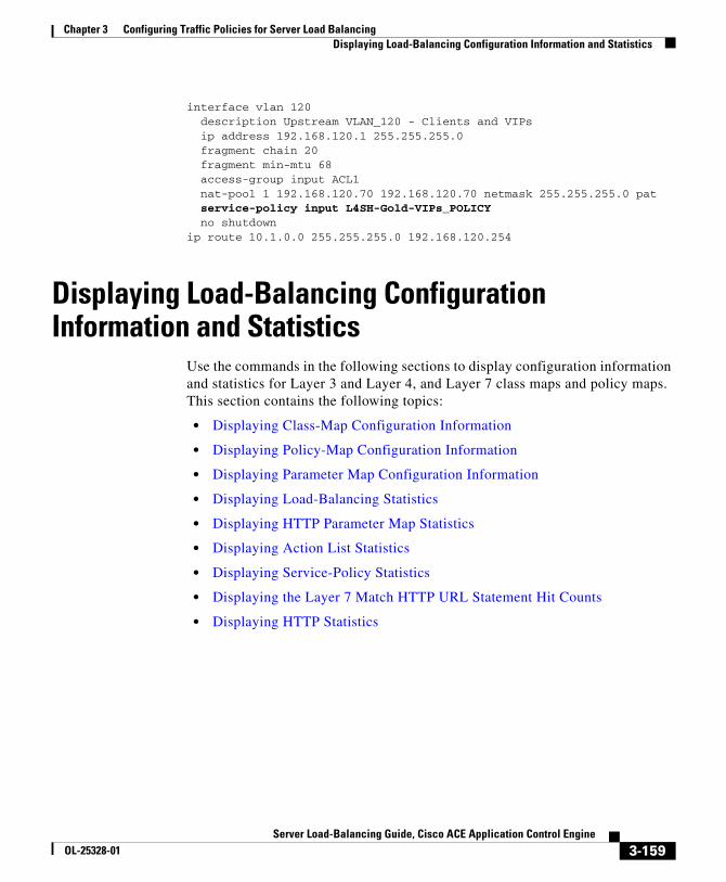
Chapter 3 Configuring Traffic Policies for Server Load BalancingDisplaying Load-Balancing Configuration Information and Statistics
interface vlan 120 description Upstream VLAN_120 - Clients and VIPs ip address 192.168.120.1 255.255.255.0 fragment chain 20 fragment min-mtu 68 access-group input ACL1 nat-pool 1 192.168.120.70 192.168.120.70 netmask 255.255.255.0 pat service-policy input L4SH-Gold-VIPs_POLICY no shutdownip route 10.1.0.0 255.255.255.0 192.168.120.254
Displaying Load-Balancing Configuration Information and Statistics
Use the commands in the following sections to display configuration information and statistics for Layer 3 and Layer 4, and Layer 7 class maps and policy maps. This section contains the following topics:
• Displaying Class-Map Configuration Information
• Displaying Policy-Map Configuration Information
• Displaying Parameter Map Configuration Information
• Displaying Load-Balancing Statistics
• Displaying HTTP Parameter Map Statistics
• Displaying Action List Statistics
• Displaying Service-Policy Statistics
• Displaying the Layer 7 Match HTTP URL Statement Hit Counts
• Displaying HTTP Statistics
3-159Server Load-Balancing Guide, Cisco ACE Application Control Engine
OL-25328-01

Chapter 3 Configuring Traffic Policies for Server Load BalancingDisplaying Load-Balancing Configuration Information and Statistics
Displaying Class-Map Configuration InformationYou can display class-map configuration information by using the show running-config class-map command in Exec mode. This command displays the names of all the class maps configured in the contexts to which you have access and the match statements configured in each class map. The syntax of this command is as follows:
show running-config class-map
Displaying Policy-Map Configuration InformationYou can display policy-map configuration information by using the show running-config policy-map command in Exec mode. This command displays the names of all the policy maps configured in the contexts to which you have access and the class maps and actions configured in each policy map. The syntax of this command is as follows:
show running-config policy-map
Displaying Parameter Map Configuration InformationYou can display a list of parameter maps and their configurations by using the show running-config parameter-map command in Exec mode. The syntax of this command is as follows:
show running-config parameter-map
Displaying Load-Balancing StatisticsYou can display load-balancing statistics by using the show stats loadbalance command in Exec mode. The syntax of this command is as follows:
show stats loadbalance [radius | rdp | rtsp | sip]
3-160Server Load-Balancing Guide, Cisco ACE Application Control Engine
OL-25328-01

Chapter 3 Configuring Traffic Policies for Server Load BalancingDisplaying Load-Balancing Configuration Information and Statistics
The keywords and options are as follows:
• radius—(Optional) Displays Remote Authentication Dial-In User Service (RADIUS) load-balancing statistics associated with the current context.
• rdp—(Optional) Displays Reliable Datagram Protocol (RDP) load-balancing statistics associated with the current context.
• rtsp—(Optional) Displays Real-Time Streaming Protocol (RTSP) load-balancing statistics associated with the current context.
• sip—(Optional) Displays Session Initiation Protocol (SIP) load-balancing statistics associated with the current context.
For example, to see all load-balancing statistics, enter:
host1/Admin# show stats loadbalance
Table 3-10 describes the fields in the show stats loadbalance command output for an HTTP parameter map.
Table 3-10 Field Descriptions for the show stats loadbalance Command
Output
Field Description
Total Version Mismatch
VIP configuration changed during the load-balancing decision and the ACE rejected the connection.
Total Layer4 Decisions
Total number of times that the ACE made a load-balancing decision at Layer 4.
Total Layer4 Rejections
Total number of Layer 4 connections that the ACE rejected.
Total Layer7 Decisions
Total number of times that the ACE made a load-balancing decision at Layer 7.
Total Layer7 Rejections
Total number of Layer 7 connections that the ACE rejected.
Total Layer4 LB Policy Misses
Total number of connection requests that did not match a configured Layer 4 load-balancing policy.
Total Layer7 LB Policy Misses
Total number of connection requests that did not match a configured Layer 7 load-balancing policy.
3-161Server Load-Balancing Guide, Cisco ACE Application Control Engine
OL-25328-01
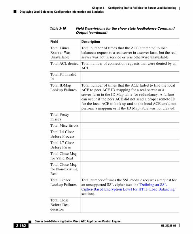
Chapter 3 Configuring Traffic Policies for Server Load BalancingDisplaying Load-Balancing Configuration Information and Statistics
Total Times Rserver Was Unavailable
Total number of times that the ACE attempted to load balance a request to a real server in a server farm, but the real server was not in service or was otherwise unavailable.
Total ACL denied Total number of connection requests that were denied by an ACL.
Total FT Invalid Id
Total IDMap Lookup Failures
Total number of times that the ACE failed to find the local ACE to peer ACE ID mapping for a real-server or a server-farm in the ID Map table for redundancy. A failure can occur if the peer ACE did not send a proper remote ID for the local ACE to look up and so the local ACE could not perform a mapping or if the ID Map table was not created.
Total Proxy misses
Total Misc Errors
Total L4 Close Before Process
Total L7 Close Before Parse
Total Close Msg for Valid Real
Total Close Msg for Non-Existing Real
Total Cipher Lookup Failures
Total number of times the SSL module receives a request for an unsupported SSL cipher (see the“Defining an SSL Cipher-Based Encryption Level for HTTP Load Balancing” section).
Total Close Before Dest decision
Table 3-10 Field Descriptions for the show stats loadbalance Command
Output (continued)
Field Description
3-162Server Load-Balancing Guide, Cisco ACE Application Control Engine
OL-25328-01

Chapter 3 Configuring Traffic Policies for Server Load BalancingDisplaying Load-Balancing Configuration Information and Statistics
Table 3-11 describes the fields in the show stats loadbalance radius command output.
Total Msg sent to Optimization
Total Direct Msg received from Optimization
Total Indirect Msg received from Optimization
Total Optimization Msg sent to Real Servers
Table 3-10 Field Descriptions for the show stats loadbalance Command
Output (continued)
Field Description
Table 3-11 Field Descriptions for the show stats loadbalance radius
Command Output
Field Description
Total Requests Received
Total number of RADIUS client (NAS) requests received
Total Responses Received
Total number of RADIUS server responses received
Total Retry Packets Received
Total number of retransmitted RADIUS requests received
Total Header Parse Results Received
Total number of RADIUS headers parsed and received by the load balance module
Total Body Parse Results Received
Total number of RADIUS attributes parsed and received by the load balance module
3-163Server Load-Balancing Guide, Cisco ACE Application Control Engine
OL-25328-01

Chapter 3 Configuring Traffic Policies for Server Load BalancingDisplaying Load-Balancing Configuration Information and Statistics
Total Data Parse Results Received
Total number of RADIUS packets (requests and responses) parsed and received by the load balance module
Total Packets Sent Out
Total number of RADIUS packets sent out by the ACE on both inbound and outbound interfaces
Total Sessions Allocated
Total number of RADIUS sessions allocated
Total Sessions Deleted
Total number of RADIUS sessions deleted
Total Username Sticky Added
Total number of sticky entries added based on the User-Name attribute
Total Calling-station Sticky Added
Total number of sticky entries added based on the Calling-Station-Id attribute
Total Framed-ip Sticky Added
Total number of sticky entries added based on the Framed-IP-Address attribute
Total End-user Packet Sticky Success
Total number of End-user packets that hit a FIP sticky entry previously created during RADIUS AAA processing
Total End-user Packet Sticky Failure
Total number of End-user packets that failed to hit a FIP sticky entry previously created during RADIUS AAA processing
Total Acct-On/Off Requests Received
Total number of RADIUS Accounting On/Off requests received
Total Acct-On/Off Responses Received
Total number of RADIUS Accounting On/Off responses received
Total Acct-On/Off with No Rules
Total number of RADIUS Accounting On/Off requests for which no valid policy is found
Table 3-11 Field Descriptions for the show stats loadbalance radius
Command Output (continued)
Field Description
3-164Server Load-Balancing Guide, Cisco ACE Application Control Engine
OL-25328-01

Chapter 3 Configuring Traffic Policies for Server Load BalancingDisplaying Load-Balancing Configuration Information and Statistics
Total Acct-On/Off Req Processing Done
Total number of RADIUS Accounting On/Off requests processed successfully by the ACE
Total NULL Packet Received Errors
Total number of invalid (with no data) RADIUS packets received
Total Parse Errors
Total number of RADIUS packets received with no valid RADIUS header
Total invalid proxy mapper entries
Total Sticky Addition Failures
Total number of failures in creating a RADIUS-based sticky entry
Total Proxy Mapper Alloc Failures
Number of proxy mapper entries creation failure. The proxy mapper entry structure maps each inbound connection with multiple outbound connections for point-to-multipoint protocols
Total stale packet errors
Total number of stale RADIUS packets upon receiving a new RADIUS request
Total Radius sessions failures
Total proxy mapper lookup failures
Table 3-11 Field Descriptions for the show stats loadbalance radius
Command Output (continued)
Field Description
3-165Server Load-Balancing Guide, Cisco ACE Application Control Engine
OL-25328-01

Chapter 3 Configuring Traffic Policies for Server Load BalancingDisplaying Load-Balancing Configuration Information and Statistics
Table 3-12 describes the fields in the show stats loadbalance rdp command output.
Table 3-13 describes the fields in the show stats loadbalance rtsp command output.
Table 3-12 Field Descriptions for the show stats loadbalance rdp
Command Output
Field Description
Total Parse Results Received
Total number of RDP parse results received by the load balance module
Total Packets Load Balanced
Total number of RDP packets load balanced
Total Packets with Routing Token
Total number of RDP packets received containing a Routing Token
Total Packets with Token Matching No Rserver
Total number for RDP packets for which the Routing Token does not match any of the configured real servers
Table 3-13 Field Descriptions for the show stats loadbalance rtsp
Command Output
Field Description
Total sessions Allocated
Total number of RTSP sessions allocated
Total Sessions Failed
Total number of RTSP sessions allocation failure
Total Sticky Entries Added
Total number of sticky entries added based on Calling RTSP header
3-166Server Load-Balancing Guide, Cisco ACE Application Control Engine
OL-25328-01

Chapter 3 Configuring Traffic Policies for Server Load BalancingDisplaying Load-Balancing Configuration Information and Statistics
Table 3-14 describes the fields in the show stats loadbalance sip command output.
Displaying HTTP Parameter Map StatisticsYou can display statistics for an HTTP parameter map by using the show parameter-map command in Exec mode. The syntax of this command is as follows:
show parameter-map [name]
The optional name argument is the identifier of an HTTP parameter map. Enter an unquoted text string with a maximum of 64 alphanumeric characters.
For example, to display statistics for the HTTP parameter map called HTTP_PARAMMAP, enter:
host1/Admin# show parameter-map HTTP_PARAMMAP
Table 3-15 describes the fields in the show parameter-map command output for an HTTP parameter map.
Table 3-14 Field Descriptions for the show stats loadbalance sip Command
Output
Field Description
Total sessions Allocated
Total number of SIP sessions allocated
Total Sessions Failed
Total number of SIP sessions that failed
Total sticky entries added
Total number of SIP sticky entries added to the sticky database
Table 3-15 Field Descriptions for the show parameter-map Command
Output
Field Description
Parameter-map Unique identifier of the HTTP parameter map.
Description User-defined text description of the parameter map.
3-167Server Load-Balancing Guide, Cisco ACE Application Control Engine
OL-25328-01

Chapter 3 Configuring Traffic Policies for Server Load BalancingDisplaying Load-Balancing Configuration Information and Statistics
Type HTTP.
Server-side connection reuse
Status of TCP server reuse feature: enabled or disabled.
Case-insensitive parsing
Status of the case-insensitive command: enabled or disabled.
Persistence-rebalance
Status of the persistence-rebalance command: enabled strict, enabled or disabled.
Inspect non-persistence
Status of the inspect non-persistence command: enabled or disabled.
Header modify per-request
Status of the header modify per-request command: enabled or disabled.
Parsing non-strict
Status of the parsing non-strict command: enabled or disabled.
Header-maxparse-length
Configured value or the default value of the header-maxparse-length command.
Content-maxparse-length
Configured value or the default value of the content-maxparse-length command.
Parse length-exceed action
Configured action for the length-exceed command: continue or drop.
Urlcookie-delimiters
Configured URL cookie delimiters.
Urlcookie-start
Displays the start string of the secondary cookie or the none setting configured by the set secondary-cookie-start command in parameter map HTTP configuration mode. The default string of ?.
Table 3-15 Field Descriptions for the show parameter-map Command
Output (continued)
Field Description
3-168Server Load-Balancing Guide, Cisco ACE Application Control Engine
OL-25328-01

Chapter 3 Configuring Traffic Policies for Server Load BalancingDisplaying Load-Balancing Configuration Information and Statistics
Displaying Action List StatisticsYou can display statistics for type modify action lists that you configure in a policy map by using the show action-list command in Exec mode. The syntax of this command is as follows:
show action-list [name]
The optional name argument specifies the name of an existing type modify action list. Enter an unquoted text string with a maximum of 64 alphanumeric characters. If you do not specify the name of an action list, the command displays all action lists configured in the ACE.
For example, to display the HEADER_INSERT action list, enter the following command:
host1/Admin# show action-list HEADER_INSERT
Minimum Size Specifies the threshold at which compression occurs as specified in the HTTP parameter map. The ACE compresses files that are the minimum size or larger. The range is from 1 to 4096 bytes. The default is 512 bytes.
Mimetype Multipurpose Internet Mail Extension (MIME) type to compress as specified in the HTTP parameter map. The default is text/.* which includes all text MIME types, such as text/html, text/plain, and so on.
User-agent Text string in the request to match as specified in the HTTP parameter map. A user agent is a client that initiates a request. Examples of user agents include browsers, editors, or other end user tools. The ACE does not compress the response to a request when the request contains a matching user agent string. The maximum size is 64 characters. The default is none.
Table 3-15 Field Descriptions for the show parameter-map Command
Output (continued)
Field Description
3-169Server Load-Balancing Guide, Cisco ACE Application Control Engine
OL-25328-01

Chapter 3 Configuring Traffic Policies for Server Load BalancingDisplaying Load-Balancing Configuration Information and Statistics
Table 3-15 describes the fields in the show parameter-map command output for an HTTP parameter map.
Table 3-16 Field Descriptions for the show parameter-map Command
Output
Field Description
Action-list Name of the action list.
Description User-defined description of the action list.
Type Kind of action list: modify http.
Header Insert Request
Specifies that the header is to be inserted in the request from the client. Displays the name of the header and the header value.
Header Insert Response
Specifies that the header is to be inserted in the response from the server. Displays the name of the header and the header value.
Header Insert Both Specifies that the header is to be inserted in both the request and the response. Displays the name of the header and the header value.
Header Delete Request
Specifies that the header is to be deleted from the request from the client. Displays the name of the header and the optional header value (if configured).
Header Delete Response
Specifies that the header is to be deleted from the response from the server. Displays the name of the header and the optional header value (if configured).
Header Delete Both Specifies that the header is to be deleted from both the request and the response. Displays the name of the header and the optional header value (if configured).
Header Rewrite Request
Specifies that the header is to be rewritten in the request from the client. Displays the name of the header, the header value, and the replacement string.
Header Rewrite Response
Specifies that the header is to be rewritten in the response from the client. Displays the name of the header, the header value, and the replacement string.
3-170Server Load-Balancing Guide, Cisco ACE Application Control Engine
OL-25328-01

Chapter 3 Configuring Traffic Policies for Server Load BalancingDisplaying Load-Balancing Configuration Information and Statistics
Displaying Service-Policy StatisticsYou can display statistics for service policies enabled globally within a context or on a specific interface by using the show service-policy command. If you do not enter an option with this command, the ACE displays all enabled policy statistics. This command also allows you to display statistics for a specific class map in a policy or a summary of statistics. The syntax of this command is as follows:
show service-policy [policy_name [class-map class_name]] [detail [dad] | summary | url-summary]]
The keywords, arguments, and options are as follows:
• policy_name—(Optional) The name of an existing policy map that is currently in service (applied to an interface). Enter an unquoted text string with no spaces. If you do not enter the name of an existing policy map, the ACE displays information and statistics for all policy maps.
• class-map class_name—(Optional) Displays the statistics for the specified class map associated with the policy.
• detail—(Optional) Displays detailed statistics and status for the policy or class map.
Header Rewrite Both Specifies that the header is to be rewritten in the request and the response. Displays the name of the header, the header value, and the replacement string.
SSL Rewrite Location
Displays the URL string, the SSL port and/or the clear port. For details about SSL URL rewrite, see the SSL Guide, Cisco ACE Application Control Engine.
SSL Header Insert Specifies the SSL header that should be inserted. For details about SSL header insert, see the SSL Guide, Cisco ACE Application Control Engine.
Table 3-16 Field Descriptions for the show parameter-map Command
Output (continued)
Field Description
3-171Server Load-Balancing Guide, Cisco ACE Application Control Engine
OL-25328-01

Chapter 3 Configuring Traffic Policies for Server Load BalancingDisplaying Load-Balancing Configuration Information and Statistics
• dad—(Optional) Displays the operational status of IPv6 VIPs with respect to duplicate address detection (DAD). For details about the output fields of this keyword, see the Routing and Bridging Guide, Cisco ACE Application Control Engine.
• summary—(Optional) Displays a summary of policy or class map statistics and status information in a table format.
• url-summary—(Optional) Displays the number of times that a connection is established (hit count) based on match HTTP URL statements for a class map in a Layer 7 (L7) HTTP policy map. For information on this option and descriptions of the fields, see the “Displaying the Layer 7 Match HTTP URL Statement Hit Counts” section.
Note The ACE updates the counters that the show service-policy command displays after the applicable connections are closed.
For example, to display detailed statistics and current status of the service policy MGMT_POLICYMAP, enter:
host1/Admin# show service-policy MGMT_POLICYMAP detail
Table 3-17 describes the fields in the show service-policy detail command output.
Table 3-17 Field Descriptions for the show service-policy detail Command
Output
Field Description
Policy-map Name of the Layer 4 multimatch policy map.
Status Current operational state of the service policy. Possible states are ACTIVE or INACTIVE.
Description User-entered description of the policy map if any.
Interface VLAN ID of the interface to which the policy map has been applied.
Service Policy Unique identifier of the policy map.
Class Name of the class map associated with the service policy.
VIP Address Virtual IP address specified in the class map.
3-172Server Load-Balancing Guide, Cisco ACE Application Control Engine
OL-25328-01

Chapter 3 Configuring Traffic Policies for Server Load BalancingDisplaying Load-Balancing Configuration Information and Statistics
Protocol Protocol specified in the class map.
Port Port specified in the class map.
VLAN VLAN ID of the interface to which the policy map has been applied.
State Operational state of the VIP. Possible states are:
• IN-SRVC—In service
• OUT-SRVC—Out of service
Loadbalance
L7 Policy Name of the Layer 7 policy map associated with the service policy.
Regex dnld status
Status of the regex download. This field displays the QUEUED, SUCCESSFUL, or FAILED state.
VIP Route Metric
(ACE module only) Specifies the distance metric for the route as specified with the loadbalance vip advertise command. The ACE module writes the value you specify in its routing table. Possible values are integers from 1 to 254.
VIP Route Advertise
(ACE module only) Operational state of the loadbalance vip advertise command: ENABLED or DISABLED. This command is used with route health injection (RHI) to allow the ACE module to advertise the availability of a VIP address throughout the network.
VIP ICMP Reply
Operational state of the loadbalance vip icmp-reply command. Possible states are: ENABLED, DISABLED, ENABLED-WHEN-ACTIVE, or ENABLED-WHEN-PRIMARY-SF-UP.
VIP State Operational state of the virtual server: INSERVICE or OUTOFSERVICE.
Table 3-17 Field Descriptions for the show service-policy detail Command
Output (continued)
Field Description
3-173Server Load-Balancing Guide, Cisco ACE Application Control Engine
OL-25328-01

Chapter 3 Configuring Traffic Policies for Server Load BalancingDisplaying Load-Balancing Configuration Information and Statistics
VIP DWS state
The DWS state of the VIP. Possible states are: DWS_ENABLED or DWS_DISABLED.
VIP Dad state
Final DAD status when there are multiple VIPs.
Persistence Rebalance
Operational state of the persistence-rebalance command. Possible states are: ENABLED, DISABLED, or STRICT.
Curr Conns Number of active connections to the VIP.
Hit Count Number of times a connection was established with this VIP.
Dropped Conns
Number of connections that the ACE discarded.
Client Pkt Count
Number of packets received from the client.
Client Byte Count
Number of bytes received from the client.
Server Pkt Count
Number of packets received from the server.
Server Byte Count
Number of bytes received from the server.
Max-conn-limit
Configured value of the conn-limit max command. See Chapter 2, Configuring Real Servers and Server Farms.
Drop-count Number of connections that were dropped because the maximum connection limit was exceeded.
Conn-rate-limit
Configured value of the rate-limit connection command. See Chapter 2, Configuring Real Servers and Server Farms.
Drop-count Number of connections that were dropped because the connection rate limit was exceeded.
bandwidth-rate-limit
Configured value of the rate-limit bandwidth command. See Chapter 2, Configuring Real Servers and Server Farms.
Drop-count Number of connections that were dropped because the bandwidth rate limit was exceeded.
Table 3-17 Field Descriptions for the show service-policy detail Command
Output (continued)
Field Description
3-174Server Load-Balancing Guide, Cisco ACE Application Control Engine
OL-25328-01

Chapter 3 Configuring Traffic Policies for Server Load BalancingDisplaying Load-Balancing Configuration Information and Statistics
Compression
bytes_in Number of bytes of data in the server response that was eligible for compression by the ACE.
bytes_out Number of compressed bytes of data sent to the client by the ACE.
Compression ratio
Between the byte count of the traffic that was sent to the ACE for compression and that traffic’s byte count after the ACE performed the compression. This value indicates how well the ACE applied the compression algorithm.
Bandwidth gain ratio
Ratio of bytes_in/bytes_out expressed as a percentage. This value indicates how compression influences the overall bandwidth because it also takes into consideration the traffic that is not being compressed.
Gzip Number of gzip requests from the client.
Deflate Number of deflate requests from the client.
User-Agent Number of times that compression did not occur because of a user-agent match.
Accept-Encoding
Number of times that compression did not occur because of an Accept-Encoding error.
Content size Number of times that compression did not occur because of a response size error. This error occurs when the content size of a packet is less than what the ACE can compress. The minimum and default content size is 512 bytes.
Content type Number of times that compression did not occur because of a response content error. This error occurs when the packet contains a content type that the ACE does not compress.
Not HTTP 1.1
Number of times that compression did not occur because the HTTP version is not 1.1.
HTTP response error
Number of times that compression did not occur because of a server response error. This error occurs when the server response is not 200 OK.
Table 3-17 Field Descriptions for the show service-policy detail Command
Output (continued)
Field Description
3-175Server Load-Balancing Guide, Cisco ACE Application Control Engine
OL-25328-01

Chapter 3 Configuring Traffic Policies for Server Load BalancingDisplaying Load-Balancing Configuration Information and Statistics
Others Reserved for future use.
L4 Policy Stats
Total Req/Resp
Total number of requests and responses for the policy map.
Total Allowed
Total number of packets received and allowed.
Total Dropped
Total number of packets received and discarded.
Total Logged Total number of errors logged.
L7 loadbalance policy
Identifier of the Layer 7 policy map.
Class-map Identifier of the associated class map.
LB action Actions specified within the Layer 7 policy map as follows:
• Sticky group—Name of the sticky group associated with this policy.
• Primary server farm—identifier of the primary server farm
• State—Current state of the primary server farm: UP or DOWN
• Backup server farm—Identifier of the backup server farm
• State—Current state of the primary server farm: UP or DOWN
Hit Count Cumulative number of connections to the primary or backup server farm.
Dropped Conns
Number of attempted connections to the primary or backup server farm that the ACE discarded.
Table 3-17 Field Descriptions for the show service-policy detail Command
Output (continued)
Field Description
3-176Server Load-Balancing Guide, Cisco ACE Application Control Engine
OL-25328-01

Chapter 3 Configuring Traffic Policies for Server Load BalancingDisplaying Load-Balancing Configuration Information and Statistics
Displaying the Layer 7 Match HTTP URL Statement Hit CountsYou can display the number of times that a connection is established (hit count) based on match HTTP URL statements for a class map in a Layer 7 (L7) HTTP policy map by using the show service-policy url-summary command. If you do not enter a policy map name with this command, the ACE displays the match URL statement hit counts for all class maps in L7 HTTP policy maps.
The syntax of this command is as follows:
show service-policy [policy_name [class-map class_name]] url-summary
The options are as follows:
• policy_name—(Optional) Name of an existing Layer 3 and Layer 4 HTTP policy map. Enter an unquoted text string with no spaces. If you do not enter a policy map name with this command, the ACE displays the match URL statement hit counts for all class maps in L7 HTTP policy maps.
• class-map class_name—(Optional) Displays the statement hit counts for the specified class map associated with the policy. Enter the name as an unquoted text string with no spaces.
For example, to display the hit count for the match HTTP URL statements for all class maps in all policy maps, enter the following command:
host1/Admin# show service-policy url-summary
Hit count Number of times a connection was established with this policy.
Dropped conns Number of connections associated with this policy that were dropped.
Table 3-17 Field Descriptions for the show service-policy detail Command
Output (continued)
Field Description
3-177Server Load-Balancing Guide, Cisco ACE Application Control Engine
OL-25328-01

Chapter 3 Configuring Traffic Policies for Server Load BalancingDisplaying Load-Balancing Configuration Information and Statistics
Table 3-18 describes the fields in the show service-policy url-summary command output.
Displaying HTTP StatisticsYou can display HTTP statistics, including header insertion and server reuse statistics by using the show stats http command in Exec mode. The syntax of this command is as follows:
show stats http
Table 3-18 Field Descriptions for the show service-policy url-summary
Command Output
Field Description
Service Policy Unique identifier of the policy map.
L3-Class Name of the Layer 3 class map associated with the service policy.
L7-Class Identifier of the Layer 7 class map.
match http url The HTTP URL match statement.
hit The number of times that a connection is established based on a specific URL match statement.
Note The URL hit counter is incremented per URL match statement per load-balancing Layer 7 policy. However, if you associate the same combination of Layer 7 policy map and class map with a URL match statement with different VIPs, the counter is incremented and displayed for all VIPs associated with the Layer 7 policy. If the ACE configuration exceeds 64K URL and load-balancing policy combinations, this counter displays NA.
3-178Server Load-Balancing Guide, Cisco ACE Application Control Engine
OL-25328-01

Chapter 3 Configuring Traffic Policies for Server Load BalancingDisplaying Load-Balancing Configuration Information and Statistics
Table 3-19 describes the fields in the show stats http command output.
Table 3-19 Field Descriptions of the show stats http Output
Field Description
LB parse result msgs sent The HTTP module generated a parse result for a load-balancing decision (header, cookie, or URL string), and sent the results to the LoadBalance application to use in the (Layer 7) load-balancing decision. Layer 7 load-balancing match classes are configured using the class-map type http loadbalance match-any | match-all class_name and match http. . . commands, which are used to define a Layer 7 load-balancing policy.
TCP data msgs sent While parsing data, the HTTP module needed to send either parsed data for forwarding or TCP flags to the TCP module to keep the TCP connection going. This is normal.
Inspect parse result msgs sent
The HTTP module has completed parsing for an HTTP inspection rule and sent the results to the HTTP inspection application to be either logged, permitted, or reset. Layer 7 inspection match classes are configured using the class-map type http inspect match-all | match-any class_name and match header | url | content. . . commands, which are used to define a Layer 7 HTTP inspection policy.
SSL data msgs sent While parsing data, the HTTP module needed to send either parsed data for forwarding to the SSL module to keep the connection going. This is normal.
TCP fin msgs sent If the HTTP module on the ACE detects a condition under which the TCP connection must be closed, the ACE sends a FIN message and increments this counter. These can be normal.
TCP rst msgs sent If the HTTP module on the ACE detects a condition under which the TCP connection must reset, the ACE sends messages are sent and logged here. These can be normal.
3-179Server Load-Balancing Guide, Cisco ACE Application Control Engine
OL-25328-01

Chapter 3 Configuring Traffic Policies for Server Load BalancingDisplaying Load-Balancing Configuration Information and Statistics
Bounce fin msgs sent If the HTTP module receives a FIN indication in the TCP connection prior to starting the parsing of an HTTP request and no other-side connection has been opened to the ultimate receiver of the request, then the ACE sends the FIN message to the sender, and closes the existing connection. An example of this (although not the only possible one) is a client who sends SYN, SYN/ACK, or FIN to the ACE.
Bounce rst msgs sent If the HTTP module receives a RST indication in the TCP connection prior to starting the parsing of an HTTP request and no other-side connection has been opened to the ultimate receiver of the request, then the ACE sends the RST message to the sender, and closes the existing connection. An example of this (although not the only possible one) is a client who sends SYN, SYN/ACK, or RST to the ACE.
SSL fin msgs sent If the HTTP module detects a condition under which the TCP connection must be closed, the ACE sends a FIN message and increments this counter. These can be normal.
SSL rst msgs sent If the HTTP module detects a condition under which the TCP connection must be reset, the ACE sends a RST message and increments this counter. These messages can be normal.
Drain msgs sent A response has been received and completed for an HTTP request. Whenever the persistence-rebalance command or the server-conn reuse command is enabled, the ACE sends a drain message at the end of the response. This message is sent because there's no way to tell without checking whether there is a pipelined request waiting to be parsed.
Particles read For internal use only.
Table 3-19 Field Descriptions of the show stats http Output (continued)
Field Description
3-180Server Load-Balancing Guide, Cisco ACE Application Control Engine
OL-25328-01

Chapter 3 Configuring Traffic Policies for Server Load BalancingDisplaying Load-Balancing Configuration Information and Statistics
Reuse msgs sent Number of times the HTTP process requested that a connection be placed in the reuse pool. This counter increments every time a server-conn reuse connection is freed and HTTP requests that it be returned to the pool.
HTTP requests Total HTTP requests received by the HTTP module for parsing, either pipelined or not. This counter tracks only those HTTP requests that the HTTP module actually receives. If a connection is configured using the persistence-rebalance command, this count includes all HTTP requests received on that connection because each one must be parsed. Connections configured for the server-conn reuse command also require parsing of every HTTP request because a server-side connection can only be reused after it has transmitted the last byte of the response. Parsing of the response, and hence also of the request, must be done to make this determination. However, if neither the persistence-rebalance command nor the server-conn reuse command is configured, then only the first HTTP request on a connection requires parsing. This count may also include non-HTTP requests (for example, SIP, Skinny, RADIUS, generic TCP or UDP) that flow through the HTTP module.
Table 3-19 Field Descriptions of the show stats http Output (continued)
Field Description
3-181Server Load-Balancing Guide, Cisco ACE Application Control Engine
OL-25328-01

Chapter 3 Configuring Traffic Policies for Server Load BalancingDisplaying Load-Balancing Configuration Information and Statistics
Reproxied requests HTTP requests that must be parsed and are received on a connection that has previously been unproxied require that the connection be reproxied. For example, when the persistence-rebalance command is configured, the connections can be reproxied because a second request on an already unproxied connection requires parsing by HTTP to see if the connection should be rebalanced. Reproxying also occurs when the server-conn reuse command is configured. Each request is parsed and the response must be parsed also to know when the server-side connection can be returned to the reuse pool.
Headers removed HTTP headers that are removed by the HTTP module from requests or responses. Removal of user-specified header names is also supported.
Headers inserted HTTP headers inserted into the HTTP request or response by the HTTP module. This includes both the Connection: Keep-Alive header for a request that is sent to the server over connections configured with the server-conn reuse command and a header that is inserted using the header insert feature.
HTTP redirects Number of times that the HTTP module formed a response for a redirect server farm and sent it back to the client.
HTTP chunks Chunks of HTTP data received by the HTTP module related to chunked encoding.
Pipelined requests A valid subsequent HTTP request arrives prior to the arrival of the response to the previous HTTP request. For example, a second GET may arrive from the client before the 200 OK response to the first one is received. Parsing of the second request in the pipeline is deferred until the response to the first request has been received and processed.
Table 3-19 Field Descriptions of the show stats http Output (continued)
Field Description
3-182Server Load-Balancing Guide, Cisco ACE Application Control Engine
OL-25328-01

Chapter 3 Configuring Traffic Policies for Server Load BalancingDisplaying Load-Balancing Configuration Information and Statistics
HTTP unproxy conns Requests by the HTTP module to unproxy a connection was successfully completed.
Pipeline flushes Pipelined data (as opposed to a single HTTP request) is sent (flushed) to the TCP module or the SSL module if the server closes the connection prematurely using a FIN or a RST. In this case, all the pipelined data is sent, rather than waiting for each HTTP response in an orderly fashion and parsing the pipelined requests.
Whitespace appends Number of pipelined requests that are not actual HTTP requests, but are (legal, no-op) white space.
Second pass parsing The HTTP module may need to parse twice, once for load balancing and again for HTTP inspection. This counter indicates a second pass of parsing on the same HTTP request or response.
Response entries recycled
Received HTTP responses that are reused to send HTTP requests. This counter appears to be a reasonable approximation of HTTP requests that are sent over existing connections for the server-conn reuse command. Note, though, that this counter is not specific to the server-conn reuse command because, when reuse is disabled, persistent connections may also send multiple requests over the same backend connection when the same real server is chosen on subsequent requests. If an unproxy occurs between requests, this counter does not increment.
Analysis errors Errors in the HTTP parser.
Header insert errors Number of times that an HTTP header could not be inserted. If this counter increases in lockstep with the Resource errors field, the failure may be due to a problem in getting resources, but this is not always the case.
Table 3-19 Field Descriptions of the show stats http Output (continued)
Field Description
3-183Server Load-Balancing Guide, Cisco ACE Application Control Engine
OL-25328-01

Chapter 3 Configuring Traffic Policies for Server Load BalancingDisplaying Load-Balancing Configuration Information and Statistics
Max parselen errors The HTTP module reached the end of the configured maximum parse length without finding a match for the desired regular expression. The connection is not necessarily reset as a result of this error.
Static parse errors Either the client or the server data that was parsed by the HTTP module did not conform to the correct HTTP format and the parsing was aborted.
Resource errors A buffer or other internal resource that is required by the HTTP module was unexpectedly not available.
Invalid path errors This counter may increment as a result of a race condition during processing. The path is the path the buffer takes within the ACE.
Bad HTTP version errors Only HTTP version 1.x is expected. Other versions cause this counter to increment.
Headers rewritten HTTP headers that are modified by the HTTP module from requests or responses. The HTTP module modifies headers according to the user-specified http modify action-list.
Header rewrite errors Number of times that an HTTP header could not be rewritten. If this counter increases in lockstep with the Resource errors field, the failure may be due to a problem in getting resources, but this is not always the case.
Unproxy msgs sent Requests by the HTTP module that a connection be unproxied. An unproxy request is sent when the HTTP response header is complete (ending the completed request or response transaction) or when the response data in its entirety ends, for chunked encoding. If there is a pipelined request when the response is completed, the connection cannot unproxy. In this case, this counter will still increment, but the unproxy will later be canceled. Note that unproxy is never attempted for SSL traffic.
HTTP passthrough stat
Table 3-19 Field Descriptions of the show stats http Output (continued)
Field Description
3-184Server Load-Balancing Guide, Cisco ACE Application Control Engine
OL-25328-01

Chapter 3 Configuring Traffic Policies for Server Load BalancingClearing SLB Statistics
Clearing SLB StatisticsThis section describes the commands that you can use to clear load-balancing statistics. It includes the following topics:
• Clearing Load-Balancing Statistics
• Clearing Service-Policy Statistics
• Clearing HTTP Statistics
Clearing Load-Balancing StatisticsYou can clear all load-balancing statistics in the current context by using the clear stats loadbalance command in Exec mode. The syntax of this command is as follows:
clear stats loadbalance [radius | rdp | rtsp | sip]
The keywords and options are as follows:
• radius—(Optional) Clears Remote Authentication Dial-In User Service (RADIUS) load-balancing statistical information.
• rdp—(Optional) Clears Reliable Datagram Protocol (RDP) load-balancing statistical information.
• rtsp—(Optional) Clears Real-Time Streaming Protocol (RTSP) load-balancing statistical information.
• sip—(Optional) Clears Session Initiation Protocol (SIP) load-balancing statistical information.
For example, enter:
host1/Admin# clear stats loadbalance
Note If you have redundancy configured, you need to explicitly clear load-balancing statistics on both the active and the standby ACEs. Clearing statistics on the active ACE only leaves the standby ACE’s statistics at the old values.
3-185Server Load-Balancing Guide, Cisco ACE Application Control Engine
OL-25328-01

Chapter 3 Configuring Traffic Policies for Server Load BalancingClearing SLB Statistics
Clearing Service-Policy StatisticsYou can clear service policy statistics by using the clear service-policy command. The syntax of this command is as follows:
clear service-policy policy_name
For the policy_name argument, enter the identifier of an existing policy map that is currently in service (applied to an interface).
For example, to clear the statistics for the policy map L4SLBPOLICY that is currently in service, enter:
host1/Admin# clear service-policy L4SLBPOLICY
Note If you have redundancy configured, you need to explicitly clear service-policy statistics on both the active and the standby ACEs. Clearing statistics on the active ACE only leaves the standby ACE’s statistics at the old values.
Clearing HTTP StatisticsYou can clear all HTTP statistics in the current context by using the clear stats http command in Exec mode. The syntax of this command is as follows:
clear stats http
For example, enter:
host1/Admin# clear stats http
Note If you have redundancy configured, you need to explicitly clear HTTP statistics on both the active and the standby ACEs. Clearing statistics on the active ACE only leaves the standby ACE’s statistics at the old values.
3-186Server Load-Balancing Guide, Cisco ACE Application Control Engine
OL-25328-01

Chapter 3 Configuring Traffic Policies for Server Load BalancingWhere to Go Next
Where to Go NextTo configure health probes for your real servers, go to Chapter 4, Configuring Health Monitoring. To configure stickiness (connection persistence), see Chapter 5, Configuring Stickiness. To configure firewall load balancing (FWLB), see Chapter 6, Configuring Firewall Load Balancing.
3-187Server Load-Balancing Guide, Cisco ACE Application Control Engine
OL-25328-01
Chapter 3 Configuring Traffic Policies for Server Load BalancingWhere to Go Next
3-188Server Load-Balancing Guide, Cisco ACE Application Control Engine
OL-25328-01