configuring pipes 2 3 comos p&id administration …...comos process p&id administration...
TRANSCRIPT

COMOS
ProcessP&ID Administration
Operating Manual
09/2014A5E32035649-AC
Unit structures 1
Configuring pipes 2
Configuring P&IDs 3
Configuring components 4
Copying/cutting and pasting 5Changing color settings globally 6
Configuring the interfaces 7Assigning a process coupling to functions 8Increasing the processing speed 9
Base data reference 10Script functions in the options script for P&ID 11
User interface reference 12
Legal informationWarning notice system
This manual contains notices you have to observe in order to ensure your personal safety, as well as to prevent damage to property. The notices referring to your personal safety are highlighted in the manual by a safety alert symbol, notices referring only to property damage have no safety alert symbol. These notices shown below are graded according to the degree of danger.
DANGERindicates that death or severe personal injury will result if proper precautions are not taken.
WARNINGindicates that death or severe personal injury may result if proper precautions are not taken.
CAUTIONindicates that minor personal injury can result if proper precautions are not taken.
NOTICEindicates that property damage can result if proper precautions are not taken.If more than one degree of danger is present, the warning notice representing the highest degree of danger will be used. A notice warning of injury to persons with a safety alert symbol may also include a warning relating to property damage.
Qualified PersonnelThe product/system described in this documentation may be operated only by personnel qualified for the specific task in accordance with the relevant documentation, in particular its warning notices and safety instructions. Qualified personnel are those who, based on their training and experience, are capable of identifying risks and avoiding potential hazards when working with these products/systems.
Proper use of Siemens productsNote the following:
WARNINGSiemens products may only be used for the applications described in the catalog and in the relevant technical documentation. If products and components from other manufacturers are used, these must be recommended or approved by Siemens. Proper transport, storage, installation, assembly, commissioning, operation and maintenance are required to ensure that the products operate safely and without any problems. The permissible ambient conditions must be complied with. The information in the relevant documentation must be observed.
TrademarksAll names identified by ® are registered trademarks of Siemens AG. The remaining trademarks in this publication may be trademarks whose use by third parties for their own purposes could violate the rights of the owner.
Disclaimer of LiabilityWe have reviewed the contents of this publication to ensure consistency with the hardware and software described. Since variance cannot be precluded entirely, we cannot guarantee full consistency. However, the information in this publication is reviewed regularly and any necessary corrections are included in subsequent editions.
Siemens AGIndustry SectorPostfach 48 4890026 NÜRNBERGGERMANY
A5E32035649-ACⓅ 09/2014 Subject to change
Copyright © Siemens AG 2014.All rights reserved

Table of contents
1 Unit structures..............................................................................................................................................7
1.1 Offered unit structures..............................................................................................................7
1.2 Unit structures according to standard......................................................................................7
2 Configuring pipes..........................................................................................................................................9
2.1 Pipe structures.........................................................................................................................92.1.1 Preparing a base object of the pipe object...............................................................................92.1.2 Preparing a base object of the pipe section...........................................................................102.1.3 Preparing a base object of the pipe segment.........................................................................112.1.4 Specifying references in the project properties......................................................................12
2.2 Enabling selection of a standard pipe....................................................................................12
2.3 Data flow for pipes via static connections..............................................................................132.3.1 Introduction............................................................................................................................132.3.2 Special consideration when calling the "UpdateConnected" function....................................132.3.3 Data flow in detail...................................................................................................................142.3.4 Configuration..........................................................................................................................152.3.4.1 Enabling data flow..................................................................................................................152.3.4.2 Configuring the "By connector" attribute link..........................................................................152.3.4.3 Configuring how attribute families are handled......................................................................162.3.4.4 Calling UpdateConnected......................................................................................................182.3.4.5 Script call................................................................................................................................18
2.4 Graphic properties..................................................................................................................192.4.1 Apply graphical properties of a pipe.......................................................................................192.4.2 Enabling the user to set the graphical properties of pipe segments......................................19
2.5 Applying properties of pipes to branches...............................................................................20
2.6 Pipe overlaps on the P&ID.....................................................................................................202.6.1 Display types..........................................................................................................................202.6.2 Customizing pipe priorities.....................................................................................................22
2.7 Deleting pipes automatically..................................................................................................23
2.8 Configuring automatic assignment of line types.....................................................................242.8.1 Overview of automatic assignment of line types....................................................................242.8.2 Specifying component types to be used................................................................................242.8.3 Specifying line types..............................................................................................................242.8.4 Adding the "Line type class" attribute to the attributes of the base objects............................25
2.9 Automatically placing T-pieces...............................................................................................26
2.10 Connector symbol for pipe spec-relevant information............................................................27
3 Configuring P&IDs......................................................................................................................................29
3.1 Properties of the P&ID...........................................................................................................29
3.2 Configuring report templates..................................................................................................31
P&ID AdministrationOperating Manual, 09/2014, A5E32035649-AC 3

3.2.1 Editing properties...................................................................................................................313.2.1.1 Defining the base object for pipe sections.............................................................................323.2.2 Automatically sorting objects into categories when placing them on the P&ID......................323.2.3 Extending the graphical settings............................................................................................333.2.4 Locking editable text against editing......................................................................................33
3.3 Symbols.................................................................................................................................343.3.1 Setting the size of connectors for P&ID objects.....................................................................343.3.2 Standard pipe labels..............................................................................................................343.3.3 End symbols...........................................................................................................................35
3.4 Displaying coordinates of components..................................................................................363.4.1 Quadrants/page areas...........................................................................................................363.4.2 Creating zones.......................................................................................................................363.4.3 Displaying coordinates of page references............................................................................363.4.4 Symbol script for page references (input)..............................................................................37
3.5 Search functions for P&ID......................................................................................................383.5.1 GetDeviceConnectedToPipe..................................................................................................383.5.2 GetConnectorOfDeviceConnectedToPipe.............................................................................393.5.3 Search modes........................................................................................................................39
3.6 Mounting a rotation correction for PFD symbols....................................................................42
3.7 Mounting a scaling correction for PFD/P&ID symbols...........................................................43
4 Configuring components.............................................................................................................................45
4.1 Global preset of component refreshing..................................................................................45
4.2 Disabling automatic classification of components..................................................................45
4.3 Changing the behavior of the flow direction...........................................................................46
4.4 Determining the flow direction with multiway objects.............................................................47
4.5 Forcing action lines................................................................................................................47
5 Copying/cutting and pasting.......................................................................................................................49
5.1 Overview of copying/cutting and pasting................................................................................49
5.2 Dependencies when copying and pasting objects.................................................................50
5.3 Examples of copying and pasting..........................................................................................52
5.4 Dependencies when cutting and pasting objects...................................................................54
5.5 Examples of cutting and pasting............................................................................................54
5.6 Enabling copying if the hierarchical structure up to a position...............................................56
6 Changing color settings globally.................................................................................................................59
6.1 Overview................................................................................................................................59
6.2 Queries...................................................................................................................................59
6.3 Assigning colors.....................................................................................................................60
6.4 Enabling color settings via the context menu.........................................................................60
7 Configuring the interfaces...........................................................................................................................61
7.1 Configuring XMpLant export..................................................................................................61
Table of contents
P&ID Administration4 Operating Manual, 09/2014, A5E32035649-AC

7.1.1 Administration of the "XMpLant" tab......................................................................................617.1.2 Hard-coded PlantItem types...................................................................................................62
7.2 Configuring XMpLant export..................................................................................................637.2.1 Creating "OnXMpLantImportDone" at COMOS objects.........................................................63
7.3 Configuration file for the DGN import.....................................................................................647.3.1 Configuration file "DGNImport1.xml"......................................................................................647.3.2 Assigning a DGN line type to a COMOS line type.................................................................647.3.3 Assigning a DGN layer to a COMOS layer............................................................................657.3.4 Assigning a DGN font to a Windows font...............................................................................667.3.5 Undoing an assignment.........................................................................................................67
7.4 Pipe Easy...............................................................................................................................677.4.1 Adding the "Show PipeEasy conversion settings" button to the toolbar................................677.4.2 Configuring tabs of the "Conversion settings" window...........................................................687.4.3 Creating base objects for text rules........................................................................................68
7.5 PDF import.............................................................................................................................707.5.1 Rules for creating the PDF import..........................................................................................707.5.1.1 Introduction............................................................................................................................707.5.1.2 Creating rule sets...................................................................................................................717.5.1.3 Creating a rule........................................................................................................................71
8 Assigning a process coupling to functions..................................................................................................73
9 Increasing the processing speed................................................................................................................75
10 Base data reference...................................................................................................................................77
10.1 Base object "@10 > A20 > A10 P&ID"...................................................................................77
10.2 Base object "@20 > A80 > M22 > A10 Script library M22S00001 - M22S00050".................77
10.3 Base object "@10 > A20 > A10 > A10 Physical objects".......................................................7710.3.1 Labeling..................................................................................................................................7710.3.2 Symbol...................................................................................................................................7810.3.3 Attributes, general..................................................................................................................8010.3.4 "System data" tab...................................................................................................................80
10.4 Base object "@10 > A20 > A10 > A10 > A60 Elements and components"............................8110.4.1 Base object "@10 > A20 > A10 > A10 > A60 > A20 Nozzles and connections"....................81
10.5 Base object "@30 > M00 > A50 > A10 > A80 Add. graphics and symbol drawing"...............8210.5.1 Base object "@30 > M00 > A50 > A10 > A80 > A10 Text symbols P&ID"............................8210.5.2 Base object "@30 > M00 > A50 > A10 > A80 > A30 Graphical symbols P&ID"....................83
10.6 Base object "@30 > M00 > A80 > A10 Document library objects acc. to IEC 61355"...........85
10.7 Structure of the base objects of functions..............................................................................8510.7.1 Base object "@20 > A30 > A10 > A10 General functions"....................................................8510.7.2 Base object "@20 > A30 > A10 > A20 Measurement function" and "@20 > A30 > A10
> A30 Actuating function".......................................................................................................8610.7.3 Scripts....................................................................................................................................86
10.8 Base object "@30 > M00 > A50 > A10 > A10 > A10 Vessels and tanks"..............................89
10.9 Base object "@30 > M00 > A50 > A10 > A30 Valves"...........................................................89
10.10 Standard tables......................................................................................................................89
Table of contents
P&ID AdministrationOperating Manual, 09/2014, A5E32035649-AC 5

10.11 Object classes of P&ID objects..............................................................................................91
11 Script functions in the options script for P&ID............................................................................................93
11.1 AutoConnectGrayboxes.........................................................................................................93
11.2 AutoPlaceTPiece (Integer).....................................................................................................93
11.3 AllowPrintingForDirectionArrow (Boolean).............................................................................93
11.4 CheckAllOpenFunctionConns (Boolean)...............................................................................93
11.5 CheckAllOpenPipeConns (Boolean)......................................................................................94
11.6 CObjectFullNameForPipe (String).........................................................................................94
11.7 ConnectorRadius (Double).....................................................................................................94
11.8 CopyMainBranch (String).......................................................................................................94
11.9 CopyPipeConnectionAutoOff.................................................................................................95
11.10 CreateDefaultPipeSegment (Boolean)...................................................................................95
11.11 DrawPFDConnsUnderDocumentInBlue (Boolean)................................................................96
11.12 DrawPFDDevicesUnderDocumentInBlue (Boolean)..............................................................96
11.13 DrawPipeEndSymbol (Boolean).............................................................................................96
11.14 DrawPipeEndSymbolForSegment (Boolean).........................................................................97
11.15 DrawPipeConnectorSymbol (Boolean)..................................................................................97
11.16 DrawPipeEndSymbolForVertices (Boolean)..........................................................................97
11.17 EnableContinueDrawingConnection......................................................................................98
11.18 EnableInteractiveEditableTexts..............................................................................................98
11.19 SetImplementationByConcessionRI (Boolean)......................................................................99
11.20 SetPipeFlagOnCreate (Boolean)...........................................................................................99
11.21 SortNewBranchUnderNewPipe (Boolean).............................................................................99
11.22 StdPipeFlagNoColor (Boolean)............................................................................................100
11.23 StdPipeNoReflect (Boolean)................................................................................................100
11.24 SynchronizePipeConSymbol (Boolean)...............................................................................100
11.25 SynchronizeStdPipeFlag (Boolean).....................................................................................100
12 User interface reference...........................................................................................................................101
12.1 String rule manager..............................................................................................................101
Table of contents
P&ID Administration6 Operating Manual, 09/2014, A5E32035649-AC

Unit structures 11.1 Offered unit structures
The unit structures that can are offered in the context menu when the "New" command is selected depend on the project structure that was selected in the properties of an engineering project. Category "General settings > Project", "Project structure" field
The unit structures are located in the base data under the base object node "@30 > M00 > A30 Units".
The structures according to EN follow the usual engineering structures of the chemical industry.
1.2 Unit structures according to standard
Structure according to ENP&IDs are prepared for engineering within the unit structure. The unit structure according to EN has an identical design, apart from a few P&IDs.
● "@30 > M00 > A30 > A20 > A10 > A10 > A10 Plant"
● "@30 > M00 > A30 > A20 > A10 > A20 > A10 Unit":P&IDs can be created in the structures below the main unit.
● "@30 > M00 > A30 > A20 > A10 > A30 > A10 Subunit":
– P&IDs are created below the subunit.
– A number of category folders are created automatically below the subunit when a subunit is created.The Technique category creates a clearer structure for the engineering objects, for example, by automatically collecting all pipes placed on a P&ID in one folder. You can find additional information on this topic in the "P&ID Operation" manual, keyword"Categories".You do not usually need the "I&C (instrumentation & control)" folder until I&C engineering. The positions are created below it, and the functions are created below. It is sufficient for P&ID engineers to place functions on a P&ID. You can find more information on this topic in the "EI&C Operation" manual, keyword "Positions".
P&ID AdministrationOperating Manual, 09/2014, A5E32035649-AC 7

Unit structures1.2 Unit structures according to standard
P&ID Administration8 Operating Manual, 09/2014, A5E32035649-AC
Configuring pipes 22.1 Pipe structures
Depending on the drawing type of the P&ID, a three-level pipe structure or a two-level pipe structure is created when a user draws a pipe.
You can find more information on this topic in the "P&ID Operation" manual, keyword "Pipe structures".
To construct the pipe structure, first prepare the base objects, which will be used in the pipe structure, and set the base object for pipe sections in the project properties.
2.1.1 Preparing a base object of the pipe object
Procedure1. Open the base object properties of a pipe.
Path in the database: "@10 > A20 > A10 > A10 > A40 > A10 > A10 Pipe.
2. Make the following settings:
– "Class" = "Position"
– "Subclass" = "None"
– "Creation option" = "Normal"
– "Creation mode" = "Free"
3. Open the base object properties of a pipe.Path in the database: "@30 > M00 > A50 > A10 > A40 > A10 > A10 Pipe"
4. Open the "System" tab.
5. Open the "Elements" tab.
6. Prepare a pipe section as an element.
7. Optional: Prepare additional elements.
You can find more information on this topic in the "COMOS Platform Administration" manual, keyword "Creating elements at base objects".
P&ID AdministrationOperating Manual, 09/2014, A5E32035649-AC 9
2.1.2 Preparing a base object of the pipe section
RequirementYou have defined a pipe section as an element of a pipe in the base data. See also chapter Preparing a base object of the pipe object (Page 9).
Procedure1. Open the base object properties of the pipe section in the "@10" node.
Path in the database: "@10 > A20 > A10 > A10 > A40 > A10 > A20 Pipe section"
2. Open the "System" tab.
3. Make the following settings:
– "Class": "Position"
– "Subclass": "Pipe"
– "Creation option": "Normal"
– "Creation mode": "Free"
4. Open the "Connectors" tab.
5. Create an input "DI1" and an output "DO1" of the type P&ID. The connectors must be named "DI1" and "DO1".
6. Open the properties of the pipe section in node "@30" which you created as element of the pipe.Path in the database: "@30 > M00 > A50 > A10 > A40 > A10 > A10 > A10 Pipe section"
7. Open the "Elements" tab.
8. Create a pipe segment named "SEG" as element. Path in the database: "@30 > M00 > A50 > A10 > A40 > A10 > SEG Pipe segment"You can find additional information on this topic in the "COMOS Platform Administration" manual, keyword "Adding elements".
Result● If the user places a component with the attribute "Pipe cut mode" = "Segment separative"
on the pipe section, new pipe segments are created below the pipe section based on this element. The branches are created below the pipe section and joined to the fitting by means of their connectors.If a pipe section is place on a P&ID, a pipe segment is created automatically below this pipe section.
● If the user works in a P&ID with "M22_P1" drawing type, an engineering object of this pipe section is created automatically below the pipe object when the pipe is drawn.
Sorting pipe sections automatically below objectsIf the user places a pipe section on a P&ID, a pipe object is automatically created in the Navigator and the pipe section is sorted below it.
Configuring pipes2.1 Pipe structures
P&ID Administration10 Operating Manual, 09/2014, A5E32035649-AC

To prevent pipe objects from being created automatically for pipe sections, create a base object with the following properties for pipe sections:
● "Class": "Device"
● "Subclass": "Pipe"
See alsoPreparing a base object of the pipe segment (Page 11)
Specifying references in the project properties (Page 12)
2.1.3 Preparing a base object of the pipe segment Pipe segments are abstract objects that provide a logical view of the pipe.
RequirementYou have created a pipe segment as element of a pipe section. See also chapter Preparing a base object of the pipe section (Page 10).
Procedure1. Navigate to the inheritance source of the base object which you have created as element
of a pipe section.Path in the database: "@10 > A20 > A10 > A10 > A40 > A10 > A30 Pipe segment"
2. Open the "System" tab in the properties.
3. Make the following settings:
Note
The name of the pipe segment must be "SEG". Do not change the name.
– "Class" = "Element"
– "Subclass" = "Pipe"
– "Creation option" = "Normal"
– "Creation mode" = "Free"
4. Open the "Connectors" tab.
5. Create an input "DI1" and an output "DO1" of the type P&ID. The connectors must be named "DI1" and "DO1".
6. Open the properties of the base object which you have created as element of a pipe section. Path in the database: "@30 > M00 > A50 > A10 > A40 > A10 > SEG Pipe segment"
7. Make the following settings:
– "Virtual" = "N times"
– "Inheritance mode" = "Active"
Configuring pipes2.1 Pipe structures
P&ID AdministrationOperating Manual, 09/2014, A5E32035649-AC 11

2.1.4 Specifying references in the project propertiesYou determine the base objects that can be used for forming the pipe structure in the project properties:
"Process engineering" category, "Base object for pipe section" field
If no base object is specified in the engineering project, the link from the base project is used automatically.
RequirementYou have prepared the base objects for pipe objects, pipe sections and pipe segments. See also section:
● Preparing a base object of the pipe object (Page 9)
● Preparing a base object of the pipe section (Page 10)
● Preparing a base object of the pipe segment (Page 11)
Procedure1. Open the "Process engineering" category in the project properties.
2. Drag&drop the "Pipe section" element into the "Base object for pipe section" field, which you have created for the pipe object. See also section Preparing a base object of the pipe section (Page 10). Preset object in database: "@30 > M00 > A50 > A10 > A40 > A10 > A10 > A10 Pipe section"
ResultThe pipe structure is built based on the structure that you have generated by creating the elements.
● 1. levelOwner of the pipe section: Pipe
● 2. levelPipe section
● 3. levelElement of the pipe section: Pipe segment
2.2 Enabling selection of a standard pipeCustomize the options script so that users are offered standard pipes for drawing a connection in the context menu of an open P&ID with the command "Standard pipe for connecting".
You can find more information on this topic in the "P&ID Operation" manual, keyword "Selecting a standard pipe".
Configuring pipes2.2 Enabling selection of a standard pipe
P&ID Administration12 Operating Manual, 09/2014, A5E32035649-AC
Making a pipe available as standard pipeThe "Standard pipe for connecting" command is only visible if at least two pipes are listed as possible standard pipes.
1. Open the options script of a report template.
2. Search for the following code in the option script: Dim CObjectFullNameForPipes3. To enter additional pipes as a possible standard pipes, increase the array
Example old: Dim CObjectFullNameForPipes(1)Example new: Dim CObjectFullNameForPipes(2)
4. Enter a new line for CObjectFullNameForPipes(1) and enter SytsemFullName as the value.
5. Example:Set objAttPipeName = Document.Spec("Y00T00001.Y00A03023")If Not objAttPipeName Is Nothing Then Set objPipeLink = objAttPipeName.LinkObject If Not objPipeLink Is Nothing Then CObjectFullNameForPipes(0) = objPipeLink.SystemFullName CObjectFullNameForPipes(1) = <SystemFullName of the object> End IfEnd IfThis code offers users two base objects that they can select as standard pipe by means of the context menu.
6. Optional: Specify additional base objects or extend the code.
2.3 Data flow for pipes via static connections
2.3.1 IntroductionPerform attribute changes via static links manually and individually.
The "UpdateConnected" function automates attribute changes based on static links and also offers the option to influence updating. The passing of attributes to connected components is conducted in one direction until it is ended by stop criteria.
You can find additional information on this topic in the "P&ID Operation" manual, keyword "Data flow between P&ID objects".
2.3.2 Special consideration when calling the "UpdateConnected" functionThe execution of the "UpdateConnected" function depends on how you have edited your attributes.
Configuring pipes2.3 Data flow for pipes via static connections
P&ID AdministrationOperating Manual, 09/2014, A5E32035649-AC 13

Updating objectsWhen you edit the attributes as follows, COMOS updates all connected objects:
● in the properties of a P&ID object
● in the properties treeYou can specify that the properties tree should be displayed automatically when you open a P&ID. To do this, set the EnableVSUI2 = True report option in the report template.You can find more information on the properties tree in the "COMOS Platform Administration" manual, keyword "Functions for the options script".
If you set the EnableVSUI2 = False report option in the report template, the attributes are displayed in the toolbar and not in the properties tree. When you edit the attributes in the toolbar of the P&ID, COMOS updates the connections of valves only if you assign the script "GetConnectorSpecification" to the valve.
The attributes in the toolbar are only available if the properties tree is hidden.
You can find more information about this script under Configuring how attribute families are handled (Page 16).
2.3.3 Data flow in detailThe "UpdateConnected" function is executed recursively for all connectors of the start object; in other words, data flows in all directions and via multiple objects.
The following applies per step:
● Connected components are found through connections.
● Each connected component is searched for attributes that are connected statically via a connector: Depending on how you call "UpdateConnected", the search is performed only for attributes appearing in the attributes filter in the properties tree or for all attributes connected statically via a connector.
● For each target attribute, the search looks for the counter connection of the connection entered in the "Connection name" field.
● If the object of the counter connection has the "GetConnectorSpecification" script block, this script block is executed. All objects that have attributes from an attribute family have to implement this script block.
● Attributes from an attribute family further serve as a stop criteria. Their value is only forwarded if the object implements the "GetConnectorSpecification" script block.See also section Configuring how attribute families are handled (Page 16).
● If the object of the counter connection does not have this script block, the search looks for the source attribute specified for the object in the "Attribute" field, and its value is written to the target attribute.
● If it is not possible to forward a value (because the attribute on the connected object does not exist, for example, or because the attribute is not linked), the data flow for this attribute is stopped at this level.
● If key attributes for pipe spec mapping were updated using the "UpdateConnected" function, the user has the option to start pipe spec mapping once the data has been forwarded.
Configuring pipes2.3 Data flow for pipes via static connections
P&ID Administration14 Operating Manual, 09/2014, A5E32035649-AC

2.3.4 Configuration
2.3.4.1 Enabling data flowYou must perform the following actions to enable the data flow:
1. Perform an action that calls the "UpdateConnected" function.See also section Calling UpdateConnected (Page 18).
2. Set a "By connector" static link for all attributes of components connected with the start object which are to be updated.See also section Configuring the "By connector" attribute link (Page 15).
3. If an attribute on a component exists in different forms and the attribute is, therefore, part of an attribute family, you must implement the "GetConnectorSpecification" script block at the component.Example: The two nominal width attributes of a reducer.See also section Configuring how attribute families are handled (Page 16).
4. When the dialog is opened via "UpdateConnected", the user must confirm that data flow is to take place.You can find more information on this topic in the "P&ID Operation" manual, keyword "Updating connected components and pipe sections".
2.3.4.2 Configuring the "By connector" attribute link
RequirementThe link is set up in the base data.
ProcedureData transfer is implemented using the COMOS attribute link method. To implement data transfer, you must proceed as follows to configure all attributes on P&ID components that are updated through data flow:
1. Open the properties of the attribute.
2. Select the "Link" tab.
3. Select "By connector" from the "Link type" list.
4. From the "Connector name" list, select the name of one or more connectors which transfers the attribute value to the component.
5. Enter the NestedName of the required attribute in the "Attribute" field.Example: Attribute = "Y00T00003.Y00A00744"If the attribute value can be linked to the component by a number of connectors, use commas to separate each of them.
6. Select "Static" from the "Value" control group.
7. Click "OK" to save your inputs and close the dialog window.
Configuring pipes2.3 Data flow for pipes via static connections
P&ID AdministrationOperating Manual, 09/2014, A5E32035649-AC 15

ExampleValve: Attribute "Y00T00003.Y00A00744 Nominal diameter (DN)",
link type = "By connection", value = "Static",
Connector name = "DI1,DO1", Attribute = "Y00T00003.Y00A00744"
The valve is added to a the pipe section. The nominal diameter of the pipe changes, thereby calling the "UpdateConnected" function. Regardless of whether the update is performed via the valve input or output, the value entered for the pipe section in the "Nominal diameter (DN)" attribute from the nominal diameter attribute of the valve.
2.3.4.3 Configuring how attribute families are handledThere are objects that own attributes with different characteristics. Such attributes are part of an attribute family.
Example: The two nominal width attributes of a reducer or the two nominal pressure attributes of a pump.
Configuring pipes2.3 Data flow for pipes via static connections
P&ID Administration16 Operating Manual, 09/2014, A5E32035649-AC

Special features for "UpdateConnected"The attributes of an attribute family are of particular significance with regard to data exchange:
● A component that is connected to a component, which owns an attribute with several characteristics, needs to know from which attribute it has to apply the value.If a component has two attributes of one attribute family, the names of the target attribute and the source attribute will not always be identical. The name of the source attribute may differ dependent upon which connector forwards the attribute value to a component. However, you can only enter one attribute name in the "Attribute" field on the "Link" tab.You must therefore implemented the "GetConnectorSpecification" script block to components with attribute families. It explicitly maps the connection and attributes to each other. Example:
– A reducer is built into a pipe of nominal diameter 100.
– "Y00A03452 Nominal diameter at inlet": Nominal diameter 90
– "Y00A03451 Nominal diameter at outlet": Nominal diameter 125
Result:The pipe is divided into two pipe sections. Pipe section A (connected to the input of the reducer) must apply the "Y00A03452 Nominal diameter at inlet" value; pipe section B (connected to the output of the reducer), on the other hand, must apply the value from "Y00A03451 Nominal diameter at outlet".
● Attributes of an attribute family serve as stop criterion in the context of data transfer.Example:A reducer connects pipe section A with pipe section B. The nominal diameter of pipe section A changes. Up to the reducer, all components connected to A apply the new nominal diameter. The following applies to reducers: The input adopts the new nominal diameter ("Y00A03452 Nominal diameter at inlet"), the output ("Y00A03451 Nominal diameter at outlet") does not. Result:All objects connected directly or indirectly to the output of the reducer retain their old nominal diameter value.
"GetConnectorSpecification" script blockComponents with attributes from attribute families must have the "GetConnectorSpecification" script block.
If a component has this script block, the "Connector name" field is no longer evaluated. Implement the script block at the base object of a component so that attributes which do not belong to an attribute family are also taken into account.
Name GetConnectorSpecificationParameter: Device:
Owner of the connector via which the attribute arrives at the component.ConnectorName: The name of the connector via which the attribute value arrives at the component (= counter connection of the component which is to be updated).SpecName: Attribute name in the link.
Configuring pipes2.3 Data flow for pipes via static connections
P&ID AdministrationOperating Manual, 09/2014, A5E32035649-AC 17

Example: GetConnectorSpecification for "@30 > M00 > A50 > A10 > A30 > A10 > A20 > A10 > A10 General 3-way valve"Set GetConnectorSpecification = Project.Workset.Lib.CallScriptLib("@20|A80|M22|A10|M22S00002",_"GetConnectorLinkedAttribute3Way", Device, ConnectorName, SpecName, objThisDev)You can find more information on this topic in the "COMOS Platform Administration" manual, keyword "GetConnectorSpecification (Device, ConnectorName, SpecName)".
2.3.4.4 Calling UpdateConnectedThe "UpdateConnected" function starts and controls data transfer. "UpdateConnected" is called in the following cases:
1. If you enter a new value on the toolbar and then click the "Apply" button.All attributes of the start object that appear on the toolbar are forwarded. These attributes are automatically passed on as parameters when the function is called.When you call "UpdateConnected" via the toolbar, the call to "UpdateConnected" via the "OnEditOk" script block is ignored.
2. If a called script block calls the "UpdateConnected" function.In the COMOS DB, many P&ID components are configured so that their "OnEditOk" script block explicitly calls "UpdateConnected".Consequence: Data transfer starts when you click "OK" or "Apply" in the properties of a component.All component attributes that have a "By connector" static link are updated, not just those that were edited at the start object.
3. If a base object is placed on a P&ID and is therefore connected with other components.All component attributes that have a "By connector" static link are updated.
"UpdateConnected" is not called when you place and connect a component from the engineering data on a P&ID for the first time.
2.3.4.5 Script callThe script calls of the UpdateConnected function are listed below.
Standard callThis call checks all attributes:
Workset.Lib.RI.UpdateConnected ThisObj
Alternative callsThis call checks all attributes:
Set CInst = CreateObject("ComosPIDUpdate.Lib")CInst.PIDUpdate. UpdateConnected StartDev, "" This call only checks the attributes for which you have specified their NestedName:
Configuring pipes2.3 Data flow for pipes via static connections
P&ID Administration18 Operating Manual, 09/2014, A5E32035649-AC

Set CInst = CreateObject("ComosPIDUpdate.Lib")CInst.PIDUpdate. UpdateConnected StartDev, "<NestedName A>;<NestedName B>"
2.4 Graphic properties
2.4.1 Apply graphical properties of a pipeGraphical properties are normally assigned to the pipe via the context menu. In the following cases, the graphical properties of a pipe are automatically applied to other pipes:
● Connector of a branchThe following applies:
– CopyPipeConnectionAutoOff is not available or is False:The graphical attributes are automatically taken over.
– CopyPipeConnectionAutoOff is True:The user is asked whether a copy is required (graphical attributes are continued) or not (a default pipe is generated).
● Connector at the componentThe pipe is connected to a component that is connected to an existing pipe via a connector. The following applies:
– The cut mode of the component is determined."Segment separative" cut mode A copy is generated and the graphical attributes are continuedAll other cut modes: No copy is created and a default pipe is created.
2.4.2 Enabling the user to set the graphical properties of pipe segmentsAs standard, users cannot change the graphical properties of pipe segments. You can make this possible as follows.
Procedure1. Navigate to the base object for pipe segments in the base project.
2. Open the "Attributes" tab in the properties.
3. Create a new "Graphical options" tab. Path in the database: "@10 > A20 > A10 > A10 > A40 > A10 > A20 > Y00T00039 Graphical options"
ResultUsers can change the graphical properties of pipe segments.
Configuring pipes2.4 Graphic properties
P&ID AdministrationOperating Manual, 09/2014, A5E32035649-AC 19

You can find more information on this topic in the "P&ID Operation" manual, keyword "Changing graphical properties of pipes".
2.5 Applying properties of pipes to branchesWhen drawing a branch, you can either automatically apply all properties or only the pipe spec and the nominal diameter of the connected pipe to the branch.
NoteCopyPipeConnectionAutoOff is ignored
If the script option CopyMainBranch is set, the script option CopyPipeConnectionAutoOff is ignored.
Applying all properties1. Open the script options of a report template.
2. Add the following to the script to apply the graphical properties of the connected pipe automatically to the branch:CopyPipeConnectionAutoOff = false
3. Write the following in the script to let users decide in a window whether the graphical properties of the connected pipe should be applied:CopyPipeConnectionAutoOff = true
Applying the pipe spec and nominal diameter1. Open the script options of a report template.
2. Write the script option CopyMainBranch with a corresponding value in the script. See also section CopyMainBranch (String) (Page 94).
ResultIf the user draws a branch on the P&ID away from a pipe, the selected action is executed.
2.6 Pipe overlaps on the P&ID
2.6.1 Display typesIn the options script of report templates, you define how pipes that cross one another on the P&ID are displayed.
Configuring pipes2.6 Pipe overlaps on the P&ID
P&ID Administration20 Operating Manual, 09/2014, A5E32035649-AC

Pipes cross one anotherPrerequisite:
● DrawIntersectionArc = False● IntersectionRadius <= 0The pipes intersect.
Example:
Bridging the pipe with an arcPrerequisite:
● DrawIntersectionArc = True
● IntersectionRadius > 0
A semicircle is drawn at the vertical pipe. The radius is defined by IntersectionRadius.
Example:
Configuring pipes2.6 Pipe overlaps on the P&ID
P&ID AdministrationOperating Manual, 09/2014, A5E32035649-AC 21

Break pipe visuallyPrerequisite:
● DrawIntersectionArc = False● IntersectionRadius > 0The vertical pipe is cut visually by generating an invisible circle with the specified radius. The semicircle is always drawn at the vertical connection. The result is that the connecting line that crosses vertically at the connecting point is interrupted.
Example:
2.6.2 Customizing pipe prioritiesThe user can select a priority in the properties of pipe sections in the "Pipe priorities" field of the "Attributes > Graphical options" tab. The pipe priorities influence the positioning on the P&ID for intersecting pipes (foreground/background) as well as the line type, line strength, and the line color.
You can find more information on this topic in the "P&ID Operation" manual, keyword "Setting pipes to foreground/background via properties".
You can adapt the pipe priorities offered in the following standard table:
"@40 > Y00 > A10 > C20 > Y00N00481 Pipe section"
Configuring pipes2.6 Pipe overlaps on the P&ID
P&ID Administration22 Operating Manual, 09/2014, A5E32035649-AC

You can add to the standard table and modify values.
Column Description"Description" Entry that is offered to the user for selection in the "Pipe priority" list. "Value 1" Applies to the main pipe and to parallel pipes.
Determines whether a pipe is located in the foreground or the background when two pipes cross one another. A pipe with a higher value is located further in the foreground than a pipe with a lower value. If two pipes with the same value cross one another, the script option CutHorizontal makes the decision.You can find more information on this topic in the "COMOS Platform Adminis‐tration" manual, keyword "Functions for the options script".
"Value 2" Defines the line color of the main pipe. The color is specified in Windows format BGR.
"Value 3" Defines the line width of the main pipe."Value 4" Defines the line type of the main pipe. You can take the available values from
the standard table "Y10 > M20 > A10 > Y10M20N00008 Media line types", "Value 1" column.
"Value 5" Defines the line color of parallel pipes. The color is specified in the Windows format BGR for the line color.
"Value 6" Defines the line width of parallel pipes."Value 7" Defines the line type of parallel pipes.
You can take the available values from the standard table "Y10 > M20 > A10 > Y10M20N00008 Media line types", "Value 1" column.
2.7 Deleting pipes automaticallyBy default, the pipes are configured so that they cannot be deleted automatically if the user deletes the last of the existing pipe sections beneath the pipe.
Procedure1. Open the base object properties of a pipe.
2. Select the "Attributes > System data" tab.
3. Select the "Autodelete" option.
4. Confirm your entries.
Configuring pipes2.7 Deleting pipes automatically
P&ID AdministrationOperating Manual, 09/2014, A5E32035649-AC 23

2.8 Configuring automatic assignment of line types
2.8.1 Overview of automatic assignment of line types
Using automatic line typesCOMOS allows you to set the line type automatically when drawing a connection. This requires you to configure the following:
1. Specify the components to be used for which automatic line types.See also Specifying component types to be used (Page 24).
2. Specify the components between which automatic line types are to be created.See also Specifying line types (Page 24).
3. Add the "Device type" attribute in the attributes of the base objects of the components and functions.See also Adding the "Line type class" attribute to the attributes of the base objects (Page 25).
You can find additional information on this topic in the "P&ID Operation" manual, keyword "Using automatic assignment of line types".
2.8.2 Specifying component types to be used
ProcedureTo specify the component types to be used, follow these steps:
1. Select the "Assign line types" command in the "Plugins > Basic" menu.The "Assign line types" window opens.
2. Select the "Component types" tab.
3. Click the "Add component type" button.The "Add component type" window opens.
4. Enter the key of component or function, for example ARM.
5. Enter a description of the component or function in necessary.
6. Close the dialog box by clicking "OK".
2.8.3 Specifying line types
RequirementThe used component types are created.
Configuring pipes2.8 Configuring automatic assignment of line types
P&ID Administration24 Operating Manual, 09/2014, A5E32035649-AC

Specifying the connection typeTo specify the connection type, follow these steps:
1. Select the "Assign line types" command in the "Plugins > Basic" menu.The "Assign line types" window opens.
2. Select the "Connection types" tab.
3. Click the "Add connection type" button.The "Add connection type" window opens.
4. Enter the source and target object of the desired connection.
5. Close the dialog box by clicking "OK".
Specifying the line type of the connectionTo specify the line type of the connection, follow these steps:
1. Select the desired connection type in the top table.
2. In the "Line settings" area, specify the line type, line width, line color and the level of connection.
ResultThe line types are specified. COMOS generates the following standard tables:
● "Standard tables > Y10 > M20 > A10 > Y10M20N00003 > Y10M20N00003A01 Equipment types for line type assignment"
● "Standard tables > Y10 > M20 > A10 > Y10M20N00003 > Y10M20N00003A02 Function types for line type assignment"
● "Standard tables > Y10 > M20 > A10 > Y10M20N00003 > Y10M20N00003A03 Line types for line type assignment"
2.8.4 Adding the "Line type class" attribute to the attributes of the base objects
ProcedureTo add the "Line type class" attribute to the attributes of the base objects, follow these steps:
1. Navigate in the base project to the base object of the P&ID object, for which you want to use automatic line types.
2. Open the base object properties.
3. Select the "Attributes > System data" tab.
4. Select the "Design mode" command in the context menu of the tab.The design mode is activated.
5. Select the "New > Attribute" menu command in the context menu in the tab.
6. Enter "Y00A04485" as the name.
Configuring pipes2.8 Configuring automatic assignment of line types
P&ID AdministrationOperating Manual, 09/2014, A5E32035649-AC 25

7. Enter "Line type class" as the description.
8. Link this attribute with the standard table:
– For components:"Standard tables > Y10 > M20 > A10 > Y10M20N00003 > Y10M20N00003A01 Equipment types for line type assignment"
– For measuring functions"Standard tables > Y10 > M20 > A10 > Y10M20N00003 > Y10M20N00003A02 Function types for line type assignment"
9. Close the dialog box by clicking "OK".
10.Save the base object.
2.9 Automatically placing T-piecesYou can specify whether a T-piece or a dynamic connection is automatically placed when you draw branches or whether this can be defined by the user.
The following steps are required:
● Create the "Link to base object T-piece" attribute at the pipe, if it does not exist.
● Insert a script option in the option script of a report template.
Create "Link to base object T-piece" attribute at the pipe1. Open the "Base objects" tab in the base project.
2. Open the properties of the pipe for which you want to set automatic placement of the T-piece.
3. Open the "Attributes > System data" tab.
4. Go to design mode.
5. Create the "Link to base object T-piece" attribute on the tab.Path in the database: "@40 > A20 > Y00 > A10 > A10 > Y00T00001 > A06 > B01 > C01 > Y00T00001 > Y00A03023 Link to base object T-piece"
6. Change to working mode.
7. Drag&drop the base object of a T-piece into the newly created field.
8. Confirm your entries.
Inserting a script option1. Open the options script of a report template.
2. Insert the script option "AutoPlaceTPiece = True" in the script.See also section AutoPlaceTPiece (Integer) (Page 93).
3. Confirm your entries.
Configuring pipes2.9 Automatically placing T-pieces
P&ID Administration26 Operating Manual, 09/2014, A5E32035649-AC

ResultDepending on the setting of the "AutoPlaceTPiece" script option, either a T-piece is placed automatically, a dynamic connection is created or a window with a query opens up. This happens if the following conditions are met:
● The user draws a pipe which has the "Link to base object T-piece" attribute as branch to another pipe.
● The user works on a P&ID which is based on the edited report template.
2.10 Connector symbol for pipe spec-relevant informationA connector symbol is a flag that evaluates the connection information of components. It indicates on P&IDs whether connected objects deviate from each other in pipe spec-relevant attributes.
A symbol script is evaluated in the base project to display the connector symbol. In the database, the script icon in the standard table "Standard tables > Y10 > M00 > A10 > Y10M00N00020 Connection symbol (spec break)" is set for the corresponding drawing type.
In the database, the script for the "M22_P1" drawing type is configured in such a way that it compares the values of the following attributes:
● Nominal diameter (Y00T00003.Y00A03451), flag text: "Size"
● Nominal pressure (Y00T00003.Y00A03449), flag text: "Rating"
● Pipe spec (Y00T00003.Y00A03453), flag text: "Class"
Customize the symbol script to evaluate other attributes.
Configuring pipes2.10 Connector symbol for pipe spec-relevant information
P&ID AdministrationOperating Manual, 09/2014, A5E32035649-AC 27

Configuring pipes2.10 Connector symbol for pipe spec-relevant information
P&ID Administration28 Operating Manual, 09/2014, A5E32035649-AC

Configuring P&IDs 33.1 Properties of the P&ID
Automatic connection when changing symbolsIf a symbol is replaced by another symbol on the P&ID, a check is made to ascertain whether the new symbol has connectors that can be connected as per the specifications for COMOS connectors.
If an object was connected both in the database and on the P&ID, once the symbols have been swapped, the system tries to restore the connectors of the symbol on the basis of the joined connectors in the database.
Note: This happens even if the P&ID was closed when the symbol change took place.
Such a symbol change can take place as the result of a change in an attribute. When the attribute changes its value, a symbol adjusts itself accordingly on the P&ID.
Context menu of the P&IDWhen the context menu for the P&ID is called (i.e. no object has been selected), the following commands are available:
● "Options > Set point of origin":Determines the point of origin of the P&ID (default point of origin: top left corner). This is evaluated, for example, if a P&ID is placed on another P&ID: P&ID A will be placed with its point of origin at the location of P&ID B, which the user has designated with the mouse.
● "Options > Scale":Changes the scale of the P&ID. The symbols are scaled accordingly.
● "Options > Construction":Two new switches have been added to the toolbar:
– "Dimension":A purely graphical dimensioning line that can be controlled in the report script using the following options: DimensionSymbol, DimensionTextHeight, DimensionUnit. You can find more information in the "COMOS Platform Administration" manual, keyword "Functions for the options script".
– "Hatching": Functions in the same way as the hatching tool of the Report Designer. You can find more information on this topic in the "COMOS Platform Administration" manual, keyword "General rules for designing symbols".
P&ID AdministrationOperating Manual, 09/2014, A5E32035649-AC 29

● "Options > Autogrouping mode":In this mode, P&ID objects that are connected with each other are automatically assembled into a group.If you connect two groups together, the two groups merge into one group.If you connect an "Element" type component to another P&ID object, the owner of the device is automatically included in the group.If you cut a pipe, which was created when autogrouping mode was disabled, the P&ID objects at the end of the pipe are not added to the new group.
● "Options > Import":To import drawings. Opens the "Import and dissolve drawing" dialog:Select a drawing type from the drop-down list and determine the import file. Confirm with "OK".In the dialog that follows, you can specify the unit conversion and stipulate whether the drawing is to be imported into the engineering data and placed on the P&ID, or whether only suitable base objects are to be generated:
● "Connect automatically":If two engineering objects are connected in the Navigator by means of a pipe, but the connection no longer exists in the P&ID, then this command automatically draws in the connection (the pipe) on the P&ID as well.
● "Place template":You can find additional information on this topic in the "COMOS Platform Operation" manual, keyword "Placing objects by inserting a template".
● "Check":Compares the report objects and DocObjs of a P&ID and thus detects any inconsistent references. (This refers to cases in which the DocOb still exists but the report object has been deleted.).
● "Inconsistency > ...":"...> Show previous", "... > Show next", "... > Analyze", "... > Delete all inconsistent objects"Analyzes the diagram and verifies whether there are any inconsistencies (missing report objects, wrong direction of flow, etc.). You can find additional information on this topic in the "COMOS Platform Administration" manual, keyword "Deletion in interactive reports".
Context menu of a selected objectVaries according to the number and type of the selected objects.
● Multiple objects selected: "Grouping > ...":
– "... > Create", "... > Cancel", "... > Restore", "... > Remove from group": self-explanatory
● Pipe and device selected: "Connection > ...""... Delete": Deletes the selected pipe on the P&ID and in the Navigator, and deletes the connection made by the COMOS connectors."... Options" and "... Settings": Access to the pipe context menu commands of the same name.
● Pipe and a device selected: "Device > ...""... Delete": Deletes the selected device on the P&ID and in the Navigator, and deletes the connection made by the COMOS connectors."... Options", "...> Settings", and "...> Graphical settings": Access to the device context menu commands of the same name.
Configuring P&IDs3.1 Properties of the P&ID
P&ID Administration30 Operating Manual, 09/2014, A5E32035649-AC

● "Options > ...":
– "... > Delete free connectors":Deletes connectors that were created dynamically and are no longer needed.Example: A vessel is connected to a pipe via a connector. Then, the pipe is deleted. The dynamic connector of the vessel is also deleted.
– Various menu items for the editing and mirroring of the symbol and to restore the original symbol.
– "... > Lock":The symbol cannot be changed on the P&ID until it has been released again via "Options > Release". (No move or delete, many commands are deactivated.)
– "... > Graphical properties":Graphical properties of the symbol such as color, line type, and line thickness can be set here.
● "Settings > ...":
– "... Fix" and "... Search text"
– "... Connector labels visible"
● "Graphical settings":This context menu is used to set attributes of the selected object, with their form being displayed by means of the symbol. Example: The outer wall of a vessel.Exactly which attributes are offered here has already been determined in the system to some extent, but can also be customized by the administrator (using the AddToGraficalParameter script option). See also section Extending the graphical settings (Page 33).
3.2 Configuring report templates
3.2.1 Editing properties
The base objects of the report templates for P&IDs are located under the node "@30 > M00 > A80 > A10 > F > FB Flow diagrams".
The base objects of the report templates "Piping and instrumentation diagram" and "Piping and instrumentation diagram (DIN 2481)" include tabs that allow you to control the exact behavior of the flow diagram.
Configuring P&IDs3.2 Configuring report templates
P&ID AdministrationOperating Manual, 09/2014, A5E32035649-AC 31

3.2.1.1 Defining the base object for pipe sections
Procedure1. Open the properties of a P&ID report template.
2. Select the "Attributes > System data" tab.
3. In the "Link to base object for pipe sections" field, define the base object to use to create the connections that are drawn with the "Connection" tool.
Note
The value set here overwrites the setting from the project properties, "Process development" category, "Base object for pipe section" field. See also chapter Specifying references in the project properties (Page 12).
In the database, the options script of the report template is set up so that the variable CObjectFullNameForPipe reads the base object that is input here. See also chapter CObjectFullNameForPipe (String) (Page 94).
Result:
This allows the user to determine the base object for pipe sections easily via the properties window.
3.2.2 Automatically sorting objects into categories when placing them on the P&ID
CategoriesYou can find information on this topic in the "P&ID Operation" manual, keyword "Categories".
Procedure1. Open a report template.
2. Select the "Options" command in the context menu.The options script opens.
3. Search for the following script option:SortNewObjectsInCategoriesYou can find more information on this topic in the "COMOS Platform Administration" manual, keyword "SortNewObjectsInCategories".
4. Enter the value True for the script option.
ResultComponents are automatically sorted into categories when they are placed on the P&ID.
You can find more information on this topic in the "P&ID Operation" manual, keyword "Sorting components into the categories".
Configuring P&IDs3.2 Configuring report templates
P&ID Administration32 Operating Manual, 09/2014, A5E32035649-AC
3.2.3 Extending the graphical settingsYou can expand the "Graphical settings" context menu of a component that is placed on a P&ID.
You can find additional information on this topic in the "COMOS Platform Administration" manual, keyword "AddToGraficalParamater<Diagram_type>(Num)".
Procedure1. Open the "Script" tab of a base object for which you would like to expand the context menu.
2. Open the UserScriptBlock1.
– To expand the context menu for the "M22_P2" drawing type, insert the following script option:AddToGraficalParameterM22_P2
– To expand the context menu for the "M22_P1" drawing type, insert the following script option:AddToGraficalParameterM22_P1
ResultUse these script options to define attributes to the standard tables of which additional symbols have been assigned. This means that you can use the context menu to show or hide additional P&ID symbols that define the properties of the object more precisely.
ExampleScript option for a valve:Dim AddToGraficalParameterM22_P1(3)
'### DrivebAddToGraficalParameterM22_P1(0) = "Y00T00037.Y00A00457"
'### Position feedbackAddToGraficalParameterM22_P1(1) = "Y00T00037.Y00A01186"
'### LabelAddToGraficalParameterM22_P1(2) = "Y00T00039.Y00A00176"
3.2.4 Locking editable text against editingYou have the option of locking editable text using a script option in the report template of a P&ID so that it cannot be edited.
See also section EnableInteractiveEditableTexts (Page 98).
Configuring P&IDs3.2 Configuring report templates
P&ID AdministrationOperating Manual, 09/2014, A5E32035649-AC 33

3.3 Symbols
3.3.1 Setting the size of connectors for P&ID objectsCOMOS offers the possibility of adapting the size of the connectors for P&ID objects to your needs.
RequirementA P&ID has been created.
Procedure1. Select the command "Report template > Open report template" in the context menu of the
P&ID in the Navigator.The report template opens.
2. Select the "Options" command from the context menu of the report template's working area.The "Options" window opens.
3. Add a line at the end of the script, in which you assign the desired value to the ConnectorRadius property.Example: ConnectorRadius = 5
4. Close the dialog box by clicking "OK" and save the report template.
3.3.2 Standard pipe labels
"Symbols" tabAt the base object of the pipe section, you define the standard pipe label in the text script in the "Symbols" tab.
DatabaseIn the database, the pipe label provides the following information:
● AliasFullLabel of the corresponding pipe
● Nominal diameter
● Nominal pressure
● Pipe spec
Report templateIf, in the options script of the report template, SetPipeFlagOnCreate is set to TRUE, it is evaluated and displayed automatically when a pipe is drawn in.
Configuring P&IDs3.3 Symbols
P&ID Administration34 Operating Manual, 09/2014, A5E32035649-AC

The options script of the report template provides a number of options for controlling the behavior of the standard pipe label. See also section Enabling selection of a standard pipe (Page 12).
Additional pipe labelsSee also section Base object "@30 > M00 > A50 > A10 > A80 > A10 Text symbols P&ID" (Page 82).
3.3.3 End symbolsThe user can show and hide end symbols on a P&ID. You can find more information on this topic in the "P&ID Operation" manual, keyword "Showing and hiding additional pipe symbols".
The presentation of end symbols on pipes is defined in the following standard table:
"Y10 > M20 > A10 > Y10M20N00006 Pipe: termination symbols"
Whether this standard table is evaluated depends on the "Pipe cut mode" attribute in the "Attributes > System data" tab at components.
Scenario 1● "Pipe cut mode" with value <> 1
Meaning: The pipe is connected to a non-segmenting component. This corresponds to the "Pipe section separative" or "Pipe separative" behavior. Behavior: The end symbol script is evaluated.
● "Pipe cut mode" with value = 1Meaning: The pipe is connected to a segmenting component. Behavior: The end symbol script is not considered.
Scenario 2"Pipe cut mode" attribute not available
● The old state is queried due to compatibility reasons.Old state: If the pipe is connected to a component which is not a PipeFitting component (Dev.RIClass <> RIClassFitting), the end symbol script is evaluated.
You can find more information on this topic in the "P&ID Operation" manual, keyword "Presenting pipe symbols".
Configuring P&IDs3.3 Symbols
P&ID AdministrationOperating Manual, 09/2014, A5E32035649-AC 35

3.4 Displaying coordinates of components
3.4.1 Quadrants/page areasYou can separate P&IDs into quadrants. The quadrants are referred to as zones.
The coordinates of objects placed on the P&ID are automatically displayed in a text flag.You can use the symbol script to display the coordinates of page references.
The coordinates are evaluated by the following functions:
● DocObj.XQuadrant and DocObj.YQuadrant for components
● %NToDOcObj.XQuadrant% for page references
ToDocObj.X and ToDocObj.Y are likewise evaluated.
3.4.2 Creating zones
The options are as follows:● Constant dimensions:
– All zones have the same height.
– All zones have the same width.
You can find additional information on this topic in the "EI&C Administration" manual, keyword "Paths and zones with constant size".
● Variable dimensions:
– The width of all zones is specified individually.
– The height of all zones is specified individually.
You can find additional information on this topic in the "EI&C Administration" manual, keyword "Paths and zones with variable size".
3.4.3 Displaying coordinates of page referencesThe coordinates for all placed objects are displayed automatically in a text flag. By default, the coordinates of page references are not displayed.
ProcedureTo display the coordinates of page references, proceed as follows:
1. In the base data, open a standard table under the node "Y10 > M20 > A10 > Y10M20N00010 Page references".
2. Open the context menu of the column header for the drawing type.
Configuring P&IDs3.4 Displaying coordinates of components
P&ID Administration36 Operating Manual, 09/2014, A5E32035649-AC

3. Under "Select drawing type", select a drawing type on which you want to display the coordinates for page references.Possible drawing types:
– M21_P1 - (PFD)
– M22_P1 - (P&ID (ISO 10628))
– M22_P2 – (P&ID (DIN 2481))
4. Click "Show symbol script" in the context menu of the page reference input.
5. Copy the following code to the symbol script.See also chapter Symbol script for page references (input) (Page 37).
6. Open the symbol script of the page reference output.
7. Copy the same code to the symbol script that you have used for the input.Replace the entry Item("DI1") with Item("DO1") in the following line:Set Connector = Param.Connectors ().Item("DI1")
ResultFor page references, the coordinates of the other reference partner are displayed in a text flag.
3.4.4 Symbol script for page references (input)Function Geometrie (PARAM)...<Tag definitions>...If Not Param Is Nothing Then If Param.SystemType = 8 Then Set Connector = Param.Connectors ().Item ("DI1") Set PipeLib = CreateObject ("ComosPipeLib.PipeLib") Set referencedCc = PipeLib.GetReferencedConnector (Connector, 2000) ' the Value 2000 identify the PFD XQuad = PipeLib.GetXQuadrantForConnector (referencedCc) YQuad = PipeLib.GetYQuadrantForConnector (referencedCc) If XQuad = "" Or YQuad = "" Then Set p9 = Coord(-7.5,-12.5) DrawText p9, "%N FromDoc.Description%", 0, 2 Set p10 = Coord(-7.5,-7.5) DrawText p10, "%N FromDoc.FullLabel%\n", 0, 2 Else Set othersegment = referencedCc.owner Set docobj = othersegment.BackPointerPlacedDocObjs.Item (1) Set Document = docobj.owner
If Not Document Is Nothing Then
Configuring P&IDs3.4 Displaying coordinates of components
P&ID AdministrationOperating Manual, 09/2014, A5E32035649-AC 37

Set p9 = Coord(-7.5,-12.5) Font.Height = 10 DrawText p9, Document.Description,0,2 Set p10 = Coord(-7.5,-7.5) Font.Height = 10 DrawText p10, Document.FullLabel, 0, 2 Set p11 = Coord (-7.5, -17.5) DrawText p11, "Field " & XQuad & "/" & YQuad, 0, 2 End If End If
End If
End IfEnd Function
3.5 Search functions for P&ID
3.5.1 GetDeviceConnectedToPipe
UseThis function is called by default in the following script: "@20 > A80 > M22 > A10 > M22S00004 CheckConnection"
The function gets a component that is connected to the specified connector of a pipe object.
GetDeviceConnectedToPipe(ByVal Pipe As IComosDDevice, ByVal StrConnectorName As String, ByVal SearchMode As Integer) As IComosDDevice
The following table shows the meaning of the parameters used:
Parameter DescriptionPipe Pipe object for which the search is conducted.StrConnectorName Specifies whether to search for a connected com‐
ponent at the input or output of a pipe object.DI1: Input of the pipe objectDO1: Output of the pipe object
SearchMode Number of the desired search mode.COMOS provides three search modes.
See alsoSearch modes (Page 39)
Configuring P&IDs3.5 Search functions for P&ID
P&ID Administration38 Operating Manual, 09/2014, A5E32035649-AC

3.5.2 GetConnectorOfDeviceConnectedToPipe
UseThis function is called by default in no script: You can enter the call in a script yourself.
The function gets the component connector that is connected to the specified connector of a pipe object.
GetConnectorOfDeviceConnectedToPipe (ByVal Pipe As IComosDDevice, ByVal StrConnectorName As String, ByVal SearchMode As Integer) As IComosDDevice
The following table shows the meaning of the parameters used:
Parameter DescriptionPipe Pipe object for which the search is conducted.StrConnectorName Specifies whether to search for a connected com‐
ponent at the input or output of a pipe object.DI1: Input of the pipe objectDO1: Output of the pipe object
SearchMode Number of the desired search mode.COMOS provides three search modes.
See alsoSearch modes (Page 39)
3.5.3 Search modesCOMOS provides three different search modes for the GetDeviceConnectedToPipe and GetConnectorOfDeviceConnectedToPipe calls.
COMOS searches in all three search modes for the components that are connected to the input or output of a pipe object.
● Search mode 1: COMOS determines the components that are connected to the input or the output of a simple pipe section.
● Search mode 2:COMOS determines the components that are connected to the input or the output of a main pipe section.
● Search mode 3:COMOS determines the main equipment connected to the input or the output of a main pipe section.
Configuring P&IDs3.5 Search functions for P&ID
P&ID AdministrationOperating Manual, 09/2014, A5E32035649-AC 39

The following table shows the pipe objects that can be passed in a given search mode.
Search mode Pipe Pipe branch Pipe segment1 Yes Yes Yes2 Yes1 No No3 Yes1,2 Yes2 Yes2
1 COMOS only considers the pipe sections of the pipe, which are identified as a main pipe section. COMOS returns only those components that are connected to a main pipe section.2 COMOS only returns the components for which the "Main equipment class" attribute is enabled. You enable the "Main equipment class" attribute (attribute: Y00T00001.Y00A04292) in the "Attributes > System data" tab.
The following provides an example of how the search mode is set by calling "GetDeviceConnectedToPipe".
Set search mode 11. Navigate to the following base object:
"@20 > A80 > M22 > A10 > M22S00004 CheckConnection"
2. In the "Script" tab, open the script that contains the following call:Set objDev.spec("Y00T00001.Y00A02607").LinkObject = PipeLib.GetDeviceConnectedToPipe
3. Add the following to the string:Set objDev.spec("Y00T00001.Y00A02607").LinkObject = PipeLib.GetDeviceConnectedToPipe(<Pipe object>,<"Name of the connector">, 1)
Set search mode 2This search mode is useful when a pipe has branches. You define a pipe section as the main pipe section here. The search for components is performed on the main pipe section.
1. Navigate to the following base object:
2. "@20 > A80 > M22 > A10 > M22S00004 CheckConnection"
3. In the "Script" tab, open the script that contains the following call: Set objDev.spec("Y00T00001.Y00A02607").LinkObject = PipeLib.GetDeviceConnectedToPipe
4. Add the following to the string:Set objDev.spec("Y00T00001.Y00A02607").LinkObject = PipeLib.GetDeviceConnectedToPipe(<Pipe object>,<"Name of the connector">, 2)
5. To define a pipe section as the main pipe section, select the "Attributes > System data" tab of the pipe section.
6. In the "Main pipe section" field, enter a numeric value that is greater than the value of the other branches of the pipe.
Configuring P&IDs3.5 Search functions for P&ID
P&ID Administration40 Operating Manual, 09/2014, A5E32035649-AC

Set search mode 31. Navigate to the following base object:
2. "@20 > A80 > M22 > A10 > M22S00004 CheckConnection"
3. In the "Script" tab, open the script that contains the following call: Set objDev.spec("Y00T00001.Y00A02607").LinkObject = PipeLib.GetDeviceConnectedToPipe
4. Add the following to the string:Set objDev.spec("Y00T00001.Y00A02607").LinkObject = PipeLib.GetDeviceConnectedToPipe(<Pipe object>,<"Name of the connector">, 3)
5. To define a pipe section as the main pipe section, select the "Attributes > System data" tab of the pipe section.
6. In the "Main pipe section" field, enter a numeric value that is greater than the value of the other branches of the pipe.
7. To label a piece of equipment as the main equipment, select the properties of the equipment in the "Attributes > Options" tab.
8. Select the "Main equipment class" option.If the option does not exist, create it. You can find the attribute at the following location in the database:"@40 > A20 > Y00 > A10 > A10 > Y00T00001 > A06 > B01 > C02 > Y00T00001 > Y00A04292 Main pipe section"
This search mode is useful when a pipe has branches. You define a pipe section as the main pipe section here. The search for components is performed on the main pipe section.
ResultThe corresponding components are determined depending on the search mode. You connect these components to a pipe section. The name of the component is entered in the following fields of the "Attributes > P&IC options" tab section for the pipe section:
● "From equipment:"
● "To equipment:"
ExampleThis example shows the two search functions for search mode 1.
The following graphic shows an example of the parameters that are specified for the search function.
Configuring P&IDs3.5 Search functions for P&ID
P&ID AdministrationOperating Manual, 09/2014, A5E32035649-AC 41
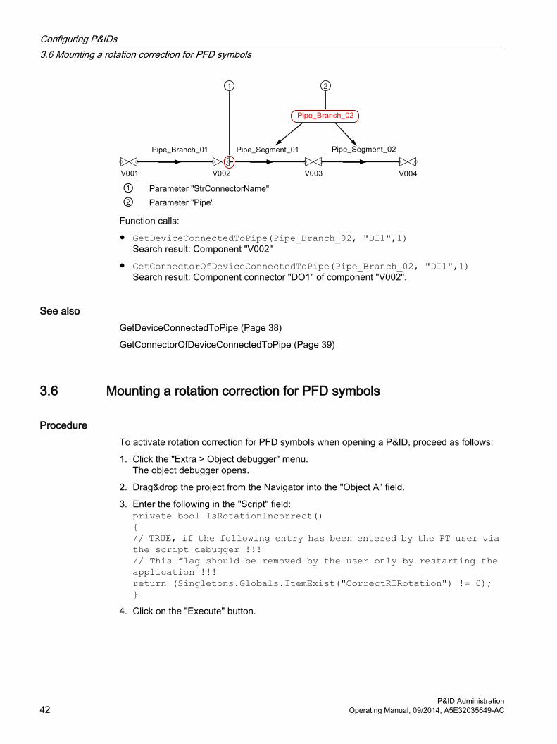
① Parameter "StrConnectorName"② Parameter "Pipe"
Function calls:
● GetDeviceConnectedToPipe(Pipe_Branch_02, "DI1",1) Search result: Component "V002"
● GetConnectorOfDeviceConnectedToPipe(Pipe_Branch_02, "DI1",1) Search result: Component connector "DO1" of component "V002".
See alsoGetDeviceConnectedToPipe (Page 38)
GetConnectorOfDeviceConnectedToPipe (Page 39)
3.6 Mounting a rotation correction for PFD symbols
ProcedureTo activate rotation correction for PFD symbols when opening a P&ID, proceed as follows:
1. Click the "Extra > Object debugger" menu.The object debugger opens.
2. Drag&drop the project from the Navigator into the "Object A" field.
3. Enter the following in the "Script" field:private bool IsRotationIncorrect(){// TRUE, if the following entry has been entered by the PT user via the script debugger !!!// This flag should be removed by the user only by restarting the application !!!return (Singletons.Globals.ItemExist("CorrectRIRotation") != 0);}
4. Click on the "Execute" button.
Configuring P&IDs3.6 Mounting a rotation correction for PFD symbols
P&ID Administration42 Operating Manual, 09/2014, A5E32035649-AC

ResultWhen you open a P&ID, rotation correction is applied for PFD symbols. Once you terminate COMOS, this setting is not applied the next time you start the program.
3.7 Mounting a scaling correction for PFD/P&ID symbols
ProcedureTo mount a scaling correction for PFD/P&ID symbols when loading a P&ID symbol script, proceed as follows:
1. Click the "Extra > Object debugger" menu.The object debugger opens.
2. Drag&drop the project from the Navigator into the "Object A" field.
3. Enter the following line in the "Script" field:A.workset.globals.RiConversionScale = <Scaling value>
4. Click on the "Execute" button.
ResultWhen you load a P&ID symbol script, scaling correction is applied for PFD/P&ID symbols. Once you terminate COMOS, this setting is not applied the next time you start the program.
Configuring P&IDs3.7 Mounting a scaling correction for PFD/P&ID symbols
P&ID AdministrationOperating Manual, 09/2014, A5E32035649-AC 43

Configuring P&IDs3.7 Mounting a scaling correction for PFD/P&ID symbols
P&ID Administration44 Operating Manual, 09/2014, A5E32035649-AC

Configuring components 44.1 Global preset of component refreshing
You can set up the project in such a way that COMOS automatically decides whether components should be refreshed and whether pipe spec mapping should be carried out.
Default for refresh componentsYou set the default for the window to refresh the components, e.g., via the object debugger. Use the following variable:
Workset.Globals.UpdateObject1 = Show and hide the "Refresh components" window
3 = No window, always refresh components
4 = No window, never refresh components
Default for pipe spec mappingYou set the default for carrying out pipe spec mapping via the object debugger, for example. Use the following variable:
Workset.Globals.ExecutePipeClass1 = Show and reset the window for pipe mapping
3 = No window, always carry out pipe spec mapping
4 = No window, never carry out pipe spec mapping
You can find more information on this topic in the "P&ID Operation" manual, keyword "".
4.2 Disabling automatic classification of componentsDisable this function so that components are not automatically assigned to a pipe during copying and pasting.
Procedure1. Open the base project.
2. Open the "System data" tab in the properties of a component.
3. Place the following catalog attribute on the tab.Path in the database: "@40 > A10 > Y00 > B10 > A90 > Y00A04713 Sorting locked"You can find additional information on this topic in the "COMOS Platform Administration" manual, keyword "Placing catalog attributes on tabs".
4. Enable the newly created option.
P&ID AdministrationOperating Manual, 09/2014, A5E32035649-AC 45

See alsoDependencies when copying and pasting objects (Page 50)
4.3 Changing the behavior of the flow directionThe "Cancel requirements" attribute changes the behavior of the flow direction.
You can find more information on this topic in the "P&ID Operation" manual, keyword "Changing the flow direction of multiple objects".
Procedure1. Open the properties of a base object on which you would like to set the attribute.
2. Select the "Attributes > System data" tab.
3. Go to design mode.
4. In the base data, navigate to the attribute "@40 > A10 > Y00 > A20 > C20 > Y00A00992 > Y00A00992 Cancel requirements".
5. Place the attribute on the selected tab.
6. Confirm your entries.
ResultThe standard table "Y10 > M20 > A10 > Y10M20N00011 Cancel conditions for flow direction" is stored at the "Cancel requirements" attribute. Depending on which value the user selects at the engineering end, the attribute has the following effects:
"Name" column "Description" column Column "Value 1"
Result
A000 - A000 This is the default setting. Ap‐plies if no value or an invalid value has been entered.Symbol is mirrored; the pipe run is processed further.
A010 Cancel A010 Start or target; flow direction is not changed; the pipe run is not processed any further.
A020 Multiway object A020 Flow direction is not changed; the pipe run is processed fur‐ther.
COMOS uses the "Cancel requirement = 0" attribute to check whether there are several flows for a component that have been defined with the following attribute: "Multiway object". See also section Determining the flow direction with multiway objects (Page 47).
If the flow direction changes, COMOS only mirrors the connectors affected by the change in flow direction.
Configuring components4.3 Changing the behavior of the flow direction
P&ID Administration46 Operating Manual, 09/2014, A5E32035649-AC
4.4 Determining the flow direction with multiway objectsYou use this attribute on multiway objects. The "Multiway object" attribute can be set at the component so that multiple connectors dependent on the flow direction can be used.
You can find more information on this topic in the "P&ID Operation" manual, keyword "Change in flow direction for multi-way objects".
Procedure1. Open the properties of a base object on which you would like to set the attribute.
2. Select the "Attributes > System data" tab.
3. Go to design mode.
4. In the base data, navigate to the attribute "@40 > A10 > Y00 > A90 > C20 > Y00A04491 Multiway object".
5. Place the attribute on the selected tab.
6. Confirm your entries.
Defining the flow directionAfter you have set the "Multiway object" attribute on the component, you can define the flow direction in the attribute. Define the flow directions by defining the connector pairs.
Separate the associated connectors of the multiway objects with a semicolon.
Example: "Multiway object = DI1>DO1;DI2>DO2"
ResultWhen the flow direction at a connector changes, the connector is swapped with its partner connector. The change of flow direction is passed on to the connected pipe.
4.5 Forcing action linesTo have an action line drawn instead of a pipe when you connect a component to other components or pipes, set one of the following combinations of functional classification keys at the component:
● 01C7; C160
● 01C7; C170
You can find more information on this topic in the "P&ID Operation" manual, keyword "Signal lines".
Configuring components4.5 Forcing action lines
P&ID AdministrationOperating Manual, 09/2014, A5E32035649-AC 47

Configuring components4.5 Forcing action lines
P&ID Administration48 Operating Manual, 09/2014, A5E32035649-AC

Copying/cutting and pasting 55.1 Overview of copying/cutting and pasting
"SetDeviceOwnerByConnector" scriptThis script determines where a pipe separating component is inserting:
● For components that separate piping sections: Next to the connected pipe object
● For components that separate piping segments: Under to the connected pipe object
P&ID AdministrationOperating Manual, 09/2014, A5E32035649-AC 49

Pipe separation components are moved to the same unit structure in which the pipe is located.
5.2 Dependencies when copying and pasting objectsNotes on terminology: Fitting = Fitting
The dependencies that exist when you paste objects are listed below. These dependencies have an effect on the paste behavior and the paste location.
The copied objects are inserted according to the paste mode if they were connected with a pipe during pasting, but the pipe does not call the SetOwnerbyDeviceConnector function in the Connect script.
Which objects were selected?A number of object types have a special form of paste behavior:
● Objects with the class: "Function", subclass: "None"
● Components identified as fittings:"System data" tab, enable "Sort parallel to the disconnected pipe branch" option Example: Valves and reductions
Some objects require a specific owner structure.
Example: Functions and pipes.
In this case, in addition to a copy of the original being pasted, a copy of the owner structure is created as well.
Copying/cutting and pasting5.2 Dependencies when copying and pasting objects
P&ID Administration50 Operating Manual, 09/2014, A5E32035649-AC

Which paste mode was selected?The diagram below gives you an overview of the interaction between these factors. The exact behavior of pipes and functions during copying and pasting is not part of this overview. Information regarding this can be found in separate sections:
● With regard to pipes: You can find more information on this topic in the "P&ID Operation" manual, keyword "Pipe segments and pipe sections".If an object is placed on a pipe when pasted, the pipe is separated according to the pipe cut mode of the object.
● With regard to functions: You can find more information on this topic in the "P&ID Operation" manual, keyword "".
Is the object connected with a pipe during pasting?In this case, the Connect event of the pipe is triggered and the function SetDeviceOwnerbyConnector is called in the event.
Function call:
Workset.lib.ri.SetDeviceOwnerbyConnector connector,true
Copying/cutting and pasting5.2 Dependencies when copying and pasting objects
P&ID AdministrationOperating Manual, 09/2014, A5E32035649-AC 51

You can prevent the automatic classification of components. See also section Disabling automatic classification of components (Page 45).
MoveComponents are moved automatically in the following cases:
● The component is located below the P&ID.
● The component is connected to a pipe.
● The pipe is assigned to a unit.
Example: A fitting is loosely placed on the P&ID. The fitting is later incorporated into a pipe.
See also section Dependencies when cutting and pasting objects (Page 54).
See alsoExamples of copying and pasting (Page 52)
5.3 Examples of copying and pastingA distinction is made between two possible statuses in the examples.
● The automatic sorting of new objects on the P&ID into categories is activated.SortNewObjectsInCategories = TRUE
● The automatic sorting of new objects on the P&ID into categories is deactivated.SortNewObjectsInCategories = False
See also section Automatically sorting objects into categories when placing them on the P&ID (Page 32).
Example 1Initial situation:
● A subunit with P&ID and categories has been created.
● A pump and its connected pipe are located underneath the main unit. They have been placed on the P&ID.
Action:
The pump and one of its connected pipe sections is copied to the P&ID. They are pasted using the command "Paste > Below document". The copies are not connected to another pipe when they are pasted.
● Result 1: SortNewObjectsInCategories = FALSESince the copied objects were not connected to a pipe when they were pasted, they are pasted in the Navigator according to the paste mode – i.e. in the Navigator under the P&ID.
● Result 2: SortNewObjectsInCategories = TRUESortNewObjectsInCategories overwrites the paste mode – the pasted objects are sorted in the Navigator into the category folders located parallel to the P&ID.
Copying/cutting and pasting5.3 Examples of copying and pasting
P&ID Administration52 Operating Manual, 09/2014, A5E32035649-AC

Example 2Initial situation:
● A subunit with P&ID and categories has been created.
● A valve without the activated "Sort parallel to the disconnected pipe segment" option that is not connected is located underneath the main unit.
● A pipe with a pipe section is located below the main unit.
● All objects have been placed on the P&ID.
Action:
The valve is copied and pasted using the command "Paste > Below document". It is placed on the pipe section when it is pasted.
● Result 1: SortNewObjectsInCategories = FALSEBecause the Connect script of the pipe section is called and the valve is not a fitting, it is pasted in the Navigator parallel to the connected pipe.
● Result 2: SortNewObjectsInCategories = TRUEThe valve is sorted into a category underneath the subunit. The pipe, which was not part of the paste set, remains underneath the main unit.
Example 3Initial situation:
● A subunit with P&ID and categories has been created.
● A valve that has a fitting and has not been connected is located underneath the main unit.
● A pipe with a pipe section is located below the main unit.
● All objects have been placed on the P&ID.
Action:
The valve is copied and pasted using the command "Paste > Below document". It is placed on the pipe section when it is pasted.
Because the Connect script is called, the valve is a fitting and the SetDeviceOwnerByConnector call is in the script, it is sorted below the connected pipe regardless of the result in the Navigator.
Fitting: Assignment to pipe sectionsIf the component meets the following criteria, there is no move to the new pipe when you dock a new pipe to this component:
● The "Sort parallel to the disconnected pipe branch" option is available and enabled at the component in the "System data".
● The component is placed in accordance with the "Sort parallel to the disconnected pipe branch" option.
● The component is already connected to a pipe section
Copying/cutting and pasting5.3 Examples of copying and pasting
P&ID AdministrationOperating Manual, 09/2014, A5E32035649-AC 53
See also"System data" tab (Page 80)
Dependencies when copying and pasting objects (Page 50)
5.4 Dependencies when cutting and pasting objectsNotes on terminology: Fitting = Fitting
Interaction of the factors relevant for pastingThe paste behavior and the paste location are determined by the same factors as for copying and pasting. See also section Dependencies when copying and pasting objects (Page 50).
The diagram below offers an overview of the interaction between these factors. The exact behavior of pipes and functions during cutting and pasting is not part of this overview. Information regarding this can be found in separate sections:
● With regard to pipes: You can find more information on this topic in the "P&ID Operation" manual, keyword "Pipe segments and pipe sections".When an object is placed on a pipe during pasting, the pipe is cut according to the pipe cut mode of the object.
● With regard to functions: You can find more information on this topic in the "P&ID Operation" manual, keyword "Functions/Positions".
If the component is to be pasted parallel to the connected pipe and the pipe is located in a category, a search is made for a category located in parallel into which the component can be sorted.
See alsoExamples of cutting and pasting (Page 54)
5.5 Examples of cutting and pastingNotes on terminology: Fitting = Fitting
A distinction is made between two possible statuses in the examples.
● The automatic sorting of new objects on the P&ID into categories is activated.SortNewObjectsInCategories = TRUE
● The automatic sorting of new objects on the P&ID into categories is deactivated.SortNewObjectsInCategories = FALSE
See also section Automatically sorting objects into categories when placing them on the P&ID (Page 32).
Copying/cutting and pasting5.5 Examples of cutting and pasting
P&ID Administration54 Operating Manual, 09/2014, A5E32035649-AC

Example 1Initial situation:
● A subunit with P&ID and categories has been created.
● A pump and its connected pipes are located underneath the main unit. There is an additional pipe underneath the main unit.
● All objects have been placed on the P&ID.
Action:
The pump is cut and pasted using the command "Paste > Below document". It is placed on the second pipe when it is pasted.
Pipe cut mode: "Pipe separative"
● Result 1: SortNewObjectsInCategories = TRUEThe user is prompted to decide which pipe is to be retained. The redundant pipe is deleted, together with its pipe section. The pump is sorted into a category that is located parallel to the P&ID. When placed on the second pipe, the pipe is separated into two pipes. The new pipe and its pipe section are created parallel to the old pipe, i.e. below the main unit.
● Result 2: SortNewObjectsInCategories = FALSEThe position of the pump in the Navigator remains the same.
Example 2Initial situation:
● A subunit with P&ID and categories has been created.
● Two pipes are located underneath the main unit. A valve is located underneath pipe A. The "Sort parallel to the disconnected pipe branch" option is enabled at the valve in the "System data". It is connected to the pipe segments of pipe A.
● All objects have been placed on the P&ID.
Action:
The valve is cut from pipe A and pasted using the command "Paste > Below document". It is placed on pipe B when it is pasted.
The second pipe segment below pipe A is deleted as a result of cutting the valve. Pipe B is segmented when the valve is pasted. Because the valve is connected with the pipe and is a fitting, it is sorted parallel to the pipe segment that it is connected to, that is, below the pipe, regardless of the result.
Copying/cutting and pasting5.5 Examples of cutting and pasting
P&ID AdministrationOperating Manual, 09/2014, A5E32035649-AC 55

Example 3Initial situation:
● Subunit with P&ID and categories.
● Two pipes are located underneath the main unit. Pipe A is located underneath the main unit. A valve is located underneath the pipe. The valve is a fitting and is connected with the pipe segments of the pipe.
● All objects have been placed on the P&ID.
Action:
The valve and one of its connected pipe segments, pipe segment B, is cut and pasted using the command "Paste > Below document". The objects are not connected with another pipe when they are pasted.
● Result 1: SortNewObjectsInCategories = TRUEThe valve and pipe segment B are deleted from the structure below pipe A. Then they are sorted into the categories underneath the subunit. Because the pipe segment must be located below a correct pipe structure, the pipes and the pipe section are copied beforehand and pasted as the owners of pipe segment B into the category for pipes.
● Result 2: SortNewObjectsInCategories = FALSEThe valve and pipe segment B are deleted from the structure below pipe A. In the same way as above, the pipe and the pipe section are also copied; they are pasted as the owner of pipe segment B according to the paste mode, i.e. below the document.
See also"System data" tab (Page 80)
Dependencies when cutting and pasting objects (Page 54)
5.6 Enabling copying if the hierarchical structure up to a position
ProcedureTo automatically create the complete hierarchical structure from a value up to the position when copying, proceed as follows:
1. Open the base object of a valve.
2. Open the "Attributes > System data" tab.
3. Go to design mode.
4. In the "@40" node of the "Base objects" tab, search for the attribute "Y00A04533 Copy structure up to position".
5. Drag&drop the attribute into the "System data" tab.
6. Change visual type to "Checkbox" in the properties of the attribute.
7. Change to working mode.
Copying/cutting and pasting5.6 Enabling copying if the hierarchical structure up to a position
P&ID Administration56 Operating Manual, 09/2014, A5E32035649-AC

8. Enable the option.
9. Confirm your entries.
You can find more information on this topic in the "P&ID Operation" manual, keyword "Functions / positions".
Copying/cutting and pasting5.6 Enabling copying if the hierarchical structure up to a position
P&ID AdministrationOperating Manual, 09/2014, A5E32035649-AC 57

Copying/cutting and pasting5.6 Enabling copying if the hierarchical structure up to a position
P&ID Administration58 Operating Manual, 09/2014, A5E32035649-AC

Changing color settings globally 66.1 Overview
The option to change color settings globally gives you the opportunity to temporarily alter the color settings of the symbols of objects placed on an P&ID. To do this, COMOS makes reference to predefined rules which are stored in one or a number of queries.
6.2 QueriesThe color queries are based on an engineering object query to which a color has been assigned. You can customize the color queries in such a way that the color of the symbols only changes under certain conditions.
Prepared queries: Base project, "Base objects" tab under the node "@20 > A70 > Y10 > M00 > A20 > M22_P1 P&ID (ISO 10628)".
The queries are arranged under a container object which is named after the object type to which the queries apply.
If you give users in the context menu of P&IDs access to the queries, the container objects are offered in the context menu. See also chapter Enabling color settings via the context menu (Page 60).
P&ID AdministrationOperating Manual, 09/2014, A5E32035649-AC 59
6.3 Assigning colors
Procedure1. Navigate to a query below the following node: "@20 > A70 > Y10 > M00 > A20 > M22_P1
P&ID (ISO 10628)".
2. Open the "Attributes > Color selection" tab in the properties of the query.
3. Click the "Select color" button.
4. Assign a color to the query.
6.4 Enabling color settings via the context menuYou can allow the user to make temporary color settings for symbols via the context menu of the P&ID.
Procedure1. Open the report template for the P&ID for which you wish to activate the mode.
2. Right-click on the working area of the report template.The context menu opens.
3. Select the "Options" command from the context menu.
4. Add the following line:UseColorSets = True
5. Confirm your entries.
Result● Users can set the color settings on all P&IDs that access the selected report template.
● In "Select color set" in the context menu, the container objects of queries are offered for selection. See also chapter Queries (Page 59). When the user clicks on one of the container objects, the objects are colored on the report according to the underlying query.
Changing color settings globally6.4 Enabling color settings via the context menu
P&ID Administration60 Operating Manual, 09/2014, A5E32035649-AC
Configuring the interfaces 77.1 Configuring XMpLant export
7.1.1 Administration of the "XMpLant" tabIn the XMpLant scheme, P&ID objects are saved as PlantItem nodes. In order to export objects in compliance with the standard, the interface requires certain metadata types from the P&ID objects. You have the possibility to choose from the following values for the metadata:
● Hard-coded default values in the software
● User-defined values
When using user-defined values, you must define them on the following tab:
● Name: "Y00T00277"
● Description: "XMpLant"
Inheritance sources of the "XMpLant" tabIn the database, the tab attributes are defined below the following node:
"@10 > A20 > A10 > A10 > Y00T00277 XMpLant".
Adding the "XMpLant" tab to the base dataIf a P&ID base object does not include the "XMpLant" tab, add it in the properties.
You can find more information on this topic in the "COMOS Platform Administration" manual, keyword "Adding tabs to base objects".
In the database, the tab is inherited to the following nodes:
● "@10 > A20 > A10 > A10 Physical objects":Result: All objects placed on a P&ID have the tab. No attribute values are set at this level. The configuration was not adapted to the component types until the below located levels.
● "@20 > A30 Functions":The configuration corresponds to the Function type.
Creating additional attributes on the "XMpLant" tabRather than using the tab that has been preconfigured in the "@10 > A20 > A10 > A10 > Y00T00277 XMpLant" node, you have the option of determining the attributes used on the "XMpLant" tab yourself.
You can find additional information on this topic in the "COMOS Platform Administration" manual, keyword "Creating an attribute".
P&ID AdministrationOperating Manual, 09/2014, A5E32035649-AC 61

The following applies:
● Default values are hard-coded in the software for all attributes of the "XMpLant" tab. When exporting an object, the default value of an attribute is only overwritten if the object has the corresponding attribute.
● You should configure the "PlantItemNodeName" attribute as high up in the base data as possible.In the database, a value is assigned to the attribute at the following levels:
– On the levels below "@10 > A20 > A10 > A10 Physical objects"
– "@20 > A30 Functions"
● Create all other attributes at the below located levels, depending on the respective project requirements.
Configuring attribute valuesFollowing applies when configuring attributes:
● Either you specify the attribute values in the base data or the users set the attribute values at the engineering end.
● With an export, values set on the engineering object in the "XMpLant" tab are always written to the XMpLant file.
● If no value was assigned to an attribute, an empty string is written to the export file.
Export without the "XMpLant" tabIf an object placed on the P&ID does not have an "XMpLant" tab: COMOS determines which PlantItem type corresponds to this object based on the "Class" and "Subclass" properties of the associated base object.
You will find these properties on the "General" tab of the base object.
Result● A PlantItem node of the corresponding type is created for the object in the export file.
● Objects whose class and subclass have no corresponding "PlantItem type" are exported as equipment (for example: revision clouds).
● The hard-coded default values are assigned to the PlantItem node attributes.
You can find additional information on this topic in the "P&ID Operation" manual, keyword "Attributes of the XMpLant tab".
7.1.2 Hard-coded PlantItem typesFor certain objects, hard-coded PlantItem types are used regardless of the value the "PlantItemNodeName" attribute has on the "XMpLant" tab.
Configuring the interfaces7.1 Configuring XMpLant export
P&ID Administration62 Operating Manual, 09/2014, A5E32035649-AC

PipesThe following PlantItem types are used for pipes:
Three-level pipe structure Two-level pipe structure (pipe sec‐tion and pipe segment)
Pipe "PipingNetworkSystem" "PipingNetworkSystem" dummy node
Pipe section "PipingNetworkSegment" See three-level structurePipe segment Not an own PlantItem node. A Cen‐
terline node is created underneath the corresponding PipingSegment node. The Centerline can have any number of coordinate nodes.
See three-level structure
Functions and positionsThe following PlantItem types are used for functions: "ProcessInstrument"
7.2 Configuring XMpLant export
7.2.1 Creating "OnXMpLantImportDone" at COMOS objectsYou can insert the OnXMpLantImportDone subprogram at the following base objects:
● P&ID objectsIf you specify a component class in the properties of a P&ID base object in the "Attributes > XMpLant" tab and this coincides with the component class of imported base objects, the objects are linked together. The imported base objects obtain the properties and scripts of the existing base object with which they are linked. If engineering objects are created during the XMpLant import, the OnXMpLantImportDone subprogram is passed to them. Once the import is complete, the subprogram is executed for each engineering object.
● P&IDsWhen you perform an XMpLant import in a P&ID that has the OnXMpLantImportDone subprogram, the subprogram is executed as soon as the import is completed.
Procedure1. In the base project, navigate to the base object in which you want to insert this script.
2. Open the "Script" tab in the properties.
3. Open a function.
4. Insert the following subprogram:Sub OnXMpLantImportDone...End Sub
Configuring the interfaces7.2 Configuring XMpLant export
P&ID AdministrationOperating Manual, 09/2014, A5E32035649-AC 63

5. Specify the contents of the script.
6. Click "OK".
7. If the function is not yet implemented, enable the option in the "Implemented" column.
8. Confirm your entries.
7.3 Configuration file for the DGN import
7.3.1 Configuration file "DGNImport1.xml"
Path to the configuration fileThe standard configuration file "DGNImport1.xml" can be found in the COMOS installation directory under the following path:
"<COMOS installation directory>\Current\Bin\OCX\WSP"
If you have deleted or renamed the configuration file, you can generate it automatically. To do this, proceed as follows:
1. Open the "Convert DGN drawing to engineering objects" window. You can find additional information on this topic in the "P&ID Operation" manual, keyword "Importing DGN file".
2. Click the "Options" button.
3. Click on the "Save" button in the "Options" window,but do not make an entry in the "Configuration file" field on the "Common" tab.
4. Click "Save".
7.3.2 Assigning a DGN line type to a COMOS line type
IntroductionAssign the DGN line types to the line types available for selection in COMOS on the "Line types" tab of the "Options" window. You can usually use the operating system line types you selected on the P&ID (using the context menu command "Options > Graphical properties").
RequirementThe "Options" window is open. See also section Configuration file "DGNImport1.xml" (Page 64).
Configuring the interfaces7.3 Configuration file for the DGN import
P&ID Administration64 Operating Manual, 09/2014, A5E32035649-AC

Procedure1. Select the "Line types" tab.
2. Select the required line type from the "COMOS line types" table.
3. Select the required DGN line type from the "Used DGN line types" table.Repeat steps one and two for each DGN line type to which you wish to assign a COMOS line type. Multiple selection is not possible.
4. To assign the selected line types to one another, click the "<<Assign" button.
5. Select one of the following options:
– Click "Save" to save the settings in the existing configuration file.
– Click "Save As" to save the settings in a new configuration file. Select the required directory. Enter a file name. Click "Save".
ResultBoth line types are assigned to each other and added to the "Assigned line types" list. The settings are written to the configuration file and saved as the default settings for DGN imports.
7.3.3 Assigning a DGN layer to a COMOS layer
IntroductionAssign the DGN layers to the COMOS layers available in the drawing type currently in use on the "Layers" tab of the "Options" window.
RequirementThe "Options" window is open. See also section Configuration file "DGNImport1.xml" (Page 64).
Procedure1. Select one or more DGN layers from the "Used DGN layers" table.
2. Select the required COMOS layer from the "Layers for the current symbol type" table.
3. To assign the selected layers to one another, click the "<<Assign" button.
4. Select one of the following options:
– Click "Save" to save the settings in the existing configuration file.
– Click "Save As" to save the settings in a new configuration file. Select the required directory. Enter a file name. Click "Save".
Configuring the interfaces7.3 Configuration file for the DGN import
P&ID AdministrationOperating Manual, 09/2014, A5E32035649-AC 65

ResultThe layers are assigned to each other and added to the "Assigned layers" list. The settings are written to the configuration file and saved as the default settings for DGN imports.
7.3.4 Assigning a DGN font to a Windows font
IntroductionAssign the DGN fonts to the selected Windows fonts on the "Fonts" tab of the "Options" window
RequirementThe "Options" window is open. See also section Configuration file "DGNImport1.xml" (Page 64).
Procedure1. Click the "..." button next to the "Path to the font resource files:" field.
The "Search folder" window opens.
2. Select the directory in which the DGN fonts are saved.
3. Click "OK".You return to the "Fonts" tab. The DGN fonts in the selected directory are listed in the table on the right.
4. Click "..." next to the mapping table.The "Font" window opens.
5. Select the required font.
6. If applicable, select the required font mode and font size.
7. Click "OK".You return to the "Fonts" tab.
8. Select one or more DGN fonts from the table on the right.
9. To assign the selected DGN fonts to the selected Windows font, click the "<<Assign" button.
10.Select one of the following options:
– Click "Save" to save the settings in the existing configuration file.
– Click "Save As" to save the settings in a new configuration file. Select the required directory. Enter a file name. Click "Save".
ResultThe fonts are assigned to one another and displayed in the mapping table. The settings are written to the configuration file and saved as the default settings for DGN imports.
Configuring the interfaces7.3 Configuration file for the DGN import
P&ID Administration66 Operating Manual, 09/2014, A5E32035649-AC

7.3.5 Undoing an assignment
RequirementYou have made assignments in the "Options" window.
ProcedureTo undo the assignment of the entries in the mapping table, proceed as follows:
1. Select one or more entries in the mapping table.
2. Click on the ">> Detach" button.
ResultThe selected entries are removed from the assignment list.
7.4 Pipe Easy
7.4.1 Adding the "Show PipeEasy conversion settings" button to the toolbar"Show PipeEasy conversion settings" button:
This button is not displayed on the toolbar of the P&ID by default. Use a script to add the button to the toolbar.
RequirementThe "std_PipeEasy" icon is available in the pictures library.
Procedure1. Open the report template for the P&ID containing the toolbar you wish to add the button to.
2. Right-click in the white area of the report template.
3. Select the "Options" command from the context menu.The "Options" window opens.
4. Enter the following script at the end of the '**PipeEasy Script section:UIObject.AddMenu UIObject.AddMenu "ComosImportUtilities.ImportUtilities:ShowSetupForm", "", "std_PipeEasy", MenuText
5. Click "OK" to save your input and close the "Options" window.
Configuring the interfaces7.4 Pipe Easy
P&ID AdministrationOperating Manual, 09/2014, A5E32035649-AC 67

ResultThe "Show PipeEasy conversion settings" button is added to the P&ID toolbar.
7.4.2 Configuring tabs of the "Conversion settings" window
OverviewThe "Conversion settings window comprises four tabs. You can hide tabs and define standard actions for text rules in the options script of the report template.
ExampleWhen you run the following script, only the "Assign texts" tab is displayed:UIObject.AddMenu "ComosImportUtilities.ImportUtilities:ShowSetupForm","DisabledTabs:0;2;3|DEFAULTACTION:1", "std_PipeEasy","Show conversion form"
7.4.3 Creating base objects for text rules
IntroductionFirst create an action base object under which the base objects for text rules are collected. Underneath this, create the number of base objects you require, with scripts describing texts.
RequirementThe base project is open.
Creating an action base objectTo create an action base object for text rules, proceed as follows:
1. Select the "Base objects" tab in the Navigator.
2. To do this, right-click on the node below which you wish to create the base object and select the "New > New base object" command from the context menu.The properties of the new object open.
3. Select "Action" from the "Class" list.
4. Select "Script" from the "Subclass" list.
5. Enter the desired name for the object, e.g. "T", in the "Name" field.
Configuring the interfaces7.4 Pipe Easy
P&ID Administration68 Operating Manual, 09/2014, A5E32035649-AC

6. Enter the desired description for the object, e.g. "Text assignment rules", in the "Description" field.
7. Click "OK" to create the object and close the properties window.
Creating base objects with scripts describing textsTo create a base object with scripts describing texts, proceed as follows:
1. Select the "Base objects" tab in the Navigator.
2. Right-click on the desired node of the action base object.
3. Select the "New > New base object" command from the context menu.The properties of the new object open.
4. Select "Action" from the "Class" list.
5. Select "Script" from the "Subclass" list.
6. Enter the desired name for the object in the "Name" field.Every base object must have the same name as its script function. Example: The base object "SetName" must have a script function called "SetName".
7. Enter the desired description for the object, e.g. "Rename object", in the "Description" field.
8. Add the required script to the "Script" tab.Make sure that the script function has exactly the same name as the base object.The script function must have a parameter array:
– Params(1): Comos object of the symbol
– Params(2): Text
– Params(3): ReportObject
– Params(4) ReportText (if selected) or Nothing (if name of an attribute is set)
9. Click "OK" to create the object and close the properties window.
ResultThe base object is created. If the function is completed successfully, an empty string ("") is returned. If the function is not completed successfully, a text is returned describing the error.
Script example 1:ChangeOwner: moves the object to unit UJ50Function ChangeOwner(Params) ChangeOwner = ""
Set Device = Params(1) Text= Params(2)
' Device->Document->DocFolder->Unit Set StartDev = Device.owner.owner.owner
For i = 1 To Len(Text)
Configuring the interfaces7.4 Pipe Easy
P&ID AdministrationOperating Manual, 09/2014, A5E32035649-AC 69

s = Mid(Text, i, 1)
If IsNumeric(s) Then s = Mid(Text, i) Set StartDev = StartDev.Devices.Item(s) If StartDev Is Nothing Then ChangeOwner = "Unit " & Text & " not found" Exit Function Else Exit For End If
End If
Set StartDev = StartDev.Devices.Item(s) If StartDev Is Nothing Then ChangeOwner = "Unit " & Text & " not found" Exit Function End If Next
Device.OwnerCollection.Remove Device StartDev.Devices.Add DeviceEnd Function
Script example 2:SetName: Rename COMOS objectFunction SetName(Params) SetName = "" Set Device = Params(1) Text= Params(2)
Device.Name = Text If Device.Check <> 0 Then SetName = "Invalid name" End IfEnd Function
7.5 PDF import
7.5.1 Rules for creating the PDF import
7.5.1.1 IntroductionIf, during the PDF import, COMOS finds a string to which one of your defined rules applies, COMOS automatically creates the object that you have previously specified for this string.
Configuring the interfaces7.5 PDF import
P&ID Administration70 Operating Manual, 09/2014, A5E32035649-AC

The rules applied to a PDF import for creating objects are collected in rule sets. The user selects a set of rules with any number of rules for each import.
You can find more information on this topic in the "P&ID Operation" manual, keyword "PDF import".
You create and manage the rule sets in the string rule manager.
7.5.1.2 Creating rule sets
RequirementYou are in the base project.
Procedure1. Select the "Administrator > Base data > String rule manager" command in the COMOS
menu.The String rule manager tab opens. See also chapter String rule manager (Page 101).
2. To create a new set of rules, click on the "New" button in the "Selected ruleset" control group.Enter a name for the rule set and confirm your entry.
3. To add a rule to the existing rule set, select the rule in the "All rules" area.
4. Click the "Left" button.The rule is added to the "Ruleset" control group.
5. To create a new rule, click on the "New" button in the "All rules" control group.See also chapter Creating a rule (Page 71).
6. Optional: Enter example texts in the "Text" column of the "Preview" control group in order to check whether the rules of the rule set recognize the texts and will therefore be able to import these texts.If a rule applies, it is displayed in the "Matching rule" column.
7. Optional: Click "Save".Saves the entered texts in a CSV file that you can reuse when you create new rules.
8. Confirm your entries.
ResultThe new rule set has been saved. When the user starts a PDF import, the set of rules is offered for selection in the "Ruleset" list in the preview window.
7.5.1.3 Creating a rule
RequirementThe "Create new rule" window is open.
Configuring the interfaces7.5 PDF import
P&ID AdministrationOperating Manual, 09/2014, A5E32035649-AC 71

Procedure1. Click "Create empty rule" in the "Data assignment" area.
2. Click "Edit rule".The "Splitting" window opens.You can find additional information on this topic in the "COMOS Automation Interfaces" manual, keyword "Working with the "Splitting" dialog".
3. Choose an entry from the "Select an operation" list.
4. Choose an entry from the "Predefined expressions" list.
5. Define the rule for the selected entry in the "Regular expression" field.
6. Confirm your entries.
7. Drag&drop a base object from the "Data assignment" area into the "Base object" field.Permitted:
– Base objects (CDevice)
– Documents (Document)
8. Optional: Click the "Extended rule options" button. You can find additional information on this topic in the "COMOS Automation Interfaces" manual, keyword "Extended rule options".
9. Confirm your entries.
ResultYou have created a new rule that you can assign to one or more rule sets.
Configuring the interfaces7.5 PDF import
P&ID Administration72 Operating Manual, 09/2014, A5E32035649-AC

Assigning a process coupling to functions 8For a process coupling to be created in addition when a measurement function or actuating function is created, you need to configure the base object of the function.
RequirementThe following parameter is set in the options script of the report template:
EnableProcessConnection = TRUEThe automatic creation of the process coupling can also be set separately for measurement functions and actuating functions:
● Only generate for measurement functions:EnableProcessConnectionSensor = True
● Only generate for actuating functions:EnableProcessConnectionActor = True
Procedure1. On the base data end, open the "Attributes > System data" tab in the properties of a function.
2. Go to design mode.
3. Navigate to the following attribute:"@40 > A10 > Y00 > A70 > B30 > Y00A03278 > Y00A03278 Component for process coupling".
4. Drag&drop the attribute into the "System data" tab.
5. Set the value "Reference" in the "Type of display" list in the attribute properties.
6. Confirm your entries.
7. Change to working mode.
8. Drag&drop a process coupling to the "Component for process coupling" field.Example: "@30 > M00 > A50 > A10 > A60 > A20 > A10 > A30 Nozzle for functions"
NoteChanging the process coupling
For the user to be able to change the process coupling, the "Y00T00001.Y00A03278" attribute must also exist at the nozzle that you dragged to the "Component for process coupling" field. You can refer to an inline device there, for example. In the inline device, you then refer back to the nozzle so that the user can switch between the inline device and the nozzle.
ResultIf the function is created on the engineering end, the process coupling is also created.
P&ID AdministrationOperating Manual, 09/2014, A5E32035649-AC 73

In the case of measurement functions, the process coupling is automatically connected not only visually on the report but also to the function (via its connectors). That is not the case for actuating functions. Reason: The valve still needs to be prepared further and will be assigned a drive. The function then needs to be connected with the drive.
Assigning a process coupling to functions
P&ID Administration74 Operating Manual, 09/2014, A5E32035649-AC

Increasing the processing speed 9"Sub Connect(Connector)" script
When you connect a component to pipes, the Sub Connect(Connector) script is called at the pipe sections.
The script contains the GetDeviceConnectedToPipe call and optionally the GetConnectorOfDeviceConnectedToPipe call. These calls determine the components connected to the pipe section. See also section Search modes (Page 39).
If connecting the pipes takes too much time, you should check whether the script "Connect" at pipe segments is really necessary.
1. Navigate to the base object of the pipe section in the base data.
2. Select the pipe segment on the "Elements" tab.
3. Open the properties of the element.
4. Select the "Script" tab.
5. Check whether the "Connect" script is necessary.
6. If the script is not always necessary, create a pipe base object in which this script is not always called.
See alsoGetDeviceConnectedToPipe (Page 38)
GetConnectorOfDeviceConnectedToPipe (Page 39)
P&ID AdministrationOperating Manual, 09/2014, A5E32035649-AC 75

Increasing the processing speed
P&ID Administration76 Operating Manual, 09/2014, A5E32035649-AC

Base data reference 1010.1 Base object "@10 > A20 > A10 P&ID"
The "@10 > A20 > A10 P&ID" base object node contains devices and administration objects that are required exclusively for pipes and instrumentation.
10.2 Base object "@20 > A80 > M22 > A10 Script library M22S00001 - M22S00050"
Base objects whose only purpose is to archive a script are managed in this branch. Therefore, these base objects have a script block on the "Script" tab but no other settings.
10.3 Base object "@10 > A20 > A10 > A10 Physical objects"
OverviewBase object node "@10 > A20 > A10 > A10 Physical objects" is a general catalog for devices.
All of the devices contained in this base object node have certain basic properties. Furthermore, there are objects that bring along additional properties and abilities.
10.3.1 Labeling
"Objects available for order" catalogThe sorting does not directly comply with the standard, but instead attempts to offer the most important sections of 26004 and 2401. The "Objects available for order" catalog does not constitute a complete labeling system that can be used immediately.
P&ID AdministrationOperating Manual, 09/2014, A5E32035649-AC 77

10.3.2 Symbol
Drawing typesAll simple devices have one or more symbols on the "Symbols" tab. As a rule, the drawing types "M21_P1", "M22_P1", "M22_P2" and "M22_P3" feature symbols:
● "M21_P1" drawing type: Main area of application in PFDs.
● "M22_P1" drawing type: Main area of application in chemical plants/DIN 28004 or new: ISO 10628.
● "M22_P2" and "M22_P3" drawing types: Main area of application in power stations / DIN 2481.
You can modify the symbols to suit your requirements. Symbols are hierarchically inherited downwards.
Graphical symbolYou can change the graphical symbols in the properties of the base object, on the "Symbols" tab. To open the Symbol Editor, double-click in the symbol column.
In the Symbol Editor, you can modify the graphical elements of the symbol using various drawing tools. You can find additional information on this topic in the "COMOS Platform Administration" manual, keyword "Configuring symbols".
The drawing type symbols have a fixed size and are optimized for a grid and a scale. Various options enable the symbols to also be used on P&IDs with a different grid and scale.
Each symbol has a placing point which is used for positioning on the grid. The green circles in the figure above identify the point of origin. The placement point only seldom coincides with the top left-hand corner, instead it is designed in such a way that the connectors can lie on the grid.
Base data reference10.3 Base object "@10 > A20 > A10 > A10 Physical objects"
P&ID Administration78 Operating Manual, 09/2014, A5E32035649-AC

To extend a graphical symbol, insert functions. The following function types are available:
● Functions that determine which connector points a symbol has and where they are attached to the symbol:
You can find additional information on this topic in the "COMOS Platform Administration" manual, keyword "Configuring connections".
● Functions that attach subsymbols, i.e. additional symbols, to the graphical main symbol.Example: A valve can receive a drive. If you have specified a drive, it should be added to the main symbol of the valve as a subsymbol.Whether or not the subsymbol has its own DocObj depends on which function is used to create the subsymbol. You can find additional information on this topic in the "COMOS Platform Administration" manual, keyword "Reference of subsymbols / additional symbols".
Text symbolsYou call text symbols in the properties of a base object, on the "Symbols" tab. To do this, double-click in the "Text" column. Define a text symbol that is attached to the graphical symbol of the object by means of *V* P Textpkt1*.
Many objects from the base object node "@10 > A20 > A10 > A10 Objects available for order" already have a text symbol on the top level.
This text symbol is inherited to all base objects below. It is only evaluated at the base objects that call the text symbol by means of *V* P Textpkt1*. You can find additional information on this topic in the "COMOS Platform Administration" manual, keyword "Text symbol".
The P&ID text symbol outputs the position of the device.
The header of the script for the text symbol contains blind entries: Header.Layer = "10"Header.Class = "e72"Layer "10" is a random number; it is used to bundle specific information. You can also enter another random layer. Depending on the individual data structure, it is necessary to ensure that you do not inadvertently use a layer that is already being used for some other purpose.
Header "e72" is a random description that is only used to bundle specific items of information. You can also enter another random header. Please note that a number of headers have been pre-assigned by the system. Thus, for example, Header.Class = "eZ" means that the text cannot be moved.
Base data reference10.3 Base object "@10 > A20 > A10 > A10 Physical objects"
P&ID AdministrationOperating Manual, 09/2014, A5E32035649-AC 79

Duplicate connectors in the symbolWhen you evaluate a P&ID symbol on a P&ID, a search is run for duplicate connectors. If COMOS finds a duplicate connector, the symbol on the P&ID is displayed as inconsistent (red) and a corresponding error entry is made in the error list.
A duplicate connector exists if there are at least two connectors in the symbol at the same position.
You can declare connectors with duplicate graphic links to be valid (so that no red connector point is drawn) by implementing a script function in "UserScriptBlock1" at the base object. For example, an inconsistency of this type caused by duplicate connector assignment by a process stream and a reference stream can be removed using the script.
Function IsPartnerConnectionValid( cc1, cc2, ValidationCode)
cc1 (input): COMOS connector of the dedicated engineering object.
cc2 (input): COMOS connector of the graphically linked partner engineering object.
ValidationCode (input): The status of the two COMOS connectors in relation to one another, where 1 means that the COMOS connectors are not interconnected because at least one of the two connectors might be linked to another connector.
IsPartnerConnectionValid (Output): Bool
● TRUE:The graphical connection is valid (no red connector).Con2 (a piece of equipment) connected to Con1 of the stream is not displayed in red.
● FALSE (default):The graphical connection is invalid (red connector).
10.3.3 Attributes, general
Device attributesEach device is provided with its own special attributes on the "Attributes" tab. The attributes are inherited hierarchically; if necessary, they are supplemented or modified by additional attributes at each level.
All attributes are managed centrally. The base object node "@40 > A10 Attributes catalog" is used for this purpose.
10.3.4 "System data" tabA description of some selected attributes in the "System data" tab is provided below.
"Sort parallel to the disconnected pipe branch" attributePipe components can obtain the following attribute:
"Y00T00001.Y00A01089 Sort parallel to the disconnected pipe branch"
Base data reference10.3 Base object "@10 > A20 > A10 > A10 Physical objects"
P&ID Administration80 Operating Manual, 09/2014, A5E32035649-AC

This attribute has the following properties:
● Visual type: "Checkbox".
● Value: "0"
● Inheritance source: "@40 > A20 > Y00 > A10 > A10 > Y00T00001 > A06 > B02 > Y00T00001 > Y00A01089 Sort parallel to the disconnected pipe branch"
If you select this option, the inserted component is always sorted parallel to the connected pipe section or pipe segment in the engineering view. This makes it part of the pipe structure.
If you deselect this option, the fitting is sorted either directly below the P&ID or into its designated category. How the fitting is sorted depends upon the options script of the report template or the unit configuration respectively.
You can find more information on this topic in the "P&ID Operation" manual, keyword "Sorting components under pipe elements by pipe cut mode".
Quick access to attributesBy default, you have quick access to the attributes of a selected object in the "Attribute filter" view of the properties tree. You can find additional information on this topic in the "COMOS Platform Administration" manual, keyword "Editing multiple objects in the properties tree".
10.4 Base object "@10 > A20 > A10 > A10 > A60 Elements and components"
GeneralUnder this base object node there are objects that, as a rule, are used as constituent parts of another object (the drives for valves, nozzles, and column fittings, for example).
These objects are then entered on the "Elements" tab for the main objects, making them available when you select the "New" command from the context menu.
10.4.1 Base object "@10 > A20 > A10 > A10 > A60 > A20 Nozzles and connections"
GeneralNozzles are used to connect pipes to objects or objects to pipes.
Using nozzlesFor a component to be connected automatically via a nozzle, the nozzle must have been input in the base data as an element of the component and must have the name "NOZZLE". Please note that the name is case-sensitive (all letters upper case)!
Base data reference10.4 Base object "@10 > A20 > A10 > A10 > A60 Elements and components"
P&ID AdministrationOperating Manual, 09/2014, A5E32035649-AC 81

You can create nozzles on the P&ID. Make a connection to the object on the P&ID. Select the "Create nozzle" option in the "Create connection" window.
The option is deactivated if the object does not have a "NOZZLE" element.
Nozzles with two connectorsA nozzle can also have two connectors instead of one.
If a nozzle with two connectors is used, the dynamic connector that is generated when creating the vessel is not deleted.
The one connector of the nozzle is joined with the pipe in the usual way. The second connector has to be created in such a way that it lies on the edge of the vessel in graphical terms and moreover, precisely at the point at which the dynamic connector of the vessel is created.
In this case the vessel connector is joined with the second connector of the nozzle.
Standard graphical P&ID mapping is used in this case. The connector from the vessel and the connector from the nozzle can find one another because they are located on top of one another.
The connection is broken if you move the nozzle. However, this cannot be seen at once on the P&ID, because the connector is located on the nozzle and continues to be displayed.
"Process data" tabInformation on the medium to be transported is collected here. Many of these attributes are linked and pass on their information via their connected components.
"Graphical options" tabInformation that is evaluated on the P&ID is stored here (e.g. description).
10.5 Base object "@30 > M00 > A50 > A10 > A80 Add. graphics and symbol drawing"
10.5.1 Base object "@30 > M00 > A50 > A10 > A80 > A10 Text symbols P&ID"Objects for pipe flags are prepared below this base object in the database.
Class: "Data set"
These objects create a text flay if they are dragged onto a P&ID. When the text flag is dragged onto a pipe, it then docks to the pipe and is automatically moved or deleted along with it.
These objects do not create objects in the engineering view but are only found on the P&ID. The objects of this base object node belong to pipes and must be placed in such a way that a connector to a pipe is created.
When you select a flag on the P&ID, the menu for the pipe is offered for selection from the context menu.
Base data reference10.5 Base object "@30 > M00 > A50 > A10 > A80 Add. graphics and symbol drawing"
P&ID Administration82 Operating Manual, 09/2014, A5E32035649-AC

Attributes"P&ID Options" tab:
● Inheritance source: "@10 > A20 > A10 > A20 > A10 > Y00T00039 Graphical options"
● "Y00T00039.Y00A00952 Graphical mirroring permitted"Activated: The text flag is turned around if the text flag is connected to a pipe and the flow direction is changed.Default = FALSE, Graphical flags (without text): TRUE Text flags: FALSE, otherwise there could be errors in the text assignment.
● "Y00T00039.Y00A01620 Automatic rotation permitted"Activated: The symbol is aligned to the symbol of the pipe. If the pipe is located vertically, the symbol is also placed vertically, and so forth. The texts within the symbol are rotated automatically in the appropriate direction. In this case the manual rotation is disabled. Although the rotation grab is still displayed, rotation does not have any effect and the flag always jumps back to the direction specified by the pipe.Default = FALSE, Graphical flags (without text): TRUE Text flags: FALSE, otherwise there could be errors in the text assignment.
● "Y00T00039.Y00A01621 Automatic selection permitted"Activated: Only takes effect if the text flag is connected to a pipe. When the pipe is selected, the text flag is automatically selected as well, even if the text flag no longer has any direct contact with the pipe.Default = FALSEObjects that can be selected along with their main object (i.e. their device is selected): TRUE Text flags (e.g. legends, etc.): FALSE
Text flags without direct contact to the pipeThe text flag can also be torn off after docking onto the pipe. The logical connection is retained and the text flag continues to output the pipe information.
Alternatively, the text flag can be freely positioned right from the beginning. The flag is then connected to the pipe as follows:
● Select pipe, "Copy" command from context menu
● Select text flag, "Reference > Connect with" command from context menu
10.5.2 Base object "@30 > M00 > A50 > A10 > A80 > A30 Graphical symbols P&ID"Class: "Element"
Subclass: "Graphic"
Objects that are based on these base objects are always created below the P&ID.
They are colored black by default. Later on these objects are not be sorted into one of the categories that are available under the unit.
Base data reference10.5 Base object "@30 > M00 > A50 > A10 > A80 Add. graphics and symbol drawing"
P&ID AdministrationOperating Manual, 09/2014, A5E32035649-AC 83

The color set on the P&ID can be changed by selecting "Options > Graphical properties" from the context menu.
Most of the objects from this base object node are placed on pipes. If the symbols touch a pipe, the pipe turns yellow.
Most of the objects that are created in the engineering view do not have any attributes. However, some of the objects have connectors and are connected to the pipe with these connectors when placed on a pipe.
Therefore some of the graphic symbols are introduced below.
Base object "@10 > A20 > A10 > A20 > A10 > A30 > A10 Pipe break"A pipe break is a symbol for a graphic break.
If you drag the base object onto the pipe, the pipe is interrupted visually and two break symbols are displayed.
The symbols have two grab points:
The grab point that is located on the arm of the break (figure on the left) scales the break symbols.
The grab point that is located on the pipe (figure on the right) increases the distance between the break.
The pipe is retained as a whole in the database, but it is segmented and joined with the connectors of the pipe break via its connectors.
Base object "@10 > A20 > A10 > A20 > A10 > A30 > A20 Page reference"A page reference is a symbol that groups connections across pages visually in one place on the P&ID. This page reference is created manually by the user on P&IDs. You can find more information on this topic in the "P&ID Operation" manual, keyword "Creating page references for two pipes".
Base object "@10 > A20 > A10 > A20 > A10 > A30 > B50 Revision cloud"A revision cloud is also a purely graphic piece of information. However, unlike the other base objects below "@10 > A20 > A10 > A20 > A10 > A30 Graphical symbols P&ID", the revision cloud does not belong to a pipe.
This object has a large number of freely movable grab points that you can use to shape the "cloud" in such a way that all required objects are included in it visually.
Base data reference10.5 Base object "@30 > M00 > A50 > A10 > A80 Add. graphics and symbol drawing"
P&ID Administration84 Operating Manual, 09/2014, A5E32035649-AC

The revision cloud has no effect on the COMOS revision.
10.6 Base object "@30 > M00 > A80 > A10 Document library objects acc. to IEC 61355"
Base objects of the report templates for P&ID. See also section Configuring P&IDs (Page 29).
10.7 Structure of the base objects of functionsIn the database, you find the functions below the base object "@20 > A30 Functions".
Measurement and actuating functionsObjects for measurement functions and actuating functions have been predefined under this node.
● You can find objects for measurement functions under "@20 > A30 > A10 > A20 Measurement function".
● You can find objects for actuating functions under "@20 > A30 > A10 > A30 Actuating function".
See also section Base object "@20 > A30 > A10 > A20 Measurement function" and "@20 > A30 > A10 > A30 Actuating function". (Page 86).
10.7.1 Base object "@20 > A30 > A10 > A10 General functions"
PlaceholdersWhen the user creates functions in the engineering project on level A1, these are "placeholders" of the "measurement function" or "actuating function" function type. A detailed specification of the function has not yet been drawn up or will not be drawn up. These functions are described as neutral or general functions. They are replaced by more concrete functions in I&C planning.
Function codeThe functions of this level have no function code. The base object does not change when you enter function codes.
Process connectorConnecting a wildcard function on a report to the process does not create a process connector.
Base data reference10.7 Structure of the base objects of functions
P&ID AdministrationOperating Manual, 09/2014, A5E32035649-AC 85

Creating reportsVarious evaluating reports can be created below functions on this and the following level. Reports are not needed until I&C planning.
10.7.2 Base object "@20 > A30 > A10 > A20 Measurement function" and "@20 > A30 > A10 > A30 Actuating function".
Functions already have a function type from this level onwards.
"@20 > A30 > A10 > A20 Measurement function"Path in the database: "@30 > M00 > A60 > A10 > A10 Measurement functions"
The objects correspond to DIN 19227.
A measurement function with this base object does not initially have a function code. When it is placed on the P&ID and connected with the process, it does not receive a process connector or any new tabs.
If you input a function code, a base object change takes place from this level onwards. If the function was connected with the process before the function code was input, it gets a process connector afterwards. You can find more information on this topic in the "P&ID Operation" manual, keyword "Creating a process connector".
On this level of the unit structure according to KKS you can find a structure that improves the bundling of the underlying measurement functions.
Levels below "@02 > 030 > 00 > 01 Measurement functions": The concrete functions as they actually required for I&C engineering start at this level.
"@20 > A30 > A10 > A30 Actuating function"This base object is a structure below which the actually creatable actuating functions are collected.
In the database, there are numerous structures under the functions from this level onwards. These structures are then made available in the engineering view via the "New" context menu. However, they are not required until the I&C planning stage and hence are covered in the I&C section. You can find more information on this topic in the "EI&C Administration" manual, keyword "@F functions".
10.7.3 ScriptsThe following scripts have been input at the base object of a function on the "Script" tab:
ConnectCall: when joining the connectors, thus, for example, when connecting the function on the P&ID.
Base data reference10.7 Structure of the base objects of functions
P&ID Administration86 Operating Manual, 09/2014, A5E32035649-AC

Task:
Measurement function: Connect only calls function SetCDev from UserScriptBlock1. If a function is connected to a piece of equipment or a pipe, the process connector is dynamically created and connected. Thus in this case Connect is also called.
Actuating function: Connect calls ConnectedObjectAsChild. An "DI" connector or a "CS" connector is created at the function, depending on the context.
You can find more information on this topic in the "P&ID Operation" manual, keyword "Process coupling for measurement function".
DisConnectCall: When disconnecting two connectors. If you reduce the number of process connectors, the connectors are separated as well. Thus DisConnect is called as well. Only with measurement functions.
When the call is made, the "SYS.AutoDeleteFreeConnectors" attribute (type: Boolean, i.e. checkbox) is queried on P&IDs at measurement functions. If the attribute exists and is set to "1", measurement function connectors which are not connected or are free are deleted. If you wish to use the attribute, you must create it yourself.
Task:
DisConnect calls function SetCDev from UserScriptBlock1.
OnEditOkCall: Whenever "OK" or "Apply" is pressed in the properties window. Only with measurement functions.
Task:
Measurement function: OnEditOk only calls function SetCDev from UserScriptBlock1.
OnReferencedByDeviceCall: When creating the function and on every change of base object.
Task:
Measurement function: When the function is created, it takes the first letter of the label of the position and thus becomes a suitable measurement function. If a mask is defined for the label at the base object, the mask wins out.
Thereafter, SetCDev is called from UserScriptBlock1. The base data can be simplified in this way: The same neutral functions are always located below the positions and the appropriate measurement function is created as a result of automatically taking over the label (and the subsequent change of base object in UserScriptBlock1).
Actuating function: Same as the measurement function, but here the actuating function takes the first letter from the label of the position and appends a "V".
Base data reference10.7 Structure of the base objects of functions
P&ID AdministrationOperating Manual, 09/2014, A5E32035649-AC 87

UserScriptBlock1This script block sets script variables and implements the SetCDevice function. The script variables do not necessarily have to be located in UserScriptBlock1.
1. PositionCDevFullNameAutomatically generates a position below the P&ID if a function is placed on the P&ID from the base data. The measurement function lies below the position. In order to put the mechanism into effect following prerequisites have to be met:
– This function needs to have a valid function letter in the label. If you use the base object of a very general function in the database, it will not have any function letters. Function letters are not added to the labels until lower levels. If you use a base object with function letters (and the other prerequisites are met), then the position is generated at the time the engineering object is created. If this is a general object you have to enter a function label at the engineering end. A base object change (pressure, temperature, etc.) takes place in response to the new function letter and the position is created.
– The function has to have the global variable PositionCDevFullName set in the script.It does not matter in which script block this global variable was set. The global variable states which position is used.
2. PositionCDeviceDefines which base object the owner position of the function gets. You can find more information on this topic in the "P&ID Operation" manual, keyword "Function is created by placing on the P&ID".
3. SetCDevice:Only for measurement function:
– Call:If the label is changed. The entered label is automatically written to the "@40 > A10 > Y00 > A10 > B60 > Y00A00365 Function" object. This attribute is queried in SetCDev. If the number of process connectors has been changed. The process connectors are controlled by the CProcess number of process connectors attribute.
– Task: SetCDevice checks whether the base object needs to change and determines the new base object.The Variable BaseCDevFullName identifies the base object node under which the search for the function base object should be carried out. SetCDevice then passes the label and the number of process connectors to the SetCDevBySpecs function. SetCDeviceBySpecs evaluates these parameters and changes the base object if necessary:First level below the node specified by BaseCDevFullName: depending on the function code.Second level: depending on the number of process connectors.
UserScriptBlock2AddToGraficalParameter: Adds the following attributes to the functions context menu:
● "Y00A03310 Function type"
● "Y00A00305 Output and operation"
Base data reference10.7 Structure of the base objects of functions
P&ID Administration88 Operating Manual, 09/2014, A5E32035649-AC

10.8 Base object "@30 > M00 > A50 > A10 > A10 > A10 Vessels and tanks"
Elements of the vesselPFD vessels can have hierarchically subordinate objects such as nozzles. These objects are created as elements of the vessel.
The base object of the vessel must have a nozzle with the name "NOZZLE" as an element so that the nozzle can be created automatically on connection. as described in section Base object "@10 > A20 > A10 > A10 > A60 > A20 Nozzles and connections" (Page 81).
MiscellaneousIn the database, vessels have the "Position" class and the "Equipment" subclass. You can find more information on this topic in the "P&ID Operation" manual, keyword "Positions".
10.9 Base object "@30 > M00 > A50 > A10 > A30 Valves"
ValvesThe valves are prepared in COMOS so that they can also be used as actuators. The actuators belong to the actuating functions. You can find more information on this topic in the "P&ID Operation" manual, keyword "Functions".
In the database, you can use the context menu to supplement the symbol for valves in the P&ID. You can display flange connectors and map safety positions, for example. To do this, set the attributes provided in the "UserScriptBlock1" script block. See also section Extending the graphical settings (Page 33).
10.10 Standard tablesThe following table describes the relevant standard tables:
Standard table Description"Standard tables > Y10 > M22 > A10 > Y10M22N00008 Pipe cut mode"
A connection to a P&ID is represented in the engineering data through a three-level structure. This value controls what hap‐pens in the engineering data if a component is placed on a pipe in the P&ID.You can find additional information on this topic in the "P&ID Operation" manual, keyword "Pipe cut mode".
"Standard tables > Y10 > M20 > A10 > Y10M20N00006 Pipe: termination symbols"
You can find additional information on this topic in the "CO‐MOS Platform Administration" manual, keyword "Pipeend‐symbol".
"Standard tables > Y10 > M00 > A10 > Y10M00N00008 User-defined line type"
Used to manage user-defined line types.You can find additional information on this topic in the "CO‐MOS Platform Administration" manual, keyword "Line types".
Base data reference10.10 Standard tables
P&ID AdministrationOperating Manual, 09/2014, A5E32035649-AC 89

Standard table Description"Standard tables > Y10 > M00 > A10 > Y10M00N00009 Drawing type specific line types>
For the assignment of user-defined line types to drawing types. You can find information on this topic in the "COMOS Platform Administration" manual, keyword "Line types".
"Standard tables > Y10 > M00 > A10 > Y10M00N00020 Con‐nection symbol (spec break)"
Contains drawing type specific scripts that compare whether two objects that are joined via their connectors match the attributes specified in the script. Only the attributes that are linked by their connectors are evaluated: The script is automatically evaluated when an object placed on the P&ID is evaluated. The script is called only once for each connector pair.It is implemented for the P&ID module for changes to pipe classes, nominal pressure and nominal diameter on a P&ID diagram.You can find additional information on this topic in the "P&ID Operation" manual, keyword "Standard pipe flags".
"Standard tables > @40 > Y00 > A10 > B70 > Y00N00390 Text selection P&ID"
Standard table for the management of text functions that are made available in the symbol editor.
"Standard tables > @40 > Y00 > A10 > B50 > Y00N00337 Line widths"
Specifies the line widths of PFD/P&I objects. Pipes also use this entry.
"Standard tables > @40 > Y00 > A10 > B50 > Y00N00338 Colors"
Specifies the colors of PFD/P&I objects. Pipes also use this entry.
"Standard tables > @40 > Y00 > A10 > A30 > Y00N00056 Failure behavior"
Stores symbols for the failure mode. For example, the stand‐ard table is assigned to attribute "Y00A00449.Y00A00449 Security position" so that it can be shown on the report as an additional symbol for the valve.
"Standard tables > Y10 > M20 > A10 > Y10M20N00008 Me‐dia line types"
A table of lines types is available on the P&I diagrams.
The system uses this standard table internally. You can use add to these tables, but not change delete them.You can find additional information on this topic in the "CO‐MOS Platform Administration" manual, keyword "Logocad line types".
"Standard tables > @40 > Y00 > A10 > B70 > Y00N00400 Flange display valves, pumps"
Stores symbols for the flanges of valves and pumps. As‐signed to attributes "Y00T00037.Y00A00886AA01 Flange joint 1", "Y00T00037.Y00A00886AA02 Flange joint 2" etc., which can be used to show and hide the flanges of the valve/pump on the report.
"Standard tables > Y10 > M00 > A10 > Y10M00N00010 Line types for action lines"
A list of action line types that are made available in P&I dia‐grams.The system accesses this standard table internally. You may extend but not modify or delete this table.You can find additional information on this topic in the "CO‐MOS Platform Administration" manual, keyword "Line types for action lines".
"Standard tables > @40 > Y00 > A10 > C20 > Y00N00481 Pipe branch
Defines the templates for pipe sections and the attribute val‐ues defined therein for the line type, the line width and the line color.
Base data reference10.10 Standard tables
P&ID Administration90 Operating Manual, 09/2014, A5E32035649-AC

Standard table Description"Standard tables > @40 > Y00 > A10 > B80 > Y00N00401 P&ID measuring position lettering"
The "%N position" function is used in the script of a symbol for an P&I measurement device. A search is also performed for the "PI > TEXTMOD" attribute in the script of the meas‐urement device on the measurement device. This attribute uses the standard table "P&ID measuring position lettering". If the attribute is there, the set value is read and formed in accordance with the text from "%N" position.
"Standard tables > Y10 > M00 > A10 > Y10M00N00006 Con‐nection types"
You can find a standard table under this node information for each connection type.You can find additional information on this topic in the "CO‐MOS Platform Administration" manual, keyword "Specifying line types for a connector".
10.11 Object classes of P&ID objects
Classes● Action
● Unit
● Connector
● Data record
● Document
● Document group
● Element
● Function
● Device
● Device request
● Location
● Position
● Revision
Subclasses● Equipment
● Blackbox
● Graphic
● Instrumentation
● Category
● Object query
Base data reference10.11 Object classes of P&ID objects
P&ID AdministrationOperating Manual, 09/2014, A5E32035649-AC 91

● Pipe
● Nozzles
● Symbol
You can find more information on this topic in the "COMOS Platform Operation" manual, keyword "Object classes for system types CDevice/Device".
Base data reference10.11 Object classes of P&ID objects
P&ID Administration92 Operating Manual, 09/2014, A5E32035649-AC

Script functions in the options script for P&ID 11P&IDs are assigned to the PFD application (options script, application = "PFD"). If you have selected this, specific script functions are available for you to use in the options script.
11.1 AutoConnectGrayboxes● AutoConnectGrayboxes = True (default value)
Pipes can be separated automatically by components within moved grayboxes.
● AutoConnectGrayboxes = FalsePipes cannot be separated automatically by components within moved grayboxes.
11.2 AutoPlaceTPiece (Integer)Option for "P&ID" type reports
● AutoPlaceTPiece = 1 When you draw a branch, the T-piece is always placed automatically.
● AutoPlaceTPiece = 2 The T-piece is never placed automatically.
● AutoPlaceTPiece = 3 The user is asked whether the T-piece should be placed.
11.3 AllowPrintingForDirectionArrow (Boolean)TRUE: The blue direction arrow at the connecting lines is printed as well.
FALSE (default): The direction arrow does not appear on the printout.
11.4 CheckAllOpenFunctionConns (Boolean)TRUE: Each measurement function that does not have a partner is regarded as inconsistent; this also includes any connections that the user has created but has failed to connect.
FALSE: Measurement function connections are only regarded as inconsistent if they have not been explicitly disconnected on the report by the user.
P&ID AdministrationOperating Manual, 09/2014, A5E32035649-AC 93

11.5 CheckAllOpenPipeConns (Boolean)TRUE : Each pipe that is not connected at both ends is regarded as inconsistent and shown in red.
FALSE (default): The pipe remains black.
11.6 CObjectFullNameForPipe (String)Specifies which base object is used if the "Connection" tool is used on a P&ID or PFD. Overwrites the setting from the project properties on the "Module options > Process engineering" tab. The base object that is set in the script is then used in all reports based on the report template.
Syntax:
"CObjectFullNameForPipe = "Obj.SystemFullName""
Examples:● For P&IDs:
CObjectFullNameForPipe = "@30|M00|A50|A10|A40|A10|A10"● For PFDs:
CObjectFullNameForPipe = "@10|A10|A10|A10|A40|A90" You find more information on this topic in the "P&ID" manual, keywords "Start configurations" and "Document base objects".
11.7 ConnectorRadius (Double)Specifies the radius of the connectors.
Default=1
11.8 CopyMainBranch (String)
UseUse the CopyMainBranch report option to specify how COMOS should behave when a pipe branch is created. If the report option CopyMainBranch is set, the report option CopyPipeConnectionAutoOff is ignored.
Script functions in the options script for P&ID11.8 CopyMainBranch (String)
P&ID Administration94 Operating Manual, 09/2014, A5E32035649-AC

You can make the following settings (the values have to be specified in quotation marks):
● CopyMainBranch = "Always"Specifies that the pipe substance data should always be applied to a pipe branch.
● CopyMainBranch = "Never"Specifies that the pipe substance data should never be applied to a pipe branch. COMOS inserts a standard pipe for the pipe branch.
● CopyMainBranch = "Ask"Specifies that the user is able to determine the desired behavior via a dialog when creating a pipe branch.
You can find additional information on this topic in the "P&ID" manual, keyword "CopyPipeConnectionAutoOff".
11.9 CopyPipeConnectionAutoOff
UseThe report option CopyPipeConnectionAutoOff is used to specify that the user can select the behavior of COMOS when creating a a pipe branch using the dialog "Create connection" .
To use the settings of the report option CopyPipeConnectionAutoOff, deactivate the report option CopyMainBranch or set it to Ask.
The following settings can be made:
● CopyPipeConnectionAutoOff = False (default)The "Create connection" dialog is not displayed when a pipe section is created. COMOS inserts a copy of the pipe as a pipe section.
● CopyPipeConnectionAutoOff = TrueWhen you connect a pipe branch to a pipe, the "Create connection" dialog is displayed.The user has the following selection options in the "Create connection" dialog.
– "Yes"Creates a standard pipe. You can specify which one it is in the context menu.
– "None":As before, a copy is made of the pipe that is connected at the "From" side.
– "Memorize the answer for the current session"Saves the selected setting for the current COMOS session.
11.10 CreateDefaultPipeSegment (Boolean)Default = FalseDetermines whether a newly created pipe section should also be assigned a default pipe segment automatically.
Script functions in the options script for P&ID11.10 CreateDefaultPipeSegment (Boolean)
P&ID AdministrationOperating Manual, 09/2014, A5E32035649-AC 95

11.11 DrawPFDConnsUnderDocumentInBlue (Boolean)
UseIn COMOS, you can make a setting so that the objects associated with a P&ID plan are placed directly below the document in the Navigator.
Use the DrawPFDConnsUnderDocumentInBlue report option to specify whether P&ID connections should be displayed in blue in the Navigator if these connections are located directly under the document.
The following settings can be made:
● DrawPFDConnsUnderDocumentInBlue = trueSpecifies that the connections should be shown in blue in the Navigator.
● DrawPFDConnsUnderDocumentInBlue = falseSpecifies that the connections should not be shown in blue in the Navigator.
11.12 DrawPFDDevicesUnderDocumentInBlue (Boolean)
UseIn COMOS, you can make a setting so that the objects associated with a P&ID are placed directly below the document in the Navigator. By default, these P&ID objects are displayed in the Navigator in blue.
Use the DrawPFDDevicesUnderDocumentInBlue report option if you want to stop the objects being shown in blue.
The following settings can be made:
● DrawPFDDevicesUnderDocumentInBlue = true (default)Specifies that the P&ID objects should be shown in blue in the Navigator.
● DrawPFDDevicesUnderDocumentInBlue = falseSpecifies that the P&ID objects should not be shown in blue in the Navigator.
11.13 DrawPipeEndSymbol (Boolean)Example / Syntax: DrawPipeEndSymbol = TrueThe default value is FALSE.
Script functions in the options script for P&ID11.13 DrawPipeEndSymbol (Boolean)
P&ID Administration96 Operating Manual, 09/2014, A5E32035649-AC

Default setting when creating new pipe sections.
● TRUE: The end symbols (e.g. a needle at the input connector or output connector) that are contained in the standard table "Y10 > M20 > A10 > Y10M20N00006 Pipe: termination symbols", are output at the newly created pipe section.
● FALSE: The end symbols are not output to the newly created pipe section. However, this only applies until the user calls the "Show start and end symbol" command from the context menu to display the symbols for the selected pipe sections again on the document.The option does not apply to pipe segments or when DrawPipeEndSymbolForSegment = TRUE is also set.
11.14 DrawPipeEndSymbolForSegment (Boolean)Example / Syntax: DrawPipeEndSymbolForSegment = TrueThe default value is FALSE.
Default setting when creating new pipe segments. This is an extension of DrawPipeEndSymbol and only takes effect if DrawPipeEndSymbol = TRUE .
If the value is TRUE and DrawPipeEndSymbol = TRUE, the end symbols are also displayed at pipe segments. See also section DrawPipeEndSymbol (Boolean) (Page 96).
11.15 DrawPipeConnectorSymbol (Boolean)Example / Syntax: DrawPipeConnectorSymbol = TrueThe default value is True.
Default setting when creating new pipe segments:
● The page link symbol entered in the standard table "Y10 > M20 > A10 > Y10M20N00004 Pipe: sheet reference symbols", is displayed on the newly created pipe segment, and another segment of the same pipe section is placed on a different document.
● FALSE: The page link symbol is never output at the newly created pipe segment. However, this only applies to the pipe segments until the user calls the "Page link symbol visible" command from the context menu to display the symbol again on the document.
11.16 DrawPipeEndSymbolForVertices (Boolean)TRUE: The end symbol for the "corners" of the pipe is output on the entire report. The corresponding symbol script is taken from the following standard table:
Base project, "Standard tables > Y10 > M20 > A10 > Y10M20N00006 Pipe: termination symbols"
Name: 3
Description: Any
Drawing type: M22_* (symbol script)
Script functions in the options script for P&ID11.16 DrawPipeEndSymbolForVertices (Boolean)
P&ID AdministrationOperating Manual, 09/2014, A5E32035649-AC 97

Value 1: 3
False = Default
11.17 EnableContinueDrawingConnection
IntroductionIf the EnableContinueDrawingConnection report option is activated, the user can use the "Connection" tool to extend a pipe or channel structure.
ProcedureTo activate EnableContinueDrawingConnection mode, proceed as follows:
1. Open the report template for the report for which you wish to activate the mode.
2. Right-click on the working area of the report template.The context menu opens.
3. Select the "Options" command from the context menu.The "Options" window opens.
4. Find the EnableContinueDrawingConnection entry.
5. Comment in the EnableContinueDrawingConnection report option.If the value of the option is set to False, change it to True.
6. Click "OK" to save your input and close the "Options" window.
7. Click "Save" in the report template.
ResultThe EnableContinueDrawingConnection report option is activated for all reports which are based on the selected report template. The next time the user opens a corresponding report, the mode is available.
11.18 EnableInteractiveEditableTextsDefault = True● EnableInteractiveEditableTexts = True
You can edit editable texts on a P&ID.
● EnableInteractiveEditableTexts = FalseThe texts cannot be edited. For additional information on this topic, refer to the "P&ID" manual, keyword "Lock editable texts for editing".
Script functions in the options script for P&ID11.18 EnableInteractiveEditableTexts
P&ID Administration98 Operating Manual, 09/2014, A5E32035649-AC
11.19 SetImplementationByConcessionRI (Boolean)TRUE (default): Automatic setting of the implementation pointer for streams, if required.
Requirement: The ConcessionRI = TRUE command has been set beforehand in the options script.
This method is used in the area of concession documents (acceptance documents). Background: In the P&ID, all objects are usually placed on exactly one report. If the objects are placed and connected on a second report, then new connections are generated which overwrite the connections in the database.
If the ConcessionRI = TRUE option is activated, no connection is made in the database as a result of the duplicate placement, and the original connection information is thus retained.
To display the relationship between the connectors correctly in the Navigator, an implementation reference that shows the original connection is generated. Use SetImplementationByConcessionRI to disable the process for generating this implementation reference so that nothing is displayed in the Navigator.
The master report is opened for multiplacements while the "ConcessionRI" script option is being checked.
Background: The "ConcessionRI" script option is no longer valid for databases in which the "Y00T00001.Y00A04522 Setting of connection logic" attribute has been set at the base object of the documents. Therefore, no other documents need to be opened to determine the concession status.
11.20 SetPipeFlagOnCreate (Boolean)TRUE: The standard pipe flag is displayed automatically when a pipe is created. This means, the text script defined at the base object of the pipe section in the "Symbols" tab for the current drawing type is evaluated and displayed.
FALSE = Default
11.21 SortNewBranchUnderNewPipe (Boolean)
UseUse the SortNewBranchUnderPipe report option to specify how COMOS should sort new pipe sections in the Navigator when these are drawn onto an existing pipe.
The following settings can be made:
● SortNewBranchUnderPipe = False (default)COMOS sorts the new pipe section under the existing pipe in the Navigator.
● SortNewBranchUnderPipe = TrueCOMOS creates a new pipe structure in the Navigator for the new pipe section.
Script functions in the options script for P&ID11.21 SortNewBranchUnderNewPipe (Boolean)
P&ID AdministrationOperating Manual, 09/2014, A5E32035649-AC 99

11.22 StdPipeFlagNoColor (Boolean)Example / Syntax: StdPipeFlagNoColor = TrueToggles on and off the color display for the default pipe flag.
Vorgabewert ist False.
11.23 StdPipeNoReflect (Boolean)Example / Syntax: StdPipeNoReflect = TrueTrue switches off the mirroring (reflection) of pipe flags when the flow direction is reversed.
Vorgabewert ist False.
11.24 SynchronizePipeConSymbol (Boolean)TRUE: The page reference symbol is always aligned in the direction of the pipe (for oblique pipes, for example).
Changing the script option from FALSE to TRUE for objects that have already been placed can cause symbols or texts to move due to the resulting transformation.
FALSE = Default
11.25 SynchronizeStdPipeFlag (Boolean)TRUE: The standard flag is always aligned in the direction of the pipe (in particular for oblique pipes).
FALSE = Default
Script functions in the options script for P&ID11.25 SynchronizeStdPipeFlag (Boolean)
P&ID Administration100 Operating Manual, 09/2014, A5E32035649-AC

User interface reference 1212.1 String rule manager
Open: COMOS menu "Administrator > Base data > String rule manager"
P&ID AdministrationOperating Manual, 09/2014, A5E32035649-AC 101

"Rulesets" control group
Control element Description"Selected ruleset" list Contains all existing rule sets."New" button Opens the "Create new rule set" window.
In this window, enter the name for creating a new set of rules and confirm your entry.
"Delete" button Deletes the rule set that was selected in the "Selected rule set" list.Rules of the rule set This section contains the rules that were added to the rule set."Up", "Down" buttons You can use these buttons to change the order of the rules within a rule
set."Right", "Left" buttons You can use these buttons to assign and remove rules from the "All rules"
area to a set of rules."Preview" area You can use example texts here to check whether the rules in the rule set
recognize the texts. Enter the example text in the "Text" column. If a rule applies, the name of the rule is entered in the "Matching rule" column.
"Load" button Loads a previously saved CSV file with example texts for the preview. "Save" button Saves all example texts to a CSV file.
"All rules" control group
Control element DescriptionArea for the rules Displays a collection of all the rules that you have previously defined."New" button Opens the "Create new rule" window."Edit" button Opens the "Edit rule" window."Delete" button Deletes the selected rule.
See alsoCreating rule sets (Page 71)
User interface reference12.1 String rule manager
P&ID Administration102 Operating Manual, 09/2014, A5E32035649-AC