configuring ipv4 multicast layer 3 switching - cisco · configuring ipv4 multicast layer 3...
TRANSCRIPT
Cisco 7600 Series Router Cisco I
OL-10113-33
C H A P T E R 31
Configuring IPv4 Multicast Layer 3 SwitchingThis chapter describes how to configure IPv4 multicast Layer 3 switching on the Cisco 7600 series routers.
Note For complete syntax and usage information for the commands used in this chapter, refer to these publications:
• The Cisco 7600 Series Routers Command References at this URL:
http://www.cisco.com/en/US/products/hw/routers/ps368/prod_command_reference_list.html
• The Release 12.2 publications at this URL:
http://www.cisco.com/univercd/cc/td/doc/product/software/ios122/122cgcr/index.htm
This chapter consists of these sections:
• Understanding How IPv4 Multicast Layer 3 Switching Works, page 31-1
• Understanding How IPv4 Bidirectional PIM Works, page 31-6
• Default IPv4 Multicast Layer 3 Switching Configuration, page 31-7
• IPv4 Multicast Layer 3 Switching Configuration Guidelines and Restrictions, page 31-7
• Configuring IPv4 Multicast Layer 3 Switching, page 31-9
• Configuring IPv4 Bidirectional PIM, page 31-22
Understanding How IPv4 Multicast Layer 3 Switching Works
These sections describe how IPv4 multicast Layer 3 switching works:
• IPv4 Multicast Layer 3 Switching Overview, page 31-2
• Multicast Layer 3 Switching Cache, page 31-2
• Layer 3-Switched Multicast Packet Rewrite, page 31-3
• Partially and Completely Switched Flows, page 31-3
• Non-RPF Traffic Processing, page 31-5
• Understanding How IPv4 Bidirectional PIM Works, page 31-6
31-1OS Software Configuration Guide, Release 15 S
Chapter 31 Configuring IPv4 Multicast Layer 3 Switching Understanding How IPv4 Multicast Layer 3 Switching Works
IPv4 Multicast Layer 3 Switching Overview
The Policy Feature Card (PFC) provides Layer 3 switching for IP multicast flows using the hardware replication table and hardware Cisco Express Forwarding (CEF), which uses the forwarding information base (FIB) and the adjacency table on the PFC. In systems with Distributed Forwarding Cards (DFCs), IP multicast flows are Layer 3 switched locally using Multicast Distributed Hardware Switching (MDHS). MDHS uses local hardware CEF and replication tables on each DFC to perform Layer 3 switching and rate limiting of reverse path forwarding (RPF) failures locally on each DFC-equipped switching module.
The PFC and the DFCs support hardware switching of (*,G) state flows. The PFC and the DFCs support rate limiting of non-RPF traffic.
Also termed as hardware switching, Multicast Layer 3 switching forwards IP multicast data packet flows between IP subnets using advanced application-specific integrated circuit (ASIC) switching hardware, which offloads processor-intensive multicast forwarding and replication from network routers.
Layer 3 flows that cannot be hardware switched are still forwarded in the software by routers. Protocol Independent Multicast (PIM) is used for route determination and mcast rate-limiters limit the traffic relayed to the route processor.
The PFC and the DFCs all use the Layer 2 multicast forwarding table to determine on which ports Layer 2 multicast traffic should be forwarded (if any). The multicast forwarding table entries are populated in conjunction with Internet Group Management Protocol (IGMP) snooping (see Chapter 33, “Configuring IGMP Snooping for IPv4 Multicast Traffic”).
Current implementation of IPV4 multicast in 7600 uses the platform specific distribution mechanism from Route Processor (RP) to Switch Processor (SP). With the introduction of MFIB, MFIB provides support for distribution of the information in a platform independent way to the Switch Processor (SP) and Line cards (LC’s). In 12.2(33)SRE, this feature is supported on SUP720, Sup32, RSP720 and compatible DFCs.
For more information on the MDSS (Multicast Distributed Switching Services) implementation used prior to MFIB implementation, see: http://www.cisco.com/en/US/docs/ios/12_1/switch/configuration/guide/xcdmdc.html
Multicast Layer 3 Switching Cache
This section describes how the PFC and the DFCs maintain Layer 3 switching information in hardware tables.
The PFC and DFC populate the (S,G) or (*,G) flows in the hardware FIB table with the appropriate masks; for example, (S/32, G/32) and (*/0, G/32). The RPF interface and the adjacency pointer information is also stored in each entry. The adjacency table contains the rewrite information and pointers to the multicast expansion table (MET) table. If a flow matches a FIB entry, the RPF check compares the incoming interface/VLAN with the entry. A mismatch is an RPF failure, which can be rate limited if this feature is enabled.
The MSFC updates its multicast routing table and forwards the new information to the PFC whenever it receives traffic for a new flow. In addition, if an entry in the multicast routing table on the MSFC ages out, the MSFC deletes the entry and forwards the updated information to the PFC. In systems with DFCs, flows are populated symmetrically on all DFCs and on the PFC.
The Layer 3 switching cache contains flow information for all active Layer 3-switched flows. After the switching cache is populated, multicast packets identified as belonging to an existing flow can be Layer 3 switched based on the cache entry for that flow. For each cache entry, the PFC maintains a list of outgoing interfaces for the IP multicast group. From this list, the PFC determines onto which VLANs traffic from a given multicast flow should be replicated.
31-2Cisco 7600 Series Router Cisco IOS Software Configuration Guide, Release 15 S
OL-10113-33
Chapter 31 Configuring IPv4 Multicast Layer 3 Switching Understanding How IPv4 Multicast Layer 3 Switching Works
These commands affect the Layer 3 switching cache entries:
• When you clear the multicast routing table using the clear ip mroute command, all multicast Layer 3 switching cache entries are cleared.
• When you disable IP multicast routing on the MSFC using the no ip multicast-routing command, all multicast Layer 3 switching cache entries on the PFC are purged.
Layer 3-Switched Multicast Packet Rewrite
When a multicast packet is Layer 3 switched from a multicast source to a destination multicast group, the PFC and the DFCs perform a packet rewrite that is based on information learned from the MSFC and stored in the adjacency table.
For example, Server A sends a multicast packet addressed to IP multicast group G1. If there are members of group G1 on VLANs other than the source VLAN, the PFC must perform a packet rewrite when it replicates the traffic to the other VLANs (the router also bridges the packet in the source VLAN).
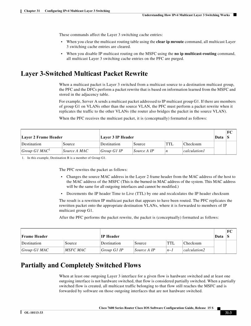
When the PFC receives the multicast packet, it is (conceptually) formatted as follows:
The PFC rewrites the packet as follows:
• Changes the source MAC address in the Layer 2 frame header from the MAC address of the host to the MAC address of the MSFC (This is the burned-in MAC address of the system. This MAC address will be the same for all outgoing interfaces and cannot be modified.)
• Decrements the IP header Time to Live (TTL) by one and recalculates the IP header checksum
The result is a rewritten IP multicast packet that appears to have been routed. The PFC replicates the rewritten packet onto the appropriate destination VLANs, where it is forwarded to members of IP multicast group G1.
After the PFC performs the packet rewrite, the packet is (conceptually) formatted as follows:
Partially and Completely Switched Flows
When at least one outgoing Layer 3 interface for a given flow is hardware switched and at least one outgoing interface is not hardware switched, that flow is considered partially switched. When a partially switched flow is created, all multicast traffic belonging to that flow still reaches the MSFC and is forwarded by software on those outgoing interfaces that are not hardware switched.
Layer 2 Frame Header Layer 3 IP Header DataFCS
Destination Source Destination Source TTL Checksum
Group G1 MAC1
1. In this example, Destination B is a member of Group G1.
Source A MAC Group G1 IP Source A IP n calculation1
Frame Header IP Header DataFCS
Destination Source Destination Source TTL Checksum
Group G1 MAC MSFC MAC Group G1 IP Source A IP n–1 calculation2
31-3Cisco 7600 Series Router Cisco IOS Software Configuration Guide, Release 15 S
OL-10113-33
Chapter 31 Configuring IPv4 Multicast Layer 3 Switching Understanding How IPv4 Multicast Layer 3 Switching Works
These sections describe partially and completely switched flow:
• Partially Switched Flows, page 31-4
• Completely Switched Flows, page 31-4
Partially Switched Flows
A flow might be partially switched instead of completely switched in these situations:
• If the router is configured as a member of the IP multicast group on the RPF interface of the multicast source (using the ip igmp join-group command).
• During the registering state, if the router is the first-hop router to the source in PIM sparse mode (in this case, the router must send PIM-register messages to the rendezvous point [RP]).
• If the multicast TTL threshold is configured on an outgoing interface for the flow (using the ip multicast ttl-threshold command).
• If the multicast helper is configured on the RPF interface for the flow, and multicast to broadcast translation is required.
• If the outgoing interface is a Distance Vector Multicast Routing Protocol (DVMRP) tunnel interface.
• If Network Address Translation (NAT) is configured on an interface and source address translation is required for the outgoing interface.
• Flows are partially switched if any of the outgoing interfaces for a given flow are not Layer 3 switched.
(S,G) flows are partially switched instead of completely switched in these situations:
• (S,G) flows are partially switched if the (S,G) entry has the RPT-bit (R bit) set.
• (S,G) flows are partially switched if the (S,G) entry does not have the SPT bit (T flag) set and the Prune bit (P flag) set.
(*,G) flows are partially switched instead of completely switched in these situations:
• (*,G) flows are partially switched on the last-hop leaf router if the shared-tree to shortest-path-tree (SPT) threshold is not equal to infinity. This allows the flow to transition from the SPT.
• (*,G) flows are partially switched if at least one (S,G) entry has the same RPF as a (*,g) entry but any of these is true:
– The RPT flag (R bit) is not set.
– The SPT flag(T bit) is not set.
– The Prune-flag (P bit) is not set.
• (*,G) flows are partially switched if a DVMRP neighbor is detected on the input interface of a (*,G) entry.
• (*,G) flows are partially switched if the interface and mask entry is not installed for the RPF-interface of a (*,G) entry and the RPF interface is not a point-to-point interface.
Completely Switched Flows
When all the outgoing interfaces for a given flow are Layer 3 switched, and none of the above situations apply to the flow, that flow is considered completely switched. When a completely switched flow is created, the PFC prevents multicast traffic bridged on the source VLAN for that flow from reaching the MSFC interface in that VLAN, freeing the MSFC of the forwarding and replication load for that flow.
31-4Cisco 7600 Series Router Cisco IOS Software Configuration Guide, Release 15 S
OL-10113-33
Chapter 31 Configuring IPv4 Multicast Layer 3 Switching Understanding How IPv4 Multicast Layer 3 Switching Works
One consequence of a completely switched flow is that multicast statistics on a per-packet basis for that flow cannot be recorded. Therefore, the PFC periodically sends multicast packet and byte count statistics for all completely switched flows to the MSFC. The MSFC updates the corresponding multicast routing table entry and resets the expiration timer for that multicast route.
Note A (*,G) state is created on the PIM-RP or for PIM-dense mode but is not used for forwarding the flows, and Layer 3 switching entries are not created for these flows.
Non-RPF Traffic Processing
These sections describe non-RPF traffic processing:
• Non-RPF Traffic Overview, page 31-5
• Filtering of RPF Failures for Stub Networks, page 31-6
• Rate Limiting of RPF Failure Traffic, page 31-6
Non-RPF Traffic Overview
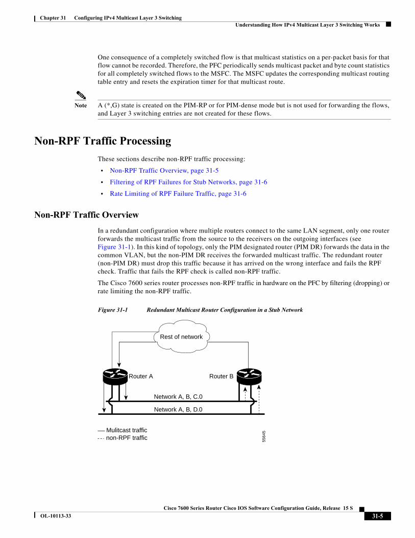
In a redundant configuration where multiple routers connect to the same LAN segment, only one router forwards the multicast traffic from the source to the receivers on the outgoing interfaces (see Figure 31-1). In this kind of topology, only the PIM designated router (PIM DR) forwards the data in the common VLAN, but the non-PIM DR receives the forwarded multicast traffic. The redundant router (non-PIM DR) must drop this traffic because it has arrived on the wrong interface and fails the RPF check. Traffic that fails the RPF check is called non-RPF traffic.
The Cisco 7600 series router processes non-RPF traffic in hardware on the PFC by filtering (dropping) or rate limiting the non-RPF traffic.
Figure 31-1 Redundant Multicast Router Configuration in a Stub Network
Network A, B, C.0
Network A, B, D.0
Rest of network
Router A Router B
Mulitcast trafficnon-RPF traffic
5564
5
31-5Cisco 7600 Series Router Cisco IOS Software Configuration Guide, Release 15 S
OL-10113-33
Chapter 31 Configuring IPv4 Multicast Layer 3 Switching Understanding How IPv4 Bidirectional PIM Works
Filtering of RPF Failures for Stub Networks
The PFC and the DFCs support ACL-based filtering of RPF failures for sparse mode stub networks. When you enable the ACL-based method of filtering RPF failures by entering the mls ip multicast stub command on the redundant router, the following ACLs automatically download to the PFC and are applied to the interface you specify:
access-list 100 permit ip A.B.C.0 0.0.0.255 anyaccess-list 100 permit ip A.B.D.0 0.0.0.255 anyaccess-list 100 permit ip any 224.0.0.0 0.0.0.255access-list 100 permit ip any 224.0.1.0 0.0.0.255access-list 100 deny ip any 224.0.0.0 15.255.255.255
The ACLs filter RPF failures and drop them in hardware so that they are not forwarded to the router.
Use the ACL-based method of filtering RPF failures only in sparse mode stub networks where there are no downstream routers. For dense mode groups, RPF failure packets have to be seen on the router for the PIM assert mechanism to function properly. Use CEF-based or NetFlow-based rate limiting to limit the rate of RPF failures in dense mode networks and sparse mode transit networks.
For information on configuring ACL-based filtering of RPF failures, see the “Configuring ACL-Based Filtering of RPF Failures” section on page 31-15.
Rate Limiting of RPF Failure Traffic
When you enable rate limiting of packets that fail the RPF check (non-RPF packets), most non-RPF packets are dropped in hardware. According to the multicast protocol specification, the router needs to receive the non-RPF packets for the PIM assert mechanism to function properly, so all non-RPF packets cannot be dropped in hardware.
When a non-RPF packet is received, a NetFlow entry is created for each non-RPF flow.
When the first non-RPF packet arrives, the PFC bridges the packet to the MSFC and to any bridged ports and creates a NetFlow entry that contains source, group, and ingress interface information, after which the NetFlow entry handles all packets for that source and group, sending packets only to bridged ports and not to the MSFC.
To support the PIM assert mechanism, the PFC periodically forwards a percentage of the non-RPF flow packets to the MSFC.
The first packets for directly connected sources in PIM sparse mode are also rate-limited and are processed by the CPU.
Rate limiting of RPF failures is enabled by default.
Understanding How IPv4 Bidirectional PIM WorksThe PFC3 supports hardware forwarding of IPv4 bidirectional PIM groups. To support IPv4 bidirectional PIM groups, the PFC3 implements a new mode called designated forwarder (DF) mode. The designated forwarder is the router elected to forward packets to and from a segment for a IPv4 bidirectional PIM group. In DF mode, the supervisor engine accepts packets from the RPF and from the DF interfaces.
When the supervisor engine is forwarding IPv4 bidirectional PIM groups, the RPF interface is always included in the outgoing interface list of (*,G) entry, and the DF interfaces are included depending on IGMP/PIM joins.
31-6Cisco 7600 Series Router Cisco IOS Software Configuration Guide, Release 15 S
OL-10113-33
Chapter 31 Configuring IPv4 Multicast Layer 3 Switching Default IPv4 Multicast Layer 3 Switching Configuration
If the route to the RP becomes unavailable, the group is changed to dense mode. Should the RPF link to the RP become unavailable, the IPv4 bidirectional PIM flow is removed from the hardware FIB.
For information on configuring IPv4 bidirectional PIM, see the “Configuring IPv4 Bidirectional PIM” section on page 31-22.
Default IPv4 Multicast Layer 3 Switching ConfigurationTable 31-1 shows the default IP multicast Layer 3 switching configuration.
Internet Group Management Protocol (IGMP) snooping is enabled by default on all VLAN interfaces. If you disable IGMP snooping on an interface, multicast Layer 3 flows are still switched by the hardware. Bridging of the flow on an interface with IGMP snooping disabled causes flooding to all forwarding interfaces of the VLAN. For details on configuring IGMP snooping, see Chapter 33, “Configuring IGMP Snooping for IPv4 Multicast Traffic.”
IPv4 Multicast Layer 3 Switching Configuration Guidelines and Restrictions
These sections describe IP Multicast Layer 3 switching configuration restrictions:
• Restrictions, page 31-7
• Unsupported Features, page 31-8
Restrictions
IP multicast Layer 3 switching is not provided for an IP multicast flow in the following situations:
• For IP multicast groups that fall into the range 224.0.0.* (where * is in the range 0 to 255), which is used by routing protocols. Layer 3 switching is supported for groups 225.0.0.* through 239.0.0.* and 224.128.0.* through 239.128.0.*.
Note Groups in the 224.0.0.* range are reserved for routing control packets and must be flooded to all forwarding ports of the VLAN. These addresses map to the multicast MAC address range 01-00-5E-00-00-xx, where xx is in the range 0–0xFF.
Table 31-1 Default IP Multicast Layer 3 Switching Configuration
Feature Default Value
ACL for stub networks Disabled on all interfaces
Installing of directly connected subnet entries Enabled globally
Multicast routing Disabled globally
PIM routing Disabled on all interfaces
IP multicast Layer 3 switching Enabled when multicast routing is enabled and PIM is enabled on the interface
31-7Cisco 7600 Series Router Cisco IOS Software Configuration Guide, Release 15 S
OL-10113-33
Chapter 31 Configuring IPv4 Multicast Layer 3 Switching IPv4 Multicast Layer 3 Switching Configuration Guidelines and Restrictions
• For PIM auto-RP multicast groups (IP multicast group addresses 224.0.1.39 and 224.0.1.40).
• For packets with IP options. However, packets in the flow that do not specify IP options are hardware switched.
• For source traffic received on tunnel interfaces (such as MBONE traffic).
• If a (S,G) entry for sparse mode does not have the SPT-bit, RPT-bit, or Pruned flag set.
• A (*,G) entry is not hardware switched if at least one (S,G) entry has an RPF different from the (*,G) entry’s RPF and the (S,G) is not hardware switched.
• If the ingress interface of a (S,G) or (*,G) entry is null, except if the (*,G) entry is a IPv4 bidirectional PIM entry and the router is the RP for the group.
• For IPv4 bidirectional PIM entries when a DF interface or RPF interface is a tunnel.
• Supervisor Engine 32 does not support egress multicast replication and cannot detect the multicast replication mode.
• In a MFIB implementation, ip multicast rate-limit command that limits the number of data packets in either direction is not supported in hardware configurations.
• In a MFIB implementation, ip multicast ttl-threshold command is not supported in hardware configurations.
• In a MFIB implementation, Network Address Translation (NAT) is not supported in hardware configurations.
• Following MDSS commands are invalid after MFIB IPv4 implementation:
– debug mdss [vrf <vrf-name>] [all | error | events | mdt | p2p | packet]
– mls ip multicast [vrf <name>] connected {config command - global and interface-level}
– mls ip multicast consistency-check {config command - global and interface-level}
– show mls ip multicast consistency-check
– show mls ip multicast rp-mapping
• Following commands are deprecated post MFIB implementation:
– mls ip multicast non-rpf aging fast
– mls ip multicast non-rpf aging global
– ip multicast replication-mode egress
– mls ip multicast replication-mode ingress
– mls ip multicast flow-stat timer
Unsupported Features
If you enable IP multicast Layer 3 switching, IP accounting for Layer 3 interfaces does not report accurate values. The show ip accounting command is not supported.
Multicast streaming is not supported across DMVPN on Cat6500 and 7600. Only multicast packets from the local control plane such as routing protocols are supported.
31-8Cisco 7600 Series Router Cisco IOS Software Configuration Guide, Release 15 S
OL-10113-33
Chapter 31 Configuring IPv4 Multicast Layer 3 Switching Configuring IPv4 Multicast Layer 3 Switching
Configuring IPv4 Multicast Layer 3 SwitchingThese sections describe how to configure IP multicast Layer 3 switching:
• Source-Specific Multicast with IGMPv3, IGMP v3lite, and URD, page 31-9
• Enabling IPv4 Multicast Routing Globally, page 31-9
• Enabling IPv4 PIM on Layer 3 Interfaces, page 31-10
• Enabling IP Multicast Layer 3 Switching on Layer 3 Interfaces, page 31-11
• Configuring the Replication Mode, page 31-11
• Enabling Local Egress Replication, page 31-13
• Configuring the Layer 3 Switching Global Threshold, page 31-14
• Enabling Installation of Directly Connected Subnets, page 31-15
• Specifying the Flow Statistics Message Interval, page 31-15
• Configuring IPv4 Bidirectional PIM, page 31-22
• Setting the IPv4 Bidirectional PIM Scan Interval, page 31-23
• Configuring ACL-Based Filtering of RPF Failures, page 31-15
• Validating the Rate-Limiter Status, page 31-16
• Displaying IPv4 Multicast Layer 3 Hardware Switching Summary, page 31-17
• Displaying the IPv4 Multicast Routing Table, page 31-20
• Displaying IPv4 Multicast Layer 3 Switching Statistics, page 31-21
• Displaying IPv4 Bidirectional PIM Information, page 31-24
• Using IPv4 Debug Commands, page 31-25
Note When you are in configuration mode you can enter EXEC mode commands by entering the do keyword before the EXEC mode command.
Source-Specific Multicast with IGMPv3, IGMP v3lite, and URD
For complete information and procedures about source-specific multicast with IGMPv3, IGMP v3lite, and URL Rendezvous Directory (URD), refer to this URL:
http://www.cisco.com/univercd/cc/td/doc/product/software/ios122/122cgcr/fipr_c/ipcpt3/1cfssm.htm
Enabling IPv4 Multicast Routing Globally
You must enable IP multicast routing globally before you can enable IP multicast Layer 3 switching on Layer 3 interfaces.
For complete information and procedures, refer to these publications:
• Cisco IOS IP and IP Routing Configuration Guide, Release 12.2, at this URL:
http://www.cisco.com/en/US/docs/ios/12_2/iproute/command/reference/fiprrp_r.html
• Cisco IOS IP and IP Routing Command Reference, Release 12.1, at this URL:
31-9Cisco 7600 Series Router Cisco IOS Software Configuration Guide, Release 15 S
OL-10113-33
Chapter 31 Configuring IPv4 Multicast Layer 3 Switching Configuring IPv4 Multicast Layer 3 Switching
http://www.cisco.com/en/US/docs/ios/12_1/iproute/command/reference/ip_r.html
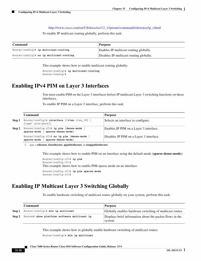
To enable IP multicast routing globally, perform this task:
This example shows how to enable multicast routing globally:
Router(config)# ip multicast-routingRouter(config)#
Enabling IPv4 PIM on Layer 3 Interfaces
You must enable PIM on the Layer 3 interfaces before IP multicast Layer 3 switching functions on those interfaces.
To enable IP PIM on a Layer 3 interface, perform this task:
This example shows how to enable PIM on an interface using the default mode (sparse-dense-mode):
Router(config-if)# ip pimRouter(config-if)#
This example shows how to enable PIM sparse mode on an interface:
Router(config-if)# ip pim sparse-modeRouter(config-if)#
Enabling IP Multicast Layer 3 Switching Globally
To enable hardware switching of multicast routes globally on your system, perform this task:
This example shows how to globally enable hardware switching of multicast routes:
Router(config)# mls ip multicast
Command Purpose
Router(config)# ip multicast-routing Enables IP multicast routing globally.
Router(config)# no ip multicast-routing Disables IP multicast routing globally.
Command Purpose
Step 1 Router(config)# interface {{vlan vlan_ID} | {type1 slot/port}}
1. type = ethernet, fastethernet, gigabitethernet, or tengigabitethernet
Selects an interface to configure.
Step 2 Router(config-if)# ip pim {dense-mode | sparse-mode | sparse-dense-mode}
Enables IP PIM on a Layer 3 interface.
Router(config-if)# no ip pim [dense-mode | sparse-mode | sparse-dense-mode]
Disables IP PIM on a Layer 3 interface.
Command Purpose
Step 1 Router(config)# mls ip multicast Globally enables hardware switching of multicast routes.
Step 2 Router# show platform software multicast ip Displays brief information about the packet flows in the system.
31-10Cisco 7600 Series Router Cisco IOS Software Configuration Guide, Release 15 S
OL-10113-33
Chapter 31 Configuring IPv4 Multicast Layer 3 Switching Configuring IPv4 Multicast Layer 3 Switching
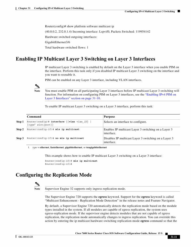
Router(config)# show platform software multicast ip
(40.0.0.2, 232.0.1.4) Incoming interface: Lspvif0, Packets Switched: 119954142
Hardware switched outgoing interfaces:
GigabitEthernet3/6
Total hardware switched flows: 1
Enabling IP Multicast Layer 3 Switching on Layer 3 Interfaces
IP multicast Layer 3 switching is enabled by default on the Layer 3 interface when you enable PIM on the interface. Perform this task only if you disabled IP multicast Layer 3 switching on the interface and you want to reenable it.
PIM can be enabled on any Layer 3 interface, including VLAN interfaces.
Note You must enable PIM on all participating Layer 3 interfaces before IP multicast Layer 3 switching will function. For information on configuring PIM on Layer 3 interfaces, see the “Enabling IPv4 PIM on Layer 3 Interfaces” section on page 31-10.
To enable IP multicast Layer 3 switching on a Layer 3 interface, perform this task:
This example shows how to enable IP multicast Layer 3 switching on a Layer 3 interface:
Router(config-if)# mls ip multicastRouter(config-if)#
Configuring the Replication Mode
Note Supervisor Engine 32 supports only ingress replication mode.
The Supervisor Engine 720 supports the egress keyword. Support for the egress keyword is called “Multicast Enhancement - Replication Mode Detection” in the release notes and Feature Navigator.
By default, a Supervisor Engine 720 automatically detects the replication mode based on the module types installed in the system. If all modules are capable of egress replication, the system uses egress-replication mode. If the supervisor engine detects modules that are not capable of egress replication, the replication mode automatically changes to ingress replication. You can override this action by entering the ip multicast hardware-switching replication-mode egress command so that the
Command Purpose
Step 1 Router(config)# interface {{vlan vlan_ID} | {type1 slot/port}}
1. type = ethernet, fastethernet, gigabitethernet, or tengigabitethernet
Selects an interface to configure.
Step 2 Router(config-if)# mls ip multicast Enables IP multicast Layer 3 switching on a Layer 3 interface.
Step 3 Router(config-if)# no mls ip multicast Disables IP multicast Layer 3 switching on a Layer 3 interface.
31-11Cisco 7600 Series Router Cisco IOS Software Configuration Guide, Release 15 S
OL-10113-33
Chapter 31 Configuring IPv4 Multicast Layer 3 Switching Configuring IPv4 Multicast Layer 3 Switching
system continues to work in egress-replication mode even if there are fabric-enabled modules installed that do not support egress replication (for example, OSMs). You can also configure the system to operate only in ingress-replication mode.
If the system is functioning in automatic detection mode, and you install a module that cannot perform egress replication, the following occurs:
• The system reverts to ingress mode
• A system log is generated
• A system reload occurs to revert to the old configuration
If the system is functioning in forced egress mode, a system log is created that will display the presence of modules that are not capable of egress replication mode.
Note If you configure forced egress mode in a system that has fabric-enabled modules that are not capable of egress replication, you must make sure that these modules are not sourcing or receiving multicast traffic.
During a change from egress- to ingress-replication mode, traffic interruptions may occur because the shortcuts will be purged and reinstalled. To avoid interruptions in traffic forwarding, enter the ip multicast hardware-switching replication-mode ingress command in global configuration mode. This command forces the system to operate in ingress-replication mode.
The no form of the ip multicast hardware-switching replication-mode ingress command restores the system to auomatic detection mode.
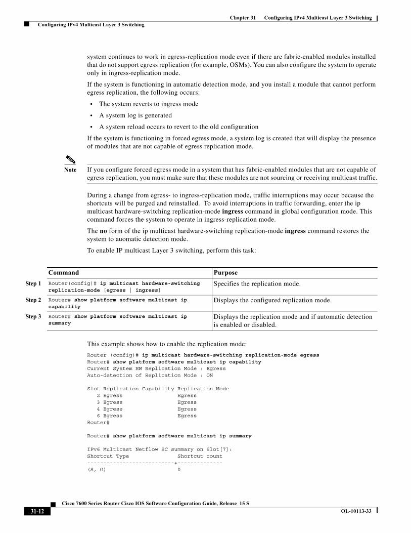
To enable IP multicast Layer 3 switching, perform this task:
This example shows how to enable the replication mode:
Router (config)# ip multicast hardware-switching replication-mode egressRouter# show platform software multicast ip capability Current System HW Replication Mode : EgressAuto-detection of Replication Mode : ON
Slot Replication-Capability Replication-Mode 2 Egress Egress 3 Egress Egress 4 Egress Egress 6 Egress Egress Router#
Router# show platform software multicast ip summary
IPv6 Multicast Netflow SC summary on Slot[7]:Shortcut Type Shortcut count---------------------------+--------------(S, G) 0
Command Purpose
Step 1 Router(config)# ip multicast hardware-switching replication-mode [egress | ingress]
Specifies the replication mode.
Step 2 Router# show platform software multicast ip capability
Displays the configured replication mode.
Step 3 Router# show platform software multicast ip summary
Displays the replication mode and if automatic detection is enabled or disabled.
31-12Cisco 7600 Series Router Cisco IOS Software Configuration Guide, Release 15 S
OL-10113-33
Chapter 31 Configuring IPv4 Multicast Layer 3 Switching Configuring IPv4 Multicast Layer 3 Switching
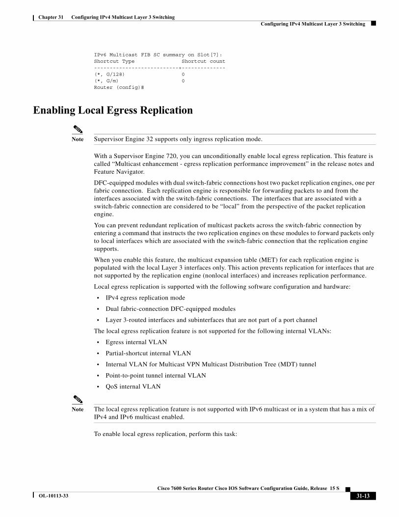
IPv6 Multicast FIB SC summary on Slot[7]:Shortcut Type Shortcut count---------------------------+--------------(*, G/128) 0(*, G/m) 0Router (config)#
Enabling Local Egress Replication
Note Supervisor Engine 32 supports only ingress replication mode.
With a Supervisor Engine 720, you can unconditionally enable local egress replication. This feature is called “Multicast enhancement - egress replication performance improvement” in the release notes and Feature Navigator.
DFC-equipped modules with dual switch-fabric connections host two packet replication engines, one per fabric connection. Each replication engine is responsible for forwarding packets to and from the interfaces associated with the switch-fabric connections. The interfaces that are associated with a switch-fabric connection are considered to be “local” from the perspective of the packet replication engine.
You can prevent redundant replication of multicast packets across the switch-fabric connection by entering a command that instructs the two replication engines on these modules to forward packets only to local interfaces which are associated with the switch-fabric connection that the replication engine supports.
When you enable this feature, the multicast expansion table (MET) for each replication engine is populated with the local Layer 3 interfaces only. This action prevents replication for interfaces that are not supported by the replication engine (nonlocal interfaces) and increases replication performance.
Local egress replication is supported with the following software configuration and hardware:
• IPv4 egress replication mode
• Dual fabric-connection DFC-equipped modules
• Layer 3-routed interfaces and subinterfaces that are not part of a port channel
The local egress replication feature is not supported for the following internal VLANs:
• Egress internal VLAN
• Partial-shortcut internal VLAN
• Internal VLAN for Multicast VPN Multicast Distribution Tree (MDT) tunnel
• Point-to-point tunnel internal VLAN
• QoS internal VLAN
Note The local egress replication feature is not supported with IPv6 multicast or in a system that has a mix of IPv4 and IPv6 multicast enabled.
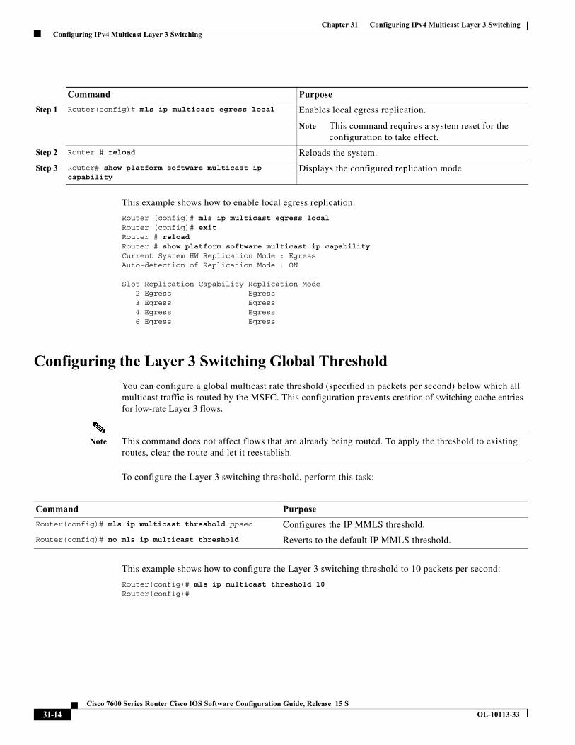
To enable local egress replication, perform this task:
31-13Cisco 7600 Series Router Cisco IOS Software Configuration Guide, Release 15 S
OL-10113-33
Chapter 31 Configuring IPv4 Multicast Layer 3 Switching Configuring IPv4 Multicast Layer 3 Switching
This example shows how to enable local egress replication:
Router (config)# mls ip multicast egress local Router (config)# exit Router # reload Router # show platform software multicast ip capabilityCurrent System HW Replication Mode : EgressAuto-detection of Replication Mode : ON
Slot Replication-Capability Replication-Mode 2 Egress Egress 3 Egress Egress 4 Egress Egress 6 Egress Egress
Configuring the Layer 3 Switching Global Threshold
You can configure a global multicast rate threshold (specified in packets per second) below which all multicast traffic is routed by the MSFC. This configuration prevents creation of switching cache entries for low-rate Layer 3 flows.
Note This command does not affect flows that are already being routed. To apply the threshold to existing routes, clear the route and let it reestablish.
To configure the Layer 3 switching threshold, perform this task:
This example shows how to configure the Layer 3 switching threshold to 10 packets per second:
Router(config)# mls ip multicast threshold 10 Router(config)#
Command Purpose
Step 1 Router(config)# mls ip multicast egress local Enables local egress replication.
Note This command requires a system reset for the configuration to take effect.
Step 2 Router # reload Reloads the system.
Step 3 Router# show platform software multicast ip capability
Displays the configured replication mode.
Command Purpose
Router(config)# mls ip multicast threshold ppsec Configures the IP MMLS threshold.
Router(config)# no mls ip multicast threshold Reverts to the default IP MMLS threshold.
31-14Cisco 7600 Series Router Cisco IOS Software Configuration Guide, Release 15 S
OL-10113-33
Chapter 31 Configuring IPv4 Multicast Layer 3 Switching Configuring IPv4 Multicast Layer 3 Switching
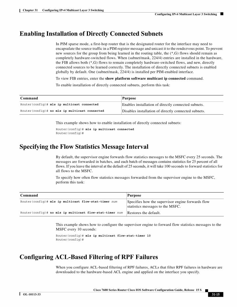
Enabling Installation of Directly Connected Subnets
In PIM sparse mode, a first-hop router that is the designated router for the interface may need to encapsulate the source traffic in a PIM register message and unicast it to the rendezvous point. To prevent new sources for the group from being learned in the routing table, the (*,G) flows should remain as completely hardware-switched flows. When (subnet/mask, 224/4) entries are installed in the hardware, the FIB allows both (*,G) flows to remain completely hardware-switched flows, and new, directly connected sources to be learned correctly. The installation of directly connected subnets is enabled globally by default. One (subnet/mask, 224/4) is installed per PIM-enabled interface.
To view FIB entries, enter the show platform software multicast ip connected command.
To enable installation of directly connected subnets, perform this task:
This example shows how to enable installation of directly connected subnets:
Router(config)# mls ip multicast connected Router(config)#
Specifying the Flow Statistics Message Interval
By default, the supervisor engine forwards flow statistics messages to the MSFC every 25 seconds. The messages are forwarded in batches, and each batch of messages contains statistics for 25 percent of all flows. If you leave the interval at the default of 25 seconds, it will take 100 seconds to forward statistics for all flows to the MSFC.
To specify how often flow statistics messages forwarded from the supervisor engine to the MSFC, perform this task:
This example shows how to configure the supervisor engine to forward flow statistics messages to the MSFC every 10 seconds:
Router(config)# mls ip multicast flow-stat-timer 10 Router(config)#
Configuring ACL-Based Filtering of RPF Failures
When you configure ACL-based filtering of RPF failures, ACLs that filter RPF failures in hardware are downloaded to the hardware-based ACL engine and applied on the interface you specify.
Command Purpose
Router(config)# mls ip multicast connected Enables installation of directly connected subnets.
Router(config)# no mls ip multicast connected Disables installation of directly connected subnets.
Command Purpose
Router(config)# mls ip multicast flow-stat-timer num Specifies how the supervisor engine forwards flow statistics messages to the MSFC.
Router(config)# no mls ip multicast flow-stat-timer num Restores the default.
31-15Cisco 7600 Series Router Cisco IOS Software Configuration Guide, Release 15 S
OL-10113-33
Chapter 31 Configuring IPv4 Multicast Layer 3 Switching Configuring IPv4 Multicast Layer 3 Switching
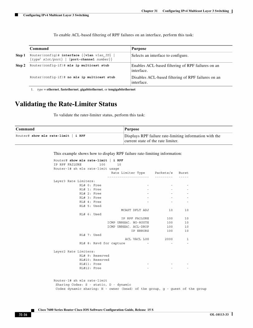
To enable ACL-based filtering of RPF failures on an interface, perform this task:
Validating the Rate-Limiter Status
To validate the rater-limiter status, perform this task:
This example shows how to display RPF failure rate-limiting information:
Router# show mls rate-limit | i RPFIP RPF FAILURE 100 10Router-1# sh mls rate-limit usage Rate Limiter Type Packets/s Burst --------------------- --------- -----Layer3 Rate Limiters: RL# 0: Free - - - RL# 1: Free - - - RL# 2: Free - - - RL# 3: Free - - - RL# 4: Free - - - RL# 5: Used MCAST DFLT ADJ 10 10 RL# 6: Used IP RPF FAILURE 100 10 ICMP UNREAC. NO-ROUTE 100 10 ICMP UNREAC. ACL-DROP 100 10 IP ERRORS 100 10 RL# 7: Used ACL VACL LOG 2000 1 RL# 8: Rsvd for capture - - - Layer2 Rate Limiters: RL# 9: Reserved RL#10: Reserved RL#11: Free - - - RL#12: Free - - -
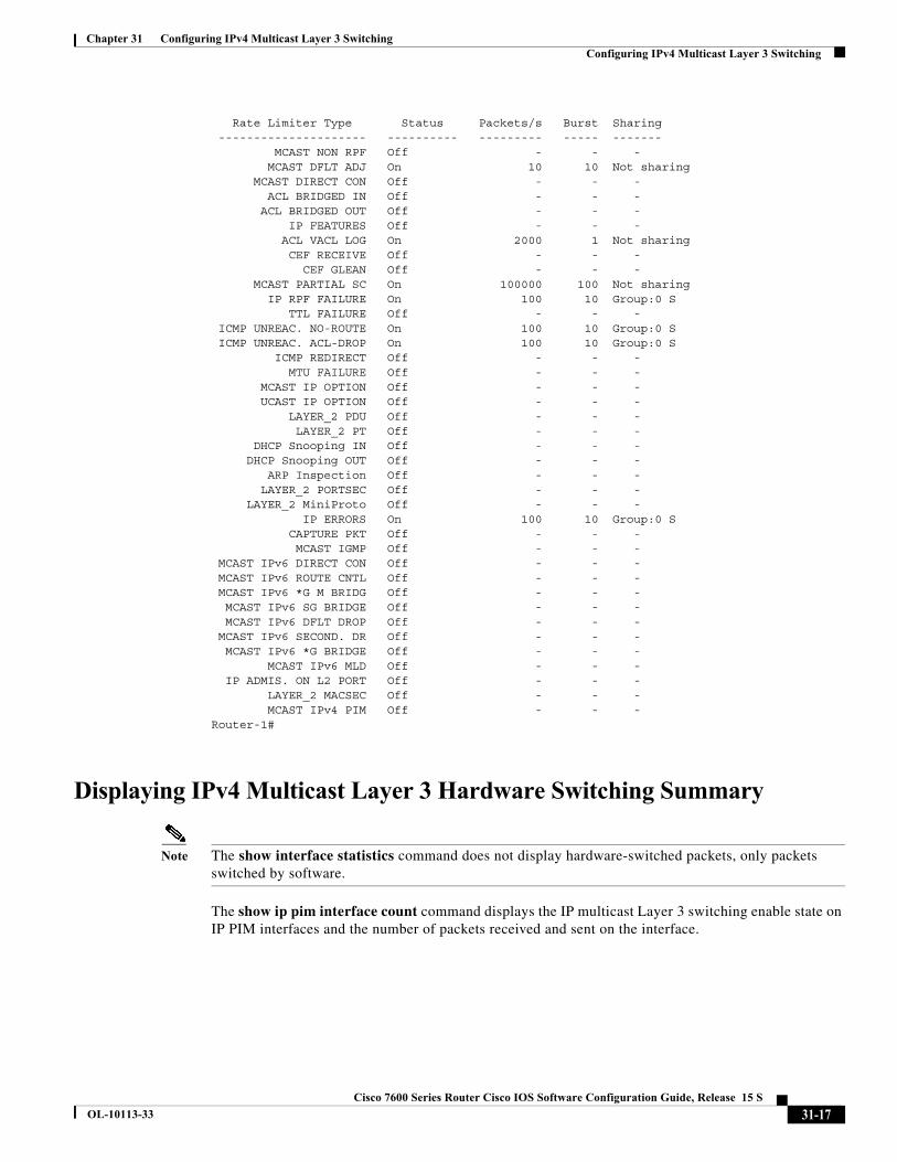
Router-1# sh mls rate-limit Sharing Codes: S - static, D - dynamic Codes dynamic sharing: H - owner (head) of the group, g - guest of the group
Command Purpose
Step 1 Router(config)# interface {{vlan vlan_ID} | {type1 slot/port} | {port-channel number}}
1. type = ethernet, fastethernet, gigabitethernet, or tengigabitethernet
Selects an interface to configure.
Step 2 Router(config-if)# mls ip multicast stub Enables ACL-based filtering of RPF failures on an interface.
Router(config-if)# no mls ip multicast stub Disables ACL-based filtering of RPF failures on an interface.
Command Purpose
Router# show mls rate-limit | i RPF Displays RPF failure rate-limiting information with the current state of the rate limiter.
31-16Cisco 7600 Series Router Cisco IOS Software Configuration Guide, Release 15 S
OL-10113-33
Chapter 31 Configuring IPv4 Multicast Layer 3 Switching Configuring IPv4 Multicast Layer 3 Switching
Rate Limiter Type Status Packets/s Burst Sharing --------------------- ---------- --------- ----- ------- MCAST NON RPF Off - - - MCAST DFLT ADJ On 10 10 Not sharing MCAST DIRECT CON Off - - - ACL BRIDGED IN Off - - - ACL BRIDGED OUT Off - - - IP FEATURES Off - - - ACL VACL LOG On 2000 1 Not sharing CEF RECEIVE Off - - - CEF GLEAN Off - - - MCAST PARTIAL SC On 100000 100 Not sharing IP RPF FAILURE On 100 10 Group:0 S TTL FAILURE Off - - - ICMP UNREAC. NO-ROUTE On 100 10 Group:0 S ICMP UNREAC. ACL-DROP On 100 10 Group:0 S ICMP REDIRECT Off - - - MTU FAILURE Off - - - MCAST IP OPTION Off - - - UCAST IP OPTION Off - - - LAYER_2 PDU Off - - - LAYER_2 PT Off - - - DHCP Snooping IN Off - - - DHCP Snooping OUT Off - - - ARP Inspection Off - - - LAYER_2 PORTSEC Off - - - LAYER_2 MiniProto Off - - - IP ERRORS On 100 10 Group:0 S CAPTURE PKT Off - - - MCAST IGMP Off - - - MCAST IPv6 DIRECT CON Off - - - MCAST IPv6 ROUTE CNTL Off - - - MCAST IPv6 *G M BRIDG Off - - - MCAST IPv6 SG BRIDGE Off - - - MCAST IPv6 DFLT DROP Off - - - MCAST IPv6 SECOND. DR Off - - - MCAST IPv6 *G BRIDGE Off - - - MCAST IPv6 MLD Off - - - IP ADMIS. ON L2 PORT Off - - - LAYER_2 MACSEC Off - - - MCAST IPv4 PIM Off - - -Router-1#
Displaying IPv4 Multicast Layer 3 Hardware Switching Summary
Note The show interface statistics command does not display hardware-switched packets, only packets switched by software.
The show ip pim interface count command displays the IP multicast Layer 3 switching enable state on IP PIM interfaces and the number of packets received and sent on the interface.
31-17Cisco 7600 Series Router Cisco IOS Software Configuration Guide, Release 15 S
OL-10113-33

Chapter 31 Configuring IPv4 Multicast Layer 3 Switching Configuring IPv4 Multicast Layer 3 Switching
To display IP multicast Layer 3 switching information for an IP PIM Layer 3 interface, perform one of these tasks:
These examples show how to display the IP PIM configuration of the interfaces:
Router# show ip pim interface count
State:* - Fast Switched, D - Distributed Fast SwitchedH - Hardware Switching Enabled
Address Interface FS Mpackets In/Out10.15.1.20 GigabitEthernet4/8 * H 952/423713077010.20.1.7 GigabitEthernet4/9 * H 1385673757/3410.25.1.7 GigabitEthernet4/10* H 0/3410.11.1.30 FastEthernet6/26 * H 0/010.37.1.1 FastEthernet6/37 * H 0/01.22.33.44 FastEthernet6/47 * H 514/68
The “*” flag indicates that this interface can be fast switched and the “H” flag indicates that this interface is hardware switched. The “In” flag indicates the number of multicast packet bytes that have been received on the interface. The “Out” flag indicates the number of multicast packet bytes that have been forwarded from this interface.
Router# show ip mroute count IP Multicast Statistics56 routes using 28552 bytes of memory13 groups, 3.30 average sources per groupForwarding Counts:Pkt Count/Pkts per second/Avg Pkt Size/Kilobits per secondOther counts:Total/RPF failed/Other drops(OIF-null, rate-limit etc) Group:224.2.136.89, Source count:1, Group pkt count:29051 Source:132.206.72.28/32, Forwarding:29051/-278/1186/0, Other:85724/8/56665Router#
Note The -tive counter means that the outgoing interface list of the corresponding entry is NULL, and this indicates that this flow is still active.
This example shows how to display the IP multicast Layer 3 switching configuration of interface VLAN 10:
Router# show ip interface vlan 10 Vlan10 is up, line protocol is up Internet address is 10.0.0.6/8 Broadcast address is 255.255.255.255 Address determined by non-volatile memory MTU is 1500 bytes Helper address is not set Directed broadcast forwarding is disabled Multicast reserved groups joined: 224.0.0.1 224.0.0.2 224.0.0.13 224.0.0.10 Outgoing access list is not set Inbound access list is not set
Command Purpose
Router# show ip pim interface [{{vlan vlan_ID} | {type1 slot/port} | {port-channel number}}] count
1. type = ethernet, fastethernet, gigabitethernet, or tengigabitethernet
Displays IP multicast Layer 3 switching enable state information for all MSFC IP PIM Layer 3 interfaces.
Router# show ip interface Displays the IP multicast Layer 3 switching enable state on the Layer 3 interfaces.
31-18Cisco 7600 Series Router Cisco IOS Software Configuration Guide, Release 15 S
OL-10113-33
Chapter 31 Configuring IPv4 Multicast Layer 3 Switching Configuring IPv4 Multicast Layer 3 Switching
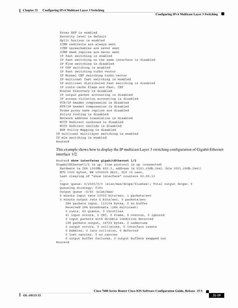
Proxy ARP is enabled Security level is default Split horizon is enabled ICMP redirects are always sent ICMP unreachables are never sent ICMP mask replies are never sent IP fast switching is enabled IP fast switching on the same interface is disabled IP Flow switching is disabled IP CEF switching is enabled IP Fast switching turbo vector IP Normal CEF switching turbo vector IP multicast fast switching is enabled IP multicast distributed fast switching is disabled IP route-cache flags are Fast, CEF Router Discovery is disabled IP output packet accounting is disabled IP access violation accounting is disabled TCP/IP header compression is disabled RTP/IP header compression is disabled Probe proxy name replies are disabled Policy routing is disabled Network address translation is disabled WCCP Redirect outbound is disabled WCCP Redirect exclude is disabled BGP Policy Mapping is disabledIP multicast multilayer switching is enabledIP mls switching is enabledRouter#
This example shows how to display the IP multicast Layer 3 switching configuration of Gigabit Ethernet interface 1/2:
Router# show interfaces gigabitEthernet 1/2 GigabitEthernet1/2 is up, line protocol is up (connected) Hardware is C6k 1000Mb 802.3, address is 0001.c9db.2441 (bia 0001.c9db.2441) MTU 1500 bytes, BW 1000000 Kbit, DLY 10 usec, Last clearing of "show interface" counters 00:05:13 …. Input queue: 0/2000/0/0 (size/max/drops/flushes); Total output drops: 0 Queueing strategy: fifo Output queue :0/40 (size/max) 5 minute input rate 10000 bits/sec, 1 packets/sec 5 minute output rate 0 bits/sec, 0 packets/sec 284 packets input, 113104 bytes, 0 no buffer Received 284 broadcasts (284 multicast) 0 runts, 41 giants, 0 throttles 41 input errors, 0 CRC, 0 frame, 0 overrun, 0 ignored 0 input packets with dribble condition detected 198 packets output, 14732 bytes, 0 underruns 0 output errors, 0 collisions, 0 interface resets 0 babbles, 0 late collision, 0 deferred 0 lost carrier, 0 no carrier 0 output buffer failures, 0 output buffers swapped outRouter#
31-19Cisco 7600 Series Router Cisco IOS Software Configuration Guide, Release 15 S
OL-10113-33
Chapter 31 Configuring IPv4 Multicast Layer 3 Switching Configuring IPv4 Multicast Layer 3 Switching
Displaying the IPv4 Multicast Routing Table
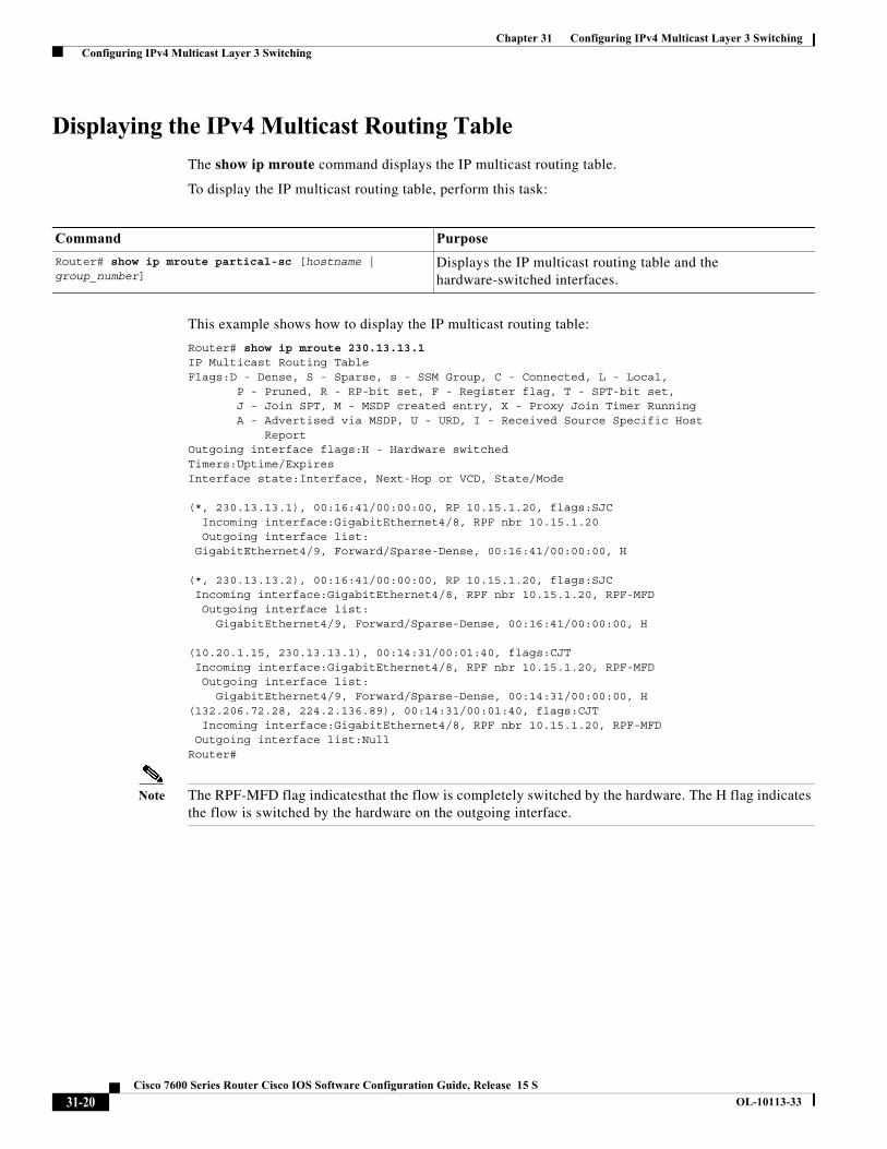
The show ip mroute command displays the IP multicast routing table.
To display the IP multicast routing table, perform this task:
This example shows how to display the IP multicast routing table:
Router# show ip mroute 230.13.13.1 IP Multicast Routing TableFlags:D - Dense, S - Sparse, s - SSM Group, C - Connected, L - Local, P - Pruned, R - RP-bit set, F - Register flag, T - SPT-bit set, J - Join SPT, M - MSDP created entry, X - Proxy Join Timer Running A - Advertised via MSDP, U - URD, I - Received Source Specific Host Report Outgoing interface flags:H - Hardware switchedTimers:Uptime/ExpiresInterface state:Interface, Next-Hop or VCD, State/Mode (*, 230.13.13.1), 00:16:41/00:00:00, RP 10.15.1.20, flags:SJC Incoming interface:GigabitEthernet4/8, RPF nbr 10.15.1.20 Outgoing interface list: GigabitEthernet4/9, Forward/Sparse-Dense, 00:16:41/00:00:00, H
(*, 230.13.13.2), 00:16:41/00:00:00, RP 10.15.1.20, flags:SJC Incoming interface:GigabitEthernet4/8, RPF nbr 10.15.1.20, RPF-MFD Outgoing interface list: GigabitEthernet4/9, Forward/Sparse-Dense, 00:16:41/00:00:00, H (10.20.1.15, 230.13.13.1), 00:14:31/00:01:40, flags:CJT Incoming interface:GigabitEthernet4/8, RPF nbr 10.15.1.20, RPF-MFD Outgoing interface list: GigabitEthernet4/9, Forward/Sparse-Dense, 00:14:31/00:00:00, H(132.206.72.28, 224.2.136.89), 00:14:31/00:01:40, flags:CJT Incoming interface:GigabitEthernet4/8, RPF nbr 10.15.1.20, RPF-MFD Outgoing interface list:NullRouter#
Note The RPF-MFD flag indicatesthat the flow is completely switched by the hardware. The H flag indicates the flow is switched by the hardware on the outgoing interface.
Command Purpose
Router# show ip mroute partical-sc [hostname | group_number]
Displays the IP multicast routing table and the hardware-switched interfaces.
31-20Cisco 7600 Series Router Cisco IOS Software Configuration Guide, Release 15 S
OL-10113-33
Chapter 31 Configuring IPv4 Multicast Layer 3 Switching Configuring IPv4 Multicast Layer 3 Switching
Displaying IPv4 Multicast Layer 3 Switching Statistics
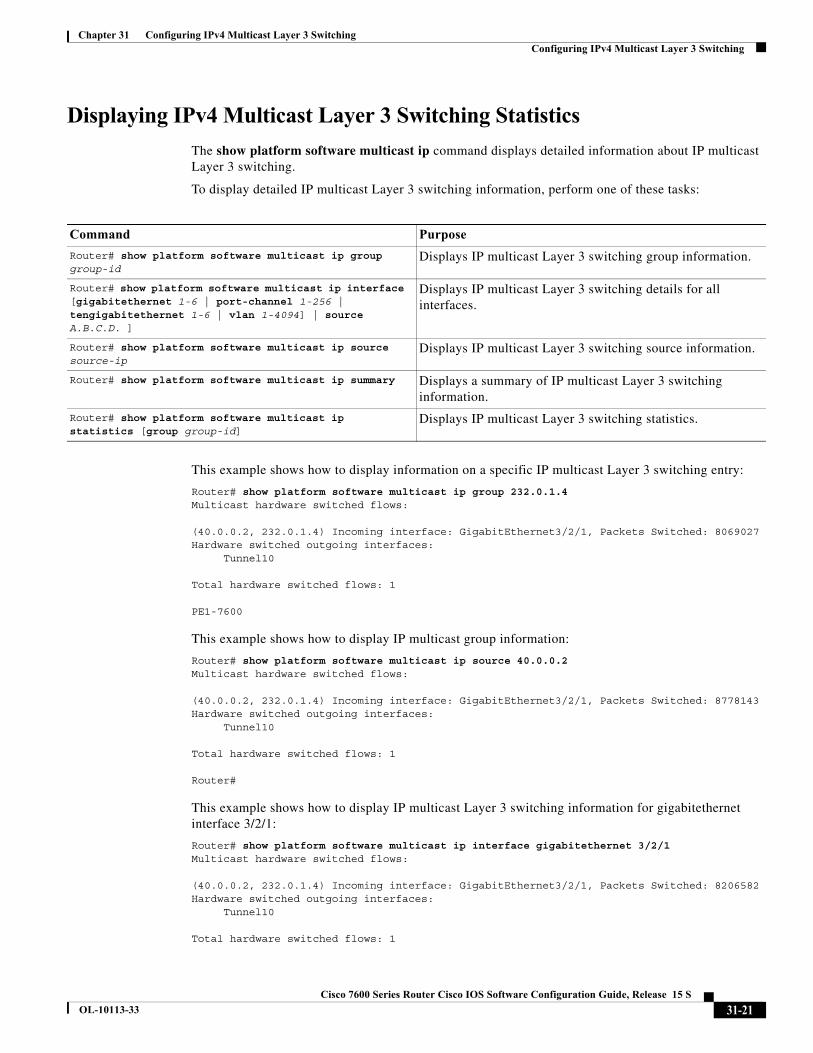
The show platform software multicast ip command displays detailed information about IP multicast Layer 3 switching.
To display detailed IP multicast Layer 3 switching information, perform one of these tasks:
This example shows how to display information on a specific IP multicast Layer 3 switching entry:
Router# show platform software multicast ip group 232.0.1.4Multicast hardware switched flows:
(40.0.0.2, 232.0.1.4) Incoming interface: GigabitEthernet3/2/1, Packets Switched: 8069027Hardware switched outgoing interfaces: Tunnel10 Total hardware switched flows: 1
PE1-7600
This example shows how to display IP multicast group information:
Router# show platform software multicast ip source 40.0.0.2Multicast hardware switched flows:
(40.0.0.2, 232.0.1.4) Incoming interface: GigabitEthernet3/2/1, Packets Switched: 8778143Hardware switched outgoing interfaces: Tunnel10 Total hardware switched flows: 1
Router#
This example shows how to display IP multicast Layer 3 switching information for gigabitethernet interface 3/2/1:
Router# show platform software multicast ip interface gigabitethernet 3/2/1Multicast hardware switched flows:
(40.0.0.2, 232.0.1.4) Incoming interface: GigabitEthernet3/2/1, Packets Switched: 8206582Hardware switched outgoing interfaces: Tunnel10 Total hardware switched flows: 1
Command Purpose
Router# show platform software multicast ip group group-id
Displays IP multicast Layer 3 switching group information.
Router# show platform software multicast ip interface [gigabitethernet 1-6 | port-channel 1-256 | tengigabitethernet 1-6 | vlan 1-4094] | source A.B.C.D. ]
Displays IP multicast Layer 3 switching details for all interfaces.
Router# show platform software multicast ip source source-ip
Displays IP multicast Layer 3 switching source information.
Router# show platform software multicast ip summary Displays a summary of IP multicast Layer 3 switching information.
Router# show platform software multicast ip statistics [group group-id]
Displays IP multicast Layer 3 switching statistics.
31-21Cisco 7600 Series Router Cisco IOS Software Configuration Guide, Release 15 S
OL-10113-33
Chapter 31 Configuring IPv4 Multicast Layer 3 Switching Configuring IPv4 Bidirectional PIM
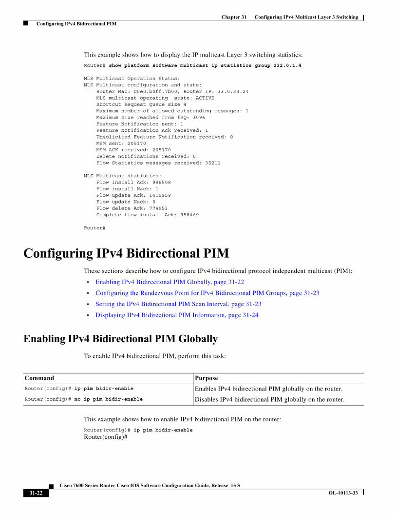
This example shows how to display the IP multicast Layer 3 switching statistics:
Router# show platform software multicast ip statistics group 232.0.1.4 MLS Multicast Operation Status:MLS Multicast configuration and state: Router Mac: 00e0.b0ff.7b00, Router IP: 33.0.33.24 MLS multicast operating state: ACTIVE Shortcut Request Queue size 4 Maximum number of allowed outstanding messages: 1 Maximum size reached from feQ: 3096 Feature Notification sent: 1 Feature Notification Ack received: 1 Unsolicited Feature Notification received: 0 MSM sent: 205170 MSM ACK received: 205170 Delete notifications received: 0 Flow Statistics messages received: 35211 MLS Multicast statistics: Flow install Ack: 996508 Flow install Nack: 1 Flow update Ack: 1415959 Flow update Nack: 0 Flow delete Ack: 774953 Complete flow install Ack: 958469 Router#
Configuring IPv4 Bidirectional PIMThese sections describe how to configure IPv4 bidirectional protocol independent multicast (PIM):
• Enabling IPv4 Bidirectional PIM Globally, page 31-22
• Configuring the Rendezvous Point for IPv4 Bidirectional PIM Groups, page 31-23
• Setting the IPv4 Bidirectional PIM Scan Interval, page 31-23
• Displaying IPv4 Bidirectional PIM Information, page 31-24
Enabling IPv4 Bidirectional PIM Globally
To enable IPv4 bidirectional PIM, perform this task:
This example shows how to enable IPv4 bidirectional PIM on the router:
Router(config)# ip pim bidir-enable
Router(config)#
Command Purpose
Router(config)# ip pim bidir-enable Enables IPv4 bidirectional PIM globally on the router.
Router(config)# no ip pim bidir-enable Disables IPv4 bidirectional PIM globally on the router.
31-22Cisco 7600 Series Router Cisco IOS Software Configuration Guide, Release 15 S
OL-10113-33
Chapter 31 Configuring IPv4 Multicast Layer 3 Switching Configuring IPv4 Bidirectional PIM
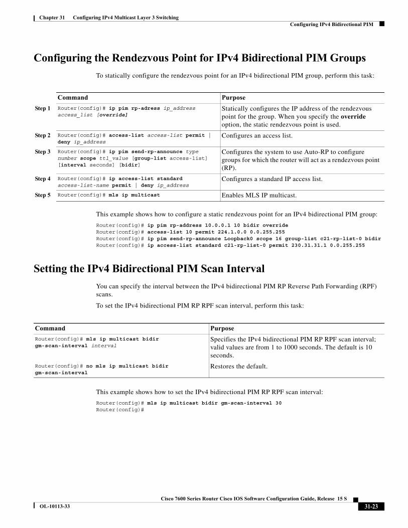
Configuring the Rendezvous Point for IPv4 Bidirectional PIM Groups
To statically configure the rendezvous point for an IPv4 bidirectional PIM group, perform this task:
This example shows how to configure a static rendezvous point for an IPv4 bidirectional PIM group:
Router(config)# ip pim rp-address 10.0.0.1 10 bidir override Router(config)# access-list 10 permit 224.1.0.0 0.0.255.255 Router(config)# ip pim send-rp-announce Loopback0 scope 16 group-list c21-rp-list-0 bidir Router(config)# ip access-list standard c21-rp-list-0 permit 230.31.31.1 0.0.255.255
Setting the IPv4 Bidirectional PIM Scan Interval
You can specify the interval between the IPv4 bidirectional PIM RP Reverse Path Forwarding (RPF) scans.
To set the IPv4 bidirectional PIM RP RPF scan interval, perform this task:
This example shows how to set the IPv4 bidirectional PIM RP RPF scan interval:
Router(config)# mls ip multicast bidir gm-scan-interval 30Router(config)#
Command Purpose
Step 1 Router(config)# ip pim rp-adress ip_address access_list [override]
Statically configures the IP address of the rendezvous point for the group. When you specify the override option, the static rendezvous point is used.
Step 2 Router(config)# access-list access-list permit | deny ip_address
Configures an access list.
Step 3 Router(config)# ip pim send-rp-announce type number scope ttl_value [group-list access-list] [interval seconds] [bidir]
Configures the system to use Auto-RP to configure groups for which the router will act as a rendezvous point (RP).
Step 4 Router(config)# ip access-list standard access-list-name permit | deny ip_address
Configures a standard IP access list.
Step 5 Router(config)# mls ip multicast Enables MLS IP multicast.
Command Purpose
Router(config)# mls ip multicast bidir gm-scan-interval interval
Specifies the IPv4 bidirectional PIM RP RPF scan interval; valid values are from 1 to 1000 seconds. The default is 10 seconds.
Router(config)# no mls ip multicast bidir gm-scan-interval
Restores the default.
31-23Cisco 7600 Series Router Cisco IOS Software Configuration Guide, Release 15 S
OL-10113-33
Chapter 31 Configuring IPv4 Multicast Layer 3 Switching Configuring IPv4 Bidirectional PIM
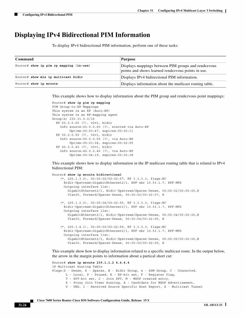
Displaying IPv4 Bidirectional PIM Information
To display IPv4 bidirectional PIM information, perform one of these tasks:
This example shows how to display information about the PIM group and rendezvous point mappings:
Router# show ip pim rp mapping PIM Group-to-RP MappingsThis system is an RP (Auto-RP)This system is an RP-mapping agentGroup(s) 230.31.0.0/16 RP 60.0.0.60 (?), v2v1, bidir Info source:60.0.0.60 (?), elected via Auto-RP Uptime:00:03:47, expires:00:02:11 RP 50.0.0.50 (?), v2v1, bidir Info source:50.0.0.50 (?), via Auto-RP Uptime:00:03:04, expires:00:02:55 RP 40.0.0.40 (?), v2v1, bidir Info source:40.0.0.40 (?), via Auto-RP Uptime:00:04:19, expires:00:02:38
This example shows how to display information in the IP multicast routing table that is related to IPv4 bidirectional PIM:
Router# show ip mroute bidirectional (*, 225.1.3.0), 00:00:02/00:02:57, RP 3.3.3.3, flags:BC Bidir-Upstream:GigabitEthernet2/1, RPF nbr 10.53.1.7, RPF-MFD Outgoing interface list: GigabitEthernet2/1, Bidir-Upstream/Sparse-Dense, 00:00:02/00:00:00,H Vlan30, Forward/Sparse-Dense, 00:00:02/00:02:57, H
(*, 225.1.2.0), 00:00:04/00:02:55, RP 3.3.3.3, flags:BC Bidir-Upstream:GigabitEthernet2/1, RPF nbr 10.53.1.7, RPF-MFD Outgoing interface list: GigabitEthernet2/1, Bidir-Upstream/Sparse-Dense, 00:00:04/00:00:00,H Vlan30, Forward/Sparse-Dense, 00:00:04/00:02:55, H
(*, 225.1.4.1), 00:00:00/00:02:59, RP 3.3.3.3, flags:BC Bidir-Upstream:GigabitEthernet2/1, RPF nbr 10.53.1.7, RPF-MFD Outgoing interface list: GigabitEthernet2/1, Bidir-Upstream/Sparse-Dense, 00:00:00/00:00:00,H Vlan30, Forward/Sparse-Dense, 00:00:00/00:02:59, H
This example show how to display information related to a specific multicast route. In the output below, the arrow in the margin points to information about a partical short cut:
Router# show ip mroute 239.1.1.2 4.4.4.4 IP Multicast Routing TableFlags:D - Dense, S - Sparse, B - Bidir Group, s - SSM Group, C - Connected, L - Local, P - Pruned, R - RP-bit set, F - Register flag, T - SPT-bit set, J - Join SPT, M - MSDP created entry, X - Proxy Join Timer Running, A - Candidate for MSDP Advertisement, U - URD, I - Received Source Specific Host Report, Z - Multicast Tunnel
Command Purpose
Router# show ip pim rp mapping [in-use] Displays mappings between PIM groups and rendezvous points and shows learned rendezvous points in use.
Router# show mls ip multicast bidir Displays IPv4 bidirectional PIM information.
Router# show ip mroute Displays information about the mutlicast routing table.
31-24Cisco 7600 Series Router Cisco IOS Software Configuration Guide, Release 15 S
OL-10113-33
Chapter 31 Configuring IPv4 Multicast Layer 3 Switching Configuring IPv4 Bidirectional PIM
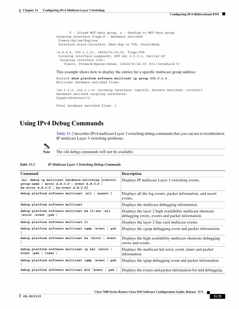
Y - Joined MDT-data group, y - Sending to MDT-data groupOutgoing interface flags:H - Hardware switched Timers:Uptime/Expires Interface state:Interface, Next-Hop or VCD, State/Mode
(4.4.4.4, 239.1.1.2), 1d02h/00:03:20, flags:FTZ Incoming interface:Loopback0, RPF nbr 0.0.0.0, Partial-SC Outgoing interface list: Vlan10, Forward/Sparse-Dense, 1d02h/00:02:39 (ttl-threshold 5)
This example shows how to display the entries for a specific multicast group address:
Router# show platform software multicast ip group 232.0.1.4Multicast hardware switched flows:
(40.0.0.2, 232.0.1.4) Incoming interface: Lspvif0, Packets Switched: 120181613Hardware switched outgoing interfaces:GigabitEthernet3/6
Total hardware switched flows: 1
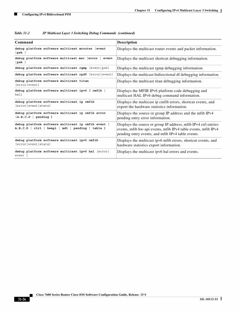
Using IPv4 Debug Commands
Table 31-2 describes IPv4 multicast Layer 3 switching debug commands that you can use to troubleshoot IP multicast Layer 3 switching problems.
Note The old debug commands will not be available.
Table 31-2 IP Multicast Layer 3 Switching Debug Commands
Command Description
[no] debug ip multicast hardware-switching {control group-name | error A.B.C.D | event A.B.C.D | ha-error A.B.C.D | ha-event A.B.C.D}
Displays IP multicast Layer 3 switching events.
debug platform software multicast [all | assert ] Displays all the log events, packet information, and assert events.
debug platform software multicast Displays the multicast debugging information.
debug platform software multicast ha l2-sso [all |error |event |pak ]
Displays the layer 2 high availability multicast shortcuts debugging errors, events and packet information.
debug platform software multicast lc Displays the layer 2 line card multicast events.
debug platform software multicast cgmp [event | pak ]
Displays the cgmp debugging event and packet information.
debug platform software multicast ha [error | event ]
Displays the high availability multicast shortcuts debugging errors and events.
debug platform software multicast ip hal [error | event |pak | timer ]
Displays the multicast hal error, event, timer and packet information.
debug platform software multicast igmp [event | pak ]
Displays the igmp debugging event and packet information.
debug platform software multicast mld [event | pak ] Displays the events and packet information for mld debugging.
31-25Cisco 7600 Series Router Cisco IOS Software Configuration Guide, Release 15 S
OL-10113-33
Chapter 31 Configuring IPv4 Multicast Layer 3 Switching Configuring IPv4 Bidirectional PIM
debug platform software multicast mrouter [event |pak ]
Displays the multicast router events and packet information.
debug platform software multicast msc [error | event |pak ]
Displays the multicast shortcut debugging information.
debug platform software multicast rgmp [event|pak] Displays the multicast rgmp debugging information.
debug platform software multicast rpdf [error|event] Displays the multicast bidirectional df debugging information.
debug platform software multicast titan [error|event]
Displays the multicast titan debugging information.
debug platform software multicast ipv6 [ cmfib | hal]
Displays the MFIB IPv6 platform code debugging and multicast HAL IPv6 debug command information.
debug platform software multicast ip cmfib [error|event|stats]
Displays the multicast ip cmfib errors, shortcut events, and export the hardware statistics information.
debug platform software multicast ip cmfib error [A.B.C.D | pending ]
Displays the source or group IP address and the mfib IPv4 pending entry error information.
debug platform software multicast ip cmfib event [ A.B.C.D | ctrl | hwapi | mdt | pending | table ]
Displays the source or group IP address, mfib IPv4 ctrl entries events, mfib hw-api events, mfib IPv4 table events, mfib IPv4 pending entry events, and mfib IPv4 table events.
debug platform software multicast ipv6 cmfib [error|event|stats]
Displays the multicast ipv6 mfib errors, shortcut events, and hardware statistics export information.
debug platform software multicast ipv6 hal [error| event ]
Displays the multicast ipv6 hal errors and events.
Table 31-2 IP Multicast Layer 3 Switching Debug Commands (continued)
Command Description
31-26Cisco 7600 Series Router Cisco IOS Software Configuration Guide, Release 15 S
OL-10113-33