configuring data centers to support hp bladesystem p-class
TRANSCRIPT

1 ____________________________________________________________________________________________________ 2005 American Power Conversion. All rights reserved. No part of this publication may be used, reproduced, photocopied, transmitted, or stored in any retrieval system of any nature, without the written permission of the copyright owner. www.apc.com Rev 2005-0
Abstract HP BladeSystem p-Class servers operate at a power density 10X higher than that of a typical data center, which demands
special attention to the power and cooling system. Success in deploying these servers – there are five basic strategies –
requires an understanding of several inputs, including the business needs driving the deployment, user preferences, blade
requirements, and constraints. This Application Note considers these inputs, and guides the reader to:
• Select the best deployment method from the five basic methods
• Choose the appropriate rack, cooling, power, and management solutions
• Apply these solutions to fit individual needs
Needs Assessment HP BladeSystem p-Class servers have environmental requirements that exceed those of traditional rack mounted servers, and
can overload their environment if not properly integrated. Therefore, it is important that the IT manager take the time to
conduct a needs assessment to understand the business needs and preferences and identify facility constraints. This is
particularly important if the blade servers are to be deployed in an existing data center. Key needs, preferences, and
constraints are listed below, and explained in further detail in APC White Paper #125, “Strategies for Deploying Blade Servers
in Existing Data Centers”.
Business requirements and user preferences include:
• Existing data center uninterrupted operation – Is scheduled maintenance downtime a possibility?
• High availability of resulting system – Are redundant power and cooling required?
• Dense pack; co-location of servers – Do the blade servers need to remain in a specific area or can they be
spread out?
• Preparation for follow-on deployments – Is this blade server deployment going to be phased?
• Time – Are there any time constraints to the deployment?
• Cost – Are there budget constraints?
APC APPLICATION NOTE #75 Configuring Data Centers to Support HP
BladeSystem™ p-Class Servers
By Jim Spitaels

2 ___________________________________________________________________________________________________ 2005 American Power Conversion. All rights reserved. No part of this publication may be used, reproduced, photocopied, transmitted, or stored in any retrieval system of any nature, without the written permission of the copyright owner. www.apc.com Rev 2005-0
APC APPLICATION NOTE
Constraints include:
• Precision power capacity – Is there remaining power capacity available to support the blade server deployment?
• Precision cooling capacity – Is there remaining cooling capacity available to support the blade server
deployment?
• Weight limits – What are the data center floor weight restrictions?
• Floor space limits – What are the space constraints within the data center?
• Ceiling plenum restrictions – Do room height constraints limit the ability to have an effective return air ceiling
plenum?
• Raised floor restrictions – If a raised floor exists, are there any wire / piping obstructions or is the floor less than
2 feet in height?
APC and others offer professional services to help customers determine the proper NCPI (Network-Critical Physical
Infrastructure) components to support blade server deployment. These services can include a site walk-through and needs
assessment, turnkey installation service, server installation / migrations, and network integration. APC Professional Services
Group can provide an end-to-end turnkey solution to ensure proper deployment of blade servers in an existing or new data
center.
Planning There are five basic alternative methods (listed in the table below) that can be used to install blade servers. The needs and
constraints identified previously, with specific attention paid to cooling issues, will determine which approach is best for each
application. Based on the deployment method selected, APC solution recommendations are made for each approach later in
this Application Note. These five methods are explained in greater detail in APC white paper #46, “Cooling Strategies for
Ultra-High Density Racks and Blade Servers.”
3 ___________________________________________________________________________________________________ 2005 American Power Conversion. All rights reserved. No part of this publication may be used, reproduced, photocopied, transmitted, or stored in any retrieval system of any nature, without the written permission of the copyright owner. www.apc.com Rev 2005-0
APC APPLICATION NOTE
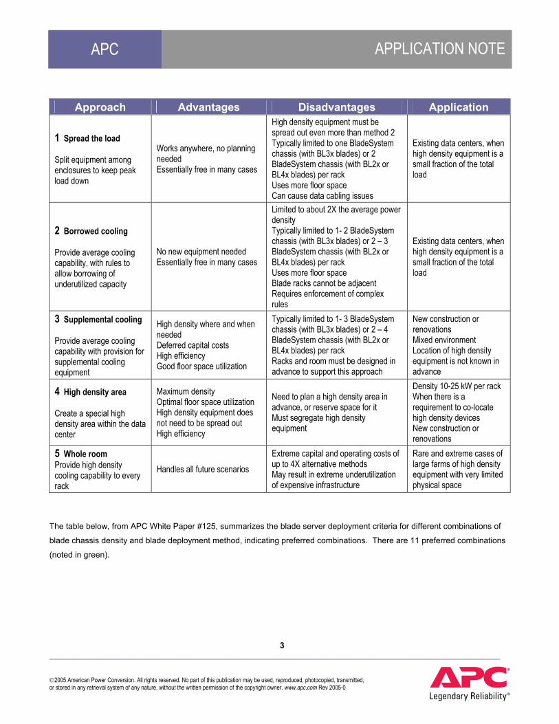
Approach Advantages Disadvantages Application
1 Spread the load Split equipment among enclosures to keep peak load down
Works anywhere, no planning needed Essentially free in many cases
High density equipment must be spread out even more than method 2 Typically limited to one BladeSystem chassis (with BL3x blades) or 2 BladeSystem chassis (with BL2x or BL4x blades) per rack Uses more floor space Can cause data cabling issues
Existing data centers, when high density equipment is a small fraction of the total load
2 Borrowed cooling Provide average cooling capability, with rules to allow borrowing of underutilized capacity
No new equipment needed Essentially free in many cases
Limited to about 2X the average power density Typically limited to 1- 2 BladeSystem chassis (with BL3x blades) or 2 – 3 BladeSystem chassis (with BL2x or BL4x blades) per rack Uses more floor space Blade racks cannot be adjacent Requires enforcement of complex rules
Existing data centers, when high density equipment is a small fraction of the total load
3 Supplemental cooling Provide average cooling capability with provision for supplemental cooling equipment
High density where and when needed Deferred capital costs High efficiency Good floor space utilization
Typically limited to 1- 3 BladeSystem chassis (with BL3x blades) or 2 – 4 BladeSystem chassis (with BL2x or BL4x blades) per rack Racks and room must be designed in advance to support this approach
New construction or renovations Mixed environment Location of high density equipment is not known in advance
4 High density area Create a special high density area within the data center
Maximum density Optimal floor space utilization High density equipment does not need to be spread out High efficiency
Need to plan a high density area in advance, or reserve space for it Must segregate high density equipment
Density 10-25 kW per rack When there is a requirement to co-locate high density devices New construction or renovations
5 Whole room Provide high density cooling capability to every rack
Handles all future scenarios Extreme capital and operating costs of up to 4X alternative methods May result in extreme underutilization of expensive infrastructure
Rare and extreme cases of large farms of high density equipment with very limited physical space
The table below, from APC White Paper #125, summarizes the blade server deployment criteria for different combinations of
blade chassis density and blade deployment method, indicating preferred combinations. There are 11 preferred combinations
(noted in green).

4 ___________________________________________________________________________________________________ 2005 American Power Conversion. All rights reserved. No part of this publication may be used, reproduced, photocopied, transmitted, or stored in any retrieval system of any nature, without the written permission of the copyright owner. www.apc.com Rev 2005-0
APC APPLICATION NOTE
# Chassis per rack
Spread the
Load
Borrowed Cooling
Supplemental Cooling
High Density Area Whole room
1 Most data centers can accommodate
All data centers can accommodate
All data centers can accommodate. Adjacent blade racks allowed
Not cost effective compared with alternatives
Not cost effective compared to alternatives
2
Only if data center has unusually high cooling distribution capacity
Most data centers can accommodate, use of adjacent racks may be restricted
All data centers can accommodate. Adjacent blade racks allowed
Not cost effective compared with alternatives. A higher density target should be set for new zones or rows.
Not cost effective compared with alternatives. A higher density target should be set for a whole room.
3 Impractical: power density exceeds typical data center capacity
Most data centers can accommodate, but adjacent racks are not practical in most cases
Requires hot air return plenum or ductwork. Adjacent blade racks allowed.
The maximum limit for well designed raised floor cooling systems
Not cost effective compared with alternatives. A higher density target should be set for a whole room.
4 Impractical: power density exceeds typical data center capacity
Data center must have unusually high cooling distribution capacity, rules are strict
Depends on the specific combination of blade server and supplemental cooling solution
Hot air scavenging systems are needed
Hot air scavenging systems are needed. Total room rebuild required.
5 Impractical: power density exceeds typical data center capacity
Impractical: power density exceeds typical data center capacity
Impractical: power density exceeds capability of known supplemental cooling devices
Hot air scavenging systems are needed
Hot air scavenging systems are needed. Total room rebuild required.
6 Impractical: power density exceeds typical data center capacity
Impractical: power density exceeds typical data center capacity
Impractical: power density exceeds capability of known supplemental cooling devices
Only if there is a severe area limitation. The cost may be extreme to achieve this density over a sustained area. May require rules.
The cost may be extreme to achieve this density. Total room rebuild required. Hot air scavenging systems are needed.
Minimal cost Minimal cost $1k-2k per rack $10k-20k per rack $20k-$60k per rack
Increasing cost
Easy Procedures required Non-invasive installation
Major installation, piping and wiring
Total room shutdown & rebuild
Increasing deployment complexity

5 ___________________________________________________________________________________________________ 2005 American Power Conversion. All rights reserved. No part of this publication may be used, reproduced, photocopied, transmitted, or stored in any retrieval system of any nature, without the written permission of the copyright owner. www.apc.com Rev 2005-0
APC APPLICATION NOTE
Rack Specification The rack enclosure must physically support the BladeSystem chassis and have provision for power and data cabling to support
the servers while allowing proper air flow into and out of the rack. The following attributes summarize the rack enclosure
specifications for the HP BladeSystem p-Class servers.
HP Blade Server Attribute Value for HP BL2X /
4X
Value for HP BL3X
Notes
Height of one chassis 6U 6U This equates to a maximum of 5 chassis and 2 power supply enclosures per 42U rack for the HP BL2X / 4X and 5 chassis and 4 power supply enclosure per 42U rack for the HP BL3X
Number of servers per chassis 8 for BL2X 2 for BL4X 16
This equates to a maximum of 40 servers per 42U rack for the HP BL2X, 10 servers per 42U rack for the HP BL4X, and 80 servers per 42U rack for the HP BL3X
Weight of fully configured rack 1950 lbs (885 kg)
2064 lbs (936 kg)
This includes the rack and fully configured equipment. This equates to approximately 279 lbs / ft2 (3003 kg / m2), which may exceed the room’s floor loading limits (not including weight of rack). For instance, there are high-rise buildings that have weight restrictions of 125 lbs / ft2 (1345 kg / m2)
Maximum quantity of power cords per 42U rack 4 8 Each power cord connects directly to an L15-
30 whip Mounting requirements Rail Kit required Rail Kit required HP chassis hardware is included
Required door perforations 65% Open 65% Open HP requires perforations on both front and rear doors of rack enclosure
Front to rear rail distance 29 – 30 inches ( 74 – 76 cm)
29 – 30 inches ( 74 – 76 cm)
Racks must have a minimum rail-to-rail distance of 29 inches (74 cm) to accommodate the HP blades
Front rail clearance 2.5 inches ( 6.4 cm)
2.5 inches ( 6.4 cm)
Rack enclosure must meet this minimum clearance in order for front door to close
Rear rail clearance 3.5 inches ( 8.9 cm)
3.5 inches ( 8.9 cm)
Rack enclosure must meet this minimum clearance in order for rear door to close
Based on these attributes, the APC NetShelter VX is the suggested rack solution for all deployment methods. The NetShelter
VX (part # AR2100BLK for single rack and part # AR2101BLK for rack without sides – for baying multiple racks), has vendor-
neutral mounting, can support 2000 lbs (907kg) of load, has pre-engineered accommodations for up to four vertically mounted
(zero U) PDUs and has over 800 sq inches (0.516 sq m) of open surface area (66%) on the front and rear doors to

6 ___________________________________________________________________________________________________ 2005 American Power Conversion. All rights reserved. No part of this publication may be used, reproduced, photocopied, transmitted, or stored in any retrieval system of any nature, without the written permission of the copyright owner. www.apc.com Rev 2005-0
APC APPLICATION NOTE
accommodate proper cooling. The NetShelter VX also has options for overhead data and power cable distribution, rack cable
management, and air distribution, which are all described later in the Cooling and Power sections.
Note – If the weight of any configured rack exceeds the floor-loading limitations of the room, the number of chassis must be
reduced accordingly.
Cooling Specification Cooling is the most critical issue with blade server deployments. Sufficient cool air must be delivered to the front of the HP
blade chassis while simultaneously removing the same amount of hot air from the back. Specifically, the cooling solution must
not only accommodate the required inlet air temperature of the blades, but also deliver the needed air flow. The follow
attributes help identify the cooling specifications for the HP BladeSystem p-class servers.
HP Blade Server Attribute Value for HP BL2X / 4X
Value for HP BL3X
Notes
Operating temperature 50 – 95F (10 - 35C) 50 – 95F (10 - 35C)
Operating humidity 20-80% Relative Humidity (RH)
20-80% Relative Humidity (RH)
Typical measured airflow requirement of one chassis
135 CFM (63.7 L / s)
240* CFM ( 113 L / s)
Typical measured airflow requirement of one power supply enclosure
80 CFM (37.8 L / s)
80 CFM (37.8 L / s)
This equates to a typical airflow of 835 CFM (394 L / s) for a fully configured 42U rack with the HP BL2X and 1840* CFM (868 L / s) for a fully configured 42U rack with the HP BL3X
Worst case measured airflow requirement of one chassis
235 CFM (110.9 L / s)
363* CFM (171.3 L / s)
Worst case measured airflow requirement of one power supply enclosure
80 CFM (37.8 L / s)
80 CFM (37.8 L / s)
This equates to a worst case airflow of 1335 CFM (630 L / s) for a fully configured 42U rack with the HP BL2X and 2740* CFM (1293 L / s) for a fully configured 42U rack with the HP BL3X
* These are estimated by APC
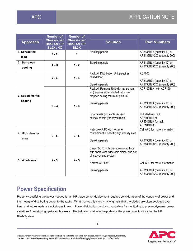
The table below presents the suggested cooling solution(s), based on these attributes, and the five deployment approaches for
a varying number of chassis per rack. In addition to these solutions, it is suggested to deploy the blades using the following
best practices:
• Install racks in a hot-aisle / cold-aisle arrangement with the air return plenums for the CRAC units aligned with
hot aisles. This minimizes the amount of hot air that is allowed to mix the cold supply air to the servers. The
hot aisle should be at least 3 ft (0.9144 m) wide and the cold aisle should be at least 4 ft (1.219 m) wide.
• Fill all unused U positions within all racks with solid blanking panels to keep air from re-circulating between the
aisles.

7 ___________________________________________________________________________________________________ 2005 American Power Conversion. All rights reserved. No part of this publication may be used, reproduced, photocopied, transmitted, or stored in any retrieval system of any nature, without the written permission of the copyright owner. www.apc.com Rev 2005-0
APC APPLICATION NOTE
• Fill all unused slots and modules within the chassis with filler blades to ensure proper airflow within the chassis.
• Install blade chassis starting at the bottom of the rack to improve stability and provide the coolest inlet air
possible.
• Install blades into slots on alternate ends of the chassis, working towards the middle. This spreads the load
across power domains, lowers the operating temperature of downstream components, and ensures continued
operation of half the blades if a power domain fails.
• If possible, use internal switch modules rather than pass-thru modules to minimize cable bundles and improve
airflow.
APC has two air distribution products that can be used to increase rack cooling capacity. The APC Rack Air Distribution Unit
(ADU) is a 2U rack-mount air moving device that supplies air to up to 3 BladeSystem p-Class chassis (BL3X blades) and up to
4 chassis (BL2X/4X blades) in a raised-floor environment. It draws air through a flexible plenum from under the floor and
delivers it to the intake of the servers at the front of the rack. See Figure 1 on page 10.
The APC Rack Air Removal Unit (ARU) is an air moving device that replaces the rear door of a NetShelter VX rack and
removes hot air from up to 3 BladeSystem p-class chassis (BL3X blades) and up to 4 chassis (BL2X / 4X blades). It collects
the hot air from the back of the rack and delivers it into the return air plenum. See Figure 1 on page 10.
APC’s NetworkAIR IR is a precision air conditioner that draws hot air in from the rear of the rack (hot aisle), cools it and expels
the cool air into the cold aisle. Increased rack density is achieved because the architecture is not limited by the amount of
airflow that can be supplied by the floor tiles. For high density loads, this In-Row system is outfitted with a hot-aisle
containment system, which includes a roof and row-end door kit that will fully contain the hot aisles of the data center, thereby
eliminating all air mixing. See Figure 2 on page 10.
8 ___________________________________________________________________________________________________ 2005 American Power Conversion. All rights reserved. No part of this publication may be used, reproduced, photocopied, transmitted, or stored in any retrieval system of any nature, without the written permission of the copyright owner. www.apc.com Rev 2005-0
APC APPLICATION NOTE
Approach Number of
Chassis per Rack for HP BL2X / 4X
Number of Chassis per Rack for HP
BL3X Solution Part Numbers
1. Spread the
load 1 - 2 1
Blanking panels AR8136BLK (quantity 10) or AR8136BLK200 (quantity 200)
2. Borrowed
cooling 1 – 3 1 - 2
Blanking panels AR8136BLK (quantity 10) or AR8136BLK200 (quantity 200)
2 - 4 1 - 3 Rack Air Distribution Unit (requires raised floor) Blanking panels
ACF002 AR8136BLK (quantity 10) or AR8136BLK200 (quantity 200)
3. Supplemental
cooling
2 – 4 1 - 3
Rack Air Removal Unit with top plenum kit (requires either ducted returns or dropped ceiling return air plenum) Blanking panels Side panels (for single rack) or privacy panels (for bayed racks)
ACF103BLK with ACF120 AR8136BLK (quantity 10) or AR8136BLK200 (quantity 200) Included with rack AR2100BLK or AR8349BLK for rack AR2101BLK
4. High density
area 3 - 5 3 - 5
NetworkAIR IR with hot-aisle containment in specific high density area Blanking panels
Call APC for more information AR8136BLK (quantity 10) or AR8136BLK200 (quantity 200)
5. Whole room 4 - 5 4 - 5
Deep (2-3 ft) high pressure raised floor with short rows, wide cold aisles, and hot air scavenging system NetworkAIR CW Blanking panels
Call APC for more information AR8136BLK (quantity 10) or AR8136BLK200 (quantity 200)
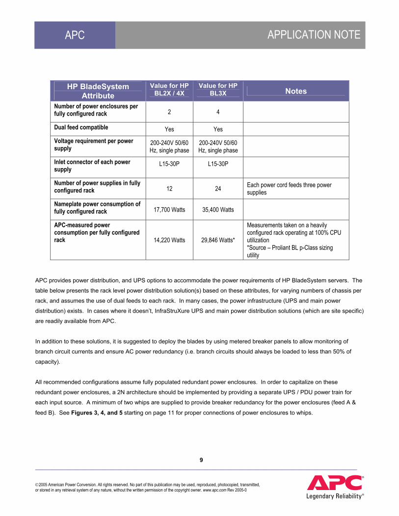
Power Specification Properly specifying the power needed for an HP blade server deployment requires consideration of the capacity of power and
the means of distributing power to the racks. What makes this more challenging is that the blades are often deployed over
time, and future loads are not always known. Power distribution products must allow for monitoring to prevent dynamic power
variations from tripping upstream breakers. The following attributes help identify the power specifications for the HP
BladeSystem.
9 ___________________________________________________________________________________________________ 2005 American Power Conversion. All rights reserved. No part of this publication may be used, reproduced, photocopied, transmitted, or stored in any retrieval system of any nature, without the written permission of the copyright owner. www.apc.com Rev 2005-0
APC APPLICATION NOTE
HP BladeSystem Attribute
Value for HP BL2X / 4X
Value for HP BL3X Notes
Number of power enclosures per fully configured rack 2 4
Dual feed compatible Yes Yes
Voltage requirement per power supply
200-240V 50/60 Hz, single phase
200-240V 50/60 Hz, single phase
Inlet connector of each power supply
L15-30P
L15-30P
Number of power supplies in fully configured rack 12 24 Each power cord feeds three power
supplies
Nameplate power consumption of fully configured rack 17,700 Watts 35,400 Watts
APC-measured power consumption per fully configured rack 14,220 Watts 29,846 Watts*
Measurements taken on a heavily configured rack operating at 100% CPU utilization *Source – Proliant BL p-Class sizing utility
APC provides power distribution, and UPS options to accommodate the power requirements of HP BladeSystem servers. The
table below presents the rack level power distribution solution(s) based on these attributes, for varying numbers of chassis per
rack, and assumes the use of dual feeds to each rack. In many cases, the power infrastructure (UPS and main power
distribution) exists. In cases where it doesn’t, InfraStruXure UPS and main power distribution solutions (which are site specific)
are readily available from APC.
In addition to these solutions, it is suggested to deploy the blades by using metered breaker panels to allow monitoring of
branch circuit currents and ensure AC power redundancy (i.e. branch circuits should always be loaded to less than 50% of
capacity).
All recommended configurations assume fully populated redundant power enclosures. In order to capitalize on these
redundant power enclosures, a 2N architecture should be implemented by providing a separate UPS / PDU power train for
each input source. A minimum of two whips are supplied to provide breaker redundancy for the power enclosures (feed A &
feed B). See Figures 3, 4, and 5 starting on page 11 for proper connections of power enclosures to whips.

10 ___________________________________________________________________________________________________ 2005 American Power Conversion. All rights reserved. No part of this publication may be used, reproduced, photocopied, transmitted, or stored in any retrieval system of any nature, without the written permission of the copyright owner. www.apc.com Rev 2005-0
APC APPLICATION NOTE
Number of Chassis per Rack
Solution Part Numbers Notes
1 (2) L6-30 whips Branch Current Monitoring Kit
(2) PDWXXL6-30C* (1) PDBC100
This assumes 1 power enclosure, power bus box
2 (2) L15-30 whips Branch Current Monitoring Kit
(2) PDWXXL15-30C* (1) PDBC100
This assumes 2 power enclosures, scalable or mini bus bars
(4) L15-30 whips Branch Current Monitoring Kit
(4) PDWXXL15-30C* (1) PDBC100
BL2X blades – This assumes 2 power enclosures, scalable bus bars
3 - 5 (8) L15-30 whips Branch Current Monitoring Kit
(8) PDWXXL15-30C* (2) PDBC100
BL3X blades - This assumes 4 power enclosures, 2 sets of mini bus bars
* Replace XX with the length in feet – whips are available in 2 ft increments, between 5 ft and 61 ft.
Management Specification Having visibility to many data points is required for the reliable operation of Network-Critical Physical Infrastructure (NCPI) and
specifically the availability needs of HP BladeSystems. Critical data points that should be monitored include current monitoring
per branch circuit, inlet temperatures to racks, humidity levels, AC voltages, and UPS and battery status. APC’s InfraStruXure
power, rack and cooling components have built-in remote management capabilities ensuring that access to individual devices
is both easy and economical. Each browser-accessible device is quickly accessed from anywhere on the network without the
need to install client software. Identifying problematic trends before they escalate is made easy with an exportable data log.
An event log enables to the operator to pinpoint the timing and sequence of events leading up to an incident. SNMP trap
forwarding allows individual devices to be integrated with an enterprise management system.
The suggested management solution(s) for all blade deployment approaches is the same – APC InfraStruXure Manager (part
# AP9420 for 25 nodes, AP9421 for 100 nodes, AP9422 for 500 nodes, and AP9423 for 1000 nodes). APC’s InfraStruXure
Manager enables centralized management for up to a maximum of one thousand APC devices located throughout a network.
A private IP network provides the option of monitoring of up to 253 APC devices from a single IP address. InfraStruXure
Manager enables the quick assessment of your present situation and notifies the appropriate personnel should situations that
threaten availability occur. Analysis features help to plan for changes in availability, power, runtime or cooling requirements.
SNMP trap forwarding is used to send data to enterprise management systems, and the Modbus RTU protocol enables alarms
and data points to be sent to your building management systems.
Close management of a high density NCPI increases the overall system availability by allowing the user to identify any power
and thermal anomalies, and correct them before they cause a failure. APC recommends the use of an InfraStruXure Manger,

11 ___________________________________________________________________________________________________ 2005 American Power Conversion. All rights reserved. No part of this publication may be used, reproduced, photocopied, transmitted, or stored in any retrieval system of any nature, without the written permission of the copyright owner. www.apc.com Rev 2005-0
APC APPLICATION NOTE
metered RM PDUs, and an environmental monitoring unit with two temperature probes (top and bottom) on the front (air inlet)
of each rack.
Conclusion This Application Note describes how to successfully and predictably deploy HP BladeSystem p-Class servers using the APC
InfraStruXure system. For new data centers, designing high density zones or rows is typically the preferred approach. This is
because designing an entire data center for high density is generally costly, inefficient, and actually wastes floor space.
For existing data centers, the use of supplemental cooling or borrowing rules is preferred for deployments in which
BladeSystems are a small fraction of the total installation. This is because these are the least intrusive installation methods
with the least risk of interfering with an operating data center. When the number of BladeSystem racks being deployed in an
existing data center begins to exceed 5 racks or 10% of the total racks, high density zones or rows are the preferred approach.
This is because spreading begins to become unmanageable and less effective with this quantity or fraction of blade racks.
When the number of BladeSystem racks begins to exceed 10 or 25% of racks, building a new room is recommended.
For powering HP BladeSystems, APC offers L6-30 and L15-30 whips. The L6-30 whips should only be used for single chassis
deployments, and the L15-30 whips should be used in all other cases.
For cooling the HP BladeSystem, the key is to manage airflow effectively. For lower density deployments, APC offers the Rack
Air Distribution Unit or Rack Air Removal Unit. For deployments at maximum density, APC suggests the APC NetworkAIR In-
Row precision air conditioner with Hot-Aisle Containment.
APC uses computer aided tools to design zones, rows, or complete data centers for blade servers. Consult an APC sales
representative for more information on these tools. APC also offers professional assessment and planning services that can
assist with blade server deployments.

12 ___________________________________________________________________________________________________ 2005 American Power Conversion. All rights reserved. No part of this publication may be used, reproduced, photocopied, transmitted, or stored in any retrieval system of any nature, without the written permission of the copyright owner. www.apc.com Rev 2005-0
APC APPLICATION NOTE
Diagrams
Figure 1 – APC Air Distribution Unit and Air Removal Unit
Figure 2 –NetworkAIR In-Row cooling with hot aisle containment system
ADU ARU

13 ___________________________________________________________________________________________________ 2005 American Power Conversion. All rights reserved. No part of this publication may be used, reproduced, photocopied, transmitted, or stored in any retrieval system of any nature, without the written permission of the copyright owner. www.apc.com Rev 2005-0
APC APPLICATION NOTE
Figure 3 – Recommended power whips for 1 chassis with 1 power supply enclosure and power buss box
Feed ARear View
(2) PDWXXL6-30C L6-30 Whip
Chassis 1
Power SupplyEnclosure 1
WHIP1
Feed BWHIP2

14 ___________________________________________________________________________________________________ 2005 American Power Conversion. All rights reserved. No part of this publication may be used, reproduced, photocopied, transmitted, or stored in any retrieval system of any nature, without the written permission of the copyright owner. www.apc.com Rev 2005-0
APC APPLICATION NOTE
Figure 4 – Recommended power whips for 2 - 5 chassis with 2 power supply enclosures and scalable bus bars
Feed ARear View
(4) PDWXXL15-30C L15-30 Whip
Chassis 2
Chassis 1
Chassis 3
Chassis 5
Chassis 4
Power SupplyEnclosure 2
Power SupplyEnclosure 1
WHIP1WHIP3
Feed BWHIP2 WHIP4
Note: Solution is limited to only 3 chassis if BL3X blades are used

15 ___________________________________________________________________________________________________ 2005 American Power Conversion. All rights reserved. No part of this publication may be used, reproduced, photocopied, transmitted, or stored in any retrieval system of any nature, without the written permission of the copyright owner. www.apc.com Rev 2005-0
APC APPLICATION NOTE
Figure 5 – Recommended power whips for 4 - 5 chassis with 4 power supply enclosures and mini bus bars
Feed ARear View
WHIP7
(8) PDWXXL15-30C L15-30 Whip
Chassis 2
Chassis 1
Chassis 3
Chassis 5
Chassis 4
Power SupplyEnclosure 3
Power SupplyEnclosure 4
Power SupplyEnclosure 2
Power SupplyEnclosure 1
WHIP1WHIP3WHIP5
Feed BWHIP2 WHIP8WHIP6WHIP4