configuration and customization guide -...
TRANSCRIPT

Configuration and Customization GuideOMEGAMON II ® for CICS
Version 520
GC32-9242-00
October 2001
Candle Corporation201 North Douglas Street
El Segundo, California 90245-9796
2 OMEGAMON II for CICS Configuretion and Customization Guide Version 520
Registered trademarks and service marks of Candle Corporation: AF/OPERATOR, AF/PERFORMER, AF/REMOTE, Availability Command Center, Candle, Candle Command Center, Candle Direct logo, Candle Electronic Customer Support, Candle logo, Candle Management Server, Candle Management Workstation, Candle Technologies, CL/CONFERENCE, CL/SUPERSESSION, CommandWatch, CT, CT/Data Server, CT/DS, DELTAMON, eBA*ServiceMonitor, eBA*ServiceNetwork, ETEWatch, IntelliWatch, IntelliWatch Pinnacle, MQSecure, MQView, OMEGACENTER, OMEGAMON, OMEGAMON/e, OMEGAMON II, OMEGAMON Monitoring Agent, OMEGAVIEW, OMEGAVIEW II, PQEdit, Solutions for Networked Applications, Solutions for Networked Businesses, and Transplex.Trademarks and service marks of Candle Corporation: Alert Adapter, Alert Adapter Plus, Alert Emitter, AMS, Amsys, AutoBridge, AUTOMATED FACILITIES, Availability Management Systems, Candle Alert, Candle Business Partner Logo, Candle Command Center/SentinelManager, Candle CommandPro, CandleLight, CandleNet, CandleNet 2000, CandleNet Command Center, CandleNet eBP, CandleNet eBP Access, CandleNet eBP Administrator, CandleNet eBP Broker Access, CandleNet eBP Configuration, CandleNet eBP Connector, CandleNet eBP File Transfer, CandleNet eBP Host Connect, CandleNet eBP Object Access, CandleNet eBP Object Browser, CandleNet eBP Secure Access, CandleNet eBP Service Directory, CandleNet eBP Universal Connector, CandleNet eBP Workflow Access, CandleNet eBusiness Assurance, CandleNet eBusiness Exchange, CandleNet eBusiness Platform, CandleNet eBusiness Platform Administrator, CandleNet eBusiness Platform Connector, CandleNet eBusiness Platform Connectors, CandleNet eBusiness Platform Powered by Roma Technology, CandleNet eBusiness Platform Service Directory, CandleNet Portal, CCC, CCP, CEBA, CECS, CICAT, CL/ENGINE, CL/GATEWAY, CL/TECHNOLOGY, CMS, CMW, Command & Control, Connect-Notes, Connect-Two, CSA ANALYZER, CT/ALS, CT/Application Logic Services, CT/DCS, CT/Distributed Computing Services, CT/Engine, CT/Implementation Services, CT/IX, CT/Workbench, CT/Workstation Server, CT/WS, DB Logo, DB/DASD, �DB/EXPLAIN, �DB/MIGRATOR, �DB/QUICKCHANGE, �DB/QUICKCOMPARE, �DB/SMU, �DB/Tools, �DB/WORKBENCH, Design Network, DEXAN, e2e, eBA, eBAA, eBAAuditor, eBAN, eBANetwork, eBAAPractice, eBP, eBusiness Assurance, eBusiness Assurance Network, eBusiness at the speed of light, eBusiness at the speed of light logo, eBusiness Exchange, eBusiness Institute, eBX, End-to-End, ENTERPRISE, Enterprise Candle Command Center, Enterprise Candle Management Workstation, Enterprise Reporter Plus, EPILOG, ER+, ERPNet, ESRA, ETEWatch Customizer, HostBridge, InterFlow, Candle InterFlow, Lava Console, MessageMate, Messaging Mastered, Millennium Management Blueprint, MMNA, MQADMIN, MQEdit, MQEXPERT, MQMON, NBX, NetGlue, NetGlue Extra, NetMirror, NetScheduler, OMA, OMC Gateway, OMC Status Manager, OMEGACENTER Bridge, OMEGACENTER Gateway, OMEGACENTER Status Manager, OMEGAMON Management Center, OSM, PC COMPANION, Performance Pac, PowerQ, PQConfiguration, PQScope, Response Time Network, Roma, Roma Application Manager, Roma Broker, Roma BSP, Roma Connector, Roma Developer, Roma FS/A, Roma FS/Access, RomaNet, Roma Network, Roma Object Access, Roma Secure, Roma WF/Access, Roma Workflow Access, RTA, RTN, SentinelManager, Somerset, Somerset Systems, Status Monitor, The Millennium Alliance, The Millennium Alliance logo, The Millennium Management Network Alliance, TMA2000, Tracer, Unified Directory Services, Volcano and ZCopy.Trademarks and registered trademarks of other companies: AIX, DB2, MQSeries and WebSphere are registered trademarks of International Business Machines Corporation. SAP is a registered trademark and R/3 is a trademark of SAP AG. UNIX is a registered trademark in the U.S. and other countries, licensed exclusively through X/Open Company Ltd. HP-UX is a trademark of Hewlett-Packard Company. SunOS is a trademark of Sun Microsystems, Inc. All other company and product names used herein are trademarks or registered trademarks of their respective companies.
Copyright © October 2001, Candle Corporation, a California corporation. All rights reserved. International rights secured.
Threaded Environment for AS/400, Patent No. 5,504,898; Data Server with Data Probes Employing Predicate Tests in Rule Statements (Event Driven Sampling), Patent No. 5,615,359; MVS/ESA Message Transport System Using the XCF Coupling Facility, Patent No. 5,754,856; Intelligent Remote Agent for Computer Performance Monitoring, Patent No. 5,781,703; Data Server with Event Driven Sampling, Patent No. 5,809,238; Threaded Environment for Computer Systems Without Native Threading Support, Patent No. 5,835,763; Object Procedure Messaging Facility, Patent No. 5,848,234; End-to-End Response Time Measurement for Computer Programs, Patent No. 5,991,705; Communications on a Network, Patent Pending; Improved Message Queuing Based Network Computing Architecture, Patent Pending; User Interface for System Management Applications, Patent Pending.
NOTICE: This documentation is provided with RESTRICTED RIGHTS. Use, duplication, or disclosure by the Government is subject to restrictions set forth in the applicable license agreement and/or the applicable government rights clause.This documentation contains confidential, proprietary information of Candle Corporation that is licensed for your internal use only. Any unauthorized use, duplication, or disclosure is unlawful.

Table of Contents 3
Table of Contents . . . . . . . . . . . . . . . . . . . . . . . . . . . . . . . . . . . . . . . . . . . . . . . . . . . . . . . . . . . . . .3
List Of Figures . . . . . . . . . . . . . . . . . . . . . . . . . . . . . . . . . . . . . . . . . . . . . . . . . . . . . . . . . . . . . .7
List Of Tables . . . . . . . . . . . . . . . . . . . . . . . . . . . . . . . . . . . . . . . . . . . . . . . . . . . . . . . . . . . . . .9
Preface . . . . . . . . . . . . . . . . . . . . . . . . . . . . . . . . . . . . . . . . . . . . . . . . . . . . . . . . . . . . .11Adobe Portable Document Format . . . . . . . . . . . . . . . . . . . . . . . . . . . . . . . . . . . . . . . .14
Chapter 1. Background about Components and Modes of Operation. . . . . . . . . . . . . . . . .15Product Components . . . . . . . . . . . . . . . . . . . . . . . . . . . . . . . . . . . . . . . . . . . . . . . . . .16Details about the User Interfaces . . . . . . . . . . . . . . . . . . . . . . . . . . . . . . . . . . . . . . . . . .18Details about the Candle Subsystem . . . . . . . . . . . . . . . . . . . . . . . . . . . . . . . . . . . . . . .20Modes of Operation . . . . . . . . . . . . . . . . . . . . . . . . . . . . . . . . . . . . . . . . . . . . . . . . . . .22
Chapter 2. Installing, Configuring, and Customizing OMEGAMON II for CICS . . . . . . . . .25Information Covered in this Chapter . . . . . . . . . . . . . . . . . . . . . . . . . . . . . . . . . . . . . . .26Configuration Planning and Considerations . . . . . . . . . . . . . . . . . . . . . . . . . . . . . . . . .27Overview of the Process . . . . . . . . . . . . . . . . . . . . . . . . . . . . . . . . . . . . . . . . . . . . . . . .33Getting Help with CICAT. . . . . . . . . . . . . . . . . . . . . . . . . . . . . . . . . . . . . . . . . . . . . . . .34CICAT Background and Requirements . . . . . . . . . . . . . . . . . . . . . . . . . . . . . . . . . . . . .35CICAT Installation Procedure . . . . . . . . . . . . . . . . . . . . . . . . . . . . . . . . . . . . . . . . . . . .36CICAT Configuration Procedures . . . . . . . . . . . . . . . . . . . . . . . . . . . . . . . . . . . . . . . . .37Manual Configuration Procedures . . . . . . . . . . . . . . . . . . . . . . . . . . . . . . . . . . . . . . . . .40Manual Customization Procedures . . . . . . . . . . . . . . . . . . . . . . . . . . . . . . . . . . . . . . . .41
Chapter 3. Completing the Configuration. . . . . . . . . . . . . . . . . . . . . . . . . . . . . . . . . . . . . .43Copying to System Libraries . . . . . . . . . . . . . . . . . . . . . . . . . . . . . . . . . . . . . . . . . . . . .44Adding ETE to the PROCLIB . . . . . . . . . . . . . . . . . . . . . . . . . . . . . . . . . . . . . . . . . . . .45Giving Started Tasks Access to High-level Qualifier . . . . . . . . . . . . . . . . . . . . . . . . . . . .46Verifying Installation and Configuration. . . . . . . . . . . . . . . . . . . . . . . . . . . . . . . . . . . . .47
Chapter 4. Modes of Operation . . . . . . . . . . . . . . . . . . . . . . . . . . . . . . . . . . . . . . . . . . . . .53Customizing the Modes of Operation. . . . . . . . . . . . . . . . . . . . . . . . . . . . . . . . . . . . . . .54Installing in TSO Mode . . . . . . . . . . . . . . . . . . . . . . . . . . . . . . . . . . . . . . . . . . . . . . . . .57Installing in ISPF Mode . . . . . . . . . . . . . . . . . . . . . . . . . . . . . . . . . . . . . . . . . . . . . . . . .60Installing in Dedicated Mode . . . . . . . . . . . . . . . . . . . . . . . . . . . . . . . . . . . . . . . . . . . . .62
Chapter 5. Modifying the CICS Tables and JCL . . . . . . . . . . . . . . . . . . . . . . . . . . . . . . . . .65System Initialization Table (SIT). . . . . . . . . . . . . . . . . . . . . . . . . . . . . . . . . . . . . . . . . . .66Program Load Table (PLT) . . . . . . . . . . . . . . . . . . . . . . . . . . . . . . . . . . . . . . . . . . . . . .67
Table of Contents
4 OMEGAMON II for CICS Configuration and Customization Guide Version 520
Monitoring Control Table (MCT) . . . . . . . . . . . . . . . . . . . . . . . . . . . . . . . . . . . . . . . . . .68Defining the OMEGAMON II Program and Transaction. . . . . . . . . . . . . . . . . . . . . . . . .73Defining the Security for the OMEGAMON II Program . . . . . . . . . . . . . . . . . . . . . . . . .75CICS JCL Changes . . . . . . . . . . . . . . . . . . . . . . . . . . . . . . . . . . . . . . . . . . . . . . . . . . . .77
Chapter 6. Specifying the Monitoring Options for the Product . . . . . . . . . . . . . . . . . . . . . .79Background about the Monitoring Options . . . . . . . . . . . . . . . . . . . . . . . . . . . . . . . . . .80Displaying and Printing Information about the Monitoring Options . . . . . . . . . . . . . . . .81Determining What to Do Next . . . . . . . . . . . . . . . . . . . . . . . . . . . . . . . . . . . . . . . . . . . .82Migrating the Monitoring Options for the Product . . . . . . . . . . . . . . . . . . . . . . . . . . . . .83Specifying the Values for the Monitoring Options in the Product . . . . . . . . . . . . . . . . . .88Refreshing the Monitoring Options . . . . . . . . . . . . . . . . . . . . . . . . . . . . . . . . . . . . . . . .96Additional Considerations . . . . . . . . . . . . . . . . . . . . . . . . . . . . . . . . . . . . . . . . . . . . . . .97
Chapter 7. Starting and Logging Onto the Product. . . . . . . . . . . . . . . . . . . . . . . . . . . . . .103Starting the Collector. . . . . . . . . . . . . . . . . . . . . . . . . . . . . . . . . . . . . . . . . . . . . . . . . .104Starting the CUA Interface (Optional) . . . . . . . . . . . . . . . . . . . . . . . . . . . . . . . . . . . . .105Initializing the CICS Connection . . . . . . . . . . . . . . . . . . . . . . . . . . . . . . . . . . . . . . . . .106The OMEGAMON II Service Task . . . . . . . . . . . . . . . . . . . . . . . . . . . . . . . . . . . . . . . .107Stopping the Collector. . . . . . . . . . . . . . . . . . . . . . . . . . . . . . . . . . . . . . . . . . . . . . . . .108Stopping the CUA Interface. . . . . . . . . . . . . . . . . . . . . . . . . . . . . . . . . . . . . . . . . . . . .109Logging Onto the OMEGAMON II Menu System in VTAM Mode . . . . . . . . . . . . . . . .110Logging Onto the OMEGAMON II Menu System in TSO Mode. . . . . . . . . . . . . . . . . .111Logging Onto the OMEGAMON II Menu System in ISPF Mode . . . . . . . . . . . . . . . . .112Logging Onto the OMEGAMON II Menu System in Dedicated Mode . . . . . . . . . . . . .113Simplified Signon . . . . . . . . . . . . . . . . . . . . . . . . . . . . . . . . . . . . . . . . . . . . . . . . . . . .114Logging Off the Menu System in VTAM, TSO, or ISPF Mode . . . . . . . . . . . . . . . . . . .118Logging Off the OMEGAMON II Menu System in Dedicated Mode . . . . . . . . . . . . . . .119Logging Off the CUA Interface . . . . . . . . . . . . . . . . . . . . . . . . . . . . . . . . . . . . . . . . . .120
Chapter 8. Customizing CUA Interface Profiles . . . . . . . . . . . . . . . . . . . . . . . . . . . . . . . .121About CUA Interface Profiles. . . . . . . . . . . . . . . . . . . . . . . . . . . . . . . . . . . . . . . . . . . .122Specifying a Region Profile and Migrating Thresholds . . . . . . . . . . . . . . . . . . . . . . . . .123Switching Profiles . . . . . . . . . . . . . . . . . . . . . . . . . . . . . . . . . . . . . . . . . . . . . . . . . . . .124Dynamic Profile Update Facility. . . . . . . . . . . . . . . . . . . . . . . . . . . . . . . . . . . . . . . . . .125$DEFAULT Region Profile . . . . . . . . . . . . . . . . . . . . . . . . . . . . . . . . . . . . . . . . . . . . . .126
Chapter 9. Customizing CUA Interface Security. . . . . . . . . . . . . . . . . . . . . . . . . . . . . . . .127Choosing Your Security Configuration. . . . . . . . . . . . . . . . . . . . . . . . . . . . . . . . . . . . .128OMEGAMON II Internal Security . . . . . . . . . . . . . . . . . . . . . . . . . . . . . . . . . . . . . . . .129CA-ACF2 External Security . . . . . . . . . . . . . . . . . . . . . . . . . . . . . . . . . . . . . . . . . . . . .131RACF External Security. . . . . . . . . . . . . . . . . . . . . . . . . . . . . . . . . . . . . . . . . . . . . . . .132CA-TOP SECRET External Security . . . . . . . . . . . . . . . . . . . . . . . . . . . . . . . . . . . . . .133Bypassing CUA Interface Security . . . . . . . . . . . . . . . . . . . . . . . . . . . . . . . . . . . . . . . .135

Table of Contents 5
Chapter 10. Function Level Security . . . . . . . . . . . . . . . . . . . . . . . . . . . . . . . . . . . . . . . . .137Background about Function Level Security . . . . . . . . . . . . . . . . . . . . . . . . . . . . . . . . .138Enabling CUA function level security. . . . . . . . . . . . . . . . . . . . . . . . . . . . . . . . . . . . . .139CUA Function Level and Menu System Security . . . . . . . . . . . . . . . . . . . . . . . . . . . . .140Authorizing User Access Example . . . . . . . . . . . . . . . . . . . . . . . . . . . . . . . . . . . . . . . .141External Security Function Level Resources. . . . . . . . . . . . . . . . . . . . . . . . . . . . . . . . .142
Chapter 11. Customizing Menu System Interface Profiles. . . . . . . . . . . . . . . . . . . . . . . . . .145Background about Profiles . . . . . . . . . . . . . . . . . . . . . . . . . . . . . . . . . . . . . . . . . . . . .146Creating an Installation-Defined Profile . . . . . . . . . . . . . . . . . . . . . . . . . . . . . . . . . . . .148Saving the Installation-Defined Profile . . . . . . . . . . . . . . . . . . . . . . . . . . . . . . . . . . . . .150Profile Security . . . . . . . . . . . . . . . . . . . . . . . . . . . . . . . . . . . . . . . . . . . . . . . . . . . . . .151
Chapter 12. Enabling Monitoring for User Defined Events . . . . . . . . . . . . . . . . . . . . . . . . .153Background about Monitoring for User-Defined Events . . . . . . . . . . . . . . . . . . . . . . . .154Overview of the Process for Monitoring for a User-Defined Event . . . . . . . . . . . . . . . .155Specifying the User-Defined Event and Parameters for the Event . . . . . . . . . . . . . . . .156Specifying the Call to the Subroutine in the Application . . . . . . . . . . . . . . . . . . . . . . .157
Chapter 13. Menu System Security Facility . . . . . . . . . . . . . . . . . . . . . . . . . . . . . . . . . . . .161Background about Security for the Menu System . . . . . . . . . . . . . . . . . . . . . . . . . . . .162Using Internal Security for Commands . . . . . . . . . . . . . . . . . . . . . . . . . . . . . . . . . . . .163Locking Feature. . . . . . . . . . . . . . . . . . . . . . . . . . . . . . . . . . . . . . . . . . . . . . . . . . . . . .165Using External Security . . . . . . . . . . . . . . . . . . . . . . . . . . . . . . . . . . . . . . . . . . . . . . . .167Implementing External Security. . . . . . . . . . . . . . . . . . . . . . . . . . . . . . . . . . . . . . . . . .169Modifying the Security Table . . . . . . . . . . . . . . . . . . . . . . . . . . . . . . . . . . . . . . . . . . . .177Security Update Program Listing . . . . . . . . . . . . . . . . . . . . . . . . . . . . . . . . . . . . . . . . .187Creating the SMF Audit . . . . . . . . . . . . . . . . . . . . . . . . . . . . . . . . . . . . . . . . . . . . . . . .192External Security Optional Features. . . . . . . . . . . . . . . . . . . . . . . . . . . . . . . . . . . . . . .193
Chapter 14. SMF Considerations . . . . . . . . . . . . . . . . . . . . . . . . . . . . . . . . . . . . . . . . . . . .195SMF Information Map . . . . . . . . . . . . . . . . . . . . . . . . . . . . . . . . . . . . . . . . . . . . . . . . .196SMF Record Type . . . . . . . . . . . . . . . . . . . . . . . . . . . . . . . . . . . . . . . . . . . . . . . . . . . .198Record Layout . . . . . . . . . . . . . . . . . . . . . . . . . . . . . . . . . . . . . . . . . . . . . . . . . . . . . .199Interval Records . . . . . . . . . . . . . . . . . . . . . . . . . . . . . . . . . . . . . . . . . . . . . . . . . . . . .200System Records. . . . . . . . . . . . . . . . . . . . . . . . . . . . . . . . . . . . . . . . . . . . . . . . . . . . . .201File and Database Records . . . . . . . . . . . . . . . . . . . . . . . . . . . . . . . . . . . . . . . . . . . . .202Transaction Records . . . . . . . . . . . . . . . . . . . . . . . . . . . . . . . . . . . . . . . . . . . . . . . . . .204Dictionary Records . . . . . . . . . . . . . . . . . . . . . . . . . . . . . . . . . . . . . . . . . . . . . . . . . . .206
Chapter 15. Installing Third-Party Support . . . . . . . . . . . . . . . . . . . . . . . . . . . . . . . . . . . . .207Background about the Products Supported . . . . . . . . . . . . . . . . . . . . . . . . . . . . . . . . .208Installing ADABAS Support. . . . . . . . . . . . . . . . . . . . . . . . . . . . . . . . . . . . . . . . . . . . .210Installing CA-DATACOM and CA-IDEAL Support . . . . . . . . . . . . . . . . . . . . . . . . . . . .211Installing GENER/OL Support . . . . . . . . . . . . . . . . . . . . . . . . . . . . . . . . . . . . . . . . . . .212

6 OMEGAMON II for CICS Configuration and Customization Guide Version 520
Installing IDMS Support . . . . . . . . . . . . . . . . . . . . . . . . . . . . . . . . . . . . . . . . . . . . . . .213Installing Millennium Support . . . . . . . . . . . . . . . . . . . . . . . . . . . . . . . . . . . . . . . . . . .215Installing NATURAL Support. . . . . . . . . . . . . . . . . . . . . . . . . . . . . . . . . . . . . . . . . . . .216Installing PCS Support . . . . . . . . . . . . . . . . . . . . . . . . . . . . . . . . . . . . . . . . . . . . . . . .217Installing SUPRA Support . . . . . . . . . . . . . . . . . . . . . . . . . . . . . . . . . . . . . . . . . . . . . .218Installing UFO/Forms Support . . . . . . . . . . . . . . . . . . . . . . . . . . . . . . . . . . . . . . . . . . .219
Chapter 16. Umbrella Transaction Services . . . . . . . . . . . . . . . . . . . . . . . . . . . . . . . . . . . .221Using Subroutines . . . . . . . . . . . . . . . . . . . . . . . . . . . . . . . . . . . . . . . . . . . . . . . . . . . .222Subroutine Call Syntax . . . . . . . . . . . . . . . . . . . . . . . . . . . . . . . . . . . . . . . . . . . . . . . .223
Appendix A. Collector Address Space . . . . . . . . . . . . . . . . . . . . . . . . . . . . . . . . . . . . . . . . .227Collector Operation. . . . . . . . . . . . . . . . . . . . . . . . . . . . . . . . . . . . . . . . . . . . . . . . . . .228Interface Commands . . . . . . . . . . . . . . . . . . . . . . . . . . . . . . . . . . . . . . . . . . . . . . . . . .229Installing Multiple Collector Address Spaces . . . . . . . . . . . . . . . . . . . . . . . . . . . . . . . .237
Appendix B. Candle Standard DDnames . . . . . . . . . . . . . . . . . . . . . . . . . . . . . . . . . . . . . .239Standard DDnames. . . . . . . . . . . . . . . . . . . . . . . . . . . . . . . . . . . . . . . . . . . . . . . . . . .240
Appendix C. Virtual Terminal Pool Considerations . . . . . . . . . . . . . . . . . . . . . . . . . . . . . . .241Modifying the Default Virtual Terminal Pool Definition . . . . . . . . . . . . . . . . . . . . . . . .242Sharing Virtual Terminal Pool Definitions (Menu System) . . . . . . . . . . . . . . . . . . . . . .243Increasing the Native VTAM Virtual Terminal Pool (CUA Interface) . . . . . . . . . . . . . . .246
Appendix D. CT/Engine initialization and Customization Parameters. . . . . . . . . . . . . . . . . .249CT/Engine Startup Parameters . . . . . . . . . . . . . . . . . . . . . . . . . . . . . . . . . . . . . . . . . .250
Appendix E. Modifying the JES2 Offset Table (If Required). . . . . . . . . . . . . . . . . . . . . . . . .263Modifying the JES2 Offset Table . . . . . . . . . . . . . . . . . . . . . . . . . . . . . . . . . . . . . . . . .264
Appendix F. Customer Support . . . . . . . . . . . . . . . . . . . . . . . . . . . . . . . . . . . . . . . . . . . . .265
Index . . . . . . . . . . . . . . . . . . . . . . . . . . . . . . . . . . . . . . . . . . . . . . . . . . . . . . . . . . . .271

List of Figures 7
FIGURE 1. Logical Connections for the OMEGAMON II for CICS Collector . . . . . . . . . . . . . . . . . .17FIGURE 2. Logical Connections for the OMEGAMON II for CICS CUA Interface . . . . . . . . . . . . . .17FIGURE 3. Relationship of Components in VTAM, TSO/ISPF, and Dedicated Modes . . . . . . . . . . .22FIGURE 4. (Part 1 of 2) MCT Additions for Installation . . . . . . . . . . . . . . . . . . . . . . . . . . . . . . . . .70FIGURE 5. (Part 2 of 2) MCT Additions for Installation . . . . . . . . . . . . . . . . . . . . . . . . . . . . . . . . . .71FIGURE 6. Example of the Type of Information for the Monitoring Options . . . . . . . . . . . . . . . . . .81FIGURE 7. CICS Regions Panel . . . . . . . . . . . . . . . . . . . . . . . . . . . . . . . . . . . . . . . . . . . . . . . . . .115FIGURE 8. View Pulldown Menu . . . . . . . . . . . . . . . . . . . . . . . . . . . . . . . . . . . . . . . . . . . . . . . . .116FIGURE 9. View Some Panel . . . . . . . . . . . . . . . . . . . . . . . . . . . . . . . . . . . . . . . . . . . . . . . . . . . .117
FIGURE 10. Profile Options and Maintenance Menu. . . . . . . . . . . . . . . . . . . . . . . . . . . . . . . . . . . .148FIGURE 11. Set Screen Colors and Definition Mode Menu Option . . . . . . . . . . . . . . . . . . . . . . . .149FIGURE 12. Typical Control Statement Edit Listing . . . . . . . . . . . . . . . . . . . . . . . . . . . . . . . . . . . . .188FIGURE 13. Typical Security File Listing . . . . . . . . . . . . . . . . . . . . . . . . . . . . . . . . . . . . . . . . . . . . .190FIGURE 14. Typical Security Update Program Trace . . . . . . . . . . . . . . . . . . . . . . . . . . . . . . . . . . . .191FIGURE 15. List of Requests for KOCRMCLL . . . . . . . . . . . . . . . . . . . . . . . . . . . . . . . . . . . . . . . . .224FIGURE 16. Issue Collector Command Menu Panel . . . . . . . . . . . . . . . . . . . . . . . . . . . . . . . . . . . .228FIGURE 17. DISPLAY Command Output . . . . . . . . . . . . . . . . . . . . . . . . . . . . . . . . . . . . . . . . . . . .230FIGURE 18. HELP Command Output. . . . . . . . . . . . . . . . . . . . . . . . . . . . . . . . . . . . . . . . . . . . . . .232FIGURE 19. Sample Network . . . . . . . . . . . . . . . . . . . . . . . . . . . . . . . . . . . . . . . . . . . . . . . . . . . . .243FIGURE 20. HSAA VTAM Definition Statements. . . . . . . . . . . . . . . . . . . . . . . . . . . . . . . . . . . . . . .245FIGURE 21. HSAB VTAM Definition Statements. . . . . . . . . . . . . . . . . . . . . . . . . . . . . . . . . . . . . . .245
List Of Figures

8 OMEGAMON II for CICS Configuration and Customization Guide Version 520
List of Tables 9
Table 1. Product Components for OMEGAMON II for CICS. . . . . . . . . . . . . . . . . . . . . . . . . . . .16Table 2. Characteristics and Requirements for OMEGAMON II Modes of Operation . . . . . . . . . .23Table 3. Storage Required in CSA and ECSA . . . . . . . . . . . . . . . . . . . . . . . . . . . . . . . . . . . . . . .27Table 4. Storage Required for Monitoring CICS under MVS/XA . . . . . . . . . . . . . . . . . . . . . . . . .27Table 5. Storage Required in CICS . . . . . . . . . . . . . . . . . . . . . . . . . . . . . . . . . . . . . . . . . . . . . . .28Table 6. Overview of the Process . . . . . . . . . . . . . . . . . . . . . . . . . . . . . . . . . . . . . . . . . . . . . . . .33Table 7. CICAT Configuration Procedure Checklist . . . . . . . . . . . . . . . . . . . . . . . . . . . . . . . . . . .38Table 8. Manual Configuration Procedure Checklist . . . . . . . . . . . . . . . . . . . . . . . . . . . . . . . . . .40Table 9. Manual Customization Procedures Checklist . . . . . . . . . . . . . . . . . . . . . . . . . . . . . . . . .41
Table 10. KOCLIST Parameters . . . . . . . . . . . . . . . . . . . . . . . . . . . . . . . . . . . . . . . . . . . . . . . . . .59Table 11. START Options for OMEGAMON II Dedicated Sessions . . . . . . . . . . . . . . . . . . . . . . . .63Table 12. Resources Used by OMEGAMON II . . . . . . . . . . . . . . . . . . . . . . . . . . . . . . . . . . . . . . .76Table 13. Relationship of the Global Data Area in V500 to V520 . . . . . . . . . . . . . . . . . . . . . . . . .85Table 14. Intervals Used for Monitoring . . . . . . . . . . . . . . . . . . . . . . . . . . . . . . . . . . . . . . . . . . . .88Table 15. Limits or Thresholds Used for Analysis . . . . . . . . . . . . . . . . . . . . . . . . . . . . . . . . . . . . .89Table 16. Items Included or Excluded in Monitoring . . . . . . . . . . . . . . . . . . . . . . . . . . . . . . . . . . .90Table 17. Components or Functions Started Automatically . . . . . . . . . . . . . . . . . . . . . . . . . . . . . .91Table 18. Options and Values Used by OMEGAMON II . . . . . . . . . . . . . . . . . . . . . . . . . . . . . . . .91Table 19. CICS Global Exit Names Supported by EXIT_SUPPRESSION . . . . . . . . . . . . . . . . . . .97Table 20. Exits Used to Gather Data . . . . . . . . . . . . . . . . . . . . . . . . . . . . . . . . . . . . . . . . . . . . . . .98Table 21. OMEG INIT Processing Scenarios . . . . . . . . . . . . . . . . . . . . . . . . . . . . . . . . . . . . . . . . .99Table 22. After CEMT SET MONITOR PERF ON . . . . . . . . . . . . . . . . . . . . . . . . . . . . . . . . . . . .100Table 23. After OMEG INIT . . . . . . . . . . . . . . . . . . . . . . . . . . . . . . . . . . . . . . . . . . . . . . . . . . . .101Table 24. Settings Before Initialization. . . . . . . . . . . . . . . . . . . . . . . . . . . . . . . . . . . . . . . . . . . . .101Table 25. CUA Interface Security Choices. . . . . . . . . . . . . . . . . . . . . . . . . . . . . . . . . . . . . . . . . .128Table 26. External Security Function Level Resources. . . . . . . . . . . . . . . . . . . . . . . . . . . . . . . . .142Table 27. Parameters Available for USEREVNT1 . . . . . . . . . . . . . . . . . . . . . . . . . . . . . . . . . . . .156Table 28. Samples Available for Monitoring User-Defined Event f . . . . . . . . . . . . . . . . . . . . . . . .157Table 29. Where to Specify the Call to the Subroutine for Monitoring User-Defined Events. . . . .158Table 30. Security Control Statements . . . . . . . . . . . . . . . . . . . . . . . . . . . . . . . . . . . . . . . . . . . .177Table 31. Defining SMF Options in the Global Data Area . . . . . . . . . . . . . . . . . . . . . . . . . . . . . .196Table 32. Defining SMF Security Auditing Options . . . . . . . . . . . . . . . . . . . . . . . . . . . . . . . . . . .197Table 33. Managing SMF Record Data . . . . . . . . . . . . . . . . . . . . . . . . . . . . . . . . . . . . . . . . . . . .197Table 34. DATACOM Support Macros . . . . . . . . . . . . . . . . . . . . . . . . . . . . . . . . . . . . . . . . . . . .211Table 35. KOCGEN Suffix for CICS Releases . . . . . . . . . . . . . . . . . . . . . . . . . . . . . . . . . . . . . . .212Table 36. START Options for OMEGAMON II and OBVTAM . . . . . . . . . . . . . . . . . . . . . . . . . . .235Table 37. Customer Support Phone Numbers. . . . . . . . . . . . . . . . . . . . . . . . . . . . . . . . . . . . . . .266
List Of Tables

10 OMEGAMON II for CICS Configuration and Customization Guide Version 520
Preface 11
Preface
About This BookThis guide describes how to configure and customize OMEGAMON II ® for CICS Version 500 (hereafter referred to as OMEGAMON II). It assumes that you have already installed the product as described in the Installing Candle Products on MVS manual.
This guide contains the following types of information to help you plan and perform configuration and customization:
� a list of product publications
� background about the product components
� maintenance and migration considerations
� an overview of the installation, configuration, and customization process
� configuration and customization instructions
Who should read this bookThis guide is intended for users of OMEGAMON II for CICS, including product administrators and system programmers. It is a hands-on guide that provides the information you need to configure OMEGAMON II for your site and quickly start monitoring your CICS network.
Note: Please read this guide carefully to facilitate the configuration of OMEGAMON II for CICS.
P

12 OMEGAMON II for CICS Configuration and Customization Guide Version 520
Documentation set information� OMEGAMON II for CICS Configuration and Customization Guide, V520,
C251-6363
� OMEGAMON II for CICS User’s Guide, V520, C254-6312
� OMEGAMON II for CICS Reference Manual, V520, C253-6313
� OMEGAMON II for CICS Reference Manual, V520, C253-6314
� OMEGAMON II for CICS Historical Reporting Guide, V520, C299-6316
� OMEGAMON II/OMEGAVIEW Messages Manual, WO52-6238, WO6239, WO52-6240, WO52-6256, and WO52-6257
� OMEGAMON II for CICS Problem Determination Guide, V520, C257-6315
� End-to-End Response Time Feature (ETE), V500, ET53-5586
Online documentationWith V520, Candle Corporation has moved OMEGAMON II for CICS manuals from IBM BookMaster to Adobe FrameMaker. This move was made to better enable us to address our customers’ needs by providing tools that enhance productivity.
One of the results of the move is that it is no longer possible to create BookManager versions of the OMEGAMON II for CICS manuals. However, the manuals remain available online in the Adobe PDF version on CD-ROM and are also available on the Candle Corporation website at www.Candle.com.
The documentation CD being provided with this release has robust and easy-to-use search capabilities. You can search for information in multiple volumes, multiple versions, and across products. The CD also provides easy setup of search indexes with a single click of the mouse.
If you want to order printed copies of the documentation, please contact your Candle Support Services representative.
Where to look for more informationFor more information related to this product, please see the
� technical documentation CD-ROM that came with your product
� technical documentation information available on the Candle Web site at www.candle.com
� online help provided with this product
Preface 13
Ordering additional documentationTo order additional product manuals, contact your Candle Customer Support representative.
We would like to hear from youCandle welcomes your comments and suggestions for changes or additions to the documentation set. A user comment form, located at the back of each manual, provides simple instructions for communicating with the Candle Information Development department.
You can also send email to [email protected]. Please include "OMEGAMON II for CICS Configuration and Customization Guide" in the subject line.

Adobe Portable Document Format
14 OMEGAMON II for CICS Configuration and Customization Guide Version 520
Adobe Portable Document Format
Printing this bookCandle supplies documentation in the Adobe Portable Document Format (PDF). The Adobe Acrobat Reader will print PDF documents with the fonts, formatting, and graphics in the original document. To print a Candle document, do the following:
1. Specify the print options for your system. From the Acrobat Reader Menu bar, select File > Page Setup… and make your selections. A setting of 300 dpi is highly recommended as is duplex printing if your printer supports this option.
2. To start printing, select File > Print... on the Acrobat Reader Menu bar.
3. On the Print pop-up, select one of the Print Range options for� All� Current page� Pages from: [ ] to: [ ]
4. (Optional). Select the Shrink to Fit option if you need to fit oversize pages to the paper size currently loaded on your printer.
Printing problems?The print quality of your output is ultimately determined by your printer. Sometimes printing problems can occur. If you experience printing problems, potential areas to check are:� settings for your printer and printer driver. (The dpi settings for both your
driver and printer should be the same. A setting of 300 dpi is recommended.)
� the printer driver you are using. (You may need a different printer driver or the Universal Printer driver from Adobe. This free printer driver is available at www.adobe.com.)
� the halftone/graphics color adjustment for printing color on black and white printers (check the printer properties under Start > Settings > Printer). For more information, see the online help for the Acrobat Reader.
� the amount of available memory in your printer. (Insufficient memory can cause a document or graphics to fail to print.)
For additional information on printing problems, refer to the documentation for your printer or contact your printer manufacturer.
Contacting AdobeIf additional information is needed about Adobe Acrobat Reader or printing problems, see the Readme.pdf file that ships with Adobe Acrobat Reader or contact Adobe at www.adobe.com.

Background about Components and Modes of Operation 15
Background about Componentsand Modes of Operation
Chapter OverviewThis chapter contains information about the components and modes of operation for OMEGAMON II for CICS. The chapter provides background information about the
� product components
� Candle Subsystem
� historical components
� modes of operation
Chapter ContentsProduct Components . . . . . . . . . . . . . . . . . . . . . . . . . . . . . . . . . . . . . . . . 16Details about the User Interfaces. . . . . . . . . . . . . . . . . . . . . . . . . . . . . . . . 18Details about the Candle Subsystem. . . . . . . . . . . . . . . . . . . . . . . . . . . . . 20Modes of Operation . . . . . . . . . . . . . . . . . . . . . . . . . . . . . . . . . . . . . . . . . 22
1
Product Components
16 OMEGAMON II for CICS Configuration and Customization Guide Version 520
Product ComponentsThis section provides background information about the product components for OMEGAMON II for CICS.
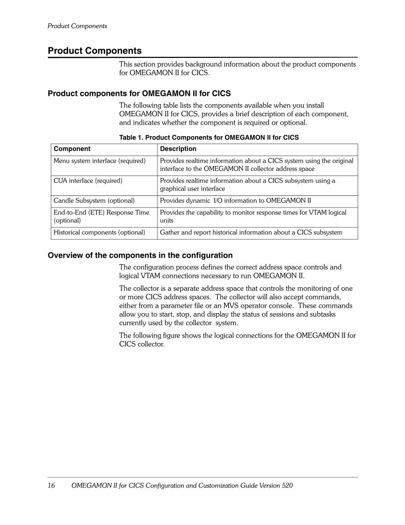
Product components for OMEGAMON II for CICSThe following table lists the components available when you install OMEGAMON II for CICS, provides a brief description of each component, and indicates whether the component is required or optional.
Overview of the components in the configurationThe configuration process defines the correct address space controls and logical VTAM connections necessary to run OMEGAMON II.
The collector is a separate address space that controls the monitoring of one or more CICS address spaces. The collector will also accept commands, either from a parameter file or an MVS operator console. These commands allow you to start, stop, and display the status of sessions and subtasks currently used by the collector system.
The following figure shows the logical connections for the OMEGAMON II for CICS collector.
Table 1. Product Components for OMEGAMON II for CICS
Component Description
Menu system interface (required) Provides realtime information about a CICS system using the original interface to the OMEGAMON II collector address space
CUA interface (required) Provides realtime information about a CICS subsystem using a graphical user interface
Candle Subsystem (optional) Provides dynamic I/O information to OMEGAMON II
End-to-End (ETE) Response Time (optional)
Provides the capability to monitor response times for VTAM logical units
Historical components (optional) Gather and report historical information about a CICS subsystem

Background about Components and Modes of Operation 17
Product Components
FIGURE 1. Logical Connections for the OMEGAMON II for CICS Collector
Note: The default value for the started task in the figure has changed.
The CUA interface address space controls the CUA display and analysis processes. It is controlled and configured by a set of runtime libraries. The CUA interface address space must be started, along with the collector address space, in order to provide the OMEGAMON II for CICS CUA environment.
The following figure shows the logical connections for the OMEGAMON II for CICS CUA Interface.
FIGURE 2. Logical Connections for the OMEGAMON II for CICS CUA Interface
Note: The started task names in the figure have changed.

Details about the User Interfaces
18 OMEGAMON II for CICS Configuration and Customization Guide Version 520
Details about the User InterfacesThe OMEGAMON II collector provides two user interfaces, the menu system interface and the Common User Access (CUA) interface.
In order to use the menu system or CUA interface, you must customize
� the OMEGAMON II operating mode (or modes) you choose
� the CICS tables and JCL
� the Global Data Area (performed with CICAT)
� menu system security (performed with CICAT)
� System Management Facility (SMF) requirements
Menu system interfaceThe menu system is the original interface to the OMEGAMON II collector address space. The menu system and collector are contained within the same address space. The menu system is one user interface to the collector; the CUA interface is the other. When you use the conventional menus and panels of the menu system interface, you have a comprehensive set of functions for analyzing your CICS system.
You can use the menu system in any of the operating modes. See “Modes of Operation” on page 53.
To use the menu system interface, you may want to customize
� menu system profiles (optional)
� third-party product support (optional)
� umbrella transaction support (optional)
For more information about the menu system, see the OMEGAMON II for CICS Reference Manual.
CUA interfaceAccessed directly or through OMEGAVIEW, the CUA interface provides a comprehensive set of functions for analyzing your CICS system, just as the menu system interface provides. We recommend the CUA interface, however, because it is easier to use. The CT/Engine component drives the CUA interface, which is the second interface to the collector.
With its CUA-compliant panels, color-coded status lights, and point-and-shoot navigation facility, the CUA interface is ideally suited for monitoring CICS regions and responding to a problem as soon as it occurs.
Recommendation
You should customize the menu system interface before you customize the CUA interface.

Background about Components and Modes of Operation 19
Details about the User Interfaces
The CUA interface complies with the IBM SAA/CUA (Systems Application Architecture/Common User Access) guidelines, which promote ease of use in software interfaces.
The CUA interface uses a virtual terminal to access the menu system in VTAM mode.
In the CUA interface, you can customize
� CUA profiles
� CUA security
For more information about the CUA interface, see the following documents:
� OMEGAMON II for CICS Reference Manual
� OMEGAMON II for CICS User’s Guide
� Common User Access: Basic Interface Design Guide (IBM manual)
Details about the Candle Subsystem
20 OMEGAMON II for CICS Configuration and Customization Guide Version 520
Details about the Candle Subsystem
IntroductionThis section provides background information about the Candle Subsystem.
Candle Subsystem componentThe Candle Subsystem is an MVS subsystem that enables OMEGAMON II to monitor dynamic device activity in MVS/ESA™ SP4 and higher.
When installed, the Candle Subsystem runs in its own address space, providing dynamic I/O device information to OMEGAMONs running in other address spaces.
Sharing the Candle SubsystemYou only need one Candle Subsystem for an MVS system image. A single Candle Subsystem can support multiple copies of OMEGAMON II and multiple OMEGAMON II products on a single MVS image.
The subsystem ID identifies a copy of the Candle Subsystem. To use the same Candle Subsystem for all OMEGAMON II runtime environments on a single MVS image, Candle recommends that you specify the same subsystem ID during the configuration of each OMEGAMON II product. The Candle default subsystem ID is CNDL.
System requirementsThe Candle Subsystem has the following system requirements:
� The Candle Subsystem requires 4K of ECSA.
� The Candle Subsystem must be defined to MVS as a subsystem.
� The initialization module, KCNDLINT, must reside in a link list authorized library.
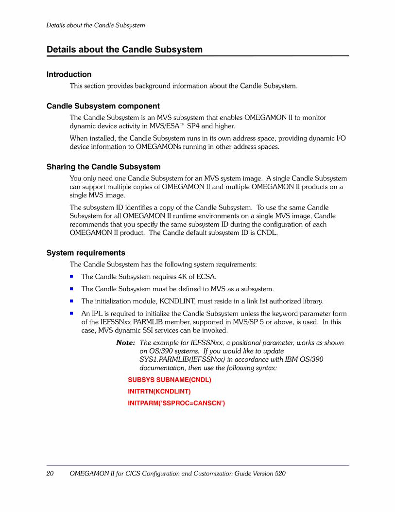
� An IPL is required to initialize the Candle Subsystem unless the keyword parameter form of the IEFSSNxx PARMLIB member, supported in MVS/SP 5 or above, is used. In this case, MVS dynamic SSI services can be invoked.
Note: The example for IEFSSNxx, a positional parameter, works as shown on OS/390 systems. If you would like to update SYS1.PARMLIB(IEFSSNxx) in accordance with IBM OS/390 documentation, then use the following syntax:
SUBSYS SUBNAME(CNDL)
INITRTN(KCNDLINT)
INITPARM(‘SSPROC=CANSCN’)

Background about Components and Modes of Operation 21
Details about the Candle Subsystem
Starting the Candle Subsystem automaticallyMember rhilev.RKANSAM(CANSCN) contains a sample JCL procedure for creating the Candle Subsystem. You can modify this to fit your configuration standards, and then copy it to a system procedure library.
If you want the Candle Subsystem address space to be started automatically at system IPL, then the name given to the JCL procedure must match the value of the SSPROC keyword in the IEFSSNxx member of SYS1.PARMLIB.
Determining whether or not to install the Candle SubsystemYou should migrate from your current Candle Subsystem to the current version. This will ensure that new PTF maintenance gets properly installed. However, a prior version is currently compatible with V520 of the OMEGAMONs and other Generally Available (GA) products. For example, you can use V500 of the Candle Subsystem with V520 of OMEGAMON II for MVS.
The latest version of the Candle Subsystem, V500, can be used with earlier versions (GA-1) of the OMEGAMON products. For example, V500 of the Candle Subsystem can be used with V400 or an OMEGAMON II product.
If you have installed another OMEGAMON II product at your site, at the same level as shipped with the OMEGAMON II product you are currently installing, you may have already installed the Candle Subsystem.

Modes of Operation
22 OMEGAMON II for CICS Configuration and Customization Guide Version 520
Modes of OperationThis section provides background information about operating modes.
During configuration, you will be asked to select and customize an operating mode. Available operating modes are:
� VTAM mode
� TSO/ISPF mode
� dedicated mode
VTAM mode is required to run the CUA interface. To install support for the OMEGAMON II modes of operation for the menu system interface see “Modes of Operation” on page 53.
Illustration showing the relationship for the modes of operationThe following graphic shows the relationship of OMEGAMON II components in VTAM, TSO/ISPF, and dedicated modes.
FIGURE 3. Relationship of Components in VTAM, TSO/ISPF, and Dedicated Modes

Background about Components and Modes of Operation 23
Modes of Operation
Operating mode characteristics and requirementsThe following table describes each operating mode and its requirements.
Table 2. Characteristics and Requirements for OMEGAMON II Modes of Operation
Mode Characteristics Configuration Requirements
VTAM VTAM mode enables you to run OMEGAMON II sessions from a VTAM terminal without an intermediate online application, such as TSO. You can set automatic update mode so that the screen refreshes automatically.
VTAM mode allows all VTAM terminal users to share a single copy of OMEGAMON II.
Define a VTAM applid for OBVTAM.
TSO and ISPF The TSO address space communicates with the OMEGAMON II address space via a VTAM application, VTM1. In this mode there is no auto screen refresh; the screen refreshes when you press the Enter key. TSO mode enables you to access OMEGAMON II without logging off TSO.
ISPF mode includes split-screen capability that lets you swap between multiple OMEGAMON II sessions, or between OMEGAMON II and another ISPF application.
� Define a VTAM applid for OBVTAM.
� Requires an active OBVTAM application.
� Define a set of virtual terminals to VTAM. You can define up to 99 virtual terminals in the virtual terminal pool (VTPOOL).
Dedicated Dedicated mode offers high availability and does not require VTAM services. Dedicated mode uses EXCP to communicate with a terminal and refreshes the screen every few seconds.
Dedicated mode allows OMEGAMON II to provide realtime data even when VTAM is not available.
Availability of a locally attached non-SNA terminal.

Modes of Operation
24 OMEGAMON II for CICS Configuration and Customization Guide Version 520
Installing, Configuring, and Customizing OMEGAMON II for CICS 25
Installing, Configuring, and CustomizingOMEGAMON II for CICS
Chapter OverviewThis chapter provides information about installing, configuring, and customizing the product.
Chapter ContentsConfiguration Planning and Considerations . . . . . . . . . . . . . . . . . . . . . . . 27Overview of the Process . . . . . . . . . . . . . . . . . . . . . . . . . . . . . . . . . . . . . . 33CICAT Background and Requirements . . . . . . . . . . . . . . . . . . . . . . . . . . . 35CICAT Installation Procedure . . . . . . . . . . . . . . . . . . . . . . . . . . . . . . . . . . 36CICAT Configuration Procedures . . . . . . . . . . . . . . . . . . . . . . . . . . . . . . . 37Manual Configuration Procedures. . . . . . . . . . . . . . . . . . . . . . . . . . . . . . . 40Manual Customization Procedures . . . . . . . . . . . . . . . . . . . . . . . . . . . . . . 41
2

Information Covered in this Chapter
26 OMEGAMON II for CICS Configuration and Customization Guide Version 520
Information Covered in this ChapterThis chapter provides:
� the considerations you should review before you begin to configure and customize OMEGAMON II for CICS
� a broad overview of the installation, configuration, and customization process (as well as where you can locate the information you will need)
� background about the Candle Installation and Configuration Assistance Tool (CICAT)
� an overview of how you install the product using CICAT
� an overview of how you configure the product using CICAT and a checklist listing the steps for the CICAT configuration procedure
� a checklist listing the steps for the manual configuration procedures
� a checklist listing the steps for the manual customization procedures
If you are installing the product for the first time or you need a reminder about the different components and modes of operation for the product, see the chapter “Background about Components and Modes of Operation” on page 15.

Installing, Configuring, and Customizing OMEGAMON II for CICS 27
Configuration Planning and Considerations
Configuration Planning and ConsiderationsThis section provides the considerations you must review before you begin configuring and customizing OMEGAMON II for CICS.
Software prerequisitesFor information about the software required or supported for OMEGAMON II for CICS, see the Installing Candle Products on MVS manual.
Requirements for virtual storageThe following tables provides information to help you determine how much virtual storage OMEGAMON II will use once it is installed and operating in either the menu system interface or the CUA interface.
Note: The CUA interface itself has no direct Common Service Area (CSA) or Extended Common Service Area (ECSA) requirements.
Use Table 3 to determine the storage required in CSA and ECSA. If you are running CICS under MVS/XA, you must also determine the additional storage necessary as described in Table 4 .
Use Table 4 to determine additional storage in ECSA only if you are monitoring CICS running under MVS/XA.
Table 3. Storage Required in CSA and ECSA
Function CSA required You require...
ECSA required
You require...
Storage is freed when...
Each collector Approximately 1 K
each collector is terminated
Each CICS region you monitor
Approximately.5 K
monitoring is stopped
Table 4. Storage Required for Monitoring CICS under MVS/XA
Function ECSA Required
You require...
Storage is freed when...
Each CICS release level you monitor Approximately130 K
monitoring is stopped
Each OMEGAMON II session Approximately3 K
session is terminated

Configuration Planning and Considerations
28 OMEGAMON II for CICS Configuration and Customization Guide Version 520
Use Table 5 to determine the amount of CICS storage that is required the first time OMEGAMON II is activated within a CICS region.
Each task currently running uses Approximately 1.5 K for CICS/MVS and for CICS/ESA Approximately 1 K of DSA, and Approximately .2 K of EDSA.
Notes:
1. Use the calculation below to help you determine approximate buffer storage requirements (buffer size) for task history and the response time collector:
buffer size = (1+(n/300))*1200 + n*1200 + 88
where n is the number of records you want the buffer to contain. (You will set the number of buffer records when you specify the monitoring options for the product using the Global Data Area.)
2. OMEGAMON II allocates buffers of 64 kilobytes to contain the file-level statistics it collects during the CICS transactions. OMEGAMON II uses 50–150 bytes per task for each file that a task accesses. OMEGAMON II retains this storage for the lifetime of the task and reuses it when the task terminates.
Table 5. Storage Required in CICS
Usage Private Extended Private DSA EDSA
Static Approximately 150 K
Approximately 6 K Approximately 10 K
Buffer for task history and response time collector data
Variable (see Note #1 below)
Buffer for file-level statistics Variable (see Note #2 below)

Installing, Configuring, and Customizing OMEGAMON II for CICS 29
Configuration Planning and Considerations
Cross-memory considerationsThe collector reserves a system linkage index for cross-memory use.
Although the linkage index is reused by subsequent invocations of the collector within an IPL, you should note that because of cross-memory linkages, address spaces used by the menu system will be marked as non-reusable by MVS upon termination of the address space. Any address space marked as non-reusable because the menu system interface has terminated will not be available again within the same IPL.
Users running MVS/ESA 4.3 or later will lose the address space ID (ASID) because a space-switch PC routine is used within OMEGAMON II. MVS will mark the ASID as unusable to maintain system integrity.
You can increase the value of the IEASYSxx RSVNONR parameter (the default is 5) in SYS1.PARMLIB. This will reserve ASIDs, which can be used to replace any address spaces marked as non-reusable due to cross-memory linkages.
Basic system configurationConfiguring OMEGAMON II creates a set of address spaces independent of your existing CICS regions. So that no invasive processes will be installed into any CICS system, the basic system that you will configure will not include the following functions:
� response time collection
� end-to-end response time (ETE)
� task history collection
� internal bottleneck collection
� interval record collection
� resource limiting
To enable the above functions, follow the instructions in “Modifying the CICS Tables and JCL” on page 65.
Simplified signon considerationsFor a region to be included on the CICS Regions panel:
� OMEGAMON II for CICS must be initialized in the CICS region by executing program KOCOME00 in the PLTPI or by executing transaction OMEG INIT.
� The CICS region must reside in the same MVS image as the address space for the CUA interface.
� When the CUA function level security is enabled, the current user must be authorized to monitor that region.

Configuration Planning and Considerations
30 OMEGAMON II for CICS Configuration and Customization Guide Version 520
Dispatching priorityTo ensure availability, you must execute OMEGAMON II with an MVS dispatching priority higher than any CICS region being monitored. OMEGAMON II will attempt to raise its dispatching priority above that of the target CICS region. If this is not possible, OMEGAMON II produces the following message:
OC0830 OCRO CAUTION DISPATCHING PRIORITY GREATER THAN 239
Running OMEGAMON II at a lower dispatching priority than the target CICS region, especially while you are collecting response time data, can seriously degrade the overall performance of your system. Running OMEGAMON II at a lower dispatching priority affects both the collector and the CUA interface.
You can set the dispatching priority and performance goals of your OMEGAMON II address space in the IEAICScc and IEAIPScc members of SYS1.PARMLIB.
MVS/ESA 5.1 considerationsMVS/ESA Version 5.1 introduces new modes of workload management, controlled by the workload manager. In compatibility mode, operation is identical to that of previous releases of MVS/ESA; existing SRM algorithms control the performance of the system.
However, in goal mode, the OMEGAMON II address spaces may not be maintained at a dispatching priority higher than the target CICS address space. If this occurs, message OC0830, mentioned above, will not be issued. Refer to the MVS/ESA V5.1 Planning: Workload Management manual for a detailed discussion of the new mode of operation. We suggest that you review information on velocity.
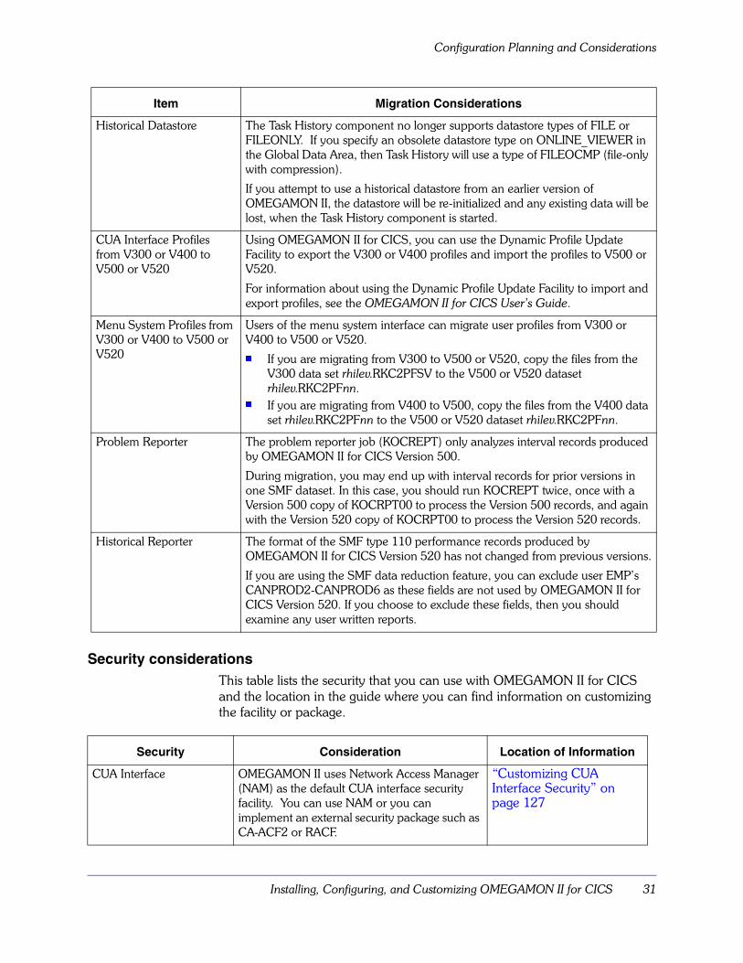
Migration considerationsThe following table lists the elements you can migrate from prior versions of OMEGAMON II for CICS.
Item Migration Considerations
Global Data Area The Global Data Area contains the parameters that control the OMEGAMON II monitoring options. The values in these parameters apply to all sessions that are monitoring the same CICS region. A default global data module is shipped with the product.
You can install and migrate the current release level, or change the defaults using “Specifying the Monitoring Options for the Product” on page 79.
Installing, Configuring, and Customizing OMEGAMON II for CICS 31
Configuration Planning and Considerations
Security considerationsThis table lists the security that you can use with OMEGAMON II for CICS and the location in the guide where you can find information on customizing the facility or package.
Historical Datastore The Task History component no longer supports datastore types of FILE or FILEONLY. If you specify an obsolete datastore type on ONLINE_VIEWER in the Global Data Area, then Task History will use a type of FILEOCMP (file-only with compression).
If you attempt to use a historical datastore from an earlier version of OMEGAMON II, the datastore will be re-initialized and any existing data will be lost, when the Task History component is started.
CUA Interface Profiles from V300 or V400 to V500 or V520
Using OMEGAMON II for CICS, you can use the Dynamic Profile Update Facility to export the V300 or V400 profiles and import the profiles to V500 or V520.
For information about using the Dynamic Profile Update Facility to import and export profiles, see the OMEGAMON II for CICS User’s Guide.
Menu System Profiles from V300 or V400 to V500 or V520
Users of the menu system interface can migrate user profiles from V300 or V400 to V500 or V520.� If you are migrating from V300 to V500 or V520, copy the files from the
V300 data set rhilev.RKC2PFSV to the V500 or V520 dataset rhilev.RKC2PFnn.
� If you are migrating from V400 to V500, copy the files from the V400 data set rhilev.RKC2PFnn to the V500 or V520 dataset rhilev.RKC2PFnn.
Problem Reporter The problem reporter job (KOCREPT) only analyzes interval records produced by OMEGAMON II for CICS Version 500.
During migration, you may end up with interval records for prior versions in one SMF dataset. In this case, you should run KOCREPT twice, once with a Version 500 copy of KOCRPT00 to process the Version 500 records, and again with the Version 520 copy of KOCRPT00 to process the Version 520 records.
Historical Reporter The format of the SMF type 110 performance records produced by OMEGAMON II for CICS Version 520 has not changed from previous versions.
If you are using the SMF data reduction feature, you can exclude user EMP’s CANPROD2-CANPROD6 as these fields are not used by OMEGAMON II for CICS Version 520. If you choose to exclude these fields, then you should examine any user written reports.
Security Consideration Location of Information
CUA Interface OMEGAMON II uses Network Access Manager (NAM) as the default CUA interface security facility. You can use NAM or you can implement an external security package such as CA-ACF2 or RACF.
“Customizing CUA Interface Security” on page 127
Item Migration Considerations

Configuration Planning and Considerations
32 OMEGAMON II for CICS Configuration and Customization Guide Version 520
Historical reporting considerationsThis table lists the considerations for the elements in historical reporting and provides the location in this guide where you can find additional information.
Considerations for End-to-End (ETE)All of the OMEGAMON products that use ETE Version 500 run on one ETE system. For each OMEGAMON that uses ETE, the ETE proc is installed into your PROCLIB during CICAT configuration.
Candle recommends that your OMEGAMONs share the same ETE started task.
If some OMEGAMON systems require ETE Version 500 and some require an ETE release prior to Version 160, you will need to run two ETE systems.
See the End-to-End: Response Time Feature Reference Manual for more information.
Menu System OMEGAMON II uses an internal security feature as the default menu system security facility. For an added level of security, you can set up an interface between OMEGAMON II and an external security package such as CA-ACF2 or RACF.
“Menu System Security Facility” on page 161
Function Level OMEGAMON II lets you restrict access, by user, to functions within the CUA component using an external security manager like CA-ACF2 or RACF.
“Function Level Security” on page 137
CA-ACF2 OMEGAMON II lets you use CA-ACF2 Version 5.0 and above as a security package. If your site uses DL/I with CICS 2.1.2, and you use CA-ACF2 for security, specify the following in the ACF2 parameter dataset:
INTERCEPT=DIRECT
“CA-ACF2 CUA interface security” on page 131
Element of Historical Reporting
Consideration Location of Information
Global Data Area The Global Data Area lets you set options for the task history collector and the historical reporter.
“Specifying the Monitoring Options for the Product” on page 79
CICS Connection Initialization
To enable the task history collector, there must be a connection between OMEGAMON II and the CICS region you intend to monitor.
“Initializing the CICS Connection” on page 106
SMF Logging You specify all the options for SMF logging using the Global Data Area.
“SMF Considerations” on page 195
Security Consideration Location of Information

Installing, Configuring, and Customizing OMEGAMON II for CICS 33
Overview of the Process
Overview of the ProcessThis section provides a broad overview of the installation, configuration, and customization process. It also includes information about accessing help when using CICAT.
Broad overview of the processThe following table contains the broad steps you follow when you install, configure, and customize the product. The table also shows where you can find the information you will need during each of the steps.
Table 6. Overview of the Process
Step Action Information
1 Using CICAT, install the product and create any new runtime environments.
Installing Candle Products on MVS and the online help for the product panel you are using
2 Using CICAT, configure the components you want to use.
Online help for the product panel you are using
4 Manually configure the components and verify that the configuration is complete.
Chapter 3
5 Manually customize the components you want to use.
Chapters 4 through 16 in this guide
Getting Help with CICAT
34 OMEGAMON II for CICS Configuration and Customization Guide Version 520
Getting Help with CICATThe help for CICAT contains detailed information about using the CICAT panels. For example, the help contains information about:
� how to use the panel
� why parameters are required
� what the available action codes provide
� what the input fields mean
� what you are required to supply
To display help from any CICAT panel, press the Help key (F1) or enter HELP on the command line.
You can also display help for the help. For example, you can display information about the command to use to return to the previous topic in the help system. To display the help for help from any help panel, press the Help key (F1) or enter HELP on the command line.

Installing, Configuring, and Customizing OMEGAMON II for CICS 35
CICAT Background and Requirements
CICAT Background and RequirementsThis section describes using the Candle Installation and Configuration Assistance Tool (CICAT).
You must use CICAT to install and configure the product. CICAT is an ISPF dialog that guides you through the installation and configuration steps required to install this product. Data entry panels assist you in understanding your site-specific parameter values. Associated help panels assist you in understanding the CICAT process and describe the input fields on the entry panels.
CICAT is restartable. If necessary, you can end the dialog, start it again, and continue from the point of interruption. ISPF V2.3 or above is required to use CICAT.
If you have not previously installed CICAT during installation of this or any other Candle product, you must do so now. For instructions on installing CICAT, see the Installing Candle Products on MVS manual. If you want to use CICAT from a previous installation, you must ensure that it is the most
current version of CICAT. The Installing Candle Products on MVS manual will help you make this determination.
Restrictions on specifying values in CICATImportant Note: Entering ampersand (&) in any CICAT parameter string, whether you are in interactive or batch mode, results in a CICAT abend.
Reminder about the information availableIf you need information about installing the product using CICAT, you can locate information in the
� Installing Candle Products on MVS manual
� online help for the product panel you are using
Examples of the tasks performed by CICATCICAT performs tasks that make the product operational with a basic set of defaults. You use CICAT to:
� modify JCL
� allocate datasets
� define VTAM applids
� create task history datasets
� create runtime libraries
� install the Candle Subsystem

CICAT Installation Procedure
36 OMEGAMON II for CICS Configuration and Customization Guide Version 520
CICAT Installation ProcedureThis section provides information about the CICAT installation process, including information on
� selecting products to configure
� managing your runtime environment
Overview of the installation process using CICATThe following is an overview of how you select products to configure and manage your runtime environment.
1. Invoke CICAT.
2. Select from the CICAT Main Menu as follows:� If installing a standalone product, select the item for the product.
� If installing from a multi-product quick install tape, select the item MultiProduct Quick Install, nnnn level.
3. Ensure that installation and maintenance is completed before starting configuration.
4. Select Assist Configuration.
5. If a target RTE has not already been defined, use action code A (Add) to define an RTE.
6. Use action B (Build) to allocate runtime libraries.
7. Use action code C (Configure) to invoke configuration of an RTE.
8. Select a product to configure.� If you selected a single-component product on the CICAT Main Menu, the
product configuration menu appears and you can proceed to configure.
� If you selected a multi-component product, a list of components appears. Select and configure each component in the order presented.
� If you selected a multi-product quick install tape, a list of products and components found on the tape appears. Select and configure each product/component in the order presented.
9. If you want to configure another product and it is not part of a quick install tape, return to the initial CICAT menu, select the product, and return to step 4 to select Assist Configuration.
10. When you are finished configuring all the products you want in an RTE, return to the Runtime Environments panel and use action code L (Load) to load the runtime libraries.
11. You can now proceed to verify and customize the products you configured in your RTE.

Installing, Configuring, and Customizing OMEGAMON II for CICS 37
CICAT Configuration Procedures
CICAT Configuration ProceduresThis section describes the CICAT configuration procedures for OMEGAMON II for CICS.
Prerequisites for configuring OMEGAMON II for CICSBefore you start to configure OMEGAMON II for CICS, be sure that you have reviewed the considerations and planning information in the section “Configuration Planning and Considerations” on page 27.
The following configuration procedures assume that you have:
�Completed SMP/E installation and applied maintenance for the product, or for the product, as described in your Installing Candle Products on MVS manual.
Reminder about the information availableIf you need information about configuring OMEGAMON II for CICS using CICAT or specific information about the values you specify using CICAT, see the online help for the product panel you are using.
Accessing the Configure OMEGAMON II for CICS menuTo begin the product configuration:
1. Start CICAT. (For a reminder, see your Installing Candle Products on MVS manual.)
2. On the CICAT Main Menu:� If you installed the MultiProduct Quick Install tape, select MultiProduct
Quick Install.
To preview the list of products included in your MultiProduct Quick Install tape, you can use action code V (View Additional Information) on MultiProduct Quick Install.
� If you installed the product as a separate product, select it.
3. On the Installation/Configuration Primary Menu, select Assist Configuration.
4. On the Runtime Environments panel, use action code C (Configure) on the RTE you are ready to configure.
5. If you installed the MultiProduct Quick Install tape or a multicomponent product, select the product on the Product Configuration Selection Menu.
6. Proceed to use the Configure Product Name Menu.

CICAT Configuration Procedures
38 OMEGAMON II for CICS Configuration and Customization Guide Version 520
Example of the Configure OMEGAMON II for CICS menu in CICATThe following figure is an example of the Configure OMEGAMON II for CICS menu.
CICAT configuration checklistThe following table contains the steps you perform on the CICAT Configure OMEGAMON II for CICS menu. The steps are listed in the sequence in which they are to be performed. Use the � column to check off steps as you complete them.
Table 7. CICAT Configuration Procedure Checklist
� CICAT Configuration Step
Use Specify configuration values to specify VTAM information, CUA security options, optional started tasks, advanced options, and OMEGAMON II for CICS menu system/Engine pairs for the current runtime environment.
Use Allocate additional runtime datasets to review the JCL that CICAT generates to allocate other required libraries in addition to the standard set of runtime datasets.
Use Create runtime members to:� review the JCL that CICAT generates to create the members for the interfaces for the realtime
monitor� select the CICS IDs that you want CICAT to install in the RTE and review the JCL that CICAT
generates
If you want to create a task history dataset to retain historical task records, use Allocate/initialize task history datasets. (This step is optional.)
---------------- CONFIGURE OMEGAMON II FOR CICS / RTE: RTE NAME-----------OPTION ===>
Last selectedPerform these configuration steps in order: Date Time
1 Specify configuration values2 Allocate additional runtime datasets3 Create runtime members4 Complete the configuration
Optional:
5 Allocate/initialize task history datasets6 Install/update CICS global data area modules7 Modify menu system command security8 Install Candle Subsystem
F1=Help F3=Back
Installing, Configuring, and Customizing OMEGAMON II for CICS 39
CICAT Configuration Procedures
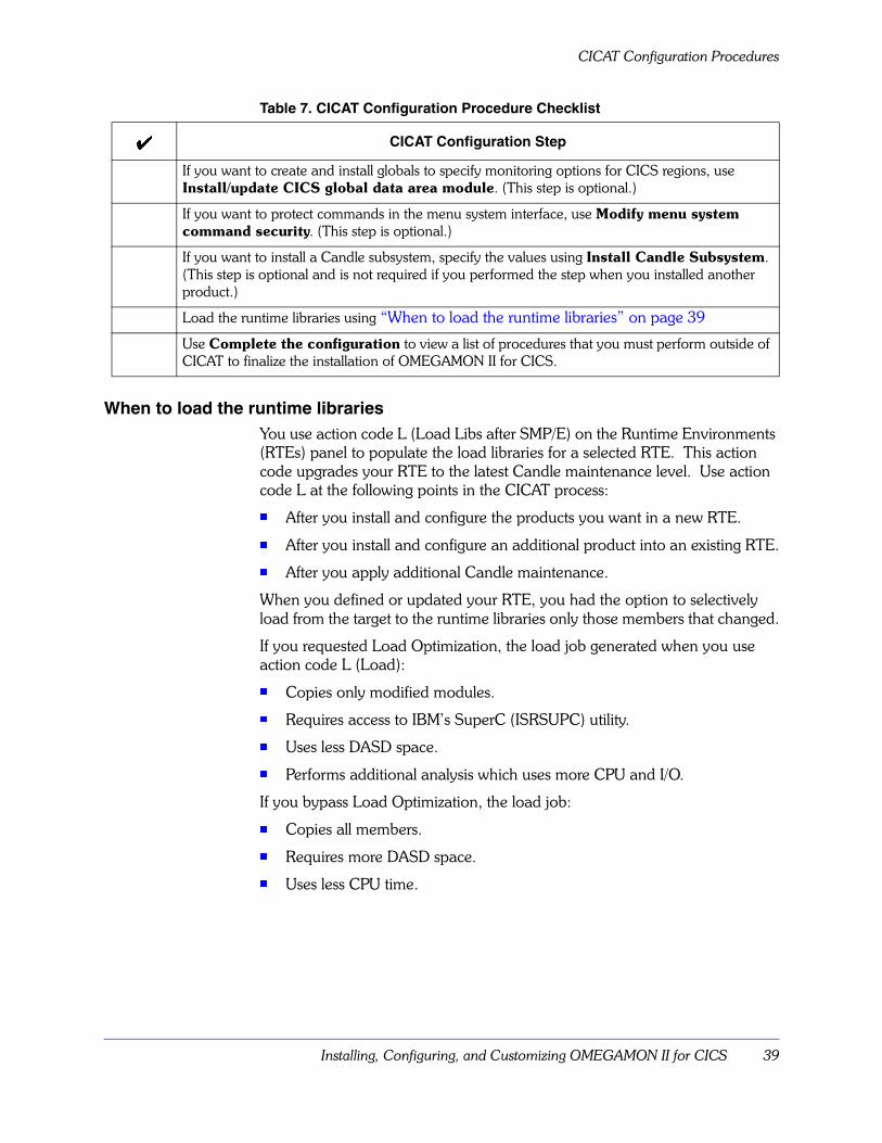
When to load the runtime librariesYou use action code L (Load Libs after SMP/E) on the Runtime Environments (RTEs) panel to populate the load libraries for a selected RTE. This action code upgrades your RTE to the latest Candle maintenance level. Use action code L at the following points in the CICAT process:
� After you install and configure the products you want in a new RTE.
� After you install and configure an additional product into an existing RTE.
� After you apply additional Candle maintenance.
When you defined or updated your RTE, you had the option to selectively load from the target to the runtime libraries only those members that changed.
If you requested Load Optimization, the load job generated when you use action code L (Load):
� Copies only modified modules.
� Requires access to IBM’s SuperC (ISRSUPC) utility.
� Uses less DASD space.
� Performs additional analysis which uses more CPU and I/O.
If you bypass Load Optimization, the load job:
� Copies all members.
� Requires more DASD space.
� Uses less CPU time.
If you want to create and install globals to specify monitoring options for CICS regions, use Install/update CICS global data area module. (This step is optional.)
If you want to protect commands in the menu system interface, use Modify menu system command security. (This step is optional.)
If you want to install a Candle subsystem, specify the values using Install Candle Subsystem. (This step is optional and is not required if you performed the step when you installed another product.)
Load the runtime libraries using “When to load the runtime libraries” on page 39
Use Complete the configuration to view a list of procedures that you must perform outside of CICAT to finalize the installation of OMEGAMON II for CICS.
Table 7. CICAT Configuration Procedure Checklist
� CICAT Configuration Step

Manual Configuration Procedures
40 OMEGAMON II for CICS Configuration and Customization Guide Version 520
Manual Configuration ProceduresThis section provides information about performing manual configuration procedures for the product.
Reminder about the information availableThe checklist in the following table contains the location where you can find the information you will need.
Manual configuration checklistThe following table contains the steps you perform manually to configure OMEGAMON II for DB2. The steps are listed in the sequence in which they are to be performed. Use the �� column to check off steps as you complete them.
Table 8. Manual Configuration Procedure Checklist
� Manual Configuration Step
Copy started task procedures to your started task library using “Copying procedures to started task library” on page 44
APF-authorize libraries using “APF-authorizing libraries” on page 44.
Add ETE to the proclib using “Adding ETE to the PROCLIB” on page 45.
Give OMEGAMON II for CICS started tasks access to the high-level qualifier using “Giving Started Tasks Access to High-level Qualifier” on page 46.
Verify the installation and configuration using “Verifying Installation and Configuration” on page 47.

Installing, Configuring, and Customizing OMEGAMON II for CICS 41
Manual Customization Procedures
Manual Customization ProceduresThis section provides information about performing manual customization procedures for the product.
Reminder about the information availableThe checklist in the following table contains the location where you can find the information you will need.
Manual customization checklistThe following table contains the steps you perform manually to customize the product. The steps are listed in the sequence in which they are to be performed. Use the ��column to check off steps as you complete them. Candle recommends that you review the entire process before you begin customizing the product.
Table 9. Manual Customization Procedures Checklist
� Manual Customization Step
Customize the modes of operation you require using “Modes of Operation” on page 53.
Modify the CICS tables and JCL using “Modifying the CICS Tables and JCL” on page 65.
Start and stop the CUA interface, and log on and off the menu interface using “Starting the CUA Interface (Optional)” on page 105.
Customize CUA interface profiles using “Customizing CUA Interface Profiles” on page 121.
Customize CUA interface security using “Customizing CUA Interface Security” on page 127.
Customize function-level security using “Function Level Security” on page 137.
Customize menu system interface profiles using “Customizing Menu System Interface Profiles” on page 145.
Customize menu system interface security using “Menu System Security Facility” on page 161.
Determine SMF requirements, and start and stop record keeping using “SMF Considerations” on page 195.
Implement the optional support for third-party database or fourth-generation language products using “Installing Third-Party Support” on page 207.
Implement the optional support for umbrella transactions using “Umbrella Transaction Services” on page 221.

Manual Customization Procedures
42 OMEGAMON II for CICS Configuration and Customization Guide Version 520
Completing the Configuration 43
Completing the Configuration
Chapter OverviewTo run OMEGAMON II for CICS, after installation and CICAT configuration, you must perform the additional tasks described in this chapter.
These tasks include:
� copying procedures created by CICAT to your started task library
� copying VTAM definitions created by CICAT to VTAMLST
� APF-authorizing libraries
� adding ETE to the PROCLIB
� verifying installation and configuration
Chapter ContentsCopying to System Libraries . . . . . . . . . . . . . . . . . . . . . . . . . . . . . . . . . . . 44Adding ETE to the PROCLIB . . . . . . . . . . . . . . . . . . . . . . . . . . . . . . . . . . 45Giving Started Tasks Access to High-level Qualifier . . . . . . . . . . . . . . . . . . 46
3
Copying to System Libraries
44 OMEGAMON II for CICS Configuration and Customization Guide Version 520
Copying to System LibrariesThis section provides information about copying to system libraries.
Copying procedures to started task libraryCICAT configuration created started task procedures in RKANSAM, which you must copy to your started task library. When you copy, you may rename the procedures to meet your site’s requirements.
Update a proclib in your JES proclib concatenation as follows:
1. Confirm that the Candle Subsystem started task, KCNDL, was copied from RKANSAM to PROCLIB.
2. Copy the address space for the OMEGAMON II for CICS CUA interface from RKANSAM to PROCLIB.
3. Copy the address space for the OMEGAMON II for CICS menu system interface from RKANSAM to PROCLIB.
4. Copy the OMEGAMON II for CICS VTAM node generated by CICAT from RKANSAM to your VTAMLST.
APF-authorizing librariesDuring the configuration of OMEGAMON II, you must APF-authorize the libraries listed below.
� rhilev.RKANMOD
� rhilev.RKANMODL
For more information on APF-authorization, consult with the systems programmer responsible for this task at your site or refer to the IBM product manual for the appropriate release of your MVS system.
Notes:
1. You must ensure that all of the libraries in a concatenation are APF-authorized, or MVS will not reflect the authorization status of modules loaded from the concatenated datasets.
2. If you define a runtime environment (RTE) that uses the SMP libraries, put the following libraries into your system’s APF list:� rhilev.RKANMOD
� thilev.TKANMOD
� thilev.TKANMODL
3. JCL for CICS regions monitored by OMEGAMON II for CICS must be modified to so that all data sets in the RKANMOD allocation are APF authorized . If any dataset in the RKANMOD allocation is not APF authorized, CICS user and system transactions may ABEND after OMEGAMON IIis initialized in the CICS region.

Completing the Configuration 45
Adding ETE to the PROCLIB
Adding ETE to the PROCLIBThe End-to-End Response Time Feature (ETE) is an optional component that allows you to monitor response times for VTAM logical units. If you plan to install ETE, follow these instructions.
Note: You can run only one copy of ETE in an MVS image at the latest available level. The latest level of ETE appears in the preventive service planning documentation delivered with this product. If you are already running the latest level, you can skip this step. Otherwise, copy the member for ETE from rhilev.RKANSAM to the procedure library.

Giving Started Tasks Access to High-level Qualifier
46 OMEGAMON II for CICS Configuration and Customization Guide Version 520
Giving Started Tasks Access to High-level QualifierIf your security system restricts dataset access, you must give the OMEGAMON II for CICS started tasks access to the high-level qualifier for the rhilev datasets.
If your RTE uses SMP libraries, you also need to give access to the high-level qualifier for the thilev datasets.

Completing the Configuration 47
Verifying Installation and Configuration
Verifying Installation and ConfigurationTo verify that OMEGAMON II has been installed and configured correctly you will need to
� verify OMEGAMON II
� verify End-to-End Response Time Feature
� verify the Candle Subsystem
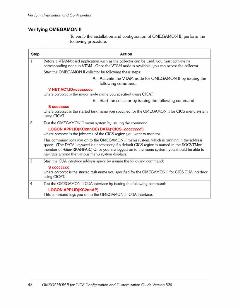
Verifying Installation and Configuration
48 OMEGAMON II for CICS Configuration and Customization Guide Version 520
Verifying OMEGAMON IITo verify the installation and configuration of OMEGAMON II, perform the following procedure.
Step Action
1 Before a VTAM-based application such as the collector can be used, you must activate its corresponding node in VTAM. Once the VTAM node is available, you can access the collector.
Start the OMEGAMON II collector by following these steps:
A. Activate the VTAM node for OMEGAMON II by issuing the following command:
V NET,ACT,ID=ccccccccwhere cccccccc is the major node name you specified using CICAT.
B. Start the collector by issuing the following command:S cccccccc
where cccccccc is the started task name you specified for the OMEGAMON II for CICS menu system using CICAT.
2 Test the OMEGAMON II menu system by issuing the command
LOGON APPLID(KC2nnOC) DATA(‘CICS=cccccccc’)where cccccccc is the jobname of the CICS region you want to monitor.
This command logs you on to the OMEGAMON II menu system, which is running in the address space. (The DATA keyword is unnecessary if a default CICS region is named in the KOCVTMnn member of rhilev.RKANPAR.) Once you are logged on to the menu system, you should be able to navigate among the various menu system displays.
3 Start the CUA interface address space by issuing the following command:
S ccccccccwhere cccccccc is the started task name you specified for the OMEGAMON II for CICS CUA interface using CICAT.
4 Test the OMEGAMON II CUA interface by issuing the following command:
LOGON APPLID(KC2nnAP)This command logs you on to the OMEGAMON II CUA interface.
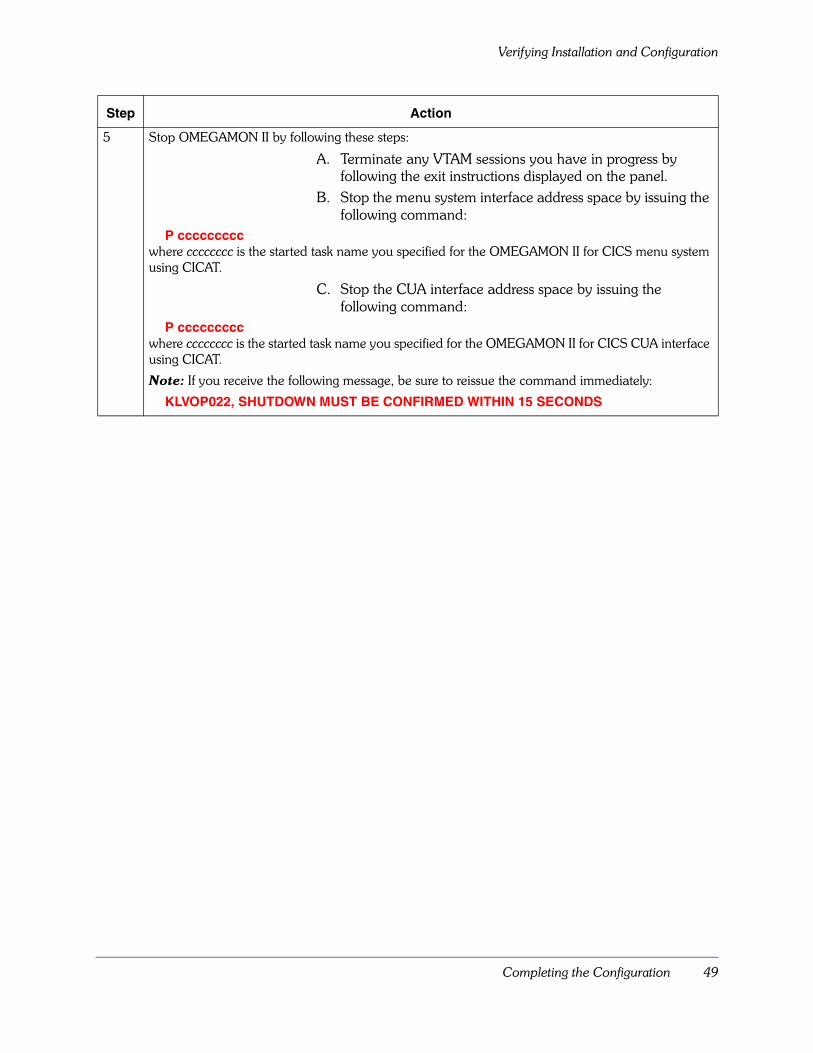
Completing the Configuration 49
Verifying Installation and Configuration
5 Stop OMEGAMON II by following these steps:
A. Terminate any VTAM sessions you have in progress by following the exit instructions displayed on the panel.
B. Stop the menu system interface address space by issuing the following command:
P cccccccccwhere cccccccc is the started task name you specified for the OMEGAMON II for CICS menu system using CICAT.
C. Stop the CUA interface address space by issuing the following command:
P cccccccccwhere cccccccc is the started task name you specified for the OMEGAMON II for CICS CUA interface using CICAT.
Note: If you receive the following message, be sure to reissue the command immediately:
KLVOP022, SHUTDOWN MUST BE CONFIRMED WITHIN 15 SECONDS
Step Action
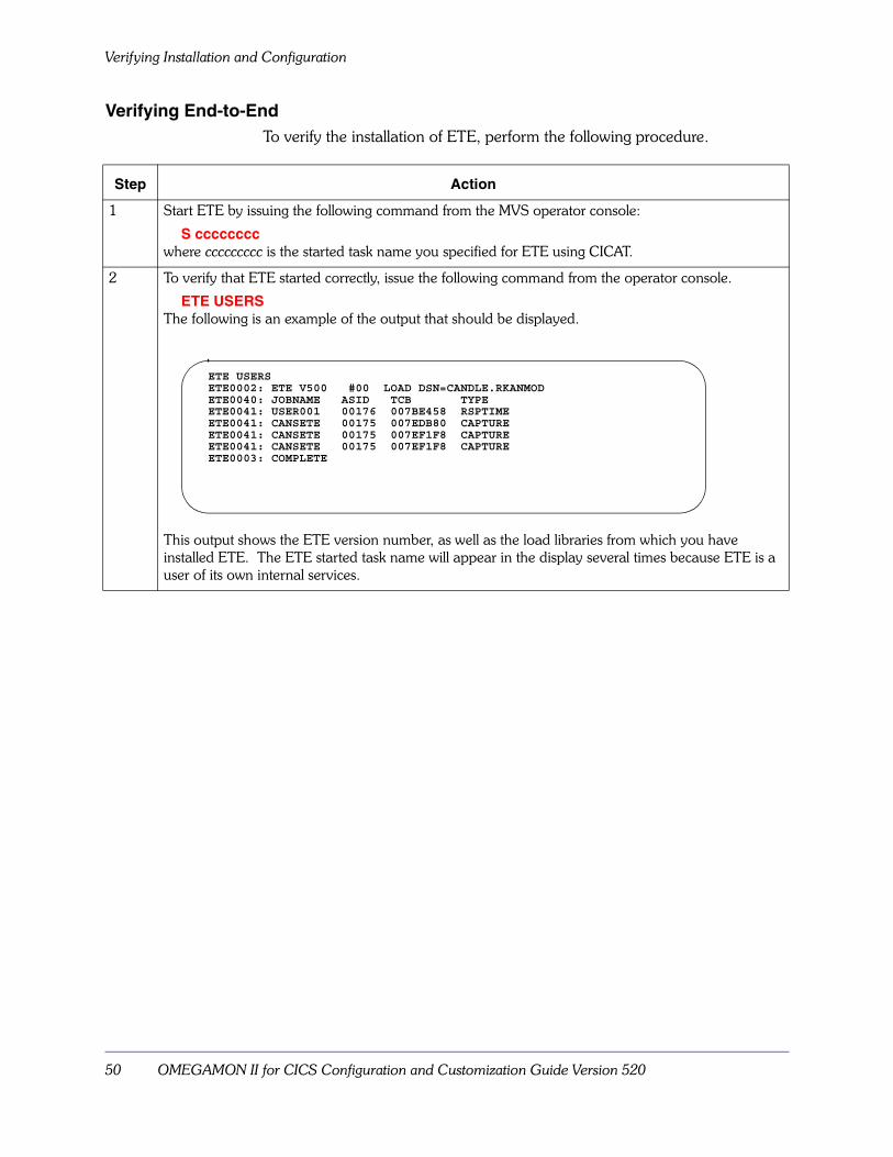
Verifying Installation and Configuration
50 OMEGAMON II for CICS Configuration and Customization Guide Version 520
Verifying End-to-EndTo verify the installation of ETE, perform the following procedure.
Step Action
1 Start ETE by issuing the following command from the MVS operator console:
S ccccccccwhere ccccccccc is the started task name you specified for ETE using CICAT.
2 To verify that ETE started correctly, issue the following command from the operator console.
ETE USERSThe following is an example of the output that should be displayed.
This output shows the ETE version number, as well as the load libraries from which you have installed ETE. The ETE started task name will appear in the display several times because ETE is a user of its own internal services.
ETE USERSETE0002: ETE V500 #00 LOAD DSN=CANDLE.RKANMODETE0040: JOBNAME ASID TCB TYPEETE0041: USER001 00176 007BE458 RSPTIMEETE0041: CANSETE 00175 007EDB80 CAPTUREETE0041: CANSETE 00175 007EF1F8 CAPTUREETE0041: CANSETE 00175 007EF1F8 CAPTUREETE0003: COMPLETE

Completing the Configuration 51
Verifying Installation and Configuration
Verifying the Candle SubsystemTo verify the installation of the Candle subsystem, perform the following procedure. Note that this procedure requires you to IPL your system.
Step Action
1 IPL your system.
2 Check the SYSLOG to be certain that it contains the message CNDL184I.
This message informs you that the Candle subsystem initialization routine has completed. If this message does not appear, check your update to the IEFSSNxx member of SYS1.PARMLIB.
3 Depending on whether you configured your system for automatic startup of the Candle subsystem address space, do one of the following:� If you are configured for automatic startup, check the SYSLOG. You should see messages
CNDL001I, CNDL190I, CNDL034I, and CNDL027I. These confirm that the address space has started.
� If you are not configured for automatic startup, issue the MVS START command. You should see messages CNDL001I, CNDL190I, CNDL034I, and CNDL027I. These confirm that the address space has started.
The format of the MVS START command is
S aaaaaaaawhere aaaaaaaa is the name you have given the Candle subsystem JCL procedure.
4 If necessary, stop the subsystem by issuing the MVS STOP command.
The format of the MVS STOP command is
P aaaaaaaawhere aaaaaaaa is the name you have given the Candle subsystem JCL procedure.

Verifying Installation and Configuration
52 OMEGAMON II for CICS Configuration and Customization Guide Version 520

Modes of Operation 53
Modes of Operation
Chapter OverviewThis chapter explains how to install support for the OMEGAMON II modes of operation for the menu system interface. If you plan to access OMEGAMON II solely through the CUA interface, you may skip this chapter.
Chapter ContentsCustomizing the Modes of Operation . . . . . . . . . . . . . . . . . . . . . . . . . . . . 54Installing in TSO Mode . . . . . . . . . . . . . . . . . . . . . . . . . . . . . . . . . . . . . . . 57Installing in ISPF Mode. . . . . . . . . . . . . . . . . . . . . . . . . . . . . . . . . . . . . . . 60Installing in Dedicated Mode. . . . . . . . . . . . . . . . . . . . . . . . . . . . . . . . . . . 62
4

Customizing the Modes of Operation
54 OMEGAMON II for CICS Configuration and Customization Guide Version 520
Customizing the Modes of OperationYou have already installed OMEGAMON II in VTAM mode during the configuration process. You can now customize your mode of operation in the following ways.
� Modify the VTAM mode (OBVTAM) parameters to meet your site requirements (see page 54).
� Install OMEGAMON II in TSO mode (see page 57).
� Install OMEGAMON II in ISPF mode (see page 60).
� Install OMEGAMON II in dedicated mode (see page 62).
Each of these modes runs under the OMEGAMON II collector. “Collector Address Space” on page 227 gives detailed information about operating the collector.
You can now begin the customization steps required to support each of the modes in which you plan to run OMEGAMON II. You can choose one mode now and install support for additional modes at a later time.
Modifying the OBVTAM parametersUse the following procedure if you want to change any of the default OBVTAM parameters. OBVTAM is a program (or subtask) that allows all VTAM terminal users to share a single copy of OMEGAMON II.
Note: These OBVTAM parameters do not control the CUA interface.
Step Action
1 Using an editor such as ISPF, edit the KOCVTMnn member in the rhilev.RKANPAR dataset, listing the parameters you want for the OBVTAM subtask, which starts the OMEGAMON II. session running under VTAM. Enter a value for every required parameter. If desired, enter values for the optional parameters too. For an explanation of all the possible parameters, including their required or optional status, refer to the list below.
The following example shows some parameters defined for the OBVTAM subtask in the KOCVTMnn member.
START OBVTAM APPL=KOCVTAM, LROWS=99, MODE=IC1, OM=KOCCICS

Modes of Operation 55
Customizing the Modes of Operation
Parameter Required/Optional
Value Description
APPL Required cccccccc Provides the 1- to 8-character name that defines the OBVTAM program as an application to VTAM. You must also specify this name in SYS1.VTAMLST. The default value is KOCVTAM.
AUP Optional YES or NO
Sets automatic update mode when AUP=YES. The default is NO.
CICS Optional cccccccc Names a jobname of a CICS region to monitor if the user does not specify one when logging on to OMEGAMON II. There is no default.
COLS Optional 80, 132, or 160
Specifies the number of columns on the screen. If the values are omitted, the number of columns default to the terminal attributes.
DC Optional YES or NO
Specifies whether OMEGAMON II compresses the 3270 data stream before it is sent to a terminal. The default is NO.
FSCR Optional cccccccc Specifies the first screen space to be displayed. The default is ZMENUI.
LROWS Optional ROWS to 9999
Specifies the number of logical rows. LROWS is always larger than or equal to ROWS. (If you specify an LROWS value that is smaller than the ROWS value, OMEGAMON II uses the ROWS value for LROWS also.) The default is 99.
MODE Required IC1 Specifies the mode in which OMEGAMON II runs. (MODE=IC1 causes OMEGAMON II to run under VTAM.) There is no default.
OM Required KOCCICS Identifies the OMEGAMON II for CICS module. There is no default.
PRTCT Optional cccccccc Provides the password that the OBVTAM program must pass to VTAM when OMEGAMON II is started using VTAM services. This password must match the password associated with VTAM’s definition of OBVTAM. There is no default.
PSWD Optional cccccccc Provides the 1- to 8-character name that you must supply as part of the PSWD parameter on the OMEGAMON II LOGON command if you choose this kind of security for your installation. There is no default.
ROWS Optional nn Specifies the number of physical rows on the screen. The default is 24.
TIMEOUT Optional 0–99 Specifies the number of minutes until OMEGAMON II terminates idle VTAM mode sessions. The value can be any number from 0–99. Specify 0 if you do not want VTAM mode sessions to time out. The default is 0.
UMAX Optional 01–99 Specifies the maximum number of sessions that the OBVTAM program can support. If you don’t specify UMAX, OBVTAM will start as many sessions as the menu system can support.

Customizing the Modes of Operation
56 OMEGAMON II for CICS Configuration and Customization Guide Version 520
USER Optional /C
/I
cc
Provides the 2-character session profile ID.
/C Candle-supplied profile
/I installation-defined profile (default)
cc user-defined profiles
2 Save the member KOCVTMnn.
This member can now be used to start the OMEGAMON II for CICS VTAM application. The member for the menu system in your PROCLIB executes the procedure in rhilev.RKANPAR, and that, in turn, executes the OBVTAM program through the invocation of member KOCVTMnn.
Note: If you try to start OMEGAMON II and the VTAM APPLID is not active, OBVTAM retries for up to 30 minutes, waiting for the VTAM node to be varied active.
Parameter Required/Optional
Value Description

Modes of Operation 57
Installing in TSO Mode
Installing in TSO ModeTSO mode uses VTAM services for telecommunications access. The VTM1 program provides access between TSO address spaces and OMEGAMON II through a virtual terminal interface. To support OMEGAMON II sessions under TSO, read “Understanding the default virtual terminal pool” on page 57 below.
If you have already installed OMEGAMON II in VTAM mode, proceed directly to “Step 1: Defining virtual terminals to VTAM for TSO or ISPF” on page 58. If you have not installed OMEGAMON II in VTAM mode, follow the procedures in “Modifying the OBVTAM parameters” on page 54 to install OMEGAMON II in VTAM mode before you define your virtual terminals.
Understanding the default virtual terminal poolThe default virtual terminal pool definition is installed as part of the normal product installation. Member KOBVTPL in thilev.TKANSAM contains a default virtual terminal pool definition that
� defines a virtual terminal pool containing 25 terminals available to VTM1 (OBVTM101 through OBVTM125)
� establishes VTAM logmode names for model 2, 3, 4, and 5 3270-type devices and a native-mode 3290
� provides the names of VTAM logmodes that should be used when a VTAM session is started
If the default suits your installation’s needs, the definition for VTM1 is complete. If you want to modify your virtual terminal pool, see “Modifying the Default Virtual Terminal Pool Definition” on page 242.
Installing in TSO Mode
58 OMEGAMON II for CICS Configuration and Customization Guide Version 520
Step 1: Defining virtual terminals to VTAM for TSO or ISPFThe virtual terminal pool mentioned in this section is different from what was defined earlier for the CUA interface.
Define a virtual terminal for each session of OMEGAMON II that you plan to run under TSO or ISPF. You can define up to 99 virtual terminals.
Member KOBVT1AP in thilev.TKANSAM contains a VTAM application major node definition that includes an APPL definition statement for every virtual terminal defined by KOBVTPL. You may add this major node definition to SYS1.VTAMLST if you do not need to make changes to KOBVTPL. If you make changes to KOBVTPL that affect either the number of virtual terminals or the names of the virtual terminals, you must make corresponding changes to the major node definition before you add it.
See “Modifying the Default Virtual Terminal Pool Definition” on page 242 for more information about modifying your definitions.
Step 2: Modify the sample startup CLISTThe CLIST members for TSO or ISPF operation are
� KOCLIST
� KOCLIST1
� KOCLIST2
� KOCLIST3
� KOCLIST4
Perform one of the following steps:
� Copy the CLIST members from the thilev.TKANSAM dataset to one of the CLIST datasets in your SYSPROC concatenation.
� Add the thilev.TKANSAM dataset to your SYSPROC concatenation.
The only CLIST you must modify is KOCLIST. This process is described below.

Modes of Operation 59
Installing in TSO Mode
Step 3: Edit KOCLISTEdit KOCLIST by modifying the input parameters on the PROC statement for your installation. The following table describes the input parameters.
To start a menu system session under TSO, see “Logging Onto the OMEGAMON II Menu System in TSO Mode” on page 111.
Table 10. KOCLIST Parameters
Parameter Value Description
CICS cccccccc: CICS region to be monitored.
DEBUG DEBUG Debug mode for KOCLIST and VTM1 driver.
FSCR cccccccc First screen space to be displayed.
Note: Changes to this parameter may disable the menu system.
LROWS 24–9999 Number of logical rows for scrolling.
OCAPPL cccccccc VTAM APPLID for the CI (KOCVTAM).
OCLOAD cc...cc Fully-qualified dataset name you specified for rhilev.RKANMOD.
TSO b
TSO
Blank specifies an ISPF session. Blank is the default. TSO specifies a TSO session.
USER /C
/I
cc
2-character session profile member ID. (See “Customizing Menu System Interface Profiles” on page 145.)
/C Candle-supplied profile
/I installation-defined profile
cc user-defined profiles

Installing in ISPF Mode
60 OMEGAMON II for CICS Configuration and Customization Guide Version 520
Installing in ISPF ModeLike TSO mode, ISPF mode uses VTAM services for telecommunications access.
To support OMEGAMON II sessions under ISPF, perform the following steps:
1. Make sure that OMEGAMON II is installed in VTAM mode (see “Modifying the OBVTAM parameters” on page 54) and in TSO mode (see “Installing in TSO Mode” on page 57).
2. Install the OMEGAMON II ISPF panels.Copy the sample ISPF panels from the appropriate members in the thilev.TKANSAM dataset to your ISPF panel library. The member names are
� KOCSPF01
� KOCSPF02
� KOCSPF03
� KOCSPF05
3. (Optional) Add an OMEGAMON II selection to your site’s ISPF Primary Options Menu.If you add an OMEGAMON II selection to your site’s ISPF Primary Options Menu, OMEGAMON II invokes KOCLIST when a user selects OMEGAMON II from the menu. If you do not add an OMEGAMON II menu selection, you can invoke KOCLIST at the ISPF command line.
The collector can now support OMEGAMON II sessions under ISPF. To start an OMEGAMON II session under this mode, see “Logging Onto the OMEGAMON II Menu System in ISPF Mode” on page 112.
Modes of Operation 61
Installing in ISPF Mode
Upgrade ConsiderationsIf you are upgrading from OMEGAMON for CICS/ESA Version 550 and want to start OMEGAMON II in ISPF mode, the input parameters you specified in KOCLIST will not be used. Instead, the input parameters will be taken from the existing OMEGPROF member in your ISPPROF dataset. When you invoke KOCLIST the first time, you must change the parameters to reflect the current version of the product you are using on the OCSPF - Invocation Menu.
To avoid confusion between different profile versions of OMEGAMON II that your site may have installed, you must edit your KOCLIST to point to a unique profile.
1. Locate the NEWAPPL parameter near the end of KOCLIST. (Its default value is OMEG.)
2. Specify a 4-character value for this parameter.Result: OMEGAMON II concatenates the new value with the characters PROF to create a unique profile and member name, which is stored in your ISPPROF dataset. For example, if you changed the default OMEG to FOUR, the new profile would be named FOURPROF.
Installing in Dedicated Mode
62 OMEGAMON II for CICS Configuration and Customization Guide Version 520
Installing in Dedicated ModeDedicated mode offers high OMEGAMON II availability and uses no telecommunications access. In order to install OMEGAMON II in dedicated mode, you must assign the OMEGAMON II session to a locally attached, non-SNA terminal.
To support OMEGAMON II sessions on a dedicated terminal, perform the following steps:
1. Edit the sample dedicated mode START command in the KOCIDED member of the rhilev.RKANSAM dataset to reflect the start parameters that are appropriate for your site (see Table 3 ). The parameters that you specify in the START command become the defaults for any dedicated OMEGAMON II session created in response to START requests.
2. Using the KOCIDED member as a template, create a START command for each additional dedicated terminal you want to support. Indicate the unit address of each dedicated terminal on the UNIT= parameter in each member.
3. Edit the member for the menu system in rhilev.RKANPAR to add the following statement after the existing statements in the first column:
EXEC KOCIDED
See “EXEC command” on page 230 for more information.
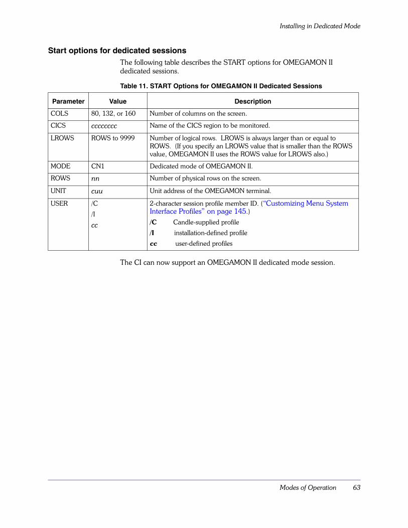
Modes of Operation 63
Installing in Dedicated Mode
Start options for dedicated sessionsThe following table describes the START options for OMEGAMON II dedicated sessions.
The CI can now support an OMEGAMON II dedicated mode session.
Table 11. START Options for OMEGAMON II Dedicated Sessions
Parameter Value Description
COLS 80, 132, or 160 Number of columns on the screen.
CICS cccccccc Name of the CICS region to be monitored.
LROWS ROWS to 9999 Number of logical rows. LROWS is always larger than or equal to ROWS. (If you specify an LROWS value that is smaller than the ROWS value, OMEGAMON II uses the ROWS value for LROWS also.)
MODE CN1 Dedicated mode of OMEGAMON II.
ROWS nn Number of physical rows on the screen.
UNIT cuu Unit address of the OMEGAMON terminal.
USER /C
/I
cc
2-character session profile member ID. (“Customizing Menu System Interface Profiles” on page 145.)
/C Candle-supplied profile
/I installation-defined profile
cc user-defined profiles

Installing in Dedicated Mode
64 OMEGAMON II for CICS Configuration and Customization Guide Version 520
Modifying the CICS Tables and JCL 65
Modifying the CICS Tables and JCL
Chapter OverviewTo use all the facilities of OMEGAMON II, you must install OMEGAMON II in the CICS address space. This chapter explains how to modify the CICS tables and JCL.
Chapter ContentsSystem Initialization Table (SIT) . . . . . . . . . . . . . . . . . . . . . . . . . . . . . . . . 66Program Load Table (PLT) . . . . . . . . . . . . . . . . . . . . . . . . . . . . . . . . . . . . 67Monitoring Control Table (MCT). . . . . . . . . . . . . . . . . . . . . . . . . . . . . . . . 68Defining the OMEGAMON II Program and Transaction . . . . . . . . . . . . . . 73Defining the Security for the OMEGAMON II Program . . . . . . . . . . . . . . . 75CICS JCL Changes. . . . . . . . . . . . . . . . . . . . . . . . . . . . . . . . . . . . . . . . . . 77
5
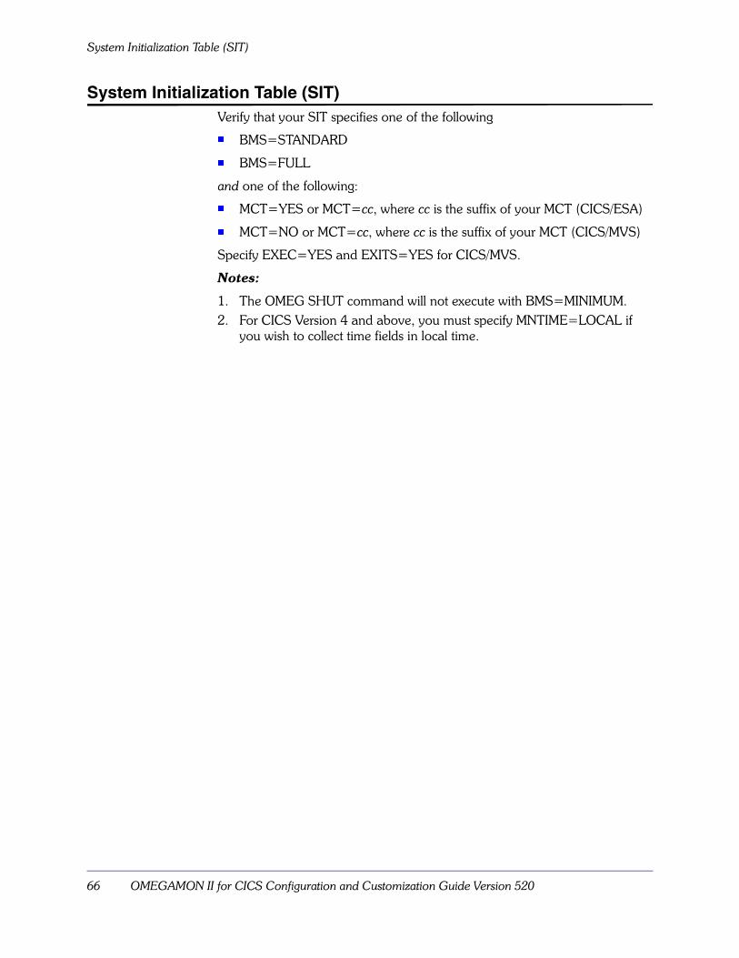
System Initialization Table (SIT)
66 OMEGAMON II for CICS Configuration and Customization Guide Version 520
System Initialization Table (SIT)Verify that your SIT specifies one of the following
� BMS=STANDARD
� BMS=FULL
and one of the following:
� MCT=YES or MCT=cc, where cc is the suffix of your MCT (CICS/ESA)
� MCT=NO or MCT=cc, where cc is the suffix of your MCT (CICS/MVS)
Specify EXEC=YES and EXITS=YES for CICS/MVS.
Notes:
1. The OMEG SHUT command will not execute with BMS=MINIMUM.2. For CICS Version 4 and above, you must specify MNTIME=LOCAL if
you wish to collect time fields in local time.

Modifying the CICS Tables and JCL 67
Program Load Table (PLT)
Program Load Table (PLT)The following shows the PLT additions for installation.
DFHPLT TYPE=ENTRY,PROGRAM=KOCOME00
Specify the PLT additions, as shown above, in the following tables:
� PLTPI (initialization) immediately after the DFHDELIM entry for CICS/ESA systems, or first in the PLTPI for CICS/MVS systems.
� PLTSD (shutdown) before the DFHDELIM entry.
There are, however, situations in which this is not the case. Some products, such as 3270 data stream compression utilities, modify data at CICS exit points. KOCOME00 should run after these products, in the PLT. This will ensure that OMEGAMON II can accurately report the modified data.

Monitoring Control Table (MCT)
68 OMEGAMON II for CICS Configuration and Customization Guide Version 520
Monitoring Control Table (MCT)For CICS/ESA, you must define user-event monitoring points in your MCT, if you want to collect
� Details about one or more of the following:
– Umbrella program names when you are using umbrella transaction services (see “Umbrella Transaction Services” on page 221)
– Certain fourth-generation language products (see“Installing Third-Party Support” on page 207)
– GMT offset time for each transaction (not necessary if you are only running CICS Version 4 and above)
– File and database I/O detail statistics
� DL/I usage per transaction
� DB2 usage per transaction
� MVS Workload Manager data
� Task history data
� Message queueing (MQ) file-level statistics
Candle provides the OMEGBSC segment, which you can define in the MCT to collect resource information. Use the OMEGBSC segment if you want to collect resource information, and you are not concerned about the additional overhead caused by collecting data your site does not need. To reduce the overhead caused by collecting unneeded data, see “Reducing data collection overhead” on page 71.
Note: The OMEGBSC segment is required to collect clock and counter statistics.
In CICS/MVS systems, OMEGAMON II collects monitoring data without using the CICS monitoring facility, so no changes to the MCT are required. For CICS Version 3 you must specify CPU=YES on the DFHMCT TYPE=INITIAL macro if you want OMEGAMON II to report on CPU usage per transaction.
Use the sample MCT entry shown in Figure 4 on page 70. You must be careful not to exclude fields that OMEGAMON II may need. If you are selectively including fields in your MCT, be sure the following monitoring points are included:
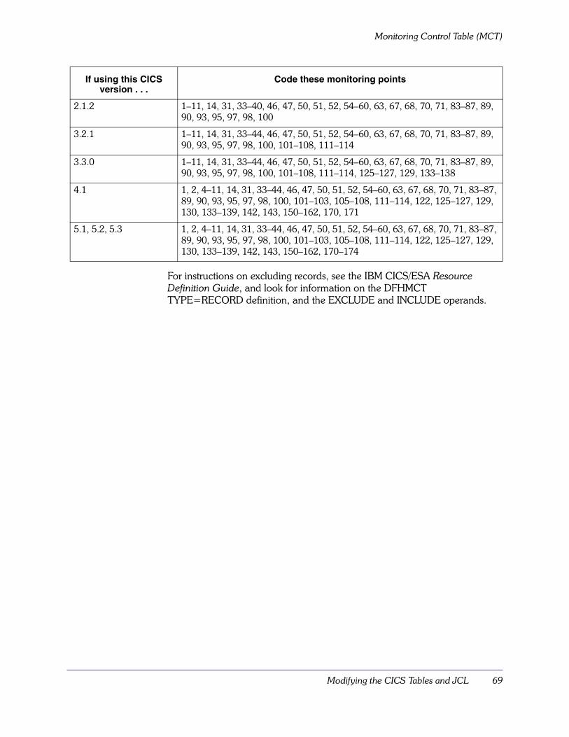
Modifying the CICS Tables and JCL 69
Monitoring Control Table (MCT)
For instructions on excluding records, see the IBM CICS/ESA Resource Definition Guide, and look for information on the DFHMCT TYPE=RECORD definition, and the EXCLUDE and INCLUDE operands.
If using this CICS version . . .
Code these monitoring points
2.1.2 1–11, 14, 31, 33–40, 46, 47, 50, 51, 52, 54–60, 63, 67, 68, 70, 71, 83–87, 89, 90, 93, 95, 97, 98, 100
3.2.1 1–11, 14, 31, 33–44, 46, 47, 50, 51, 52, 54–60, 63, 67, 68, 70, 71, 83–87, 89, 90, 93, 95, 97, 98, 100, 101–108, 111–114
3.3.0 1–11, 14, 31, 33–44, 46, 47, 50, 51, 52, 54–60, 63, 67, 68, 70, 71, 83–87, 89, 90, 93, 95, 97, 98, 100, 101–108, 111–114, 125–127, 129, 133–138
4.1 1, 2, 4–11, 14, 31, 33–44, 46, 47, 50, 51, 52, 54–60, 63, 67, 68, 70, 71, 83–87, 89, 90, 93, 95, 97, 98, 100, 101–103, 105–108, 111–114, 122, 125–127, 129, 130, 133–139, 142, 143, 150–162, 170, 171
5.1, 5.2, 5.3 1, 2, 4–11, 14, 31, 33–44, 46, 47, 50, 51, 52, 54–60, 63, 67, 68, 70, 71, 83–87, 89, 90, 93, 95, 97, 98, 100, 101–103, 105–108, 111–114, 122, 125–127, 129, 130, 133–139, 142, 143, 150–162, 170–174
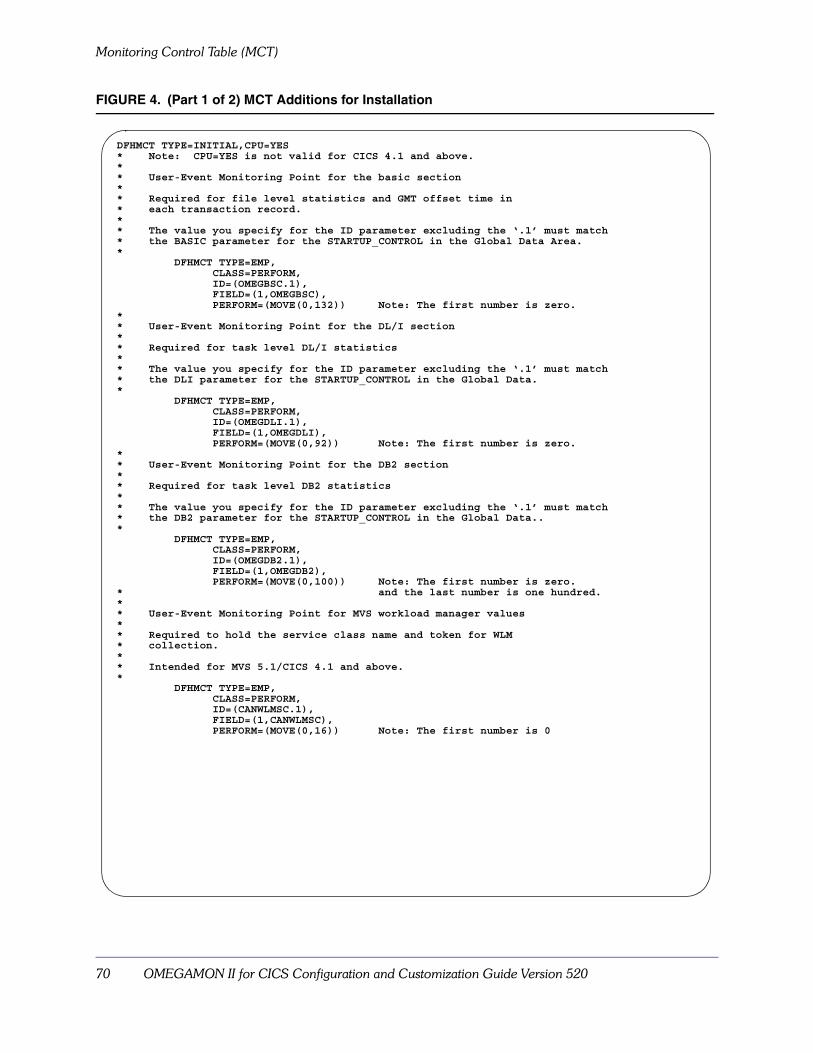
Monitoring Control Table (MCT)
70 OMEGAMON II for CICS Configuration and Customization Guide Version 520
FIGURE 4. (Part 1 of 2) MCT Additions for Installation
DFHMCT TYPE=INITIAL,CPU=YES* Note: CPU=YES is not valid for CICS 4.1 and above.** User-Event Monitoring Point for the basic section** Required for file level statistics and GMT offset time in* each transaction record.** The value you specify for the ID parameter excluding the ‘.1’ must match* the BASIC parameter for the STARTUP_CONTROL in the Global Data Area.*
DFHMCT TYPE=EMP,CLASS=PERFORM,ID=(OMEGBSC.1),FIELD=(1,OMEGBSC),PERFORM=(MOVE(0,132)) Note: The first number is zero.
** User-Event Monitoring Point for the DL/I section** Required for task level DL/I statistics** The value you specify for the ID parameter excluding the ‘.1’ must match* the DLI parameter for the STARTUP_CONTROL in the Global Data.*
DFHMCT TYPE=EMP,CLASS=PERFORM,ID=(OMEGDLI.1),FIELD=(1,OMEGDLI),PERFORM=(MOVE(0,92)) Note: The first number is zero.
** User-Event Monitoring Point for the DB2 section** Required for task level DB2 statistics** The value you specify for the ID parameter excluding the ‘.1’ must match* the DB2 parameter for the STARTUP_CONTROL in the Global Data..*
DFHMCT TYPE=EMP,CLASS=PERFORM,ID=(OMEGDB2.1),FIELD=(1,OMEGDB2),PERFORM=(MOVE(0,100)) Note: The first number is zero.
* and the last number is one hundred.** User-Event Monitoring Point for MVS workload manager values** Required to hold the service class name and token for WLM* collection.** Intended for MVS 5.1/CICS 4.1 and above.*
DFHMCT TYPE=EMP,CLASS=PERFORM,ID=(CANWLMSC.1),FIELD=(1,CANWLMSC),PERFORM=(MOVE(0,16)) Note: The first number is 0
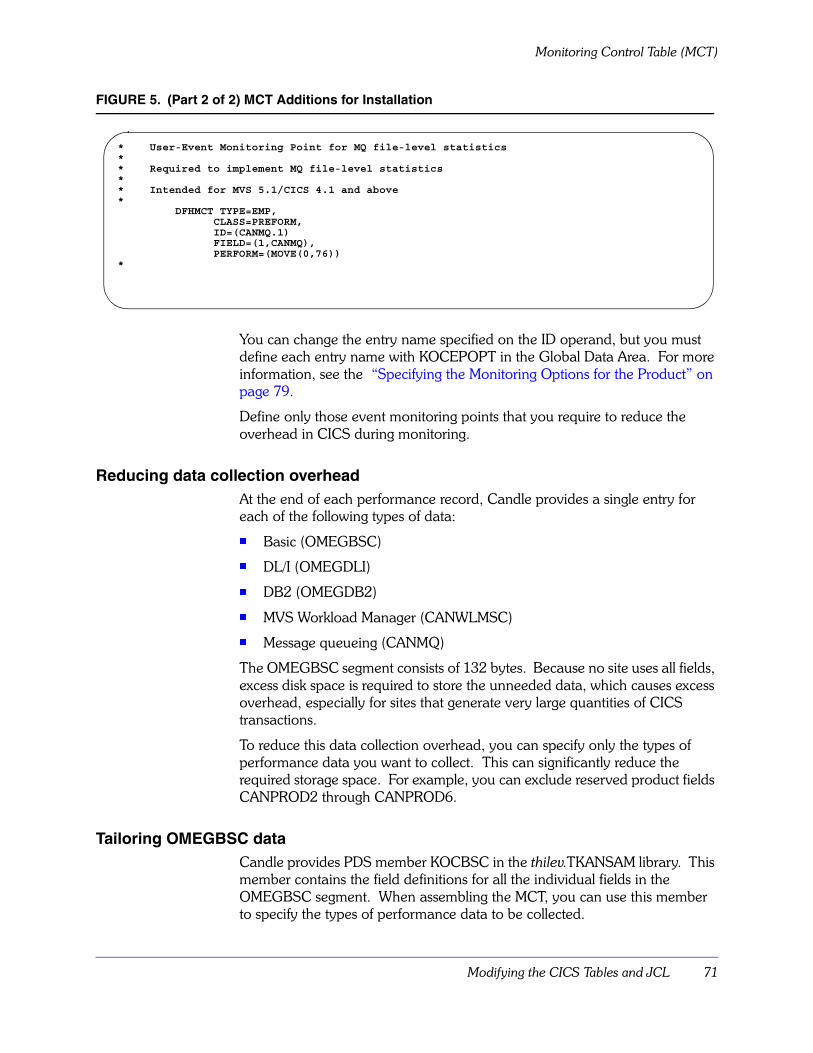
Modifying the CICS Tables and JCL 71
Monitoring Control Table (MCT)
FIGURE 5. (Part 2 of 2) MCT Additions for Installation
You can change the entry name specified on the ID operand, but you must define each entry name with KOCEPOPT in the Global Data Area. For more information, see the “Specifying the Monitoring Options for the Product” on page 79.
Define only those event monitoring points that you require to reduce the overhead in CICS during monitoring.
Reducing data collection overheadAt the end of each performance record, Candle provides a single entry for each of the following types of data:
� Basic (OMEGBSC)
� DL/I (OMEGDLI)
� DB2 (OMEGDB2)
� MVS Workload Manager (CANWLMSC)
� Message queueing (CANMQ)
The OMEGBSC segment consists of 132 bytes. Because no site uses all fields, excess disk space is required to store the unneeded data, which causes excess overhead, especially for sites that generate very large quantities of CICS transactions.
To reduce this data collection overhead, you can specify only the types of performance data you want to collect. This can significantly reduce the required storage space. For example, you can exclude reserved product fields CANPROD2 through CANPROD6.
Tailoring OMEGBSC dataCandle provides PDS member KOCBSC in the thilev.TKANSAM library. This member contains the field definitions for all the individual fields in the OMEGBSC segment. When assembling the MCT, you can use this member to specify the types of performance data to be collected.
* User-Event Monitoring Point for MQ file-level statistics** Required to implement MQ file-level statistics** Intended for MVS 5.1/CICS 4.1 and above*
DFHMCT TYPE=EMP,CLASS=PREFORM,ID=(CANMQ.1)FIELD=(1,CANMQ),PERFORM=(MOVE(0,76))
*
Monitoring Control Table (MCT)
72 OMEGAMON II for CICS Configuration and Customization Guide Version 520
To include all fields
To include all of the current fields, you can do either of the following in your MCT:
� Copy the unmodified PDS member KOCBSC.
� Use the OMEGBSC EMP
To include only selected fields
If you want to tailor your data collection, copy KOCBSC to your MCT and delete the unneeded fields.
Important usage notes� You should not define the OMEGBSC EMP in the MCT and choose some
of the individual fields. (If you do both, you will collect duplicate data.)
� If you use KOCBSC in your MCT, do not change the BASIC=OMEGBSC entry in KOCEPOPT.
� Some fields are required by the task history or reporter function of OMEGAMON II for CICS. If you code only the fields required for your site, some data required by OMEGAMON II task history or reporter functions may be missing. Member KOCBSC contains information about each field and how it is used within the OMEGAMON II system.
� If you do not use the entire OMEGBSC segment, and if you use non-Candle programs (for example, SAS) to read and report on SMF records, these non-Candle programs may require modification.
Modifying the CICS Tables and JCL 73
Defining the OMEGAMON II Program and Transaction
Defining the OMEGAMON II Program and TransactionThis section contains information about using the CICS-supplied CEDA transaction to define the program and transaction. The program and transaction manage the interface between OMEGAMON II and CICS.
OMEGAMON II programFollow these steps in customizing the CEDA definition for the OMEGAMON II program:
1. Specify KOCOME00 as the program name.
2. Specify Assembler as the language.
3. If you have CICS/ESA, do the following:� Specify CMDSEC=NO and RESSEC=NO= on the CEDA definition for
the OMEG transaction.
� In addition, if XPPT=YES in your SIT, you must also define KOCOME00 as a resource to your external security manager.
� In addition, if you have CICS/ESA version 3.3 or higher and if STGPROT=YES in your SIT, you must also specify EXECKEY(CICS) on the CEDA definition for the program KOCOME00.
4. All other values should be allowed to default.

Defining the OMEGAMON II Program and Transaction
74 OMEGAMON II for CICS Configuration and Customization Guide Version 520
OMEGAMON II transactionFollow these steps in customizing the CEDA definition for the OMEGAMON II transaction:
1. For the transaction ID, specify OMEG or another 1–4-character ID.
2. Specify TCLASS(NO).
3. In addition, if you have CICS/ESA version 3.3 or higher and if STGPROT=YES in your SIT, you must also specify TASKDATAKEY(CICS) on the CEDA definition for the OMEG transaction.
4. Specify SPURGE(NO) and DTIMOUT(NO) to prevent AEXY abends.
5. All other values should be allowed to default.Notes:
1. Candle suggests that you use OMEG as the OMEGAMON II transaction ID to help make problem determination/diagnosis and maintenance simpler. You can, however, choose a different ID if necessary for business or administrative reasons. If you use another transaction ID, substitute that ID wherever the OMEG transaction is mentioned in this manual.
2. If you do not define TCLASS as NO, the transaction may not run, and many OMEGAMON II functions will be unavailable.
3. To avoid confusion, Candle recommends that only one transaction ID invokes program KOCOME00.
If initialization failsOMEGAMON II initialization within CICS will terminate and message OC1029 will be issued if a valid transaction ID associated with program KOCOME00 cannot be found. If this is the case, you have either
� failed to define the OMEGAMON II transaction or
� defined the transaction incorrectly
Review the instructions in this section, and try again to define the transaction.

Modifying the CICS Tables and JCL 75
Defining the Security for the OMEGAMON II Program
Defining the Security for the OMEGAMON II Program This section contains information about specifying the security for the OMEGAMON II program.
Specifying security for the OMEGAMON II program CICS provides more that one method to protect against unauthorized access.
Candle recommends that you specify CMDSEC=NO and RESSEC=NO in both of these cases.
� The installation is an existing installation.
� The installation is a new installation. (Once you have started OMEGAMON II, you can change the values to the standard at your site.)
If you do not specify CMDSEC=NO and RESSEC=NO, you must
� define the resources used by OMEGAMON II to the external security program
� provide access to these resources for the appropriate users

Defining the Security for the OMEGAMON II Program
76 OMEGAMON II for CICS Configuration and Customization Guide Version 520
Defining the resources used by OMEGAMON II to the external security program You must define the following resources used by OMEGAMON II to the external security program.
Table 12. Resources Used by OMEGAMON II
Users who will require access to the resource The resources listed in the table need to be accessed by the following users.
� users executing the OMEG transaction
� if KOCOME00 is in the startup PLT and PLTPISEC=ALL/RESSEC/CMDSEC and a PLTIUSR is not specified, the CICS region user ID
� if KOCOME00 is in the startup PLT and PLTPISEC=ALL/RESSEC/CMDSEC, the PLTPIUSR user ID
� if KOCOME00 in the shutdown PLT, the users executing CEMT P SHUT
Customizing security for commands and the CUA interfaceFor information about customizing security for commands and the CUA interface, see the chapters “Function Level Security” on page 137 and “Customizing CUA Interface Security” on page 127.
Type of Resource
Name of the Resource
Condition Requiring Access
Access Required
Additional Information (If Any)
ACICSPCT OMEG XPCT=YES and RESSEC=YES
READ
CCICSCMD EXITPROGRAM XCMD=YES and CMDSEC=YES
UPDATE A regular shutdown of CICS may not be possible. If missing. an abend SA03 can occur and the shutdown will require CEMT P SHUT IMMED.
MONITOR XCMD=YES and CMDSEC=YES
UPDATE A regular shutdown of CICS may not be possible. If missing. an abend SA03 can occur and the shutdown will require CEMT P SHUT IMMED.
PROGRAM XCMD=YES and CMDSEC=YES
READ If omitted OMEG REMOVE will not work correctly and program KOCOME00 will not be removed from storage.
TRANSACTION XCMD=YES and CMDSEC=YES
READ
MCICSPPT KOCOME00 XPPT=YES and RESSEC=YES
READ
DCICSDCT CSSL XDCT=YES and RESSEC=YES
UPDATE This is optional. If omitted, no messages will be written to CSSL.
TCICSTRN OMEG XTRAN=YES READ

Modifying the CICS Tables and JCL 77
CICS JCL Changes
CICS JCL ChangesAdd a DD statement for RKANMOD and concatenate the OMEGAMON II load library, RKANMOD, to DFHRPL:
//RKANMOD DD DISP=SHR,DSN=rhilev.RKANMOD
//DFHRPL DD DISP=SHR,DSN=......
// DD DISP=SHR,DSN=rhilev.RKANMOD
Notes:
1. If you define an RTE that uses the SMP libraries, you must concatenate the TKANMOD load library as follows://RKANMOD DD DISP=SHR,DSN=thilev.TKANMOD
//DFHRPL DD DISP=SHR,DSN=......
// DD DISP=SHR,DSN=thilev.TKANMOD
2. Program KOCOME00 is the only program loaded from the DFHRPL concatenation. You can copy this program to a separate DFHRPL to reduce PDS directory search times.
You must also add a DD statement to specify the global module that you want to use if other than a non-suffixed default. See “Specifying the Monitoring Options for the Product” on page 79 for information on creating the Global Data Area and the JCL changes required.
To run multiple common interfaces, see “Installing Multiple Collector Address Spaces” on page 237.
If you include program KOCOME00 in your PLTPI, you can ensure that the OMEGAMON II address space is active before your CICS region completes initialization. To exercise this option, add the following DD statement to the CICS startup JCL:
//OCCIREQ DD DUMMY
After you add the DD statement, program KOCOME00 checks that the cross-memory interface task (XMIT) is running as a subtask of the menu system. If the subtask is active, initialization continues. If the subtask is not active, the following WTOR message appears:
OC0806: XMCR OCCIREQ SPECIFIED IN STARTUP JCL BUT RKC2XMcc
NOT ACTIVE. REPLY ABEND, IGNORE OR RETRY.
In the message, cc is replaced by the suffix specified in the //RKC2XMcc DD statement in the CICS startup JCL or, if no suffix was specified, by the default (00).
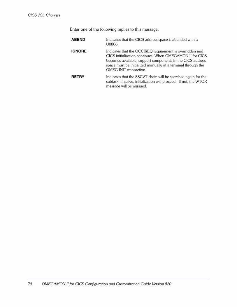
CICS JCL Changes
78 OMEGAMON II for CICS Configuration and Customization Guide Version 520
Enter one of the following replies to this message:
ABEND Indicates that the CICS address space is abended with a U0806.
IGNORE Indicates that the OCCIREQ requirement is overridden and CICS initialization continues. When OMEGAMON II for CICS becomes available, support components in the CICS address space must be initialized manually at a terminal through the OMEG INIT transaction.
RETRY Indicates that the SSCVT chain will be searched again for the subtask. If active, initialization will proceed. If not, the WTOR message will be reissued.
Specifying the Monitoring Options for the Product 79
Specifying the Monitoring Optionsfor the Product
Chapter OverviewThis chapter contains information about specifying monitoring options for OMEGAMON II for CICS.
This chapter also covers the changes made to the configuration process between V500 and V520.
Chapter ContentsBackground about the Monitoring Options . . . . . . . . . . . . . . . . . . . . . . . . 80Displaying and Printing Information about the Monitoring Options. . . . . . 81Determining What to Do Next . . . . . . . . . . . . . . . . . . . . . . . . . . . . . . . . . 82Migrating the Monitoring Options for the Product . . . . . . . . . . . . . . . . . . . 83Specifying the Values for the Monitoring Options in the Product . . . . . . . . 88Refreshing the Monitoring Options . . . . . . . . . . . . . . . . . . . . . . . . . . . . . . 96Additional Considerations. . . . . . . . . . . . . . . . . . . . . . . . . . . . . . . . . . . . . 97
6

Background about the Monitoring Options
80 OMEGAMON II for CICS Configuration and Customization Guide Version 520
Background about the Monitoring Options
Background about the Global Data AreaThe Global Data Area sets the values for the monitoring options for OMEGAMON II. These values are generated during configuration and apply to all OMEGAMON II sessions that are monitoring the same CICS region. The Global Data Area is configured through the Candle Installation and Configuration Assistance Tool (CICAT).
The Global Data Area enables you to set options for OMEGAMON II features, such as:
� the task history collector
� the historical reporter
� the interval record collector
� the response time collector i
Background about the changes to the Global Data Area between V500 and V520 When you configured OMEGAMON II for CICS V500 and below, you specified the values for the monitoring options using the Global Data Area module. For example, you used the KOCGLB macro in the Global Data Area module to specify the components of the product that are started automatically.
In OMEGAMON II for CICS V520, you specify the values for the monitoring options using the parameters in the Global Data Area.
Background about the monitoring options and the Global Data Area in V520For OMEGAMON II for CICS V520, CICAT provides a set of defaults for the Global Data Area in the member KC2GLB. This member becomes the default for the Global Data Area in the CICS region JCL.
When you configure OMEGAMON II for CICS using CICAT, you can select to update the monitoring options using the parameters in the Global Data Area.
Return codesYou must receive a return code of 0 during the APPLY step. If not, you must correct any assembly errors and resubmit the job until you receive a 0 return code.
Important
Do not RECEIVE and APPLY preventative maintenance before you have resolved all non-zero return codes.
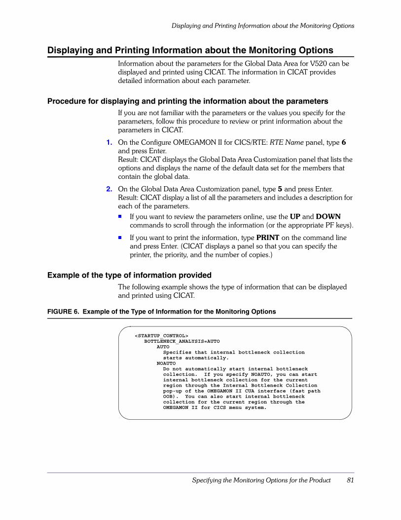
Specifying the Monitoring Options for the Product 81
Displaying and Printing Information about the Monitoring Options
Displaying and Printing Information about the Monitoring Options Information about the parameters for the Global Data Area for V520 can be displayed and printed using CICAT. The information in CICAT provides detailed information about each parameter.
Procedure for displaying and printing the information about the parametersIf you are not familiar with the parameters or the values you specify for the parameters, follow this procedure to review or print information about the parameters in CICAT.
1. On the Configure OMEGAMON II for CICS/RTE: RTE Name panel, type 6 and press Enter. Result: CICAT displays the Global Data Area Customization panel that lists the options and displays the name of the default data set for the members that contain the global data.
2. On the Global Data Area Customization panel, type 5 and press Enter.Result: CICAT display a list of all the parameters and includes a description for each of the parameters. � If you want to review the parameters online, use the UP and DOWN
commands to scroll through the information (or the appropriate PF keys).
� If you want to print the information, type PRINT on the command line and press Enter. (CICAT displays a panel so that you can specify the printer, the priority, and the number of copies.)
Example of the type of information provided The following example shows the type of information that can be displayed and printed using CICAT.
FIGURE 6. Example of the Type of Information for the Monitoring Options
<STARTUP_CONTROL>BOTTLENECK_ANALYSIS=AUTO
AUTOSpecifies that internal bottleneck collectionstarts automatically.
NOAUTODo not automatically start internal bottleneckcollection. If you specify NOAUTO, you can startinternal bottleneck collection for the currentregion through the Internal Bottleneck Collectionpop-up of the OMEGAMON II CUA interface (fast pathOOB). You can also start internal bottleneckcollection for the current region through theOMEGAMON II for CICS menu system.

Determining What to Do Next
82 OMEGAMON II for CICS Configuration and Customization Guide Version 520
Determining What to Do Next
Prerequisites for using the Global Data AreaBefore you being to work with the Global Data Area, be sure you have reviewed:
� “Background about the Monitoring Options” on page 80
� “Specifying the Values for the Monitoring Options in the Product” on page 88
Determining what to do next� If you have used OMEGAMON II for CICS in the past and you are
familiar with the Global Data Area module and the macros the module contains, see the topic “Migrating the Monitoring Options for the Product” on page 83.
� If you have not used OMEGAMON II for CICS in the past, see the topic “Specifying the Values for the Monitoring Options in the Product” on page 88.

Specifying the Monitoring Options for the Product 83
Migrating the Monitoring Options for the Product
Migrating the Monitoring Options for the Product
Limitations on using the Global Data Area in V500 and below You cannot convert the Global Data Area in OMEGAMON II for CICS V500 or below using CICAT batch mode. You can use
� CICAT interactive mode to convert the Global Data Area to the format being used by OMEGAMON II for CICS V520
� CICAT batch mode to replicate the runtime environments (RTEs) that contain the converted Global Data Area in OMEGAMON II V520
Converting the Global Data Area Follow this procedure using CICAT to convert the Global Data Area from OMEGAMON II for CICS V500 or below to the format being used by OMEGAMON II for CICS V520.
1. On the Configure OMEGAMON II for CICS/RTE: RTE Name panel, type 6 and press Enter. Result: CICAT displays the Global Data Area Customization panel.
2. On the Global Data Area Customization panel, type 4 and press Enter. Result: CICAT displays the Global Data Area Conversion panel.
3. Specify the name of the data set that contains the modules from the prior version of OMEGAMON II and press Enter. (The default is rhilev.midlev.INSTDATA. You can also repeat this step if you store the modules in more than one data set.)Result: CICAT displays a list of the modules in the data set you specified.
4. Type S in the select field for the modules you want to convert and press F3. Result: CICAT displays the JCL for converting the modules.
5. Review the JCL.
6. On the command line, type SUBMIT and press Enter.
7. Exit CICAT. Result: CICAT converts the Global Data Area and copies the members that contain the parameters for the Global Data Area to the data set you specified. (The new members have the same names as the existing modules.)
Migrating the Monitoring Options for the Product
84 OMEGAMON II for CICS Configuration and Customization Guide Version 520
Installing the converted Global Data Area Once you have converted the Global Data Area using CICAT, you must also install the new Global Data Area in the RTE. Follow this procedure to install the Global Data Area using CICAT.
1. On the Configure OMEGAMON II for CICS/RTE: RTE Name panel, type 6 and press Enter. Result: CICAT displays the Global Data Area Customization panel that lists the options and displays the name of the default data set for the members that contain the new parameters.
2. On the Global Data Area Customization panel, type 3 and press Enter. Result: CICAT � creates a list of the suffixes of the Global Data Areas installed for the RTE
(If you replicate the RTE using batch mode, CICAT also installs the Global Data Areas for the RTE when it is replicated.)
� copies the new members to rhilev.midlev.RKANPAR and displays the JCL for installing the Global Data Areas
3. Review the JCL.
4. On the command line, type SUBMIT and press Enter.
5. Exit CICAT. Result: CICAT installs the Global Data Areas. The next time you access CICAT, CICAT redisplays the Configure OMEGAMON II for CICS/RTE: RTE Name panel (if the job is complete).
6. Once you have completed all the steps for the configuration, be sure to follow the instructions displayed when you select Complete the configuration (option 4) on the OMEGAMON II for CICS/RTE: RTE Name panel. These instructions contain information about specifying the Global Data Area in the CICS region JCL.

Specifying the Monitoring Options for the Product 85
Migrating the Monitoring Options for the Product
Relationship of the Global Data Area in V500 to the Global Data Area in V520 The following table shows the relationship of the keywords and macros in the Global Data Area module for OMEGAMON II for CICS V500 or below to the new parameters in the Global Data Area (KC2GLB) for OMEGAMON II for CICS in V520.
Table 13. Relationship of the Global Data Area in V500 to V520
Macro in V500
New Location in V520
Keyword in Macro in V500
New Parameter in V520
KOCBLST BOTTLENECK_ANALYSIS DISPLAY and ID cccc=YES
KOCCPU CPU_EXCLUDED_TRANS XTRAN CPU_EXCLUDED_TRANS
KOCDBCOL DATABASE_COLLECTION AUTO AUTO_START
NAME DATABASE_COLLECTION
ONDV ONDV_WRITE
SMF SMF_WRITE
KOCDEX BOTTLENECK_OPTIONS CLRL CLEAR_INTERVAL_LONG
CLRS CLEAR_INTERVAL_SHORT
STIM SAMPLE_INTERVAL
VBS VARIABLE_BUCKETS
XTRAN EXCLUDED_TRANS
KOCGLB EXCEPTION_ANALYSIS_INTERVALS
STGVINT VIOLAITONS_MONITORING_INTERVAL
VSAMINT VSAM_MONITORING_INTERVAL
GLOBAL_OPTIONS CONVTIME CONVERSE_TIME
DB2 DB2_SECTION
DEX BOTTLENECK_ANALYSIS
DLI DLI_CLOCKS_AND_COUNTERS
DUMPINT DUMPS_MONITORING_INTERVAL
FREQ ETE_FREQUENCY
INTERVAL ETE_INTERVAL
MAXGRPS MAX_GROUPS
MAXIDS MAX_IDS
SHUTOPT SHUT_OPTIONS
SMFID SMFID
UETRACE USER_EXIT_TRACE
XMRCDS XM_BUFFER_RECORDS

Migrating the Monitoring Options for the Product
86 OMEGAMON II for CICS Configuration and Customization Guide Version 520
Existing Macro
New Location in KC2GLB
Keyword in Existing Macro
Name of New Parameter in KC2GLB
KOCGLB STARTUP_CONTROL INTR INTERVAL_RECORDING
MAXR CPU_THRESHOLDING
ONDV ONLINE_DATA_VIEWING
RTA RESPONSE_TIME_ANALYSIS
RESOURCE_LIMITING RLIM RESOURCE_LIMITING
N/A PRINT N/A (The keyword has been removed for V520.)
KOCGROUP GROUP_DEFINITIONS ELOG RESPONSE_TIME_THRESHOLD
GRP GROUP_NUMBER
GTYP GROUP_TYPE
NAME GROUP_NAME
KOCEPOPT USER_EVENT_MONITRING BASIC BASIC_SECTION
DB2 DB2_SECTION
DLI DLI_SECTION
EXITSOFF EXIT_SUPPRESSION
MONITOR CICS_CMF_MONITORING
MQ MQ_SECTION
SMFCICS and SMFCICS3
CICSESA_SMF_RECORDS
XTRAN EXCLUDED_TRANS
KOCEXEC CPU_MONITORING MAXCPU CPU_THRESHOLD
KOCID ID ETEHOST HOST_RESPONSE_THRESHOLD
ETENET NETWORK_RESPONSE_THRESHOLD
GROUPS ELIGIBLE_GROUPS
ID ID
LU LU
PROG PROG
TASKREQ TASKREQ
TERM TERM
THRESH TOTAL_RESPONSE_THRESHOLD
TRAN TRAN
GROUP_ELEMENTS SCALE GRAPH_SCALE
WINDOWN TIME_WINDOW
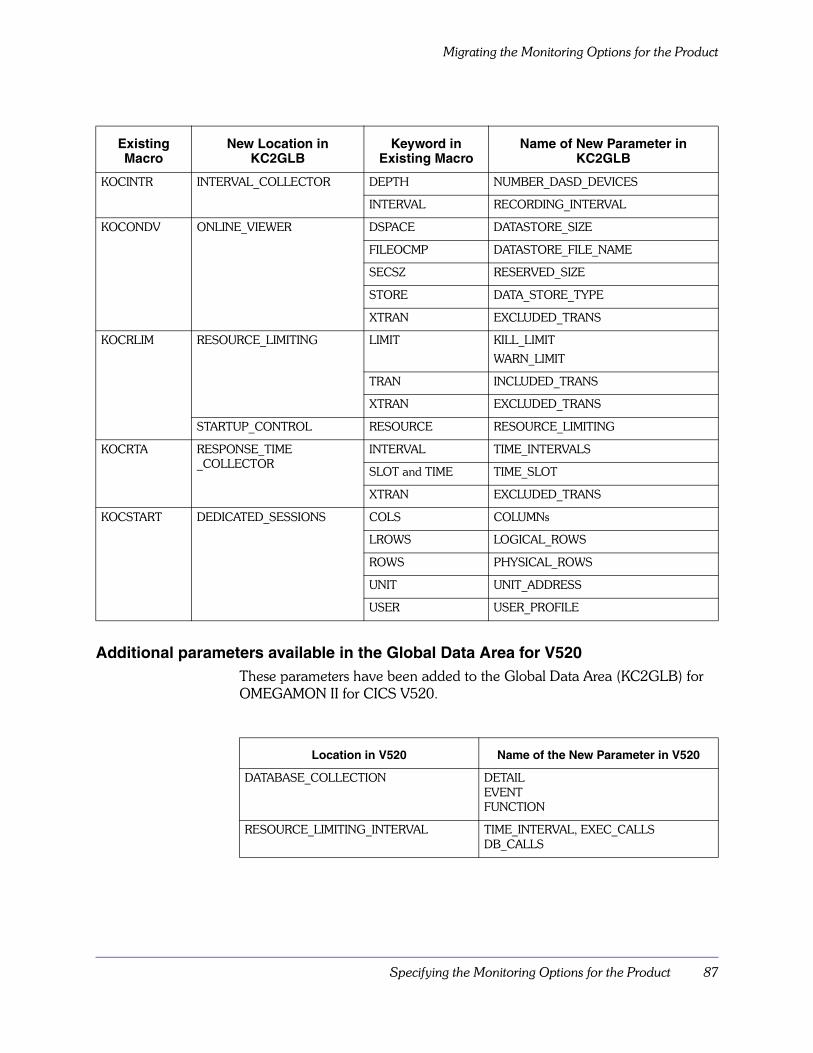
Specifying the Monitoring Options for the Product 87
Migrating the Monitoring Options for the Product
Additional parameters available in the Global Data Area for V520These parameters have been added to the Global Data Area (KC2GLB) for OMEGAMON II for CICS V520.
Existing Macro
New Location in KC2GLB
Keyword in Existing Macro
Name of New Parameter in KC2GLB
KOCINTR INTERVAL_COLLECTOR DEPTH NUMBER_DASD_DEVICES
INTERVAL RECORDING_INTERVAL
KOCONDV ONLINE_VIEWER DSPACE DATASTORE_SIZE
FILEOCMP DATASTORE_FILE_NAME
SECSZ RESERVED_SIZE
STORE DATA_STORE_TYPE
XTRAN EXCLUDED_TRANS
KOCRLIM RESOURCE_LIMITING LIMIT KILL_LIMIT
WARN_LIMIT
TRAN INCLUDED_TRANS
XTRAN EXCLUDED_TRANS
STARTUP_CONTROL RESOURCE RESOURCE_LIMITING
KOCRTA RESPONSE_TIME_COLLECTOR
INTERVAL TIME_INTERVALS
SLOT and TIME TIME_SLOT
XTRAN EXCLUDED_TRANS
KOCSTART DEDICATED_SESSIONS COLS COLUMNs
LROWS LOGICAL_ROWS
ROWS PHYSICAL_ROWS
UNIT UNIT_ADDRESS
USER USER_PROFILE
Location in V520 Name of the New Parameter in V520
DATABASE_COLLECTION DETAILEVENTFUNCTION
RESOURCE_LIMITING_INTERVAL TIME_INTERVAL, EXEC_CALLSDB_CALLS
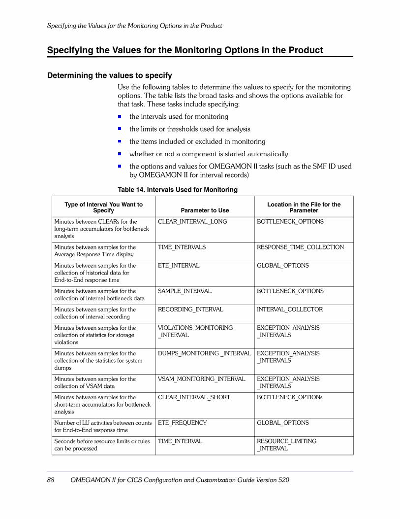
Specifying the Values for the Monitoring Options in the Product
88 OMEGAMON II for CICS Configuration and Customization Guide Version 520
Specifying the Values for the Monitoring Options in the Product
Determining the values to specify Use the following tables to determine the values to specify for the monitoring options. The table lists the broad tasks and shows the options available for that task. These tasks include specifying:
� the intervals used for monitoring
� the limits or thresholds used for analysis
� the items included or excluded in monitoring
� whether or not a component is started automatically
� the options and values for OMEGAMON II tasks (such as the SMF ID used by OMEGAMON II for interval records)
Table 14. Intervals Used for Monitoring
Type of Interval You Want to Specify Parameter to Use
Location in the File for the Parameter
Minutes between CLEARs for the long-term accumulators for bottleneck analysis
CLEAR_INTERVAL_LONG BOTTLENECK_OPTIONS
Minutes between samples for the Average Response Time display
TIME_INTERVALS RESPONSE_TIME_COLLECTION
Minutes between samples for the collection of historical data for End-to-End response time
ETE_INTERVAL GLOBAL_OPTIONS
Minutes between samples for the collection of internal bottleneck data
SAMPLE_INTERVAL BOTTLENECK_OPTIONS
Minutes between samples for the collection of interval recording
RECORDING_INTERVAL INTERVAL_COLLECTOR
Minutes between samples for the collection of statistics for storage violations
VIOLATIONS_MONITORING_INTERVAL
EXCEPTION_ANALYSIS_INTERVALS
Minutes between samples for the collection of the statistics for system dumps
DUMPS_MONITORING _INTERVAL EXCEPTION_ANALYSIS_INTERVALS
Minutes between samples for the collection of VSAM data
VSAM_MONITORING_INTERVAL EXCEPTION_ANALYSIS_INTERVALS
Minutes between samples for the short-term accumulators for bottleneck analysis
CLEAR_INTERVAL_SHORT BOTTLENECK_OPTIONs
Number of LU activities between counts for End-to-End response time
ETE_FREQUENCY GLOBAL_OPTIONS
Seconds before resource limits or rules can be processed
TIME_INTERVAL RESOURCE_LIMITING_INTERVAL
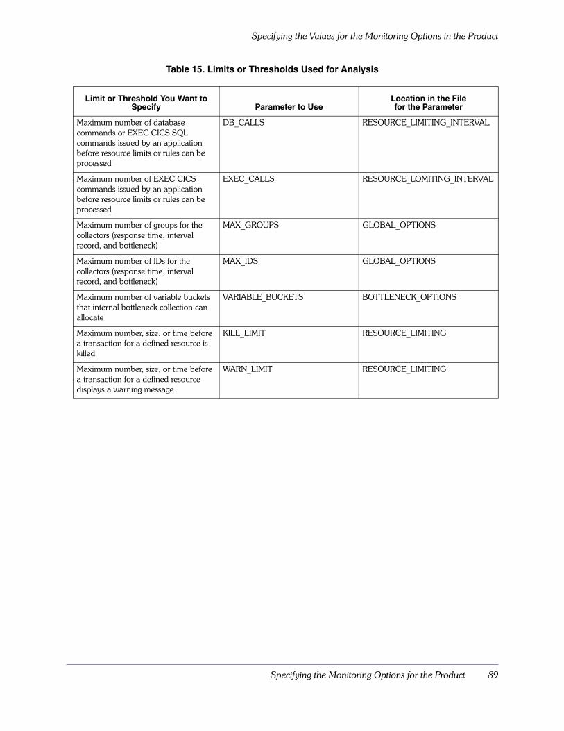
Specifying the Monitoring Options for the Product 89
Specifying the Values for the Monitoring Options in the Product
Table 15. Limits or Thresholds Used for Analysis
Limit or Threshold You Want to Specify Parameter to Use
Location in the File for the Parameter
Maximum number of database commands or EXEC CICS SQL commands issued by an application before resource limits or rules can be processed
DB_CALLS RESOURCE_LIMITING_INTERVAL
Maximum number of EXEC CICS commands issued by an application before resource limits or rules can be processed
EXEC_CALLS RESOURCE_LOMITING_INTERVAL
Maximum number of groups for the collectors (response time, interval record, and bottleneck)
MAX_GROUPS GLOBAL_OPTIONS
Maximum number of IDs for the collectors (response time, interval record, and bottleneck)
MAX_IDS GLOBAL_OPTIONS
Maximum number of variable buckets that internal bottleneck collection can allocate
VARIABLE_BUCKETS BOTTLENECK_OPTIONS
Maximum number, size, or time before a transaction for a defined resource is killed
KILL_LIMIT RESOURCE_LIMITING
Maximum number, size, or time before a transaction for a defined resource displays a warning message
WARN_LIMIT RESOURCE_LIMITING

Specifying the Values for the Monitoring Options in the Product
90 OMEGAMON II for CICS Configuration and Customization Guide Version 520
Table 16. Items Included or Excluded in Monitoring
Object or Value You Want to Include or Exclude in Monitoring
Parameter to Use Location in the File for the Parameter
CPU for specific tasks or transactions EXCLUDED_TRANS CPU_EXCLUDED_TRANSACTIONS
Group elements GRAPH_SCALETIME_WINDOW
GROUP_ELEMENTS
Group elements IDs group ID (such as TRAN or PROG) ID
Groups (transaction, terminal and program groups for bottelneck collection as wells as VTAM LU groups for response time monitoring)
GROUP GROUP_DEFINITIONS
Specific long-running CICS tasks from CPU threshold settings
EXCLUDED_TRANS CPU_EXCLUDED_TRANS
Statistics for the task history collector for databases
ONDV_WRITE DATABASE_COLLECTION
Terminal I/O and IRC wait time in the calculation for total response time for conversational transactions
CONVERSE_TIME GLOBAL OPTIONS
Transactions for defined resources INCLUDE_TRANSEXCLUDE_TRANS
RESOURCE_LIMITING
Transaction for response time analysis EXCLUDED_TRANS RESPONSE_TIME_COLLECTION
Transactions for SMF logging EXCLUDED_TRANS USER_EVENT_MONITORING
Transactions for the task history collector
EXCLUDED_TRANS ONLINE_VIEWER
Type of database databasetype (for example, ADABAS) DATABASE_COLLECTION
Type of resource VSAMDSAEDSACPUELAPSEDDLIADABASIDMSDATACOMSUPRADB2MQUSEREVNT1
RESOURCE_LIMITING
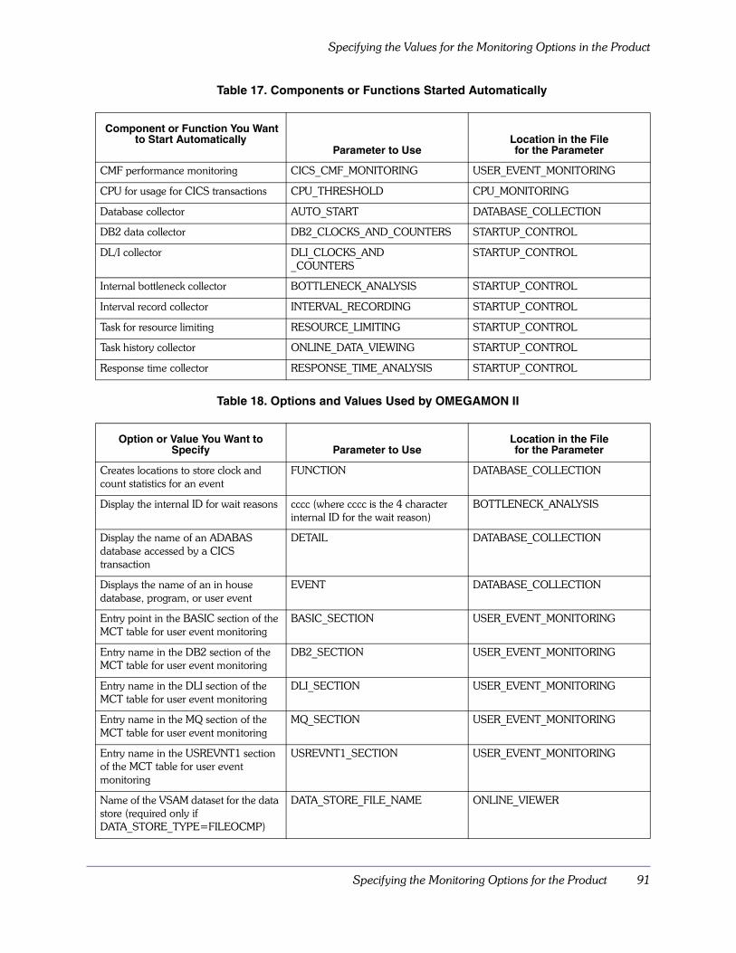
Specifying the Monitoring Options for the Product 91
Specifying the Values for the Monitoring Options in the Product
Table 17. Components or Functions Started Automatically
Table 18. Options and Values Used by OMEGAMON II
Component or Function You Want to Start Automatically
Parameter to Use Location in the File for the Parameter
CMF performance monitoring CICS_CMF_MONITORING USER_EVENT_MONITORING
CPU for usage for CICS transactions CPU_THRESHOLD CPU_MONITORING
Database collector AUTO_START DATABASE_COLLECTION
DB2 data collector DB2_CLOCKS_AND_COUNTERS STARTUP_CONTROL
DL/I collector DLI_CLOCKS_AND_COUNTERS
STARTUP_CONTROL
Internal bottleneck collector BOTTLENECK_ANALYSIS STARTUP_CONTROL
Interval record collector INTERVAL_RECORDING STARTUP_CONTROL
Task for resource limiting RESOURCE_LIMITING STARTUP_CONTROL
Task history collector ONLINE_DATA_VIEWING STARTUP_CONTROL
Response time collector RESPONSE_TIME_ANALYSIS STARTUP_CONTROL
Option or Value You Want to Specify Parameter to Use
Location in the File for the Parameter
Creates locations to store clock and count statistics for an event
FUNCTION DATABASE_COLLECTION
Display the internal ID for wait reasons cccc (where cccc is the 4 character internal ID for the wait reason)
BOTTLENECK_ANALYSIS
Display the name of an ADABAS database accessed by a CICS transaction
DETAIL DATABASE_COLLECTION
Displays the name of an in house database, program, or user event
EVENT DATABASE_COLLECTION
Entry point in the BASIC section of the MCT table for user event monitoring
BASIC_SECTION USER_EVENT_MONITORING
Entry name in the DB2 section of the MCT table for user event monitoring
DB2_SECTION USER_EVENT_MONITORING
Entry name in the DLI section of the MCT table for user event monitoring
DLI_SECTION USER_EVENT_MONITORING
Entry name in the MQ section of the MCT table for user event monitoring
MQ_SECTION USER_EVENT_MONITORING
Entry name in the USREVNT1 section of the MCT table for user event monitoring
USREVNT1_SECTION USER_EVENT_MONITORING
Name of the VSAM dataset for the data store (required only if DATA_STORE_TYPE=FILEOCMP)
DATA_STORE_FILE_NAME ONLINE_VIEWER

Specifying the Values for the Monitoring Options in the Product
92 OMEGAMON II for CICS Configuration and Customization Guide Version 520
Number of DASD devices allocated to the CICS region
NUMBER_DASD_DEVICES INTERVAL_COLLECTOR
Number of records in the buffer for transaction records before they are sent to the collectors (response time and history)
XM_BUFFERS_RECORDS GLOBAL_OPTIONS
Percentage of the dataspace used for file, database clock and counter statistics and application trace records (required only if DATA_STORE_TYPE=DSPACE)
RESERVED_SIZE ONLINE_VIEWER
Size of the dataspace for the data store (required only if DATA_STORE_TYPE=DSPACE)
DATA_STORE_SIZE ONLINE_VIEWER
SMF ID used for interval records SMFID GLOBAL_OPTIONS
Start time and end time for the Today’s Response Time display
TIME_SLOT RESPONSE_TIME_COLLECTION
Suppress specified global user exits for user event monitoring
EXIT_SUPPRESSION USER_EVENT_MONTITORING
Terminal values for dedicated mode sessions
UNIT DEDICATED_SESSIONS
Type of data store used for the data collected for task history
DATA_STORE_TYPE ONLINE_VIEWER
Whether or not to alter for user exit tracing
USER_EXIT_TRACE GLOBAL_OPTIONS
Whether or not to purge conversational tasks waiting on terminal I/O when CICS is shutdown
SHUT_OPTIONS GLOBAL_OPTIONS
Whether or not the MAXR exception is tripped when CPU consumption exceeds MAXCPU
CPU_THRESHOLDING STARTUP_CONTROL
Write database collection statistics to SMF
SMF_WRITE DATABASE_COLLECTION
Write SMF 110 records CICSESA_SMF_RECORDS USER_EVENT_MONITORING
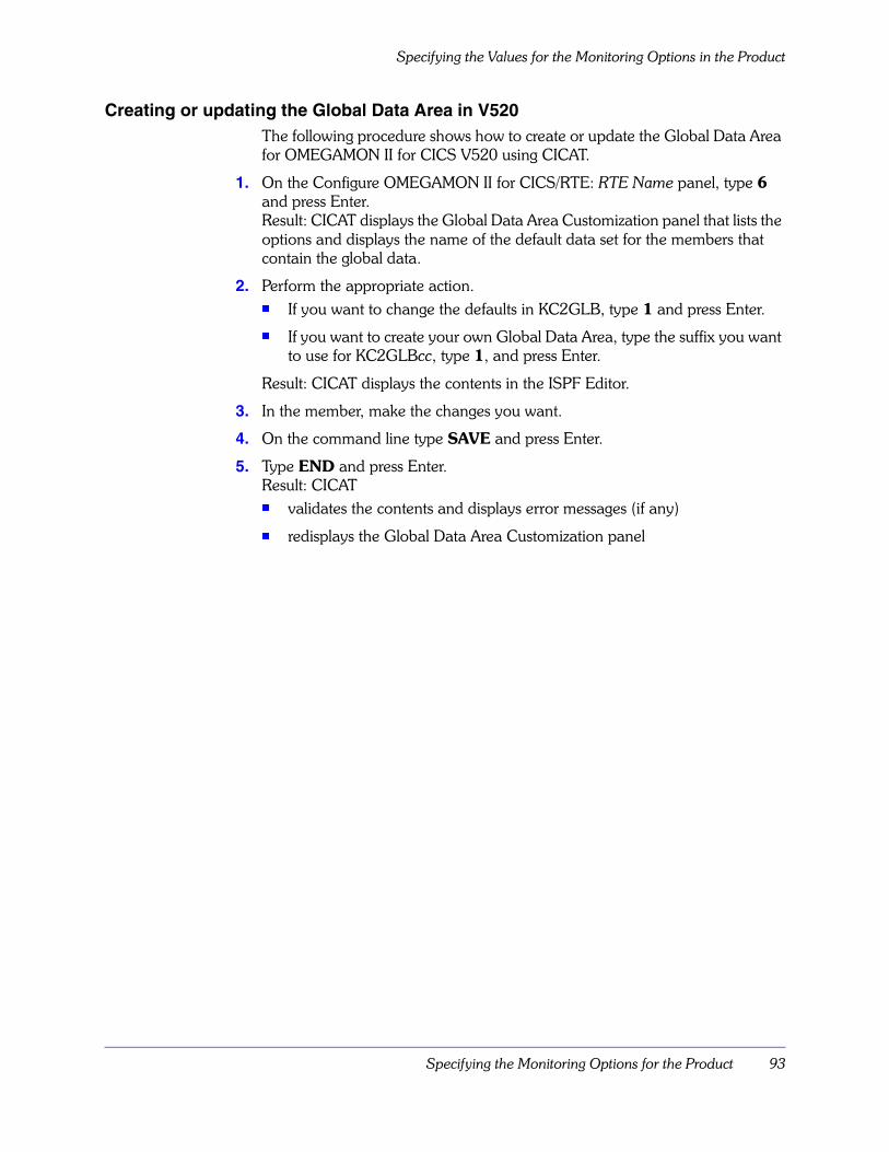
Specifying the Monitoring Options for the Product 93
Specifying the Values for the Monitoring Options in the Product
Creating or updating the Global Data Area in V520 The following procedure shows how to create or update the Global Data Area for OMEGAMON II for CICS V520 using CICAT.
1. On the Configure OMEGAMON II for CICS/RTE: RTE Name panel, type 6 and press Enter. Result: CICAT displays the Global Data Area Customization panel that lists the options and displays the name of the default data set for the members that contain the global data.
2. Perform the appropriate action.� If you want to change the defaults in KC2GLB, type 1 and press Enter.
� If you want to create your own Global Data Area, type the suffix you want to use for KC2GLBcc, type 1, and press Enter.
Result: CICAT displays the contents in the ISPF Editor.
3. In the member, make the changes you want.
4. On the command line type SAVE and press Enter.
5. Type END and press Enter. Result: CICAT � validates the contents and displays error messages (if any)
� redisplays the Global Data Area Customization panel
Specifying the Values for the Monitoring Options in the Product
94 OMEGAMON II for CICS Configuration and Customization Guide Version 520
Installing the Global Data Area in V520 Once you have created or updated the Global Data Area, follow this procedure to install the Global Data Area.
1. On the Configure OMEGAMON II for CICS/RTE: RTE Name panel, type 6 and press Enter. Result: CICAT displays the Global Data Area Customization panel that lists the options and displays the name of the default data set for the members that contain the new parameters.
2. On the Global Data Area Customization panel, type 3 and press Enter. Result: CICAT performs the following actions. � creates a list of the suffixes of the Global Data Areas installed for the RTE
(If you replicate the RTE using batch mode, CICAT also installs the Global Data Areas for the RTE when it is replicated.)
� copies the new members to rhilev.midlev.RKANPAR and displays the JCL for installing the Global Data Areas
3. Review the JCL.
4. On the command line, type SUBMIT and press Enter.
5. Exit CICAT. Result: CICAT installs the Global Data Areas. The next time you access CICAT, CICAT redisplays the Configure OMEGAMON II for CICS/RTE: RTE Name panel (if the job is complete). Once you have completed all the steps for the configuration, be sure to follow the instructions displayed when you select Complete the configuration (option 4) on the OMEGAMON II for CICS/RTE: RTE Name panel. These instructions contain information about specifying the Global Data Area in the CICS region JCL.

Specifying the Monitoring Options for the Product 95
Specifying the Values for the Monitoring Options in the Product
Saving the Global Data Area in V520 and aboveBeginning with V520, you can save the Global Data Area you are using in OMEGAMON II for CICS V520 using the CUA interface. You can then use the Global Data Area in the next version of OMEGAMON II for CICS.
Follow this procedure in OMEGAMON II V520 and above to save the Global Data Area.
1. Before you begin the installation of a higher version OMEGAMON II using CICAT, access the CUA interface for OMEGAMON II.
2. On the Region Status panel, tab to the Options menu and press Enter. Result: OMEGAMON II displays a drop-down menu.
3. On the drop-down menu, type 10 and press Enter. Result: OMEGAMON II displays the Save current Global setting panel that displays the suffix being used for the Global Data Area and the module name.
4. In the Save current global settings field, type Yes and press Enter. Result: OMEGAMON II � rewrites the Global Data Area so that the format is standard
(OMEGAMON II also removes comments you might have added.)
� validates the contents and displays information about errors (if any)
� saves the Global Data Area and displays the name of the module on a pop-up
5. Exit OMEGAMON II.
Refreshing the Monitoring Options
96 OMEGAMON II for CICS Configuration and Customization Guide Version 520
Refreshing the Monitoring Options OMEGAMON II uses the Global Data Area to load the information into MVS storage in the menu system interface address space on behalf of a monitored CICS region. Each region that OMEGAMON II monitors is represented by its own unique copy of the Global Data Area in the address space. This is true even if you defined only one module for monitoring multiple CICS regions. Each one of those regions has a separate, unique copy loaded for it at the time OMEGAMON II prepares to monitor it.
You can change the contents of a Global Data Area without stopping your CICS regions by assembling and linking your new module while the old one is being used.
You can delete a region’s Global Data Area copy from storage for the menu system and replace it with your updated version by performing any one of the following:
� Terminate the OMEGAMON II collector address space and restart it.
� Terminate the CICS address space and restart it.
� Stop OMEGAMON II from monitoring the target CICS while the CICS address space continues running normally.
To stop OMEGAMON II monitoring, perform all of the following steps:
1. If KOCOME00 was run at the CICS PLTPI time or if the OMEG INIT command was issued in the CICS region, issue an OMEG REMOVE command to reverse the process.
2. Stop task history collection, internal bottleneck collection, interval recording, and response time collection for the target CICS region. See the OMEGAMON II for CICS Reference Manual for instructions.
3. Terminate all OMEGAMON II sessions monitoring the target CICS region, including dedicated sessions. When this procedure is completed, OMEGAMON II deletes the Global Data Area copy used by the target CICS region. See “STOP command” on page 236 for details.
4. After completing the procedure, issue a new OMEG INIT command in the CICS address space to use the new Global Data Area.Note: Recycling the global module will only affect transactions started after the global has been recycled.

Specifying the Monitoring Options for the Product 97
Additional Considerations
Additional Considerations The tables below list CICS global exit names supported by EXIT_SUPPRESSION, the data gathered, CMF performance monitoring possibilities, and OMEG INIT processing implications.
Global exit names supported by EXIT_SUPPRESSION (CICS/MVS)The table below lists the CICS global user exit names supported by EXIT_SUPPRESSION, the type of data acquired, the OMEGAMON II components/commands affected, and Candle’s recommendation for exit suppression. Suppressing those exits with the recommendation “Do not suppress” will cause a loss of data for major functions such as RTA.
Note: TASK and KILL commands use TP I/O data for display only. Suppressing this data will not affect KILL functioning.
Table 19. CICS Global Exit Names Supported by EXIT_SUPPRESSION
Exit Name Data Type/Output Suppressed
Components Affected
Recommendation
XFCREQ File statistics ONDV/SMF Suppress
XSCREQ Storage statistics
Program compressions
ONDV/SMF
STOR/PCRT
Suppress
XKCREQ Response time
Program compressions
CPU utilizations
TP I/O data
Data delivery to the menu system
ONDV/SMF/RTA
STOR/PCRT
MAXR/RLIM
TASK/KILL
Do not suppress
XKCDISP Response time
CPU utilization
ONDV/SMF/RTA MAXR/RLIM
Do not suppress
XPCFTCH Program compressions SMF/STOR/PCRT Suppress
XTCIN Response time (BTAM) ONDV/SMF/RTA Do not suppress
XTCOUT TP I/O data (BTAM) ONDV/SMF TASK/KILL
Suppress
XTCTIN Response time (TCAM) ONDV/SMF/RTA Do not suppress
XTCTOUT TP I/O data (TCAM) ONDV/SMF TASK/KILL
Suppress
XZCIN Response time (VTAM) ONDV/SMF/RTA Do not suppress
XZCOUT1 TP I/O data (VTAM) ONDV/SMF TASK/KILL
Suppress
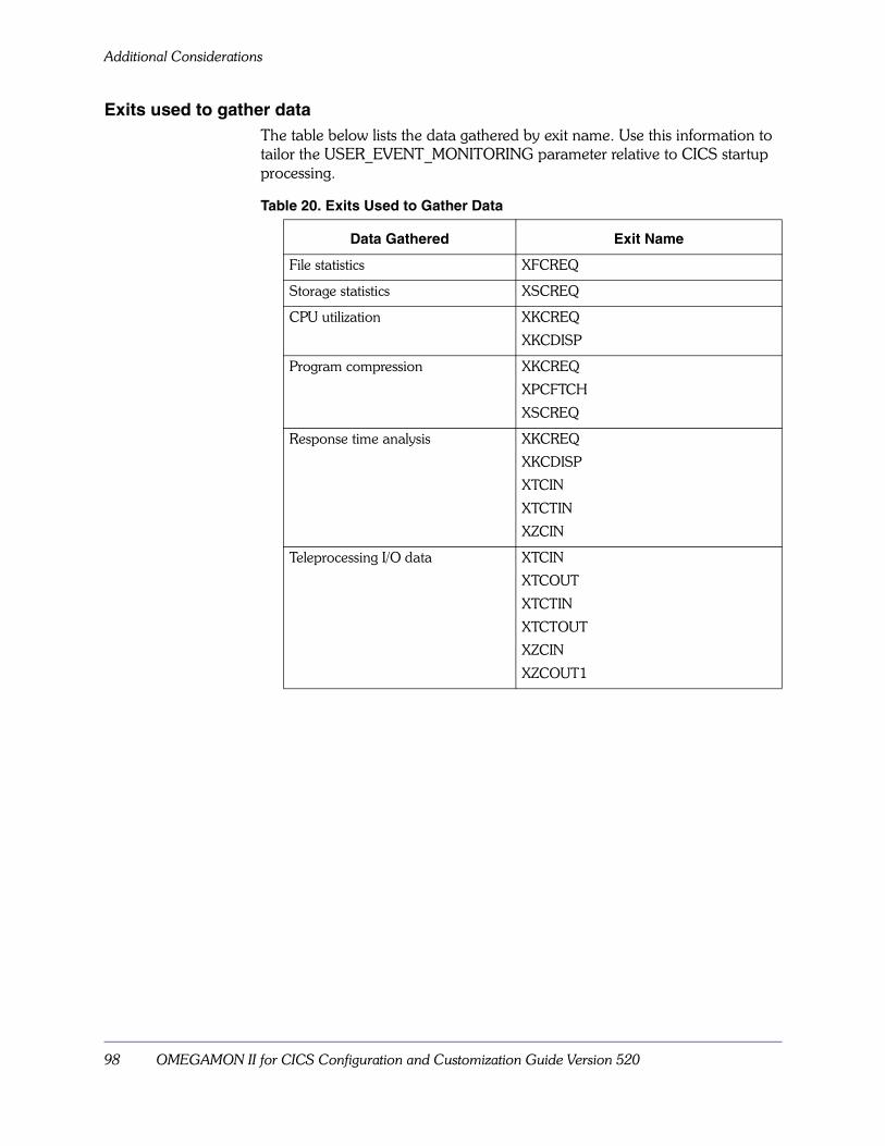
Additional Considerations
98 OMEGAMON II for CICS Configuration and Customization Guide Version 520
Exits used to gather dataThe table below lists the data gathered by exit name. Use this information to tailor the USER_EVENT_MONITORING parameter relative to CICS startup processing.
Table 20. Exits Used to Gather Data
Data Gathered Exit Name
File statistics XFCREQ
Storage statistics XSCREQ
CPU utilization XKCREQ
XKCDISP
Program compression XKCREQ
XPCFTCH
XSCREQ
Response time analysis XKCREQ
XKCDISP
XTCIN
XTCTIN
XZCIN
Teleprocessing I/O data XTCIN
XTCOUT
XTCTIN
XTCTOUT
XZCIN
XZCOUT1
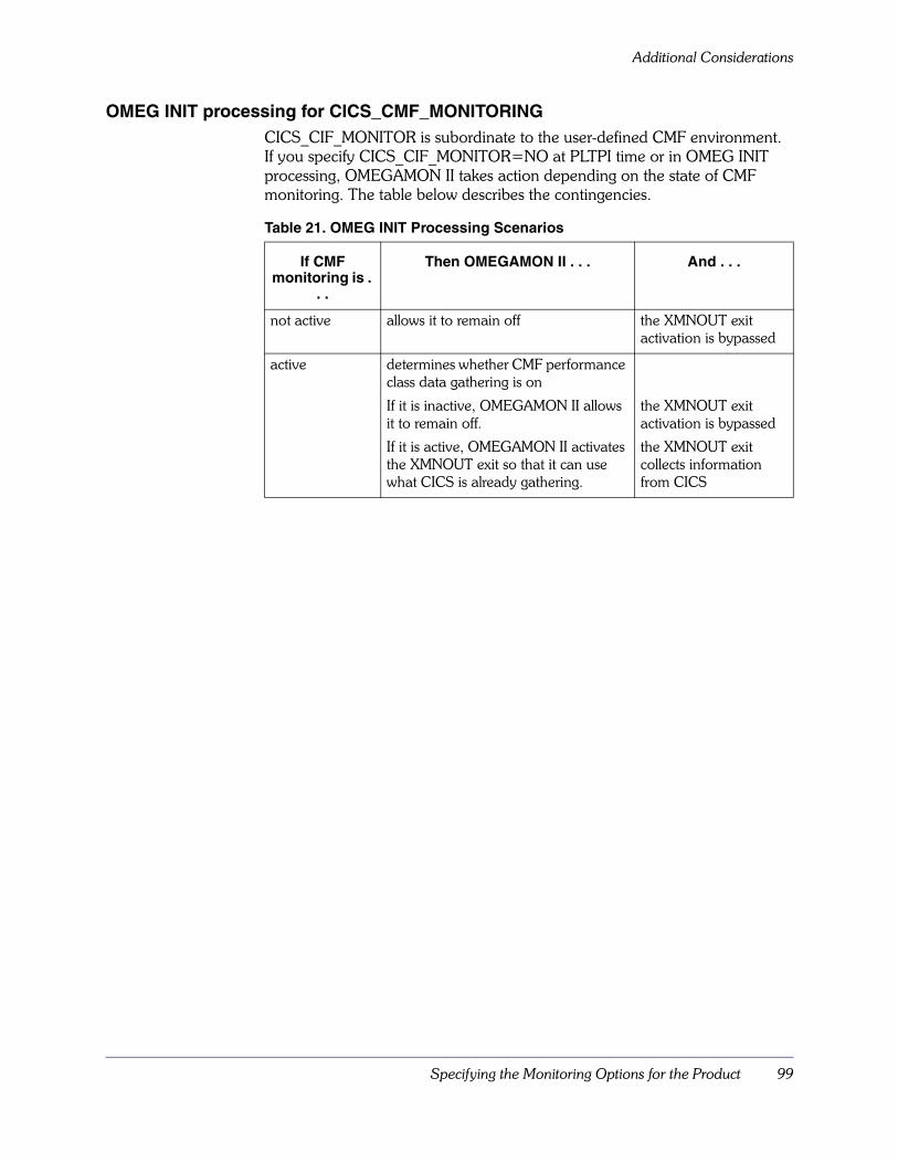
Specifying the Monitoring Options for the Product 99
Additional Considerations
OMEG INIT processing for CICS_CMF_MONITORINGCICS_CIF_MONITOR is subordinate to the user-defined CMF environment. If you specify CICS_CIF_MONITOR=NO at PLTPI time or in OMEG INIT processing, OMEGAMON II takes action depending on the state of CMF monitoring. The table below describes the contingencies.
Table 21. OMEG INIT Processing Scenarios
If CMF monitoring is .
. .
Then OMEGAMON II . . . And . . .
not active allows it to remain off the XMNOUT exit activation is bypassed
active determines whether CMF performance class data gathering is on
If it is inactive, OMEGAMON II allows it to remain off.
If it is active, OMEGAMON II activates the XMNOUT exit so that it can use what CICS is already gathering.
the XMNOUT exit activation is bypassed
the XMNOUT exit collects information from CICS

Additional Considerations
100 OMEGAMON II for CICS Configuration and Customization Guide Version 520
CMF monitoring possibilities (CICS/ESA)Several settings affect the monitoring and writing of CMF performance data:
� CMF performance monitoring parameters in your SIT (MN and MNPER SIT operands)
� CICSESA_SMF_RECORDS in USER_EVENT_MONITORING (YES or NO)
� CICS_CMF_MONITORING in USER_EVENT_MONITORING (YES or NO)
� CEMT SET MONITOR command (ON or OFF)
The following three tables illustrate the interaction of these factors.
1. The first table (Settings Before Initialization) shows the eight possible combinations of pre-initialization settings.
2. The second table (After OMEG INIT) shows what happens after you execute the OMEG INIT transaction to start OMEGAMON II. The first column indicates whether or not data will be written to SMF. The second column indicates whether or not data will be available to ONDV and RTA.
3. The third table (After CEMT SET MONITOR PERF ON) shows what happens if you execute CEMT SET MONITOR ON sometime after OMEGAMON II has been started.To determine how performance data will be handled with your current option settings, find the row in the first table that contains your pre-initialization settings. Then, check the corresponding row in the second and third tables.
Note: The letters OC stand for OMEGAMON II for CICS....
Table 22. After CEMT SET MONITOR PERF ON
SMF Write ONDV/RTA Get Data
Comments
YES NO XMNOUT is OFF.
N/A N/A Monitoring is already ON.
YES NO XMNOUT is OFF.
N/A N/A Monitoring is already ON.
N/A N/A Monitoring is already ON.
N/A N/A Monitoring is already ON.
N/A N/A Monitoring is already ON.
N/A N/A Monitoring is already ON.

Specifying the Monitoring Options for the Product 101
Additional Considerations
Table 23. After OMEG INIT
SMF Write ONDV/RTA Get Data
Comments
NO NO
NO YES CMF turned on. XMNOUT activated.
NO NO
YES YES CMF turned on. XMNOUT activated.
YES NO SMFCICS=NO.
NO YES
YES NO
YES YES CICS and OC write to SMF. All OC data collected. XMNOUT activated.
Table 24. Settings Before Initialization
CMF Perf. Monitoring SMFCICS3 MONITOR
OFF NO NO
OFF NO YES
OFF YES NO
OFF YES YES
ON NO NO
ON NO YES
ON YES NO
ON YES YES

Additional Considerations
102 OMEGAMON II for CICS Configuration and Customization Guide Version 520

Starting and Logging Onto the Product 103
Starting and Logging Onto the Product
Chapter OverviewThis chapter describes how to start and stop the OMEGAMON II menu system and CUA interface and any OMEGAMON II session running under either. As explained in “Modes of Operation” on page 53, the collector is a separate address space that controls OMEGAMON II operation.
Chapter ContentsStarting the Collector . . . . . . . . . . . . . . . . . . . . . . . . . . . . . . . . . . . . . . . 104Starting the CUA Interface (Optional) . . . . . . . . . . . . . . . . . . . . . . . . . . . 105Initializing the CICS Connection . . . . . . . . . . . . . . . . . . . . . . . . . . . . . . . 106The OMEGAMON II Service Task. . . . . . . . . . . . . . . . . . . . . . . . . . . . . . 107Stopping the Collector . . . . . . . . . . . . . . . . . . . . . . . . . . . . . . . . . . . . . . 108Stopping the CUA Interface . . . . . . . . . . . . . . . . . . . . . . . . . . . . . . . . . . 109Logging Onto the OMEGAMON II Menu System in VTAM Mode . . . . . . 110Logging Onto the OMEGAMON II Menu System in TSO Mode . . . . . . . 111Logging Onto the OMEGAMON II Menu System in ISPF Mode . . . . . . . 112Logging Onto the OMEGAMON II Menu System in Dedicated Mode . . . 113Simplified Signon . . . . . . . . . . . . . . . . . . . . . . . . . . . . . . . . . . . . . . . . . . 114Logging Off the Menu System in VTAM, TSO, or ISPF Mode . . . . . . . . . 118Logging Off the OMEGAMON II Menu System in Dedicated Mode . . . . 119Logging Off the CUA Interface . . . . . . . . . . . . . . . . . . . . . . . . . . . . . . . . 120
7
Starting the Collector
104 OMEGAMON II for CICS Configuration and Customization Guide Version 520
Starting the CollectorRegardless of how many modes of OMEGAMON II that you are running, you must start the collector only once. Sample JCL for starting the collector is supplied in rhilev.RKANSAM. The member has the started task name you specified for the OMEGAMON II for CICS menu system using CICAT. This should be copied to one of your procedure libraries.
We recommend that you start the collector automatically after each IPL. You can do this by adding a START command for the collector started task procedure to member COMMNDcc in SYS1.PARMLIB. Make the command similar to the one you use to start VTAM or other system tasks.
To start the collector manually, issue the following MVS console S (START) command:
S cccccccc
where ccccccc is the started task name you specified for the OMEGAMON II for CICS menu system using CICAT.

Starting and Logging Onto the Product 105
Starting the CUA Interface (Optional)
Starting the CUA Interface (Optional)Start the OMEGAMON II CUA interface by doing the following:
1. Activate the VTAM node for the CT/Engine by issuing the following command:
V NET,ACT,ID=cccccccc
where cccccccc is the major node name you specified for OMEGAMON II for CICS using CICAT.
2. Start the CUA interface address space by issuing the following command: S ccccccccc
where ccccccccc is the started task name you specified for the OMEGAMON II for CICS CUA interface using CICAT.
3. Test the OMEGAMON II CUA interface by issuing the following command:LOGON APPLID(KC2nnAP)
This command gives you access to the OMEGAMON II CUA interface through your VTAM attached terminal.
Initializing the CICS Connection
106 OMEGAMON II for CICS Configuration and Customization Guide Version 520
Initializing the CICS ConnectionBesides starting the collector, you must ensure that a connection is established between OMEGAMON II and the CICS region you intend to monitor. This connection is necessary to enable the response time collector, the interval record collector, and the task history collector.
The actions required depend on whether you start the collector before or after the CICS region has been initialized.
Starting before CICS initializesIf you start OMEGAMON II before CICS initializes, you can ensure that the collector is connected to the CICS region you are monitoring. The only qualification is that program KOCOME00 was added to the CICS PLT. (See “Defining the OMEGAMON II Program and Transaction” on page 73.)
Starting after CICS initializesIf you start OMEGAMON II after CICS initializes, you must start the collector and then establish a connection to the CICS region you are monitoring.
To connect the CICS region to the collector, issue the following CICS command:
OMEG INIT
Note: If you used an ID other than OMEG for your OMEGAMON II transaction, substitute that ID above (and wherever the OMEG transaction is mentioned in this manual).
When you start the collector, it automatically executes the series of commands. If you change the jobname of the collector, you must copy the member in rhilev.RKANPAR and give the new member the same name as the collector jobname.
This startup member (with the same name as the collector’s jobname) in rhilev.RKANPAR is processed automatically at initial region startup only.
After the collector has performed all actions defined in this startup member, you can issue other collector commands through the MVS MODIFY facility.
See “Collector Address Space” on page 227 for a description of the collector commands. See “Modifying the OBVTAM parameters” on page 54 for more information about connecting the collector.
Starting and Logging Onto the Product 107
The OMEGAMON II Service Task
The OMEGAMON II Service TaskOMEGAMON II uses service tasks to kill AIDS and ICEs, delete temporary storage queues, and delete transient data. Program KOCOME00 starts and terminates the OMEGAMON II service task, when invoked at PLTPI and PLTSD or when you enter OMEG INIT and OMEG SHUT at a terminal.
The OMEGAMON II service task contains two or more CICS tasks that have the OMEG transaction ID. OMEGAMON II umbrella transaction services distinguish between the main service task (OSRV) and the secondary service task (OSEC). If multiple users issue simultaneous requests to kill AIDS, up to 10 additional secondary tasks may be started to perform the requests. You need to adjust MXT and AMXT SIT parameters to allow for 11 additional tasks.
Note: You do not need to make changes to the PCT or CSD if you already defined the OMEG transaction ID (see “Defining the OMEGAMON II Program and Transaction” on page 73 for more information).
Using SRVSHUT and SRVINITYou can use the OMEG keywords SRVSHUT and SRVINIT to shutdown and start the service task without terminating or restarting the remainder of OMEG functions in the CICS address space.
OMEG SRVSHUT shuts down the service task, while allowing all other OMEG functions to remain available in the CICS address space (use this to shut down the service task instead of CEMT). OMEG SRVINIT starts the service task after it was shut down with OMEG SRVSHUT.
Stopping the Collector
108 OMEGAMON II for CICS Configuration and Customization Guide Version 520
Stopping the CollectorTo stop the collector manually, in all CICS regions connected to this collector address space, enter the following CICS command:
OMEG SHUT
and then use the MVS console P or STOP command:
P cccccccc
where cccccccc is the started task name you specified for the OMEGAMON II for CICS menu system using CICAT.
When you stop the collector, you deactivate the connection between the collector and each CICS region it is monitoring. If you restart the collector when the CICS region to be monitored is already running, the connection to the CICS region is not re-established. To re-establish this connection, see the instructions under “Starting after CICS initializes” on page 106.

Starting and Logging Onto the Product 109
Stopping the CUA Interface
Stopping the CUA InterfaceStop OMEGAMON II by doing the following:
1. Terminate any VTAM sessions you have in progress by following the exit instructions displayed on panel.
2. Stop the collector address space by issuing the following command:P cccccccc
where cccccccc is the started task name you specified for the OMEGAMON II for CICS menu system using CICAT.
3. Stop the CUA interface address space by issuing the following command:P ccccccccc
where cccccccc is the started task name you specified for the OMEGAMON II for CICS CUA interface using CICAT.
Note: If you receive the following message, be sure to reissue the command immediately:
KLVOP022, SHUTDOWN MUST BE CONFIRMED WITHIN 15 SECONDS

Logging Onto the OMEGAMON II Menu System in VTAM Mode
110 OMEGAMON II for CICS Configuration and Customization Guide Version 520
Logging Onto the OMEGAMON II Menu System in VTAM ModeTo log onto OMEGAMON II in VTAM mode, perform the following steps:
1. Activate the OBVTAM VTAM applid (KC2nnOC is the default) that was installed in“Modifying the OBVTAM parameters” on page 54.If the applid is not activated at VTAM initialization, vary the node active with the following command:
V NET,ACT,ID=cccccccc
where cccccccc is the name of the VTAM application major node.
2. Use the following command to start the collector, if it is not already started:S cccccccc
where cccccccc is the started task name you specified for the OMEGAMON II for CICS menu system using CICAT. (See“Starting the Collector” on page 104.)
Check the operator console to verify that OBVTAM started successfully. (Look for OMEGAMON II messages CI0510, CI0700, CI0720, and CI0760.)
3. Log onto an OMEGAMON II session.To log onto an OMEGAMON II session under VTAM, issue the following command on a VTAM terminal.
LOGON APPLID(aaaaaaaa) DATA(‘CICS=cccccccc’)
The syntax of the above command may vary at your installation.
The MVS console log indicates that the VTAM session has started. The OMEGAMON II copyright screen appears.
4. Press Enter to continue. OMEGAMON II is now running in VTAM mode.
aaaaaaaa The VTAM applid (KC2nnOC is the default) specified to OBVTAM when it was started.
cccccccc The CICS jobname to be monitored (optional if the default is specified in the KOCVTMnn member of rhilev.RKANPAR).
Starting and Logging Onto the Product 111
Logging Onto the OMEGAMON II Menu System in TSO Mode
Logging Onto the OMEGAMON II Menu System in TSO ModeTo log onto OMEGAMON II in TSO mode, perform the following steps:
1. Activate the VTAM applids that were installed in “Modifying the OBVTAM parameters” on page 54.
a. If the OBVTAM applid is not activated at VTAM initialization, vary the node active with the following command:
V NET,ACT,ID=cccccccc
where cccccccc is the name of the VTAM application major node for OBVTAM.
b. If the VTM1 applid is not activated at VTAM initialization time, vary the node active with the following command:
V NET,ACT,ID=cccccccc
where cccccccc is the name of the VTAM application major node for VTM1 (KOBVT1AP is the default).
Note: If you try to log onto OMEGAMON II and the VTAM application major node is not active, OBVTAM retries for up to 30 minutes, waiting for the applid to be varied active.
2. Use the following command to start the collector, if it is not already started:S cccccccc
where cccccccc is the started task name you specified for the OMEGAMON II for CICS menu system using CICAT. (See “Starting the Collector” on page 104.)
3. Invoke the following CLIST:%KOCLIST CICS(cccccccc)
where cccccccc is the CICS region that you want to monitor.
The Invocation Menu appears.
4. Select option 2 and fill in the other required fields to log onto OMEGAMON II.OMEGAMON II recognizes that you invoked KOCLIST in TSO mode, and the OMEGAMON II copyright screen appears.
5. Press Enter to continue.OMEGAMON II is now running in TSO mode.
Logging Onto the OMEGAMON II Menu System in ISPF Mode
112 OMEGAMON II for CICS Configuration and Customization Guide Version 520
Logging Onto the OMEGAMON II Menu System in ISPF ModeTo log onto OMEGAMON II in ISPF mode, perform the following steps:
1. Activate the VTAM applids that you installed in“Modifying the OBVTAM parameters” on page 54.
a. If the OBVTAM applid is not activated at VTAM initialization, vary the node active with the following command:
V NET,ACT,ID=cccccccc
where cccccccc is the name of the VTAM application major node for OBVTAM.
b. If the VTM1 applid is not activated at VTAM initialization time, vary the node active with the following command:
V NET,ACT,ID=cccccccc
where cccccccc is the name of the VTAM application major node for VTM1 (KOBVT1AP is the default).
Note: If you try to log ontoOMEGAMON II and the VTAM application major node is not active, OBVTAM retries for up to 30 minutes, waiting for the applid to be varied active.
2. Use the following command to start the collector, if it is not already started:S cccccccc
where cccccccc is the started task name you specified for the OMEGAMON II for CICS menu system using CICAT. (See “Starting the Collector” on page 104.)
3. To log onto an OMEGAMON II session under ISPF, choose one of the following methods: � If you installed a selection for OMEGAMON II on your site’s ISPF Primary
Options Menu, select OMEGAMON II on the menu to invoke KOCLIST.
� If OMEGAMON II is not a selection on your site’s ISPF Primary Options Menu, invoke the following CLIST:
%KOCLIST
The Invocation Menu appears.
4. Select option 2 and fill in the other required fields to log onto OMEGAMON II.OMEGAMON II recognizes that you invoked KOCLIST in ISPF mode, and the OMEGAMON II copyright screen appears.
5. Press Enter to continue.OMEGAMON II is now running in ISPF mode.
Starting and Logging Onto the Product 113
Logging Onto the OMEGAMON II Menu System in Dedicated Mode
Logging Onto the OMEGAMON II Menu System in Dedicated ModeTo log onto OMEGAMON II in dedicated mode, perform the following steps:
1. Verify that the terminal you use is not an MVS console and is not allocated to any other job or started task (including VTAM).Note: A dedicated OMEGAMON II session requires the use of a locally attached, non-SNA terminal.
2. Enter the MVS MODIFY command shown below:F cccccccc,EXEC cccccccc
where cccccccc is the started task name for the menu system and where ccccccccc is the name of the member in rhilev.RKANPAR that contains a START command. This member was modelled after rhilev.RKANSAM(KOCIDED), as described in “Installing in Dedicated Mode” on page 62.
3. Log onto an OMEGAMON II dedicated session with the MVS MODIFY command and specify the dedicated mode START options at that time. For example,
MODIFY cccccccc,START KOCCICS,CICS=CICSPROD,UNIT=cuu
or
F cccccccc,START KOCCICS,CICS=CICSPROD,UNIT=cuu
where cccccccc is the started task name you specified for the OMEGAMON II for CICS menu system using CICAT and where cuu represents the unit address of the terminal dedicated to OMEGAMON II.
The MVS console log indicates that the dedicated session has started. The OMEGAMON II copyright screen appears. The session automatically refreshes itself every few seconds.
4. Press Enter to continue.OMEGAMON II is now running in dedicated mode.
Simplified Signon
114 OMEGAMON II for CICS Configuration and Customization Guide Version 520
Simplified SignonThese pages describe the Simplified Signon feature. With this feature enabled, you will see the CICS Regions panel when you sign onto OMEGAMON II for CICS. From this panel, you can select a region to monitor.
Using Simplified Signon, you provide only your user ID and password when you sign onto OMEGAMON II for CICS. You no longer need to specify the OMEGAMON collector VTAM applid or the CICS jobname in the logon options.
Whenever you are using the CUA interface to monitor a CICS region, you can easily select another CICS region to monitor by using the region switch key (default PA1) to display the CICS Regions panel.
If the region you are monitoring terminates, the CICS Regions panel redisplays. You can then select another region to monitor or you can sign off.
RequirementsTo use simplified signon, the following are required:
� MVS/ESA
� OMEGAMON II for CICS CUA interface
Implementing simplified signon for an existing userIf OMEGAMON II for CICS is already installed at your site, use the following procedure to implement Simplified Signon:
1. Update the KC2IPAnn member of rhilev.RKANPAR as follows:OCII_COMMMON_INTERFACE_APPLID=*
CICS_JOB_NAME=*
2. If you want to restrict users from monitoring certain CICS regions, implement CUA Function Level Security and authorize users to monitor CICS regions, as required for your site. See Security for an existing user.
3. Recycle the CUA interface address space.
Security for an existing userIf you want to restrict CICS region access, you must:
1. Implement CUA Function Level Security as described in OMEGAMON II for CICS Configuration and Customization Guide.
2. In your external security manager (such as RACF, CA-ACF2, or CA-TOP SECRET), specify that your users can access CUA resource name
cicsname.KC2.REG.SWITCH
where cicsname is the applid of the CICS region the users can monitor.

Starting and Logging Onto the Product 115
Simplified Signon
Using simplified signonThe following paragraphs describe how to use the Simplified Signon feature.
Regions listed
For a region to be included on the CICS Regions panel:
� OMEGAMON II for CICS must be initialized in the CICS region by executing program KOCOME00 in the PLTPI or by executing transaction OMEG INIT.
� The CICS region must reside in the same MVS image as the address space for the CUA interface.
� When the CUA function level security is enabled, the current user must be authorized to monitor that region.
Selecting a region
After you sign on, the CICS Regions panel displays the CICS regions that you can monitor. Select the region you wish to monitor and press Enter.
FIGURE 7. CICS Regions Panel
If the region you want to monitor:
� is swapped out, Swapped is displayed in the CICS Applid field. Swapped out regions cannot be monitored.
� does not appear on the CICS Regions panel, press F11 (Logon Options) and then specify a common interface applid and a CICS jobname.
Switching regions
If you are already monitoring a region, use the following procedure to switch regions.
___ Actions View Options Help------------------------------------------------------------05/14/96 17:00:01KC2A01D CICS Regions
Auto(Off)+-----------+----------+---------+----------+----------+---------+----------+| CICS | CICS | CICS | Start | Start | KOCCI | Region || Jobname | Applid | Release | Date | Time | Applid | Profile |+-----------+----------+---------+----------+----------+---------+----------|| _ PRODS06 | PRODS06 | 3.3.0 | 05/14/96 | 07:36:18 | PRODS01 | $DEFAULT || _ PRODS07 | PRODS07 | 3.3.0 | 05/13/96 | 13:35:25 | PRODS02 | $DEFAULT || _ PRODS22 | PRODS22 | 3.2.1 | 05/13/96 | 09:53:47 | PRODS01 | $DEFAULT || _ PRODS55 | PRODS55 | 2.1.2 | 05/12/96 | 14:13:46 | PRODS02 | $DEFAULT || _ PRODS60 | PRODS60 | 4.1.0 | 05/12/96 | 14:30:50 | PRODS01 | $DEFAULT || _ PRODS66 | PRODS66 | 3.3.0 | 05/13/96 | 12:33:01 | PRODS01 | PRODS66 |+-----------+----------+---------+----------+----------+---------+----------+
F1=Help F2=Keys F3=Exit F5=Refresh F10=Action Bar F11=Logon Options

Simplified Signon
116 OMEGAMON II for CICS Configuration and Customization Guide Version 520
1. From any OMEGAMON II for CICS CUA interface panel, press the Region Switch Key; the default is PA1.The CICS Regions panel is displayed as shown in Selecting a region. In this case, the current region is displayed in the top right hand corner of the panel.
Note: You can modify the Region Switch Key on the Session Defaults pop-up under the Controls selection of the Options pulldown (fastpath OCS).
2. Select a region to monitor or return to the original region by pressing F12.
Sorting regions
When you are on the CICS Regions panel (see “Selecting a region” on page 115), you can use the View pulldown to select which regions to display and in what order.
FIGURE 8. View Pulldown Menu
Use this View pulldown to select all regions or only those regions matching your specified criteria, and to sort by any display column in ascending or descending order.
1 1. All2. Some...
1 1. Sort by CICS jobname2. Sort by CICS applid3. Sort by CICS release4. Sort by start date/time5. Sort by OMEGAMON applid6. Sort by region profile
Sort order1 1. Ascending
2. Descending
F1=Help F12=Cancel

Starting and Logging Onto the Product 117
Simplified Signon
Filtering regions
When you select View Some from the View pulldown, you can use the View Some pop-up to filter the CICS Regions display by CICS jobname, CICS applid, OMEGAMON applid, or region profile.
FIGURE 9. View Some Panel
You can specify selection criteria for any of these fields.
KC2A01VF View Some
Type any changes, then press Enter.
Field Operator + Value------------------ ---------- --------CICS jobname . . . EQ *_______CICS applid . . . EQ *_______OMEGAMON applid . EQ *_______Region profile . . EQ *_______ +
F1=Help F4=Prompt F5=Refresh F12=Cancel

Logging Off the Menu System in VTAM, TSO, or ISPF Mode
118 OMEGAMON II for CICS Configuration and Customization Guide Version 520
Logging Off the Menu System in VTAM, TSO, or ISPF ModeTo log off an OMEGAMON II session in VTAM, TSO, or ISPF mode, perform the following steps:
1. Press PF4 to return to the main menu of the menu system interface.
2. Select option X or type /stop on the INFO-line (top line) of any OMEGAMON II screen and press Enter.The OMEGAMON II session stops, but the collector remains active in the menu system if you want to start a session at a later time.
Starting and Logging Onto the Product 119
Logging Off the OMEGAMON II Menu System in Dedicated Mode
Logging Off the OMEGAMON II Menu System in Dedicated ModeUse the STOP command shown below to log off a dedicated monitoring session:
F cccccccc,STOP OCUcuu
where ccccccccc is the started task name you specified for the OMEGAMON II for CICS menu system using CICAT and cuu (3 or 4 characters, depending on how your system is genned) is the dedicated terminal address.
If the STOP command fails, add the FORCE option in the format:
F cccccccc,STOP OCUcuu,FORCE
where cccccccc is the started task name you specified for the OMEGAMON II for CICS menu system using CICAT.
Using the STOP command with the FORCE option terminates the object task with a system FFF abend.

Logging Off the CUA Interface
120 OMEGAMON II for CICS Configuration and Customization Guide Version 520
Logging Off the CUA InterfaceSee the OMEGAMON II for CICS User’s Guide for information on logging on and off the CUA interface.

Customizing CUA Interface Profiles 121
Customizing CUA Interface Profiles
Chapter OverviewThis chapter describes:
� the profiles that OMEGAMON II uses in the CUA interface
� how to specify a region profile
� how to migrate thresholds from the menu system interface
� how to switch profiles
� the Dynamic Profile Update Facility
See“Customizing Menu System Interface Profiles” on page 145 for information about menu system interface profiles.
You can perform the steps described in this chapter at installation or any time during an OMEGAMON II session.
Chapter ContentsAbout CUA Interface Profiles . . . . . . . . . . . . . . . . . . . . . . . . . . . . . . . . . 122Specifying a Region Profile and Migrating Thresholds. . . . . . . . . . . . . . . 123Switching Profiles . . . . . . . . . . . . . . . . . . . . . . . . . . . . . . . . . . . . . . . . . . 124Dynamic Profile Update Facility . . . . . . . . . . . . . . . . . . . . . . . . . . . . . . . 125$DEFAULT Region Profile . . . . . . . . . . . . . . . . . . . . . . . . . . . . . . . . . . . 126
Important
Remember to distinguish between the started task names for the menu system and CUA interface.
8

About CUA Interface Profiles
122 OMEGAMON II for CICS Configuration and Customization Guide Version 520
About CUA Interface ProfilesEvery session for the CUA interface uses two profiles:
� the userid profile
� the region profile
Note: OMEGAMON II provides default profiles ($DEFAULT) for the region and userid profiles. The default profiles cannot be modified.
Userid profilesThe userid profile defines the preferences and controls for the current session, such as print routing options.
After you change settings, OMEGAMON II prompts you to save them for the duration of the current session, or, if you are authorized, to save them in the userid profile.
To manage userid profiles, perform the following steps.
1. Select O from the action bar of any panel.
2. Select U from the Options menu.
3. Type an action code and press Enter.See the OMEGAMON II for CICS User’s Guide for more information about userid profiles.
Region profilesThe region profile defines the threshold settings for all performance measures for a given CICS region. The region profile is used by all user IDs that monitor a specific region.
After changing any threshold values, OMEGAMON II prompts you to save them for the duration of the current session, or, if you are authorized, to save them in the region profile.
To manage region profiles, perform the following steps.
1. Select O from the action bar of any panel.
2. Select R from the Options menu.
3. Type an action code and press Enter.See the OMEGAMON II for CICS User’s Guide for more information about copying, deleting, and printing region profiles.

Customizing CUA Interface Profiles 123
Specifying a Region Profile and Migrating Thresholds
Specifying a Region Profile and Migrating ThresholdsTo specify a region profile and optionally migrate menu system thresholds, complete the following steps:
1. Press F11 on the OMEGAMON II sign-on panel or the CICS Regions panel.The Logon Options pop-up window appears.
2. Enter the name of your choice in the CICS Region Profile field.Note: Skip steps 3 and 4 if you are a new user of Candle products or you do not want to use your site’s existing menu system thresholds in the CUA interface.
3. Enter Yes in the Migrate Profile from OMEGAMON II field.
4. In the OMEGAMON II Profile to Migrate From field, enter the 2-character suffix of the menu system profile (/C, /I, or cc) that you want to migrate.Note: Any changes you make override the default specified in the USER_PROFILE_SUFFIX= parameter of the KC2IPAnn member.
5. Press Enter to continue. See“Customizing Menu System Interface Profiles” on page 145 for information on menu system profiles.
Switching Profiles
124 OMEGAMON II for CICS Configuration and Customization Guide Version 520
Switching ProfilesWhen you switch the region you are monitoring, OMEGAMON II (by default) uses a region profile with the same name as the new region name. If OMEGAMON II cannot find a profile with the same name as the new region name, it uses the profile specified in KC2IPAnn. If a profile was not specified, it uses the $DEFAULT profile.
To switch profiles after you have started an OMEGAMON II session, perform the following steps:
1. Select O from the action bar of the Region Status panel.
2. Select option R.
3. Type the name of the desired region profile and press Enter, or enter S next to the desired profile.OMEGAMON II switches to the specified region profile.
Customizing CUA Interface Profiles 125
Dynamic Profile Update Facility
Dynamic Profile Update FacilityThe Dynamic Profile Update Facility allows users to export and import individual CUA profiles dynamically to and from a partitioned dataset. This facility can be invoked externally through an MVS console command.
See the OMEGAMON II for CICS User’s Guide for more information about this facility.
$DEFAULT Region Profile
126 OMEGAMON II for CICS Configuration and Customization Guide Version 520
$DEFAULT Region Profile The $DEFAULT region profile cannot be modified. OMEGAMON II for CICS uses the $DEFAULT region profile if:
� there is no region profile defined with the same name as the CICS region name
� the name for the region profile you selected is not valid
� a region profile is not defined in CICS_REGION_PROFILE in the member KC2IPAnn in rhilev.RKANPAR
� $DEFAULT is defined for CICS_REGION_PROFILE in the KC2IAnn member in rhilev.RKANPAR
If you do not want to use the $DEFAULT region profile provided with OMEGAMON II for CICS, follow these broad steps.
1. Create a region profile with the default thresholds appropriate for your site.
2. Specify the name of the region profile you created for CICS_REGION_PROFILE in KC2IPAnn.

Customizing CUA Interface Security 127
Customizing CUA Interface Security
Chapter OverviewThis chapter provides information to help you choose and implement a security facility that meets the requirements at your site. You can use the CUA interface security facility in conjunction with the menu system security facility (see “Function Level Security” on page 137 and “Menu System Security Facility” on page 161).
Chapter ContentsChoosing Your Security Configuration . . . . . . . . . . . . . . . . . . . . . . . . . . 128OMEGAMON II Internal Security . . . . . . . . . . . . . . . . . . . . . . . . . . . . . . 129CA-ACF2 External Security . . . . . . . . . . . . . . . . . . . . . . . . . . . . . . . . . . 131RACF External Security . . . . . . . . . . . . . . . . . . . . . . . . . . . . . . . . . . . . . 132CA-TOP SECRET External Security . . . . . . . . . . . . . . . . . . . . . . . . . . . . 133Bypassing CUA Interface Security. . . . . . . . . . . . . . . . . . . . . . . . . . . . . . 135
Important
Remember to distinguish between the started task names for the menu system and the CUA interface.
9

Choosing Your Security Configuration
128 OMEGAMON II for CICS Configuration and Customization Guide Version 520
Choosing Your Security ConfigurationCUA interface security provides a user ID and password validation capability to detect and prevent unauthorized access of the product. The OMEGAMON II Network Access Manager (NAM) is the default CUA interface security facility.
NAM provides security at the CUA interface (to prevent unauthorized access of OMEGAMON II), and OMEGAMON II provides command password protection for security at the menu system interface (to prevent unauthorized use of OMEGAMON II commands).
In choosing an appropriate security system for your site, you can:
� keep NAM and OMEGAMON II as the security systems for your site
� implement an external security package such as CA-ACF2 (also referred to as ACF2), RACF, or CA-TOP SECRET to replace NAM at the CUA interface
� implement an external security package to be used in conjunction with OMEGAMON II at the menu system interface
� choose to not implement security
To help you choose the right security system for your OMEGAMON II environment, we recommend that you see your security administrator for information about the types of security used at your site.
The following table shows the CUA interface security customization choices available for use with OMEGAMON II.
Important
Security should be implemented at both the CUA interface and the menu system interface whether you choose the security shipped with OMEGAMON II or an external security package.
Table 25. CUA Interface Security Choices
System Name Exit Required? Exit Name
NAM No None
CA-ACF2 Yes KLVA2NEV
RACF No None
CA-TOP SECRET Yes KLVTSNEV

Customizing CUA Interface Security 129
OMEGAMON II Internal Security
OMEGAMON II Internal SecurityThis section describes how to use the security system shipped with OMEGAMON II.
NAM CUA interface securityThe OMEGAMON II Network Access Manager (NAM) can serve as a standalone security system. NAM security functions at the CUA interface only.
Use the following steps to implement NAM security:
1. Use CICAT to access the Configure OMEGAMON II for CICS panel.
2. Select the Specify configuration values optionOMEGAMON II.
3. Select NAM as the Specify security option.
4. When you select the Create runtime members option from the Configure OMEGAMON II for CICS panel, member rhilev.RKANPAR(KC2NAMnn) is created, which contains the information needed to enable NAM security.
5. Define all authorized OMEGAMON II users to NAM. Remember to include your own user ID and password in this step as NAM will not assume them automatically.Issue the MVS MODIFY command from the MVS console as follows:
F cccccccc,NAM SET userid1 PASSWORD=password1
F cccccccc,NAM SET userid2 PASSWORD=password2
where cccccccc is the started task name you specified for the CUA interface using CICAT. You must issue this command for each new user of OMEGAMON II.
6. Log on to OMEGAMON II using your user ID and password. The password you set using the MVS MODIFY command will expire the first time you log on. Each user must set a new password to enter the product for the first time.NAM maintains a record of each user’s previous passwords. By default, the last eight passwords set by a user are kept on file, and new passwords cannot match any of the eight listed.
To change the number of old passwords checked before you allow an old password to be reused, change the value of the REUSEPW parameter in rhilev.RKANPAR(KC2NAMnn).
After implementing NAM security, maintain users and passwords as follows:
� To modify a user’s password, reissue the modify command you used to initially set the password.
� To delete a NAM user, enter the following command:
F ccccccccc,NAM DELETE userid
OMEGAMON II Internal Security
130 OMEGAMON II for CICS Configuration and Customization Guide Version 520
where cccccccc is the started task name you specified for the OMEGAMON II for CICS interface using CICAT.
� To control the number of times a user can logon before a change of password is required, add the EXPIRE=nn parameter to the NAM SET command. The default is 0 (no expiration).

Customizing CUA Interface Security 131
CA-ACF2 External Security
CA-ACF2 External SecurityThis section describes how to interface with the ACF2 external security system.
CA-ACF2 CUA interface securityFollow these steps to interface with ACF2 security validation at the CUA interface:
1. Use CICAT to access the Configure OMEGAMON II for CICS panel.
2. Select the Specify configuration values option to display the OMEGAMON II Runtime Parameters panel.
3. Select ACF2 as the Specify security option.
4. When you select the Create runtime members option from the CICAT Configure OMEGAMON II for CICS panel, member rhilev.RKANPAR(KC2NAMnn) is created, which contains the information needed to enable ACF2 security validation at the CUA interface.
5. Install the exit for ACF2 security validation. Member thilev.TKANSAM(KLVA2NEV) is the sample assembler interface to ACF2.Assemble and link KLVA2NEV with AC=1 into rhilev.RKANMODL. Member thilev.TKANSAM(KLV@ASM) contains assembly JCL that can be modified according to instructions in the member.
Note: ACF2 exits must be run with AMODE=31.
6. The multiuser system access control point used by OMEGAMON II, has all the characteristics of an ACF2 Multiple User Single Address Space System (MUSASS). That is, system access validations are initiated and enforced by the address space on behalf of the network user.Define OMEGAMON II as a MUSASS to ACF2. Follow this sequence from the TSO READY prompt:
When you see this: Type this and press Enter:
READY ACF
ACF SET LID
LID CH cccccccc MUSASSwhere cccccccc is the started task name you specified for the CUA interface using CICAT
LID END
RACF External Security
132 OMEGAMON II for CICS Configuration and Customization Guide Version 520
RACF External SecurityThis section describes how to interface with the RACF external security system.
RACF CUA interface securityFollow these steps to interface with RACF security at the CUA interface:
1. Use CICAT to access the Configure OMEGAMON II for CICS panel.
2. Select the Specify configuration values option to display the OMEGAMON II Runtime Parameters panel.
3. Select RACF as the Specify security option.
4. When you select the Create runtime members option from the CICAT Configure OMEGAMON II for CICS panel, member rhilev.RKANPAR(KC2NAMnn) is created, which contains the information needed to enable RACF security validation at the CUA interface.
5. RACF must give CONTROL authority to the VSAM files rhilev.RKC2NAnn, rhilev.RKC2TDnn, and rhilev.RKC2VLnn.If you specified RACF during the configuration process, this step was completed automatically.
Protecting the OMEGAMON II VTAM applidPerform the following steps to protect the OMEGAMON II applid.
Note: The default name for the CUA VTAM applid is KC2nnAP. If you select a different name, substitute that name for KC2nnAP in the subsequent steps.
1. Create the following profile in the APPL class:RDEFINE APPL KC2nnAP UACC(NONE)
2. Allocate READ access to the profile as follows:PERMIT KC2nnAP CLASS(APPL) ID(userid) ACCESS(READ)
3. Activate the APPL class as follows:SETROPTS CLASSACT(APPL)

Customizing CUA Interface Security 133
CA-TOP SECRET External Security
CA-TOP SECRET External SecurityThis section describes how to interface with the CA-TOP SECRET external security system.
CA-TOP SECRET CUA interface securityFollow these steps to interface with CA-TOP SECRET external security at the CUA interface:
1. Use CICAT to access the Configure OMEGAMON II for CICS panel.
2. Select the Specify configuration values option to display the OMEGAMON II Runtime Parameters panel.
3. Select TOPSECRET as the Specify security option.
4. When you select the Create runtime members option from the CICAT Configure OMEGAMON II for CICS panel, member rhilev.RKANPAR(KC2NAMnn) is created, which contains the information needed to enable CA-TOP SECRET security validation at the CUA interface.
5. Install the exit for CA-TOP SECRET security validation. Member thilev.TKANSAM(KLVTSNEV) is the sample assembler interface to CA-TOP SECRET.Assemble and link KLVTSNEV with AC=1 into the rhilev.RKANMODL library. Member thilev.TKANSAM(KLV@ASM) contains assembly JCL that you can modify according to instructions in the member.
Note: CA-TOP SECRET exits must be run with AMODE=31.
6. Define the OMEGAMON II address space as a started task in the STC record, along with the related master FACILITY ACID. For example, enter:
TSS ADD(STC) PROC(cccccccc) ACID(master facility acid)
where cccccccc is the started task name you specified for the OMEGAMON II for CICS CUA interface using CICAT.
7. (Optional) Define all the OMEGAMON II datasets you want protected to CA-TOP SECRET.Make sure the OMEGAMON II started task has access to them.
8. Define task as a FACILITY to CA-TOP SECRET in the Facility Matrix Table, where task is the started task name. If the name you define in the FACILITY statement is different from the started task name, see the appropriate CA-TOP SECRET documentation for information on setting up the FACILITY statement.
CA-TOP SECRET External Security
134 OMEGAMON II for CICS Configuration and Customization Guide Version 520
The following example shows the FACILITY statements from a production installation using CA-TOP SECRET as the security system:
Some of these statements may not be relevant to your system, and may need to be modified to fit your standards and configuration.
Important
The SIGN parameter on the FACILITY statement must be specified as SIGN(M), or CA-TOP SECRET may revoke user access. Also, verify that MODE=FAIL is set.
FACILITY(USER3=NAME=task)FACILITY(task=MODE=FAIL,ACTIVE,SHRPRF)FACILITY(task=PGM=KLV,NOASUBM,NOABEND,NOXDEF)FACILITY(task=ID=3,MULTIUSER,RES,WARNPW,SIGN(M))FACILITY(task=NOINSTDATA,NORNDPW,AUTHINIT,NOPROMPT,NOAUDIT,NOMRO)FACILITY(task=NOTSOC,LOG(INIT,SMF,MSG,SEC9))

Customizing CUA Interface Security 135
Bypassing CUA Interface Security
Bypassing CUA Interface SecurityFollow these steps to bypass CUA interface security:
1. Use CICAT to access the Configure OMEGAMON II for CICS panel.
2. Select the Specify configuration values option to display the OMEGAMON II Runtime Parameters panel.
3. Select NONE as the Specify security option.
4. When you select the Create runtime members option from the CICAT Configure OMEGAMON II for CICS panel, member rhilev.RKANPAR(KC2NAMnn) is created, which contains the information needed to bypass security validation at the CUA interface.

Bypassing CUA Interface Security
136 OMEGAMON II for CICS Configuration and Customization Guide Version 520

Function Level Security 137
Function Level Security
Chapter OverviewThis chapter provides information about the function level security feature of the CUA interface and explains how to enable the feature.
Chapter ContentsBackground about Function Level Security. . . . . . . . . . . . . . . . . . . . . . . 138Enabling CUA function level security . . . . . . . . . . . . . . . . . . . . . . . . . . . 139CUA Function Level and Menu System Security . . . . . . . . . . . . . . . . . . . 140Authorizing User Access Example . . . . . . . . . . . . . . . . . . . . . . . . . . . . . . 141External Security Function Level Resources . . . . . . . . . . . . . . . . . . . . . . 142
10

Background about Function Level Security
138 OMEGAMON II for CICS Configuration and Customization Guide Version 520
Background about Function Level SecurityCUA function level security enables a security administrator to restrict access, by user, to functions, such as killing tasks, within the CUA component by defining resource rules to an external security manager like CA-ACF2, RACF, or CA-TOP SECRET.
When a user attempts to perform an unauthorized function, a message is displayed and the function is not performed. The message states that the function is protected and gives the resource name. For example:
User CICSUSER is not authorized to perform
this function. Contact your Security
Administrator with the following information:
Resource Name = cicsappl.KC2.KILL.TASK
You must first enable sign-on security through an external security manager such as CA-ACF2, RACF or CA-TOP SECRET to use this feature. See “Customizing CUA Interface Security” on page 127.

Function Level Security 139
Enabling CUA function level security
Enabling CUA function level securityFunction level security is automatically enabled if you take the following steps during CICAT configuration:
1. Use CICAT to access the Configure OMEGAMON II for CICS panel.
2. Select the Specify configuration values option to display the OMEGAMON II Runtime Parameters panel.
3. Enter a resource class name for the Function level security resource class option.
CUA Function Level and Menu System Security
140 OMEGAMON II for CICS Configuration and Customization Guide Version 520
CUA Function Level and Menu System SecurityYou can implement security in three different ways:
� Implement security exclusively in the menu system.
If you do this, the designated menu system commands are secured if the user attempts to issue them while using the menu system interface, and the corresponding resources are also secured if the user attempts to access them while using the CUA interface.
� Implement CUA function-level security exclusively.
If you do this, the designated CUA function-level resources are secured if the user attempts to access them while using the CUA interface. The corresponding commands are not secured if the user attempts to issue them while using the menu system interface.
� Implement both menu system and function-level security.
If you do this, the designed menu system commands are secured only if the user attempts to issue them while using the menu system interface. The corresponding resources are not secured if the user attempts to access them using the CUA interface, unless they have also been secured with CUA function-level security.
Likewise, the designated CUA function-level resources are secured only if the user attempts to access these resources while using the CUA interface. The corresponding commands are not secured if the user attempts to issue them while using the menu system interface, unless they have also been secured with menu system security.

Function Level Security 141
Authorizing User Access Example
Authorizing User Access ExampleAuthorizing user access requires that the administrator of your external security manager perform the following procedure:
1. Define the resource class name to your security package before CUA function level security is operable.To accommodate the names of all resources, set the MAXLNTH keyword for the ICHERCDE macro to 24. See “Modifying RACF and CA-ACF2 rules” on page 169 for more information about the ICHERCDE macro.
2. Define user access to specific functions.The following example shows how to authorize a user (USR1) access to the CUA task kill function using RACF.
RDEFINE nnnnnnnn cicsappl.KC2.KILL.TASK UACC(NONE)
PERMIT cicsappl.KC2.KILL.TASK CLASS(nnnnnnnn) ID(USR1) ACCESS(READ)
where
� nnnnnnnn is the resource class name
� cicsappl is the CICS applid
� cicsappl. KC2.KILL.TASK is the resource name
For the list of CUA functions you can protect and their resource names, see Table 26: External Security Function Level Resources on page 142.

External Security Function Level Resources
142 OMEGAMON II for CICS Configuration and Customization Guide Version 520
External Security Function Level ResourcesThe following table lists the resource names you can define to protect CUA panel functions, where cicsappl is the CICS applid and profile is the region profile or userid profile name.
Table 26. External Security Function Level Resources
Panel or Action Resource Name Protected Function
OMEGAMON zoom cicsappl.KC2.ZOOM Zoom from the CUA to the OMEGAMON menu system
Session Defaults cicsappl.KC2.AUTOINT Modify the auto refresh interval
Collection Controls cicsappl.KC2.COLLECT Modify any of the collection controls:� Internal bottleneck collection� Internal bottleneck display controls� Response time collection� Interval recording� Task history collection� CICS file/database collection� Resource Limiting� Monitoring control� VSAM analysis� Storage violation analysis� Dump analysis
CICS Shutdown Option cicsappl.KC2.SHUTDOWN Modify the CICS shutdown option
Response Time Groups cicsappl.KC2.RESPGRP Modify, delete or copy response time group information or response time element definitions
Userid Profiles profile.KC2.UPROF.DEL Delete userid profiles
Userid Profiles profile.KC2.UPROF.COPY Copy userid profiles
Userid Profiles profile.KC2.UPROF.PORT Export or import userid profiles
Region Profiles profile.KC2.RPROF.DEL Delete region profiles
Region Profiles profile.KC2.RPROF.COPY Copy region profiles
Region Profiles profile.KC2.RPROF.PORT Export or import region profiles
Threshold pop-ups profile.KC2.RPROF.SAVE Change threshold settings and save them to the current region profile. Threshold changes are only permitted for the current session.
� View � View Some� Print Output Routing Options� Session Defaults
profile.KC2.UPROF.SAVE Save the following to the current userid profile:� Sort criteria� Filter criteria� Routing options� Session defaults

Function Level Security 143
External Security Function Level Resources
Region Status cicsappl.KC2.REG.SWITCH Log onto, monitor, or switch monitoring to the specified region name
System Console cicsappl.KC2.CONSOLE Enter console commands
Automatic Initiate Descriptors (AIDs)
cicsappl.KC2.KILL.AIDS Kill AIDs entries
Interval Control Elements (ICEs)
cicsappl.KC2.KILL.ICES Kill ICEs
Task panels cicsappl.KC2.KILL.TASK Kill tasks
Temporary Storage Queues
cicsappl.KC2.DELETE.TSQ Delete Temporary Storage Queues
Destination Control Table (DCT)
cicsappl.KC2.DELETE.TDQ Delete Intrapartition Transient Data Queues
Zap Memory cicsappl.KC2.MEM.ST.ZAP Modify either OMEGAMON II memory or CICS memory
OMEGAMON II for CICS Memory or CICS Memory
cicsappl.KC2.MEM.ST.READ View either OMEGAMON II memory or CICS memory
Zap Dataspace Memory cicsappl.KC2.MEM.DS.ZAP Modify CICS dataspace memory
Dataspace Memory cicsappl.KC2.MEM.DS.READ View CICS dataspace memory
CICS Master Terminal cicsappl.KC2.MEM.CEMT Modify CEMT master terminal settings
Application Trace cicsappl.KC2.TRACE Modify status of application trace
Table 26. External Security Function Level Resources
Panel or Action Resource Name Protected Function

External Security Function Level Resources
144 OMEGAMON II for CICS Configuration and Customization Guide Version 520

Customizing Menu System Interface Profiles 145
Customizing Menu SystemInterface Profiles
Chapter OverviewThe menu system interface profiles control the characteristics of an active OMEGAMON II session. Both the installer and the general user community can create and save these customized profiles. This chapter describes the types of profiles, how to create them, and how to use profile security.
You can use these profiles exclusively in the menu system interface or you can migrate their thresholds to the CUA interface.
Note: If you plan to use the CUA interface, Candle recommends that you perform profile customization in the CUA interface (see “Customizing CUA Interface Profiles” on page 121). The CUA profiles override settings defined in the menu system interface profiles.
Chapter ContentsBackground about Profiles . . . . . . . . . . . . . . . . . . . . . . . . . . . . . . . . . . . 146Creating an Installation-Defined Profile . . . . . . . . . . . . . . . . . . . . . . . . . . 148Saving the Installation-Defined Profile. . . . . . . . . . . . . . . . . . . . . . . . . . . 150Profile Security . . . . . . . . . . . . . . . . . . . . . . . . . . . . . . . . . . . . . . . . . . . . 151
11

Background about Profiles
146 OMEGAMON II for CICS Configuration and Customization Guide Version 520
Background about Profiles
Types of profilesThere are three types of menu system interface profiles:
� The Candle-supplied profile contains session configuration defaults and default exception analysis thresholds. It enables you to easily install OMEGAMON II without customization and assures that users can always initialize an OMEGAMON II session, even if no other profiles are defined.
� The installation-defined profile enables you, the customizer, to define default settings that are different from the Candle-supplied profile settings. This customized profile becomes the default for all OMEGAMON II sessions at your installation. It takes precedence over the Candle-supplied profile.
� The user-defined profile allows individual OMEGAMON II users to create one or more profiles to customize their individual OMEGAMON II sessions. It takes precedence over the installation- and Candle-supplied profiles.
The Candle-supplied profile is always available and cannot be changed. The other profiles are optional and can exist independent of one another.
Profile suffixEach profile has a unique 2-character suffix. The suffixes for the three types of menu system interface profiles are:
The profile suffixes are used in the following locations:
� On the INFO-line display. The current session’s profile suffix appears on the INFO-line next to the product version number:
In this example, the installation profile (/I) is in effect.
� On the USER= parameter in your OMEGAMON II startup JCL or CLIST (see“Modifying the OBVTAM parameters” on page 54 for more information). For example, if you want to start a session with the user profile cc, enter USER=cc.
� On the USER=cc option on the ISPF Invocation Menu.
/C Candle-supplied profile.
/I Installation-defined profile.
cc User-defined profiles—any two alphanumeric characters.
______________ ZMENU VTM LOG OC V300./I SYSA 09/19/99 0:3 2:22 5 AB

Customizing Menu System Interface Profiles 147
Background about Profiles
� The user profile-defined suffix (cc) is specified in the Save/Delete option on the Profile menu in the menu system interface which saves and deletes user-defined profiles.
Profile search orderWhen OMEGAMON II is initialized, it always loads the Candle-supplied profile, as well as the installation-defined profiles and user-defined profiles, if they exist. To see which profile to use, OMEGAMON II checks the value on the USER start parameter (see “Modifying the OBVTAM parameters” on page 54 for more information).
� If a user-defined profile (cc) is specified, and OMEGAMON II is not able to find the user member, it searches for the /I profile. If no installation-defined profile is found, it defaults to /C.
� If no user-defined profile is specified, OMEGAMON II uses the installation-defined profile (/I). If no installation-defined profile is found, the profile defaults to /C, the Candle-supplied profile.
� If /C is specified, OMEGAMON II uses the Candle-supplied profile.
Profile storageThe Candle-supplied profile is stored in the load library and cannot be changed. Therefore, the Candle-supplied values are always available as shipped.
OMEGAMON II stores the installation-defined and user-defined profiles in your site’s profile dataset (rhilev.RKC2PFnn), which is referenced by ddname RKOCPFSV.
The installation-defined profile is stored as member OCINSTAL in rhilev.RKC2PFnn. The user-defined profiles are stored as member names in the form OCUSERcc, where cc is the user-defined profile suffix.
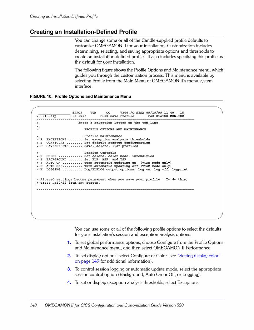
Creating an Installation-Defined Profile
148 OMEGAMON II for CICS Configuration and Customization Guide Version 520
Creating an Installation-Defined ProfileYou can change some or all of the Candle-supplied profile defaults to customize OMEGAMON II for your installation. Customization includes determining, selecting, and saving appropriate options and thresholds to create an installation-defined profile. It also includes specifying this profile as the default for your installation.
The following figure shows the Profile Options and Maintenance menu, which guides you through the customization process. This menu is available by selecting Profile from the Main Menu of OMEGAMON II’s menu system interface.
FIGURE 10. Profile Options and Maintenance Menu
You can use some or all of the following profile options to select the defaults for your installation’s session and exception analysis options.
1. To set global performance options, choose Configure from the Profile Options and Maintenance menu, and then select OMEGAMON II Performance.
2. To set display options, select Configure or Color (see “Setting display color” on page 149 for additional information).
3. To control session logging or automatic update mode, select the appropriate session control option (Background, Auto On or Off, or Logging).
4. To set or display exception analysis thresholds, select Exceptions.
________________ ZPROF VTM OC V300./C SYSA 09/19/99 11:40 :15> PF1 Help PF3 Exit PF10 Save Profile PA2 STATUS MONITOR===============================================================================> Enter a selection letter on the top line.>> PROFILE OPTIONS AND MAINTENANCE
> Profile Maintenance> A EXCEPTIONS ....... Set exception analysis thresholds> B CONFIGURE ........ Set default startup configuration> C SAVE/DELETE ...... Save, delete, list profiles
> Session Controls> D COLOR ............ Set colors, color mode, intensities> E BACKGROUND ....... Set XLF, ASF, and TSF> F AUTO ON .......... Turn automatic updating on (VTAM mode only)> G AUTO OFF.......... Turn automatic updating off (VTAM mode only)> H LOGGING .......... Log/XLFLOG output options, log on, log off, logprint
> Altered settings become permanent when you save your profile. To do this,> press PF10/22 from any screen.
===============================================================================

Customizing Menu System Interface Profiles 149
Creating an Installation-Defined Profile
Setting display colorTo set the display colors for an installation-defined profile, you must specify that you are setting color for a profile, not just for the current session. All profile option selections are saved when you follow the instructions in “Saving the Installation-Defined Profile” on page 150.
Select option D, Color, from the Profile Options and Maintenance menu. The Set Screen Colors and Definition Mode panel displays.
FIGURE 11. Set Screen Colors and Definition Mode Menu Option
To set screen colors for a profile, you must turn on Profile Definition Mode. To do this, overtype the setting of the ProfileDefinitionMode parameter so that it reads as follows:
ProfileDefinitionMode=ON
Once you have turned on Profile Definition Mode, you can set the display colors and save the settings to a profile. If you do not want your changes saved to a profile, turn Profile Definition Mode off. Then your color settings will be saved for the current session only.
Note: Profile Definition Mode does not apply to any other profile options.
________________ ZPCOLOR VTM $CICSTOR V300./I SYSA 09/19/99 17:38: 04> PF1 Help PF3 Back PF4 Main Menu PF7 Up PF8 Down PF10 Save
> A-Set Colors B-Set Extended Color C-Set Basic Color D-Turn Off Color===============================================================================> SET SCREEN COLORS AND DEFINITION MODE
> You may reassign the color designation as shown below by overtyping the COLOR> shown with your color of choice. Your choice consists of the seven supported> colors which are red, yellow, green, blue, turquoise, pink, and the standard> default color white.
.SCC: Display=COLOR ProfileDefinitionMode=OFF: ExtendedHighlighting=ON+: Major=YELLOW Minor=TURQUOISE Immed=TURQUOISE Default=TURQUOISE++ XACB Display Options:: Clr1=RED Clr2=YELLOW Clr3=BLUE Clr4=GREEN: Clr5=TURQUOISE Clr6=PINK Clr7=WHITE===============================================================================
Saving the Installation-Defined Profile
150 OMEGAMON II for CICS Configuration and Customization Guide Version 520
Saving the Installation-Defined ProfileYou can change the setting of any installation-defined profile option at any time during an OMEGAMON II session. OMEGAMON II uses the changed setting for the duration of the current session. (The only exception is the Pagefix option. A change to this option does not take place until the next OMEGAMON II session.)
If you want to use the changed profile after your OMEGAMON II session ends, you must save the profile by selecting the Save/Delete option of the Profile Options and Maintenance menu.
Note: The saved profile picks up not only the settings you changed, but all of the current settings for all profile options on the Profile Options and Maintenance menu. Be sure that you have changed only those settings you want to keep in the new profile before saving the profile.
To specify this new profile as the default for your installation, enter USER=/I in your OMEGAMON II startup JCL or CLIST. See “Modes of Operation” on page 53for information on modifying your startup parameters.
If you want to change or delete a profile, select the Save/Delete option on the Profile Options menu also.
Creating a user-defined profileIndividual users may want to create their own profiles to use when they are monitoring CICS with OMEGAMON II. For information on creating user-defined profiles, see the OMEGAMON II for CICS Reference Manual.
Customizing Menu System Interface Profiles 151
Profile Security
Profile SecurityCandle ships OMEGAMON II with the IPRF and IOPT commands unsecured, so that you can easily install and modify the installation-defined profile. These commands control installation-defined profiles. Once you create an installation-defined profile, you may want to protect it from inadvertent damage or modification by the general user community. Since each user can create a unique user-defined profile to override the installation-defined profiles and Candle-supplied profiles, he or she has no need to access the installation-defined profile.
To protect the installation-defined profile, you can use either OMEGAMON II’s default internal security or OMEGAMON II’s interface to external security packages, such as RACF or CA-ACF2. Candle’s internal security requires a password for authorization to issue a command. An external security package checks authorization via the user ID and logon password.
See “Menu System Security Facility” on page 161 for complete information about OMEGAMON II’s security feature.
Profile Security
152 OMEGAMON II for CICS Configuration and Customization Guide Version 520

Enabling Monitoring for User Defined Events 153
Enabling Monitoring forUser Defined Events
Chapter OverviewThis chapter contains information about enabling the monitoring for user-defined events. Monitoring for user-defined events allows you to monitor the performance of CICS applications and display the results you are monitoring on the displays in OMEGAMON II for CICS.
Chapter ContentsBackground about Monitoring for User-Defined Events . . . . . . . . . . . . . . . . . . . . . . 154Overview of the Process for Monitoring for a User-Defined Event . . . . . . . . . . . . . . . 155Specifying the User-Defined Event and Parameters for the Event . . . . . . . . . . . . . . . 156Specifying the Call to the Subroutine in the Application . . . . . . . . . . . . . . . . . . . . . . 157
12

Background about Monitoring for User-Defined Events
154 OMEGAMON II for CICS Configuration and Customization Guide Version 520
Background about Monitoring for User-Defined Events
When you enable monitoring for user-defined events, you can monitor any event in a CICS application. You can use the feature to
� collect clock and counter statistics for an event and up to 10 functions for the event
� display the results in OMEGAMON II for CICS
The clock and counter statistics are displayed in the following locations in OMEGAMON II for CICS.
� Task File Statistics Eventname panel
� Task History panel
� Task History Details panel
� Task History Eventname Resources panel
� Task History Eventname Details panel
� Application Trace panel
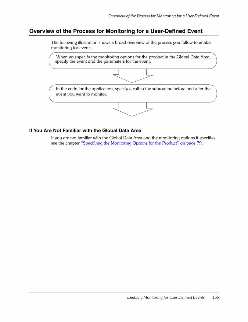
Enabling Monitoring for User Defined Events 155
Overview of the Process for Monitoring for a User-Defined Event
Overview of the Process for Monitoring for a User-Defined Event
The following illustration shows a broad overview of the process you follow to enable monitoring for events.
If You Are Not Familiar with the Global Data Area If you are not familiar with the Global Data Area and the monitoring options it specifies, see the chapter “Specifying the Monitoring Options for the Product” on page 79.
When you specify the monitoring options for the product in the Global Data Area, specify the event and the parameters for the event.
In the code for the application, specify a call to the subroutine before and after the event you want to monitor.
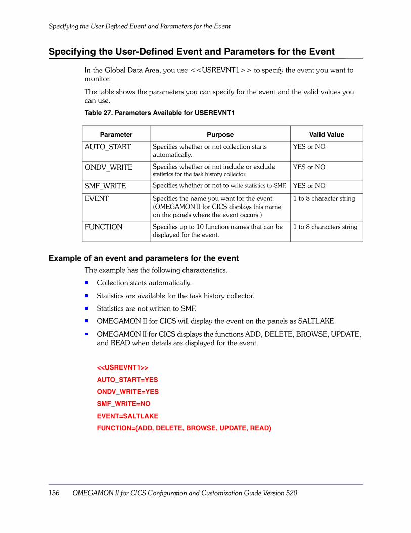
Specifying the User-Defined Event and Parameters for the Event
156 OMEGAMON II for CICS Configuration and Customization Guide Version 520
Specifying the User-Defined Event and Parameters for the Event
In the Global Data Area, you use <<USREVNT1>> to specify the event you want to monitor.
The table shows the parameters you can specify for the event and the valid values you can use.
Table 27. Parameters Available for USEREVNT1
Example of an event and parameters for the event The example has the following characteristics.
� Collection starts automatically.
� Statistics are available for the task history collector.
� Statistics are not written to SMF.
� OMEGAMON II for CICS will display the event on the panels as SALTLAKE.
� OMEGAMON II for CICS displays the functions ADD, DELETE, BROWSE, UPDATE, and READ when details are displayed for the event.
<<USREVNT1>>
AUTO_START=YES
ONDV_WRITE=YES
SMF_WRITE=NO
EVENT=SALTLAKE
FUNCTION=(ADD, DELETE, BROWSE, UPDATE, READ)
Parameter Purpose Valid Value
AUTO_START Specifies whether or not collection starts automatically.
YES or NO
ONDV_WRITE Specifies whether or not include or exclude statistics for the task history collector.
YES or NO
SMF_WRITE Specifies whether or not to write statistics to SMF. YES or NO
EVENT Specifies the name you want for the event. (OMEGAMON II for CICS displays this name on the panels where the event occurs.)
1 to 8 character string
FUNCTION Specifies up to 10 function names that can be displayed for the event.
1 to 8 characters string
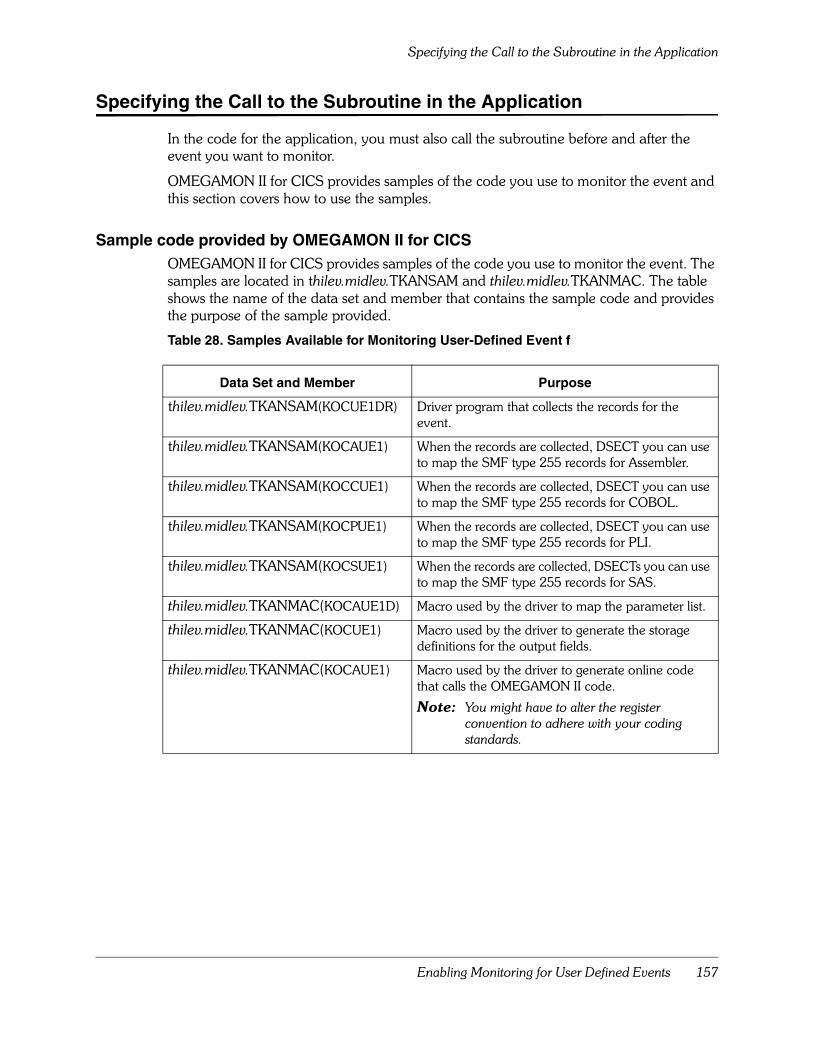
Enabling Monitoring for User Defined Events 157
Specifying the Call to the Subroutine in the Application
Specifying the Call to the Subroutine in the Application
In the code for the application, you must also call the subroutine before and after the event you want to monitor.
OMEGAMON II for CICS provides samples of the code you use to monitor the event and this section covers how to use the samples.
Sample code provided by OMEGAMON II for CICSOMEGAMON II for CICS provides samples of the code you use to monitor the event. The samples are located in thilev.midlev.TKANSAM and thilev.midlev.TKANMAC. The table shows the name of the data set and member that contains the sample code and provides the purpose of the sample provided.
Table 28. Samples Available for Monitoring User-Defined Event f
Data Set and Member Purpose
thilev.midlev.TKANSAM(KOCUE1DR) Driver program that collects the records for the event.
thilev.midlev.TKANSAM(KOCAUE1) When the records are collected, DSECT you can use to map the SMF type 255 records for Assembler.
thilev.midlev.TKANSAM(KOCCUE1) When the records are collected, DSECT you can use to map the SMF type 255 records for COBOL.
thilev.midlev.TKANSAM(KOCPUE1) When the records are collected, DSECT you can use to map the SMF type 255 records for PLI.
thilev.midlev.TKANSAM(KOCSUE1) When the records are collected, DSECTs you can use to map the SMF type 255 records for SAS.
thilev.midlev.TKANMAC(KOCAUE1D) Macro used by the driver to map the parameter list.
thilev.midlev.TKANMAC(KOCUE1) Macro used by the driver to generate the storage definitions for the output fields.
thilev.midlev.TKANMAC(KOCAUE1) Macro used by the driver to generate online code that calls the OMEGAMON II code.
Note: You might have to alter the register convention to adhere with your coding standards.

Specifying the Call to the Subroutine in the Application
158 OMEGAMON II for CICS Configuration and Customization Guide Version 520
Where to specify the call for the subroutine in the applicationThe following illustration shows where you specify the call for the subroutine.
� The left column shows the order in the application before you add the subroutine.
� The right column shows the order in the application after you add the call for the subroutine.
Table 29. Where to Specify the Call to the Subroutine for Monitoring User-Defined Events
What to specify in your application code before the user eventFollow these instructions to add the code to build the parameter list and add the call to OMEGAMON II to start monitor the user event. The instructions use the following examples.
� The event name is SAMPLE.
� The resource name is TESTING.
� The function defined in the Global Data Area is SUBTRACT.
1. Build the PLIST using DSECT KOCAUE1D (located in thilev.midlev.TKANMAC). – Move value START into field CALLER_COMMAND
– Move value TESTING into CALLER_RESOURCE_NAME
– Move value SUBTRACT into CALLER_FUNCTION_TYPE
– Move a return code (RC) into CALLER_STATUS (optional)
2. Call KOCUE1DR ensuring that the address of the parameter list is passed in register one. (KOCUE1DR is located in thliev.midlev.TKANSAM.)
Application Before You Add the Subroutine
Application After You Add the Subroutine
Your Application Code User Event Your Application Code
Your Application Code
– Location to add the code to build the parameter list and the call to OMEGAMON II to start to monitor the event.
User Event
– Location to add the code to build the parameter list and the call to OMEGAMON II to stop the monitoring for the event.
Your Application Code
Enabling Monitoring for User Defined Events 159
Specifying the Call to the Subroutine in the Application
What to specify in your application code after the user eventFollow these instructions to add the code to build the parameter list and call OMEGAMON II to stop monitoring the user event. The instructions use the following examples.
� The event name is SAMPLE.
� The resource name is TESTING.
� The function defined in the Global Data Area is SUBTRACT.
1. Build the PLIST using DSECT KOCAUE1D (located in thilev.midlev.TKANMAC). – Move value STOP into field CALLER_COMMAND
– Move value TESTING into CALLER_RESOURCE_NAME
– Move value SUBTRACT into CALLER_FUNCTION_TYPE
– Move a return code (RC) into CALLER_STATUS (optional)
2. Call KOCUE1DR ensuring that the address of the parameter list is passed in register one. (KOCUE1DR is located in thliev.midlev.TKANSAM.)

Specifying the Call to the Subroutine in the Application
160 OMEGAMON II for CICS Configuration and Customization Guide Version 520

Menu System Security Facility 161
Menu System Security Facility
Chapter OverviewOMEGAMON II provides both a menu system and CUA interface security facility. This chapter covers implementing security for the menu system.
For information about the CUA interface security facility, see “Customizing CUA Interface Security” on page 127.
Chapter ContentsBackground about Security for the Menu System . . . . . . . . . . . . . . . . . . 162Using External Security. . . . . . . . . . . . . . . . . . . . . . . . . . . . . . . . . . . . . . 167Locking Feature . . . . . . . . . . . . . . . . . . . . . . . . . . . . . . . . . . . . . . . . . . . 165Using External Security. . . . . . . . . . . . . . . . . . . . . . . . . . . . . . . . . . . . . . 167Implementing External Security . . . . . . . . . . . . . . . . . . . . . . . . . . . . . . . 169Modifying the Security Table. . . . . . . . . . . . . . . . . . . . . . . . . . . . . . . . . . 177Security Update Program Listing . . . . . . . . . . . . . . . . . . . . . . . . . . . . . . 187Creating the SMF Audit . . . . . . . . . . . . . . . . . . . . . . . . . . . . . . . . . . . . . 192External Security Optional Features . . . . . . . . . . . . . . . . . . . . . . . . . . . . 193
13
Background about Security for the Menu System
162 OMEGAMON II for CICS Configuration and Customization Guide Version 520
Background about Security for the Menu System To prevent unauthorized use of menu system interface commands, Candle ships OMEGAMON II with the internal security feature as the default. For an added level of security, however, you can set up an interface between OMEGAMON II and an external security package, such as RACF, CA-ACF2, or CA-TOP SECRET.
There are three ways to implement menu system security:
� external security for logon and internal security for commands
� external security for logon and external security for commands
� external security for logon and internal security and external security for commands (using internal security with the locking feature)
Whether you use internal security, external security, or a combination of the two, you can customize the OMEGAMON II security table to the needs of your installation. This chapter describes the customization procedure and uses the following terms:
When OMEGAMON II is initialized, it determines whether an exit routine has been installed for an external security package.
� If the exit routine exists, it gets control for those commands that have been marked for external security and determines authorization through the external security package. If external security allows the command, OMEGAMON II does not check internal security.
� If external security is not used for the command, internal security takes effect. OMEGAMON II is shipped with certain authorized commands which require an internal security password for execution.
Note: In this chapter, the term authorized means “allowed to access.” It does not refer to APF authorization.
For a listing of all securable commands and their function, see the “Command Reference” section in the “Getting Help for OMEGAMON II Commands” Appendix in the OMEGAMON II for CICS Reference Manual.
Control Statements
When you access the Modify menu system command security option on the CICAT Configure OMEGAMON II for CICS panel, the needed control statements are presented to you for editing so that you can change the defaults for internal security or to specify external security.
Update Program When you have edited the control statements and pressed F3, you are presented with the JCL that invokes program KOBSUPDT, which updates the OMEGAMON II security table.
Exit Routine At initialization, OMEGAMON II accesses the user’s security exit routine, which provides the interface to the external security package. The name of this routine must be specified by the user.
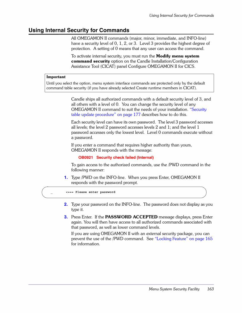
Menu System Security Facility 163
Using Internal Security for Commands
Using Internal Security for CommandsAll OMEGAMON II commands (major, minor, immediate, and INFO-line) have a security level of 0, 1, 2, or 3. Level 3 provides the highest degree of protection. A setting of 0 means that any user can access the command.
To activate internal security, you must run the Modify menu system command security option on the Candle Installation/Configuration Assistance Tool (CICAT) panel Configure OMEGAMON II for CICS.
Candle ships all authorized commands with a default security level of 3, and all others with a level of 0. You can change the security level of any OMEGAMON II command to suit the needs of your installation. “Security table update procedure” on page 177 describes how to do this.
Each security level can have its own password. The level 3 password accesses all levels; the level 2 password accesses levels 2 and 1; and the level 1 password accesses only the lowest level. Level 0 commands execute without a password.
If you enter a command that requires higher authority than yours, OMEGAMON II responds with the message:
OB0921 Security check failed (Internal)
To gain access to the authorized commands, use the /PWD command in the following manner:
1. Type /PWD on the INFO-line. When you press Enter, OMEGAMON II responds with the password prompt.
2. Type your password on the INFO-line. The password does not display as you type it.
3. Press Enter. If the PASSWORD ACCEPTED message displays, press Enter again. You will then have access to all authorized commands associated with that password, as well as lower command levels.If you are using OMEGAMON II with an external security package, you can prevent the use of the /PWD command. See “Locking Feature” on page 165 for information.
Important
Until you select the option, menu system interface commands are protected only by the default command table security (if you have already selected Create runtime members in CICAT).
_ <=== Please enter password

Using Internal Security for Commands
164 OMEGAMON II for CICS Configuration and Customization Guide Version 520
To reset the security level to 0 when you have finished doing authorized functions, press the PA1 or the ATTN key. You can also reset it by using the /PWD command in the following manner:
1. Type the /PWD command on the INFO-line and press Enter. The password prompt displays.
2. Do not enter a password; just press Enter. You will see:
Access to authorized commands will be restricted until the password is re-entered.
_________________ Password level reset

Menu System Security Facility 165
Locking Feature
Locking FeatureThe locking feature is a form of external security designed to prevent users from changing their internal security level with the /PWD command. Their level of authority is set only once and only at logon. It can be fixed to one of four levels (level 0, 1, 2, or 3).
Consider the following:
� Although the locking feature is implemented in the external security exit routine, it is designed to lock the user’s internal security level. Therefore, it affects only those commands marked as EXTERNAL=NO.
� You must define a user’s security level in CA-ACF2, RACF, or CA-TOP SECRET as an INITIALn resource, where n is a number from 0–3, and assign corresponding values to commands in the security update program (using the LEVEL keyword of the COMMAND control statement).
� The locking feature only disables the /PWD command for supplying internal passwords. /PWD can still be used for relogon to a new external userid.
� Users assigned INITIAL authority (no value of 0 to 3 attached) are allowed to change their internal security level by using /PWD.
� The locking feature starts checking INITIALn resources at the highest level. If you define INITIAL3 and INITIAL2, the user is locked to level 3.
RACF routineTo validate a user, the user exit routine checks on the RACF resource class that is defined by the ICHERCDE macro.
The resources that allow OMEGAMON II startup include INITIAL, INITIAL0, INITIAL1, INITIAL2, and INITIAL3, as shown in the following example:
The variable classnme is the resource class name you defined in “Modifying RACF and CA-ACF2 rules” on page 169.
<Allows /PWD to work>RDEFINE cccccccc INITIAL UACC(READ)
<Defines security level 0 as unaccessible>RDEFINE cccccccc INITIAL0 UACC(NONE)
<Defines security level 1 as unaccessible>RDEFINE cccccccc INITIAL1 UACC(NONE)
<Defines security level 2 as unaccessible>RDEFINE cccccccc INITIAL2 UACC(NONE)
<Defines security level 3 as unaccessible>RDEFINE cccccccc INITIAL3 UACC(NONE)
<Locks USER02 to level 2 power>PERMIT INITIAL2 CLASS(classnme) ID(USER02) ACC(READ)
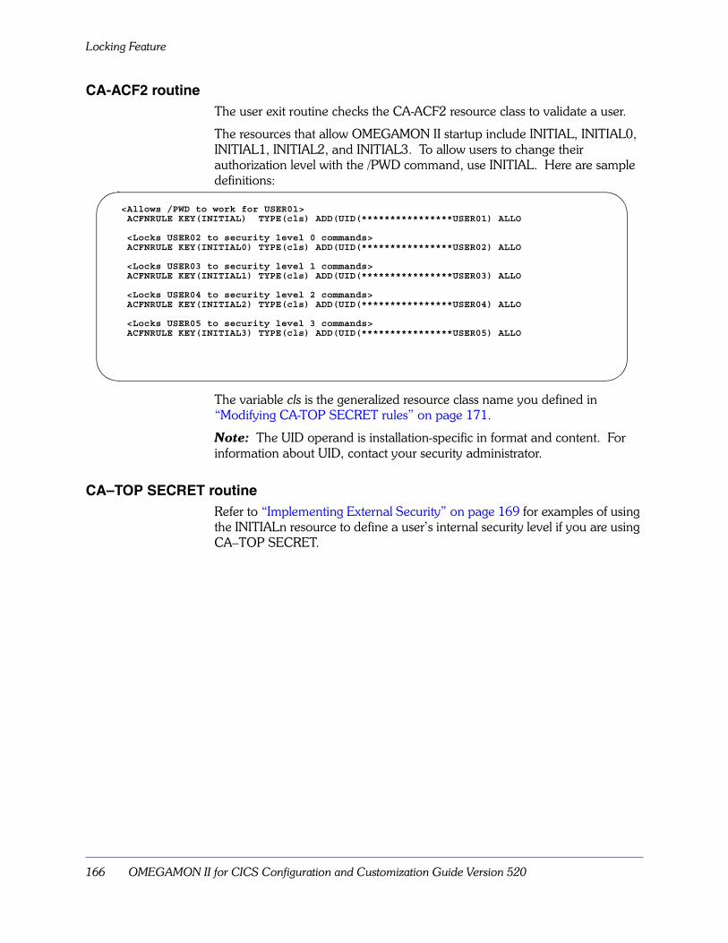
Locking Feature
166 OMEGAMON II for CICS Configuration and Customization Guide Version 520
CA-ACF2 routineThe user exit routine checks the CA-ACF2 resource class to validate a user.
The resources that allow OMEGAMON II startup include INITIAL, INITIAL0, INITIAL1, INITIAL2, and INITIAL3. To allow users to change their authorization level with the /PWD command, use INITIAL. Here are sample definitions:
The variable cls is the generalized resource class name you defined in “Modifying CA-TOP SECRET rules” on page 171.
Note: The UID operand is installation-specific in format and content. For information about UID, contact your security administrator.
CA–TOP SECRET routineRefer to “Implementing External Security” on page 169 for examples of using the INITIALn resource to define a user’s internal security level if you are using CA–TOP SECRET.
<Allows /PWD to work for USER01>ACFNRULE KEY(INITIAL) TYPE(cls) ADD(UID(****************USER01) ALLO
<Locks USER02 to security level 0 commands>ACFNRULE KEY(INITIAL0) TYPE(cls) ADD(UID(****************USER02) ALLO
<Locks USER03 to security level 1 commands>ACFNRULE KEY(INITIAL1) TYPE(cls) ADD(UID(****************USER03) ALLO
<Locks USER04 to security level 2 commands>ACFNRULE KEY(INITIAL2) TYPE(cls) ADD(UID(****************USER04) ALLO
<Locks USER05 to security level 3 commands>ACFNRULE KEY(INITIAL3) TYPE(cls) ADD(UID(****************USER05) ALLO
Menu System Security Facility 167
Using External Security
Using External SecurityOMEGAMON II supports external security for all modes of operation. For information on implementation, see “Using Internal Security for Commands” on page 163.
External security is supported for both logon and command use. When using external security, you can logon to OMEGAMON II only if they are allowed to access the “INITIAL ” resource name. A resource name of “INITIAL0”, “INITIAL1”, “INITIAL2”, or “INITIAL3” may be used to allow logon to OMEGAMON II and set the internal security level to 0, 1, 2, or 3, respectively.
When a user issues a command, OMEGAMON II performs an external security check if the following conditions are met:
� The user exit module name is specified in the security table.
� An external security exit routine is located and loaded.
� External security is specified for the issued command in the security table (using the COMMAND control statement with the EXTERNAL=YES keyword setting).
� For VTAM, ISPF, or TSO modes, the library that contains the KOBVTAM load module is APF authorized.
If any commands are specified for external security checking and an exit routine is not found, OMEGAMON II recognizes a possible security exposure and disables those commands with an internal security level of 0 for the session. Those commands with a level of 1, 2, or 3 are allowed to execute after you enter the internal password, as described in “Using Internal Security for Commands” on page 163.
Logging on using external securityThis section explains special considerations for logging on to OMEGAMON II using external security.
VTAM, TSO, or ISPF Mode logon panel
When you logon through VTAM, OMEGAMON II presents a logon panel for the OMEGAMON II VTAM application program (KOBVTAM). The VTAM logon panel also appears for ISPF and TSO modes, since OMEGAMON II uses the OMEGAMON II VTAM application program for these modes as well. The copyright screen you normally see at logon time has additional fields for USERID, PASSWORD, GROUP, and NEW PASSWORD. The advantages of using the KOBVTAM logon screen are:
� The exit routine can cause OMEGAMON II to stop an unauthorized logon.
� The exit routine makes all security checks based on the user’s logon ID and not on the OMEGAMON II address space’s authority.
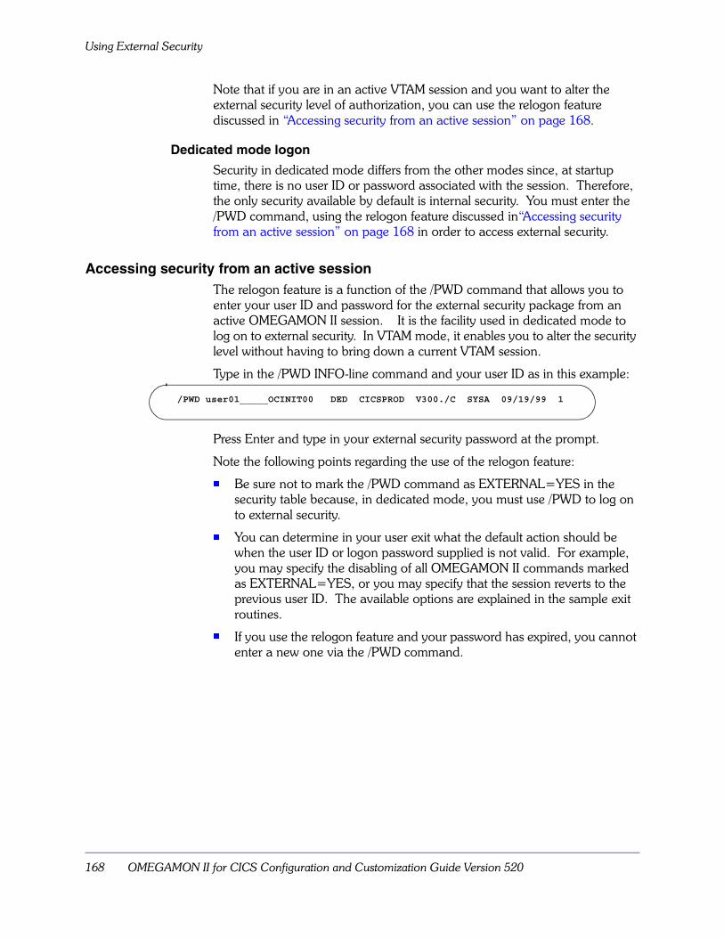
Using External Security
168 OMEGAMON II for CICS Configuration and Customization Guide Version 520
Note that if you are in an active VTAM session and you want to alter the external security level of authorization, you can use the relogon feature discussed in “Accessing security from an active session” on page 168.
Dedicated mode logon
Security in dedicated mode differs from the other modes since, at startup time, there is no user ID or password associated with the session. Therefore, the only security available by default is internal security. You must enter the /PWD command, using the relogon feature discussed in“Accessing security from an active session” on page 168 in order to access external security.
Accessing security from an active sessionThe relogon feature is a function of the /PWD command that allows you to enter your user ID and password for the external security package from an active OMEGAMON II session. It is the facility used in dedicated mode to log on to external security. In VTAM mode, it enables you to alter the security level without having to bring down a current VTAM session.
Type in the /PWD INFO-line command and your user ID as in this example:
Press Enter and type in your external security password at the prompt.
Note the following points regarding the use of the relogon feature:
� Be sure not to mark the /PWD command as EXTERNAL=YES in the security table because, in dedicated mode, you must use /PWD to log on to external security.
� You can determine in your user exit what the default action should be when the user ID or logon password supplied is not valid. For example, you may specify the disabling of all OMEGAMON II commands marked as EXTERNAL=YES, or you may specify that the session reverts to the previous user ID. The available options are explained in the sample exit routines.
� If you use the relogon feature and your password has expired, you cannot enter a new one via the /PWD command.
/PWD user01_____OCINIT00 DED CICSPROD V300./C SYSA 09/19/99 1
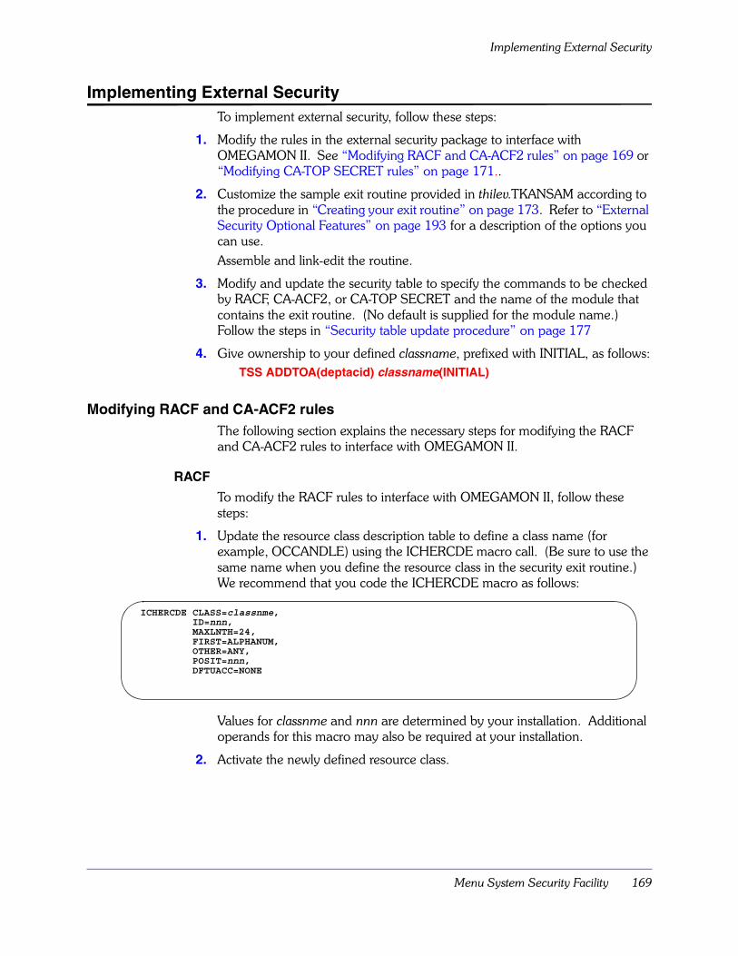
Menu System Security Facility 169
Implementing External Security
Implementing External SecurityTo implement external security, follow these steps:
1. Modify the rules in the external security package to interface with OMEGAMON II. See “Modifying RACF and CA-ACF2 rules” on page 169 or “Modifying CA-TOP SECRET rules” on page 171..
2. Customize the sample exit routine provided in thilev.TKANSAM according to the procedure in “Creating your exit routine” on page 173. Refer to “External Security Optional Features” on page 193 for a description of the options you can use.Assemble and link-edit the routine.
3. Modify and update the security table to specify the commands to be checked by RACF, CA-ACF2, or CA-TOP SECRET and the name of the module that contains the exit routine. (No default is supplied for the module name.) Follow the steps in “Security table update procedure” on page 177
4. Give ownership to your defined classname, prefixed with INITIAL, as follows:TSS ADDTOA(deptacid) classname(INITIAL)
Modifying RACF and CA-ACF2 rulesThe following section explains the necessary steps for modifying the RACF and CA-ACF2 rules to interface with OMEGAMON II.
RACF
To modify the RACF rules to interface with OMEGAMON II, follow these steps:
1. Update the resource class description table to define a class name (for example, OCCANDLE) using the ICHERCDE macro call. (Be sure to use the same name when you define the resource class in the security exit routine.) We recommend that you code the ICHERCDE macro as follows:
Values for classnme and nnn are determined by your installation. Additional operands for this macro may also be required at your installation.
2. Activate the newly defined resource class.
ICHERCDE CLASS=classnme,ID=nnn,MAXLNTH=24,FIRST=ALPHANUM,OTHER=ANY,POSIT=nnn,DFTUACC=NONE

Implementing External Security
170 OMEGAMON II for CICS Configuration and Customization Guide Version 520
3. Define a resource profile for logging on to OMEGAMON II. Use the TSO RDEFINE command with a resource of INITIAL. Here is an example of a definition that allows all users to sign onto OMEGAMON II and use the /PWD command for internal security (that is, it allows access only to those commands marked EXTERNAL=NO):
RDEFINE classnme INITIAL UACC(READ)
The variable classnme is the name assigned in step 1.
This definition is the minimum required for logon. If you want to restrict the use of the /PWD command, see“Locking Feature” on page 165.
4. Define resource profiles for the commands you wish to protect using external security (EXTERNAL=YES commands).
a. Use the TSO RDEFINE command and specify the OMEGAMON II command as the resource. Be certain to specify that only specific users may execute the command by setting UACC(NONE).
b. Use the PERMIT command to define those users who can access the resource (execute the command). Give them READ access.
The following example shows how to authorize a user to execute the PEEK command with RACF.
RDEFINE classnme PEEK UACC(NONE)
PERMIT PEEK CLASS(classnme) ID(USER01) ACCESS(READ)
Note: When you authorize commands, OMEGAMON II modifies the command name by replacing the slash of INFO-line commands with a dollar sign (/cccccc becomes $cccccc) and the period of immediate commands with @ (.cccc becomes @cccc). For example, /LOGOUT is defined to RACF as $LOGOUT in CLASS(classnme).
5. Include macro libraries in the assembly of the security exit routine. You can use SYS1.MACLIB and SYS1.AMODGEN as the macro libraries for RACF. In addition, you must include the Candle macro library, thilev.TKANMAC.
TSO/ISPF APF authorization requirements
APF authorization is required for TSO and ISPF modes to initialize with RACF. If this is not done, then an S282-10 abend will result.
CA-ACF2
To modify the CA-ACF2 rules to interface with OMEGAMON II, follow these steps:
1. If you are running OMEGAMON II in dedicated or VTAM mode, define the name of the OMEGAMON II started task to CA-ACF2.The started task name you use for OMEGAMON II in VTAM mode should have the MUSASS attribute assigned. This allows CA-ACF2 to check the individual user’s authorization rather than using the OMEGAMON II address
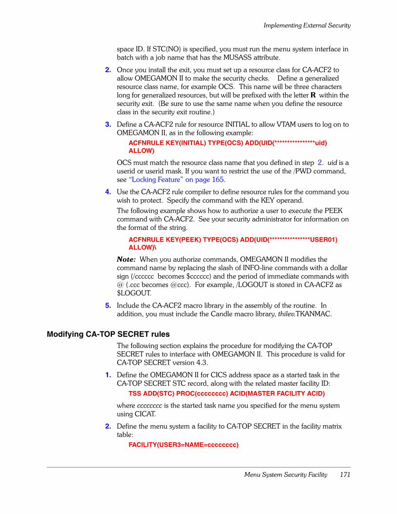
Menu System Security Facility 171
Implementing External Security
space ID. If STC(NO) is specified, you must run the menu system interface in batch with a job name that has the MUSASS attribute.
2. Once you install the exit, you must set up a resource class for CA-ACF2 to allow OMEGAMON II to make the security checks. Define a generalized resource class name, for example OCS. This name will be three characters long for generalized resources, but will be prefixed with the letter R within the security exit. (Be sure to use the same name when you define the resource class in the security exit routine.)
3. Define a CA-ACF2 rule for resource INITIAL to allow VTAM users to log on to OMEGAMON II, as in the following example:
ACFNRULE KEY(INITIAL) TYPE(OCS) ADD(UID(****************uid) ALLOW)
OCS must match the resource class name that you defined in step 2. uid is a userid or userid mask. If you want to restrict the use of the /PWD command, see “Locking Feature” on page 165.
4. Use the CA-ACF2 rule compiler to define resource rules for the command you wish to protect. Specify the command with the KEY operand. The following example shows how to authorize a user to execute the PEEK command with CA-ACF2. See your security administrator for information on the format of the string.
ACFNRULE KEY(PEEK) TYPE(OCS) ADD(UID(****************USER01) ALLOW)\
Note: When you authorize commands, OMEGAMON II modifies the command name by replacing the slash of INFO-line commands with a dollar sign (/cccccc becomes $cccccc) and the period of immediate commands with @ (.ccc becomes @ccc). For example, /LOGOUT is stored in CA-ACF2 as $LOGOUT.
5. Include the CA-ACF2 macro library in the assembly of the routine. In addition, you must include the Candle macro library, thilev.TKANMAC.
Modifying CA-TOP SECRET rulesThe following section explains the procedure for modifying the CA-TOP SECRET rules to interface with OMEGAMON II. This procedure is valid for CA-TOP SECRET version 4.3.
1. Define the OMEGAMON II for CICS address space as a started task in the CA-TOP SECRET STC record, along with the related master facility ID:
TSS ADD(STC) PROC(cccccccc) ACID(MASTER FACILITY ACID)
where cccccccc is the started task name you specified for the menu system using CICAT.
2. Define the menu system a facility to CA-TOP SECRET in the facility matrix table:
FACILITY(USER3=NAME=cccccccc)

Implementing External Security
172 OMEGAMON II for CICS Configuration and Customization Guide Version 520
FACILITY(cccccccc=MODE=FAIL,ACTIVE.SHRPRF)
FACILITY(cccccccc=PGM=KOB,NOASUBM,NOABEND,NOXDEF)
FACILITY(cccccccc=ID=3,MULTIUSER,RES,WARNPW,SIGN(M))
FACILITY(cccccccc=NOINSTDATA,NORNDPW,AUTHINIT,NOPROMPT,NOAUDIT)
FACILITY(cccccccc=NOTSOC,NOMRO,LOG(INIT,SMF,MSG,SEC9))
where cccccccc is the started task name you specified for the menu system using CICAT.
3. Define the menu system facility to users:TSS ADD(ACID) FACILITY(cccccccc)
where cccccccc is the started task name you specified for the menu system using CICAT.
4. Define a Resource Descriptor Table entry:TSS ADD(RDT) RESCLASS(OCCANDLE) RESCODE(XX)
OCCANDLE is defined in the KOCATOPS program. If you change it in the KOCATOPS module, be sure to also change it here. The rescode is a hexadecimal value of 01–3f.
5. To permit access to the OMEGAMON II command level, enter the following:TSS PERMIT(userid) OCCANDLE (INITIAL0)
TSS PERMIT(userid) OCCANDLE (INITIAL1)
TSS PERMIT(userid) OCCANDLE (INITIAL2)
TSS PERMIT(userid) OCCANDLE (INITIAL3)
TSS PERMIT(userid) OCCANDLE (‘INITIAL ‘)
Every user must have access to at least one of the above resources. The last permit allows a user to change command level if the password is known to that user. The first four permits lock a user into the particular command level.
6. Enter the following to enable CA-TOP SECRET to validate commands:TSS PERMIT(userid) OCCANDLE(XXXX)
where xxxx is an OMEGAMON II command that has been defined with EXTERNAL=YES in the OMEGAMON II command table.
If you use CA-TOP SECRET to define an initial access to OMEGAMON II, you should specify EXTERNAL=NO in the control statements.
7. You must also specify the CA-TOP SECRET interface module KOCATOPSto enable the CA-TOP SECRET interface.
Use the TSS PERMIT command to define those users who can access the resource by executing the OMEGAMON II command.
The following example shows how to authorize a user to execute the PEEK command with CA-TOP SECRET.

Menu System Security Facility 173
Implementing External Security
TSS PERMIT(userid) cccccccc(PEEK)
The variable cccccccc is the resource class name you define for CA-TOP SECRET.
Note: When you authorize commands, OMEGAMON II modifies the command name by replacing the slash of INFO-line commands with a dollar sign (/cccccc becomes $cccccc) and the period of immediate commands with @ (.cccc becomes @cccc). For example, /LOGOUT is defined to CA-TOP SECRET as $LOGOUT in CLASS(classnme).
Creating your exit routineThe exit routine provides an interface between OMEGAMON II and the security product. You can specify any unique name for your routine, but that name must also be specified in the control statements that update the security table. For more information, see the MODULE= parameter under “Control statements” on page 179. The exit routine can be shared between systems.
The KOCARACF, KOCAACF2, and KOCATOPS members of thilev.TKANSAM contain models of RACF, CA-ACF2, and CA-TOP SECRET routines. Many installations use these members without modification, but since security procedures are installation-dependent, they have been documented with comments to enable you to modify them. They are supplied as examples only.
Note: Be sure that the resource class you define in the exit routine has the same name as the resource class you defined when modifying RACF, CA-ACF2, or CA-TOP SECRET rules.
The thilev.TKANSAM dataset contains members called KOCJACF2, KOCJRACF, and KOCJTOPS, which supply sample JCL to help you assemble and link-edit your routine.
You can use the same exit routine to define security for multiple OMEGAMON IIs. Use the same name on the MODULE= statement for each OMEGAMON II (see “MODULE control statement” on page 183). You could use the value of the B#DDPRFX field in the $BIA data area as part of a resource name to be used for the OMEGAMON II currently in use.
If you have a security system other than RACF or CA-ACF2, you can still implement a security interface using these models. Use the sample RACF and CA-ACF2 exits as guides to see what information is passed to the exit routine and what information is returned to OMEGAMON II.
OMEGAMON II calling conventions
OMEGAMON II uses a single control block $UCHECK, to pass information to the exit routine. The exit routine also uses $UCHECK to pass information back to OMEGAMON II. The $UCHECK control block is mapped by the $UCHECK macro. The macro is defined in member KOBGMAC of thilev.TKANMAC.

Implementing External Security
174 OMEGAMON II for CICS Configuration and Customization Guide Version 520
The U#CHPIA field in $UCHECK points to the address of a 16-byte control block. The KOCPIA macro, defined in thilev.TKANMAC, maps this control block and gives you the CICS jobname the user requested at logon. OMEGAMON II maintains the control block for the entire life of the session, and gives the installation a 512-byte work area for its own use.
The user exit module is called by OMEGAMON II with the following conventions:
Important
The $UCHECK work area is limited to 512 bytes. If your installation requires a larger work area, GETMAIN the additional storage required and place the pointer to this GETMAINed area in $UCHECK. An attempt to enlarge this work area beyond its 512-byte limit in any other way causes an overlay of essential OMEGAMON II control blocks, and results are unpredictable. If you modify the RACF RACROUTE macro, you must GETMAIN at least 512 bytes for use as the WORKA work area.
Register 1 Address of parameter list.
Register 13 Address of a standard save area.
Register 14 Return address.
Register 15 Entry point address (in).
Register 15 Return code (out).
Parameter list:
Word 1 Address of control block.

Menu System Security Facility 175
Implementing External Security
OMEGAMON II calling flow
The following procedure describes the flow for calls from OMEGAMON II to your user security exit routine at initialization, during command verification, and at termination.
1. At initialization, when OMEGAMON II passes control to your user exit routine, the initialization call is indicated by an I in the U#CHTYP field. This indicates that OMEGAMON II requires a logon validation.
a. If the user ID field length is non-zero, the user ID and password information are available.
b. If additional information or some form of retry is required, the routine can request a reshow of the screen, and reset any field lengths to indicate that no data is present (user ID, password, group, or new password).
To perform a reshow in VTAM mode,
� set a message into the U#CHMSG field (120 bytes maximum length)
� set the U@CHRSHO bit in U#CHRESP
� return to the caller.
The message appears below the panel. Appropriate fields are filled in (original user ID and password), unless overridden (length = 0).
c. When validation is complete, a return code of 0 from the user exit indicates that the user should be allowed to log on. Any other return code will cause the session to be aborted.
d. Upon successful logon acceptance, the validation routine may perform resource validation and optionally assign a command security level (0, 1, 2, or 3) to the user. The default is 0. Place the appropriate number into U#CHAUT4. To force the user to use only this level, also set the U@CH1LOK bit in U#CHAUT1.
2. During command verification, OMEGAMON II places a C in the U#CHTYP field. At this point, the user’s authorization can be checked. The decision to allow or disallow a command on the first encounter cannot be changed on subsequent tries by the same user unless security is reset with the /PWD command. However, on each try, the user exit is notified, an audit record may be written, and a customized error message may be issued.Return codes from the exit routine may be:
RC = 0 Indicates that the command is allowed (RACF and CA-ACF2).
RC = 4 Indicates that the command is unknown to RACF (RACF only). OMEGAMON II will allow the command to execute. See “Modifying RACF and CA-ACF2 rules” on page 169 for instructions to define a command to RACF.
RC = 8 Indicates that the command is known to the security package and access is denied (RACF and CA-ACF2).

Implementing External Security
176 OMEGAMON II for CICS Configuration and Customization Guide Version 520
When you authorize commands, OMEGAMON II modifies the command name by replacing the slash of INFO-line commands with a dollar sign (/cccccc becomes $cccccc), and the period of immediate commands with @ (.ccc becomes @ccc).
3. At relogon, OMEGAMON II places an R in the U#CHTYP field to indicate a logon validation. The processing is the same as at initialization time, except that users may not enter a new password or group because OMEGAMON II does not display a logon panel.
4. At termination, OMEGAMON II passes a T to the user’s exit routine. You can then do any termination cleanup required, such as freeing user control blocks and FREEMAINing any GETMAINed areas.

Menu System Security Facility 177
Modifying the Security Table
Modifying the Security TableThis section describes how to update the security table for both external and internal security. The following is a summary of the available options.
Security table update procedureTo update the security table, use CICAT to:
1. Access the Modify menu system command security option on the CICAT Configure OMEGAMON II for CICS panel.
The rules and keywords for the control statements are described in “Control statements” on page 179.
Table 30. Security Control Statements
Control Statement Description
AUTHLIB Specifies an authorized screen space (PROC) library for initialization that bypasses the security check.
COMMAND Sets the internal security levels of commands, marks them for external security, and requests an audit.
LIST Specifies whether a listing of the current security settings is to be produced on this run.
MINOR Specifies the security options for minor commands.
MODULE Specifies the name of the module containing the user’s external security exit routine.
PASSWORD Specifies the internal passwords.
RESET Clears current settings.
SMFNUM Specifies the record number for SMF audit requests.
UPDATE Specifies whether updating is to be performed on this run.
Important
To change an existing setting for a parameter, you must specify a new setting rather than just blanking out the old setting. For example, to remove a command from external security checking, change EXTERNAL=YES to EXTERNAL=NO.
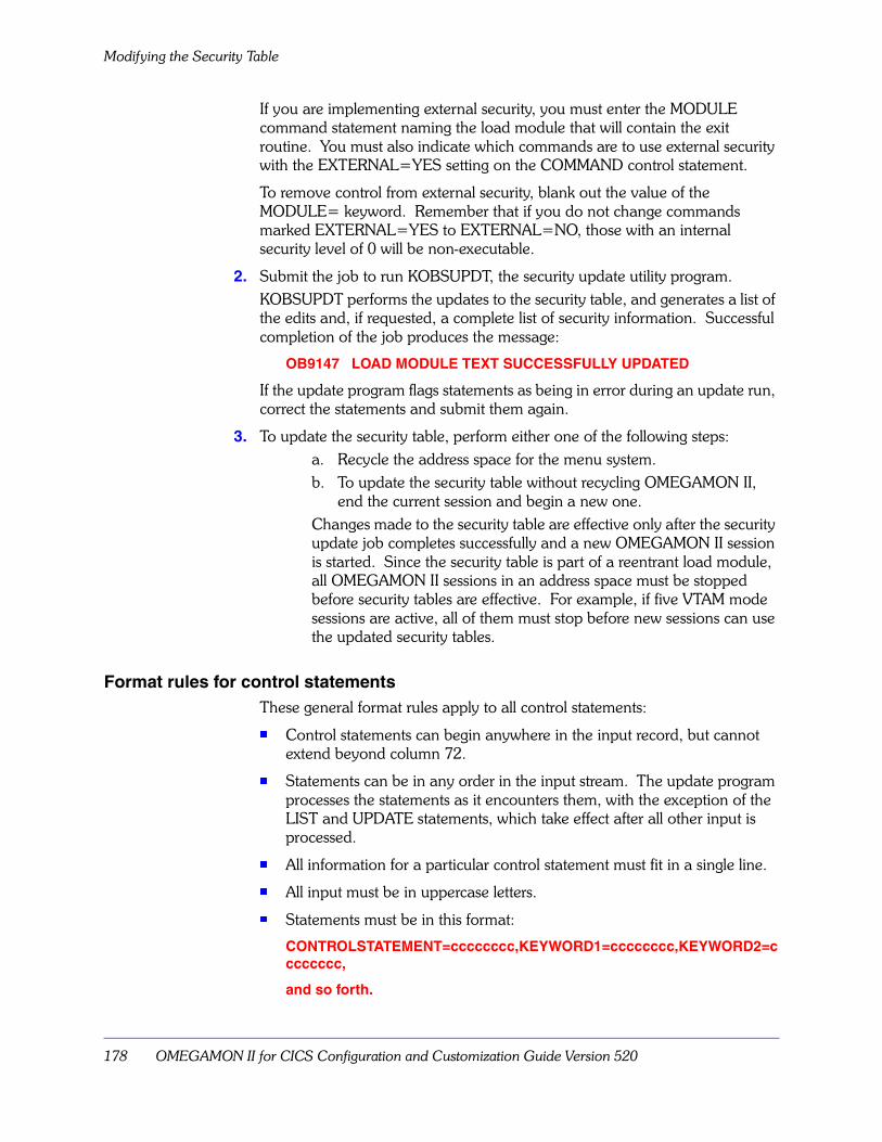
Modifying the Security Table
178 OMEGAMON II for CICS Configuration and Customization Guide Version 520
If you are implementing external security, you must enter the MODULE command statement naming the load module that will contain the exit routine. You must also indicate which commands are to use external security with the EXTERNAL=YES setting on the COMMAND control statement.
To remove control from external security, blank out the value of the MODULE= keyword. Remember that if you do not change commands marked EXTERNAL=YES to EXTERNAL=NO, those with an internal security level of 0 will be non-executable.
2. Submit the job to run KOBSUPDT, the security update utility program.KOBSUPDT performs the updates to the security table, and generates a list of the edits and, if requested, a complete list of security information. Successful completion of the job produces the message:
OB9147 LOAD MODULE TEXT SUCCESSFULLY UPDATED
If the update program flags statements as being in error during an update run, correct the statements and submit them again.
3. To update the security table, perform either one of the following steps:a. Recycle the address space for the menu system.b. To update the security table without recycling OMEGAMON II,
end the current session and begin a new one.Changes made to the security table are effective only after the security update job completes successfully and a new OMEGAMON II session is started. Since the security table is part of a reentrant load module, all OMEGAMON II sessions in an address space must be stopped before security tables are effective. For example, if five VTAM mode sessions are active, all of them must stop before new sessions can use the updated security tables.
Format rules for control statementsThese general format rules apply to all control statements:
� Control statements can begin anywhere in the input record, but cannot extend beyond column 72.
� Statements can be in any order in the input stream. The update program processes the statements as it encounters them, with the exception of the LIST and UPDATE statements, which take effect after all other input is processed.
� All information for a particular control statement must fit in a single line.
� All input must be in uppercase letters.
� Statements must be in this format:
CONTROLSTATEMENT=cccccccc,KEYWORD1=cccccccc,KEYWORD2=cccccccc,
and so forth.

Menu System Security Facility 179
Modifying the Security Table
There can be no intervening blanks. The update program treats data that follows a blank as a comment. The data prints on the edit listing, but is ignored for processing purposes.
� To insert comment lines anywhere in the input stream, place an asterisk (*) in column 1 of the input record.
� If the update program flags statements as being in error, correct the statements and submit them again. To change a setting, you must specify a new setting rather than blank out the old setting. This is especially important to remember when changing a command from EXTERNAL=YES to EXTERNAL=NO.
� OMEGAMON II does not recognize changes to control statements until the update job successfully terminates and a new OMEGAMON II session is started. The control statement edit listing should indicate successful completion of the update.
Control statementsFollowing are the control statements and their keywords. Keyword defaults are underscored.
AUTHLIB control statement
This control statement specifies the dataset name of an authorized screen space library that contains commands to invoke at OMEGAMON II initialization, bypassing any security checks. This option lets you execute protected commands as part of the initialization screen without entering a password.
Since all security checking for screens coming from the AUTHLIB dataset is bypassed, WRITE access to this dataset should be restricted.
Security checking resumes when any of the following occurs:
� OMEGAMON II fetches a screen from an unauthorized library
� OMEGAMON II fetches a screen that has been loaded into memory
� you enter any keystroke, including a cursor movement
Important
If you create an authorized screen library and use the OMEGAMON II menu system, security checking will cause initialization to fail when:� OMEGAMON II fetches a screen containing an authorized command. Menu system users
should leave the .FGO and .VAR commands unprotected.� OMEGAMON II fetches a screen space that has been loaded into memory. @ZSCRNDF is the
screen that loads screen spaces into memory.

Modifying the Security Table
180 OMEGAMON II for CICS Configuration and Customization Guide Version 520
The format of the AUTHLIB control statement is as follows:
where dsname is the name of the authorized screen library you have created.
AUTHLIB accepts the following keyword:
Concatenate the dataset containing the authorized screens in your RKOCPROC DD statement.
Note: Do not APF-authorize the dataset that contains the authorized screens.
COMMAND control statement
This control statement specifies the name of an OMEGAMON II major, immediate, or INFO-line command to be protected. Minor commands are protected at the major command level unless the MINOR control statement is specified.
When you update an INFO-line command, you must use the actual command name and not its alias. OMEGAMON II automatically assigns the same protection attributes to all aliases of the command.
OMEGAMON II does not check for multiple COMMAND statements for the same command in the same run. The last COMMAND statement for the command is the one that OMEGAMON II processes.
The format of the COMMAND control statement is as follows:
where cccc, .ccc, or /cccccc is the name of the OMEGAMON II command to be protected.
To have the control statement edit listing show the current security settings for a command, enter a COMMAND=cccc, =.ccc, or =/cccccc statement with no additional operands.
VOL Specifies the volume serial where the specified dataset resides. This acts as an additional security measure. You must specify a volume serial number even if the dataset is cataloged.
The AUTHLIB statement always requires the VOL keyword. If you do not want the additional volume serial number checking to be performed, specify NOVOLUME.
AUTHLIB=dsname,VOL={volume|NOVOLUME}
COMMAND={cccc|.ccc|/cccccc}[,LEVEL={0|2|3|DISABLE}][,EXTERNAL={YES|NO}][,AUDIT={WTO|SMF|BOTH|NONE}]

Menu System Security Facility 181
Modifying the Security Table
COMMAND accepts the following keywords:
LEVEL Specifies the internal security level to be associated with this command.� Level 0 allows the command to execute without an internal
security check� Levels 1, 2, and 3 specify that the command executes only if
you have previously entered the corresponding password for that level (or for a higher level) via the /PWD INFO-line command.
� DISABLE specifies that OMEGAMON II is never to execute the command.
You can audit attempts to execute the command for the session, but you cannot specify internal or external security.
EXTERNAL Specifies whether an external security package checks this command.
OMEGAMON II ignores the EXTERNAL keyword if you specify LEVEL=DISABLE.
If you code EXTERNAL=YES for a command and no exit routine is available, OMEGAMON II disables the command for the session if it has an associated security level of 0, or defaults to internal security if the command has a security level of 1, 2, or 3.
Once you specify EXTERNAL=YES, you can change it only if you specify EXTERNAL=NO and rerun the security update program.
AUDIT Specifies whether OMEGAMON II is to audit the command each time a user invokes it. The possible values are:
WTO Produces a one-line message on the master console.
SMF Specifies that OMEGAMON II write an SMF record. The SMF record number must be specified in the SMFNUM control statement. If the SMF audit cannot be performed, OMEGAMON II defaults to a WTO audit.
See“Creating the SMF Audit” on page 192 for details about setting up the SMF audit. This option requires APF authorization.
BOTH Specifies that OMEGAMON II issue a WTO message to a console and write an SMF record.
NONE Specifies no auditing. This is the default setting.
If you specify an audit for a disabled command, you are notified of attempts to execute it.

Modifying the Security Table
182 OMEGAMON II for CICS Configuration and Customization Guide Version 520
LIST control statement
This control statement specifies whether the update program produces a security file listing. A security file listing is a complete record of the security table that shows the name of the authorized screen library, its volume serial number, the name of the user exit module, and all command names along with their corresponding security information. It does not list the internal security passwords.
If you also specify UPDATE=NO, the listing shows what the control statements and security information would look like if the update had taken place.
To generate the security file listing independent of edits to the control statements, you may submit LIST=YES as the only control statement in the input stream.
Only one LIST statement is allowed per run. The default is LIST=NO.
The format of the LIST control statement is as follows:
MINOR control statement
This control statement specifies the name of an OMEGAMON II minor command to protect. OMEGAMON IIprotects the minor commands independent of the majors. Therefore, any changes to minor commands apply to all minors with the same name and attributes, regardless of their major commands.
Access to a minor command requires access to the appropriate major command. If you do not specify an EXTERNAL keyword, the associated major controls access to this minor command.
No check is made for multiple MINOR statements for the same minor command in the same run. The last MINOR statement for the minor takes effect.
The format of the MINOR control statement is as follows:
where ccccis the name of the minor command to be protected.
Refer to the COMMAND control statement for explanations of the keywords.
LIST={YES|NO}
MINOR=cccc[,LEVEL={1|2|3|DISABLE}][,EXTERNAL={YES|NO}][,AUDIT={WTO|SMF|BOTH|NONE}]
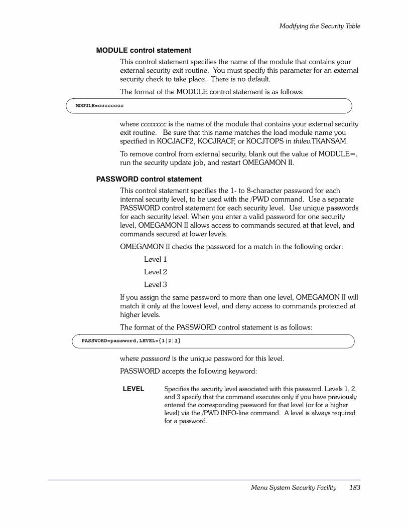
Menu System Security Facility 183
Modifying the Security Table
MODULE control statement
This control statement specifies the name of the module that contains your external security exit routine. You must specify this parameter for an external security check to take place. There is no default.
The format of the MODULE control statement is as follows:
where cccccccc is the name of the module that contains your external security exit routine. Be sure that this name matches the load module name you specified in KOCJACF2, KOCJRACF, or KOCJTOPS in thilev.TKANSAM.
To remove control from external security, blank out the value of MODULE=, run the security update job, and restart OMEGAMON II.
PASSWORD control statement
This control statement specifies the 1- to 8-character password for each internal security level, to be used with the /PWD command. Use a separate PASSWORD control statement for each security level. Use unique passwords for each security level. When you enter a valid password for one security level, OMEGAMON II allows access to commands secured at that level, and commands secured at lower levels.
OMEGAMON II checks the password for a match in the following order:
Level 1
Level 2
Level 3
If you assign the same password to more than one level, OMEGAMON II will match it only at the lowest level, and deny access to commands protected at higher levels.
The format of the PASSWORD control statement is as follows:
where password is the unique password for this level.
PASSWORD accepts the following keyword:
LEVEL Specifies the security level associated with this password. Levels 1, 2, and 3 specify that the command executes only if you have previously entered the corresponding password for that level (or for a higher level) via the /PWD INFO-line command. A level is always required for a password.
MODULE=cccccccc
PASSWORD=password,LEVEL={1|2|3}

Modifying the Security Table
184 OMEGAMON II for CICS Configuration and Customization Guide Version 520
RESET control statement
This control statement clears the current settings of the other control statements. Reset commands remain unprotected unless you specify new settings with the appropriate control statements and rerun the update program.
Only one RESET statement is allowed per run.
The format of the RESET control statement is as follows:
where cccccccc is one of the following arguments:
SMFNUM control statement
This control statement indicates the ID number of the SMF record that OMEGAMON II should use for its audit.
The format of the SMFNUM control statement is as follows:
where nnn is the SMF record ID number. This ID number assigned to OMEGAMON II audit must be from 128 through 255, and should be different from that used by any other application. There is no default.
ALL Clears settings for all control statements and all keywords in the OMEGAMON II security table.
AUTHLIB Clears the name and volume serial number of the authorized screen library.
INFO Clears settings for all INFO-line commands (on the COMMAND control statement). For example, if you do not want to use the Candle Corporation default security levels for INFO-line commands and want to start over, enter RESET=INFO. For INFO-line commands, this resets all LEVEL settings to security level 0 and also clears any existing EXTERNAL and AUDIT settings.
MAJOR Clears settings for all major and immediate commands (on the COMMAND control statement). See INFO above for an example.
MINOR Clears settings for all minor commands.
MODULE Clears the name of the user’s exit routine module.
PASSWORD Clears the internal passwords.
SLASH Same as INFO.
SMFNUM Clears the record number for SMF audits.
YES Same as ALL.
RESET=cccccccc
SMFNUM=nnn
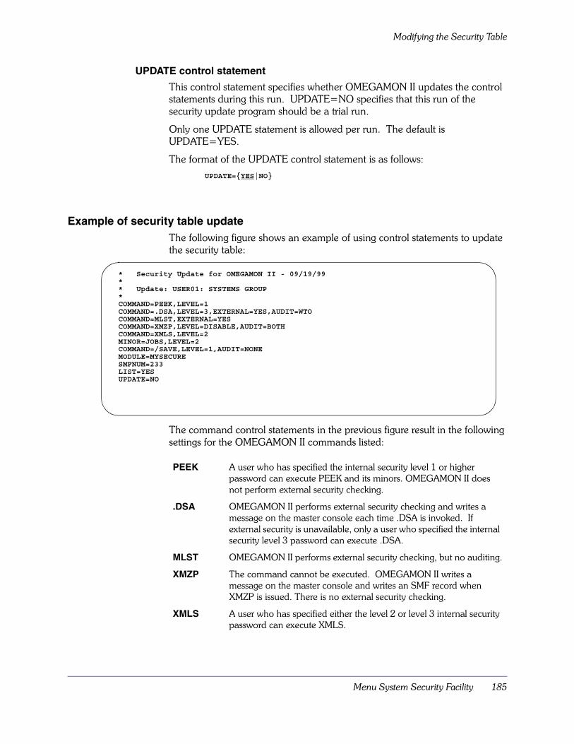
Menu System Security Facility 185
Modifying the Security Table
UPDATE control statement
This control statement specifies whether OMEGAMON II updates the control statements during this run. UPDATE=NO specifies that this run of the security update program should be a trial run.
Only one UPDATE statement is allowed per run. The default is UPDATE=YES.
The format of the UPDATE control statement is as follows:
Example of security table updateThe following figure shows an example of using control statements to update the security table:
The command control statements in the previous figure result in the following settings for the OMEGAMON II commands listed:
PEEK A user who has specified the internal security level 1 or higher password can execute PEEK and its minors. OMEGAMON II does not perform external security checking.
.DSA OMEGAMON II performs external security checking and writes a message on the master console each time .DSA is invoked. If external security is unavailable, only a user who specified the internal security level 3 password can execute .DSA.
MLST OMEGAMON II performs external security checking, but no auditing.
XMZP The command cannot be executed. OMEGAMON II writes a message on the master console and writes an SMF record when XMZP is issued. There is no external security checking.
XMLS A user who has specified either the level 2 or level 3 internal security password can execute XMLS.
UPDATE={YES|NO}
* Security Update for OMEGAMON II - 09/19/99** Update: USER01: SYSTEMS GROUP*COMMAND=PEEK,LEVEL=1COMMAND=.DSA,LEVEL=3,EXTERNAL=YES,AUDIT=WTOCOMMAND=MLST,EXTERNAL=YESCOMMAND=XMZP,LEVEL=DISABLE,AUDIT=BOTHCOMMAND=XMLS,LEVEL=2MINOR=JOBS,LEVEL=2COMMAND=/SAVE,LEVEL=1,AUDIT=NONEMODULE=MYSECURESMFNUM=233LIST=YESUPDATE=NO

Modifying the Security Table
186 OMEGAMON II for CICS Configuration and Customization Guide Version 520
The remaining control statements result in the following settings.
JOBS JOBS is a minor of the PEEK command which was specified above as a level 1 authorized command; however, the LEVEL=2 setting on JOBS specifies that only level 2 or 3 users can access it.
/SAVE A user who has specified either the level 1, level 2, or level 3 password can execute the /SAVE command. It is not audited.
MODULE MYSECURE is the name of the module that contains the security exit routine.
SMFNUM The SMF ID is set as 233.
LIST YES indicates that OMEGAMON II produces a listing.
UPDATE NO indicates that OMEGAMON II does not update the security table. This is a trial run.

Menu System Security Facility 187
Security Update Program Listing
Security Update Program ListingThe security update program generates a listing of the control statement modifications that have been made. With the LIST control statement, you have the option of producing an additional listing that includes all of the security information.
The security update program listing consists of four parts:
� header
� control statement edit listing
� security file listing
� security update program trace
The header contains the following information:
� the name of the dataset where the load module resides
� the name of the module that contains the security table (KOCCMX00)
� the OMEGAMON II version number in the format VnnnCOM
� messages indicating successful completion of the job or error conditions, such as a failure to open the SYSLIB dataset or read the security table
The following figure shows a typical header:
OBSECUP 1.2--OMEGAMON II SECURITY UPDATE PROGRAM--(c) CANDLE CORPORATION--
OB9261 OBSECUP BEGUNOB9144 OBSELR00 CALLED TO READ KOCCMX00OB9148 SYSLIB DCB OPENED SUCCESSFULLYOB9149 LIBRARY DSNAME IS: CANDLE.RKANMODOB9158 LOAD MODULE ID:
OMCMDEXV500COM09/19/99 19:02
OB9146 LOAD MODULE TEXT SUCCESSFULLY READOB9150 SYSLIB DCB CLOSEDOB9262 LOAD MODULE READ RETURN CODE IS 0000

Security Update Program Listing
188 OMEGAMON II for CICS Configuration and Customization Guide Version 520
Control statement edit listingThe update report contains a listing of the control statements that have been edited. The listing shows the previous contents (except for previous passwords), as well as the new contents.
If you specified UPDATE=YES, OMEGAMON II reports the date and time of the previous update.
The following figure shows a typical listing.
FIGURE 12. Typical Control Statement Edit Listing
OBSECUP 1.2--OMEGAMON II SECURITY UPDATE PROGRAM--(c) CANDLE CORPORATION--
*** CONTROL STATEMENT EDIT ***
AUTHLIB=rhilev.RKOCPROC,VOL=NOVOLUMEPREVIOUS CONTENTS =NEW CONTENTS = rhilev.RKOCPROC NOVOLUME
* CHANGE THE PASSWORD FOR LEVEL 3 COMMAND ACCESSPASSWORD=CANDLE3,LEVEL=3
PREVIOUS CONTENTS = ******** NEW CONTENTS = CANDLE3
* DISPLAY SECURITY INFORMATION FOR THE PEEK COMMANDCOMMAND=PEEK
PREVIOUS CONTENTS = 3 B NEW CONTENTS = 3 B
* DISPLAY SECURITY INFORMATION FOR MINOR JOBSMINOR=JOBS
PREVIOUS CONTENTS = 0EW NEW CONTENTS = 0EW
* PROTECT MZAP COMMANDCOMMAND=MZAP,LEVEL=3
PREVIOUS CONTENTS = 0 NEW CONTENTS = 3
* DISABLE CONS COMMANDCOMMAND=CONS,LEVEL=DISABLE,AUDIT=BOTH
PREVIOUS CONTENTS = 0 NEW CONTENTS = * B
*** END OF CONTROL STATEMENT INPUT ***

Menu System Security Facility 189
Security Update Program Listing
The codes for the PREVIOUS CONTENTS and NEW CONTENTS of commands are positional. There are three positions:
1. The first position shows the number of the internal security level or an asterisk (*) if the command has been DISABLED.
2. The second position shows the external security option:
3. The third position shows the auditing option:
E Use external security for this command.
b Blank specifies no external security.
W Audit this command via WTO.
S Audit this command via SMF.
B Audit this command via WTO and SMF.
b Blank indicates no auditing.
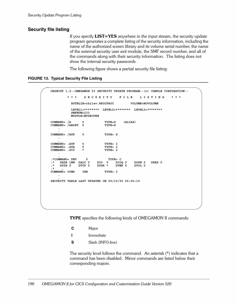
Security Update Program Listing
190 OMEGAMON II for CICS Configuration and Customization Guide Version 520
Security file listingIf you specify LIST=YES anywhere in the input stream, the security update program generates a complete listing of the security information, including the name of the authorized screen library and its volume serial number, the name of the external security user exit module, the SMF record number, and all of the commands along with their security information. The listing does not show the internal security passwords.
The following figure shows a partial security file listing:
FIGURE 13. Typical Security File Listing
TYPE specifies the following kinds of OMEGAMON II commands:
The security level follows the command. An asterisk (*) indicates that a command has been disabled. Minor commands are listed below their corresponding majors.
C Major
I Immediate
S Slash (INFO-line)
OBSECUP 1.2--OMEGAMON II SECURITY UPDATE PROGRAM--(c) CANDLE CORPORATION--
* * * S E C U R I T Y F I L E L I S T I N G * * *
AUTHLIB=rhilev.RKOCPROC VOLUME=NOVOLUME
LEVEL1=******** LEVEL2=******** LEVEL3=********SMFNUM=233MODULE=MYSECURE
COMMAND= /A 0 TYPE=S (ALIAS)COMMAND= /ABORT 0 TYPE=S
.
.COMMAND= /AUP 0 TYPE= S
.
.COMMAND= .AUP 0 TYPE= ICOMMAND= .DSA 0 TYPE= ICOMMAND= .SCC * TYPE= I
.
..*COMMAND= DEV 0 TYPE= C.* DADR 1EW DALC 0 DIO 0 DIOQ 0 DOPN 0 DRES 0.* DSTA 0 DTYP 0 DUSR * DVMP 0 DVOL 0.* .COMMAND= OCMD 3EB TYPE= I
.
.SECURITY TABLE LAST UPDATED ON 09/19/99 06:00:10

Menu System Security Facility 191
Security Update Program Listing
Security update program traceThe last part of the listing indicates whether an update has successfully completed.
The following figure shows a typical trace:
FIGURE 14. Typical Security Update Program Trace
OBSECUP 1.2--OMEGAMON II SECURITY UPDATE PROGRAM--(c) CANDLE CORPORATION--
OB9145 OBSELW00 CALLED TO WRITE cccccccc.OB9148 SYSLIB DCB CLOSED SUCCESSFULLYOB9147 LOAD MODULE TEXT SUCCESSFULLY UPDATEDOB9150 SYSLIB DCB CLOSEDOB9269 OBSECUP ENDED
Creating the SMF Audit
192 OMEGAMON II for CICS Configuration and Customization Guide Version 520
Creating the SMF AuditWhen creating the SMF audit, make sure that the SMF Record Exits (IEFU83 and IEFU84) and the SMF system parameters specifications (SMFPRMcc) do not suppress OMEGAMON II’s ability to journal the audit activity records.
The SMF record consists of:
� The IBM header (mapped by IFASMFR).
� The Candle Corporation Common Header (mapped by $CANHDR, which is defined in member KOBGMAC of thilev.TKANMAC).
� The security audit record (mapped by $AUDIT, which is defined in member KOBGMAC of thilev.TKANMAC).
The audit record contains:
� Date/time/system stamp.
� User ID/jobname associated with the session.
� Actual command text as it was entered on the OMEGAMON II screen. Records of minor commands also reference their associated major commands.
Use the SMF audit selectively. Because the overhead for producing SMF records is high, use it only with sensitive commands, such as those that could disrupt the system (for example, OCMD and MZAP).
The KOBSMFRP member of the thilev.TKANSAM dataset contains a sample SMF post-processor and report generator in source code format. This is supplied as an example only.

Menu System Security Facility 193
External Security Optional Features
External Security Optional FeaturesYou can set up your user exit routine (as explained in “Creating your exit routine” on page 173) to use any of the options discussed in this section. Remember that you can also use the control options supplied with the security package, such as SHIFT validation and SOURCE validation, by marking the commands EXTERNAL=YES and implementing the option as the security package directs.
Custom error messagesTo suit your individual requirements, your installation can create custom error messages to display when a user has insufficient authority, or enters an invalid user ID or password. See the sample exit routines in the members KOCARACF, KOCAACF2, and KOCATOPS in the thilev.TKANSAM dataset for information about how to do this. The user security message may be up to 120 bytes long, except for INFO-line messages (for example, /PWD relogon messages), which may be a maximum of 60 bytes.
Password updateYou can give the user the capability of interactive communication when logging on to external security. For example, if a user logs on with an expired password, the security exit may prompt the user for a new password and update the security database. This capability is not available when relogging on with the /PWD command.
Audit suppressionOMEGAMON II gives you the flexibility of suppressing WTO or SMF auditing. At initialization or relogon, your exit routine may set a flag in $UCHECK to indicate WTO or SMF suppression.
Supplemental auditingIn addition to the WTO and SMF audits available with OMEGAMON II, you can use the audit features of the external security package to supplement command tracking. The RACF Report Writer and CA-ACF2 ACFRPT utility programs are examples of this supplemental audit capability.

External Security Optional Features
194 OMEGAMON II for CICS Configuration and Customization Guide Version 520
SMF Considerations 195
SMF Considerations
Chapter OverviewOMEGAMON II writes interval, system-related, and task-related records to the IBM System Management Facility (SMF). You can use these records to produce historical reports of your system’s performance. This chapter describes these records and the ways to start, stop, and limit their logging on to SMF.
You specify all the options for SMF logging using the Global Data Area. For more informations, refer to“Specifying the Monitoring Options for the Product” on page 79.
Depending on the options you specified in your Global Data Area for collecting data, OMEGAMON II can write many records per second to SMF. Therefore, make sure your site has enough storage in your SMF datasets for these records.
This chapter covers the operational considerations when logging to SMF. For more information about the OMEGAMON II features that use SMF, refer to the OMEGAMON II for CICS Reference Manual.
Chapter ContentsSMF Information Map . . . . . . . . . . . . . . . . . . . . . . . . . . . . . . . . . . . . . . 196SMF Record Type . . . . . . . . . . . . . . . . . . . . . . . . . . . . . . . . . . . . . . . . . . 198Record Layout . . . . . . . . . . . . . . . . . . . . . . . . . . . . . . . . . . . . . . . . . . . . 199Interval Records . . . . . . . . . . . . . . . . . . . . . . . . . . . . . . . . . . . . . . . . . . . 200System Records . . . . . . . . . . . . . . . . . . . . . . . . . . . . . . . . . . . . . . . . . . . 201File and Database Records . . . . . . . . . . . . . . . . . . . . . . . . . . . . . . . . . . . 202Transaction Records . . . . . . . . . . . . . . . . . . . . . . . . . . . . . . . . . . . . . . . . 204Dictionary Records . . . . . . . . . . . . . . . . . . . . . . . . . . . . . . . . . . . . . . . . . 206
14
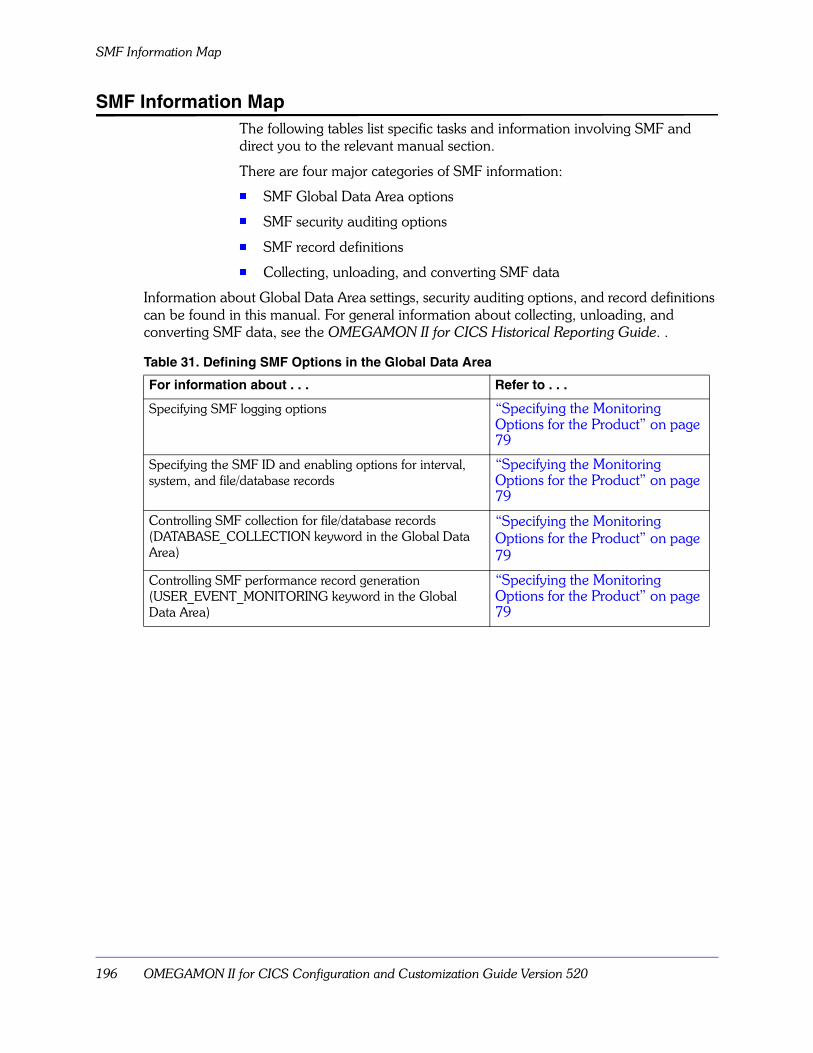
SMF Information Map
196 OMEGAMON II for CICS Configuration and Customization Guide Version 520
SMF Information MapThe following tables list specific tasks and information involving SMF and direct you to the relevant manual section.
There are four major categories of SMF information:
� SMF Global Data Area options
� SMF security auditing options
� SMF record definitions
� Collecting, unloading, and converting SMF data
Information about Global Data Area settings, security auditing options, and record definitions can be found in this manual. For general information about collecting, unloading, and converting SMF data, see the OMEGAMON II for CICS Historical Reporting Guide. .
Table 31. Defining SMF Options in the Global Data Area
For information about . . . Refer to . . .
Specifying SMF logging options “Specifying the Monitoring Options for the Product” on page 79
Specifying the SMF ID and enabling options for interval, system, and file/database records
“Specifying the Monitoring Options for the Product” on page 79
Controlling SMF collection for file/database records (DATABASE_COLLECTION keyword in the Global Data Area)
“Specifying the Monitoring Options for the Product” on page 79
Controlling SMF performance record generation (USER_EVENT_MONITORING keyword in the Global Data Area)
“Specifying the Monitoring Options for the Product” on page 79
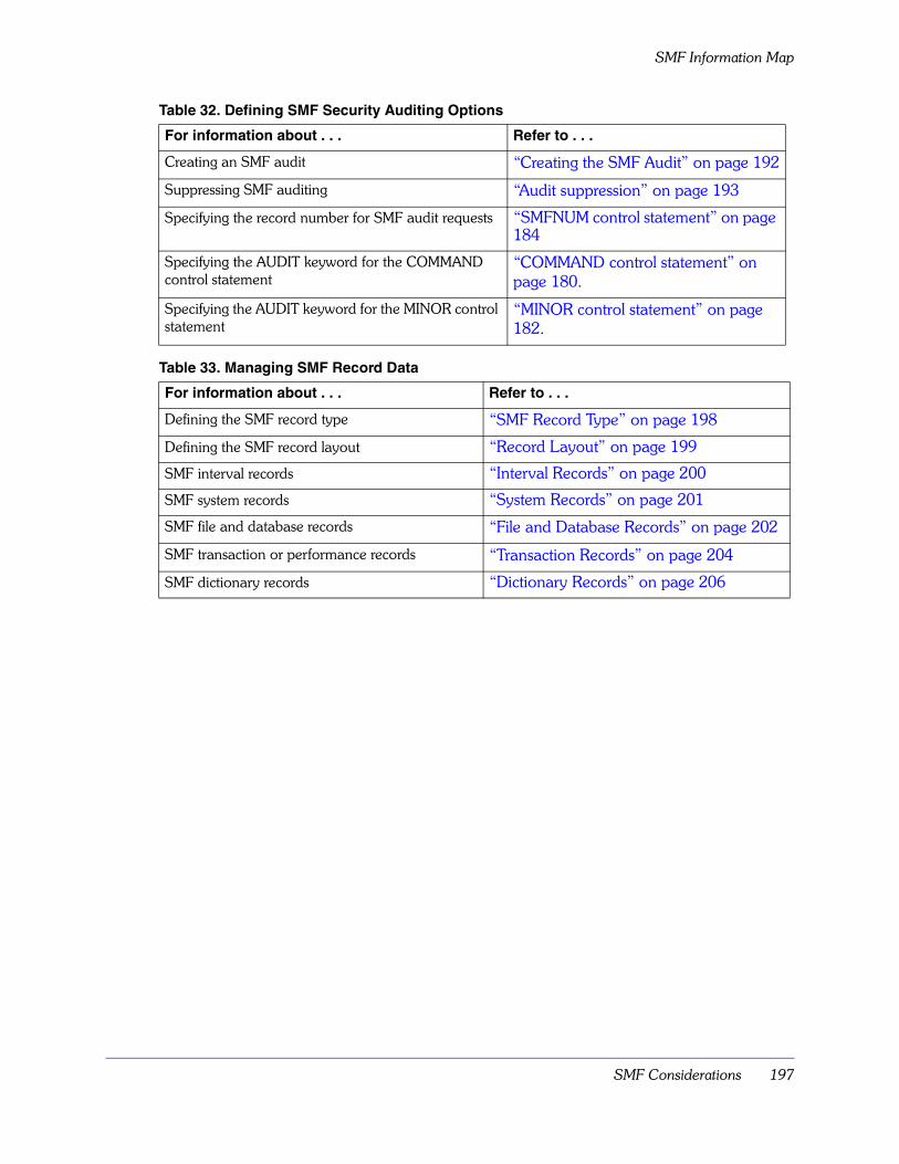
SMF Considerations 197
SMF Information Map
Table 32. Defining SMF Security Auditing Options
For information about . . . Refer to . . .
Creating an SMF audit “Creating the SMF Audit” on page 192
Suppressing SMF auditing “Audit suppression” on page 193
Specifying the record number for SMF audit requests “SMFNUM control statement” on page 184
Specifying the AUDIT keyword for the COMMAND control statement
“COMMAND control statement” on page 180.
Specifying the AUDIT keyword for the MINOR control statement
“MINOR control statement” on page 182.
Table 33. Managing SMF Record Data
For information about . . . Refer to . . .
Defining the SMF record type “SMF Record Type” on page 198
Defining the SMF record layout “Record Layout” on page 199
SMF interval records “Interval Records” on page 200
SMF system records “System Records” on page 201
SMF file and database records “File and Database Records” on page 202
SMF transaction or performance records “Transaction Records” on page 204
SMF dictionary records “Dictionary Records” on page 206

SMF Record Type
198 OMEGAMON II for CICS Configuration and Customization Guide Version 520
SMF Record TypeFor CICS transaction records, the record type is always 110 for CICS/ESA. For CICS/MVS you can change the record type using the USER_EVENT_MONITORING keyword in the Global Data Area.
For all other records, OMEGAMON II uses the SMF record type you specify with the SMFID keyword when you specified the monitoring options for the product using the Global Data Area. The default record type is 255. Audit records are specified in the SMFNUM control statement.
Note: Security audit records do not have a default record type (see“Menu System Security Facility” on page 161).

SMF Considerations 199
Record Layout
Record LayoutEach SMF record contains a standard SMF header followed by an OMEGAMON II header common to all the records. You must use the OMEGAMON II header to identify the record type.
The library thilev.TKANSAM contains Statistical Analysis System (SAS), COBOL, and PL/I record layouts for all the records written by OMEGAMON II. The record layout for the SMF 110 records and OMEGAMON II header portion is found in member:
� KOCSSMF for SAS records
� KOCCSMF for COBOL records
� KOCPSMF for PL/I records
The library thilev.TKANMAC contains assembler record layouts. The record layout for the SMF and OMEGAMON II header portion is found in member KOCSMF in thilev.TKANMAC.
For specific member names of each record layout, refer to the following sections on interval, system, file and database, transaction, and dictionary records.
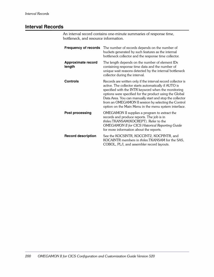
Interval Records
200 OMEGAMON II for CICS Configuration and Customization Guide Version 520
Interval RecordsAn interval record contains one-minute summaries of response time, bottleneck, and resource information.
Frequency of records The number of records depends on the number of buckets generated by such features as the internal bottleneck collector and the response time collector.
Approximate record length
The length depends on the number of element IDs containing response time data and the number of unique wait reasons detected by the internal bottleneck collector during the interval.
Controls Records are written only if the interval record collector is active. The collector starts automatically if AUTO is specified with the INTR keyword when the monitoring options were specified for the product using the Global Data Area. You can manually start and stop the collector from an OMEGAMON II session by selecting the Control option on the Main Menu in the menu system interface.
Post processing OMEGAMON II supplies a program to extract the records and produce reports. The job is in thilev.TKANSAM(KOCREPT). Refer to the OMEGAMON II for CICS Historical Reporting Guide for more information about the reports.
Record description See the KOCSINTR, KOCCINT2, KOCPINTR, and KOCAINTR members in thilev.TKANSAM for the SAS, COBOL, PL/I, and assembler record layouts.
SMF Considerations 201
System Records
System RecordsEach time OMEGAMON II starts and stops monitoring a CICS region, OMEGAMON II creates a system record that contains MVS-related statistics as well as copies of the common system area (CSA) and system initialization table (SIT) from CICS. This can happen in either of the following ways:
� OMEG INIT or OMEG SHUT
� PLT startup or shutdown when the KOCOME00 program is executed
See “Stopping the Collector” on page 108 for information about the OMEG INIT and OMEG SHUT transaction. For more information about the KOCOME00 program, see “Modifying the CICS Tables and JCL” on page 65.
Frequency of records One record when OMEGAMON II starts to monitor a CICS region and one record when OMEGAMON II stops monitoring a CICS region.
Approximate record length
Record length depends on your CICS version.� CICS Version 2.1.2 approximately 3298 bytes� CICS Version 3.2.1 approximately 4082 bytes� CICS Version 3.3 approximately 4236 bytes� CICS Version 4.1 and above approximately 4404
bytes
Controls Records are always written.
Post processing OMEGAMON II converts these records to produce the System Detail Report. Refer to the OMEGAMON II for CICS Historical Reporting Guide for more information about the report and the record conversion.
Record description Refer to the KOCSSREC, KOCCSREC, KOCPSREC, and KOCASREC members of thilev.TKANSAM for the SAS, COBOL, PL/I, and assembler record layouts.

File and Database Records
202 OMEGAMON II for CICS Configuration and Customization Guide Version 520
File and Database RecordsOMEGAMON produces records detailing the file and database usage for each CICS transaction. These records contain counts and elapsed times for each type of file or database command that a transaction issues. These records are intended to be used along with the CICS type 110 SMF records.
The creation of file and database SMF records is controlled by the DATABASE_COLLECTION keyword in the Global Data Area. You must define one for each file or database product for which you want data collected. In addition, third-party products require the steps described in “Installing Third-Party Support” on page 207.
Frequency of records One record for each transaction for each file or database product used by the transaction. If a single transaction accesses both DL/I and native VSAM, a file and a database record (2 records) will be produced. One will contain DL/I statistics, and the other will contain VSAM statistics.
Approximate record length
Each record has a totals segment followed by a detail segment for each file or database accessed during the transaction.
The number of files or databases accessed during the life of the transaction determines the number of bytes in each record. The table below demonstrates this relationship for each record type.
Record Type Record Length (in bytes)
VSAM (CICS File Control) 140 + (68 x number of files accessed)
ADABAS 172 + (100 x number of files accessed)
CA-DATACOM 256 + (108 x number of files accessed)
DL/I 180 + (108 x number of files accessed)
IDMS 180 + (108 x number of files accessed)
SUPRA 180 + (60 x number of files accessed)
Controls Records are written based on the parameter in the DATABASE_COLECTION keyword in the Global Data Area for the particular file or database product.
You can also turn logging on or off dynamically from an OMEGAMON II session by selecting the Control option on the Main Menu in the menu system interface.
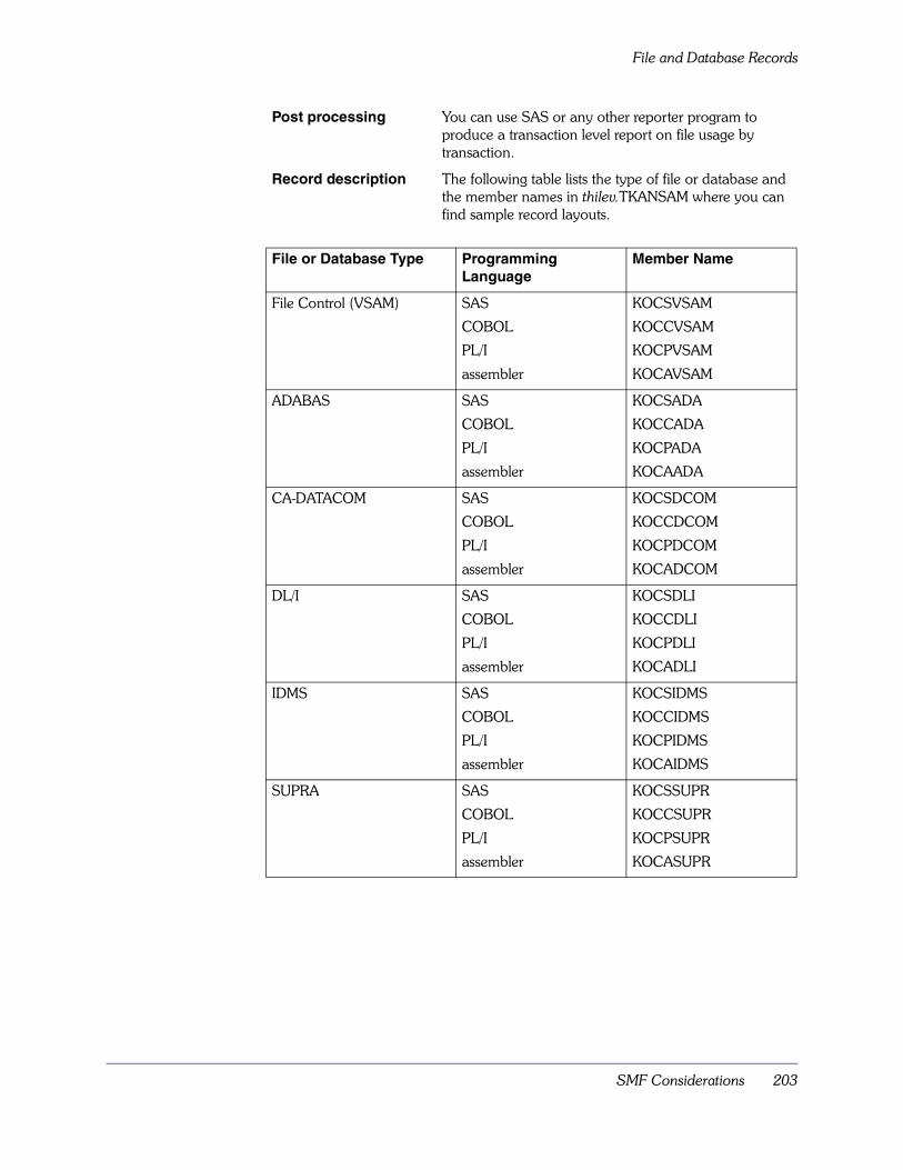
SMF Considerations 203
File and Database Records
Post processing You can use SAS or any other reporter program to produce a transaction level report on file usage by transaction.
Record description The following table lists the type of file or database and the member names in thilev.TKANSAM where you can find sample record layouts.
File or Database Type Programming Language
Member Name
File Control (VSAM) SAS
COBOL
PL/I
assembler
KOCSVSAM
KOCCVSAM
KOCPVSAM
KOCAVSAM
ADABAS SAS
COBOL
PL/I
assembler
KOCSADA
KOCCADA
KOCPADA
KOCAADA
CA-DATACOM SAS
COBOL
PL/I
assembler
KOCSDCOM
KOCCDCOM
KOCPDCOM
KOCADCOM
DL/I SAS
COBOL
PL/I
assembler
KOCSDLI
KOCCDLI
KOCPDLI
KOCADLI
IDMS SAS
COBOL
PL/I
assembler
KOCSIDMS
KOCCIDMS
KOCPIDMS
KOCAIDMS
SUPRA SAS
COBOL
PL/I
assembler
KOCSSUPR
KOCCSUPR
KOCPSUPR
KOCASUPR

Transaction Records
204 OMEGAMON II for CICS Configuration and Customization Guide Version 520
Transaction RecordsTransaction records contain resource usage and performance-related statistics for each CICS transaction. For CICS/MVS, OMEGAMON II collects these statistics and writes records to SMF as an alternative to the CICS Monitoring Facility (CMF). For CICS/ESA, transaction records are produced by CMF.
The following table describes some characteristics of transaction records produced on CICS/MVS and CICS/ESA.
If you define the OMEGAMON II user-event monitoring points in the MCT for CICS/ESA, OMEGAMON II also collects DB2 and DL/I clock and counter statistics. See“Modifying the CICS Tables and JCL” on page 65 for information about adding definitions to the MCT and for a list of required fields in the MCT for CICS/ESA.
IF you have... THEN... AND...
CICS/MVS a record is produced for each conversation records are written to SMF as type 110 performance records or as the type you specified in the Global Data Area
CICS/ESA a record is produced for each conversation if you have set CONV=YES in your CICS MCT for CICS version 3 or if you have set MNCONV=YES in your SIT for CICS version 4 and above.
records are written to SMF as type 110 performance records.
SMF Considerations 205
Transaction Records
Frequency of records
Data is written to a buffer for each transaction or conversation. When the buffer is full, the contents are written to SMF. The rate at which the buffer fills and is written to SMF varies with the rate of transactions.
Approximate record length
For CICS/MVS, the record is about 480 bytes. For CICS/ESA, if you define all of the OMEGAMON II user event monitoring points in the MCT, an additional 308 bytes is appended to the CMF record.
Controls For CICS/MVS, OMEGAMON II writes records to SMF based on the value specified in USER_EVENT_MONITORING in the Global Data Area.
For CICS/MVS, do not turn on CMF if the parameter is set to YES or an SMF number. If you do, you will receive two SMF records for each transaction, one each for CMF and OMEGAMON II.
For CICS/MVS, the value collected for transaction CPU time by OMEGAMON II (DFHTASK_008 in CMF) is likely to be lower than that of CMF. OMEGAMON II has its own collection methodology, and measures the aggregate CPU time accrued by user application code exclusive of that used by CICS system services.
For CICS/ESA, an active CMF writes records to SMF unless they are suppressed with the SMFCICS3 keyword set to NO. If you want CMF records in CICS/ESA, you must set the SMFCICS3 keyword to YES.
For all releases of CICS, you can also selectively suppress the writing of transaction records based on transaction ID. Refer to the USER_EVENT_MONITORING keyword in the Global Data Area for more information.
Post processing You can convert these records and use the historical reporter to produce batch reports.
Refer to the OMEGAMON II for CICS Historical Reporting Guide for more information on record conversion and the reports.
Record description Refer to the KOCSTRAN, KOCCTRAN, and KOCPTRAN members in thilev.TKANSAM for the SAS, COBOL, and PL/I record layouts.
In addition, refer to these members to map the OMEGBSC event monitoring point, which is part of the transaction record. For general information on all of these members, see KOC$DEF.
For CICS version 2, see members KOCAPERF, KOCSPERF, KOCCPERF, and KOCPPERF. For the assembler record layouts, see member KOCPERF thilev.TKANMAC. For general information on all of these members, see KOC$DEF2.
Note: OMEGAMON II produces a basic format of SMF 110 record according to the rules described in CICS Customization Guides. However, these formats may change due to maintenance and development activities of CICS.
Dictionary Records
206 OMEGAMON II for CICS Configuration and Customization Guide Version 520
Dictionary RecordsDictionary records describe the contents of SMF type 110 records and are required when reporting on transaction records.
For CICS/MVS, OMEGAMON II writes a dictionary record when program KOCOME00 is executed in the PLTPI or during the OMEG INIT transaction (if CICSESA_SMF_RECORDS=YES is coded in the Global Data Area).
For CICS/ESA, CICS writes a dictionary record during CICS startup or whenever CMF recording of transaction records is enabled (by a CEMT SET MONITOR command, for example).

Installing Third-Party Support 207
Installing Third-Party Support
Chapter OverviewOMEGAMON II can monitor several third-party database and fourth-generation language products. This chapter describes how to install support for them.
Chapter ContentsBackground about the Products Supported . . . . . . . . . . . . . . . . . . . . . . 208Installing ADABAS Support . . . . . . . . . . . . . . . . . . . . . . . . . . . . . . . . . . 210Installing CA-DATACOM and CA-IDEAL Support . . . . . . . . . . . . . . . . . . 211Installing GENER/OL Support . . . . . . . . . . . . . . . . . . . . . . . . . . . . . . . . 212Installing IDMS Support . . . . . . . . . . . . . . . . . . . . . . . . . . . . . . . . . . . . . 213Installing Millennium Support . . . . . . . . . . . . . . . . . . . . . . . . . . . . . . . . . 215Installing NATURAL Support . . . . . . . . . . . . . . . . . . . . . . . . . . . . . . . . . 216Installing PCS Support . . . . . . . . . . . . . . . . . . . . . . . . . . . . . . . . . . . . . . 217Installing SUPRA Support . . . . . . . . . . . . . . . . . . . . . . . . . . . . . . . . . . . . 218Installing UFO/Forms Support. . . . . . . . . . . . . . . . . . . . . . . . . . . . . . . . . 219
15
Background about the Products Supported
208 OMEGAMON II for CICS Configuration and Customization Guide Version 520
Background about the Products SupportedThe database products supported are:
� ADABAS
� CA-DATACOM
� IDMS (excluding UCF applications)
� SUPRA
OMEGAMON II provides the following information:
� Count and elapsed times of database calls per transaction. This data is available through Task History panels of the CUA interface, the ONDV command of the menu system interface, or as SMF records for batch historical reporting. See “SMF Considerations” on page 195.
� The database name. This data is collected as part of the waiting resource name during the database call. The waiting resource name is used in task displays and internal bottleneck analysis.
The fourth-generation language products supported are:
� CA-IDEAL
� GENER/OL
� Millennium
� NATURAL
� PCS
� UFO/Forms
OMEGAMON II supplies the application name as the umbrella program name on the Task History panels of the CUA interface, ONDV command output in the menu system interface, and in SMF 110 records for historical reporting.
Notes:
1. The supported products and the steps you must take to provide that support may change. Before installing support for any of the third-party products listed, you must
� check the Preventative Service Planning documentation
� contact Candle Customer Support to ensure that you have the latest support and any required maintenance.
2. When installing a new release of OMEGAMON II or doing a major maintenance upgrade, we recommend that you investigate the likelihood that you will have to reimplement TPPS facilities.
Installing Third-Party Support 209
Background about the Products Supported
Support ConsiderationsIf you are running CICS/ESA or above and have not already done so, define the OMEGAMON II entries to your CICS monitoring control table (MCT), as described in “Monitoring Control Table (MCT)” on page 68, before you begin any installation of a database or fourth-generation product.
After performing the installation steps, you must restart your OMEGAMON II and CICS regions, as described in the following sections.

Installing ADABAS Support
210 OMEGAMON II for CICS Configuration and Customization Guide Version 520
Installing ADABAS SupportThe OMEGAMON II support for ADABAS provides two user exits that you must assemble and link-edit into the ADABAS/CICS interface module during installation.
The ADABAS/CICS interface modules are:
� ADALNC, a macro level program used for CICS Version 2.1.2
� LNKOLSC, a command level program used for CICS releases 3.2 and higher
If you are using a driver program to execute multiple exits at either ADABAS exit point, you must modify the supplied exits to conform to the standards required by the driver program.
To install ADABAS support, follow the steps below.
1. Assemble and link-edit the two Candle-supplied ADABAS user exits. The source for these exits and the JCL to assemble and link-edit them appears in the KOCADABA member of thilev.TKANSAM.Note: If you define an RTE that uses the SMP libraries, you must concatenate the TKANMOD load library to the LKED SYSLIB DD as follows:
//LKED EXEC ...
//SYSLIB DD DISP=SHR,DSN=&RHILEV..RKANMOD
// DD DISP=SHR,DSN=&THILEV..TKANMOD
2. Assemble and link-edit the ADABAS/CICS interface module. Make sure that the USERSAV save area is set to at least 72 bytes.When link-editing, include the rhilev.RKANMOD library in the SYSLIB concatenation sequence and add the following statement to SYSIN:
INCLUDE SYSLIB(UEXITA,UEXITB)
3. Restart your CICS and menu system address spaces to enable monitoring.

Installing Third-Party Support 211
Installing CA-DATACOM and CA-IDEAL Support
Installing CA-DATACOM and CA-IDEAL SupportSupport for CA-DATACOM is available for Versions 7.5 to 8.1 inclusive.
1. Add the following Candle-supplied macros to the DCSF exit, DCCTXPR, depending on� the version of DATACOM in use at your site
� the version of DCSF in use at your site
Note: If you are using DCSF Version 2.5, make sure that the branch address at label TEMP in exit DCCTXPR is changed from label RETURN to label OVERHEAD.
2. Assemble and link-edit DCCTXPR.a. When assembling, include the thilev.TKANMAC library (supplied
by Candle) and the CICS macro and AMACLIB libraries (supplied by IBM) in the SYSLIB concatenation sequence for assembling. (You need the CICS and AMACLIB libraries for the IKJTCB macro.) If the assembly job contains errors, verify that you correctly concatenated the above libraries into SYSLIB.
b. When link-editing, include the rhilev.RKANMOD library in the SYSLIB concatenation sequence and add the following statement to SYSIN:
INCLUDE SYSLIB(KOCFIN00)
Note: If your RTE uses the SMP libraries, include thilev.TKANMOD in the SYSLIB concatenation.
3. Specify NAME=DATACOM for DATABASE_COLLECTION in the Global Data Area. (See“Specifying the Monitoring Options for the Product” on page 79 for more information.)
Table 34. DATACOM Support Macros
DATACOM Version
DCSF Version
Install macro After DCCTXPR label
7.5 2.4 KOCDCOM7 D10000
8.0 or 8.1 2.4 KOCDCOM8 D10000
8.0 or 8.1 2.5 KOCDC832 (if using CICS 3.1 or greater)
OVERHEAD
8.0 or 8.1 2.5 KOCDC832 CICS212=YES
(Remove DFHUEXIT if coded—if using CICS 2.1.2)
OVERHEAD

Installing GENER/OL Support
212 OMEGAMON II for CICS Configuration and Customization Guide Version 520
Installing GENER/OL SupportTo install GENER/OL support, follow these steps:
1. Add an entry to the PPT for KOCGENcc, with the attributes of assembler and resident.
2. Replace the cc in KOCGENcc with the 2-character suffix that represents the version of CICS you are running, as shown in the following table.
3. Select option 4, Security from the GENER/OL Customize Task Exit Parameters panel. (See the GENER/OL System Administration and Security Guide for more information about this panel.) The System Administration Menu displays.
4. Select option 4, Customize, from the System Administration Menu. The Customize Task Parameters menu displays.
5. Enter the following information on the Customize Task Parameters menu:� KOCGENcc for the program name
� L for Use Branch Entry or CICS Link
� Yes for GENER/OL Initialization
� NO for all other fields
6. Restart GENER/OL.
Table 35. KOCGEN Suffix for CICS Releases
CICS Release Suffix
2.1.2 C0
3.2.1 H0
3.3 I0
4.1 J0
5.1 K0

Installing Third-Party Support 213
Installing IDMS Support
Installing IDMS SupportThis section describes how to install IDMS support for versions 10 and 12. To install support for IDMS, you must modify the IDMS-supplied macro IDMSINTC with Candle macros by following the procedure below.
1. Make a copy of the IDMSINTC macro.� For Version 10, modify this copy by inserting KOCAIDMS START after
the statement that generates the following set of installation instructions.
Insert KOCAIDMS STOP after the statement that generates the following set of installation instructions.
� For Version 12, make a copy of the IDMSINTC macro. Modify this copy by inserting the statement KOCAID12 START as shown below. The instructions are located near the label NOOPTI.
Insert the statement KOCAID12 STOP as shown below.
2. Reassemble and link the module. You must include the thilev.TKANMAC and the IBM AMODGEN datasets in the SYSLIB concatenation for the assemble step.The link-edit step must also include:
a. the rhilev.RKANMOD library in the SYSLIB concatenation Note: If your RTE uses the SMP libraries, include thilev.TKANMOD in the SYSLIB concatenation.
b. the following control statement for the linkage editor: INCLUDE SYSLIB(KOCFIN00)
IDMSINC1 STM R14,R12,12(R13)L R9,BASELR R8,R13L R13,CSAADDRL R12,CSACDTAKOCAIDMS START
IDMSINC2 STM R14,R12,12(R13)L R9,BASELR R8,R13L R13,CSAADDRL R12,CSACDTAKOCAIDMS STOP
L R1,CALLERSV+24 R1 -> CALLER’S PLISTKOCAID12 STARTB *(R5)
XXIDMS DS 0HKOCAID12 STOPB *(R5) GO BASED ON TYPE OF CALL
Installing IDMS Support
214 OMEGAMON II for CICS Configuration and Customization Guide Version 520
Candle recommends that you save a copy of the IDMSINTC source prior to making any changes.
3. Specify NAME=IDMS for DATABASE_COLLECTION in the Global Data Area. (See“Specifying the Monitoring Options for the Product” on page 79 for more information).Note: IDMS support does not cover UCF ad hoc, non-Data-Manipulation-Language (DML) queries via the IDMS Dedicated Mode facility, because no DML requests are issued from the CICS region.

Installing Third-Party Support 215
Installing Millennium Support
Installing Millennium SupportIf you are running CICS Version 3, you must define the user event monitoring point OMEGBSC to your MCT. Refer to “Modifying the CICS Tables and JCL” on page 65 for more information.
You must also add USER_EVENT_MONITORING and STARTUP_CONTROL to specify the name of the user event monitoring point. See “Specifying the Monitoring Options for the Product” on page 79 for more information.
If you are running CICS Versions 1 or 2, no MCT is required.
To install Millennium support, follow these steps:
1. Change the Millennium Program M2X000 as follows:a. Add the following to the working storage section:
01 OMEG-WORK AREA.
05 OMEG-REQ PIC S9(8) COMP VALUE +7.
05 OMEG-SCRID PIC X(5) VALUE SPACE.
b. Add the following after the label L000-Process-Security. MOVE TS-SCR-SCREEN TO OMEG-SCRID.
CALL KOCRMCLL USING OMEG-REQ OMEG-SCRID.
2. Recompile and relink M2X000, as follows:a. Add the rhilev.RKANMOD library to the SYSLIB statement of the
link-edit step.Note: If your RTE uses the SMP libraries, include thilev.TKANMOD in the SYSLIB concatenation.
b. Add the statement INCLUDE SYSLIB(KOCRMCLL) to the link-edit SYSIN.
3. Examine the output of the compile and link-edit for any error messages. Be sure that the KOCRMCLL reference was resolved during link-editing.

Installing NATURAL Support
216 OMEGAMON II for CICS Configuration and Customization Guide Version 520
Installing NATURAL SupportOMEGAMON II NATURAL support runs as an exit to the NATURAL Review Data Collector. Both the NATURAL Review Data Collector and the OMEGAMON II NATURAL support exit must be link-edited into a NATURAL Shared Nucleus (NSN). The OMEGAMON II NATURAL support exit is a TP-specific module for the CICS environment, and, as such, must be included as part of a “Single-Environment Shared Nucleus” for CICS. Please refer to the NATURAL Operations Manual for more information regarding the NATURAL Shared Nucleus, TP-specific modules, and “Single-Environment Shared Nuclei.”
To install NATURAL support, follow these steps:
1. Verify that the OMEGAMON II NATURAL exit is available. This is program KOCATL00 found in the rhilev.RKANMOD library.
2. It is important to follow the instructions found in the NATURAL Operations Manual for the creation of an NSN as a “Single-Environment Shared Nucleus.”
3. Follow the instructions for link-editing the NATURAL Review Data Collector—NATRDC—into an NSN as provided by the vendor.
4. Add the following DD statement for the OMEGAMON II load library to the job used to link-edit the NSN:
//RKANMOD DD DISP=SHR,DSN=rhilev.RKANMOD
Note: If your RTE uses the SMP libraries, add the following DD statement instead:
//RKANMOD DD DISP=SHR,DSN=thilev.TKANMOD
5. Add the following linkage-editor control statement to the linkage-editor input stream after the INCLUDE statement for NATRDC:
INCLUDE RKANMOD(KOCATL00)

Installing Third-Party Support 217
Installing PCS Support
Installing PCS SupportIf you are running CICS Version 3 or above, you must define the user event monitoring point OMEGBSC to your MCT. Refer to“Modifying the CICS Tables and JCL” on page 65 for more information.
You must also add USER_EVENT_MONITORING and STARTUP_CONTROL to specify the name of the user event monitoring point. See “Specifying the Monitoring Options for the Product” on page 79 for more information. If you are running CICS Versions 1 or 2, no MCT is required.
1. Make the following changes to the PCS program DOCSCMAN:a. Locate the statement
PERFEMP SENTER
b. After the instruction MVC WKASCNAM,TWASCAM
add the following instructions if you have V1R2:
ST 13,DFHEIR13
LA 13,DFHEISA
MVC WKAFNCID(4),=F’7’
LA 14,WKAFNCID
LA 15,WKASCNAM
CALL KOCRMCLL,((14),(15)),VL
L 13,DFHEIR13
Add the following instructions if you have PCS V1R3:
MVC WKAFNCID(4),=’7’
LA 14,WKAFNCID
LA 15,WKASCNAM
CALL KOCRMCLL,((14),(15)),VL
2. Assemble and link-edit DOCSCMAN.a. Add the rhilev.RKANMOD library to the SYSLIB statement of the
link-edit step. (Note: If your RTE uses the SMP libraries, include thilev.TKANMOD in the SYSLIB concatenation.)
b. Add the statement to SYSIN INCLUDE SYSLIB(KOCRMCLL)
3. Examine the output of the ASM.a. Link-edit for any error messages.b. Make sure the KOCRMCLL was resolved in the link-edit step.
4. Recycle your CICS region.
Installing SUPRA Support
218 OMEGAMON II for CICS Configuration and Customization Guide Version 520
Installing SUPRA SupportYou can install support for SUPRA versions 1 and 2.
To install support for SUPRA version 1 or SUPRA version 2, follow these steps:
1. Assemble and link-edit the SUPRA:� Pre-command exit (CSTEXT01), which is delivered in
thilev.TKANSAM(KOCCST01), for SUPRA version 1, or thilev.TKANSAM(KOCSUPR1), for SUPRA version 2.
� Post-command exit (CSTEXT02), which is delivered in thilev.TKANSAM(KOCCST02), for SUPRA version 1, or thilev.TKANSAM(KOCSUPR2). for SUPRA version 2.
a. When assembling, include your CICS macro library in the SYSLIB.
b. Link-edit the exits into your OMEGAMON II load library.When link-editing, include the rhilev.RKANMOD library in the SYSLIB concatenation sequence and add the following statement to SYSIN:
INCLUDE SYSLIB(KOCFIN00)
Notes:
1. If you already use these exits for other purposes, you can modify them based on the source delivered in thilev.TKANSAM(KOCCST01) and thilev.TKANSAM(KOCCST02) for SUPRA version 1, or thilev.TKANSAM(KOCSUPR1) and thilev.TKANSAM(KOCSUPR2), for SUPRA version 2.
2. If your RTE uses the SMP libraries, include thilev.TKANMOD in the SYSLIB concatenation.
2. Link-edit the PDM interfaces with CSTEXT01 and CSTEXT02. See the SUPRA PDM Administrator Guide for more information on linking the interface exits.
Installing Third-Party Support 219
Installing UFO/Forms Support
Installing UFO/Forms SupportTo install UFO/Forms support, follow these steps:
1. Add an entry to the PPT for KOCUFO00 with the attributes of assembler and resident.
2. Identify KOCUFO00 as an accounting exit to UFO/Forms. You can do this in one of two ways: � Use the CICS utility UFOINIT. (The change will remain in effect only as
long as CICS is running.)
� Update the CICS UFMAINIT macro (The exit is always available.)
For more information about installing UFO/Forms, see the section on Accounting Exits in the UFO/Forms Customization and Operation Guide.

Installing UFO/Forms Support
220 OMEGAMON II for CICS Configuration and Customization Guide Version 520
Umbrella Transaction Services 221
Umbrella Transaction Services
Chapter OverviewTo analyze transactions from a different perspective, OMEGAMON II supplies two subroutines, KOCRMCLL and KOCGLCLL. These subroutines modify certain values associated with a transaction.
This chapter describes the KOCRMCLL and KOCGLCLL subroutines and how to use them.
Chapter ContentsUsing Subroutines . . . . . . . . . . . . . . . . . . . . . . . . . . . . . . . . . . . . . . . . . 222Subroutine Call Syntax. . . . . . . . . . . . . . . . . . . . . . . . . . . . . . . . . . . . . . 223
16

Using Subroutines
222 OMEGAMON II for CICS Configuration and Customization Guide Version 520
Using SubroutinesUsing KOCRMCLL and KOCGLCLL, you can supply
� an additional transaction ID for task analysis, the response time collector, task history collector, and SMF records
� an additional program name for task analysis, the response time collector, task history collector, and SMF records
� a different resource name and resource type for task analysis and internal bottleneck analysis
� an additional 32 bytes of data for each task record written to SMF
KOCRMCLL and KOCGLCLL replace the umbrella service facility from prior releases of OMEGAMON II. All programs using OMUMBSUB or UMBFIND must be converted to use these new routines. OMUSEREC is no longer supported.
KOCRMCLL and KOCGLCLL provide similar functions. Their use depends on the CICS environment in which they are called.
KOCRMCLL can run as part of any CICS application code, including a CICS task-related user exit. It cannot be used in a CICS global user exit.
Prior to the call to KOCRMLL, you have to acquire a standard save area. You should store register one (holding the pointer to the parameter list for KOCRMLL) in the correct place of this save area (ST 1,24,(13) or STM 14,12,12(13), where register 13 addresses the new save area). The new save area should be chained to the previous one.
KOCGLCLL can run as part of any CICS application code and any CICS global user exit.
When either KOCRMCLL or KOCGLCLL is invoked, the fields that are changed stay in effect until a subsequent call changes or clears them. A field is cleared at the end of a conversation if CONV=YES is specified in the CICS monitoring control table (MCT). You can retain the field across conversations, however.
If you are using CICS/ESA and you want to use these fields for the historical displays such as the task history and response time panels, you must define a user event monitoring point for the basic section. For task analysis and internal bottleneck analysis, the event monitoring point is not required.
Note: If you want more information, see member KOCAPITX in thilev.TKANSAM.
Umbrella Transaction Services 223
Subroutine Call Syntax
Subroutine Call SyntaxThe syntax for calling KOCRMCLL is shown below:
CALL KOCRMCLL,(request,parm),VL
The parameters for the KOCRMCLL subroutine call are described as follows:
The syntax for calling KOCGLCLL is shown below:
CALL KOCGLCLL,(workarea,rc,request,parm),VL
The parameters for the KOCGLCLL subroutine call are described below.
request Specifies a full word containing the number of the requested operation. For the list of possible requests, see Figure 15 on page 224.
parm Specifies an area of storage used to move a value into or a field out of the transaction record. See Figure 15 on page 224 for the required length, which depends on the request.
VL Specifies the end of the list of parameters.
workarea Specifies the full word that must be initialized to hex 00s the first time KOCGLCLL is used. Subsequent calls to KOCGLCLL should use the same field unaltered.
rc Specifies the full word containing the return code. Possible return codes are as follows:
0 Normal completion.
4 Invalid request code.
8 OMEGAMON II has not initialized in the CICS region. Make sure KOCOME00 is in the PLTPI or enter the transaction OMEG INIT.
12 Incomplete parameter list provided.
request Specifies a full word containing the number of the requested operation. For the list of possible requests, see the following figure.
parm Specifies an area of storage used to move a value into or a field out of the transaction record. See the following figure for the required length, which depends on the request.
VL Specifies the end of the list of parameters.
For KOCRMCLL, the return code is set in Register 15 for Assembler programs or in the appropriate variables for COBOL and PL1 programs.
The following figure lists the possible types of requests.

Subroutine Call Syntax
224 OMEGAMON II for CICS Configuration and Customization Guide Version 520
FIGURE 15. List of Requests for KOCRMCLL
Each field is described below.
MN#FLAG4 This flag contains two indicators that you set if you want the values you supply for MN#UMBPTC, MN#DEXFIL, and MN#DEXTYP to be carried over the end of a transaction conversation. Call KOCRMCLL to read the current field (REQUEST # = 2); set the bit corresponding to the field you want carried across to 1; and call KOCRMCLL to write the field (REQUEST # =3). Refer to the dsects for the bit settings.
MN#UMBPTC Set this field with an alternate transaction ID. The Task, Response Time, and History menu paths display this ID name in place of the actual transaction ID. You can change the value several times over the course of the task, but the response time collector and task history collector pick up only the last setting. Changing the value does not cause an individual record to be written. Rather, it allows you to highlight the phase of the task with the TASK menu option.
One popular use of this field is to supply a meaningful name to a CICS application that runs under a transaction ID used for many programs. For example, many fourth-generation language packages use one transaction ID to invoke many applications. By supplying a new transaction ID, you can get a clearer indication of the application that was running as part of that transaction.
MN#UMBUSR Set this field with an alternate program name. The Task Details panel (KC2C02D) and the Task History Details panel (KC2T02D) will display the umbrella pushbutton. Selecting this button will display either panel Task Umbrella Data (KC2C09D) or panel Task History Umbrella Data (KC2T06D). These panels will display MN#UMBUSR as the umbrella program ID.
REQUEST DESCRIPTION PARAMETER FIELD NAMENUMBER FIELD LENGTH-----------------------------------------------------------------------2 READ FLAG FIELD 1 MN#FLAG43 WRITE FLAG FIELD 1 MN#FLAG44 READ UMBRELLA TRANSACTION PSUEDO 4 MN#UMBPTC5 WRITE UMBRELLA TRANSACTION PSEUDO 4 MN#UMBPTC6 READ UMBRELLA PROGRAM NAME 8 MN#UMBUSR7 WRITE UMBRELLA PROGRAM NAME 8 MN#UMBUSR8 READ WAITING RESOURCE NAME 8 MN#DEXFIL9 WRITE WAITING RESOURCE NAME 8 MN#DEXFIL
10 READ WAITING RESOURCE TYPE 8 MN#DEXTYP11 WRITE WAITING RESOURCE TYPE 8 MN#DEXTYP12 READ USER DATA 32 MN#USRWK13 WRITE USER DATA 32 MN#USRWK
Umbrella Transaction Services 225
Subroutine Call Syntax
MN#DEXFIL This field is used in task displays and internal bottleneck analysis and represents the resource name that the task is waiting on. The resource name is normally supplied by CICS. Supplying a new resource name can give you a clearer indication of the reason for the wait.
For example, you may have a transaction that issues requests to database products. While the transaction is waiting for a service to complete, it normally appears to be waiting on an MVS ECB, which really gives no indication of the type of wait. By calling KOCRMCLL before the request, you can supply a name that clearly identifies the type of wait, such as a database product name or function type. When the transaction receives control back from the database product, you can call KOCRMCLL again to clear out this waiting resource name.
MN#DEXTYP This field is used in task displays and internal bottleneck analysis and represents the resource type that the task is waiting on. The resource type is normally supplied by CICS. This field is used the same way as MN#DEXFIL.
MN#USRWK Use this field as a work area for user data.

Subroutine Call Syntax
226 OMEGAMON II for CICS Configuration and Customization Guide Version 520

Collector Address Space 227
Collector Address Space
Appendix OverviewThe collector is an address space that is separate from the CICS address space. The collector can accept commands from either a member of its parameter library or an MVS operator’s console. With these commands you can do any of the following:
� Start OMEGAMON II monitoring sessions with a different set of startup parameters for each session. For example, each session can pass the address of a different, dedicated, local 3270 to use as its output device.
� Start the OMEGAMON II VTAM application, OBVTAM. Once this program is running under the collector, any 3270 terminal in your VTAM network (depending on authorization) can log on to the program and have its own OMEGAMON II session.
� Display all subtasks currently running under the collector.
� Stop any subtask running under the collector.
Appendix ContentsCollector Operation . . . . . . . . . . . . . . . . . . . . . . . . . . . . . . . . . . . . . . . . 228Interface Commands . . . . . . . . . . . . . . . . . . . . . . . . . . . . . . . . . . . . . . . 229Installing Multiple Collector Address Spaces . . . . . . . . . . . . . . . . . . . . . . 237
A

Collector Operation
228 OMEGAMON II for CICS Configuration and Customization Guide Version 520
Collector OperationYou can enter commands to the collector through the OMEGAMON II menu system by performing the following steps:
1. Select U, UTILITIES, from the main menu.
2. Select M, INTERFACE, from the utilities menu.Figure 16 on page 228 appears:
FIGURE 16. Issue Collector Command Menu Panel
Follow the instructions on the panel to enter collector commands.
________________ ZUOCCI VTM CICSPROD V400./I SYSA 09/19/99 12:15: 21> PF1 Help PF3 Back PF4 Main Menu PF7 Up PF8 Down
==============================================================================> ISSUE COLLECTOR COMMAND
> To issue an OCCI command, replace the > preceding CICM with a hyphen and> replace DISPLAY with the required OCCI command.
>CICM DISPLAY
> To display console output:> - Blanks after CONS indicate the master terminal. You may enter an MVS> console ID after CONS.> - Replace 10 after LINE with the number of lines at the bottom to display.
-CONS Master Console 6A2 ( Id=2 )line10
+ - 087D0001+ - 10.42.50 STC08737 IST895I CCCDRM26 08420000 CCCD00
. . . . .
. . . . .
. . . . .
> If a password is required, enter /PWD on the top line. At the prompt, enter> the password.===============================================================================

Collector Address Space 229
Interface Commands
Interface CommandsInterface commands allow you to perform functions such as displaying collector subtasks, starting or stopping the collector subtask, or sending a message to the console. They can be stored as members in the rhilev.RKANPAR library.
To use the stored interface commands, perform the following steps:
1. Create a member in the rhilev.RKANPAR library.
2. Use the EXEC command to process the member. You can either enter this command via MODIFY or as a command in an EXEC member.Note: All commands from the console must be preceded by the MODIFY command and the modify ID.
You can start the commands in the EXEC members of rhilev.RKANPAR in any column as long as you complete the command word before column 72. (You can continue the command by placing any character in column 72.) The following list defines the commands that the collector supports.
Collector comment (*)In members of the rhilev.RKANPAR library, use an asterisk (*) in column 1 of any line to comment out the text to follow. Use a nonblank character in column 72 to continue the comment. An example of a comment line in an EXEC member follows:
* Comment (ignored by the collector), must begin in column 1.
DISPLAY Displays active collector subtasks.
EXEC Executes the commands in the specified member.
HELP Displays help for all or specific collector commands.
LIST Alias of DISPLAY; displays active collector subtasks.
LOG Sends a message to the MVS console.
START Starts a collector subtask (for example, OMEGAMON II).
STOP Stops a collector subtask.
* THIS COMMENT CAN SAY ANYTHING YOU WISH.

Interface Commands
230 OMEGAMON II for CICS Configuration and Customization Guide Version 520
DISPLAY commandThe DISPLAY command lists all tasks that are currently active. An internal ID is displayed along with the program name of the task.
An example of output from the DISPLAY command appears in the following figure.
FIGURE 17. DISPLAY Command Output
Each task has a unique ID. The ID of a subtask associated with a specific CICS region consists of the program name combined with the CICS jobname. That is, subtask in Figure 17 on page 230 will be replaced with the monitored CICS jobname. OMEGAMON II sessions running under OBVTAM do not have separate IDs, and are controlled by the OBVTAM ID. In dedicated mode, OMEGAMON II has the task ID of OCUcuu, where cuu is the dedicated terminal address.
EXEC commandThe format of the EXEC command is:
F cccccccc,EXEC [cccccccc]
where cccccccc is the started task name you specified for the OMEGAMON II for CICS menu system using CICAT.
The EXEC member contains commands such as START, STOP, and even another EXEC command. When an EXEC command is processed inside another EXEC member, it is as if all of the commands of the other EXEC member were placed into the calling EXEC member in the same position as the calling command.
For example, consider the following command:
F cccccccc,EXEC MEMBERA
where cccccccc is the started task name you specified for the OMEGAMON II for CICS menu system using CICAT.
If MEMBERA contains the following commands:
F cccccccc,DISPLAYCI0543: OMEGAMON II - THE FOLLOWING TASK IDS ARE ACTIVE:CI0594 ID=KOCBGR.subtask PROGRAM=KOCBGRCI0594 ID=KOCRTA.subtask PROGRAM=KOCRTACI0594 ID=KOCDEX.subtask PROGRAM=KOCDEXCI0594 ID=OCU772 PROGRAM=KOCCICSCI0594 ID=OBVTAM PROGRAM=KOBVTAMCI0594 ID=XMIT PROGRAM=KOCOCPR
START KOCCICS,PGM=KOCCICS,CICS=CICSPROD,UNIT=560,LROWS=255 EXEC MEMBERB
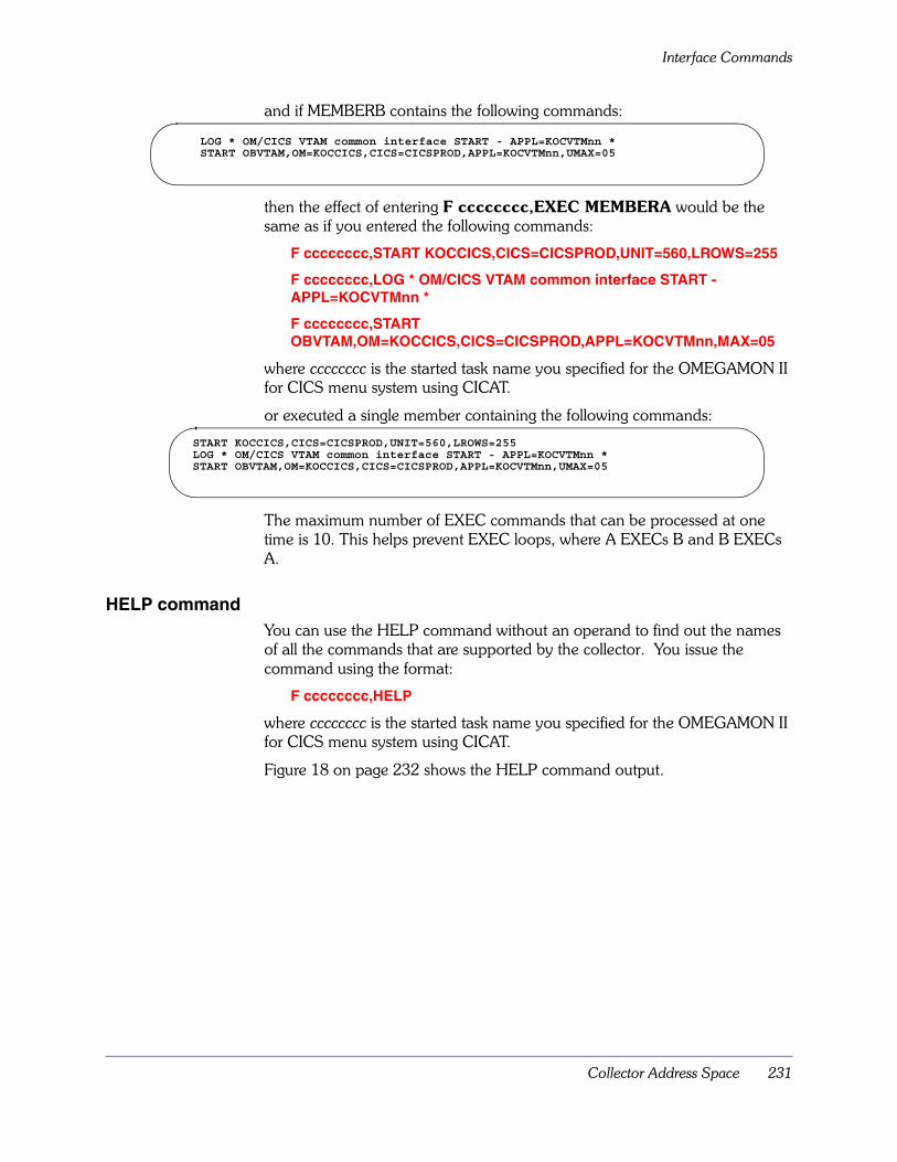
Collector Address Space 231
Interface Commands
and if MEMBERB contains the following commands:
then the effect of entering F cccccccc,EXEC MEMBERA would be the same as if you entered the following commands:
F cccccccc,START KOCCICS,CICS=CICSPROD,UNIT=560,LROWS=255
F cccccccc,LOG * OM/CICS VTAM common interface START - APPL=KOCVTMnn *
F cccccccc,START OBVTAM,OM=KOCCICS,CICS=CICSPROD,APPL=KOCVTMnn,MAX=05
where cccccccc is the started task name you specified for the OMEGAMON II for CICS menu system using CICAT.
or executed a single member containing the following commands:
The maximum number of EXEC commands that can be processed at one time is 10. This helps prevent EXEC loops, where A EXECs B and B EXECs A.
HELP commandYou can use the HELP command without an operand to find out the names of all the commands that are supported by the collector. You issue the command using the format:
F cccccccc,HELP
where cccccccc is the started task name you specified for the OMEGAMON II for CICS menu system using CICAT.
Figure 18 on page 232 shows the HELP command output.
LOG * OM/CICS VTAM common interface START - APPL=KOCVTMnn *START OBVTAM,OM=KOCCICS,CICS=CICSPROD,APPL=KOCVTMnn,UMAX=05
START KOCCICS,CICS=CICSPROD,UNIT=560,LROWS=255LOG * OM/CICS VTAM common interface START - APPL=KOCVTMnn *START OBVTAM,OM=KOCCICS,CICS=CICSPROD,APPL=KOCVTMnn,UMAX=05
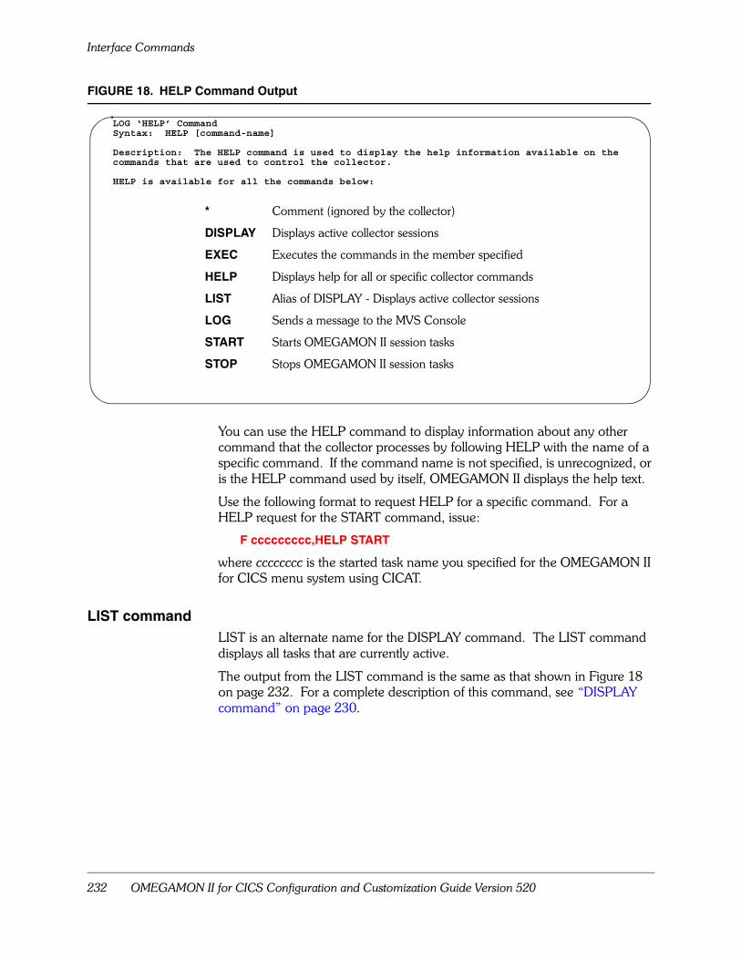
Interface Commands
232 OMEGAMON II for CICS Configuration and Customization Guide Version 520
FIGURE 18. HELP Command Output
You can use the HELP command to display information about any other command that the collector processes by following HELP with the name of a specific command. If the command name is not specified, is unrecognized, or is the HELP command used by itself, OMEGAMON II displays the help text.
Use the following format to request HELP for a specific command. For a HELP request for the START command, issue:
F ccccccccc,HELP START
where cccccccc is the started task name you specified for the OMEGAMON II for CICS menu system using CICAT.
LIST commandLIST is an alternate name for the DISPLAY command. The LIST command displays all tasks that are currently active.
The output from the LIST command is the same as that shown in Figure 18 on page 232. For a complete description of this command, see “DISPLAY command” on page 230.
LOG ‘HELP’ CommandSyntax: HELP [command-name]
Description: The HELP command is used to display the help information available on thecommands that are used to control the collector.
HELP is available for all the commands below:
* Comment (ignored by the collector)
DISPLAY Displays active collector sessions
EXEC Executes the commands in the member specified
HELP Displays help for all or specific collector commands
LIST Alias of DISPLAY - Displays active collector sessions
LOG Sends a message to the MVS Console
START Starts OMEGAMON II session tasks
STOP Stops OMEGAMON II session tasks

Collector Address Space 233
Interface Commands
LOG commandThe output from the LOG command looks exactly like its input. You can use LOG in an EXEC member to indicate the name of a command as it is being processed.
For example, if you use the LOG command to enter the following message, that message is displayed at your system console when OMEGAMON II for CICS is processing the specified member.
F cccccccc,LOG *** Processing membername ***
Where cccccccc is the started task name you specified for the OMEGAMON II for CICS menu system using CICAT.
START commandUse the START command to start a subtask under the collector. The tasks that can be started are
� OMEGAMON II dedicated sessions
� OBVTAM
� RTA
� ONDV
� DEX
� XMIT
Most of the parameters that can be specified have defaults taken from the collector or from the task being started. You can change some of these defaults by modifying the OMEGAMON II user data module.
If you stop OBVTAM, any OMEGAMON II sessions running under it also stop, and you must restart them manually.
The command to start the task history subtask from the MVS console is:
F cccccccc,START KOCBGR,CICS=cccccccc
where cccccccc is the started task name you specified for the OMEGAMON II for CICS menu system using CICAT.
A subtask may also be started by placing the START command in a member of rhilev.RKANPAR and invoking it using the EXEC command.
For examples of the START command for the internal bottleneck collector and response time collector, see rhilev.RKANSAM(KOCIDEX) and rhilev.RKANSAM(KOCIRTA).

Interface Commands
234 OMEGAMON II for CICS Configuration and Customization Guide Version 520
Use the following command to start a dedicated session: (See Table 36: START Options for OMEGAMON II and OBVTAM on page 235 for a description of the parameters.)
F cccccccc,START KOCCICS [,CICS=cccccccc]
[,COLS=nnn]
[,FSCR=cccccccc]
[,LROWS=nnn]
[,MODE=CNI]
[,ROWS=nn]
[,SYS=cccc]
[,UNIT=cuu]
[,USER=cc]
where ccccccccc is the started task name you specified for the OMEGAMON II for CICS menu system using CICAT.
Note: Changes to the FSCR parameter may disable the menu system.
An example is provided in rhilev.RKANSAM(KOCIDED).
Use the following command to start OBVTAM:
F cccccccc,START OBVTAM [,APPL=cccccccc]
[,AUP=YES/NO]
[,DATA=cc...cc]
[,LROWS=nnn]
[,MODE=IC1]
[,OM=KOCCICS]
[,PRTCT=cccccccc]
[,PSWD=cccccccc]
[,SYS=cccc]
[,UMAX=nn]
[,USER=cc]
where cccccccc is the started task name you specified for the OMEGAMON II for CICS menu system CICAT.
An example is provided in rhilev.RKANPAR(KOCVTMnn).
The application ID specified with APPL=cccccccc must be defined to VTAM. To run multiple copies of OBVTAM, use a unique applid for each copy.
The parameters specified with the START OBVTAM command become the defaults for any OMEGAMON II sessions created by OBVTAM in response to LOGON requests.
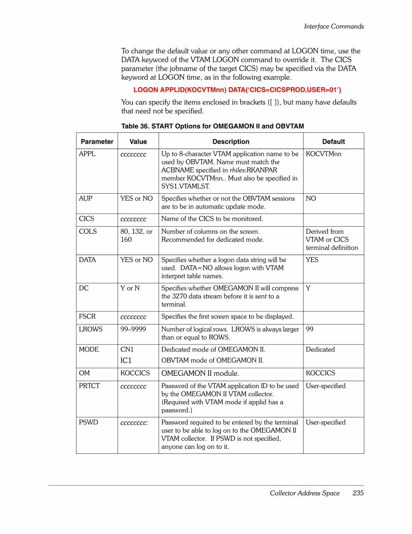
Collector Address Space 235
Interface Commands
To change the default value or any other command at LOGON time, use the DATA keyword of the VTAM LOGON command to override it. The CICS parameter (the jobname of the target CICS) may be specified via the DATA keyword at LOGON time, as in the following example.
LOGON APPLID(KOCVTMnn) DATA(‘CICS=CICSPROD,USER=01’)
You can specify the items enclosed in brackets ([ ]), but many have defaults that need not be specified.
Table 36. START Options for OMEGAMON II and OBVTAM
Parameter Value Description Default
APPL cccccccc Up to 8-character VTAM application name to be used by OBVTAM. Name must match the ACBNAME specified in rhilev.RKANPAR member KOCVTMnn.. Must also be specified in SYS1.VTAMLST.
KOCVTMnn
AUP YES or NO Specifies whether or not the OBVTAM sessions are to be in automatic update mode.
NO
CICS cccccccc Name of the CICS to be monitored.
COLS 80, 132, or 160
Number of columns on the screen. Recommended for dedicated mode.
Derived from VTAM or CICS terminal definition
DATA YES or NO Specifies whether a logon data string will be used. DATA=NO allows logon with VTAM interpret table names.
YES
DC Y or N Specifies whether OMEGAMON II will compress the 3270 data stream before it is sent to a terminal.
Y
FSCR cccccccc Specifies the first screen space to be displayed.
LROWS 99–9999 Number of logical rows. LROWS is always larger than or equal to ROWS.
99
MODE CN1
IC1
Dedicated mode of OMEGAMON II.
OBVTAM mode of OMEGAMON II.
Dedicated
OM KOCCICS OMEGAMON II module. KOCCICS
PRTCT cccccccc Password of the VTAM application ID to be used by the OMEGAMON II VTAM collector. (Required with VTAM mode if applid has a password.)
User-specified
PSWD cccccccc: Password required to be entered by the terminal user to be able to log on to the OMEGAMON II VTAM collector. If PSWD is not specified, anyone can log on to it.
User-specified

Interface Commands
236 OMEGAMON II for CICS Configuration and Customization Guide Version 520
STOP commandTo stop a collector subtask such as OBVTAM, you must specify a task ID with the STOP command. Find this ID by using the DISPLAY command (described in “DISPLAY command” on page 230), or the LIST command (described in “LIST command” on page 232).
An example of the STOP command for OBVTAM is shown below:
F ccccccccc,STOP OBVTAM
where cccccccc is the started task name you specified for the OMEGAMON II for CICS menu system using CICAT.
If you stop OBVTAM, any OMEGAMON II sessions running under it also stop.
To stop a subtask that is associated with a specific CICS region, such as KOCBGR, issue the following command specifying the fully qualified ID:
F cccccccc,STOP KOCBGR.cccccccc
where cccccccc is the started task name you specified for the OMEGAMON II for CICS menu system using CICAT.
ROWS nn Number of rows on the screen. Recommended for dedicated mode.
Derived from VTAM or CICS terminal definition
SYS cccc 4-character system ID to be displayed on the INFO-line.
sysid
TIMEOUT nn Specifies the number of minutes until OMEGAMON II terminates idle VTAM mode sessions. The value can be any number from 0 through 99. Specify 0 if you do not want VTAM mode sessions to time out.
0
UMAX 01–99 Number of sessions the OMEGAMON II VTAM collector can have. The more specified, the more storage required.
5
UNIT cuu Unit address of the OMEGAMON II terminal (used for dedicated mode).
User-specified
USER cc User profile identifier. /C
Table 36. START Options for OMEGAMON II and OBVTAM
Parameter Value Description Default
Collector Address Space 237
Installing Multiple Collector Address Spaces
Installing Multiple Collector Address SpacesIf you experience virtual storage constraints when monitoring multiple CICS address spaces, you can run additional collector address spaces.
OMEGAMON II associates each CICS address space with a particular collector when you add the following DD statement to both the JCL for the collector and the JCL for CICS:
//RKC2XMnn DD DUMMY
where nn is a 2-digit number from 00 through 15. The default is 00.
OMEGAMON II associates any CICS without an RKC2XMnn DD statement with the collector that either has no RKC2XMnn DD statement or has the RKC2XM00 DD statement.
Note: The RKC2XMnn DD statement is required only when running two or more collector address spaces of the same version number.
When installing a new version of OMEGAMON II for CICS with the existing version, you need to choose which regions are to be monitored by the new version. These regions need to have the new RKANMOD dataset in their JCL. References to the old RKANMOD dataset should be removed. Also make sure that there are no duplicate started task names or VTAM APPLIDs that conflict with the old version.
Installing Multiple Collector Address Spaces
238 OMEGAMON II for CICS Configuration and Customization Guide Version 520
Candle Standard DDnames 239
Candle Standard DDnames
Appendix Overview This appendix contains the standard DDnames for data sets.
Appendix ContentsStandard DDnames . . . . . . . . . . . . . . . . . . . . . . . . . . . . . . . . . . . . . . . . 240
B

Standard DDnames
240 OMEGAMON II for CICS Configuration and Customization Guide Version 520
Standard DDnamesThe following definitions apply to the ddnames you will find in OMEGAMON II files. They are standard throughout all Candle-supplied JCL, PROCs, and CLISTs:
RKOCPROC The datasets from which menu system screen spaces are read. A dataset in the RKOCPROC concatenation is treated as read only.
RKOCPCSV The dataset to which a site’s menu system screen spaces are written. RKOCPCSV cannot be concatenated.
RKOCPROF The datasets from which user profiles are read. A dataset in the RKOCPROF concatenation is treated as read only.
RKOCPFSV The dataset to which a site’s user profiles are written. RKOCPFSV cannot be concatenated.
RKANHENU The datasets that contain the OMEGAMON II command help panels.
RKANPAR The dataset that contains the commands to start the collector subtask.

Virtual Terminal Pool Considerations 241
Virtual Terminal Pool Considerations
Appendix OverviewThis appendix describes virtual terminal pool considerations for the menu system and the CUA interface. For the menu system it describes how to
� modify your virtual terminal pool definitions
� support OMEGAMON II sessions under more than one TSO
For the CUA interface, it describes how to increase the size of a native VTAM virtual terminal pool (non-TSO/ISPF).
Appendix ContentsModifying the Default Virtual Terminal Pool Definition . . . . . . . . . . . . . . 242Sharing Virtual Terminal Pool Definitions (Menu System) . . . . . . . . . . . . 243Increasing the Native VTAM Virtual Terminal Pool (CUA Interface) . . . . . 246
C

Modifying the Default Virtual Terminal Pool Definition
242 OMEGAMON II for CICS Configuration and Customization Guide Version 520
Modifying the Default Virtual Terminal Pool DefinitionNote: The procedure in this section applies only to the OMEGAMON II menu system.
If you use TSO or ISPF mode and your runtime environment (RTE) is not sharing libraries with other RTEs or with SMP/E, this is the procedure to modify virtual terminal pool definitions.
1. Define your virtual terminals and LOGMODE names to the VTM1 program by updating RKANSAM dataset member KOBVTPL.
2. Assemble and link the KOBVTPL source using the JCL in RKANSAM dataset member KOBVTPLX. The resulting KOBVTPL load module is stored in the RKANMOD dataset.
3. If you modified the terminal names or the number of terminals:A. Update the VTAM node list member, KOBVT1AP, in the RKANSAM
dataset.B. Update your VTAMLST controls accordingly.
Why change virtual terminal pool definitions?The default definition may require change due to any of the following conditions:
� the size of the virtual terminal pool does not meet your needs.
� the names of the virtual terminals do not meet your site’s naming conventions.
� the VTAM LOGMODE name defaults are not appropriate.
Before you make any changes to the number of virtual terminals in the pool, consider the needs of all OMEGAMON II product users running the same copy of KOBVTPL. Since virtual terminal pool definitions may be shared by multiple VTAM hosts, consider the maximum expected number of concurrent TSO and ISPF OMEGAMON II sessions as you determine the size of the virtual terminal pool.
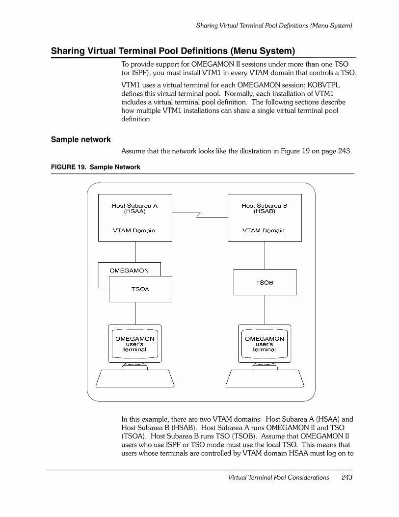
Virtual Terminal Pool Considerations 243
Sharing Virtual Terminal Pool Definitions (Menu System)
Sharing Virtual Terminal Pool Definitions (Menu System)To provide support for OMEGAMON II sessions under more than one TSO (or ISPF), you must install VTM1 in every VTAM domain that controls a TSO.
VTM1 uses a virtual terminal for each OMEGAMON session; KOBVTPL defines this virtual terminal pool. Normally, each installation of VTM1 includes a virtual terminal pool definition. The following sections describe how multiple VTM1 installations can share a single virtual terminal pool definition.
Sample networkAssume that the network looks like the illustration in Figure 19 on page 243.
FIGURE 19. Sample Network
In this example, there are two VTAM domains: Host Subarea A (HSAA) and Host Subarea B (HSAB). Host Subarea A runs OMEGAMON II and TSO (TSOA). Host Subarea B runs TSO (TSOB). Assume that OMEGAMON II users who use ISPF or TSO mode must use the local TSO. This means that users whose terminals are controlled by VTAM domain HSAA must log on to

Sharing Virtual Terminal Pool Definitions (Menu System)
244 OMEGAMON II for CICS Configuration and Customization Guide Version 520
TSOA, and users whose terminals are controlled by VTAM domain HSAB must log on to SOB.
Defining the virtual terminal pool to VTM1In the sample network described in Figure 19 on page 243, assume that a pool of 10 virtual terminals is required for each host subarea. The following $VTAPPL statement defines this virtual terminal pool to VTM1.
$VTAPPL APPL#=10,VTAPPL=OBVTM1
Specifying network names
The VTAM APPL definition statement permits you to specify a network name and an ACB name. The network name may differ from the ACB name, which may be useful in situations in which you must support multiple VTAM hosts.
Specifying ACB names
KOBVTPL defines the ACB names to VTM1, so the VTAM definitions in member KOBVT1AP must reflect these names. The $VTAPPL definition statement determines the ACB names of the virtual terminals, as follows:
� The first portion of each name (up to 6 characters) is taken from the value of the VTAPPL keyword.
� The two-character suffix is based on the value of the APPL# keyword, which may range from 01–99, inclusive.
Example
If a $VTAPPL statement is coded with VTAPPL=OBVTM1 and APPL#=25, a combination of the two keyword values results in 25 ACB names, OBVTM101 through OBVTM125.
Defining the virtual terminal pool to VTAMAfter defining virtual terminal pools to VTM1, you must define the virtual terminals to each VTAM domain. To do so, you can define the local name and the network name separately.
� the local name is defined by the ACBNAME keyword in the VTAM APPL definition statement
� the network name is defined by the name field in the VTAM APPL definition statement. In the sample VTAM APPL definitions that follow, the HSAA network names differ from those of HSAB, but the local names for each virtual terminal are the same in both host subareas.
Figure 20 on page 245 shows the definition statements for Host Subarea A that correspond to the $VTAPPL definition statement.

Virtual Terminal Pool Considerations 245
Sharing Virtual Terminal Pool Definitions (Menu System)
FIGURE 20. HSAA VTAM Definition Statements
Figure 21 on page 245 shows the definition statements for Host Subarea B that correspond to the $VTAPPL definition statement.
FIGURE 21. HSAB VTAM Definition Statements
Virtual terminal pool access summaryVTM1 selects virtual terminals from KOBVTPL at run time when an OMEGAMON II session in TSO or ISPF modes is started. Any changes you make to the default KOBVTPL must be assembled and link-edited.
Install VTM1 execution-time modules–including KOBVTPL– in both host subareas. The most convenient method is to place these modules in a load library shared by both systems. This will allow TSOA and TSOB users access to OMEGAMON II.
HSAAVTM1 VBUILD TYPE=APPLHSAAVT01 APPL ACBNAME=OBVTM101,EAS=1HSAAVT02 APPL ACBNAME=OBVTM102,EAS=1HSAAVT03 APPL ACBNAME=OBVTM103,EAS=1HSAAVT04 APPL ACBNAME=OBVTM104,EAS=1HSAAVT05 APPL ACBNAME=OBVTM105,EAS=1HSAAVT06 APPL ACBNAME=OBVTM106,EAS=1HSAAVT07 APPL ACBNAME=OBVTM107,EAS=1HSAAVT08 APPL ACBNAME=OBVTM108,EAS=1HSAAVT09 APPL ACBNAME=OBVTM109,EAS=1HSAAVT10 APPL ACBNAME=OBVTM110,EAS=1
HSABVTM1 VBUILD TYPE=APPLHSABVT01 APPL ACBNAME=OBVTM101,EAS=1HSABVT02 APPL ACBNAME=OBVTM102,EAS=1HSABVT03 APPL ACBNAME=OBVTM103,EAS=1HSABVT04 APPL ACBNAME=OBVTM104,EAS=1HSABVT05 APPL ACBNAME=OBVTM105,EAS=1HSABVT06 APPL ACBNAME=OBVTM106,EAS=1HSABVT07 APPL ACBNAME=OBVTM107,EAS=1HSABVT08 APPL ACBNAME=OBVTM108,EAS=1HSABVT09 APPL ACBNAME=OBVTM109,EAS=1HSABVT10 APPL ACBNAME=OBVTM110,EAS=1

Increasing the Native VTAM Virtual Terminal Pool (CUA Interface)
246 OMEGAMON II for CICS Configuration and Customization Guide Version 520
Increasing the Native VTAM Virtual Terminal Pool (CUA Interface)The CUA interface utilizes virtual terminals to access the collector. Normally, the number of sessions is specified during CICAT configuration.
This section provides instructions for manually changing the number of native VTAM (non-TSO/ISPF) virtual terminals available to the CUA, if, for any reason, the CICAT is not available.
Defined virtual terminal poolsVirtual terminal pools are defined to
� the OMEGAMON II for CICS CUA interface with the VSM command
� the network in SYS1.VTAMLST application major nodes
Note: The virtual terminals in the pool are defined in SYS1.VTAMLST application major nodes.

Virtual Terminal Pool Considerations 247
Increasing the Native VTAM Virtual Terminal Pool (CUA Interface)
Adding to a virtual terminal poolTo add to a virtual terminal pool, follow this procedure:
1. Add the new terminals to the network definition in SYS1.VTAMLST newname For example:
termname APPL AUTH=(ACQ,NVPACE),EAS=1,ACBNAME=termname
For virtual terminal applications that support parallel sessions, specify PARSESS=YES instead of EAS=1.
2. To add terminals, you can either modify the VSM command in member C2STAnn of your commands library or issue the command through the CL/ENGINE operator facility.For example, if the terminal definitions for the pool $DEFAULT are
VSM DEFINE $DEFAULT KC20001 THROUGH(10)
and you want to add 10 terminals, change the VSM DEFINE statement in KC2STAnn to:
VSM DEFINE $DEFAULT KC20001 THROUGH(20)
3. Restart theOMEGAMON II for CICS CUA interface task to initialize your new virtual terminal pool definitions.
To add virtual terminals dynamically, issue the following command through the CL/ENGINE operator facility:
VSM DEFINE poolname termname THROUGH(nnn)
When you dynamically define terminals to the same terminal pool, you are adding on to the terminals defined by KC2ST nn at startup, not replacing the existing definition.
Note: When you issue the VSM DEFINE command dynamically, your new terminal definitions are temporary; they are not saved when you shutdown and restart the OMEGAMON II for CICS CUA interface task. If you want to save your new definitions, you must change the KC2STAnn member in your commands library.

Increasing the Native VTAM Virtual Terminal Pool (CUA Interface)
248 OMEGAMON II for CICS Configuration and Customization Guide Version 520
CT/Engine initialization and Customization Parameters 249
CT/Engine initialization andCustomization Parameters
Appendix OverviewThe CT/Engine component drives the CUA interface. This appendix contains CT/Engine initialization and customization parameters.
MINIMUM, MAXIMUM, and LIMIT parameters are required for OMEGAMON II. The other parameters appear here for your information only. Candle does not recommend that you modify them.
Appendix ContentsCT/Engine Startup Parameters . . . . . . . . . . . . . . . . . . . . . . . . . . . . . . . . 250
D

CT/Engine Startup Parameters
250 OMEGAMON II for CICS Configuration and Customization Guide Version 520
CT/Engine Startup ParametersThe CUA interface startup parameters are defined with appropriate defaults in member KC2SYSnn of RKANPAR. CT/Engine startup parameters specify the execution and resource management environment.
You may override certain CT/Engine operating parameters at initialization time by coding the parameters in KC2SYSnn or the EXEC PARM field of the JCL. JCL specification PARMs override KC2SYSnn parameters.
AMODE31AMODE31(Y|N)
Determines whether CT/Engine runs in 31-bit addressing mode. Y is the default for MVS/XA and MVS/ESA. N is the default for MVS/SP.
If MVS/XA is running under VTAM prior to Version 3.1.1 or DFP prior to Version 1.2, code the following:
AMODE31(N)
APFAPF(Y|N)
Determines whether CT/Engine runs as APF-authorized. Y is the default if the CT/Engine job step is APF-authorized; otherwise, N is the default.
Note: If you specify Y, the CT/Engine job step must be APF-authorized.
CONFIRMCONFIRM(n)
Default is CONFIRM(15).
Sets the maximum number of seconds between two successive SHUTDOWN commands or MVS STOP (P) commands to terminate the CT/Engine address space.
CONFIRM(0) allows immediate shutdown. CONFIRM(n) prevents accidental shutdowns by requiring you to confirm the command by entering it a second time within the specified number of seconds.
For example, the default (15) requires you enter SHUTDOWN twice within 15 seconds to terminate the CT/Engine address space.
DATEFMTDATEFMT([mmddyy|ddmmyy|yymmdd)
CT/Engine initialization and Customization Parameters 251
CT/Engine Startup Parameters
Specifies the format of dates displayed by CT/Engine. Possible values are
DEBUGDEBUG(Y|N)
Specify Y to use the debug option for resolving internal problems.
DEBUG(Y) automatically turns on the internal trace with the default number of entries (1024). DEBUG(Y) can affect CT/Engine performance adversely by increasing storage use.
FRAMEFRAME(n)
Default is FRAME(512).
Specifies the size, in bytes, of a save area stack. CT/Engine preallocates a contiguous area of extended storage that is used as a stack. When a module is called, a portion of the stack is used for the module’s save area and local working storage. If the area fills up, CT/Engine allocates another save area stack. Specifying larger FRAME values enable you to
� produce larger preallocated save area stacks
� avoid dynamic GET and FREE overhead
� leave some storage idle
FRAME(1) turns off all preallocation. In general, FRAME(180) conserves virtual storage without unduly affecting performance. FRAME(900) is the largest useful value.
INBDLIMINBDLIM(n)
Default is INBDLIM(25).
Specifies the maximum number of messages that can be queued for a session between an application and CT/Engine. If this number is exceeded, the session terminates.
INBDLIM prevents applications from flooding CT/Engine with messages, which causes CT/Engine to run short of storage and abend. By specifying a large value, an application that sends many outbound datastreams to a terminal without requesting input can cause CT/Engine to abend, even if definite response is not specified for the session.
mmddyy U.S. format (default)
ddmmyy European format
yymmdd International format
CT/Engine Startup Parameters
252 OMEGAMON II for CICS Configuration and Customization Guide Version 520
Most file transfer programs implement handshaking protocols that require them to perform read operations. These programs should not be affected by a small INBDLIM value.
Note: INBDLIM limits the number of messages an application sends to CT/Engine (the virtual terminal). OUTBDLIM limits the number of messages CT/Engine sends to the physical terminal.
INBOUNDINBOUND(n)
Default is INBOUND(248).
Specifies the size of all VTAM RECEIVE buffers, regardless of origin.
If the length of a received RU is larger than the value assigned to INBOUND, excess path lengths result. If the value assigned to INBOUND is much larger than the length of the RUs received, storage problems may result.
If you are running above VTAM 1.3, do not modify the INBOUND parameter.
INITIALINITIAL(membername)
Identifies the command list (CLIST) that contains CT/Engine initialization commands. There is no hard-coded default. RKANPAR(KC2SYSnn) contains INITIAL(KC2STAnn), which invokes the KC2STAnn member of RKANCMD.
RKANPAR may contain a member named $smfid, where smfid is the SMF ID of the CPU executing CT/Engine. If this member exists, it is automatically invoked before the command list specified in the INITIAL parameter.
INTLCHARINTLCHAR(Y)
Implements the following national language support features:
1. The window vertical bar character (|) is changed from X’6AX’ to X ‘4F’.
2. Characters with diacritical marks that were previously interpreted as invalid are now valid.
LIMITLIMIT(n,P|X)
Default is LIMIT(16,P).
Builds storage access tables to speed memory allocation. The variable n represents the largest block of primary or extended storage that can be allocated. This value is specified in bytes, as a power of 2. For example, if n is 16, the largest block that can be allocated is 65,536 bytes.

CT/Engine initialization and Customization Parameters 253
CT/Engine Startup Parameters
X stands for extended storage, and P stands for primary storage. Primary storage is below the 16-megabyte line; extended storage is above the line. To specify values for both primary and extended storage, include the LIMIT parameter twice in KC2SYSnn:
LIMIT(n,X)
LIMIT(n,P)
If the LIMIT value is too small and a process in CT/Engine attempts to allocate a block of storage larger than LIMIT specifies, program interruption U0100 or U0200 results. Too large a LIMIT value may waste storage and increase processing overhead.
LOGBLOCKLOGBLOCK(n)
Default is LOGBLOCK(3120).
Specifies, in bytes, the block size of the CT/Engine LOG file.
LOGBUFSLOGBUFS(n)
Default is LOGBUFS(2). Specifies the number of buffers to allocate for the CT/Engine LOG file.
If the value of LOGBUFS is small and extensive logging is performed (for example, during debugging), CT/Engine response may suffer because of excessive physical I/O. If the value of LOGBUFS is large, storage shortages may occur.
LSRPOOLLSRPOOL(m,n,hiper)
No default for m and n; the default for hiper is 0. You must code at least one LSRPOOL parameter in order for CT/Engine to start.
Corresponds to the BUFFERS parameter of the BLDVRP macro instruction, and specifies the number of buffers to be made available for each VSAM dataset used by CT/Engine. CT/Engine selects the optimal size buffer from the pool for each VSAM dataset. The variable m represents the size of each buffer, n represents the number of buffers of that size in the pool, and hiper represents the size of hiperspace buffers VSAM needs to create.
Valid buffer sizes are 512, 1024, 2048, 4096, 8192, 12288, 16384, 20480, 24576, 28672, and 32768.
The minimum number of buffers of each size is 3. There is no maximum number of buffers, other than the amount of available virtual storage in the CT/Engine address space.
CT/Engine Startup Parameters
254 OMEGAMON II for CICS Configuration and Customization Guide Version 520
Valid hiperspace buffer sizes are 0 to 16777215. IBM restricts hiperspace buffers to multiples of 4K. If you use buffer size 512, 1024, or 2048, CT/Engine will issue an error message and terminate startup. Refer to the IBM DFP manual Using Data Sets for more information about hiperspace buffers.
For best storage use, code an LSRPOOL parameter for each different VSAM control interval size that CT/Engine uses:
� index component for NAM and table database
� data component for NAM and table database
� data component for VIEWLOG
To obtain the control interval size (CISIZE) for each component, perform there steps:
1. Run IDCAMS.
2. Issue a LISTCAT ALL command for each VSAM dataset.
3. Search for the CISIZE for each component.Because many different Candle products can run on CT/Engine, Candle recommends that you always code an LSRPOOL value for the 32768 buffer size. This ensures that buffers are available for any product-specific dataset in use. Candle distributes the recommended values in RKANPAR(KC2SYSnn).
Note: You must enter LSRPOOLs individually; you cannot string them.
Refer to the additional guidelines below before coding the LSRPOOL parameter.
� LSR pools are allocated from MVS storage and will honor the AMODE31 specifications.
� VSAM hiperspace buffers require MVS/DFP 3.1.0 or higher.
� VSAM requires 32 bytes in the CT/Engine address space for each hiperspace buffer. This storage follows AMODE31.
� If you are using hiperspace buffers, ensure that the CT/Engine address space is non-swappable (see the SWAP parameter). All hiperspace buffers are invalidated if CT/Engine swaps out.
� If you receive many KLVVS026 messages identifying buffer contention, increase the number of buffers allocated to the dataset identified in the associated KLVVS021 messages.
LSRSTRNOLSRSTRNO(n)
Default is LSRSTRNO(32).
CT/Engine initialization and Customization Parameters 255
CT/Engine Startup Parameters
Corresponds to the STRNO parameter of the BLDVRP macro instruction. It is the maximum number of concurrent VSAM requests that CT/Engine can process against all the VSAM datasets allocated to it.
If you receive many KLVVS026 messages identifying string contention, or if the STRMAX value in the KLVVS002 messages issued during CT/Engine shutdown is consistently the same as the value in KC2SYSnn, increase the LSRSTRNO value.
The minimum value is 1. The maximum is 255.
MAXIMUMMAXIMUM(n,P|X)
Default is MAXIMUM(8192,P); but if you specify X, default is the value specified by the MINIMUM parameter.
MAXIMUM is a storage throttle used to prevent GETMAINs from overallocating and occupying the page dataset with rarely referenced frames.
The variable n represents the maximum amount (in kilobytes) of primary or extended storage that can be allocated. X stands for extended storage, and P stands for primary storage. Primary storage is below the 16-megabyte line; extended storage is above the line.
Set your MAXIMUM value to a value that will allow CT/Engine to continue running without overloading your page volumes when the steady-state MINIMUM value is exceeded.
To use extended storage, you must do both of the following:
� Code the MINIMUM parameter.
� Make sure that MAXIMUM is equal to or greater than MINIMUM + RESERVE.
If MAXIMUM is too large and RESERVE is not large enough to meet your requirements, the address space may run out of virtual storage.
If the value of MAXIMUM is greater than that of MINIMUM, CT/Engine attempts a conditional GETMAIN for the MAXIMUM value minus the RESERVE value (RESERVE defaults to 512,P.). If the MAXIMUM value is not satisfied, CT/Engine accepts the amount of storage acquired by the GETMAIN.
MINIMUMMINIMUM(n,P|X)
Default is MINIMUM(1024,P); but if you specify X, default is 0.
The variable n represents the mimimum amount (in kilobytes) of primary or extended storage that can be allocated.
For example, to specify a 16-megabyte above-the-line region, code

CT/Engine Startup Parameters
256 OMEGAMON II for CICS Configuration and Customization Guide Version 520
MINIMUM(16364,X)
To specify a 32-megabyte above-the-line region, code
MINIMUM(32768,X)
To use extended storage, you must do both of the following:
� Code the MINIMUM parameter.
� Make sure that MINIMUM + RESERVE is less than or equal to MAXIMUM.
Note the following about the default above-the-line region:
� Specified in the IEFUSI and IEALIMIT MVS modules.
� Distributed by IBM as 32 megabytes.
� If smaller than the amount specified for the MINIMUM parameter, do one of the following:
– Alter the default.
– Use the REGION parameter as follows:
In general, Candle recommends REGION=0M.
OPLIMITOPLIMIT(n)
Specifies the maximum number of characters that can be queued to a single CT/Engine operator before the messages are bypassed. The default is no limit.
OPLOCALOPLOCAL(messagetype,messagetype,...)
Default is OPLOCAL(REPLY,ERROR).
Specifies the types of messages an operator console receives in response to actions initiated by that same console.
With the default OPLOCAL setting, an operator performing an action that generates a CT/Engine ALERT message does not receive the message at the console unless OPMASK allows it. For information on message types, see OMEGAMON II for CICS Messages Manual.
0K or 0M All primary and extended storage is available for GETMAIN.
Up to 16M Primary region equals the specified value; extended region equals the default.
Up to 32M All available region goes to primary storage; extended region equals the default.
Above 32M All available region goes to primary storage; specified value goes to extended storage.
CT/Engine initialization and Customization Parameters 257
CT/Engine Startup Parameters
OPMASKOPMASK(messagetype,messagetype,...)
Default is OPMASK(INFO,WARN,ALERT).
Specifies the types of unsolicited messages all operator consoles receive. For information on message types, see OMEGAMON II for CICS Messages Manual.
OPSTARTOPSTART(command)
Specifies an initial CT/Engine command or CLIST to be issued after an operator logs on. There is no hard-coded default. RKANPAR(KC2SYSnn)contains OPSTART(KC2OPSnn), which invokes the KC2OPSnn member of RKANCMD.
OUTBDLIMOUTBDLIM(n)
Default is OUTBDLIM(500).
Specifies the maximum number of messages that can be queued for a session between CT/Engine and the physical terminal. If this number is exceeded, the session terminates.
The purpose of OUTBDLIM is to prevent excessive messages from causing CT/Engine to run short of storage and abend. If you specify a very large value for OUTBDLIM, an application that sends many outbound datastreams to a terminal without requesting input can cause CT/Engine to abend, even if definite response is not specified for the session.
Note: OUTBDLIM limits the number of messages CT/Engine sends to the physical terminal. INBDLIM limits the number of messages an application sends to CT/Engine (the virtual terminal).
OUTBOUNDOUTBOUND(n)
Default is OUTBOUND(504).
Specifies, in bytes, an outbound RU buffer length for VTAM sessions for which a length is not provided in the session parameters.
PACK PACK(Y|N)
Determines how CT/Engine loads modules into the CT/Engine region. The default, PACK(Y), specifies that CT/Engine relocates the load module into the next lowest available primary storage location. PACK(Y) indicates that an
CT/Engine Startup Parameters
258 OMEGAMON II for CICS Configuration and Customization Guide Version 520
MVS load of the module will be used. This means MVS puts the load module at the next available free storage area that is able to hold the entire module. A contents directory element (CDE), which identifies resident load modules, allows TSO TEST, INSPECT, or any other MVS-based function to find the load module.
Note: When PACK(Y) is specified, an MVS directed load is used instead of the CT/Engine relocator when running APF-authorized.
QUIESCE QUIESCE(n,P|X,F|C)
Sets thresholds for slowing down allocation of storage. When the thresholds are exceeded, quiesce mode goes into effect, causing rejection of all conditional storage requests. Conditional storage requests include session and dialog startup, as well as other functions that can recover from a storage shortage. Unconditional requests for storage continue to be satisfied in quiesce mode.
The variable n represents the percentage of primary (P) or extended (X), free (F) or carved (C) storage allowed to be allocated before quiesce mode takes effect. Carved storage is storage put into use for the first time and allocated to a specific size; free storage is storage that has been carved but is not in use. Primary storage is below the 16-megabyte line; extended storage is above the line.
A value of zero (0) indicates no QUIESCE threshold, which means quiesce mode never goes into effect. A value of 100 indicates that all storage must be used or carved before quiesce mode takes effect.
There is one default for each of the possible combinations of the storage types:
QUIESCE(90,P,F)
QUIESCE(95,P,C)
QUIESCE(90,X,F)
QUIESCE(95,X,C)
To specify that quiesce mode takes effect when 80% of the total amount of storage is in use in extended storage, enter the following:
QUIESCE(80,X,F)
To specify that quiesce mode takes effect when 90% of the total amount of primary storage has been carved, enter the following:
QUIESCE(90,P,C)
When CT/Engine detects that the amount of storage carved or in use is above the QUIESCE threshold percentage, it enters quiesce mode and does not permit new dialogs or sessions to start. For free storage, quiesce mode

CT/Engine initialization and Customization Parameters 259
CT/Engine Startup Parameters
continues until the amount of storage in use drops below a recovery point, calculated as follows:
Recovery point = Threshold amount - ((MAXIMUM - Threshold amount) / 2)
For example, with a MAXIMUM of 10 megabytes and a QUIESCE value of 90:
Recovery point = 9M - ((10M - 9M) / 2) = 8.5M
For carved storage, quiesce mode has no recovery point. Until CT/Engine is recycled, no new sessions or dialogs can be started. However, existing sessions and dialogs continue to operate normally.
You can use the STGMON parameter to control reporting on quiesce mode conditions. See “STGMON” on page 260.
RESERVERESERVE(n,P|X)
The variable n represents the number of kilobytes of primary (P) or extended (X) storage to set aside for other routines that may perform their own GETMAINs in the CT/Engine address space (for example, ACF2 and RACF). The default for primary storage (P) is 512. The default for extended storage (X) is 2048. Primary storage is below the 16-megabyte line, and extended storage is above the line.
To specify values for both primary and extended storage, include the RESERVE parameter twice in KC2SYSnn:
RESERVE(n,X)
RESERVE(n,P)
If the RESERVE value is larger than the MINIMUM value, CT/Engine terminates. The total of the MINIMUM and RESERVE values must be less than or equal to the MAXIMUM value.
If you have ACF2 or RACF installed, the default setting (512,P) supports about 500 users. ACF2 and RACF use approximately 1K of primary storage per logged-on user. If your RESERVE value is too small, you may encounter IST566I messages from VTAM or S80A, S878, S066, S40D, or S0F9 abends.
SDUMPSDUMP(Y|N)
Determines whether or not SVC dumps are generated. If the CT/Engine job step is APF-authorized, the default is Y. Otherwise, the default is N, and you must APF-authorize the CT/Engine job step before you can specify SDUMP(Y).
To capture an entire SVC dump, perform these steps:

CT/Engine Startup Parameters
260 OMEGAMON II for CICS Configuration and Customization Guide Version 520
1. Ensure that the SYS1.DUMPxx datasets are large enough to hold the contents of the CT/Engine address space.
2. Determine the size of the CT/Engine address space.
3. Provide enough DASD in the SYS1.DUMPxx datasets to accommodate the SDUMP requirements.For MVS/ESA 3.1.3 and higher, SDUMP writes an unblocked 4160-byte record for each page of virtual storage being dumped. For earlier versions of MVS, the record size is 4104 bytes.
Candle recommends these storage guidelines for SVC DUMP datasets:
� Allocate 32 meg if 16 to 32 meg are specified in KC2SYSnn for MINIMUM/MAXIMUM keywords.
� For each additional 16 meg specified in KC2SYSnn for MINIMUM/MAXIMUM keywords, add 25 meg for the SVC DUMP dataset.
For example:
MINIMUM (16384,x) - Allocate a 32 meg SVC DUMP dataset
MINIMUM (32768,x) - Allocate a 57 meg SVC DUMP dataset
MINIMUM (49152,x) - Allocate a 82 meg SVC DUMP dataset
MINIMUM (65536,x) - Allocate a 107 meg SVC DUMP dataset
STGMONSTGMON(n)
Default is STGMON(15).
Specifies the number of minutes between storage quiesce mode message displays. Any value from 0 through 120 is valid. A value of 0 results in messages being issued only when a short-on-storage condition is detected or relieved (for example, when the quiesce mode state changes).
SWAP SWAP(N|Y)
Specifies whether the CT/Engine job step is APF-authorized and the CT/Engine region is swappable. The default is N if the CT/Engine job step is APF-authorized. Otherwise, it is Y.
TASKSTASKS(n|number of processors available)
Default is TASKS(number of available processors).
Specifies the number of general-purpose subtasks to be attached in the CT/Engine address space. If CT/Engine is running on a multiprocessor, the

CT/Engine initialization and Customization Parameters 261
CT/Engine Startup Parameters
TASKS default increases both throughput and CPU usage. Reducing the number of tasks decreases both throughput and CPU usage.
In general, reduce the value of TASKS only when CPU usage is a concern and system paging is low, since fewer tasks will be available for performing work whenever other tasks are in a page-fault wait.
TRACETRACE(n)
Default is TRACE(10).
Specifies, as the exponent of a power of 2, the number of trace table entries to reserve. Each entry consists of 32 bytes. The default (10) reserves 1024 trace entries. The trace table is allocated only if DEBUG is set to Y.
Specifying too small a TRACE value results in the loss of diagnostic information. Too large a value may cause storage problems.
UPPERDLGUPPERDLG(Y|N)
Determines whether or not SSPL dialog output is folded to upper case before displaying on users’ terminals. UPPERDLG(N) is the default.
WTOWTO(Y|N)
Determines whether or not CT/Engine issues WTOs. WTO(Y) is the default.
WTOs write information and exception condition messages to the operator consoles. ALERT messages are always written to the consoles.
WTODCWTODC(type,code,code,...)
Default is WTODC(ALERT2).
Specifies WTO descriptor codes for CT/Engine messages.
Specify one WTODC parameter for each CT/Engine message type. For example, to assign descriptor code 7 (Application Program/Processor) to CT/Engine error messages, enter the following:
WTODC(ERROR,7)
For definitions of the descriptor codes, see IBM’s Supervisor Services and Macro Instructions manual. For information on message types, see the OMEGAMON II for CICS Messages Manual.

CT/Engine Startup Parameters
262 OMEGAMON II for CICS Configuration and Customization Guide Version 520
WTORCWTORC(type,code,code,...)
Default is WTORC(ALERT,1,8,11).
Specifies WTO route codes for CT/Engine messages. Specify the WTORC parameter for each CT/Engine message type.
For definitions of the route codes, see IBM’s Supervisor Services and Macro Instructions manual. For information on message types, see the OMEGAMON II for CICS Messages Manual.
Modifying the JES2 Offset Table (If Required) 263
Modifying the JES2 OffsetTable (If Required)
Appendix OverviewThis appendix contains information about the steps required to modify the JES2 offset table.
Appendix ContentsModifying the JES2 Offset Table . . . . . . . . . . . . . . . . . . . . . . . . . . . . . . . 264
E

Modifying the JES2 Offset Table
264 OMEGAMON II for CICS Configuration and Customization Guide Version 520
Modifying the JES2 Offset Table If you have modified internal JES2 DSECTS, you must submit a job that reassembles the JES2 offset table and does an SMP/E APPLY of the new table as a USERMOD. To do this, follow these steps:
1. Copy member thilev.TKANSAM(KC2UJES2) to a runtime library.
2. Edit member KC2UJES2 in the runtime library.
3. Change the jobcard for your site.
4. Follow the instructions contained in the member.
5. Be sure the SYSLIB concatenation in the first step of the job exactly matches the concatenation you used when JES2 was last assembled.
6. Submit this job and review the output for successful completion.If you have applied QJIxxxx maintenance, you may get a MODID error from the SMP/E APPLY of the USERMOD . This is a normal occurrence, since the USERMOD does not PRE or SUP any JES2 Interface maintenance. Therefore, you may specify BYPASS(MODID) to apply the USERMOD.

Customer Support 265
Customer Support
Introduction Candle Corporation offers a comprehensive maintenance and support plan to ensure you realize the greatest value possible from your Candle software investments. We have more than 200 technicians worldwide, committed to providing you with prompt resolutions to your support requests.
Customer Support hours of operation are from 5:30 A.M. – 5:00 P.M., Pacific Time. In the event of an after-hours or weekend emergency, Candle's computerized call management system ensures that a technician will return your call within one hour. For customers located outside of North America, after-hours and weekend support is provided by Candle Customer Support locations in the United States.
Electronic supportCandle provides information and support services through
� Candle's home page at www.candle.com. You can use the Candle Worldwide Web Site to
– open problem records
– access maintenance information
– order products or maintenance
– access IBM compatibility information
– download fix packs for distributed products
– read news and alerts
– scan a list of scheduled Candle education classes
� Candle Electronic Customer Support (CECS), an electronic customer support facility. You can access this facility using the IBM Global Network. You can use CECS to:
– open problem records
– search our database for solutions to known problems
– look for answers to commonly asked questions
– read news and alerts
F
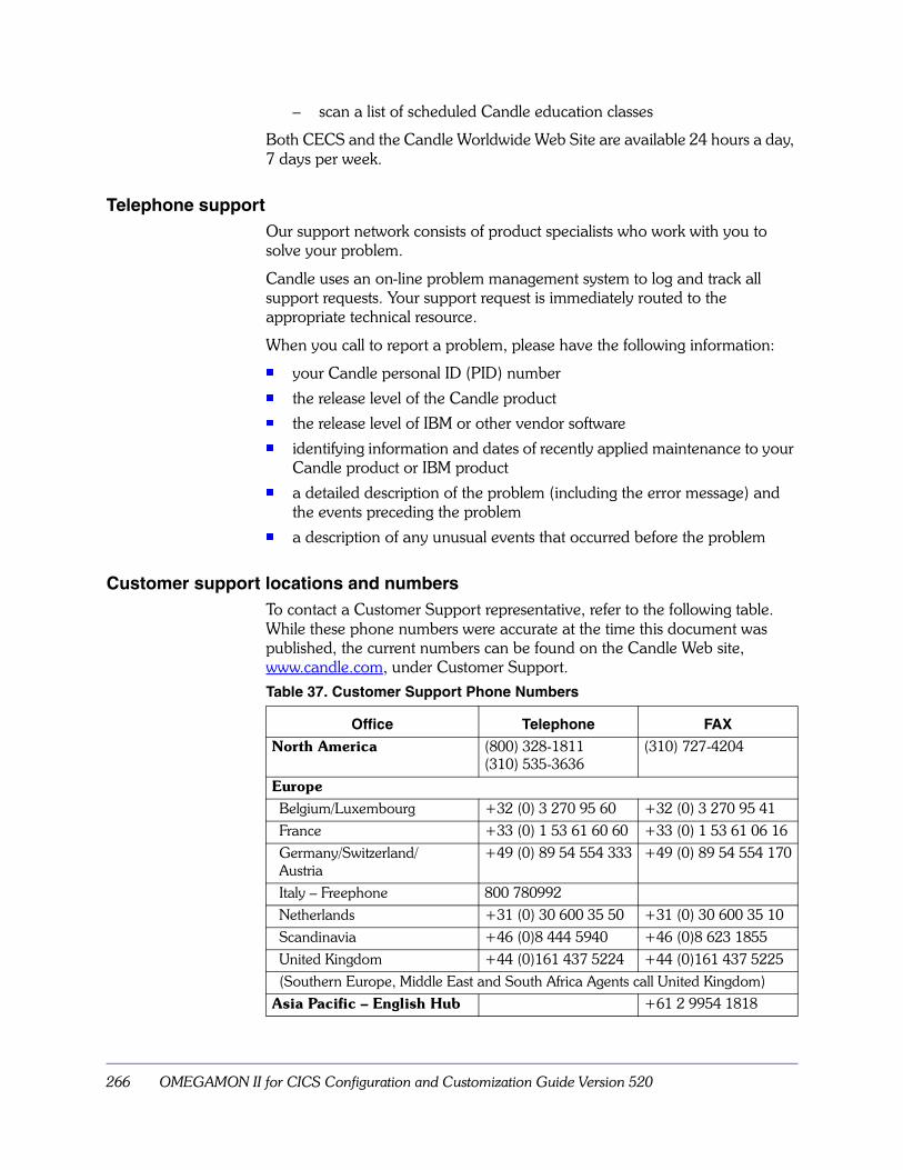
266 OMEGAMON II for CICS Configuration and Customization Guide Version 520
– scan a list of scheduled Candle education classes
Both CECS and the Candle Worldwide Web Site are available 24 hours a day, 7 days per week.
Telephone supportOur support network consists of product specialists who work with you to solve your problem.
Candle uses an on-line problem management system to log and track all support requests. Your support request is immediately routed to the appropriate technical resource.
When you call to report a problem, please have the following information:
� your Candle personal ID (PID) number� the release level of the Candle product � the release level of IBM or other vendor software � identifying information and dates of recently applied maintenance to your
Candle product or IBM product� a detailed description of the problem (including the error message) and
the events preceding the problem� a description of any unusual events that occurred before the problem
Customer support locations and numbersTo contact a Customer Support representative, refer to the following table. While these phone numbers were accurate at the time this document was published, the current numbers can be found on the Candle Web site, www.candle.com, under Customer Support.Table 37. Customer Support Phone Numbers
Office Telephone FAX
North America (800) 328-1811 (310) 535-3636
(310) 727-4204
EuropeBelgium/Luxembourg +32 (0) 3 270 95 60 +32 (0) 3 270 95 41France +33 (0) 1 53 61 60 60 +33 (0) 1 53 61 06 16Germany/Switzerland/Austria
+49 (0) 89 54 554 333 +49 (0) 89 54 554 170
Italy – Freephone 800 780992Netherlands +31 (0) 30 600 35 50 +31 (0) 30 600 35 10Scandinavia +46 (0)8 444 5940 +46 (0)8 623 1855United Kingdom +44 (0)161 437 5224 +44 (0)161 437 5225(Southern Europe, Middle East and South Africa Agents call United Kingdom)
Asia Pacific – English Hub +61 2 9954 1818

Customer Support 267
When your local support office is unavailable, you can contact Candle's North America support center. If USADirect® service is available in your country, use the 800 telephone number. If USADirect® service is not available, ask your international operator for assistance in calling Candle's local (310) number.
Australia +61 2 8912 9898Hong Kong 800 908 457India +61 2 8912 9898Indonesia 0018 03061 2061Malaysia 1800 803 459New Zealand 0800 449 596Philippines 1800 1612 0096Singapore 800 616 2075Thailand 0018 00612 1045
Asia Pacific – Japanese Hub +81 3 3595 7150 +81 3 3595 7110Asia Pacific – Korean Hub +82 2 552 8744 +82 2 552 8746Asia Pacific – Mandarin Hub +88 62 2739 3223 +88 62 2378 5993Asia Pacific – e-mail address: [email protected]
Table 37. Customer Support Phone Numbers (continued)
Office Telephone FAX
268 OMEGAMON II for CICS Configuration and Customization Guide Version 520
Incident documentationYou may be asked to send incident documentation to the Candle Customer Support Center. On the outside of all packages you send, please write the incident number given to you by the Customer Support representative.
Send tapes containing the incident information to the following address, unless directed otherwise by your Customer Support representative:
Candle Customer SupportCandle Support Center, Incident number201 North Douglas StreetEl Segundo, California 90245
Send all other relevant documentation, such as diskettes or paper documentation, to the address provided by your Customer Support representative.
Ensuring your satisfaction with customer supportCandle Customer Support is committed to achieving high customer satisfaction ratings in all areas. These include
� connecting you to a support representative promptly
� providing you with the appropriate fixes
� answering support questions
� filling your shipping orders
� supplying documentation
If you have a concern that has not been resolved to your satisfaction, you can open a complaint ticket. All tickets are logged and tracked to ensure responsiveness and closure. Using the ticket information, a manager will contact you promptly to resolve your problem.

269
270 OMEGAMON II for CICS Configuration and Customization Guide Version 520

Index 271
Symbols$UCHECK macro 173/PWD command 162, 163, 165, 181, 183
relogon feature 168
Aabend, FFF 119activating 51ADABAS
installing support 210Adobe portable document format 14AMODE31, KC2SYSnn parameter 250APF authorization 181
for VTAM mode 167APF, KC2SYSnn parameter 250application
OBVTAM 57VTM1 57
asterisk (*)collector comment
comment (*) 229comment line 179disabled commands 190
ATTN key 163audit 181
CA-ACF2 ACFRPT 193RACF Report Writer 193security 192supplemental 193suppression 193WTO 181
AUDIT keyword 181AUTHLIB control satements 180AUTHLIB control statements 179authorization
considerations 44authorized commands 162
access 163removing access 163
authorized screen library 177, 179
Bbottleneck analysis 29
CCA-ACF2 32
auditing 193defining OMEGAMON II to 170for CUA interface 131locking facility 166macro library 171resource class 171restricting a command 171rule compiler 171security 173
CA-DATACOMinstalling support 211
CA-IDEALcalling
conventions 173flow 175
Candle Electronic Customer Support (CECS) 265Candle home page 265Candle Installation Configuration Assistance Tool
(CICAT) 80Candle Internet site 265Candle Subsystem
verifying 51Candle Worldwide Web site 265Candle-supplied profile 146carved storage 258CA-TOP SECRET
CUA interface 133locking facility 166
CEDA transactionOMEG transaction
KOCOME00 program 73, 75CICAT 35
help 33CICS monitoring facility (CMF) 204CICS parameter in KOCLIST 59CICS Region panel
regions listed 29CICS Regions panel considerations 29CLIST
ISPF 58TSO 58
CMF monitoring possibilities 100collector 227
commands 229EXEC 62
defined (Started task for menu system 16logon in VTAM mode 110
Index

272 OMEGAMON II for CICS Configuration and Customization Guide Version 520
modifying OBVTAM parameters 54operation 228starting
starting the collector 104stopping 108
color, setting 149COLS
dedicated mode start option 62OBVTAM start option 235
commandauditing 181
COMMAND control statement 180commands
in CA-ACF2 171in CA-TOP SECRET 173in RACF 170major 184
minor 182protection 180, 182see commandstypes 190
comment (*) LIST 232comment LOG 233comment STOP 236Common Service Area (CSA) 27common service area (CSA) 201configuration
completion 43process overview 16
configuration with CICAT 35CONFIRM, KC2SYSnn parameter 250continuation character 229control satements
security 184control statement
PASSWORD 183control statements 162, 177, 179–185, 189
audit 184audit record 184AUTHLIB 179COMMAND 180edit listing 180, 188example 185format rules 179LIST 182MINOR 182MODULE 183record number 184RESET 184SMFNUM 184UPDATE 185
control statements edit 189convert the Global Data Area 83
copy procs to proclib 44cross-memory considerations 29CSA
see system area, commonCT 249, 250CT/Engine 249CT/Engine initialization 250–262
AMODE31 parameter 250APF parameter 250CONFIRM parameter 250DATEFMT parameter 250DEBUG parameter 251FRAME parameter 251INBDLIM parameter 251INBOUND parameter 252INITIAL parameter 252INTLCHAR parameter 252LIMIT parameter 252LOGBLOCK parameter 253LOGBUFS parameter 253LSRPOOL parameter 253LSRSTRNO parameter 254MAXIMUM parameter 255MINIMUM parameter 255OPLIMIT parameter 256OPLOCAL parameter 256OPMASK parameter 257OPSTART parameter 257OUTBDLIM parameter 257OUTBOUND parameter 257PACK parameter 257QUIESCE parameter 258RESERVE parameter 259SDUMP parameter 259STGMON parameter 260SWAP parameter 260TASKS parameter 260TRACE parameter 261UPPERDLG parameter 261WTO parameter 261WTODC parameter 261WTORC parameter 262
CUA function level security 137CUA interface
CA-ACF2 131CA-TOP SECRET 133customizing 18installing 18NAM
internal 129profiles 121RACF 132

Index 273
security 127starting 18
starting the CUA interface 105stopping 18
stopping the CUA interface 109customer support
electronic support 265Internet 265locations 266numbers 266telephone support 266
customizationrequirements for each mode 23
Ddata collection overhead, reducing 71DATA option 235database records 202DATACOM
see CA-DATACOMdatasets
rhilev.RKANMODL 128, 133rhilev.RKANPAR 129, 132, 133, 135rhilev.RKC2NAnn 132rhilev.RKC2TDnn 132rhilev.RKC2VLnn 132thilev.TKANSAM 128, 133
DATEFMT, KC2SYSnn parameter 250datasets
thilev.TKANSAM 131ddnames, standard 239DEBUG parameter in KOCLIST 59DEBUG, KC2SYSnn parameter 251dedicated mode 23, 62
logging off 119logging on 113logging onto external security 168start options 63
Dedicated operating mode 23default region profile
defining 123migrating realtime thresholds 123
DISABLE parameter 181DISPLAY collector command
comment DISPLAY 230display options, setting 148DSA
dynamic storage area 28dumps 259Dynamic Profile Update 125dynamic storage area 28
EECSA
see extended system area, commonedit listing
codes 189EDSA
see extended dynamic storage area (EDSA)End-to-End
response time 29End-to-End Response Time adding to PROCLIB
PROCLIB adding ETE to 45error message, creating 193ete profile 150EXEC collector command 62
comment EXEC 230exit routine 173exit names supported by EXITSOFF 97exit routine 162, 167
calling conventions 173calling flow 175calling sequence 174creating 173module 183
exits used to gather data 98EXITSOFF
CICS global exit names supported by 97extended common service area (ECSA)extended dynamic storage area (EDSA) 28extended storage 258external
CA-ACF2 131CA-TOP SECRET 133RACF 132
EXTERNAL keyword 167, 181external security 167–168, 177
checking 181creating exit routine 173exit routine 177, 183EXTERNAL keyword 181interface
mapping 173locking feature 165logon 168mapping 174modifying CA-ACF2 rules 170modifying RACF rules 169MODULE 183options 193procedure 169
FFFF abend
system

274 OMEGAMON II for CICS Configuration and Customization Guide Version 520
abend FFF 119Following 179for 163FORCE option 119FRAME, KC2SYSnn parameter 251free storage 258FSCR
OBVTAM start option 235parameter in KOCLIST 59
function level security 137
GGENER/OL support 212GETMAIN 174global data area 80Global Data Area Customization panel 81global data area module
migrating 30global exit names supported by EXITSOFF 97
HHELP collector command
comment HELP 231help, CICAT 33historical collector
see collectorhome page
Candle 265
IICHERCDE macro call 169IDMS
installing support 213INBDLIM 251INBDLIM, KC2SYSnn parameter 251INBOUND, KC2SYSnn parameter 252INITIAL resources 165INITIAL, KC2SYSnn parameter 252initialization, CT/Engine 250–262
AMODES31 parameter 250APF parameter 250CONFIRM parameter 250DATEFMT parameter 250DEBUG parameter 251FRAME parameter 251INBDLIM parameter 251INBOUND parameter 252INITIAL parameter 252INTLCHAR parameter 252LIMIT parameter 252LOGBLOCK parameter 253LOGBUFS parameter 253
LSRPOOL parameter 253LSRSTRNO parameter 254MAXIMUM parameter 255MINIMUM parameter 255OPLIMIT parameter 256OPLOCAL parameter 256OPMASK parameter 257OPSTART parameter 257OUTBDLIM parameter 257OUTBOUND parameter 257PACK parameter 257QUIESCE parameter 258RESERVE parameter 259SDUMP parameter 259STGMON parameter 260SWAP parameter 260TASK parameter 260TRACE parameter 261UPPERDLG parameter 261WTO parameter 261WTODC parameter 261WTORC parameter 262
initialization, OPLIMIT parameter 256installation-defined profile 146
create 148save/delete 150
interfacesmenu system 145
internal security ??–164Internet site
Candle 265interval records 200INTLCHAR,KC2SYSnn parameter 252ISPF
KOCLIST 57panels 57, 60
ISPF mode 23logging off 118logging on 112
ISPF operating mode 23
JJES2 Offset Table, modifying 263
KKC2GLB 80KC2nnAP 48KC2nnOC
VTAM kc2nnOC 48KC2SYSnn 250–262
AMODES31 250APF 250

Index 275
CONFIRM 250DATEFMT 250DEBUG 251FRAME 251INBDLIM 251INBOUND 252INITIAL 252INTLCHAR 252LIMIT 252LOGBLOCK 253LOGBUFS 253LSRPOOL 253LSRSTRNO 254MAXIMUM 255MINIMUM 255OPLIMIT 256OPLOCAL 256OPMASK 257OPSTART 257OUTBDLIM 257OUTBOUND 257QUIESCE 258RESERVE 259SDUMP 259STGMON 260SWAP 260TASK 260TRACE 261UPPERDLG 261WTO 261WTODC 261WTORC 262
KCNDL started task 44KOBSUPDT 178KOBSUPDT program 162KOBVTAM
load module 167logon 167
KOCAACF2 173KOCARACF 173KOCAUE1 157KOCAUE1D 157KOCBSC 71KOCCUE1 157KOCDBCOL macro
SMF records 202KOCEPOPT macro
KOCGLB module 71KOCGLB macro 80KOCLIST 58, 59, 60KOCOME00 29KOCOME00 program
program load table (PLT) 67KOCPUE1 157KOCSECJB 178KOCSUE1 157KOCSUPD 178KOCSUPDI 177
example 185KOCUE1 157KOCUE1DR 157
Llevel
change 177reset 163
LEVEL keyword 181, 183LIMIT, KC2SYSnn parameter 252LIST collector
see also DISPLAY collector commandLIST collector command 232LIST control statement 178, 182, 190
format 182listing 189
control statements edit 188security file 190security update program 187
locking terminal 165LOG collector command 233LOGBLOCK, KC2SYSnn parameter 253LOGBUFS, KC2SYSnn parameter 253logging onto OMEGAMON II
dedicated mode 113external security 168ISPF mode 112KOBVTAM 167TSO mode 111VTAM mode 110
logging, session 148LROWS
dedicated mode start option 62OBVTAM start option 235parameter in KOCLIST 59
LSRPOLL, KC2SYSnn parameter 253LSRSTRNO, KC2SYSnn parameter 254
Mmacro libraries in security routine 170major commands 184MAXIMUM, KC2SYSnn parameter 255MCT
see monitoring control table (MCT)menu system
cross-memory considerations 29
276 OMEGAMON II for CICS Configuration and Customization Guide Version 520
profile switching 124profiles 145security 161starting the interface 48userid profile 122
menu system 18menu, Profile Maintenance 150message
storagequiesce 260
message queueing (MQ)file-level statistics 68, 70
message queueing (MQ) 68migration considerations 30Millennium support 215MINIMUM, KC2SYSnn parameter 255minor commands 182
listing 190MINOR control statement 182MODE
dedicated mode start option 62OBVTAM start option 63, 235
modes of operation 22dedicated 54ISPF 54TSO 54VTAM 54
modifying rules for OMEGAMON II 170modifying the virtual terminal pool definition (Menu)
virtual terminal pool definitions (Menu) 242MODULE control statement 183MONITOR
OMEG INIT processing 99monitoring control table (MCT)
changesuser -event monitoring points in 68
OMEGBSC segment 71sample entry 68system records 201tailoring data collection 72
monitoring options 79MQ
see message queueing MQmultiple collector address spaces 237multiple user single address space system
(MUSASS) 131MUSASS
multiple user single address space system (MUSASS)
NNAM (Network Access Manager) security 129NATURAL support 216
OOBVTAM
modifying 54overriding default parameters 234start options, OBVTAM 235starting 234
OCAPPL parameter in KOCLIST 59OCCIREQ 77OCLOAD parameter in KOCLIST 59OMEG INIT, MONITOR operand 99OMEG SHUT command 108OMEGAMON 96OMEGAMON II for CICS collector
graphic of logical connections 16OMEGAMON II for CICS CUA Interface
graphic of logical connections 17OMEGBSC 71
with non-Candle programs 72OMUMBSUB program 222OMUSEREC program 222operating mode requirements 23operation modes 22OPLIMIT, KC2SYSnn parameter 256OPLOCAL, KC2SYSnn parameter 256OPMASK, KC2SYSnn parameter 257OPSTART, KC2SYSnn parameter 257OUTBDLIM, KC2SYSnn parameter 257OUTBOUND, KC2SYSnn parameter 257
PPA1 key 163PACK, SYSIN parameter 257panels, ISPF 60parameters, CT/Engine 249password 163
change 177relogon 168
PASSWORD control statement 183PCS support 217performance options, setting 148PERMIT command 170primary storage 258printing problems 14proclib, copy procs from RKANSAM 44product components 16profile 123
export and import 125save/delete 150search order 147select options 148storage 147suffix 146

Index 277
types 146program listing ??–191Program Load Table (PLT) 67program load table (PLT) 106, 201PRTCT start option 235PSP bucket
see preventive service planning (PSP) bucketPSWD start option 235
QQUIESCE
KC2SYSnn parameter 258quiesce
state change messages 260threshold
recovery point 258
RRACF
locking /PWD 165locking facility 165modifying rules for OMEGAMON II 169Report Writer 193security 173
RDEFINE command 170realtime
operating modes overview 22Record Exits (IEFU83/84)
security 192records
CMF 204file and database 202file records 202interval 195performance
performance records 204SMF 202system 195task 195transaction
transaction records 204region profile
defining 123migrating 123specifying 123
relogon feature 168rename procs as required 44RESERVE, KC2SYSnn parameter 259RESET control statement 184reset facility 184reshow 175resource class (CA-ACF2) 171response time analysis (RTA) 29
return codes in security 175RKANHENU ddname 240RKANPAR 62, 240RKANSAM 44RKC2XM 237RKOCPCSV ddname 240RKOCPFSV ddname 147, 240RKOCPROC ddname 240RKOCPROF ddname 240ROWS
dedicated mode start option 63OBVTAM start option 236
RTAsee response time analysis (RTA)
SSAA
see Systems Application Architecture (SAA)save/de 150screen
authorized 179logging 148
SDUMP, KC2SYSnn parameter 259security 129, 131, 132, 133, 162, 163, 177, 178,
182, 191audit 177, 181, 192CA-ACF2 rules 170control statements 179default 162exit module 177exit routine 162, 173, 177exits 128external 167, 177file listing 190function level 137interfaces 173internal
level 163level 175listing 177, 182OMEGAMON II applid 132profile 151program listing 187RACF 169resetting defaults 184sequence of events
logon 162table
terms 162update 185, 191
program 187security 127security update program
278 OMEGAMON II for CICS Configuration and Customization Guide Version 520
trace 191short-on-storage 258, 260simplified signon 114Simplified Signon considerations 29SIT
see system initialization table (SIT)SMF record
security 192SMFNUM control statement 184
format 184record number 181
SRVSHUT keywordSRVINIT keyword 107
START collector commandcomment START 233
start options 235started task
CA-ACF2 170CNASC2nn 129RACF 169
startup, CT/Engine 250–262STC record (TOP SECRET) 133STGMON, KC2SYSnn parameter 260STOP collector command 236storage
carved 258extended 258free 258messages 260primary 258
storage requirements 27SUPRA, installing support 218SVC dump 259SWAP, KC2SYSnn parameter 260SYS
dedicated mode start option 63OBVTAM start option 236
SYS1.PARMLIB 51SYSIN, PACK 257SYSLIB in KOCSECUR 187system
records 201requirements 27
system access validation 131System Management Facility (SMF)
consideration 195controlling output to SMF
AUDIT keyword 181dictionary records
dictionary records, SMF type 110 206file and database records 202information map 196type 110 records 204
system parameters 192Systems Application Architecture (SAA) 18
Ttable
listing 182modifying 177
TASK, KC2SYSnn parameter 260tasks
STC record 133The OMEGAMON II Service Task
service task, OMEGAMON II 106third-party support 207threshold
quiesce 258recovery 258setting 122short-on-storage 258
timed screen facility (TSF) 148TKANMAC 170, 171, 173TKANSAM 60
KOCAACF2 173KOCARACF 173OCCIDED 62
TOCSAMP 173KOCSUPD 178KOCSUPDI 177
tracelisting 191
TRACE, KC2SYSnn parameter 261TRANSAM
KOBVTAP membervirtual terminal definitions 244
TSO 23TSO mode
logging off 118logging on 111
TSO operating mode 23
UU#CHMSG field 175U#CHTYP field 175UFO/Forms, installing support 219UMAX, start option 236UMBFIND program 222umbrella transactions 221UNIT
dedicated mode start option 63OBVTAM start option 236
UODATE control statement 185update 191
job 178

Index 279
procedure 177program 162
UPDATE control statement 178format 185with LIST 182
update program 162control statement edit listing 188, 189header 187listing 187security file listing 182, 190trace 191
UPPERDLG, KC2SYSnn parameter 261USER
dedicated mode start option 63OBVTAM start option 236parameter in KOCLIST 59start option for profile 147
usersecurity level 165
user -event monitoring points, defining 68user ID, termination 176user interfaces
CUA 18, 121, 127menu system 18, 161
user-defined events 154user-defined profiles 146USREVNT1 156
VVARY command 110, 111, 112verifying
Candle Subsystem 51configuration process 47end-to-end Response Time Feature (ETE) 49
verifyingEnd-to-End 49
virtual terminals 57VOL keyword 180VTAM 57
definition statements 245logical connections for the OMEGAMON II for
CICS collector 16logical connections for the OMEGAMON II for
CICS CUA Interface 17mode 23OMEGAMON II VTAM security 132
VTAM KC2nnAP 48, 105VTAM mode 48
logging off 118logging on 110modifying OBVTAM parameters 54
VTAM off OMEGAMON II 118
VTAM operating mode 23VTM1
application 57VTM
in multiple VTAM domains 243VTPOO
definition statements 244VTAM 244
VTPOOLdefined to VTAM 244definition statement 244in multiple VTAM domains 243increasing size for CUA interface 246OMEGAMON II acoess to 245
WWorldwide Web site
Candle 265WTO audit 181WTO, KC2SYSnn parameter 261WTODC, KC2SYSnn parameter 261WTORC, KC2SYSnn parameter 262

280 OMEGAMON II for CICS Configuration and Customization Guide Version 520