confidentiel jusqu’au septembre 2009 - insa...
TRANSCRIPT
PROJET DE FIN D’ÉTUDE
Sylvain TARDY
Mécatronique
ACTIVE STEERING FOR VEHICLE
STABILITY CONTROL
Août 2007
Réalisé avec :
Cranfield University Automotive Department School of Engineering Cranfield University Bedford MK43 0AL, UK
Jaguar Land Rover Doctor Robert Williams Jaguar Cars Ltd, Abbey Road, Whitley Coventry CV3 4LF, UK
Confidentiel jusqu’au 1er septembre 2009

Active Steering for Vehicle Stability Control S. Tardy
- 2 -
CRANFIELD UNIVERSITY
SCHOOL OF ENGINEERING
MSc THESIS *
Academic Year 2006-2007
S. TARDY
Active Steering for Vehicle Stability Control
Supervisor: Professor N. Vaughan
August 2007
This thesis is submitted in partial fulfilment of the requirements
for the degree of Master of Science
© Cranfield University 2007. All rights reserved. No part of this publication may
be reproduced without the written permission of the copyright owner.
Active Steering for Vehicle Stability Control S. Tardy
- 3 -
* Ce projet a été effectué au cours d’un Double Diplôme à l’Université de Cranfield en
Angleterre – MSc Automotive Product Engineering
Active Steering for Vehicle Stability Control S. Tardy
- i -
ABSTRACT
In this Thesis “Active Steering for Vehicle Stability Control”, the area of investigation
is introduced as well as the project aim and objectives. This study, based on simulations
using the tool IPG CarMaker, intends to provide relevant recommendations for Jaguar
Land Rover regarding the use of Active Front Steering and Rear Wheel Steering from a
stability control point of view.
After a requirement capture to define the controllers’ objectives, two control strategies
aiming to improve the vehicle stability – yaw rate feedback control and minimization of
the derivative of the lateral speed – have been investigated. To evaluate the potential of
each controller applied to Active Front Steering and Rear Wheel Steering, several tests
have been carried out. Time histories and RMS value analyses have been used to
compare the performance. It has been found that a high bandwidth actuator is needed to
remove oscillations due to a counter action of the driver. Moreover, the two active
steering devices have shown a great potential to improve the vehicle stability by
reducing overshoots and providing lower settling times. The potential to reject external
disturbances has also been noticed. It has been pointed that a minimization of the lateral
speed derivative strategy was not appropriate for Active Front Steering.
The capabilities of Active Front Steering and Rear Wheel Steering to improve the
handing behaviour have also been considered. It has been demonstrated that both were
able to track either a two degree of freedom or a neutral steering reference model in
spite of the vehicle stability could be impaired close to the handling limit.
Finally, recommendations have been proposed concerning the use of active steering
systems. There is not one best system: Rear Wheel Steering enhances the stability in
most of the situations while Active Front Steering is efficient to reject external
disturbances.
ABSTRACT

Active Steering for Vehicle Stability Control S. Tardy
- ii -
ACKNOWLEDGEMENT
Firstly, I would like to thank my supervisor, Professor Nick Vaughan, for his continual
support and guidance throughout this project. I would also like to express my gratitude
for his availability to answer all my “last questions”.
Moreover, I would to address many thanks to Jaguar Land Rover, and particularly Drs
Robert Williams and Matthew Hancock for their support and for having given me the
opportunity to work on this very interesting project.
In addition, I would like to thank Mr Leung Tin and Dr David Purdy for their
constructive advices as well as Dr James Marco from the Automotive Department for
his help and advices during the requirement capture.
I am also grateful to Mr Charles Glide and the IPG CarMaker Service Team for their
assistance about IPG CarMaker.
Thanks are also due to my classmate Imanol Olazarri working on Torque Vectoring
Differential for the mutual assistance we gave to each other.
Finally I would like to thank my family for all their support over the last year in
everything I did.
ACKNOWLEDGEMENT

Active Steering for Vehicle Stability Control S. Tardy
- iii -
LIST OF CONTENTS
ABSTRACT ..................................................................................................................... i
ACKNOWLEDGEMENT ............................................................................................. ii
LIST OF CONTENTS .................................................................................................. iii
LIST OF FIGURES..................................................................................................... viii
LIST OF TABLES........................................................................................................ xii
NOMENCLATURE .................................................................................................... xiii
1 INTRODUCTION .................................................................................................. 1
1.1 Topic Area............................................................................................................... 1
1.2 Active Steering ........................................................................................................ 1
1.3 Research Activity, Objectives ................................................................................. 2
1.3.1 Project Description .................................................................................................. 2
1.3.2 Objectives................................................................................................................ 2
1.4 Layout of the Report................................................................................................ 4
2 ACTIVE STEERING............................................................................................. 5
2.1 Rear Wheel Steering and Four Wheel Steering....................................................... 5
2.1.1 The Necessity of Four Wheel Steering.................................................................... 5
2.1.2 Classification of the Control Methods..................................................................... 6
2.1.2.1 Control Schemes ............................................................................................. 6
2.1.2.2 Control Strategies........................................................................................... 7
2.1.3 Open Loop and Closed Loop................................................................................... 8
2.1.4 Open Loop, Feed-forward Structure........................................................................ 9
2.1.4.1 Vehicle Speed Function Based........................................................................ 9
2.1.4.2 Steer Angle Function Based.......................................................................... 10
2.1.4.3 Other Approaches......................................................................................... 11
2.1.5 Closed Loop Structure........................................................................................... 12
2.1.5.1 Basic Yaw Rate Feedback Controller........................................................... 12
2.1.5.2 Reference Model Strategy............................................................................. 13
2.1.5.3 H-Infinity Controller..................................................................................... 14
2.1.5.4 Mixed H-Infinity and H-2 Controller............................................................ 15
LIST OF CONTENTS
Active Steering for Vehicle Stability Control S. Tardy
- iv -
2.1.5.5 Limited State Feedback Controller............................................................... 16
2.1.5.6 Fuzzy Logic Controller ................................................................................. 17
2.1.5.7 Time Delay Controller .................................................................................. 17
2.2 Active Four Wheel Steering – Dual Steering Scheme........................................... 18
2.3 Active Front Steering ............................................................................................ 19
2.3.1 Description ............................................................................................................ 19
2.3.2 Control Strategies .................................................................................................. 20
2.4 Closing Comments ................................................................................................ 21
3 SIMULATION ENVIRONMENT...................................................................... 22
3.1 IPG CarMaker ....................................................................................................... 22
3.2 IPG CarMaker for Simulink .................................................................................. 23
4 REQUIREMENT CAPTURE ............................................................................. 25
4.1 Level, Primary Actors and Scope.......................................................................... 25
4.2 Use Case ................................................................................................................ 26
4.3 Objectives for the Systems .................................................................................... 28
4.4 Test Scenarios........................................................................................................ 29
4.5 Closing Comments ................................................................................................ 29
5 VEHICLE MODEL AND VALIDATION......................................................... 30
5.1 Three Degree of Freedom Handling Model .......................................................... 30
5.1.1 Presentation ........................................................................................................... 30
5.1.2 Model Verification ................................................................................................ 30
5.1.2.1 Tyre Characteristics ..................................................................................... 30
5.1.2.2 Vehicle Step Response .................................................................................. 31
5.1.2.3 Vehicle Characterisation .............................................................................. 32
5.2 IPG CarMaker Vehicle Model............................................................................... 33
5.2.1 CarMaker Axis Systems ........................................................................................ 33
5.2.2 General Layout ...................................................................................................... 34
5.2.3 Steering Subsystem ............................................................................................... 36
5.2.4 Kinematics Subsystem........................................................................................... 36
5.2.5 Forces Subsystem.................................................................................................. 37
5.2.5.1 Presentation.................................................................................................. 37
5.2.5.2 Tyre Model.................................................................................................... 37
Active Steering for Vehicle Stability Control S. Tardy
- v -
5.2.6 Implementation...................................................................................................... 38
5.3 3-DOF Handling Model vs. Carmaker Model....................................................... 38
5.4 Closing Comments ................................................................................................ 39
6 YAW RATE CONTROL FOR STABILITY IMPROVEMENTS .................. 40
6.1 Design Structure .................................................................................................... 40
6.1.1 Rear Wheel Steering.............................................................................................. 40
6.1.2 Active Front Steering ............................................................................................ 41
6.1.3 Reference Yaw Rate .............................................................................................. 42
6.2 System Adaptation for CarMaker.......................................................................... 44
6.2.1 Rear Wheel Steering.............................................................................................. 44
6.2.2 Active Front Steering ............................................................................................ 46
6.2.2.1 First Attempt ................................................................................................. 46
6.2.2.2 Final Design ................................................................................................. 47
6.3 Controller Tuning .................................................................................................. 47
6.4 Integration of the Actuator .................................................................................... 48
6.4.1 Actuator Model...................................................................................................... 48
6.4.2 Influence of the Bandwidth ................................................................................... 49
6.4.2.1 Bandwidth Analysis Without Driver in the Loop .......................................... 49
6.4.2.2 Bandwidth Analysis With Driver in the Loop ............................................... 50
6.5 Performance Analysis............................................................................................ 55
6.5.1 Test 1: Step Steer Input Without Driver Control................................................... 55
6.5.2 Test 2: Step Steer Input With Driver Control........................................................ 58
6.5.3 Test 3: Accelerating and Turning .......................................................................... 59
6.5.4 Test 4: Braking and Turning.................................................................................. 62
6.5.5 Test 5: Split-µ Braking .......................................................................................... 64
6.5.6 Double Lane Change ............................................................................................. 65
6.5.6.1 Test 6: ISO Double Lane Change ................................................................. 65
6.5.6.2 Test 7: High Speed Double Lane Change..................................................... 67
6.5.7 Side Wind.............................................................................................................. 69
6.5.7.1 Test 8: Side Wind Without Driver Control ................................................... 69
6.5.7.2 Test 9: Side Wind With Driver Control ........................................................ 71
6.6 Closing Comments ................................................................................................ 72

Active Steering for Vehicle Stability Control S. Tardy
- vi -
7 DERIVATIVE OF THE LATERAL VELOCITY CONTROL FOR
STABILITY IMPROVEMENTS................................................................................ 74
7.1 Design Structure .................................................................................................... 74
7.1.1 Rear Wheel Steering.............................................................................................. 75
7.1.2 Active Front Steering ............................................................................................ 76
7.2 System Adaptation for CarMaker.......................................................................... 76
7.3 Integration of the Actuator .................................................................................... 77
7.4 Controller Tuning .................................................................................................. 77
7.5 Performance Analysis............................................................................................ 77
7.5.1 Test 1: Step Steer Input Without Driver Control................................................... 78
7.5.2 Test 2: Step Steer Input With Driver Control........................................................ 80
7.5.3 Test 3: Accelerating and Turning .......................................................................... 81
7.5.4 Test 4: Braking and Turning.................................................................................. 83
7.5.5 Test 5: Split-µ Braking .......................................................................................... 84
7.5.6 Double Lane Change ............................................................................................. 84
7.5.6.1 Test 6: ISO Double Lane Change ................................................................. 84
7.5.6.2 Test 7: High Speed Double Line Change...................................................... 86
7.5.7 Side Wind.............................................................................................................. 87
7.5.7.1 Test 8: Side Wind Without Driver Control ................................................... 87
7.5.7.2 Test 9: Side Wind With Driver Control ........................................................ 89
7.6 Closing Comments ................................................................................................ 91
8 COMPARISON OF THE TWO CONTROL STRATEGIES.......................... 92
8.1 Test 1: Step Steer Input Without Driver Control................................................... 93
8.2 Test 2: Step Steer Input With Driver Control........................................................ 93
8.3 Test 3: Accelerating and Turning .......................................................................... 94
8.4 Test 4: Braking and Turning.................................................................................. 96
8.5 Test 6: ISO Double Lane Change.......................................................................... 96
8.6 Test 7: High Speed Double Lane Change ............................................................. 97
8.7 Test 8: Side Wind Without Driver Control ........................................................... 98
8.8 Test 9: Side Wind With Driver Control................................................................. 99
8.9 Closing Comments .............................................................................................. 100

Active Steering for Vehicle Stability Control S. Tardy
- vii -
9 YAW MOMENT CONTROL FOR HANDLING IMPROVEMENTS ........ 101
9.1 Two Degree of Freedom Linear Model Objective .............................................. 101
9.1.1 Reference Model ................................................................................................. 101
9.1.1.1 Concept ....................................................................................................... 101
9.1.1.2 Pure Time Delay ......................................................................................... 102
9.1.1.3 Saturation ................................................................................................... 102
9.1.2 Performance Analysis.......................................................................................... 103
9.1.2.1 Cornering Performance at Constant Speed................................................ 104
9.1.2.2 Step Steer Inputs ......................................................................................... 104
9.1.2.3 Double Step Steer ....................................................................................... 108
9.1.2.4 High Speed Double Lane Change – Test 7 ................................................. 108
9.1.2.5 Accelerating and Turning – Test 3 ............................................................. 111
9.2 Neutral Steering Objective .................................................................................. 112
9.2.1 Reference Model ................................................................................................. 112
9.2.2 Performance Analysis.......................................................................................... 113
9.3 Closing Comments .............................................................................................. 114
10 CONCLUSIONS................................................................................................. 115
10.1 Influence of the Actuator, Interaction with the Driver ........................................ 115
10.2 Stability Improvement ......................................................................................... 115
10.3 Handling Behaviour Improvement ...................................................................... 116
10.4 Recommendations: “AFS or RWS?”................................................................... 117
10.5 Future Work ........................................................................................................ 117
REFERENCES ........................................................................................................... 119
APPENDIX A: VEHICLE DATA ............................................................................ 123
APPENDIX B: 3 DEGREE OF FREEDOM HANDLING MODEL..................... 125
APPENDIX C: TEST SCENARIOS......................................................................... 129

Active Steering for Vehicle Stability Control S. Tardy
- viii -
LIST OF FIGURES
Figure 1: Transient Response of FWS Vehicle to Stepwise Steering Input [1] ............... 5
Figure 2: Transient Response of 4WS Vehicle to Stepwise Steering Input [1] ............... 6
Figure 3: Block Diagram of Single Steering Scheme [2]................................................. 7
Figure 4: Block Diagram of Dual Steering Scheme [2] ................................................... 7
Figure 5: Open Loop Control ........................................................................................... 8
Figure 6: Closed Loop Control - Feed-forward / Feed-back Structure [4]....................... 9
Figure 7: Steering Characteristics of Mazda 4WS [3].................................................... 10
Figure 8: Rear Wheel Steer Angle: Function of the Steering Wheel Angle [1]............. 10
Figure 9: Configuration of a Closed Loop 4WS System [7] .......................................... 12
Figure 10: Feedback Contribution Scheme [4] .............................................................. 14
Figure 11: 2-DOF System with H-Infinity Controller [11] ............................................ 15
Figure 12: Structure of the Feedback Compensator [11] ............................................... 15
Figure 13: Other Configuration of a RWS Controller using H-Infinity Theory [7]....... 15
Figure 14: Multi-Objective Control Synthesis Framework [13] .................................... 16
Figure 15: General Structure of a Two-Input FZ-PID Controller [15]........................... 17
Figure 16: Active 4WS Controller Layout [17].............................................................. 18
Figure 17: Full Order Observer Layout [18] .................................................................. 19
Figure 18: Active 4WS Observer Layout, Driver-Vehicle System [17] ........................ 19
Figure 19: Principle of the Angle Superposition [20] - [21] .......................................... 20
Figure 20: Simulation Environment [25] ....................................................................... 22
Figure 21: Interface IPG CarMaker – Simulink [25] ..................................................... 23
Figure 22: Scope for the Use Case ................................................................................. 26
Figure 23: Tyre Lateral Properties.................................................................................. 31
Figure 24: Step Responses - 3-DOF Model ................................................................... 31
Figure 25: Yaw Rate Time Responses - 3-DOF Model ................................................. 32
Figure 26: Yaw rate vs. Forward Speed - 3-DOF Model ............................................... 32
Figure 27: Understeer Diagram - 3-DOF Model ............................................................ 33
Figure 28: CarMaker Axis Systems [28]........................................................................ 34
Figure 29: ISO Sign Convention .................................................................................... 34
LIST OF FIGURES
Active Steering for Vehicle Stability Control S. Tardy
- ix -
Figure 30: CarMaker Model in Simulink - Layout......................................................... 34
Figure 31: CarMaker Vehicle Model.............................................................................. 35
Figure 32: IPG CarMaker Car And Trailer Subsystem .................................................. 35
Figure 33: Interface of the Steering System [27] ........................................................... 36
Figure 34: Steering System [27]..................................................................................... 36
Figure 35: IPG CarMaker Forces Subsystem................................................................. 37
Figure 36: Structure of the Tyre Model [27] .................................................................. 37
Figure 37: Comparison IPG CarMaker/3-DOF Model - Yaw Rate Response ............... 39
Figure 38: Yaw Moment Controller Structure for RWS................................................ 41
Figure 39: Yaw Moment Controller Structure for AFS ................................................. 41
Figure 40: Lookup Table for Reference Yaw Rate ........................................................ 43
Figure 41: Reference Model Subsystem - Lookup Table............................................... 43
Figure 42: Reference Yaw Rate Time History for a Step Steer Input............................ 43
Figure 43: Definition of the Tow Angle and the Rotation rz [27]................................... 44
Figure 44: RWS Implementation in the CarMaker Model ............................................. 45
Figure 45: CarMaker Yaw Moment Controller Layout for RWS .................................. 45
Figure 46: AFS Controller at the Steering Column........................................................ 46
Figure 47: AFS at the Steering Column - Controller Layout ......................................... 46
Figure 48: CarMaker Yaw Moment Controller Layout for AFS ................................... 47
Figure 49: Actuator Model Subsystem........................................................................... 48
Figure 50: Actuator Bandwidth Influence - Step Steer Input......................................... 49
Figure 51: Time Histories: Basic vs. Optimized Driver Model ..................................... 51
Figure 52: Time Histories: Bandwidth and Controller Tuning ...................................... 53
Figure 53: Step Steer Input - Test 1 - Yaw Rate Control ............................................... 55
Figure 54: Time Histories - Test 1 - Yaw Rate Control ................................................. 56
Figure 55: Sideslip Phase Plane - Test 1 - Yaw Rate Control........................................ 57
Figure 56: Vehicle Trajectory - Test 1 - Yaw Rate Control........................................... 57
Figure 57: AFS vs. Passive Vehicle in IPG Movie - Test 1 - Yaw Rate Control........... 57
Figure 58: Time Histories - Test 2 - Yaw Rate Control ................................................. 58
Figure 59: Time Histories - Test 3 - Yaw Rate Control ................................................. 60
Figure 60: RWS vs. Passive Vehicle in IPG Movie - Test 3 - Yaw Rate Control ......... 61
Figure 61: Sideslip Phase Plane - Test 3 - Yaw Rate Control........................................ 61

Active Steering for Vehicle Stability Control S. Tardy
- x -
Figure 62: Steering Wheel Angle and Forward Velocity - Test 4 - Yaw Rate Control . 62
Figure 63: Time Histories - Test 4 - Yaw Rate Control ................................................. 63
Figure 64: Vehicle Trajectory - Test 4 - Yaw Rate Control........................................... 63
Figure 65: AFS vs. Passive Vehicle in IPG Movie - Test 4 - Yaw Rate Control........... 63
Figure 66: Time Histories - Test 5 - Yaw Rate Control ................................................. 64
Figure 67: Time Histories - Test 6 - Yaw Rate Control ................................................. 66
Figure 68: Sideslip Phase Plane - Test 6 - Yaw Rate Control........................................ 66
Figure 69: Vehicle Trajectory - Test 6 - Yaw Rate Control........................................... 67
Figure 70: AFS vs. Passive Vehicle in IPG Movie - Test 6 - Yaw Rate Control........... 67
Figure 71: Time Histories - Test 7 - Yaw Rate Control ................................................. 68
Figure 72: Sideslip Phase Plane - Test 7 - Yaw Rate Control........................................ 69
Figure 73: Time Histories - Test 8 - Yaw Rate Control ................................................. 70
Figure 74: Wind Disturbances - Test 9........................................................................... 71
Figure 75: Time Histories - Test 9 - Yaw Rate Control ................................................. 71
Figure 76: Vehicle Trajectory - Test 9 - Yaw Rate Control........................................... 72
Figure 77: AFS vs. Passive Vehicle in IPG Movie - Test 9 - Yaw Rate Control........... 72
Figure 78: Derivative of the Lateral Velocity Controller Structure for RWS................ 75
Figure 79: Derivative of the Lateral Velocity Controller Structure for AFS ................. 76
Figure 80: CarMaker Derivative of the Lateral Velocity Controller Layout for RWS .. 76
Figure 81: Time Histories - Test 1 - Derivative of the Lateral Velocity Control........... 78
Figure 82: Sideslip Phase Plane - Test 1 - Derivative of the Lateral Velocity Control . 79
Figure 83: Vehicle Trajectory - Test 1 - Derivative of the Lateral Velocity Control..... 79
Figure 84: Time Histories - Test 2 - Derivative of the Lateral Velocity Control........... 80
Figure 85: Sideslip Phase Plane - Test 2 - Derivative of the Lateral Velocity Control . 81
Figure 86: Time Histories - Test 3 - Derivative of the Lateral Velocity Control........... 82
Figure 87: Time Histories - Test 4 - Derivative of the Lateral Velocity Control........... 83
Figure 88: Sideslip Phase Plane - Test 4 - Derivative of the Lateral Velocity Control . 84
Figure 89: RWS vs. Passive Vehicle in IPG Movie - Test 6 - Derivative of the Lateral
Velocity Control ..................................................................................................... 84
Figure 90: Time Histories - Test 6 - Derivative of the Lateral Velocity Control........... 85
Figure 91: Vehicle Trajectory - Test 6 - Derivative of the Lateral Velocity Control..... 86
Active Steering for Vehicle Stability Control S. Tardy
- xi -
Figure 92: AFS vs. Passive Vehicle in IPG Movie - Test 6 - Derivative of the Lateral
Velocity Control ..................................................................................................... 86
Figure 93: Time Histories - Test 7 - Derivative of the Lateral Velocity Control........... 87
Figure 94: AFS vs. RWS - Test 7 - Derivative of the Lateral Velocity Control ............ 87
Figure 95: Sideslip Phase Plane - Test 7 - Derivative of the Lateral Velocity Control . 87
Figure 96: Time Histories - Test 8 - Derivative of the Lateral Velocity Control........... 88
Figure 97: Time Histories - Test 9 - Derivative of the Lateral Velocity Control........... 90
Figure 98: Vehicle Trajectory - Test 9 - Derivative of the Lateral Velocity Control..... 91
Figure 99: AFS vs. Passive Vehicle in IPG Movie - Test 9 - Derivative of the Lateral
Velocity Control ..................................................................................................... 91
Figure 100: Roll Angle Time Response - Test 3 - Controller Comparison.................... 95
Figure 101: Vehicle Body Sideslip Angle, Vehicle Heading and Direction of Motion. 99
Figure 102: Two Degree of Freedom Reference Model with Saturation ..................... 103
Figure 103: Understeer Diagram with the 3-DOF Model - 2-DOF Reference Model . 104
Figure 104: Yaw Rate Time Response with 3-DOF Vehicle Model - 0.03rad Step Steer
Input - 2-DOF Reference Model .......................................................................... 105
Figure 105: Yaw Rate Response with CarMaker Vehicle Model - 0.03rad Step Steer
Input - 2-DOF Reference Model .......................................................................... 105
Figure 106: Time Histories - 0.03rad Step Steer - 2-DOF Reference Model............... 106
Figure 107: Yaw Rate Response with 3-DOF Vehicle Model - 0.08rad Step Steer - 2-
DOF Reference Model ......................................................................................... 107
Figure 108: Yaw Rate Response with 3-DOF Vehicle Model - Double Step Steer Input -
2-DOF Reference Model ...................................................................................... 108
Figure 109: Time Histories - Test 7 - 2-DOF Reference Model .................................. 109
Figure 110: Vehicle Trajectory - Test 7 - 2-DOF Reference Model ............................ 110
Figure 111: Yaw Rate and Vehicle Trajectory - Test 6 - 2-DOF Reference Model .... 110
Figure 112: Time Histories - Test 3 - 2-DOF Reference Model .................................. 112
Figure 113: Yaw Rate vs. Steer Angle - Vx=70km/h - Neutral Steering Target ......... 113
Figure 114: Yaw Rate vs. Steer Angle - Vx=140km/h - Neutral Steering Target ....... 113
Figure 115: Structure of the 3-DOF Model - 2WS....................................................... 125
Figure 116: 3-DOF Vehicle Model .............................................................................. 126
Figure 117: Tyre Force in the Vehicle Coordinate System.......................................... 128
Active Steering for Vehicle Stability Control S. Tardy
- xii -
LIST OF TABLES
Table 1: Use Case ........................................................................................................... 27
Table 2: P+I Controllers’ Parameters - Yaw Rate Feedback Control ............................ 48
Table 3: P+I Controllers’ Parameters after Actuator Integration - Yaw Rate Feedback
Control .................................................................................................................... 54
Table 4: P+I Controllers’ Parameters - Derivative of the Lateral Velocity Control ...... 77
Table 5 : RMS Value Comparison - Test 1 .................................................................... 93
Table 6 : RMS Value Comparison - Test 2 .................................................................... 94
Table 7 : RMS Value Comparison - Test 3 .................................................................... 95
Table 8 : RMS Value Comparison - Test 4 .................................................................... 96
Table 9 : RMS Value Comparison - Test 6 .................................................................... 97
Table 10 : RMS Value Comparison - Test 7 .................................................................. 97
Table 11 : RMS Value Comparison - Test 8 .................................................................. 98
Table 12 : RMS Value Comparison - Test 9 ................................................................ 100
Table 13: P+I Controllers’ Parameters - 2-DOF Reference Model.............................. 103
Table 14: Data Sheet Test 1.......................................................................................... 129
Table 15: Data Sheet Test 2.......................................................................................... 129
Table 16: Data Sheet Test 3.......................................................................................... 130
Table 17: Data Sheet Test 4.......................................................................................... 130
Table 18: Data Sheet Test 5.......................................................................................... 131
Table 19: Data Sheet Test 6.......................................................................................... 131
Table 20: Data Sheet Test 7.......................................................................................... 132
Table 21: Data Sheet Test 8.......................................................................................... 132
Table 22: Data Sheet Test 9.......................................................................................... 133
LIST OF TABLES
Active Steering for Vehicle Stability Control S. Tardy
- xiii -
NOMENCLATURE
Notation
a - distance from the vehicle C.G. to the front axle
ay - vehicle lateral acceleration
b - distance from the vehicle C.G. to the rear axle
Cf, Cr - front, rear tyre stiffness
Cφf, Cφr - front, rear suspension roll damping
D(s) - pure delay transfer function
Fs - aerodynamic disturbances
Fyi - lateral tyre force
Fzi - vertical tyre force
G(s) - controller transfer function
h - distance from sprung mass C.G. to the roll axis
hf, hr - height of front, rear roll centre
huf, hur - height of front, rear unsprung mass C.G.
H(s) - actuator transfer function
Ixx - sprung mass moment of inertia about the roll axis
Ixz - sprung mass product of inertia about the roll and yaw axes
Izz - sprung mass moment of inertia about the yaw axis
l - vehicle wheelbase
lfs, lfr - distance from the sprung mass C.G. to the front, rear axle
Kφf, Kφr - front, rear suspension roll stiffness
m - vehicle mass
ms - sprung mass
muf, mur - front, rear unsprung mass
P - controller proportional gain
g - acceleration due to gravity
r - yaw rate
rref - reference yaw rate
rz - wheel orientation around vertical axis
Sh - plysteer – horizontal shift
NOMENCLATURE

Active Steering for Vehicle Stability Control S. Tardy
- xiv -
Sv - conicity forces – vertical shift
t - vehicle track
Td - pure time delay
Ti - controller integral time constant
U - set point for the actuator
Vx - vehicle forward velocity
Vy - vehicle lateral velocity
α - side slip angle
β - vehicle body sideslip angle
γs - static camber angle
γ - dynamic camber angle
δfactive - active part of the front steer angle
δf, δr - front, rear steer angle
δsw - steering wheel angle
η - lateral deviation from straight ahead path
θf, θr - front, rear steering pinion rotation angle
µ - road/tyre friction coefficient
µHi - adjustable road/tyre friction coefficient
τ0 - actuator time constant
φ - roll angle
Acronyms
4WS - Four Wheel Steering
AFS - Active Front Steering
C.G. - Centre of Gravity
DOF - Degree of Freedom
FWS - Front Wheel Steering
GUI - Graphical User Interface
LQR - Linear Quadratic Regulator
RMS - Root Mean Square
RWS - Rear Wheel Steering
TVD - Torque Vectoring Differential
Active Steering for Vehicle Stability Control S. Tardy
- 1 -
1 INTRODUCTION
1.1 Topic Area
Safety and comfort are key points for the automotive industry for several decades. Car
manufacturers have particularly made remarkable efforts to improve the vehicle
behaviour. Several intelligent stability and handling control systems have been
developed and are now common devices in mass production vehicles. Most of these
systems use brake intervention at individual front and/or rear wheels and/or reduce
engine power in order to generate yaw moments to improve the vehicle stability when it
could be impaired. Active Baking System (ABS) or Electronic Stability Program (ESP)
are certainly the most famous and widespread systems.
Over a period of time, alternatives have appeared to improve the vehicle handling and
the overall safety by working through the cornering forces. Manufacturers are
particularly attentive to these alternatives since they could not deteriorate the driver
enjoyment – often said impaired with actual stability control devices. Active steering is
one of these alternatives.
1.2 Active Steering
Several researches have demonstrated the efficiency of active steering to improve the
vehicle stability. Active steering is a generic name containing Active Front Steering
(AFS), Rear Wheel Steering (RWS) and Active Four Wheel Steering (Active 4WS). A
particular attention has to be paid to these acronyms since confusions happen
frequently. AFS consists of adding a steer angle at the front wheels in complement to
the driver steer action. RWS provides the steer of the rear wheels while the front is
steered via a traditional passive system controlled by the driver. Active 4WS is a
combination of AFS and RWS: the rear wheels are steered on the demand of an
electronic system, the front wheel steering is a superposition of the driver action and an

Active Steering for Vehicle Stability Control S. Tardy
- 2 -
active component. Note that Active 4WS is different to Four Wheel Steering (4WS)
which includes Passive Rear Wheel Steering, RWS and Active 4WS.
Whatever the method of active steering, this could help to reduce the delay in the
generation of cornering forces as well as permit the vehicle path and behaviour to be
controlled. The two main state variables that an active steering system could influence
are the body sideslip angle and the yaw rate. A relevant control of one of these variables
improves the overall vehicle behaviour.
4WS systems have been widely studied for more than twenty years and passive 4WS
systems have been integrated in mass production vehicles a few years ago. Several
advantages of 4WS and AFS are claimed to enhance the manoeuvrability at low speed,
improve the handling at high speed and improve the driving safety.
1.3 Research Activity, Objectives
1.3.1 Project Description
Jaguar Land Rover has always given lots of emphasis on the comfort, the performance,
the driver enjoyment and the safety of their vehicles. Therefore, stability control
systems are becoming an important aspect of their research works and the company is
continuously considering new possibilities. Planning the launch of a new saloon vehicle
in a near future, JLR is paying attention to three new stability control systems: AFS,
RWS and Torque Vectoring Differential (TVD) which could be fitted in this vehicle. A
second project aiming to investigate TVD has been carried in parallel to this one by I.
Olazarri.
1.3.2 Objectives
The aim of this project is to provide a review of AFS and RWS as vehicle stability
control devices and investigate their benefits for a new vehicle. The main part of this
project consists of simulations to evaluate the performance of each system. The
simulation tool IPG CarMaker is used for such a purpose. Along this lines appear
different objectives which can be regrouped in three major tasks:

Active Steering for Vehicle Stability Control S. Tardy
- 3 -
• Design of the controller
- Define the objectives of each control system by performing a
requirement capture.
- Draw up a list of test scenarios which show the objectives being
achieved – or not.
- Develop a basic vehicle model to become familiar with the vehicle
dynamics.
- Define control strategy(ies) applicable for both AFS and RWS.
- Build up a model of the actuator – at a higher level.
- Implement the active systems in IPG CarMaker via Simulink.
• Carried out simulations
- Perform basic simulations in Simulink and CarMaker to verify the
vehicle model.
- Tune the controller to achieve the best response.
- Investigate the influence of the actuator on the performance of the
systems.
- Carried out simulations based on the test scenarios defined in a first stage
of the project to evaluate the potential and benefits of each system.
• Get recommendations
- Get relevant conclusions about the capabilities of the systems to improve
the vehicle stability.
- Compare AFS and RWS with TVD – in collaboration with I. Olazarri.
- Formulate recommendations for JLR regarding the use of AFS or RWS
for a new vehicle.

Active Steering for Vehicle Stability Control S. Tardy
- 4 -
1.4 Layout of the Report
This report consists on ten major chapters. This first chapter introduces the project and
its objectives. A review of the existing control methods for RWS is then presented. A
short description of Active 4WS and AFS is also included. Next, the simulation
environment is briefly introduced in a third chapter. The fourth chapter presents a
requirement capture to define the objectives of the active steering systems while
Chapter 5 describes the vehicle models. Then, two controller strategies – yaw rate
feedback control and derivative of the lateral velocity control – which aim to improve
the vehicle stability are developed for both AFS and RWS, tested and compared in
Chapters 6, 7 and 8. In Chapter 9 is investigated a new control strategy to improve the
handling behaviour. Finally, conclusions as well recommendations for future
development work are stated in a last chapter.
Active Steering for Vehicle Stability Control S. Tardy
- 5 -
2 ACTIVE STEERING
With the objective to become more confident with the area of investigation, this section
is a literature review of previous studies performed on active steering. It has been
chosen to focus this review on the control methods for RWS. However, a brief
introduction to Active 4WS and AFS is also provided.
2.1 Rear Wheel Steering and Four Wheel Steering
2.1.1 The Necessity of Four Wheel Steering
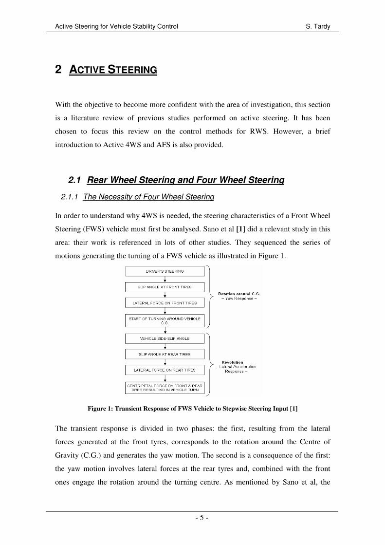
In order to understand why 4WS is needed, the steering characteristics of a Front Wheel
Steering (FWS) vehicle must first be analysed. Sano et al [1] did a relevant study in this
area: their work is referenced in lots of other studies. They sequenced the series of
motions generating the turning of a FWS vehicle as illustrated in Figure 1.
Figure 1: Transient Response of FWS Vehicle to Stepwise Steering Input [1]
The transient response is divided in two phases: the first, resulting from the lateral
forces generated at the front tyres, corresponds to the rotation around the Centre of
Gravity (C.G.) and generates the yaw motion. The second is a consequence of the first:
the yaw motion involves lateral forces at the rear tyres and, combined with the front
ones engage the rotation around the turning centre. As mentioned by Sano et al, the
Active Steering for Vehicle Stability Control S. Tardy
- 6 -
overall vehicle rotation is subject to a delay mainly due to vehicle forward speed and
vehicle inertia.
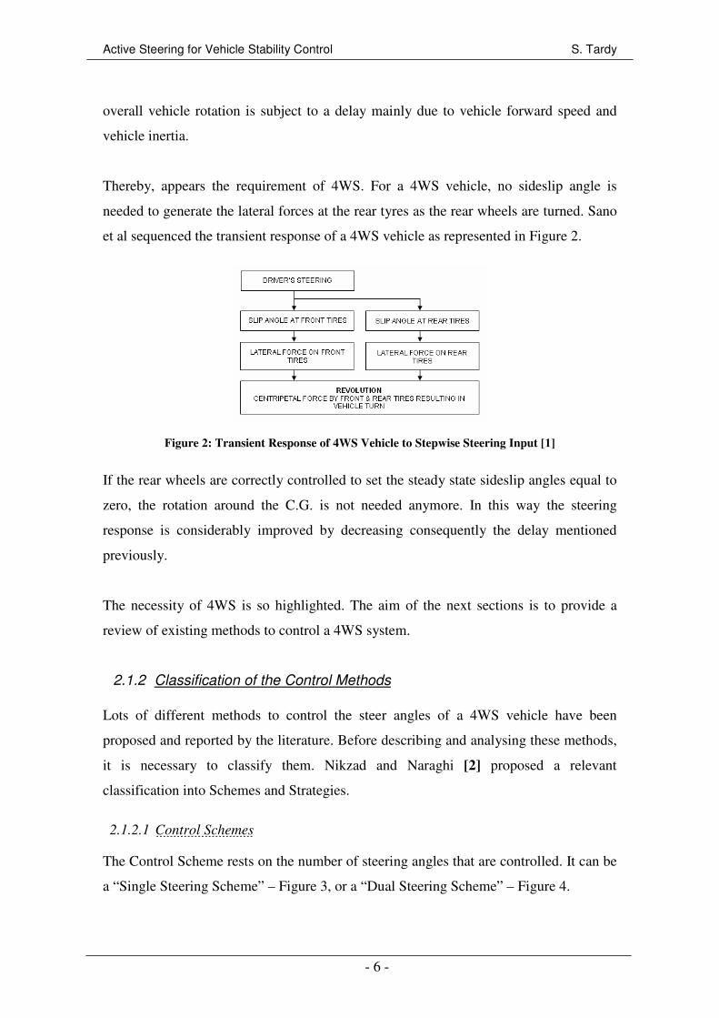
Thereby, appears the requirement of 4WS. For a 4WS vehicle, no sideslip angle is
needed to generate the lateral forces at the rear tyres as the rear wheels are turned. Sano
et al sequenced the transient response of a 4WS vehicle as represented in Figure 2.
Figure 2: Transient Response of 4WS Vehicle to Stepwise Steering Input [1]
If the rear wheels are correctly controlled to set the steady state sideslip angles equal to
zero, the rotation around the C.G. is not needed anymore. In this way the steering
response is considerably improved by decreasing consequently the delay mentioned
previously.
The necessity of 4WS is so highlighted. The aim of the next sections is to provide a
review of existing methods to control a 4WS system.
2.1.2 Classification of the Control Methods
Lots of different methods to control the steer angles of a 4WS vehicle have been
proposed and reported by the literature. Before describing and analysing these methods,
it is necessary to classify them. Nikzad and Naraghi [2] proposed a relevant
classification into Schemes and Strategies.
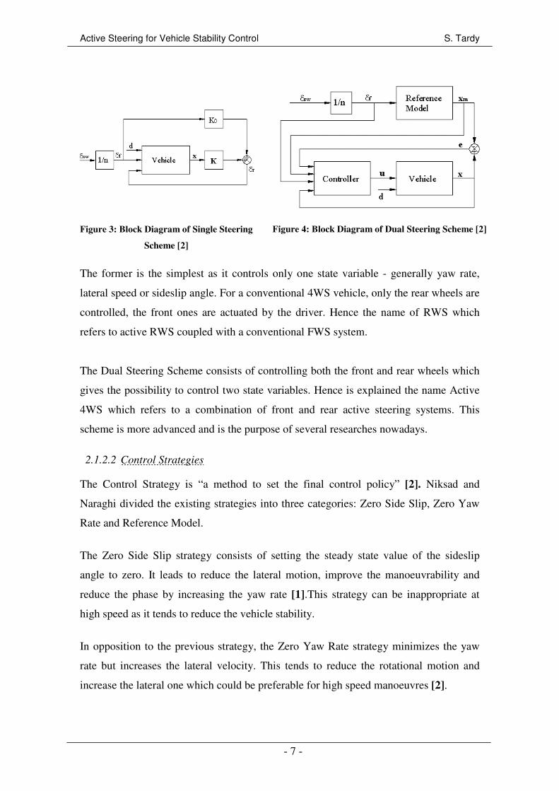
2.1.2.1 Control Schemes
The Control Scheme rests on the number of steering angles that are controlled. It can be
a “Single Steering Scheme” – Figure 3, or a “Dual Steering Scheme” – Figure 4.
Active Steering for Vehicle Stability Control S. Tardy
- 7 -
Figure 3: Block Diagram of Single Steering
Scheme [2]
Figure 4: Block Diagram of Dual Steering Scheme [2]
The former is the simplest as it controls only one state variable - generally yaw rate,
lateral speed or sideslip angle. For a conventional 4WS vehicle, only the rear wheels are
controlled, the front ones are actuated by the driver. Hence the name of RWS which
refers to active RWS coupled with a conventional FWS system.
The Dual Steering Scheme consists of controlling both the front and rear wheels which
gives the possibility to control two state variables. Hence is explained the name Active
4WS which refers to a combination of front and rear active steering systems. This
scheme is more advanced and is the purpose of several researches nowadays.
2.1.2.2 Control Strategies
The Control Strategy is “a method to set the final control policy” [2]. Niksad and
Naraghi divided the existing strategies into three categories: Zero Side Slip, Zero Yaw
Rate and Reference Model.
The Zero Side Slip strategy consists of setting the steady state value of the sideslip
angle to zero. It leads to reduce the lateral motion, improve the manoeuvrability and
reduce the phase by increasing the yaw rate [1].This strategy can be inappropriate at
high speed as it tends to reduce the vehicle stability.
In opposition to the previous strategy, the Zero Yaw Rate strategy minimizes the yaw
rate but increases the lateral velocity. This tends to reduce the rotational motion and
increase the lateral one which could be preferable for high speed manoeuvres [2].
Active Steering for Vehicle Stability Control S. Tardy
- 8 -
The third strategy proposed by Niksad et al – Reference Model – is a combination of the
previous two and considers a reference model to be tracked. Generally, the reference
model is only influenced by the front steer angle and does not consider the controlled
state variables. Niksad and Naraghi showed that a reference model can lead to less
transient vibration with more reliability. Moreover, the use of a reference model with
Dual Steering Scheme gives the best handling response but it is a complex control
device – details in Section 2.2.
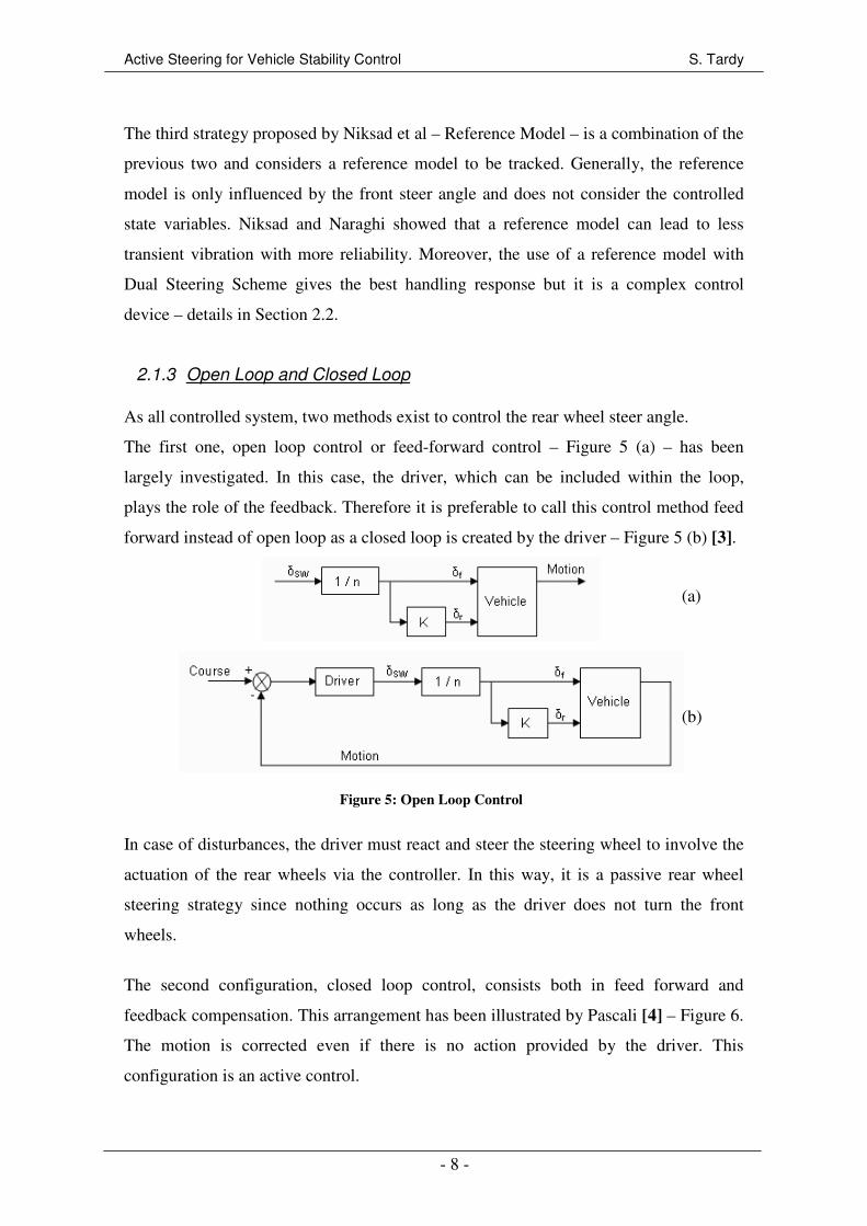
2.1.3 Open Loop and Closed Loop
As all controlled system, two methods exist to control the rear wheel steer angle.
The first one, open loop control or feed-forward control – Figure 5 (a) – has been
largely investigated. In this case, the driver, which can be included within the loop,
plays the role of the feedback. Therefore it is preferable to call this control method feed
forward instead of open loop as a closed loop is created by the driver – Figure 5 (b) [3].
Figure 5: Open Loop Control
In case of disturbances, the driver must react and steer the steering wheel to involve the
actuation of the rear wheels via the controller. In this way, it is a passive rear wheel
steering strategy since nothing occurs as long as the driver does not turn the front
wheels.
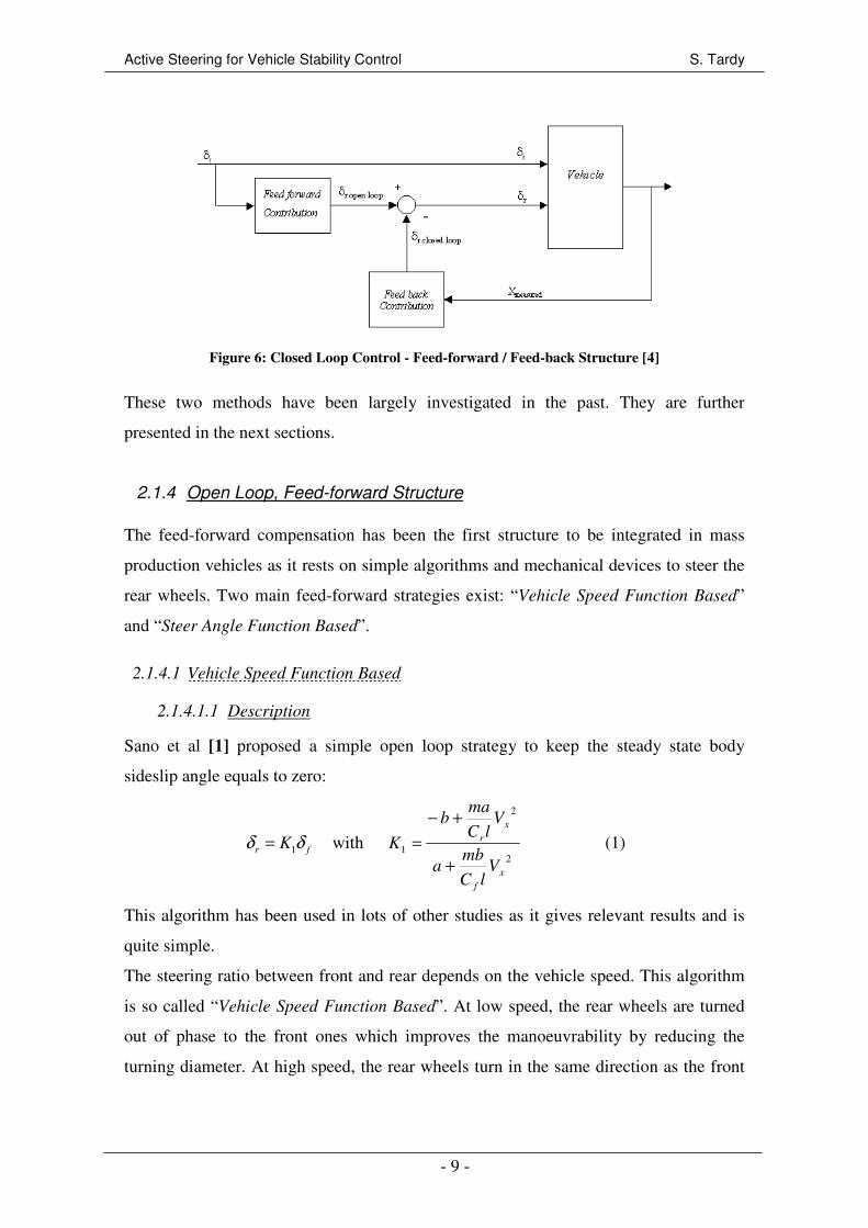
The second configuration, closed loop control, consists both in feed forward and
feedback compensation. This arrangement has been illustrated by Pascali [4] – Figure 6.
The motion is corrected even if there is no action provided by the driver. This
configuration is an active control.
(a)
(b)
Active Steering for Vehicle Stability Control S. Tardy
- 9 -
Figure 6: Closed Loop Control - Feed-forward / Feed-back Structure [4]
These two methods have been largely investigated in the past. They are further
presented in the next sections.
2.1.4 Open Loop, Feed-forward Structure
The feed-forward compensation has been the first structure to be integrated in mass
production vehicles as it rests on simple algorithms and mechanical devices to steer the
rear wheels. Two main feed-forward strategies exist: “Vehicle Speed Function Based”
and “Steer Angle Function Based”.
2.1.4.1 Vehicle Speed Function Based
2.1.4.1.1 Description
Sano et al [1] proposed a simple open loop strategy to keep the steady state body
sideslip angle equals to zero:
1r fKδ δ=
with
2
2
1
x
f
x
r
VlC
mba
VlC
mab
K
+
+−
= (1)
This algorithm has been used in lots of other studies as it gives relevant results and is
quite simple.
The steering ratio between front and rear depends on the vehicle speed. This algorithm
is so called “Vehicle Speed Function Based”. At low speed, the rear wheels are turned
out of phase to the front ones which improves the manoeuvrability by reducing the
turning diameter. At high speed, the rear wheels turn in the same direction as the front
-
Active Steering for Vehicle Stability Control S. Tardy
- 10 -
wheels improving the handling behaviour and the stability. Despite these characteristics,
the implementation complexity is slightly increased by the use of a speed sensor.
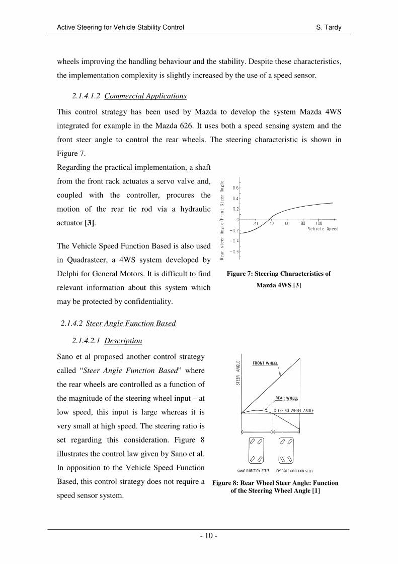
2.1.4.1.2 Commercial Applications
This control strategy has been used by Mazda to develop the system Mazda 4WS
integrated for example in the Mazda 626. It uses both a speed sensing system and the
front steer angle to control the rear wheels. The steering characteristic is shown in
Figure 7.
Regarding the practical implementation, a shaft
from the front rack actuates a servo valve and,
coupled with the controller, procures the
motion of the rear tie rod via a hydraulic
actuator [3].
The Vehicle Speed Function Based is also used
in Quadrasteer, a 4WS system developed by
Delphi for General Motors. It is difficult to find
relevant information about this system which
may be protected by confidentiality.
Figure 7: Steering Characteristics of
Mazda 4WS [3]
2.1.4.2 Steer Angle Function Based
2.1.4.2.1 Description
Sano et al proposed another control strategy
called “Steer Angle Function Based” where
the rear wheels are controlled as a function of
the magnitude of the steering wheel input – at
low speed, this input is large whereas it is
very small at high speed. The steering ratio is
set regarding this consideration. Figure 8
illustrates the control law given by Sano et al.
In opposition to the Vehicle Speed Function
Based, this control strategy does not require a
speed sensor system.
Figure 8: Rear Wheel Steer Angle: Function
of the Steering Wheel Angle [1]
Active Steering for Vehicle Stability Control S. Tardy
- 11 -
2.1.4.2.2 Commercial Application
The Steer Angle Function Based was used in the Honda 4WS system [3]. In 1987, this
system was the first 4WS system integrated in a mass production vehicle: the Honda
Prelude. From a practical aspect, the rear steering system is actuated mechanically via a
shaft form the front steering system and a gearbox to achieved the desired ratio.
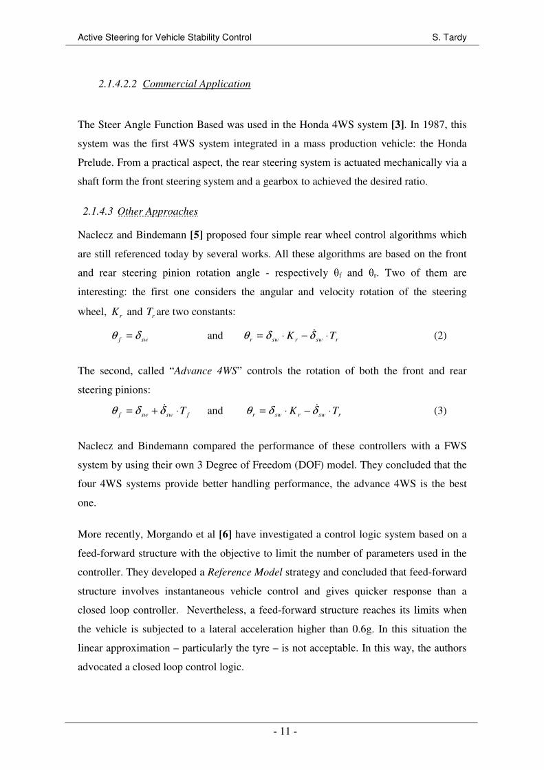
2.1.4.3 Other Approaches
Naclecz and Bindemann [5] proposed four simple rear wheel control algorithms which
are still referenced today by several works. All these algorithms are based on the front
and rear steering pinion rotation angle - respectively θf and θr. Two of them are
interesting: the first one considers the angular and velocity rotation of the steering
wheel, r
K and r
T are two constants:
swf δθ = and rswrswr TK ⋅−⋅= δδθ & (2)
The second, called “Advance 4WS” controls the rotation of both the front and rear
steering pinions:
fswswf T⋅+= δδθ & and rswrswr TK ⋅−⋅= δδθ & (3)
Naclecz and Bindemann compared the performance of these controllers with a FWS
system by using their own 3 Degree of Freedom (DOF) model. They concluded that the
four 4WS systems provide better handling performance, the advance 4WS is the best
one.
More recently, Morgando et al [6] have investigated a control logic system based on a
feed-forward structure with the objective to limit the number of parameters used in the
controller. They developed a Reference Model strategy and concluded that feed-forward
structure involves instantaneous vehicle control and gives quicker response than a
closed loop controller. Nevertheless, a feed-forward structure reaches its limits when
the vehicle is subjected to a lateral acceleration higher than 0.6g. In this situation the
linear approximation – particularly the tyre – is not acceptable. In this way, the authors
advocated a closed loop control logic.
Active Steering for Vehicle Stability Control S. Tardy
- 12 -
2.1.5 Closed Loop Structure
Closed loop control appears as more advanced and more complex than open loop
control. However, it allows the considerable improvement of the system performance
and provides a better rejection of disturbances. Closed loop control refers to active
control: the rear wheels are steered even if the driver does not procure any action.
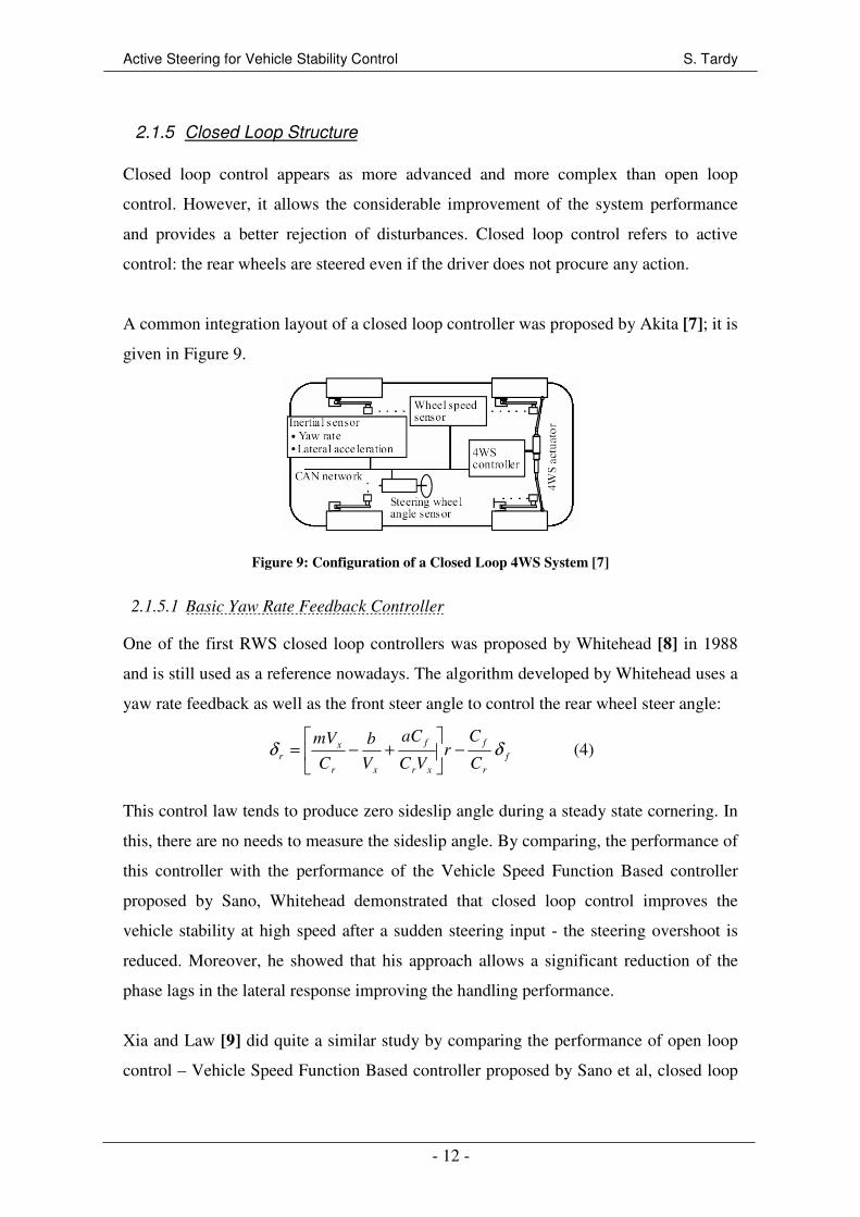
A common integration layout of a closed loop controller was proposed by Akita [7]; it is
given in Figure 9.
Figure 9: Configuration of a Closed Loop 4WS System [7]
2.1.5.1 Basic Yaw Rate Feedback Controller
One of the first RWS closed loop controllers was proposed by Whitehead [8] in 1988
and is still used as a reference nowadays. The algorithm developed by Whitehead uses a
yaw rate feedback as well as the front steer angle to control the rear wheel steer angle:
f
r
f
xr
f
xr
x
rC
Cr
VC
aC
V
b
C
mVδδ −
+−= (4)
This control law tends to produce zero sideslip angle during a steady state cornering. In
this, there are no needs to measure the sideslip angle. By comparing, the performance of
this controller with the performance of the Vehicle Speed Function Based controller
proposed by Sano, Whitehead demonstrated that closed loop control improves the
vehicle stability at high speed after a sudden steering input - the steering overshoot is
reduced. Moreover, he showed that his approach allows a significant reduction of the
phase lags in the lateral response improving the handling performance.
Xia and Law [9] did quite a similar study by comparing the performance of open loop
control – Vehicle Speed Function Based controller proposed by Sano et al, closed loop

Active Steering for Vehicle Stability Control S. Tardy
- 13 -
control – algorithm proposed by Whitehead, and a FWS system. They evaluated “the
collision avoidance performance during combined hard braking and severe steering”
with a non-linear 5-DOF vehicle model. The authors noticed that, because of a strong
oversteering behaviour of the 4WS vehicles, a larger steering input, and so a higher
driver workload is needed for the two 4WS systems to achieve the same yaw rate as the
FWS vehicle. Under 4° steering input, the yaw rate responses are similar for the open
and closed loop systems. However, above 4°, the non-linearity of the tyres highlights
better performances for the closed loop system - higher yaw rate. Xia and Law’s
conclusions were similar to those obtained by Whitehead a couple of years before.
Lee [10] did an interesting work to compare open and closed loop controller by
including the driver in the loop. By achieving computed and “on the road” simulations,
Lee observed that the performance achievable with a 4WS vehicle (both open loop and
closed loop) in high speed change lane change manoeuvre are not significant for an
experienced driver in comparison with a FWS vehicle. In this way, Lee reconsidered the
conclusions got by Xia and Whitehead. However, this must be considered warily as the
Lee’s study relies on a specific experienced driver model.
More recently, researches have been focused on more sophisticated closed loop
controllers using advanced control algorithms. Some of them are presented in the next
section.
2.1.5.2 Reference Model Strategy
Pascali et al [4] investigated the use of the reference model strategy to improve the
vehicle handling and comfort. They developed a target controller with the objective to
reach the best handling performance. The layout of their controller is represented in
Figure 10.
Active Steering for Vehicle Stability Control S. Tardy
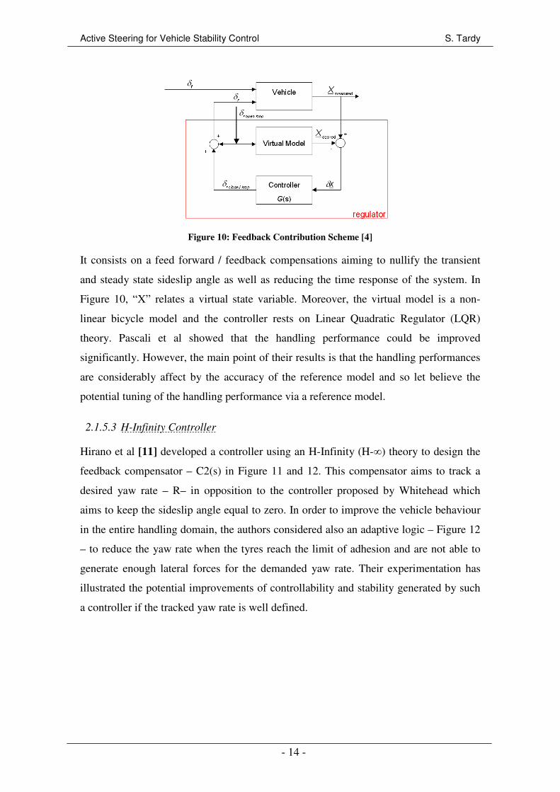
- 14 -
Figure 10: Feedback Contribution Scheme [4]
It consists on a feed forward / feedback compensations aiming to nullify the transient
and steady state sideslip angle as well as reducing the time response of the system. In
Figure 10, “X” relates a virtual state variable. Moreover, the virtual model is a non-
linear bicycle model and the controller rests on Linear Quadratic Regulator (LQR)
theory. Pascali et al showed that the handling performance could be improved
significantly. However, the main point of their results is that the handling performances
are considerably affect by the accuracy of the reference model and so let believe the
potential tuning of the handling performance via a reference model.
2.1.5.3 H-Infinity Controller
Hirano et al [11] developed a controller using an H-Infinity (H-∞) theory to design the
feedback compensator – C2(s) in Figure 11 and 12. This compensator aims to track a
desired yaw rate – R– in opposition to the controller proposed by Whitehead which
aims to keep the sideslip angle equal to zero. In order to improve the vehicle behaviour
in the entire handling domain, the authors considered also an adaptive logic – Figure 12
– to reduce the yaw rate when the tyres reach the limit of adhesion and are not able to
generate enough lateral forces for the demanded yaw rate. Their experimentation has
illustrated the potential improvements of controllability and stability generated by such
a controller if the tracked yaw rate is well defined.
Active Steering for Vehicle Stability Control S. Tardy
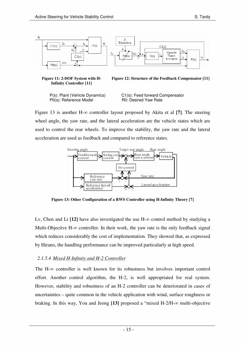
- 15 -
Figure 11: 2-DOF System with H-
Infinity Controller [11]
Figure 12: Structure of the Feedback Compensator [11]
P(s): Plant (Vehicle Dynamics) C1(s): Feed forward Compensator P0(s): Reference Model R0: Desired Yaw Rate
Figure 13 is another H-∞ controller layout proposed by Akita et al [7]. The steering
wheel angle, the yaw rate, and the lateral acceleration are the vehicle states which are
used to control the rear wheels. To improve the stability, the yaw rate and the lateral
acceleration are used as feedback and compared to reference states.
Figure 13: Other Configuration of a RWS Controller using H-Infinity Theory [7]
Lv, Chen and Li [12] have also investigated the use H-∞ control method by studying a
Multi-Objective H-∞ controller. In their work, the yaw rate is the only feedback signal
which reduces considerably the cost of implementation. They showed that, as expressed
by Hirano, the handling performance can be improved particularly at high speed.
2.1.5.4 Mixed H-Infinity and H-2 Controller
The H-∞ controller is well known for its robustness but involves important control
effort. Another control algorithm, the H-2, is well appropriated for real system.
However, stability and robustness of an H-2 controller can be deteriorated in cases of
uncertainties – quite common in the vehicle application with wind, surface roughness or
braking. In this way, You and Jeong [13] proposed a “mixed H-2/H-∞ multi-objective
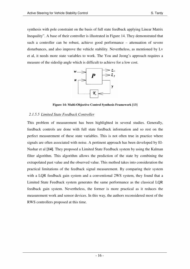
Active Steering for Vehicle Stability Control S. Tardy
- 16 -
synthesis with pole constraint on the basis of full state feedback applying Linear Matrix
Inequality”. A base of their controller is illustrated in Figure 14. They demonstrated that
such a controller can be robust, achieve good performance – attenuation of severe
disturbances, and also improve the vehicle stability. Nevertheless, as mentioned by Lv
et al, it needs more state variables to work. The You and Jeong’s approach requires a
measure of the sideslip angle which is difficult to achieve for a low cost.
Figure 14: Multi-Objective Control Synthesis Framework [13]
2.1.5.5 Limited State Feedback Controller
This problem of measurement has been highlighted in several studies. Generally,
feedback controls are done with full state feedback information and so rest on the
perfect measurement of these state variables. This is not often true in practice where
signals are often associated with noise. A pertinent approach has been developed by El-
Nashar et al [14]. They proposed a Limited State Feedback system by using the Kalman
filter algorithm. This algorithm allows the prediction of the state by combining the
extrapolated past value and the observed value. This method takes into consideration the
practical limitations of the feedback signal measurement. By comparing their system
with a LQR feedback gain system and a conventional 2WS system, they found that a
Limited State Feedback system generates the same performance as the classical LQR
feedback gain system. Nevertheless, the former is more practical as it reduces the
measurement work and sensor devices. In this way, the authors reconsidered most of the
RWS controllers proposed at this time.
Active Steering for Vehicle Stability Control S. Tardy
- 17 -
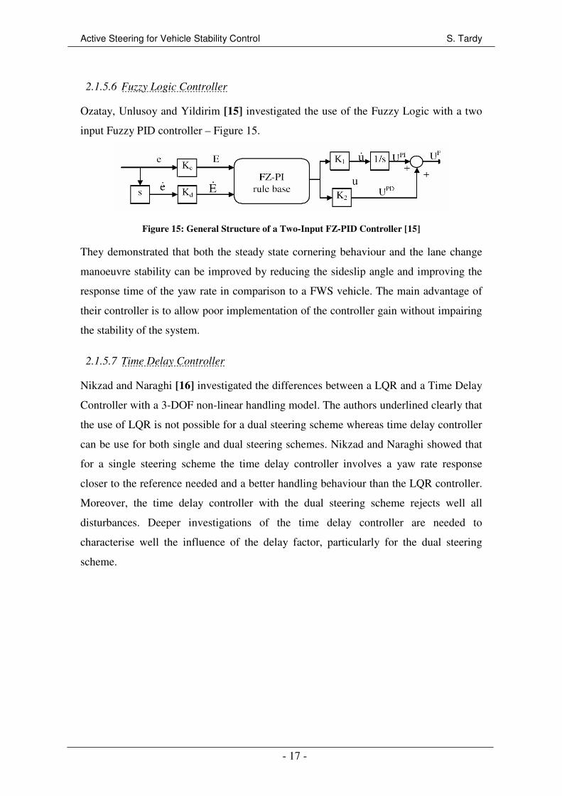
2.1.5.6 Fuzzy Logic Controller
Ozatay, Unlusoy and Yildirim [15] investigated the use of the Fuzzy Logic with a two
input Fuzzy PID controller – Figure 15.
Figure 15: General Structure of a Two-Input FZ-PID Controller [15]
They demonstrated that both the steady state cornering behaviour and the lane change
manoeuvre stability can be improved by reducing the sideslip angle and improving the
response time of the yaw rate in comparison to a FWS vehicle. The main advantage of
their controller is to allow poor implementation of the controller gain without impairing
the stability of the system.
2.1.5.7 Time Delay Controller
Nikzad and Naraghi [16] investigated the differences between a LQR and a Time Delay
Controller with a 3-DOF non-linear handling model. The authors underlined clearly that
the use of LQR is not possible for a dual steering scheme whereas time delay controller
can be use for both single and dual steering schemes. Nikzad and Naraghi showed that
for a single steering scheme the time delay controller involves a yaw rate response
closer to the reference needed and a better handling behaviour than the LQR controller.
Moreover, the time delay controller with the dual steering scheme rejects well all
disturbances. Deeper investigations of the time delay controller are needed to
characterise well the influence of the delay factor, particularly for the dual steering
scheme.
Active Steering for Vehicle Stability Control S. Tardy
- 18 -
2.2 Active Four Wheel Steering – Dual Steering Scheme
First of all, as said before, Active 4WS refers to an active system which controls both
front and rear steer angles. It can be also referred as Dual Steering Scheme.
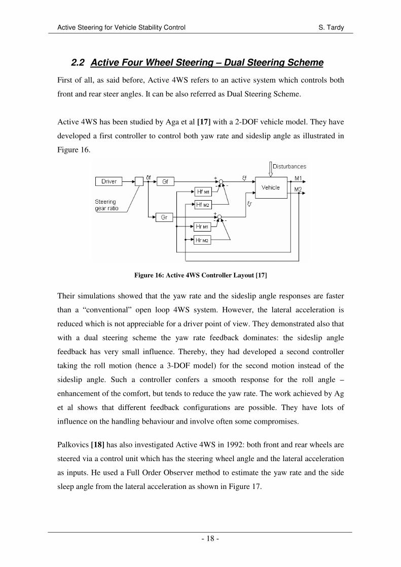
Active 4WS has been studied by Aga et al [17] with a 2-DOF vehicle model. They have
developed a first controller to control both yaw rate and sideslip angle as illustrated in
Figure 16.
Figure 16: Active 4WS Controller Layout [17]
Their simulations showed that the yaw rate and the sideslip angle responses are faster
than a “conventional” open loop 4WS system. However, the lateral acceleration is
reduced which is not appreciable for a driver point of view. They demonstrated also that
with a dual steering scheme the yaw rate feedback dominates: the sideslip angle
feedback has very small influence. Thereby, they had developed a second controller
taking the roll motion (hence a 3-DOF model) for the second motion instead of the
sideslip angle. Such a controller confers a smooth response for the roll angle –
enhancement of the comfort, but tends to reduce the yaw rate. The work achieved by Ag
et al shows that different feedback configurations are possible. They have lots of
influence on the handling behaviour and involve often some compromises.
Palkovics [18] has also investigated Active 4WS in 1992: both front and rear wheels are
steered via a control unit which has the steering wheel angle and the lateral acceleration
as inputs. He used a Full Order Observer method to estimate the yaw rate and the side
sleep angle from the lateral acceleration as shown in Figure 17.

Active Steering for Vehicle Stability Control S. Tardy
- 19 -
Figure 17: Full Order Observer Layout [18]
In this way, he used the simplest variable to measure – lateral acceleration – and avoids
measuring the sideslip angle. Moreover, the Palkovics’ work was based on a reference
model strategy where the real vehicle had to follow a virtual reference model. He also
included the driver in the model as illustrated in Figure 18 where the complete driver-
vehicle system is represented.
Figure 18: Active 4WS Observer Layout, Driver-Vehicle System [17]
The main conclusion obtained by Palkovics is that, with a full order observer, the design
parameters of the controller are crucial regarding the system performance: a
configuration very performing for a given vehicle can become unstable if a simple
parameter as the tyre stiffness is slightly changed. In regards to the weakness of this
controller, Palkovics advices the use of robust controller or adaptive controller for
Active 4WS.
2.3 Active Front Steering
2.3.1 Description
Active Front Steering – commonly called AFS – consists of superposing a controlled
angle to the steering wheel angle as represented in Figure 19. Indeed, from the steering
wheel driver’s command δsw is added an active component δfactive via a planetary gear
set. This additional degree of freedom enables a continuous and driving dependent

Active Steering for Vehicle Stability Control S. Tardy
- 20 -
adaptation of the steering characteristics. Features like steering comfort, driver work
load and steering dynamics are optimized; stabilizing steering intervention can also be
performed.
The permanent mechanical connection between the steering wheel and the wheels
remains. Therefore, it is important to notice that AFS must not be considered as a steer-
by-wire device – not permitted by the law at this day.
Figure 19: Principle of the Angle Superposition [20] - [21]
The first AFS system has been developed by ZF Lenksysteme and BMW [19] and
introduced in the new BMW 5-series in 2003. Klier et al. from ZF Lenksysteme [20] -
[21] presented the main features and characteristics of their system. These papers are
very interesting and formative as this system is the first to be integrated in a
commercialized vehicle. The practical implementation is not presented here, however it
could be refer to [20] - [21] for further details.
2.3.2 Control Strategies
Several studies have been done on AFS [22 to 25]. Most of them used a reference
model strategy – this concept will be further presented in Section 2.1.5.2.
Oraby et al [22] proposed the controller which consists on a feed forward/feedback
controller using the LQR theory to obtain the optimal design. Other investigations have
been carried out with the same controller structure, using H-∞ control theory [23], or the
sliding mode technique [24] to enhance the robustness.
All the studies showed that AFS is very interesting at low and moderate lateral
acceleration by improving considerably the handling characteristics.

Active Steering for Vehicle Stability Control S. Tardy
- 21 -
2.4 Closing Comments
To conclude this review, several important observations and conclusions have to be
highlighted. First, two main categories of controller layouts have been investigated in
the literature: the feed forward compensation which exploits the driver’s steering wheel
angle as system input, and the feedback compensation which uses state variables of the
vehicle as input. The former has already been integrated in passenger cars, but it cannot
be considered as an active device. A combination of the two compensations – feed
forward/feedback – appears as the best configuration for RWS controllers. This method
of active control can provide high performance: stability, responsiveness, robustness
and reliability.
The literature does not allow the identification of the best configuration for these feed
forward/feedback structures. Indeed, a relevant comparison of the different controllers
has not been studied. Provide its own comparison and conclusions is also delicate as all
the investigated controllers rest on different assumptions, dynamic models and are
always the result of compromises. However, the use of simple compensator –
Proportional Integral – may give very relevant results in spite of the utilisation of
advance theories, as LQR or H-∞ theories would improve the controller robustness.
Moreover, integrated a reference model into the loop is also interesting and necessary.
A desired steering response can therefore be achieved and tune the handling
performance becomes possible.
Active Steering for Vehicle Stability Control S. Tardy
- 22 -
3 SIMULATION ENVIRONMENT
The simulation environment is a key aspect of this study. The aim of this section is to
provide a brief introduction to this environment. Firstly, IPG Carmaker is introduced,
and then its interaction with Matlab/Simulink is discussed.
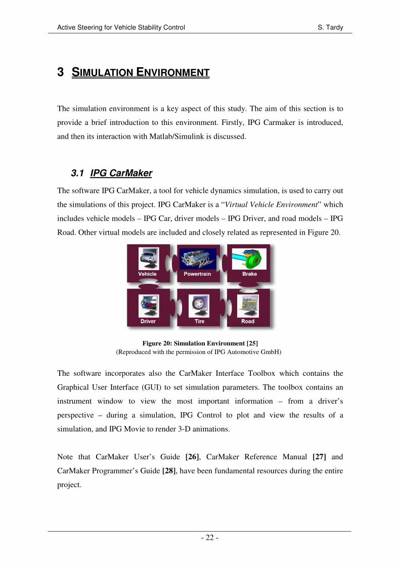
3.1 IPG CarMaker
The software IPG CarMaker, a tool for vehicle dynamics simulation, is used to carry out
the simulations of this project. IPG CarMaker is a “Virtual Vehicle Environment” which
includes vehicle models – IPG Car, driver models – IPG Driver, and road models – IPG
Road. Other virtual models are included and closely related as represented in Figure 20.
Figure 20: Simulation Environment [25]
The software incorporates also the CarMaker Interface Toolbox which contains the
Graphical User Interface (GUI) to set simulation parameters. The toolbox contains an
instrument window to view the most important information – from a driver’s
perspective – during a simulation, IPG Control to plot and view the results of a
simulation, and IPG Movie to render 3-D animations.
Note that CarMaker User’s Guide [26], CarMaker Reference Manual [27] and
CarMaker Programmer’s Guide [28], have been fundamental resources during the entire
project.
(Reproduced with the permission of IPG Automotive GmbH)

Active Steering for Vehicle Stability Control S. Tardy
- 23 -
3.2 IPG CarMaker for Simulink
IPG CarMaker provides also a connection with Matlab/Simulink – IPG CarMaker for
Simulink, where the CarMaker features are added to Simulink via S-Function
implementations. This interface CarMaker/Simulink is represented in Figure 21.
Figure 21: Interface IPG CarMaker – Simulink [25]
The CarMaker environment executes an advanced Simulink model of the vehicle – see
Section 5.2 – and the driver. In this configuration, CarMaker accounts for the conductor
of the simulation process via the “Sync_In” / “Sync_Out” variables in Simulink.
CarMaker is also where are defined vehicle parameters, test scenarios, driver
characteristics, and all the other data needed for a simulation.
To ensure the interaction between Simulink and CarMaker, several functions are added
in the Simulink library as “Read CM Dict” which allows Simulink to access and import
CarMaker variables in Simulink, or “Define CM Dict” and “Write CM Dict” to define
and write Simulink variables in the CarMaker dictionary.
In spite of CarMaker is a very performing simulation tool, some constraints have to be
highlighted since they have influences on the study. Indeed, first of all, most of the
CarMaker blocks in Simulink are locked S-functions and cannot be accessed by the user
(Reproduced with the permission of IPG Automotive GmbH)
Active Steering for Vehicle Stability Control S. Tardy
- 24 -
which reduces the possibilities to implement new systems without creating a new block.
Moreover, the vehicle model in Simulink cannot be linearized and so frequency or root
locus analyses are not conceivable. Furthermore, the tool IPG Control, which is used to
plot simulations results, does not allow the displaying of results from two different
simulations in a same window. Therefore, all the results have to be imported – cmread
function, and processed in Matlab to provide relevant comparisons. Note that as
CarMaker is a real simulation environment, the vehicle is necessarily immobile at the
beginning of a simulation: a period of acceleration is always needed. This uninteresting
part of the simulation has also to be removed during the data processing in Matlab.

Active Steering for Vehicle Stability Control S. Tardy
- 25 -
4 REQUIREMENT CAPTURE
The objective of this section is to draw up specifications for the systems under study -
AFS and RWS. The use of a requirement capture aims to consider most of the important
aspects and to highlight crucial questions for the design. The main principles of a
Requirement Capture for automotive systems have been developed by Gebhard [29].
The requirement capture undertook here is a functional one since the requirement is
“directly connected with the behaviour of the intended system” [29]. A functional
requirement capture defines the problem and gives answer to “Why this system?” and
“What has it to do?” The capture is carried out by writing a Use Case as proposed by
Alistair Cockburn [30]. The task is so divided in three main stages:
- Definition of the level of investigation, the primary actors and the scope.
- Writing of the Use Case.
- Getting useful conclusions regarding the objectives of the system.
4.1 Level, Primary Actors and Scope
Before writing the Use Case, the level of investigation, the primary actors and the scope
must be clearly defined. The investigation is done at a higher level as the studies is
“model based”. The primary actor “who initiates an interaction with the system to
accomplish some goals” [30], is obviously the driver. The scope, which defines the
boundaries of the system, allows the identification of “what is really the system under
discussion?” It is obtained by defining the elements surrounding the system. Figure 22
illustrates the scope definition and the interacting elements. Note that, in order to
achieve a performing Use Case, all considerations have to be included even if they will
not be used during the design process.

Active Steering for Vehicle Stability Control S. Tardy
- 26 -
Figure 22: Scope for the Use Case
In Figure 22, the environment includes the road, external disturbances as the wind, the
temperature, etc. This figure shows that the system under consideration is the steering
system and the related controller which interact with several external elements and the
driver.
4.2 Use Case
The scope being clearly defined, the requirement capture leads to write a Use Case as
illustrated in Table 1. Lots of ways are conceivable to write a Use Case but it has been
chosen to present it in a Table as suggested by Alistair Cockburn. This Use Case is
applicable for both AFS and RWS since the two systems must responds to the same
requirement for a relevant comparison.
Note that a complete Use Case would also consider alternative and error flow. However,
regarding the aim of this study, these flows are not essential. Therefore, only the main
flow has been considered.
Longitudinal speed sensor
Steering wheel angle sensor
Environment
Electro-mechanical actuator
Yaw rate sensor
SCOPE
SYSTEM
Driver
PRIMARY ACTOR
Lateral acceleration sensor

Active Steering for Vehicle Stability Control S. Tardy
- 27 -
Table 1: Use Case
USE CASE Improve the vehicle stability, expand the handling region
Context of Use Reduction or loss of the stability at high speed
Scope Active Steering Control System
Level Summary
System Steering system
Primary Actor Driver
Stakeholder & Interests Stakeholder Interests
Driver
Follow a given direction Feel responsive, accurate Less under/oversteering Low steering work
Car manufacturer Customer satisfaction
Preconditions None
Minimal Guarantees Driver always kept informed Rely to the driver, always able to turn the vehicle, minimal turning characteristics
Success Guarantees
Vehicle follows the desired path Vehicle more stable Vehicle less under/oversteering No delay Good feedback feeling
Trigger Predefined state variables are verified
Description Step Action
1 Driver turns the steering wheel
2 System validates driver request
3 System verifies all the data needed for the reference model (forward speed, steer input) if existing
4 System measures and verifies a predefined state variable
5 System compares the state variable with the one given by the reference model or another source
6 System generates corrective action
7 Vehicle follows the required path
Extensions Step Action
3a Sensor, controller failure
3a1 Use a backup strategy
6a Saturation of the actuator
6a1 Provide the maximum possible correction
7a Saturation of the tyres (cannot generate the desired lateral forces)
Data Variations /
Active Steering for Vehicle Stability Control S. Tardy
- 28 -
4.3 Objectives for the Systems
The Use Case presented above has allowed the consideration of several aspects which
should have not been regards with a simple approach. It constitutes a solid guide to
define the objectives and goals for the two systems.
First of all, it is important to remind that, as inquired by Jaguar Land Rover, the system
objectives have to be defined for applications in the high speed range – low speed
manoeuvrability is not considered in this study. As AFS and RWS have to be compared,
they have to respond to the same objectives. Therefore, in the following discussion the
two systems will be grouped into a single name: active steering.
An active steering system may have two distinct objectives:
- Improve the vehicle stability during transient response – better damped, lower
settling time – and keep the steady state behaviour as closer as possible to the
passive vehicle to not influence driver feeling and enjoyment.
- Improve the vehicle handling and stability by achieving a desired steering
response – e.g. neutral steering or less understeering.
Whatever the objective, several goals in a lower level remain similar and they are:
- Reduce the phase lag in the lateral acceleration and yaw rate response. Indeed,
when the vehicle forward speed increases, delays in the lateral acceleration and
the yaw rate increase consequently. This implies a driver work to advance the
phase lead in the steering control. This work load has to be reduced.
- Reduce the vehicle body sideslip angle to fix it as closer as possible to zero.
However, as mentioned in Section 2.1.1, this angle must not be zero for a FWS
steering vehicle.
- Provide better response near the limit of adhesion. The increasing of lateral
acceleration during cornering involves a raise of the lateral forces in the tyre.
This force gets saturated resulting in the decreasing in the tyre stiffness. The
forces in the tyre have to be managed better.
- Reduce the driver work load and so enhance his comfort.
Active Steering for Vehicle Stability Control S. Tardy
- 29 -
4.4 Test Scenarios
The enumeration of these diverse objectives shows that active steering systems aim to
improve the vehicle handling and stability of the vehicle comparing to the passive
vehicle. In this way, a list of test scenarios is defined in order to carry out numerous
simulations to evaluate and compare the systems performance. They have to show the
goals and objectives being achieved by representing real situation as closer as possible.
These scenarios, which are listed below, aspire to represent frequent situations met by
drivers in the real world.
- Test 1: Step steer input without driver control
- Test 2: Step steer input with driver control
- Test 3: Accelerating and turning
- Test 4: Braking and turning
- Test 5: Split-µ braking
- Test 6: ISO double lane change
- Test 7: High speed double lane change
- Test 8: Side wind disturbances without driver control
- Test 9: Side wind disturbances with driver control
All the tests have been implemented in IPG CarMaker. A data sheet of each test is
enclosed in Appendix C; they are also further presented in Section 6.5.
4.5 Closing Comments
This preliminary part of the study is very important. The Use Case has allowed a clear
definition of the scope and the various interactions with the surrounding elements.
Several points have also been highlighted during the preparation of the Use Case which
has led to a complete and relevant definition of the objectives for the active steering
systems.
Active Steering for Vehicle Stability Control S. Tardy
- 30 -
5 VEHICLE MODEL AND VALIDATION
In this chapter, the 3-DOF handling model is introduced. Some typical results are then
displayed to verify the model. Finally, the IPG CarMaker vehicle model is presented
and compared with the 3-DOF model.
5.1 Three Degree of Freedom Handling Model
5.1.1 Presentation
A 3-DOF handling model was developed in Simulink to facilitate some part of the
investigation and to ensure an understanding of the vehicle dynamics background. The
implementation of such a model has allowed a crossed verification with the vehicle
model in CarMaker.
The main features of this model are:
- 3-DOF: longitudinal, yaw and roll motions
- Non-linear tyre model
- Lateral weight transfer
A more detailed description and the derivation of the model can be found in Appendix
B, vehicle parameters are given in Appendix A.
5.1.2 Model Verification
Since the lateral vehicle performance varies consequently with the forward speed and
the linear and non-linear regions can influence significantly the handling behaviour, it is
important to understand and characterize the vehicle response before the design of the
AFS and RWS controllers. This analysis is carried out with the 3-DOF model by using
Matlab/Simulink.
5.1.2.1 Tyre Characteristics
An illustration of saturation phenomena of tyres is given in Figure 23. It can be seen
that as expected for small tyre slip angle, the relation between slip angle and lateral
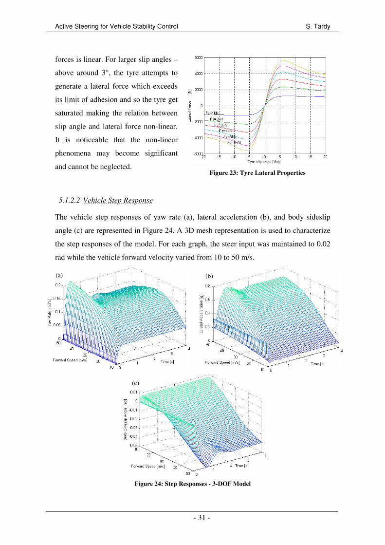
Active Steering for Vehicle Stability Control S. Tardy
- 31 -
forces is linear. For larger slip angles –
above around 3°, the tyre attempts to
generate a lateral force which exceeds
its limit of adhesion and so the tyre get
saturated making the relation between
slip angle and lateral force non-linear.
It is noticeable that the non-linear
phenomena may become significant
and cannot be neglected.
Figure 23: Tyre Lateral Properties
5.1.2.2 Vehicle Step Response
The vehicle step responses of yaw rate (a), lateral acceleration (b), and body sideslip
angle (c) are represented in Figure 24. A 3D mesh representation is used to characterize
the step responses of the model. For each graph, the steer input was maintained to 0.02
rad while the vehicle forward velocity varied from 10 to 50 m/s.
Figure 24: Step Responses - 3-DOF Model
(a) (b)
(c)
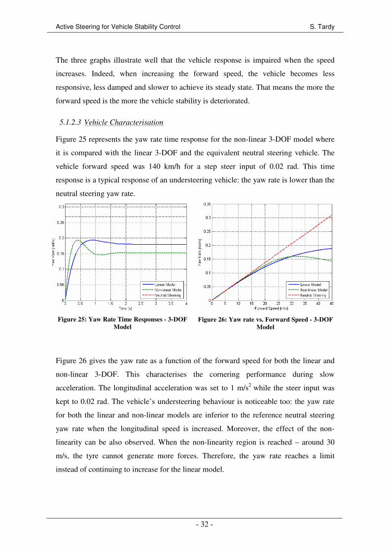
Active Steering for Vehicle Stability Control S. Tardy
- 32 -
The three graphs illustrate well that the vehicle response is impaired when the speed
increases. Indeed, when increasing the forward speed, the vehicle becomes less
responsive, less damped and slower to achieve its steady state. That means the more the
forward speed is the more the vehicle stability is deteriorated.
5.1.2.3 Vehicle Characterisation
Figure 25 represents the yaw rate time response for the non-linear 3-DOF model where
it is compared with the linear 3-DOF and the equivalent neutral steering vehicle. The
vehicle forward speed was 140 km/h for a step steer input of 0.02 rad. This time
response is a typical response of an understeering vehicle: the yaw rate is lower than the
neutral steering yaw rate.
Figure 25: Yaw Rate Time Responses - 3-DOF
Model
Figure 26: Yaw rate vs. Forward Speed - 3-DOF
Model
Figure 26 gives the yaw rate as a function of the forward speed for both the linear and
non-linear 3-DOF. This characterises the cornering performance during slow
acceleration. The longitudinal acceleration was set to 1 m/s2
while the steer input was
kept to 0.02 rad. The vehicle’s understeering behaviour is noticeable too: the yaw rate
for both the linear and non-linear models are inferior to the reference neutral steering
yaw rate when the longitudinal speed is increased. Moreover, the effect of the non-
linearity can be also observed. When the non-linearity region is reached – around 30
m/s, the tyre cannot generate more forces. Therefore, the yaw rate reaches a limit
instead of continuing to increase for the linear model.
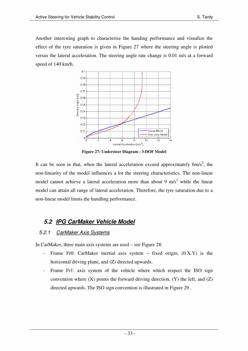
Active Steering for Vehicle Stability Control S. Tardy
- 33 -
Another interesting graph to characterise the handing performance and visualize the
effect of the tyre saturation is given in Figure 27 where the steering angle is plotted
versus the lateral acceleration. The steering angle rate change is 0.01 m/s at a forward
speed of 140 km/h.
Figure 27: Understeer Diagram - 3-DOF Model
It can be seen in that, when the lateral acceleration exceed approximately 6m/s2, the
non-linearity of the model influences a lot the steering characteristics. The non-linear
model cannot achieve a lateral acceleration more than about 9 m/s2 while the linear
model can attain all range of lateral acceleration. Therefore, the tyre saturation due to a
non-linear model limits the handling performance.
5.2 IPG CarMaker Vehicle Model
5.2.1 CarMaker Axis Systems
In CarMaker, three main axis systems are used – see Figure 28:
- Frame Fr0: CarMaker inertial axis system – fixed origin, (0.X.Y) is the
horizontal driving plane, and (Z) directed upwards.
- Frame Fr1: axis system of the vehicle where which respect the ISO sign
convention where (X) points the forward driving direction, (Y) the left, and (Z)
directed upwards. The ISO sign convention is illustrated in Figure 29 .
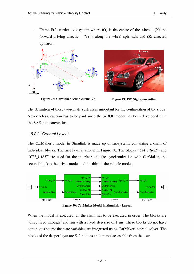
Active Steering for Vehicle Stability Control S. Tardy
- 34 -
- Frame Fr2: carrier axis system where (O) is the centre of the wheels, (X) the
forward driving direction, (Y) is along the wheel spin axis and (Z) directed
upwards.
Figure 28: CarMaker Axis Systems [28]
Figure 29: ISO Sign Convention
The definition of these coordinate systems is important for the continuation of the study.
Nevertheless, caution has to be paid since the 3-DOF model has been developed with
the SAE sign convention.
5.2.2 General Layout
The CarMaker’s model in Simulink is made up of subsystems containing a chain of
individual blocks. The first layer is shown in Figure 30. The blocks “CM_FIRST” and
“CM_LAST” are used for the interface and the synchronization with CarMaker, the
second block is the driver model and the third is the vehicle model.
Figure 30: CarMaker Model in Simulink - Layout
When the model is executed, all the chain has to be executed in order. The blocks are
“direct feed through” and run with a fixed step size of 1 ms. These blocks do not have
continuous states: the state variables are integrated using CarMaker internal solver. The
blocks of the deeper layer are S-functions and are not accessible from the user.

Active Steering for Vehicle Stability Control S. Tardy
- 35 -
Changes in the Simulink model are done by overriding signals and disabling unneeded
internal CarMaker functionalities; replacement, removal or reorder of CarMaker blocks
is not possible.
The entire Simulink model must be understood to be confident with the simulation
environment. However, the main interest here is the “Vehicle” block since AFS and
RWS subsystems will be set in this block. The “Vehicle” block is divided in three
subsystems as represented in Figure 31. The most important for this study is the
“CarAndTrailer” subsystem.
Figure 31: CarMaker Vehicle Model
The “CarAndTrailer” block is formed of five subsystems as shown in Figure 32. The
first three blocks are the most important for the implementation of AFS and RWS. Note
that the “Kinetics” block, which has the forces acting on the vehicle as inputs,
calculates the vehicle motion.
Figure 32: IPG CarMaker Car And Trailer Subsystem

Active Steering for Vehicle Stability Control S. Tardy
- 36 -
5.2.3 Steering Subsystem
The “Steering” system interacts with the “DrivMan” which simulates the human
interactions with the vehicles. It obviously also interrelates with the vehicle suspension
module as represented in Figure 33.
Figure 33: Interface of the Steering System [27]
The system used for the project is a “Steer by Angle” model where the steering wheel
angle is transformed to translational quantities - Figure 34. This basic model simulates a
rack steering system where all the elements are considered stiff. The steering ratio is not
constant, only the average ratio is accessible for the user. Position, velocity and
acceleration are considered in the model.
Figure 34: Steering System [27]
5.2.4 Kinematics Subsystem
The “Kinematics” subsystem is a part of the suspension model. It describes the
movements of the wheels due to the steer action and compression. It includes also the
compliance. Two sources of movement closely linked can be distinguished: the steering
kinematics and the suspension kinematics. The one of interest for the purpose of the
study is mainly the former. In CarMaker, each wheel position and orientation – 3
translations and 3 rotations – are defined in the coordinate systems “Frame Fr2”.

Active Steering for Vehicle Stability Control S. Tardy
- 37 -
5.2.5 Forces Subsystem
5.2.5.1 Presentation
As shown in Figure 35, the “Forces”
subsystem is compounded of three systems:
- “Vehicle Forces”: derives all the
forces acting on the vehicle as
aerodynamic forces or loads.
- “Tires”: derives the forces at each
tyre, the aligning torque and the slip
angle. This block is further
presented in Section 5.2.5.2.
- “External Suspension Forces”:
derives the external forces acting on
the suspension system – springs,
dampers, stabilizer components.
Figure 35: IPG CarMaker Forces Subsystem
5.2.5.2 Tyre Model
The overall structure of the CarMaker tyre model is represented in Figure 36.
Figure 36: Structure of the Tyre Model [27]
Besides the inputs and outputs listed in the
Figure, they are:
- : velocity vector in the tyre-road
contact point
- : velocity of the tyre belt in the tyre-
road contact point
- : tyre forces in the tyre-road contact
point
- : torques in the tyre-road contact point.
The tyre model is so formulated for the tyre-road contact point and aims to calculate the
tyre forces and torques as a function of lateral and longitudinal slip angles, normal
forces in the tyre contact point, camber angle and tyre/road friction coefficient. The
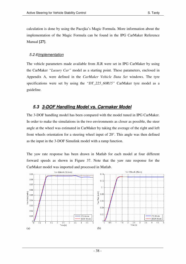
Active Steering for Vehicle Stability Control S. Tardy
- 38 -
calculation is done by using the Pacejka’s Magic Formula. More information about the
implementation of the Magic Formula can be found in the IPG CarMaker Reference
Manual [27].
5.2.6 Implementation
The vehicle parameters made available from JLR were set in IPG CarMaker by using
the CarMaker “Luxury Car” model as a starting point. These parameters, enclosed in
Appendix A, were defined in the CarMaker Vehicle Data Set windows. The tyre
specifications were set by using the “DT_225_60R15” CarMaker tyre model as a
guideline.
5.3 3-DOF Handling Model vs. Carmaker Model
The 3-DOF handling model has been compared with the model tuned in IPG CarMaker.
In order to make the simulations in the two environments as closer as possible, the steer
angle at the wheel was estimated in CarMaker by taking the average of the right and left
front wheels orientation for a steering wheel input of 20°. This angle was then defined
as the input in the 3-DOF Simulink model with a ramp function.
The yaw rate response has been drawn in Matlab for each model at four different
forward speeds as shown in Figure 37. Note that the yaw rate response for the
CarMaker model was imported and processed in Matlab.
(a)
(b)
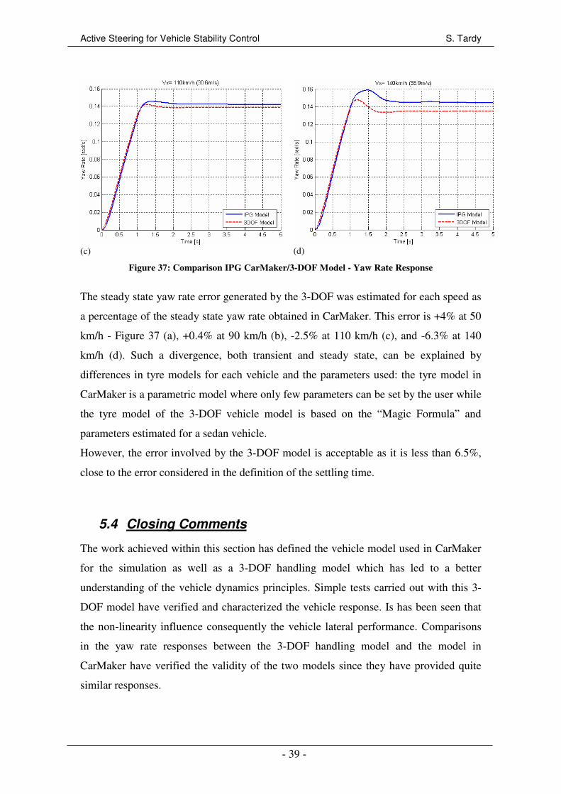
Active Steering for Vehicle Stability Control S. Tardy
- 39 -
(c)
(d)
Figure 37: Comparison IPG CarMaker/3-DOF Model - Yaw Rate Response
The steady state yaw rate error generated by the 3-DOF was estimated for each speed as
a percentage of the steady state yaw rate obtained in CarMaker. This error is +4% at 50
km/h - Figure 37 (a), +0.4% at 90 km/h (b), -2.5% at 110 km/h (c), and -6.3% at 140
km/h (d). Such a divergence, both transient and steady state, can be explained by
differences in tyre models for each vehicle and the parameters used: the tyre model in
CarMaker is a parametric model where only few parameters can be set by the user while
the tyre model of the 3-DOF vehicle model is based on the “Magic Formula” and
parameters estimated for a sedan vehicle.
However, the error involved by the 3-DOF model is acceptable as it is less than 6.5%,
close to the error considered in the definition of the settling time.
5.4 Closing Comments
The work achieved within this section has defined the vehicle model used in CarMaker
for the simulation as well as a 3-DOF handling model which has led to a better
understanding of the vehicle dynamics principles. Simple tests carried out with this 3-
DOF model have verified and characterized the vehicle response. Is has been seen that
the non-linearity influence consequently the vehicle lateral performance. Comparisons
in the yaw rate responses between the 3-DOF handling model and the model in
CarMaker have verified the validity of the two models since they have provided quite
similar responses.
Active Steering for Vehicle Stability Control S. Tardy
- 40 -
6 YAW RATE CONTROL FOR STABILITY IMPROVEMENTS
The literature review presented in Chapter 2 has shown that yaw rate is the state
variable which is the most often controlled in active steering systems whatever the
controller structure – either feed forward or feedback. Moreover, a reference model to
be tracked has been mentioned as necessary. Therefore, the controller developed in this
chapter is a yaw rate feedback controller coupled with a reference model. The controller
design and its implementation are presented. Then, the influence of the actuator and its
bandwidth are discussed. Finally, the performances of the controller are analysed for
both AFS and RWS.
6.1 Design Structure
The yaw rate feedback controller developed here aims to fulfil the first objective
discussed in Section 4.3: improve the vehicle stability during the transient response. The
steady state behaviour has to be kept as closer as possible to the passive vehicle in order
to not influence the overall vehicle response and so maintain the driver feeling and
enjoyment. The use of a reference model involves the combination of the feed forward
and feedback paths – see Section 2.1.3 – in a simple layout. Thus, the advantages of
feed forward and feedback are chunk: achievement of a desired dynamics characteristics
and rejection of external disturbances.
6.1.1 Rear Wheel Steering
The RWS yaw moment control system illustrated in Figure 38 is divided in two parts: a
reference model – presented in Section 6.1.3, and a yaw rate feedback controller. The
later compares the vehicle’s actual yaw rate r with the reference yaw rate r_ref. Then by
applying a proportional and integral control – P+I controller – to the difference in these
rates, the set point U for the active steering actuator is determined. The active steer
angle Delta_r for the rear wheels comes from the active steering actuator – see Section
6.4 – which executes the RWS controller command.
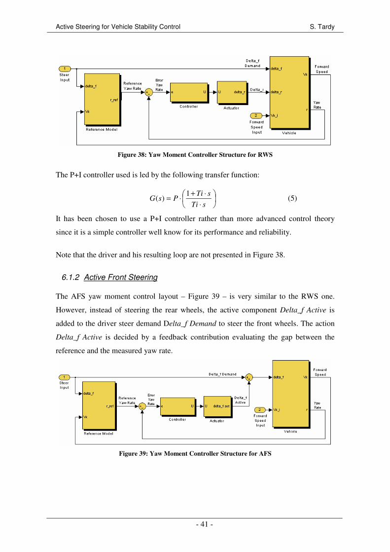
Active Steering for Vehicle Stability Control S. Tardy
- 41 -
Figure 38: Yaw Moment Controller Structure for RWS
The P+I controller used is led by the following transfer function:
⋅
⋅+⋅=
sTi
sTiPsG
1)( (5)
It has been chosen to use a P+I controller rather than more advanced control theory
since it is a simple controller well know for its performance and reliability.
Note that the driver and his resulting loop are not presented in Figure 38.
6.1.2 Active Front Steering
The AFS yaw moment control layout – Figure 39 – is very similar to the RWS one.
However, instead of steering the rear wheels, the active component Delta_f Active is
added to the driver steer demand Delta_f Demand to steer the front wheels. The action
Delta_f Active is decided by a feedback contribution evaluating the gap between the
reference and the measured yaw rate.
Figure 39: Yaw Moment Controller Structure for AFS

Active Steering for Vehicle Stability Control S. Tardy
- 42 -
6.1.3 Reference Yaw Rate
The discussion here is applied to AFS, but it would have been similar for RWS. The
yaw rate target definition is an important part of the controller design. Different
approaches have been investigated. In a first time, a 2-DOF linear bicycle model of the
passive vehicle has been considered to generate the reference yaw rate. However at
moderate speed, this 2-DOF model provides a lower settling time than the passive
vehicle if the linearized cornering stiffness is not precisely estimated. Therefore, in such
a situation, the performance of the active vehicle would have been impaired. On the
other hand, when the vehicle is in the non-linear region at high speed, the 2-DOF
reference model gives a better transient response – both settling time and overshoot –
that the passive vehicle. However, the steady state yaw rate given by the reference
model is much higher than the one generated by the passive vehicle. Thus, the second
objective of the controller – keep the steady state yaw rate of the active vehicle close to
the passive vehicle – would have never been achieved. Besides, in situation of strong
non-linearity, the reference yaw rate is too ambitious and involves the “spin out” of the
vehicle. Indeed, the active system “asks” for higher tyre forces to increase the yaw rate
but the tyres already saturated cannot generate lateral forces anymore.
Furthermore, with such considerations, a neutral steering reference model has been
dismissed as it would have involved higher steady state yaw rate than the 2-DOF model
and so a premature loss of vehicle control.
These two attempts show that the matching of the steady state yaw rate of the passive
vehicle in the non-linear region is a demanding constraint and difficult to achieve since
all the simple models do not account the non-linearity. Considering that the active
systems have to be analysed at high speed and so often close to the non-linear region,
error is the steady state yaw rate cannot be accepted. Therefore, it has finally been
chosen to use a lookup table to match correctly the steady state yaw rate of the passive
vehicle. This lookup table, shown in Figure 40, was computed from points
corresponding to the steady state yaw rate of the passive vehicle for a given forward
speed and a steer angle demand.

Active Steering for Vehicle Stability Control S. Tardy
- 43 -
In order to reduce the size of the table, this one has been built up for positive steer
angles only. The sign of the yaw rate is then attributed in function of the steer demand.
The table has been built for the speed varying from 15 m/s (50 km/h) – the controller is
not active under this speed – to 45 m/s (160 km/h) and steer angle demand at the wheels
from 0 to 0.22 rad (i.e. 0 to 220º at the steering wheel). The implementation of the
reference model subsystem in Simulink is illustrated in Figure 41. The lookup table
function in Simulink achieves interpolations to determine the precise output for a given
steer angle and forward speed when the inputs are within the definition scope,
extrapolation are done when the inputs are without the definition scope.
Figure 40: Lookup Table for Reference Yaw Rate
Figure 41: Reference Model Subsystem - Lookup
Table
With such a lookup table, the reference yaw rate is constant – at speed and constant
steer angle – without any transient response. It allows the perfect matching of the steady
state behaviour of the passive vehicle. Figure 42 is an illustration of the reference yaw
rate and the yaw rate responses of the passive FWS vehicle for a 0.035 rad steer angle
input at 40 m/s. Note that this graph has been drawn in IPG Control.
Figure 42: Reference Yaw Rate Time History for a Step Steer Input
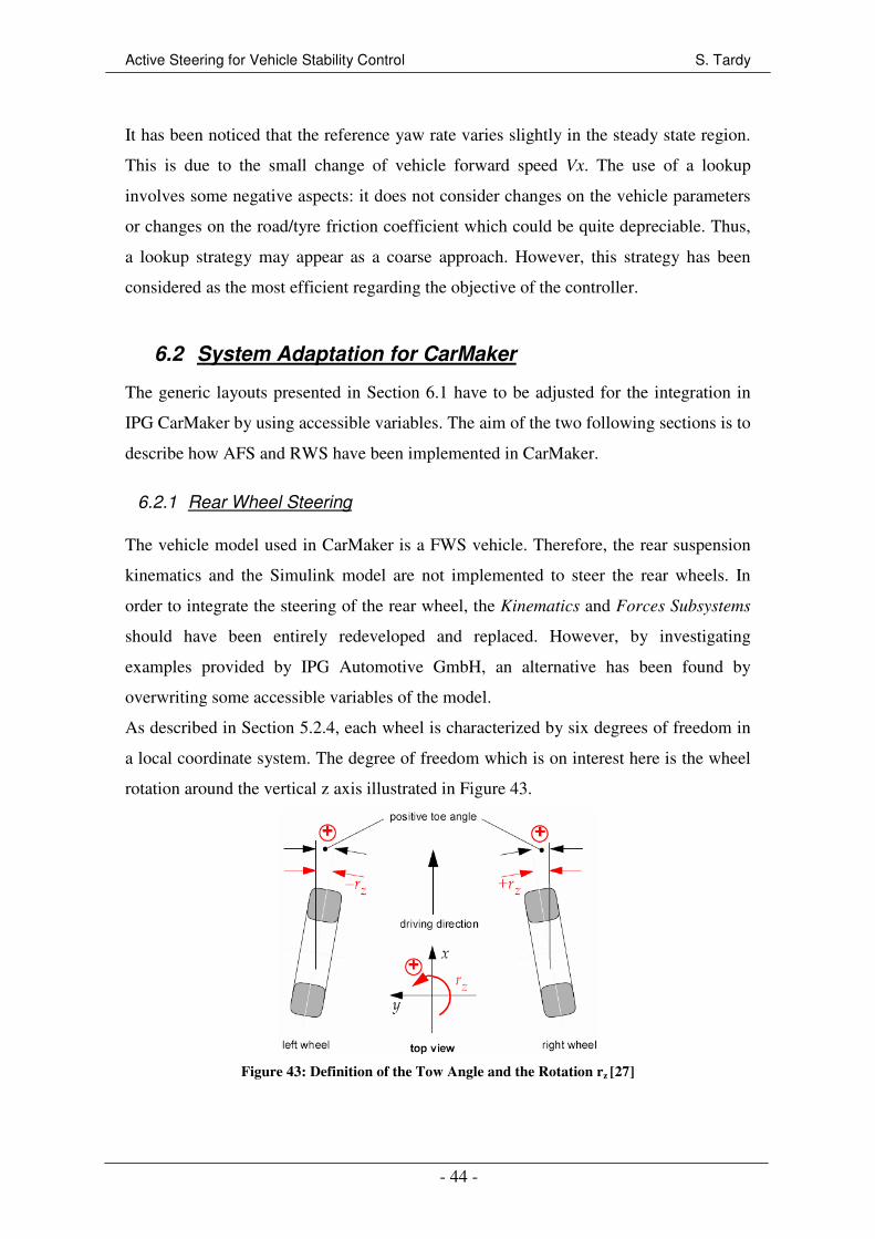
Active Steering for Vehicle Stability Control S. Tardy
- 44 -
It has been noticed that the reference yaw rate varies slightly in the steady state region.
This is due to the small change of vehicle forward speed Vx. The use of a lookup
involves some negative aspects: it does not consider changes on the vehicle parameters
or changes on the road/tyre friction coefficient which could be quite depreciable. Thus,
a lookup strategy may appear as a coarse approach. However, this strategy has been
considered as the most efficient regarding the objective of the controller.
6.2 System Adaptation for CarMaker
The generic layouts presented in Section 6.1 have to be adjusted for the integration in
IPG CarMaker by using accessible variables. The aim of the two following sections is to
describe how AFS and RWS have been implemented in CarMaker.
6.2.1 Rear Wheel Steering
The vehicle model used in CarMaker is a FWS vehicle. Therefore, the rear suspension
kinematics and the Simulink model are not implemented to steer the rear wheels. In
order to integrate the steering of the rear wheel, the Kinematics and Forces Subsystems
should have been entirely redeveloped and replaced. However, by investigating
examples provided by IPG Automotive GmbH, an alternative has been found by
overwriting some accessible variables of the model.
As described in Section 5.2.4, each wheel is characterized by six degrees of freedom in
a local coordinate system. The degree of freedom which is on interest here is the wheel
rotation around the vertical z axis illustrated in Figure 43.
Figure 43: Definition of the Tow Angle and the Rotation rz [27]

Active Steering for Vehicle Stability Control S. Tardy
- 45 -
The orientation rz of the wheel around this axis is compounded of three independent
components: a kinematics component which included the toe angle and the movements
due to the suspension and the steering system, a compliance component, and an external
component which can be used for the user to influence the orientation of the wheels.
This external component is zero as a default value. The steering of the rear wheels was
implemented in the CarMaker model by overwriting this external component as shown
in Figure 44.
Figure 44: RWS Implementation in the CarMaker Model
The RWS yaw moment controller layout is given in Figure 45. Note that as the toe
angle is included in the kinematics component, an average of the front left –
Car.CFL.rz_kin – and front right – Car.CFL.rz_kin – wheel orientation was used to
estimate the front steer angle. The vehicle yaw rate Car.YawRate and the forward speed
Car.vx were also measured. A “Switch” block was used to able the active system to
operate only above 15 m/s.
Figure 45: CarMaker Yaw Moment Controller Layout for RWS
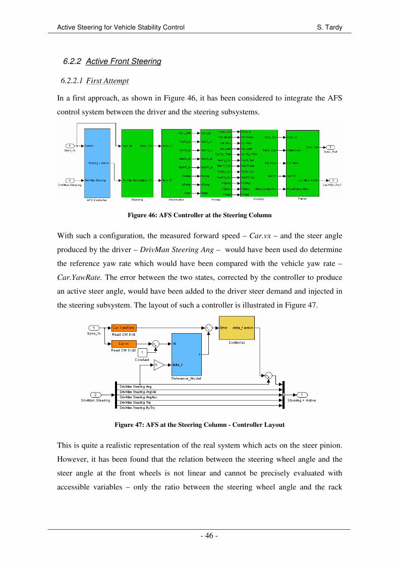
Active Steering for Vehicle Stability Control S. Tardy
- 46 -
6.2.2 Active Front Steering
6.2.2.1 First Attempt
In a first approach, as shown in Figure 46, it has been considered to integrate the AFS
control system between the driver and the steering subsystems.
Figure 46: AFS Controller at the Steering Column
With such a configuration, the measured forward speed – Car.vx – and the steer angle
produced by the driver – DrivMan Steering Ang – would have been used do determine
the reference yaw rate which would have been compared with the vehicle yaw rate –
Car.YawRate. The error between the two states, corrected by the controller to produce
an active steer angle, would have been added to the driver steer demand and injected in
the steering subsystem. The layout of such a controller is illustrated in Figure 47.
Figure 47: AFS at the Steering Column - Controller Layout
This is quite a realistic representation of the real system which acts on the steer pinion.
However, it has been found that the relation between the steering wheel angle and the
steer angle at the front wheels is not linear and cannot be precisely evaluated with
accessible variables – only the ratio between the steering wheel angle and the rack
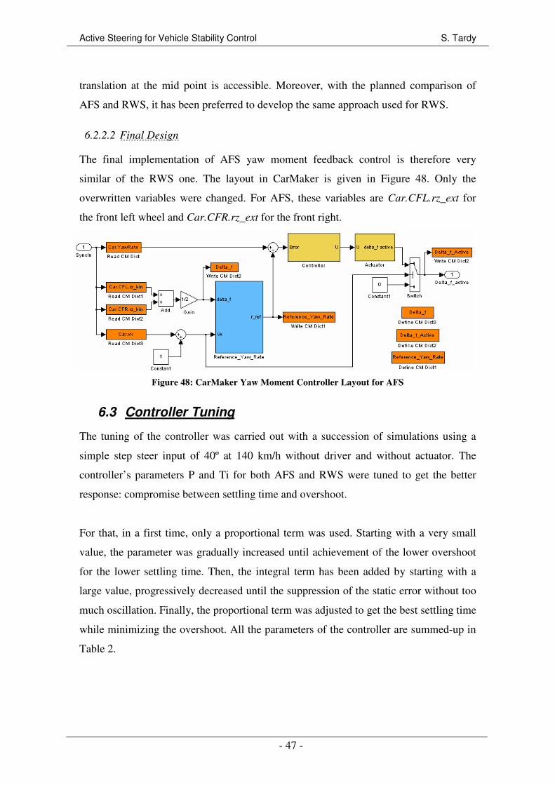
Active Steering for Vehicle Stability Control S. Tardy
- 47 -
translation at the mid point is accessible. Moreover, with the planned comparison of
AFS and RWS, it has been preferred to develop the same approach used for RWS.
6.2.2.2 Final Design
The final implementation of AFS yaw moment feedback control is therefore very
similar of the RWS one. The layout in CarMaker is given in Figure 48. Only the
overwritten variables were changed. For AFS, these variables are Car.CFL.rz_ext for
the front left wheel and Car.CFR.rz_ext for the front right.
Figure 48: CarMaker Yaw Moment Controller Layout for AFS
6.3 Controller Tuning
The tuning of the controller was carried out with a succession of simulations using a
simple step steer input of 40º at 140 km/h without driver and without actuator. The
controller’s parameters P and Ti for both AFS and RWS were tuned to get the better
response: compromise between settling time and overshoot.
For that, in a first time, only a proportional term was used. Starting with a very small
value, the parameter was gradually increased until achievement of the lower overshoot
for the lower settling time. Then, the integral term has been added by starting with a
large value, progressively decreased until the suppression of the static error without too
much oscillation. Finally, the proportional term was adjusted to get the best settling time
while minimizing the overshoot. All the parameters of the controller are summed-up in
Table 2.
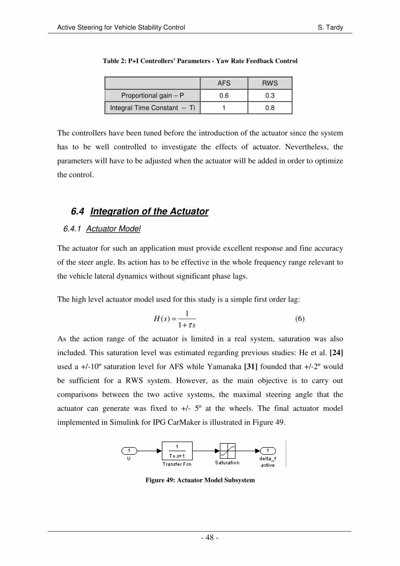
Active Steering for Vehicle Stability Control S. Tardy
- 48 -
Table 2: P+I Controllers’ Parameters - Yaw Rate Feedback Control
AFS RWS
Proportional gain – P 0.6 0.3
Integral Time Constant – Ti 1 0.8
The controllers have been tuned before the introduction of the actuator since the system
has to be well controlled to investigate the effects of actuator. Nevertheless, the
parameters will have to be adjusted when the actuator will be added in order to optimize
the control.
6.4 Integration of the Actuator
6.4.1 Actuator Model
The actuator for such an application must provide excellent response and fine accuracy
of the steer angle. Its action has to be effective in the whole frequency range relevant to
the vehicle lateral dynamics without significant phase lags.
The high level actuator model used for this study is a simple first order lag:
1( )
1H s
sτ=
+ (6)
As the action range of the actuator is limited in a real system, saturation was also
included. This saturation level was estimated regarding previous studies: He et al. [24]
used a +/-10º saturation level for AFS while Yamanaka [31] founded that +/-2º would
be sufficient for a RWS system. However, as the main objective is to carry out
comparisons between the two active systems, the maximal steering angle that the
actuator can generate was fixed to +/- 5º at the wheels. The final actuator model
implemented in Simulink for IPG CarMaker is illustrated in Figure 49.
Figure 49: Actuator Model Subsystem

Active Steering for Vehicle Stability Control S. Tardy
- 49 -
6.4.2 Influence of the Bandwidth
The bandwidth of an actuator is very often the limiting parameter which could
considerably impair the performance of the system. Previous studies on RWS actuators
[31] have shown that an acceptable bandwidth should be between 2 and 6 Hz. The
influence of the actuator bandwidth on the systems responses were so analyzed in this
range of frequency for the system without and with driver.
6.4.2.1 Bandwidth Analysis Without Driver in the Loop
The system used for this study is AFS; the results would have been similar with RWS.
The parameters of the controller which have been optimized for the system without
actuator were kept constant. The test consisted of a step steering wheel input of 40º - i.e.
0.035 rad steer angle at the front wheels, at a constant forward velocity of 140 km/h.
The driver was not included in the system, it was a pure step applied at the steering
wheel. Figure 50 shows yaw rate and corrective steer angle time responses for the AFS
system without actuator, and with actuator for three different bandwidths. A zoom has
been applied to the graph for a better visualization, the step steer demand starts however
at t=0s. Note that the overall responses and performance of AFS and RWS will be
discussed and compared later with the passive vehicle.
(a)
(b)
Figure 50: Actuator Bandwidth Influence - Step Steer Input
The influence of the actuator bandwidth is noticeable: the overshoot in the yaw rate
response (a) for the system with a 2 Hz bandwidth actuator is 10.8% while it is 9.4% for
the response without actuator. That corresponds to an overshoot increasing of 17%. It

Active Steering for Vehicle Stability Control S. Tardy
- 50 -
can also be noticed that the lower the bandwidth is, the more the response is oscillatory
and so the more the stability of the system is damaged. Moreover, low bandwidth is
synonymous with higher actuator work load – Figure 50 (b), and so a high energy
consumption. Therefore, the actuator does not have to have a too low bandwidth. It has
been also noticed that a high bandwidth – e.g. 15 Hz – would not give much better yaw
rate response than a 6 Hz bandwidth while a high frequency actuator would involve
high performance components and so high cost. Therefore, a bandwidth of 4 Hz was
chosen for the continuation of the study; it is a compromise between performance and
actuator feasibility.
6.4.2.2 Bandwidth Analysis With Driver in the Loop
The previous section has shown that the actuator bandwidth without the driver in the
loop could impair the vehicle response. In this section, the influence of the bandwidth is
investigated when the driver is part of the system.
6.4.2.2.1 Simple Driver Model
Firstly, a simple driver model which only follows a desired path was integrated. In this
sense, the driver does not consider any torque feedback form the steering system and
any feeling he could have – e.g. high lateral acceleration or sliding of the vehicle – to
adjust the steering wheel input. The path which had to be followed was simple and
matched the step steer demand analyzed in Section 6.4.2.1. It is a 400 m straight line
plus a 200 m radius bend. The vehicle accelerates in the straight line from 0 km/h to
reach a cruise speed of 140 km/h before entering in the curve. The actuator bandwidth
was set to 4 Hz, the controller’s parameters were the same as before. The reading of the
yaw rate time response – Figure 51 – shows that a basic driver model has no unwanted
influence on the system and does not interact unfavourably with the actuator.
6.4.2.2.2 Advanced Driver Model
Then, a more advanced and realistic driver model was integrated. This optimized model
considers for example the torque feedback given by the steering system, a maximal
lateral acceleration – 4 m/s2, or a limit sideslip angle – 11.028º. The model also includes
driver’s knowledge about the vehicle behaviour and an algorithm which allows the
driver to learn about the vehicle response. An example illustrating the difference
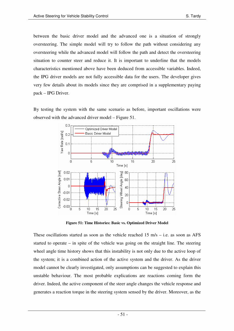
Active Steering for Vehicle Stability Control S. Tardy
- 51 -
between the basic driver model and the advanced one is a situation of strongly
oversteering. The simple model will try to follow the path without considering any
oversteering while the advanced model will follow the path and detect the oversteering
situation to counter steer and reduce it. It is important to underline that the models
characteristics mentioned above have been deduced from accessible variables. Indeed,
the IPG driver models are not fully accessible data for the users. The developer gives
very few details about its models since they are comprised in a supplementary paying
pack – IPG Driver.
By testing the system with the same scenario as before, important oscillations were
observed with the advanced driver model – Figure 51.
Figure 51: Time Histories: Basic vs. Optimized Driver Model
These oscillations started as soon as the vehicle reached 15 m/s – i.e. as soon as AFS
started to operate – in spite of the vehicle was going on the straight line. The steering
wheel angle time history shows that this instability is not only due to the active loop of
the system; it is a combined action of the active system and the driver. As the driver
model cannot be clearly investigated, only assumptions can be suggested to explain this
unstable behaviour. The most probable explications are reactions coming form the
driver. Indeed, the active component of the steer angle changes the vehicle response and
generates a reaction torque in the steering system sensed by the driver. Moreover, as the
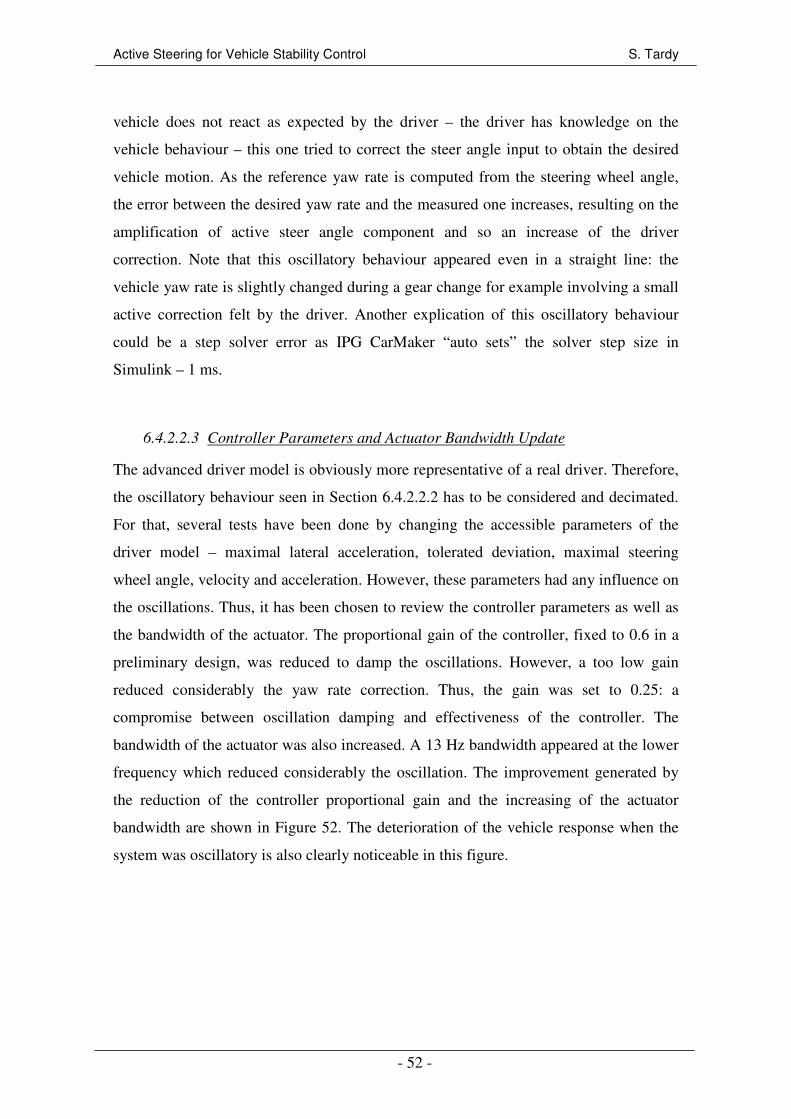
Active Steering for Vehicle Stability Control S. Tardy
- 52 -
vehicle does not react as expected by the driver – the driver has knowledge on the
vehicle behaviour – this one tried to correct the steer angle input to obtain the desired
vehicle motion. As the reference yaw rate is computed from the steering wheel angle,
the error between the desired yaw rate and the measured one increases, resulting on the
amplification of active steer angle component and so an increase of the driver
correction. Note that this oscillatory behaviour appeared even in a straight line: the
vehicle yaw rate is slightly changed during a gear change for example involving a small
active correction felt by the driver. Another explication of this oscillatory behaviour
could be a step solver error as IPG CarMaker “auto sets” the solver step size in
Simulink – 1 ms.
6.4.2.2.3 Controller Parameters and Actuator Bandwidth Update
The advanced driver model is obviously more representative of a real driver. Therefore,
the oscillatory behaviour seen in Section 6.4.2.2.2 has to be considered and decimated.
For that, several tests have been done by changing the accessible parameters of the
driver model – maximal lateral acceleration, tolerated deviation, maximal steering
wheel angle, velocity and acceleration. However, these parameters had any influence on
the oscillations. Thus, it has been chosen to review the controller parameters as well as
the bandwidth of the actuator. The proportional gain of the controller, fixed to 0.6 in a
preliminary design, was reduced to damp the oscillations. However, a too low gain
reduced considerably the yaw rate correction. Thus, the gain was set to 0.25: a
compromise between oscillation damping and effectiveness of the controller. The
bandwidth of the actuator was also increased. A 13 Hz bandwidth appeared at the lower
frequency which reduced considerably the oscillation. The improvement generated by
the reduction of the controller proportional gain and the increasing of the actuator
bandwidth are shown in Figure 52. The deterioration of the vehicle response when the
system was oscillatory is also clearly noticeable in this figure.

Active Steering for Vehicle Stability Control S. Tardy
- 53 -
Figure 52: Time Histories: Bandwidth and Controller Tuning
It is important to be aware that a 13 Hz bandwidth is high for such an actuator
particularly regarding the bandwidth used in other studies. However, most of the studies
carried out on AFS or RWS used a simple driver models to track a desired path. Thus,
the undesirable interaction between the driver and the actuator was probably not
visualized.
Finally, it has to be said that this study on the actuator was necessary before any
performance evaluation because, as it has been seen, the actuator and the driver
interaction would have spoiled considerably the performance.
6.4.2.2.4 Considerations for RWS
The previous study has been carried out for AFS, nevertheless, the approach is similar
for RWS. Oscillations were also observable with the advanced driver model, but these
oscillations were lower than for AFS. The most probable explication is that the torque
feedback at the steering wheel is much more less than for AFS since the steer angle
correction is applied at the rear wheels. However, the driver feeling remains and
generates oscillations. With the same approach as for AFS, the controller proportional
gain was reduced from 0.3 to 0.08 for RWS. An actuator bandwidth of 8 Hz would have

Active Steering for Vehicle Stability Control S. Tardy
- 54 -
been sufficient, however to compare AFS and RWS, the RWS actuator bandwidth was
also set to 13 Hz.
As a short reminder, the updated controller parameters for AFS and RWS are given in
Table 3.
Table 3: P+I Controllers’ Parameters after Actuator Integration - Yaw Rate Feedback Control
AFS RWS
Proportional gain – P 0.25 0.08
Integral Time Constant – Ti 1 0.8
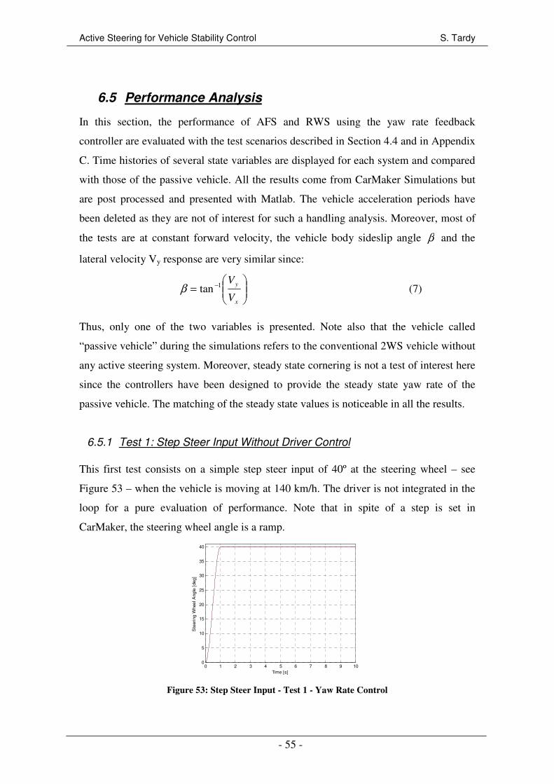
Active Steering for Vehicle Stability Control S. Tardy
- 55 -
6.5 Performance Analysis
In this section, the performance of AFS and RWS using the yaw rate feedback
controller are evaluated with the test scenarios described in Section 4.4 and in Appendix
C. Time histories of several state variables are displayed for each system and compared
with those of the passive vehicle. All the results come from CarMaker Simulations but
are post processed and presented with Matlab. The vehicle acceleration periods have
been deleted as they are not of interest for such a handling analysis. Moreover, most of
the tests are at constant forward velocity, the vehicle body sideslip angle β and the
lateral velocity Vy response are very similar since:
= −
x
y
V
V1tanβ (7)
Thus, only one of the two variables is presented. Note also that the vehicle called
“passive vehicle” during the simulations refers to the conventional 2WS vehicle without
any active steering system. Moreover, steady state cornering is not a test of interest here
since the controllers have been designed to provide the steady state yaw rate of the
passive vehicle. The matching of the steady state values is noticeable in all the results.
6.5.1 Test 1: Step Steer Input Without Driver Control
This first test consists on a simple step steer input of 40º at the steering wheel – see
Figure 53 – when the vehicle is moving at 140 km/h. The driver is not integrated in the
loop for a pure evaluation of performance. Note that in spite of a step is set in
CarMaker, the steering wheel angle is a ramp.
0 1 2 3 4 5 6 7 8 9 100
5
10
15
20
25
30
35
40
Time [s]
Ste
erin
g W
heel
Ang
le [
deg]
Figure 53: Step Steer Input - Test 1 - Yaw Rate Control

Active Steering for Vehicle Stability Control S. Tardy
- 56 -
Time histories of yaw rate (a), vehicle body sideslip angle (b), lateral acceleration (c)
and active steer angle (d) are given in Figure 54 for the passive, AFS and RWS
vehicles. Both AFS and RWS improve the vehicle stability during the transient
response. Indeed, the overshoot percentage in the yaw rate response is reduced from
39.4% – passive vehicle – to 18% for AFS and to 29% for RWS. The yaw rate settling
time – initially 3.43 s for the passive vehicle – is also reduced: by 60% for AFS and
32% for RWS. It has also to be noticed that one target of the controller is achieved: the
steady state behaviour of the active vehicles is identical as the one of the passive
vehicle.
0 1 2 3 4 5 6 7 8 9 100
0.05
0.1
0.15
0.2
0.25
0.3
Time [s]
Yaw
Rat
e [r
ad/s
]
Passive
AFS
RWS
Reference Yaw Rate
0 1 2 3 4 5 6 7 8 9 10-0.08
-0.07
-0.06
-0.05
-0.04
-0.03
-0.02
-0.01
0
Time [s]
Veh
icle
Bod
y S
ides
lip A
ngle
[ra
d]
Passive
AFSRWS
0 1 2 3 4 5 6 7 8 9 100
1
2
3
4
5
6
7
8
9
Time [s]
Late
ral A
ccel
erat
ion
[m/s
2 ]
Passive
AFS
RWS
0 1 2 3 4 5 6 7 8 9 10
-10
-8
-6
-4
-2
0
2
4
6
x 10-3
Time [s]
Act
ive
Ste
er A
ngle
[ra
d]
AFS
RWS
Figure 54: Time Histories - Test 1 - Yaw Rate Control
Higher damping and lower settling time on the lateral acceleration as well as in the body
sideslip angle responses are also noticeable. Moreover, AFS and RWS subtended area
in sideslip phase plane - Figure 56 - are much more less than the passive vehicle. It
means that the two active vehicles produce less sideslip and more slowly, thus they are
more stable.
(c) (d)
(b) (a)
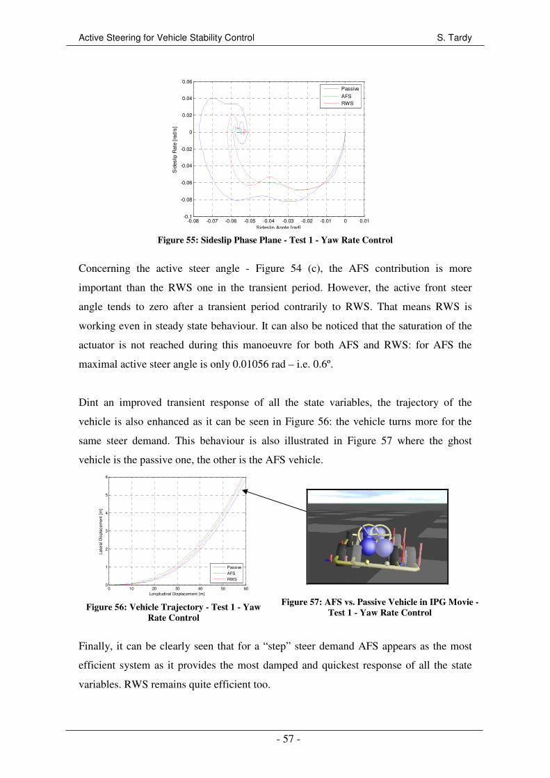
Active Steering for Vehicle Stability Control S. Tardy
- 57 -
-0.08 -0.07 -0.06 -0.05 -0.04 -0.03 -0.02 -0.01 0 0.01-0.1
-0.08
-0.06
-0.04
-0.02
0
0.02
0.04
0.06
Sideslip Angle [rad]
Sid
eslip
Rat
e [r
ad/s
]
Passive
AFSRWS
Figure 55: Sideslip Phase Plane - Test 1 - Yaw Rate Control
Concerning the active steer angle - Figure 54 (c), the AFS contribution is more
important than the RWS one in the transient period. However, the active front steer
angle tends to zero after a transient period contrarily to RWS. That means RWS is
working even in steady state behaviour. It can also be noticed that the saturation of the
actuator is not reached during this manoeuvre for both AFS and RWS: for AFS the
maximal active steer angle is only 0.01056 rad – i.e. 0.6º.
Dint an improved transient response of all the state variables, the trajectory of the
vehicle is also enhanced as it can be seen in Figure 56: the vehicle turns more for the
same steer demand. This behaviour is also illustrated in Figure 57 where the ghost
vehicle is the passive one, the other is the AFS vehicle.
Finally, it can be clearly seen that for a “step” steer demand AFS appears as the most
efficient system as it provides the most damped and quickest response of all the state
variables. RWS remains quite efficient too.
0 10 20 30 40 50 600
1
2
3
4
5
6
Longitudinal Displacement [m]
Late
ral D
ispl
acem
ent
[m]
Passive
AFS
RWS
Figure 56: Vehicle Trajectory - Test 1 - Yaw
Rate Control
Figure 57: AFS vs. Passive Vehicle in IPG Movie -
Test 1 - Yaw Rate Control
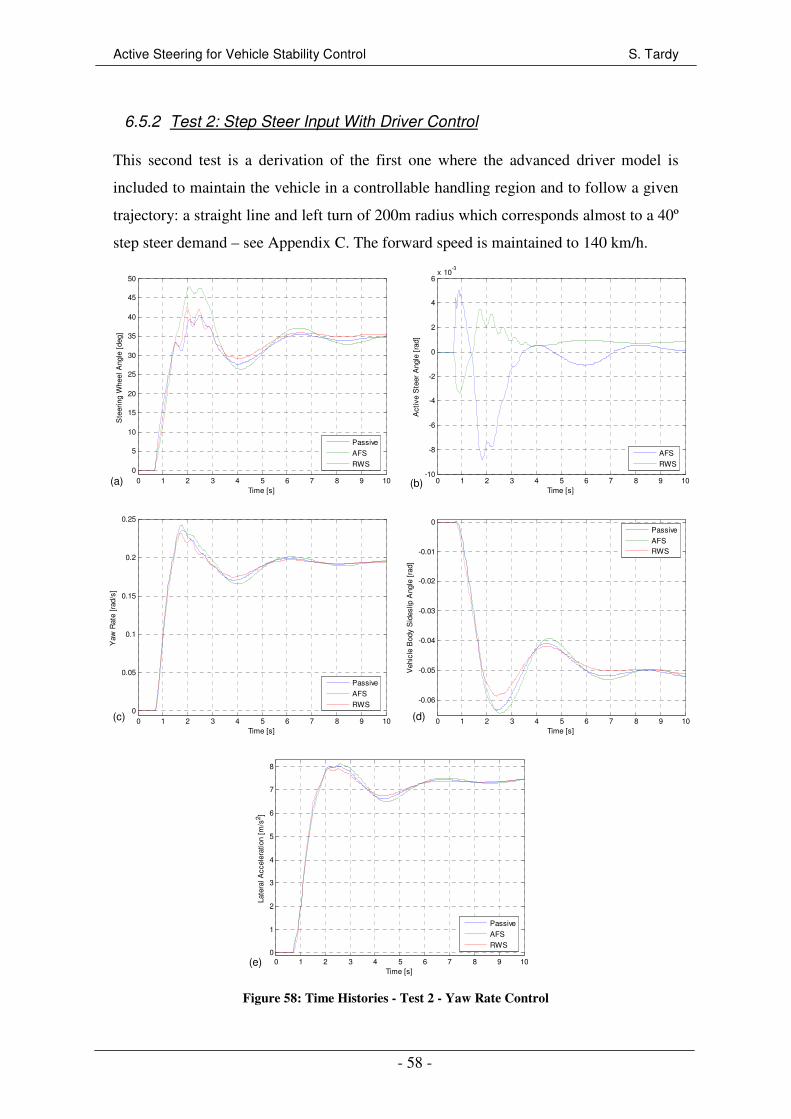
Active Steering for Vehicle Stability Control S. Tardy
- 58 -
6.5.2 Test 2: Step Steer Input With Driver Control
This second test is a derivation of the first one where the advanced driver model is
included to maintain the vehicle in a controllable handling region and to follow a given
trajectory: a straight line and left turn of 200m radius which corresponds almost to a 40º
step steer demand – see Appendix C. The forward speed is maintained to 140 km/h.
0 1 2 3 4 5 6 7 8 9 100
5
10
15
20
25
30
35
40
45
50
Time [s]
Ste
erin
g W
heel
Ang
le [
deg]
Passive
AFS
RWS
0 1 2 3 4 5 6 7 8 9 10-10
-8
-6
-4
-2
0
2
4
6x 10
-3
Time [s]
Act
ive
Ste
er A
ngle
[ra
d]
AFS
RWS
0 1 2 3 4 5 6 7 8 9 100
0.05
0.1
0.15
0.2
0.25
Time [s]
Yaw
Rat
e [r
ad/s
]
Passive
AFS
RWS
0 1 2 3 4 5 6 7 8 9 10
-0.06
-0.05
-0.04
-0.03
-0.02
-0.01
0
Time [s]
Veh
icle
Bod
y S
ides
lip A
ngle
[ra
d]
Passive
AFSRWS
0 1 2 3 4 5 6 7 8 9 100
1
2
3
4
5
6
7
8
Time [s]
Late
ral A
ccel
erat
ion
[m/s
2 ]
Passive
AFS
RWS
Figure 58: Time Histories - Test 2 - Yaw Rate Control
(a) (b)
(c) (d)
(e)
Active Steering for Vehicle Stability Control S. Tardy
- 59 -
Figure 58 represents a history comparison between passive vehicle, AFS vehicle and the
RWS vehicle for the steering wheel (a) and active steer (b) angles, the yaw rate (c), the
vehicle body sideslip angle (d), and the lateral acceleration (e). It can be noticed that the
AFS vehicle provides the most oscillatory responses: the peak to peak amplitude is
0.063 rad/s for the passive vehicle, 0.57 for RWS and 0.074 for AFS. The AFS system
adds also a delay in the lateral acceleration response – maximal delay of 0.4 s. This
deterioration of the response is due to a reaction between the driver and the active
system. Indeed, after t=1.5 s, the active steer angle components becomes negative to
correct the yaw rate response and reduces the steer angle at the wheels. However,
feeling the understeering, the driver increases his demand to follow the path and so
works against the active system. That explains peaks in steering wheel and active steer
angles around t=2s.
In counterpart, RWS provides improvement of the vehicle stability. Indeed, the vehicle
body sideslip angle - Figure 58 (e) - is more damped than the passive vehicle.
Moreover, after 6 s the driver does not have to provide any steering action for RWS
while he has to steer until more than 10 s for the passive or AFS vehicles. This
translates a decreasing of the driver work load, in other words an increasing of the
driver comfort.
Finally, in comparison to the step steer input test without driver, this second test shows
the importance of the driver feeling and feedback. AFS was the most efficient system
without driver, but could generate undesirable effects if the driver works against the
active system.
6.5.3 Test 3: Accelerating and Turning
This third test is an acceleration of 1.7 m/s2 from 100 km/h while the driver has to
follow a curve of 200m radius. This test characterizes the controller performance close
to the handling limit. It could also represent a highway entrance where the driver has to
run-up in a turn.
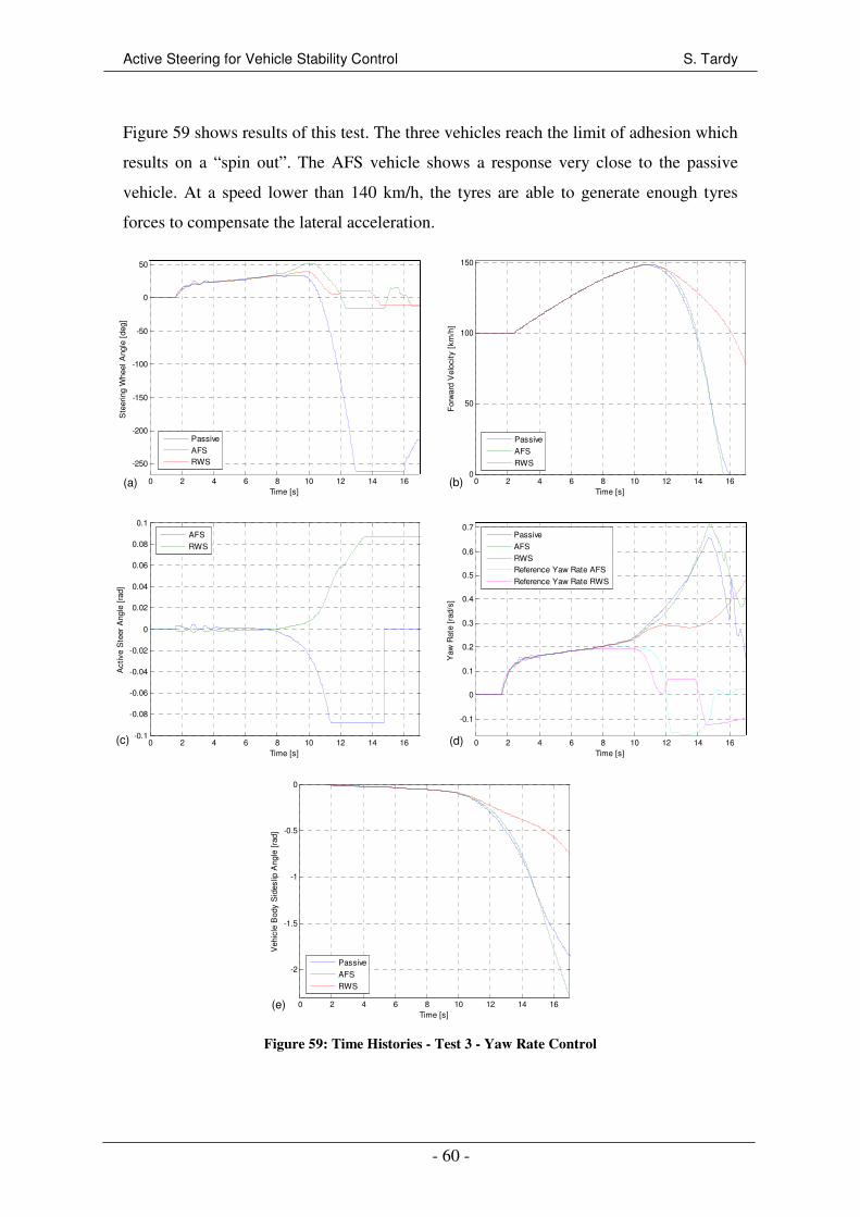
Active Steering for Vehicle Stability Control S. Tardy
- 60 -
Figure 59 shows results of this test. The three vehicles reach the limit of adhesion which
results on a “spin out”. The AFS vehicle shows a response very close to the passive
vehicle. At a speed lower than 140 km/h, the tyres are able to generate enough tyres
forces to compensate the lateral acceleration.
0 2 4 6 8 10 12 14 16
-250
-200
-150
-100
-50
0
50
Time [s]
Ste
erin
g W
heel
Ang
le [
deg]
Passive
AFSRWS
0 2 4 6 8 10 12 14 160
50
100
150
Time [s]
For
war
d V
eloc
ity [
km/h
]Passive
AFS
RWS
0 2 4 6 8 10 12 14 16-0.1
-0.08
-0.06
-0.04
-0.02
0
0.02
0.04
0.06
0.08
0.1
Time [s]
Act
ive
Ste
er A
ngle
[ra
d]
AFS
RWS
0 2 4 6 8 10 12 14 16
-0.1
0
0.1
0.2
0.3
0.4
0.5
0.6
0.7
Time [s]
Yaw
Rat
e [r
ad/s
]
Passive
AFS
RWSReference Yaw Rate AFS
Reference Yaw Rate RWS
0 2 4 6 8 10 12 14 16
-2
-1.5
-1
-0.5
0
Time [s]
Veh
icle
Bod
y S
ides
lip A
ngle
[ra
d]
Passive
AFS
RWS
Figure 59: Time Histories - Test 3 - Yaw Rate Control
(a) (b)
(c) (d)
(e)

Active Steering for Vehicle Stability Control S. Tardy
- 61 -
However, when the speed becomes more than 140 km/h, the three vehicles starts to
oversteer as it can be seen in the yaw rate response (d). Since the vehicle is rear wheel
drive, a part of the rear tyre performance is used longitudinally for the acceleration.
Thus, the rear tyres are more stirred up than the front ones and so become saturated
before, resulting on an oversteering situation. The driver starts then to counter steer -
negative steer angle - to correct this oversteering. The two active systems reduce
considerably the driver work (a) during this counter steer action – 77% less for AFS and
98% for RWS. However, the two active steering actuators (c) get saturated and cannot
support the driver anymore involving the loss of control – “drop” of the body sideslip
angle (e).
In spite of the three vehicles span out, RWS shows better abilities to maintain the
vehicle under control. Indeed, as shown in Figure 60, while the passive vehicle is totally
out of control, the RWS one is still stable despite an important oversteering behaviour.
This is also noticeable on all the time responses where, at high speed, the state variables
for RWS are much lower than the passive or the AFS vehicle. The sideslip angle rate is
also much lower when RWS is used – see Figure 61. This is explained by a better
management of the rear tyre forces: by turning the rear wheels, the rear tyre lateral
forces are decreased due to a lower body sideslip angle.
Figure 60: RWS vs. Passive Vehicle in IPG
Movie - Test 3 - Yaw Rate Control
-2.5 -2 -1.5 -1 -0.5 0
-0.9
-0.8
-0.7
-0.6
-0.5
-0.4
-0.3
-0.2
-0.1
0
Sideslip Angle [rad]
Sid
eslip
Rat
e [r
ad/s
]
Passive
AFSRWS
Figure 61: Sideslip Phase Plane - Test 3 - Yaw
Rate Control

Active Steering for Vehicle Stability Control S. Tardy
- 62 -
6.5.4 Test 4: Braking and Turning
This common test is a hard braking manoeuvre combined to a severe turning aiming to
represent an emergency manoeuvre like collision avoidance. As shown in Figure 62, the
step steering wheel input is set to 50º (a), the hard braking involves a deceleration about
1.01g (b) from an initial speed of 140 km/h.
0 1 2 3 4 5 6 7 80
5
10
15
20
25
30
35
40
45
50
Time [s]
Ste
erin
g W
heel
Ang
le [
deg]
0 1 2 3 4 5 6 7 80
20
40
60
80
100
120
140
Time [s]
For
war
d S
peed
[km
/h]
Figure 62: Steering Wheel Angle and Forward Velocity - Test 4 - Yaw Rate Control
Regarding the yaw rate (a), body sideslip angle (b) and lateral acceleration (c) responses
in Figure 63, it can be seen that the active systems increase the state variables
particularly when the vehicle passes under 100 km/h. For example at 60 km/h, the AFS
yaw rate is increased by almost 0.05 rad/s by comparing with the passive vehicle. This
is advantageous for such a manoeuvre where the lateral displacement is more important
than the driver comfort. It is also interesting to notice that AFS and RWS respond
quicker since the yaw rates and lateral accelerations are established slightly before the
passive vehicle – 0.09 s for AFS and 0.06 s for RWS. The active systems cannot
achieve the reference yaw rate since both tyres and actuators become saturated.
(a) (b)
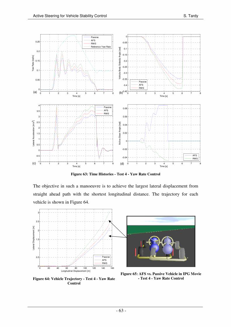
Active Steering for Vehicle Stability Control S. Tardy
- 63 -
0 1 2 3 4 5 6 7 8
0
0.05
0.1
0.15
0.2
0.25
Time [s]
Yaw
Rat
e [r
ad/s
]
Passive
AFS
RWS
Reference Yaw Rate
0 1 2 3 4 5 6 7 8-0.45
-0.4
-0.35
-0.3
-0.25
-0.2
-0.15
-0.1
-0.05
0
Time [s]
Veh
icle
Bod
y S
ides
lip A
ngle
[ra
d]
Passive
AFS
RWS
0 1 2 3 4 5 6 7 8-1
-0.5
0
0.5
1
1.5
2
2.5
3
3.5
4
Time [s]
Late
ral A
ccel
erat
ion
[m/s
2 ]
Passive
AFS
RWS
0 1 2 3 4 5 6 7 8
-0.04
-0.02
0
0.02
0.04
0.06
0.08
Time [s]
Act
ive
Ste
er A
ngle
[ra
d]
AFS
RWS
Figure 63: Time Histories - Test 4 - Yaw Rate Control
The objective in such a manoeuvre is to achieve the largest lateral displacement from
straight ahead path with the shortest longitudinal distance. The trajectory for each
vehicle is shown in Figure 64.
0 20 40 60 80 100 120 140 1600
0.5
1
1.5
2
2.5
3
Longitudinal Displacement [m]
Late
ral D
ispl
acem
ent
[m]
Passive
AFS
RWS
Figure 64: Vehicle Trajectory - Test 4 - Yaw Rate
Control
Figure 65: AFS vs. Passive Vehicle in IPG Movie
- Test 4 - Yaw Rate Control
(a) (b)
(c) (d)
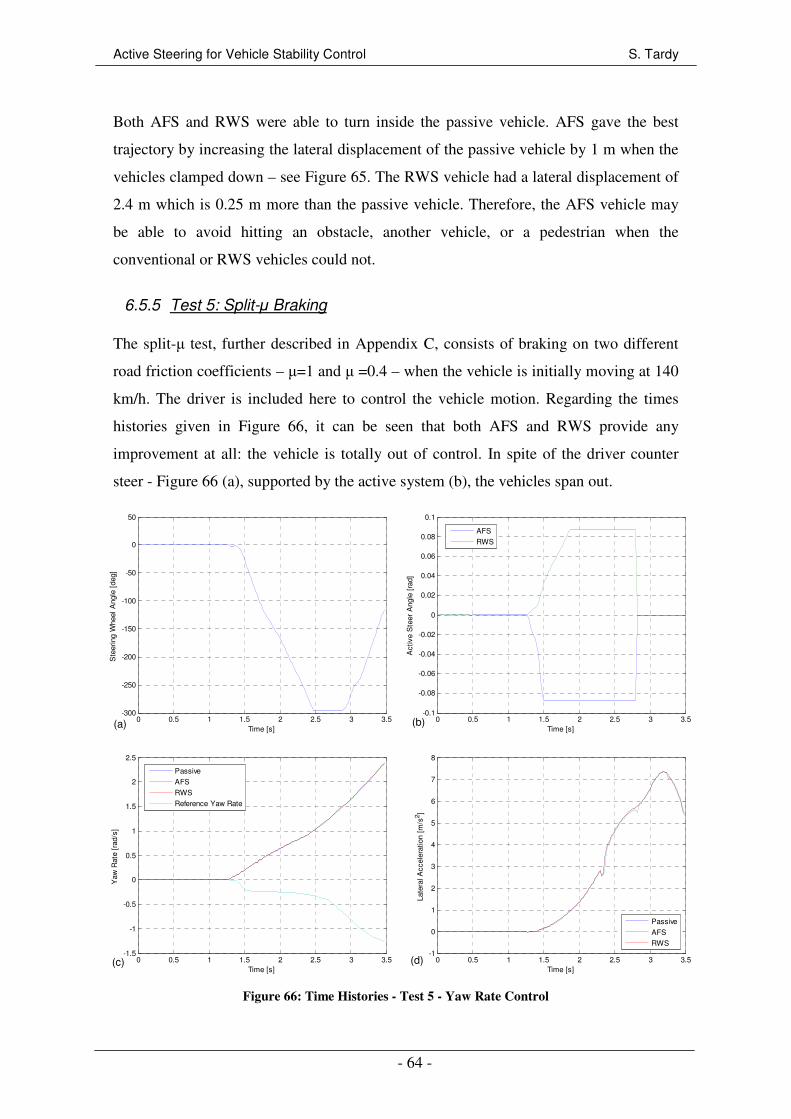
Active Steering for Vehicle Stability Control S. Tardy
- 64 -
Both AFS and RWS were able to turn inside the passive vehicle. AFS gave the best
trajectory by increasing the lateral displacement of the passive vehicle by 1 m when the
vehicles clamped down – see Figure 65. The RWS vehicle had a lateral displacement of
2.4 m which is 0.25 m more than the passive vehicle. Therefore, the AFS vehicle may
be able to avoid hitting an obstacle, another vehicle, or a pedestrian when the
conventional or RWS vehicles could not.
6.5.5 Test 5: Split-µ Braking
The split-µ test, further described in Appendix C, consists of braking on two different
road friction coefficients – µ=1 and µ =0.4 – when the vehicle is initially moving at 140
km/h. The driver is included here to control the vehicle motion. Regarding the times
histories given in Figure 66, it can be seen that both AFS and RWS provide any
improvement at all: the vehicle is totally out of control. In spite of the driver counter
steer - Figure 66 (a), supported by the active system (b), the vehicles span out.
0 0.5 1 1.5 2 2.5 3 3.5-300
-250
-200
-150
-100
-50
0
50
Time [s]
Ste
erin
g W
heel
Ang
le [
deg]
0 0.5 1 1.5 2 2.5 3 3.5-0.1
-0.08
-0.06
-0.04
-0.02
0
0.02
0.04
0.06
0.08
0.1
Time [s]
Act
ive
Ste
er A
ngle
[ra
d]
AFS
RWS
0 0.5 1 1.5 2 2.5 3 3.5-1.5
-1
-0.5
0
0.5
1
1.5
2
2.5
Time [s]
Yaw
Rat
e [r
ad/s
]
Passive
AFS
RWS
Reference Yaw Rate
0 0.5 1 1.5 2 2.5 3 3.5-1
0
1
2
3
4
5
6
7
8
Time [s]
Late
ral A
ccel
erat
ion
[m/s
2 ]
Passive
AFS
RWS
Figure 66: Time Histories - Test 5 - Yaw Rate Control
(a) (b)
(c) (d)

Active Steering for Vehicle Stability Control S. Tardy
- 65 -
The total failing of the active systems is easily interpretable. The tyres in the low
friction side generate much lower lateral and longitudinal forces than the high adhesion
side and so an important yaw moment is created. The yaw rate controller acts by turning
the front or the rear wheels to correct this yaw moment, however one side cannot
generate the amount of forces needed; only half of the controller demand can be
generated. This engenders the controller to ask more and so saturates the actuators as
well as the tyres in the high µ side. Note that in such a situation, the loss of control is
mainly due to the longitudinal tyre saturation which could be hardly managed by
working on the lateral forces in opposition to ABS which aims to manage the
longitudinal forces.
6.5.6 Double Lane Change
Double lane change is a transient manoeuvres that drivers experience regularly. It is a
challenging manoeuvre both from vehicle dynamics and driver’s point of view as the
vehicle changes suddenly from understeer to a limit oversteering condition. Two double
lane change test were carried out, the first one is an ISO test at 100 km/h, and the
second is done at 140 km/h. Details about the tests’ configurations are enclosed in
Appendix C.
6.5.6.1 Test 6: ISO Double Lane Change
Results of the ISO test – Figure 67 – show that both AFS and RWS improve the vehicle
response. The state variables are reduced all along the manoeuvre. The improvement
due to the active systems appears particularly in the second part of the manoeuvre when
the vehicle is coming back in the initial lane and changing suddenly from understeering
to oversteering. The vehicle yaw rate (b), body sideslip angle (c) and lateral acceleration
(d) are much more damped with the active devices involving an enhancement of the
vehicle stability. From a driver point of view, AFS reduces considerably the driver work
(a) particularly during the second part of the manoeuvre where the steering wheel angle
is reduced from 78º – conventional vehicle – to 36º for AFS.

Active Steering for Vehicle Stability Control S. Tardy
- 66 -
0 1 2 3 4 5 6-60
-40
-20
0
20
40
60
80
Time [s]
Ste
erin
g W
heel
Ang
le [
deg]
Passive
AFSRWS
0 1 2 3 4 5 6
-0.3
-0.2
-0.1
0
0.1
0.2
0.3
0.4
0.5
0.6
Time [s]
Yaw
Rat
e [r
ad/s
]
Passive
AFS
RWSReference Yaw Rate AFS
Reference Yaw Rate RWS
0 1 2 3 4 5 6-0.1
-0.08
-0.06
-0.04
-0.02
0
0.02
0.04
0.06
Time [s]
Veh
icle
Bod
y S
ides
lip A
ngle
[ra
d]
Passive
AFS
RWS
0 1 2 3 4 5 6-8
-6
-4
-2
0
2
4
6
8
10
Time [s]
Late
ral A
ccel
erat
ion
[m/s
2 ]
Passive
AFS
RWS
Figure 67: Time Histories - Test 6 - Yaw Rate Control
The vehicle sideslip phase plane given in Figure 68 shows the important improvement
of stability for both AFS and RWS. Indeed, the area covered by the passive vehicle in
the plane is much more important than the ones covered by AFS or RWS.
-0.1 -0.08 -0.06 -0.04 -0.02 0 0.02 0.04 0.06-0.2
-0.15
-0.1
-0.05
0
0.05
0.1
0.15
0.2
0.25
0.3
Sideslip Angle [rad]
Sid
eslip
Rat
e [r
ad/s
]
Passive
AFSRWS
Figure 68: Sideslip Phase Plane - Test 6 - Yaw Rate Control
(a) (b)
(c) (d)
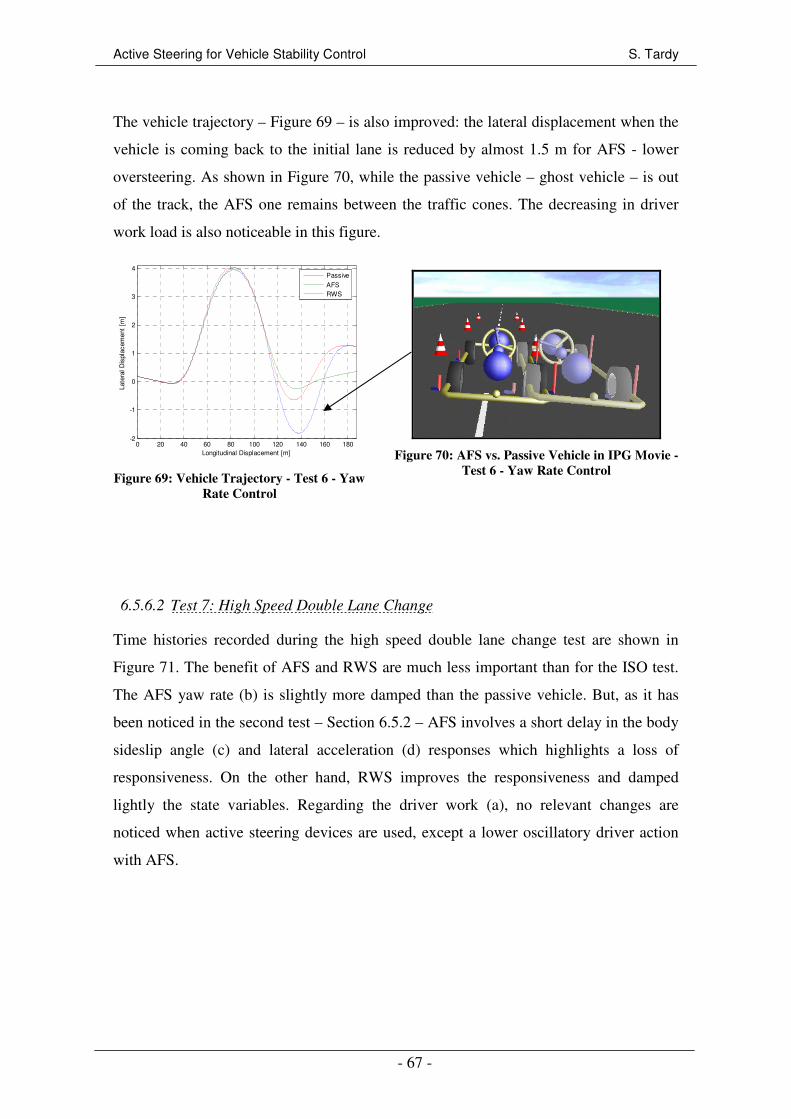
Active Steering for Vehicle Stability Control S. Tardy
- 67 -
The vehicle trajectory – Figure 69 – is also improved: the lateral displacement when the
vehicle is coming back to the initial lane is reduced by almost 1.5 m for AFS - lower
oversteering. As shown in Figure 70, while the passive vehicle – ghost vehicle – is out
of the track, the AFS one remains between the traffic cones. The decreasing in driver
work load is also noticeable in this figure.
0 20 40 60 80 100 120 140 160 180-2
-1
0
1
2
3
4
Longitudinal Displacement [m]
Late
ral D
ispl
acem
ent
[m]
Passive
AFSRWS
Figure 69: Vehicle Trajectory - Test 6 - Yaw
Rate Control
Figure 70: AFS vs. Passive Vehicle in IPG Movie -
Test 6 - Yaw Rate Control
6.5.6.2 Test 7: High Speed Double Lane Change
Time histories recorded during the high speed double lane change test are shown in
Figure 71. The benefit of AFS and RWS are much less important than for the ISO test.
The AFS yaw rate (b) is slightly more damped than the passive vehicle. But, as it has
been noticed in the second test – Section 6.5.2 – AFS involves a short delay in the body
sideslip angle (c) and lateral acceleration (d) responses which highlights a loss of
responsiveness. On the other hand, RWS improves the responsiveness and damped
lightly the state variables. Regarding the driver work (a), no relevant changes are
noticed when active steering devices are used, except a lower oscillatory driver action
with AFS.

Active Steering for Vehicle Stability Control S. Tardy
- 68 -
0 0.5 1 1.5 2 2.5 3 3.5 4 4.5 5-50
-40
-30
-20
-10
0
10
20
30
Time [s]
Ste
erin
g W
heel
Ang
le [
deg]
Passive
AFS
RWS
0 0.5 1 1.5 2 2.5 3 3.5 4 4.5 5
-0.2
-0.1
0
0.1
0.2
0.3
Time [s]
Yaw
Rat
e [r
ad/s
]
Passive
AFS
RWSReference Yaw Rate AFS
Reference Yaw Rate RWS
0 0.5 1 1.5 2 2.5 3 3.5 4 4.5 5
-0.04
-0.02
0
0.02
0.04
0.06
Time [s]
Veh
icle
Bod
y S
ides
lip A
ngle
[ra
d]
Passive
AFS
RWS
0 0.5 1 1.5 2 2.5 3 3.5 4 4.5 5-8
-6
-4
-2
0
2
4
6
Time [s]
Late
ral A
ccel
erat
ion
[m/s
2 ]
Passive
AFS
RWS
0 0.5 1 1.5 2 2.5 3 3.5 4 4.5 5
-0.015
-0.01
-0.005
0
0.005
0.01
0.015
Time [s]
Act
ive
Ste
er A
ngle
[ra
d]
AFS
RWS
0 20 40 60 80 100 120 140 160 180 200-0.5
0
0.5
1
1.5
2
2.5
3
3.5
Longitudinal Displacement [m]
Late
ral D
ispl
acem
ent
[m]
Passive
AFSRWS
Figure 71: Time Histories - Test 7 - Yaw Rate Control
Considering the body sideslip phase plane shown in Figure 72, it can be noticed that
both AFS and RWS enhance slightly the stability as their curves are surrounded by the
passive vehicle curve.
(a) (b)
(e) (f)
(c) (d)
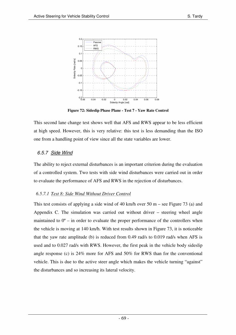
Active Steering for Vehicle Stability Control S. Tardy
- 69 -
-0.06 -0.04 -0.02 0 0.02 0.04 0.06 0.08-0.2
-0.15
-0.1
-0.05
0
0.05
0.1
0.15
0.2
Sideslip Angle [rad]
Sid
eslip
Rat
e [r
ad/s
]
Passive
AFSRWS
Figure 72: Sideslip Phase Plane - Test 7 - Yaw Rate Control
This second lane change test shows well that AFS and RWS appear to be less efficient
at high speed. However, this is very relative: this test is less demanding than the ISO
one from a handling point of view since all the state variables are lower.
6.5.7 Side Wind
The ability to reject external disturbances is an important criterion during the evaluation
of a controlled system. Two tests with side wind disturbances were carried out in order
to evaluate the performance of AFS and RWS in the rejection of disturbances.
6.5.7.1 Test 8: Side Wind Without Driver Control
This test consists of applying a side wind of 40 km/h over 50 m – see Figure 73 (a) and
Appendix C. The simulation was carried out without driver – steering wheel angle
maintained to 0º – in order to evaluate the proper performance of the controllers when
the vehicle is moving at 140 km/h. With test results shown in Figure 73, it is noticeable
that the yaw rate amplitude (b) is reduced from 0.49 rad/s to 0.019 rad/s when AFS is
used and to 0.027 rad/s with RWS. However, the first peak in the vehicle body sideslip
angle response (c) is 24% more for AFS and 50% for RWS than for the conventional
vehicle. This is due to the active steer angle which makes the vehicle turning “against”
the disturbances and so increasing its lateral velocity.
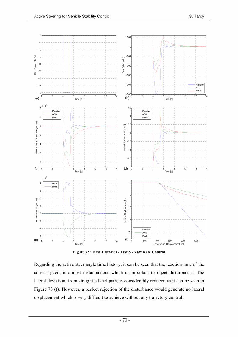
Active Steering for Vehicle Stability Control S. Tardy
- 70 -
0 2 4 6 8 10 12 14
-40
-35
-30
-25
-20
-15
-10
-5
0
Time [s]
Win
d S
peed
[K
m/h
]
0 2 4 6 8 10 12 14-0.05
-0.04
-0.03
-0.02
-0.01
0
0.01
Time [s]
Yaw
Rat
e [r
ad/s
]
Passive
AFS
RWS
0 2 4 6 8 10 12 14
-8
-6
-4
-2
0
2
4x 10
-3
Time [s]
Veh
icle
Bod
y S
ides
lip A
ngle
[ra
d]
Passive
AFSRWS
0 2 4 6 8 10 12 14-2
-1.5
-1
-0.5
0
0.5
1
1.5
Time [s]
Late
ral A
ccel
erat
ion
[m/s
2 ]
Passive
AFSRWS
0 2 4 6 8 10 12 14
-3
-2
-1
0
1
2
3
4
x 10-3
Time [s]
Act
ive
Ste
er A
ngle
[ra
d]
AFS
RWS
0 100 200 300 400 500
-20
-15
-10
-5
0
Longitudinal Displacement [m]
Late
ral D
ispl
acem
ent
[m]
Passive
AFS
RWS
Figure 73: Time Histories - Test 8 - Yaw Rate Control
Regarding the active steer angle time history, it can be seen that the reaction time of the
active system is almost instantaneous which is important to reject disturbances. The
lateral deviation, from straight a head path, is considerably reduced as it can be seen in
Figure 73 (f). However, a perfect rejection of the disturbance would generate no lateral
displacement which is very difficult to achieve without any trajectory control.
(a) (b)
(c) (d)
(e) (f)
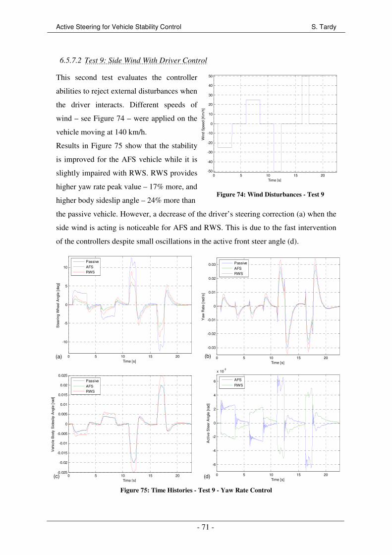
Active Steering for Vehicle Stability Control S. Tardy
- 71 -
6.5.7.2 Test 9: Side Wind With Driver Control
This second test evaluates the controller
abilities to reject external disturbances when
the driver interacts. Different speeds of
wind – see Figure 74 – were applied on the
vehicle moving at 140 km/h.
Results in Figure 75 show that the stability
is improved for the AFS vehicle while it is
slightly impaired with RWS. RWS provides
higher yaw rate peak value – 17% more, and
higher body sideslip angle – 24% more than
0 5 10 15 20-50
-40
-30
-20
-10
0
10
20
30
40
50
Time [s]
Win
d S
peed
[K
m/h
]
Figure 74: Wind Disturbances - Test 9
the passive vehicle. However, a decrease of the driver’s steering correction (a) when the
side wind is acting is noticeable for AFS and RWS. This is due to the fast intervention
of the controllers despite small oscillations in the active front steer angle (d).
0 5 10 15 20
-10
-5
0
5
10
Time [s]
Ste
erin
g W
heel
Ang
le [
deg]
Passive
AFSRWS
0 5 10 15 20
-0.03
-0.02
-0.01
0
0.01
0.02
0.03
Time [s]
Yaw
Rat
e [r
ad/s
]
Passive
AFSRWS
0 5 10 15 20-0.025
-0.02
-0.015
-0.01
-0.005
0
0.005
0.01
0.015
0.02
0.025
Time [s]
Veh
icle
Bod
y S
ides
lip A
ngle
[ra
d]
Passive
AFSRWS
0 5 10 15 20
-6
-4
-2
0
2
4
6
x 10-3
Time [s]
Act
ive
Ste
er A
ngle
[ra
d]
AFS
RWS
Figure 75: Time Histories - Test 9 - Yaw Rate Control
(d)
(a) (b)
(c)
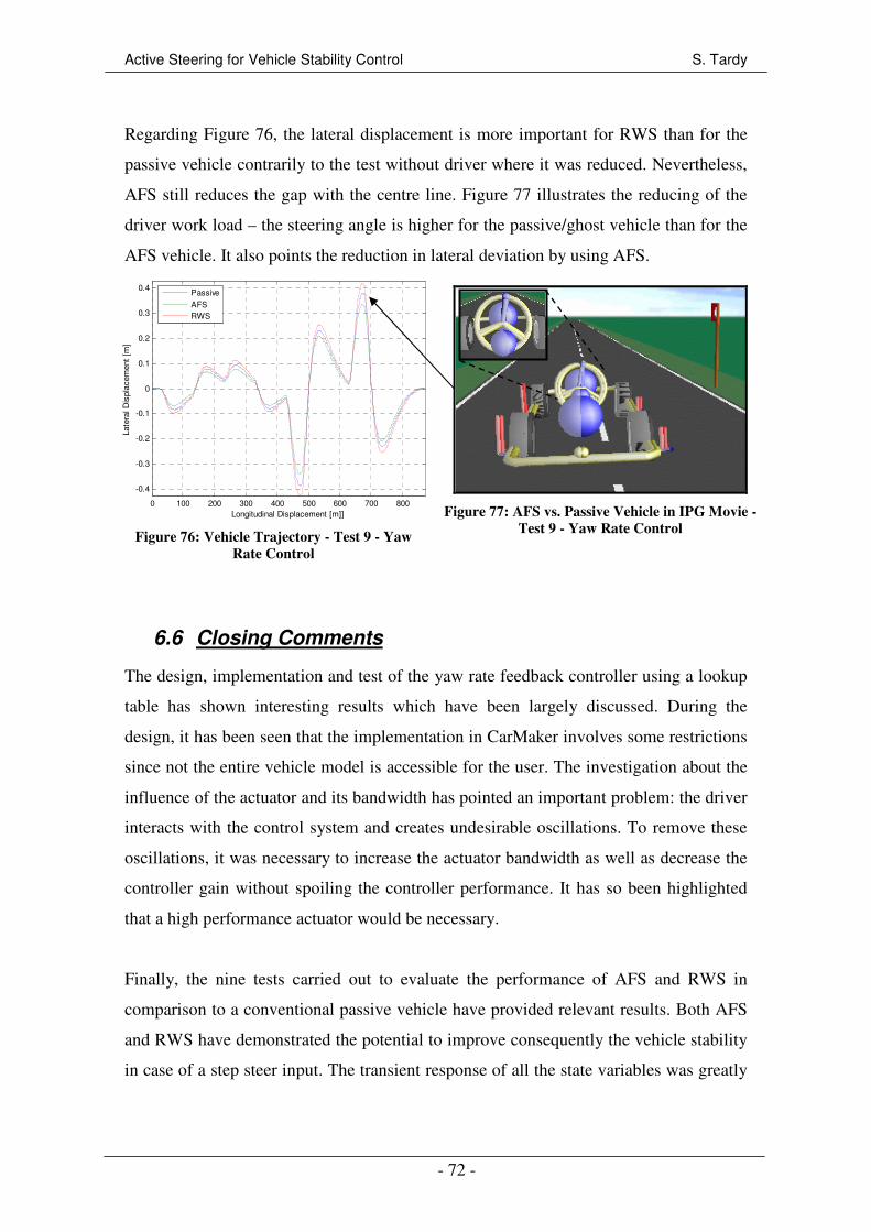
Active Steering for Vehicle Stability Control S. Tardy
- 72 -
Regarding Figure 76, the lateral displacement is more important for RWS than for the
passive vehicle contrarily to the test without driver where it was reduced. Nevertheless,
AFS still reduces the gap with the centre line. Figure 77 illustrates the reducing of the
driver work load – the steering angle is higher for the passive/ghost vehicle than for the
AFS vehicle. It also points the reduction in lateral deviation by using AFS.
0 100 200 300 400 500 600 700 800
-0.4
-0.3
-0.2
-0.1
0
0.1
0.2
0.3
0.4
Longitudinal Displacement [m]]
Late
ral D
ispl
acem
ent
[m]
Passive
AFSRWS
Figure 76: Vehicle Trajectory - Test 9 - Yaw
Rate Control
Figure 77: AFS vs. Passive Vehicle in IPG Movie -
Test 9 - Yaw Rate Control
6.6 Closing Comments
The design, implementation and test of the yaw rate feedback controller using a lookup
table has shown interesting results which have been largely discussed. During the
design, it has been seen that the implementation in CarMaker involves some restrictions
since not the entire vehicle model is accessible for the user. The investigation about the
influence of the actuator and its bandwidth has pointed an important problem: the driver
interacts with the control system and creates undesirable oscillations. To remove these
oscillations, it was necessary to increase the actuator bandwidth as well as decrease the
controller gain without spoiling the controller performance. It has so been highlighted
that a high performance actuator would be necessary.
Finally, the nine tests carried out to evaluate the performance of AFS and RWS in
comparison to a conventional passive vehicle have provided relevant results. Both AFS
and RWS have demonstrated the potential to improve consequently the vehicle stability
in case of a step steer input. The transient response of all the state variables was greatly
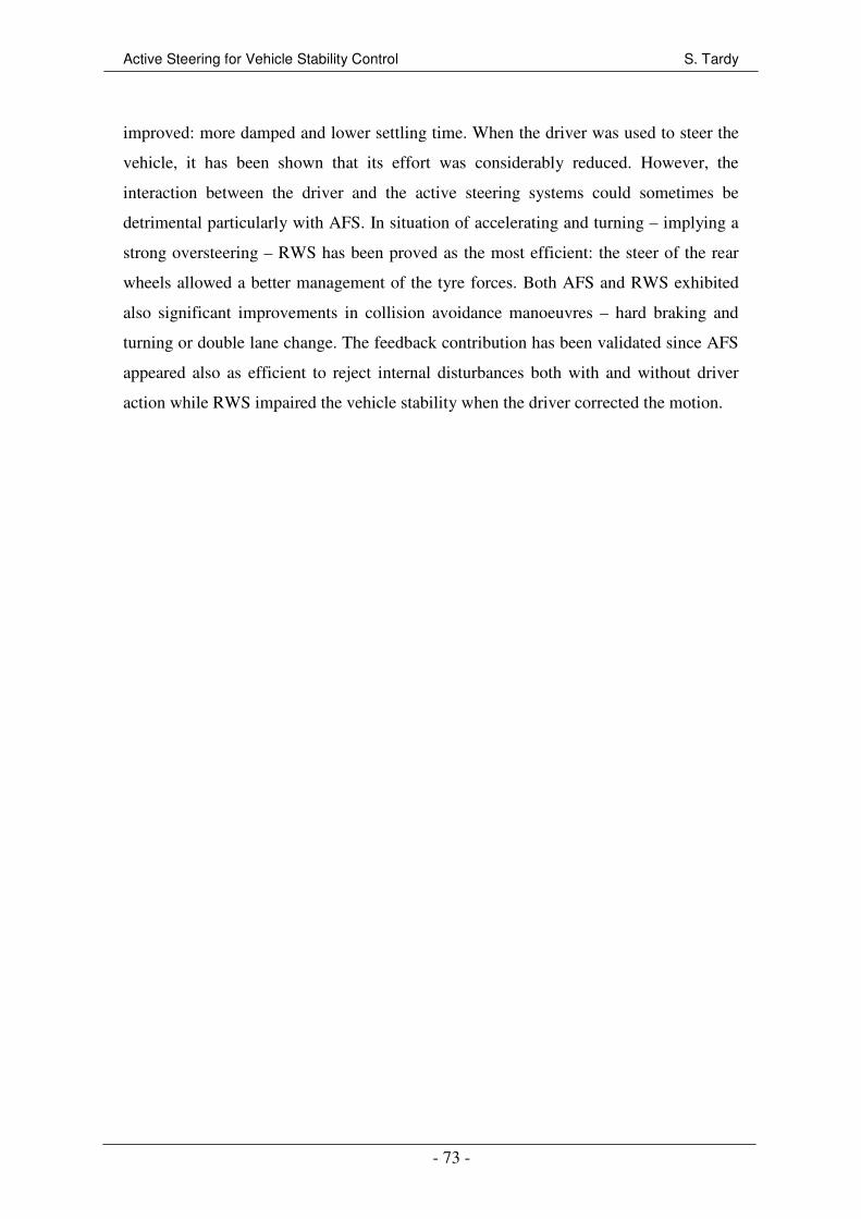
Active Steering for Vehicle Stability Control S. Tardy
- 73 -
improved: more damped and lower settling time. When the driver was used to steer the
vehicle, it has been shown that its effort was considerably reduced. However, the
interaction between the driver and the active steering systems could sometimes be
detrimental particularly with AFS. In situation of accelerating and turning – implying a
strong oversteering – RWS has been proved as the most efficient: the steer of the rear
wheels allowed a better management of the tyre forces. Both AFS and RWS exhibited
also significant improvements in collision avoidance manoeuvres – hard braking and
turning or double lane change. The feedback contribution has been validated since AFS
appeared also as efficient to reject internal disturbances both with and without driver
action while RWS impaired the vehicle stability when the driver corrected the motion.
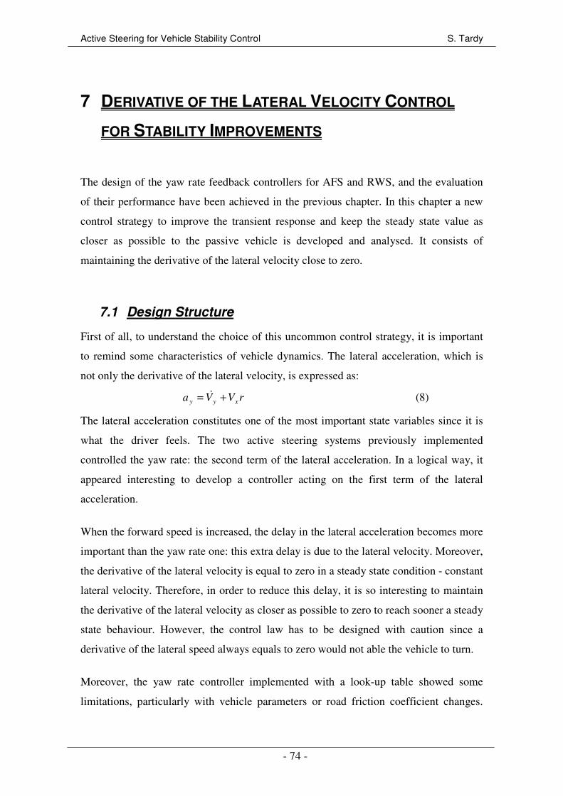
Active Steering for Vehicle Stability Control S. Tardy
- 74 -
7 DERIVATIVE OF THE LATERAL VELOCITY CONTROL
FOR STABILITY IMPROVEMENTS
The design of the yaw rate feedback controllers for AFS and RWS, and the evaluation
of their performance have been achieved in the previous chapter. In this chapter a new
control strategy to improve the transient response and keep the steady state value as
closer as possible to the passive vehicle is developed and analysed. It consists of
maintaining the derivative of the lateral velocity close to zero.
7.1 Design Structure
First of all, to understand the choice of this uncommon control strategy, it is important
to remind some characteristics of vehicle dynamics. The lateral acceleration, which is
not only the derivative of the lateral velocity, is expressed as:
rVVa xyy += & (8)
The lateral acceleration constitutes one of the most important state variables since it is
what the driver feels. The two active steering systems previously implemented
controlled the yaw rate: the second term of the lateral acceleration. In a logical way, it
appeared interesting to develop a controller acting on the first term of the lateral
acceleration.
When the forward speed is increased, the delay in the lateral acceleration becomes more
important than the yaw rate one: this extra delay is due to the lateral velocity. Moreover,
the derivative of the lateral velocity is equal to zero in a steady state condition - constant
lateral velocity. Therefore, in order to reduce this delay, it is so interesting to maintain
the derivative of the lateral velocity as closer as possible to zero to reach sooner a steady
state behaviour. However, the control law has to be designed with caution since a
derivative of the lateral speed always equals to zero would not able the vehicle to turn.
Moreover, the yaw rate controller implemented with a look-up table showed some
limitations, particularly with vehicle parameters or road friction coefficient changes.
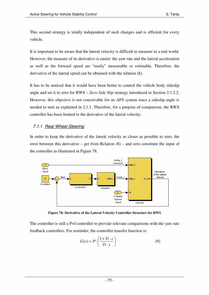
Active Steering for Vehicle Stability Control S. Tardy
- 75 -
This second strategy is totally independent of such changes and is efficient for every
vehicle.
It is important to be aware that the lateral velocity is difficult to measure in a real world.
However, the measure of its derivative is easier: the yaw rate and the lateral acceleration
as well as the forward speed are “easily” measurable or estimable. Therefore, the
derivative of the lateral speed can be obtained with the relation (8).
It has to be noticed that it would have been better to control the vehicle body sideslip
angle and set it to zero for RWS – Zero Side Slip strategy introduced in Section 2.1.2.2.
However, this objective is not conceivable for an AFS system since a sideslip angle is
needed to turn as explained in 2.1.1. Therefore, for a purpose of comparison, the RWS
controller has been limited to the derivative of the lateral velocity.
7.1.1 Rear Wheel Steering
In order to keep the derivative of the lateral velocity as closer as possible to zero, the
error between this derivative – get from Relation (8) – and zero constitute the input of
the controller as illustrated in Figure 78.
Figure 78: Derivative of the Lateral Velocity Controller Structure for RWS
The controller is still a P+I controller to provide relevant comparisons with the yaw rate
feedback controllers. For reminder, the controller transfer function is:
⋅
⋅+⋅=
sTi
sTiPsG
1)( (9)

Active Steering for Vehicle Stability Control S. Tardy
- 76 -
7.1.2 Active Front Steering
For AFS, the layout shown in Figure 79 is very similar to the RWS one. But, instead of
steering the rear wheels, the active component is added to the steer angle created by the
driver and used to steer the front wheels.
Figure 79: Derivative of the Lateral Velocity Controller Structure for AFS
7.2 System Adaptation for CarMaker
The method used to implement the yV& controller in CarMaker is similar to the one
presented in Section 6.2.1 for the RWS yaw rate controller. The actuation of the wheels
is still done by overwriting the orientation angle of the wheels. Thus, only the controller
block is presented here, it can be referred to Section 6.2.1 for a detailed explanation of
the system integration in the vehicle model.
Figure 80: CarMaker Derivative of the Lateral Velocity Controller Layout for RWS
As shown in Figure 80 for RWS, the lateral acceleration Car.ay, the yaw rate
Car.YawRate and the forward velocity Car.vx are read from the CarMaker dictionary
and used to calculate – Relation (8) – the derivative of the lateral velocity which is

Active Steering for Vehicle Stability Control S. Tardy
- 77 -
compared with a constant sets to zero. The controller and actuator subsystems are the
same as for the yaw rate feedback controllers. The vehicle forward velocity Car.vx is
also used to provide a switch-off of the active device when the speed is less than 15 m/s.
The driver steer angle Delta_f is only calculated for presentation of the results; it does
not have any influence or interaction with the controller.
7.3 Integration of the Actuator
With the aim to compare this new control strategy with the yaw rate feedback
controller, the actuator model has to be the same. Therefore, the bandwidth of the
actuator is set to 13 Hz. Note that the interaction actuator/driver involved also
oscillations for this control strategy for low bandwidth.
7.4 Controller Tuning
The two controllers have been tuned by following the same method introduced in
Section 6.3. A summarization of the parameters is given in Table 4 – actuator
integrated.
Table 4: P+I Controllers’ Parameters - Derivative of the Lateral Velocity Control
AFS RWS
Proportional gain – P 0.1 0.06
Integral Time Constant – Ti 10 10
7.5 Performance Analysis
All the tests performed in this section aim to evaluate the performance of this second
controller. Theses tests are the same as those used for the yaw rate feedback controller
analysis. Therefore, the test boundaries are not discussed again. For each test, AFS and
RWS vehicles responses are compared with the passive FWS vehicle.
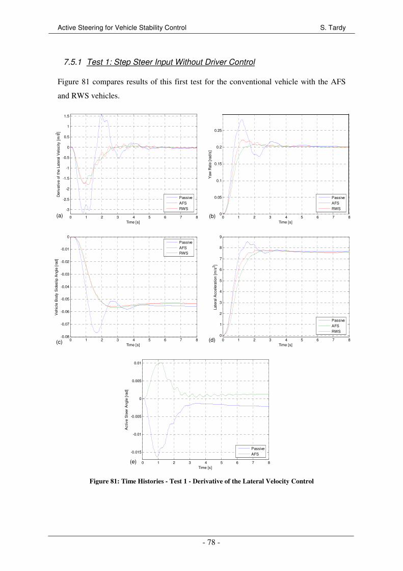
Active Steering for Vehicle Stability Control S. Tardy
- 78 -
7.5.1 Test 1: Step Steer Input Without Driver Control
Figure 81 compares results of this first test for the conventional vehicle with the AFS
and RWS vehicles.
0 1 2 3 4 5 6 7 8
-3
-2.5
-2
-1.5
-1
-0.5
0
0.5
1
1.5
Time [s]
Der
ivat
ive
of t
he L
ater
al V
eloc
ity [
m/s2 ]
Passive
AFS
RWS
0 1 2 3 4 5 6 7 80
0.05
0.1
0.15
0.2
0.25
Time [s]
Yaw
Rat
e [r
ad/s
]
Passive
AFS
RWS
0 1 2 3 4 5 6 7 8-0.08
-0.07
-0.06
-0.05
-0.04
-0.03
-0.02
-0.01
0
Time [s]
Veh
icle
Bod
y S
ides
lip A
ngle
[ra
d]
Passive
AFSRWS
0 1 2 3 4 5 6 7 80
1
2
3
4
5
6
7
8
9
Time [s]
Late
ral A
ccel
erat
ion
[m/s
2 ]
Passive
AFS
RWS
0 1 2 3 4 5 6 7 8
-0.015
-0.01
-0.005
0
0.005
0.01
Time [s]
Act
ive
Ste
er A
ngle
[ra
d]
Passive
AFS
Figure 81: Time Histories - Test 1 - Derivative of the Lateral Velocity Control
(a) (b)
(c) (d)
(e)
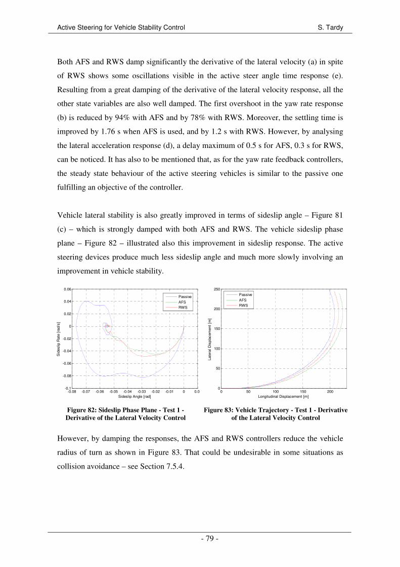
Active Steering for Vehicle Stability Control S. Tardy
- 79 -
Both AFS and RWS damp significantly the derivative of the lateral velocity (a) in spite
of RWS shows some oscillations visible in the active steer angle time response (e).
Resulting from a great damping of the derivative of the lateral velocity response, all the
other state variables are also well damped. The first overshoot in the yaw rate response
(b) is reduced by 94% with AFS and by 78% with RWS. Moreover, the settling time is
improved by 1.76 s when AFS is used, and by 1.2 s with RWS. However, by analysing
the lateral acceleration response (d), a delay maximum of 0.5 s for AFS, 0.3 s for RWS,
can be noticed. It has also to be mentioned that, as for the yaw rate feedback controllers,
the steady state behaviour of the active steering vehicles is similar to the passive one
fulfilling an objective of the controller.
Vehicle lateral stability is also greatly improved in terms of sideslip angle – Figure 81
(c) – which is strongly damped with both AFS and RWS. The vehicle sideslip phase
plane – Figure 82 – illustrated also this improvement in sideslip response. The active
steering devices produce much less sideslip angle and much more slowly involving an
improvement in vehicle stability.
-0.08 -0.07 -0.06 -0.05 -0.04 -0.03 -0.02 -0.01 0 0.01-0.1
-0.08
-0.06
-0.04
-0.02
0
0.02
0.04
0.06
Sideslip Angle [rad]
Sid
eslip
Rat
e [r
ad/s
]
Passive
AFSRWS
Figure 82: Sideslip Phase Plane - Test 1 -
Derivative of the Lateral Velocity Control
0 50 100 150 2000
50
100
150
200
250
Longitudinal Displacement [m]
Late
ral D
ispl
acem
ent
[m]
Passive
AFSRWS
Figure 83: Vehicle Trajectory - Test 1 - Derivative
of the Lateral Velocity Control
However, by damping the responses, the AFS and RWS controllers reduce the vehicle
radius of turn as shown in Figure 83. That could be undesirable in some situations as
collision avoidance – see Section 7.5.4.
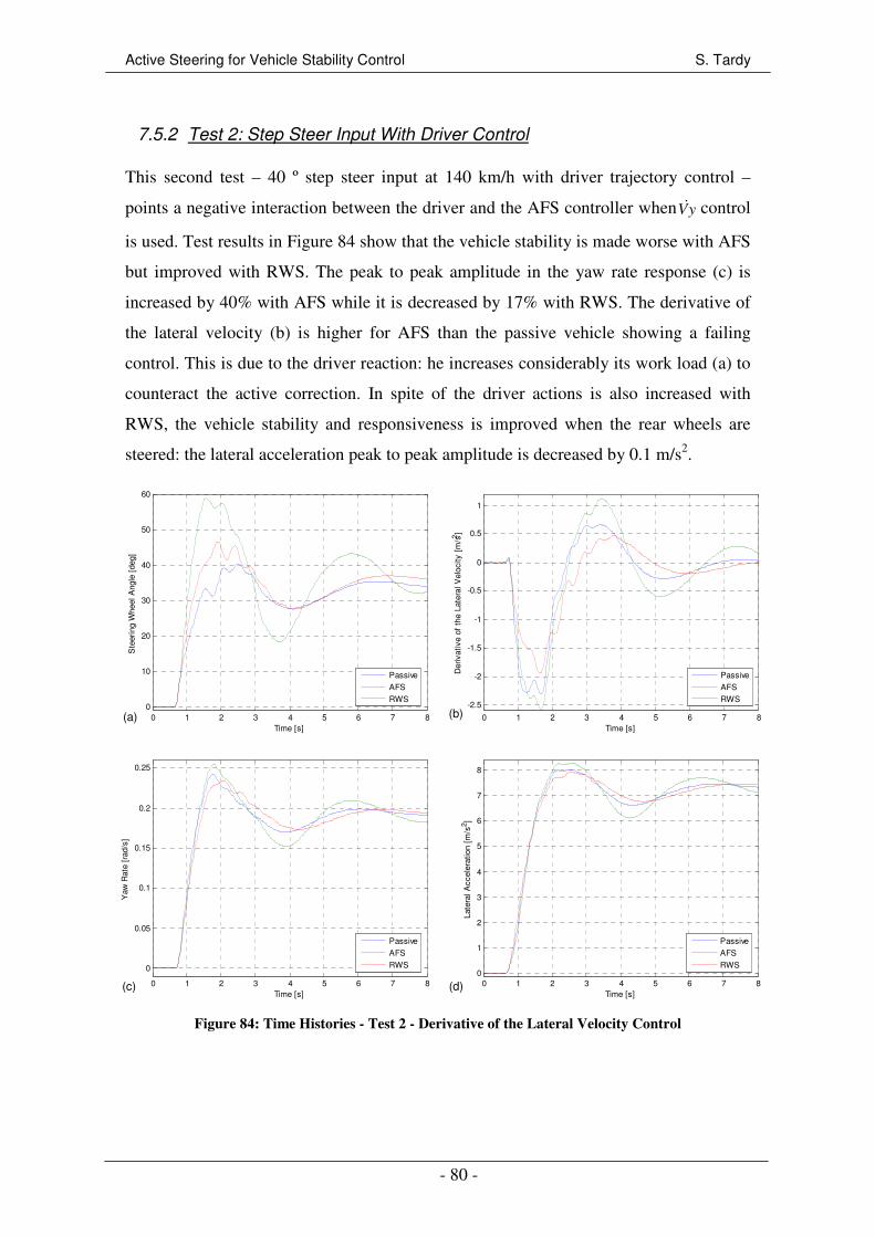
Active Steering for Vehicle Stability Control S. Tardy
- 80 -
7.5.2 Test 2: Step Steer Input With Driver Control
This second test – 40 º step steer input at 140 km/h with driver trajectory control –
points a negative interaction between the driver and the AFS controller when yV& control
is used. Test results in Figure 84 show that the vehicle stability is made worse with AFS
but improved with RWS. The peak to peak amplitude in the yaw rate response (c) is
increased by 40% with AFS while it is decreased by 17% with RWS. The derivative of
the lateral velocity (b) is higher for AFS than the passive vehicle showing a failing
control. This is due to the driver reaction: he increases considerably its work load (a) to
counteract the active correction. In spite of the driver actions is also increased with
RWS, the vehicle stability and responsiveness is improved when the rear wheels are
steered: the lateral acceleration peak to peak amplitude is decreased by 0.1 m/s2.
0 1 2 3 4 5 6 7 80
10
20
30
40
50
60
Time [s]
Ste
erin
g W
heel
Ang
le [
deg]
Passive
AFS
RWS
0 1 2 3 4 5 6 7 8
-2.5
-2
-1.5
-1
-0.5
0
0.5
1
Time [s]
Der
ivat
ive
of t
he L
ater
al V
eloc
ity [
m/s2 ]
Passive
AFS
RWS
0 1 2 3 4 5 6 7 8
0
0.05
0.1
0.15
0.2
0.25
Time [s]
Yaw
Rat
e [r
ad/s
]
Passive
AFS
RWS
0 1 2 3 4 5 6 7 80
1
2
3
4
5
6
7
8
Time [s]
Late
ral A
ccel
erat
ion
[m/s
2 ]
Passive
AFS
RWS
Figure 84: Time Histories - Test 2 - Derivative of the Lateral Velocity Control
(c)
(a) (b)
(d)
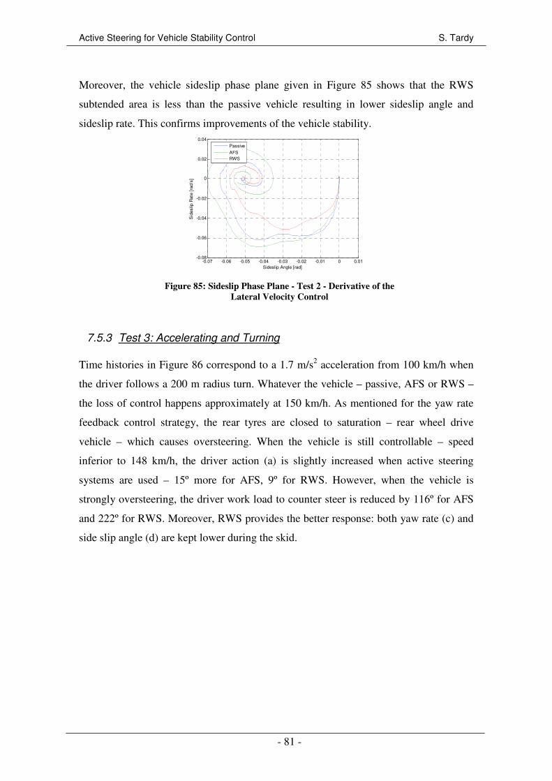
Active Steering for Vehicle Stability Control S. Tardy
- 81 -
Moreover, the vehicle sideslip phase plane given in Figure 85 shows that the RWS
subtended area is less than the passive vehicle resulting in lower sideslip angle and
sideslip rate. This confirms improvements of the vehicle stability.
-0.07 -0.06 -0.05 -0.04 -0.03 -0.02 -0.01 0 0.01-0.08
-0.06
-0.04
-0.02
0
0.02
0.04
Sideslip Angle [rad]
Sid
eslip
Rat
e [r
ad/s
]
Passive
AFSRWS
Figure 85: Sideslip Phase Plane - Test 2 - Derivative of the
Lateral Velocity Control
7.5.3 Test 3: Accelerating and Turning
Time histories in Figure 86 correspond to a 1.7 m/s2 acceleration from 100 km/h when
the driver follows a 200 m radius turn. Whatever the vehicle – passive, AFS or RWS –
the loss of control happens approximately at 150 km/h. As mentioned for the yaw rate
feedback control strategy, the rear tyres are closed to saturation – rear wheel drive
vehicle – which causes oversteering. When the vehicle is still controllable – speed
inferior to 148 km/h, the driver action (a) is slightly increased when active steering
systems are used – 15º more for AFS, 9º for RWS. However, when the vehicle is
strongly oversteering, the driver work load to counter steer is reduced by 116º for AFS
and 222º for RWS. Moreover, RWS provides the better response: both yaw rate (c) and
side slip angle (d) are kept lower during the skid.
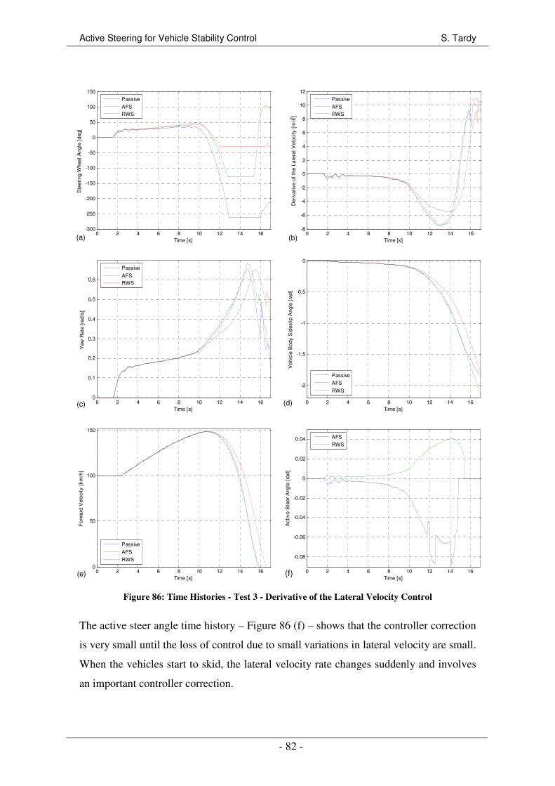
Active Steering for Vehicle Stability Control S. Tardy
- 82 -
0 2 4 6 8 10 12 14 16-300
-250
-200
-150
-100
-50
0
50
100
150
Time [s]
Ste
erin
g W
heel
Ang
le [
deg]
Passive
AFSRWS
0 2 4 6 8 10 12 14 16-8
-6
-4
-2
0
2
4
6
8
10
12
Time [s]
Der
ivat
ive
of t
he L
ater
al V
eloc
ity [
m/s2 ]
Passive
AFSRWS
0 2 4 6 8 10 12 14 160
0.1
0.2
0.3
0.4
0.5
0.6
Time [s]
Yaw
Rat
e [r
ad/s
]
Passive
AFSRWS
0 2 4 6 8 10 12 14 16
-2
-1.5
-1
-0.5
0
Time [s]
Veh
icle
Bod
y S
ides
lip A
ngle
[ra
d]
Passive
AFS
RWS
0 2 4 6 8 10 12 14 160
50
100
150
Time [s]
For
war
d V
eloc
ity [
km/h
]
Passive
AFS
RWS
0 2 4 6 8 10 12 14 16
-0.08
-0.06
-0.04
-0.02
0
0.02
0.04
Time [s]
Act
ive
Ste
er A
ngle
[ra
d]
AFS
RWS
Figure 86: Time Histories - Test 3 - Derivative of the Lateral Velocity Control
The active steer angle time history – Figure 86 (f) – shows that the controller correction
is very small until the loss of control due to small variations in lateral velocity are small.
When the vehicles start to skid, the lateral velocity rate changes suddenly and involves
an important controller correction.
(a) (b)
(c) (d)
(e) (f)

Active Steering for Vehicle Stability Control S. Tardy
- 83 -
7.5.4 Test 4: Braking and Turning
As a quick remind, this test is a combination of a step steer input of 50º and a hard
braking generating a 1.01g deceleration. Yaw rate (a), body sideslip angle (b) and lateral
acceleration (c) time histories as well as the vehicle trajectories are represented in
Figure 87. It can be noticed that the state variables are reduced by the active systems
resulting in a lower lateral displacement (d). This is due to the structure of the
controller: it aims to minimize sudden lateral velocity variations and so damp sudden
variations in all state variables. The lateral displacement of the AFS vehicle is 1.37 m
whereas it is 2.14 m for the passive vehicle and 2.02 m for RWS.
0 1 2 3 4 5 6 7 8
0
0.02
0.04
0.06
0.08
0.1
0.12
0.14
0.16
Time [s]
Yaw
Rat
e [r
ad/s
]
Passive
AFSRWS
0 1 2 3 4 5 6 7 8
-0.3
-0.25
-0.2
-0.15
-0.1
-0.05
0
Time [s]
Veh
icle
Bod
y S
ides
lip A
ngle
[ra
d]
Passive
AFS
RWS
0 1 2 3 4 5 6 7 8-1
-0.5
0
0.5
1
1.5
2
2.5
3
3.5
Time [s]
Late
ral A
ccel
erat
ion
[m/s
2 ]
Passive
AFS
RWS
0 20 40 60 80 100 120 140 1600
0.5
1
1.5
2
Longitudinal Displacement [m]
Late
ral D
ispl
acem
ent
[m]
Passive
AFSRWS
Figure 87: Time Histories - Test 4 - Derivative of the Lateral Velocity Control
The vehicle body sideslip phase plane – Figure 88 – demonstrates that the vehicle
stability is nevertheless improved for both AFS and RWS since the sideslip angle is
reduced by 37% for AFS and by 32% for RWS. The vehicle sideslip rate is also
reduced: 39% less for AFS and 33% for RWS.
(a) (b)
(c) (d)
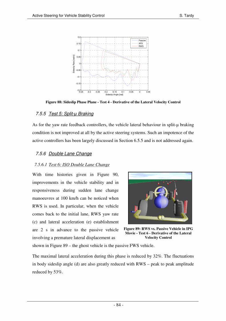
Active Steering for Vehicle Stability Control S. Tardy
- 84 -
-0.35 -0.3 -0.25 -0.2 -0.15 -0.1 -0.05 0 0.05-0.2
-0.15
-0.1
-0.05
0
0.05
0.1
0.15
0.2
Sideslip Angle [rad]
Sid
eslip
Rat
e [r
ad/s
]
Passive
AFSRWS
Figure 88: Sideslip Phase Plane - Test 4 - Derivative of the Lateral Velocity Control
7.5.5 Test 5: Split-µ Braking
As for the yaw rate feedback controllers, the vehicle lateral behaviour in split-µ braking
condition is not improved at all by the active steering systems. Such an impotence of the
active controllers has been largely discussed in Section 6.5.5 and is not addressed again.
7.5.6 Double Lane Change
7.5.6.1 Test 6: ISO Double Lane Change
With time histories given in Figure 90,
improvements in the vehicle stability and in
responsiveness during sudden lane change
manoeuvres at 100 km/h can be noticed when
RWS is used. In particular, when the vehicle
comes back to the initial lane, RWS yaw rate
(c) and lateral acceleration (e) establishment
are 2 s in advance to the passive vehicle
involving a premature lateral displacement as
Figure 89: RWS vs. Passive Vehicle in IPG
Movie - Test 6 - Derivative of the Lateral
Velocity Control
shown in Figure 89 – the ghost vehicle is the passive FWS vehicle.
The maximal lateral acceleration during this phase is reduced by 32%. The fluctuations
in body sideslip angle (d) are also greatly reduced with RWS – peak to peak amplitude
reduced by 53%.
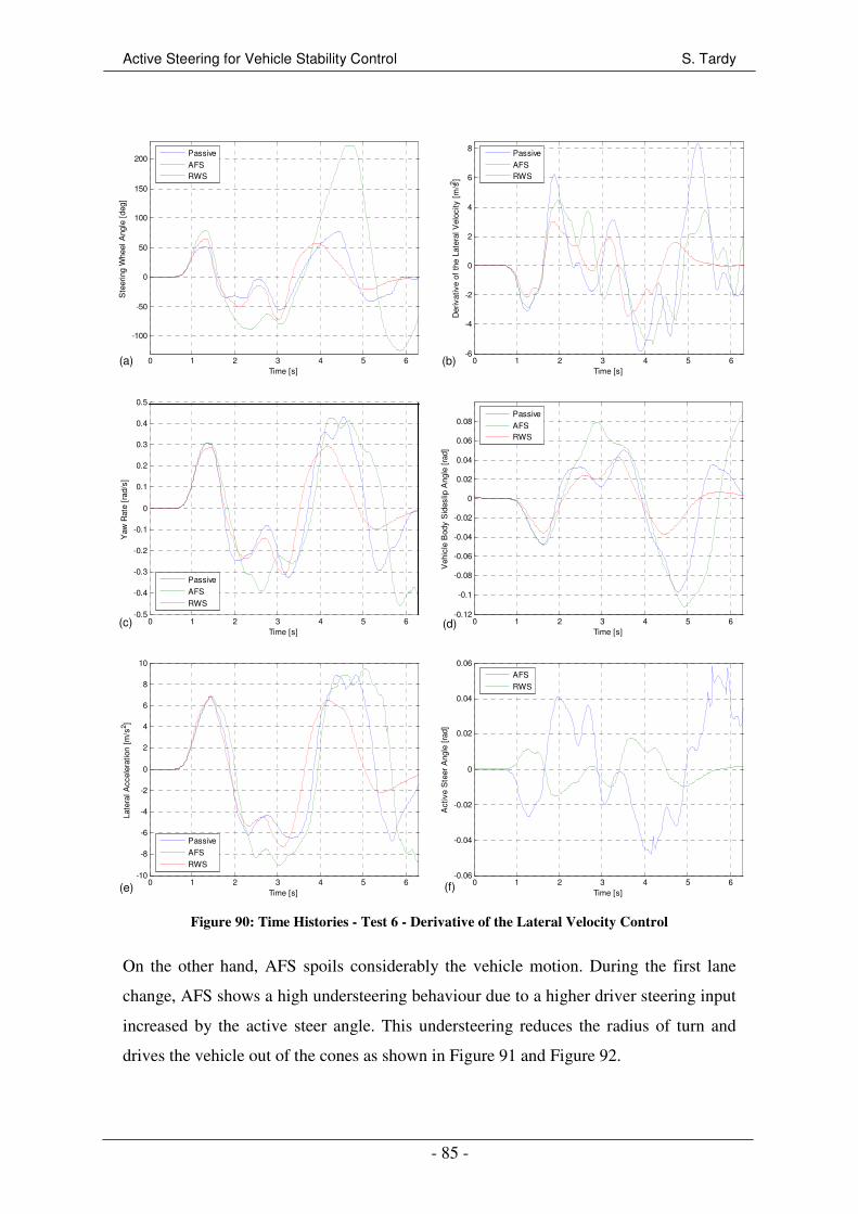
Active Steering for Vehicle Stability Control S. Tardy
- 85 -
0 1 2 3 4 5 6
-100
-50
0
50
100
150
200
Time [s]
Ste
erin
g W
heel
Ang
le [
deg]
Passive
AFSRWS
0 1 2 3 4 5 6-6
-4
-2
0
2
4
6
8
Time [s]
Der
ivat
ive
of t
he L
ater
al V
eloc
ity [
m/s2 ]
Passive
AFSRWS
0 1 2 3 4 5 6-0.5
-0.4
-0.3
-0.2
-0.1
0
0.1
0.2
0.3
0.4
0.5
Time [s]
Yaw
Rat
e [r
ad/s
]
Passive
AFS
RWS
0 1 2 3 4 5 6-0.12
-0.1
-0.08
-0.06
-0.04
-0.02
0
0.02
0.04
0.06
0.08
Time [s]
Veh
icle
Bod
y S
ides
lip A
ngle
[ra
d]
Passive
AFSRWS
0 1 2 3 4 5 6-10
-8
-6
-4
-2
0
2
4
6
8
10
Time [s]
Late
ral A
ccel
erat
ion
[m/s
2 ]
Passive
AFS
RWS
0 1 2 3 4 5 6-0.06
-0.04
-0.02
0
0.02
0.04
0.06
Time [s]
Act
ive
Ste
er A
ngle
[ra
d]
AFS
RWS
Figure 90: Time Histories - Test 6 - Derivative of the Lateral Velocity Control
On the other hand, AFS spoils considerably the vehicle motion. During the first lane
change, AFS shows a high understeering behaviour due to a higher driver steering input
increased by the active steer angle. This understeering reduces the radius of turn and
drives the vehicle out of the cones as shown in Figure 91 and Figure 92.
(a) (b)
(c) (d)
(e) (f)
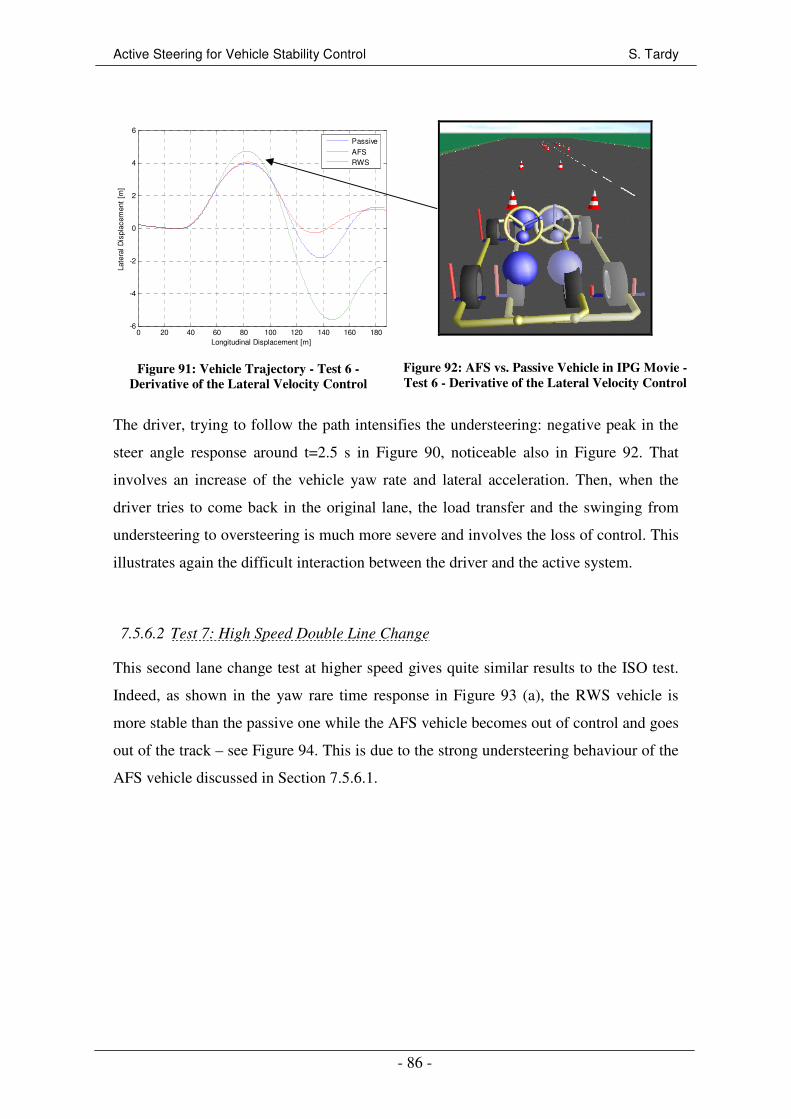
Active Steering for Vehicle Stability Control S. Tardy
- 86 -
0 20 40 60 80 100 120 140 160 180-6
-4
-2
0
2
4
6
Longitudinal Displacement [m]
Late
ral D
ispl
acem
ent
[m]
Passive
AFSRWS
Figure 91: Vehicle Trajectory - Test 6 -
Derivative of the Lateral Velocity Control
Figure 92: AFS vs. Passive Vehicle in IPG Movie -
Test 6 - Derivative of the Lateral Velocity Control
The driver, trying to follow the path intensifies the understeering: negative peak in the
steer angle response around t=2.5 s in Figure 90, noticeable also in Figure 92. That
involves an increase of the vehicle yaw rate and lateral acceleration. Then, when the
driver tries to come back in the original lane, the load transfer and the swinging from
understeering to oversteering is much more severe and involves the loss of control. This
illustrates again the difficult interaction between the driver and the active system.
7.5.6.2 Test 7: High Speed Double Line Change
This second lane change test at higher speed gives quite similar results to the ISO test.
Indeed, as shown in the yaw rare time response in Figure 93 (a), the RWS vehicle is
more stable than the passive one while the AFS vehicle becomes out of control and goes
out of the track – see Figure 94. This is due to the strong understeering behaviour of the
AFS vehicle discussed in Section 7.5.6.1.
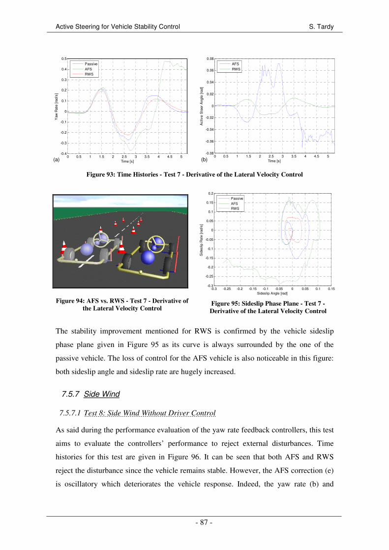
Active Steering for Vehicle Stability Control S. Tardy
- 87 -
0 0.5 1 1.5 2 2.5 3 3.5 4 4.5 5-0.4
-0.3
-0.2
-0.1
0
0.1
0.2
0.3
0.4
0.5
Time [s]
Yaw
Rat
e [r
ad/s
]
Passive
AFSRWS
0 0.5 1 1.5 2 2.5 3 3.5 4 4.5 5-0.08
-0.06
-0.04
-0.02
0
0.02
0.04
0.06
0.08
Time [s]
Act
ive
Ste
er A
ngle
[ra
d]
AFS
RWS
Figure 93: Time Histories - Test 7 - Derivative of the Lateral Velocity Control
Figure 94: AFS vs. RWS - Test 7 - Derivative of
the Lateral Velocity Control
-0.3 -0.25 -0.2 -0.15 -0.1 -0.05 0 0.05 0.1 0.15-0.3
-0.25
-0.2
-0.15
-0.1
-0.05
0
0.05
0.1
0.15
0.2
Sideslip Angle [rad]
Sid
eslip
Rat
e [r
ad/s
]Passive
AFSRWS
Figure 95: Sideslip Phase Plane - Test 7 -
Derivative of the Lateral Velocity Control
The stability improvement mentioned for RWS is confirmed by the vehicle sideslip
phase plane given in Figure 95 as its curve is always surrounded by the one of the
passive vehicle. The loss of control for the AFS vehicle is also noticeable in this figure:
both sideslip angle and sideslip rate are hugely increased.
7.5.7 Side Wind
7.5.7.1 Test 8: Side Wind Without Driver Control
As said during the performance evaluation of the yaw rate feedback controllers, this test
aims to evaluate the controllers’ performance to reject external disturbances. Time
histories for this test are given in Figure 96. It can be seen that both AFS and RWS
reject the disturbance since the vehicle remains stable. However, the AFS correction (e)
is oscillatory which deteriorates the vehicle response. Indeed, the yaw rate (b) and
(a) (b)

Active Steering for Vehicle Stability Control S. Tardy
- 88 -
lateral acceleration (d) peak values are much more important than for the passive
vehicle – yaw rate peak value multiplied by 7. Despite this distortion in yaw rate and
lateral acceleration, the vehicle body sideslip angle response (c) is well damped for AFS
since the peak to peak amplitude is reduced by 36%, thus improving the vehicle
stability.
0 2 4 6 8 10 12 14-2
-1.5
-1
-0.5
0
0.5
1
1.5
2
Time [s]
Der
ivat
ive
of t
he L
ater
al V
eloc
ity [
m/s2 ]
Passive
AFS
RWS
0 2 4 6 8 10 12 14
-0.06
-0.05
-0.04
-0.03
-0.02
-0.01
0
0.01
Time [s]
Yaw
Rat
e [r
ad/s
]
Passive
AFS
RWS
0 2 4 6 8 10 12 14
-4
-3
-2
-1
0
1
2
3
x 10-3
Time [s]
Veh
icle
Bod
y S
ides
lip A
ngle
[ra
d]
Passive
AFS
RWS
0 2 4 6 8 10 12 14
-3
-2.5
-2
-1.5
-1
-0.5
0
0.5
1
Time [s]
Late
ral A
ccel
erat
ion
[m/s
2 ]
Passive
AFS
RWS
0 2 4 6 8 10 12 14-0.02
-0.015
-0.01
-0.005
0
0.005
0.01
0.015
0.02
Time [s]
Act
ive
Ste
er A
ngle
[ra
d]
AFS
RWS
0 50 100 150 200 250 300 350-10
-9
-8
-7
-6
-5
-4
-3
-2
-1
0
Longitudinal Displacement [m]
Late
ral D
ispl
acem
ent
[m]
Passive
AFSRWS
Figure 96: Time Histories - Test 8 - Derivative of the Lateral Velocity Control
(a) (b)
(c) (d)
(e) (f)

Active Steering for Vehicle Stability Control S. Tardy
- 89 -
Concerning RWS, the stability is greatly enhanced since all the state variables are better
damped – no oscillation anymore. The overshoots in the yaw rate and lateral
acceleration responses are suppressed, and the peak to peak amplitude in body sideslip
angle is reduced by 44% in comparison with AFS and by 94% with the conventional
vehicle.
In spite of the vehicle stability is greatly improve with RWS and slightly with AFS, the
vehicle trajectory is not influenced by the active steering systems as shown in Figure 96
(f): the lateral deviation is changed by less than 10 cm.
7.5.7.2 Test 9: Side Wind With Driver Control
Results of this second side wind test – wind profile shows in Figure 97 (f) with driver
control – are shown in Figure 97. The two controllers reject the disturbance.
Nevertheless, all the state variables are increased. For example the yaw rate amplitude is
multiplied by 4.2, the vehicle body sideslip angle by 1.7 for AFS. That means the active
steering system impairs the vehicle stability when the driver controls the path,
highlighting one more time the detrimental interaction between the driver and the active
systems. In that results a growth of the necessary steering correction from the driver
when side wind is acting.
0 5 10 15 20-50
-40
-30
-20
-10
0
10
20
30
40
50
Time [s]
Win
d S
peed
[K
m/h
]
0 5 10 15 20-40
-30
-20
-10
0
10
20
30
40
Time [s]
Ste
erin
g W
heel
Ang
le [
deg]
Passive
AFSRWS
(a) (b)
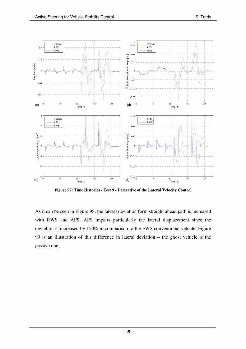
Active Steering for Vehicle Stability Control S. Tardy
- 90 -
0 5 10 15 20
-0.1
-0.05
0
0.05
0.1
Time [s]
Yaw
Rat
e [r
ad/s
]
Passive
AFSRWS
0 5 10 15 20
-0.03
-0.02
-0.01
0
0.01
0.02
0.03
Time [s]
Veh
icle
Bod
y S
ides
lip A
ngle
[ra
d]
Passive
AFSRWS
0 5 10 15 20-6
-4
-2
0
2
4
6
Time [s]
Late
ral A
ccel
erat
ion
[m/s
2 ]
Passive
AFSRWS
0 5 10 15 20-0.03
-0.02
-0.01
0
0.01
0.02
0.03
Time [s]
Act
ive
Ste
er A
ngle
[ra
d]
AFS
RWS
Figure 97: Time Histories - Test 9 - Derivative of the Lateral Velocity Control
As it can be seen in Figure 98, the lateral deviation form straight ahead path is increased
with RWS and AFS. AFS impairs particularly the lateral displacement since the
deviation is increased by 150% in comparison to the FWS conventional vehicle. Figure
99 is an illustration of this difference in lateral deviation – the ghost vehicle is the
passive one.
(c) (d)
(e) (f)
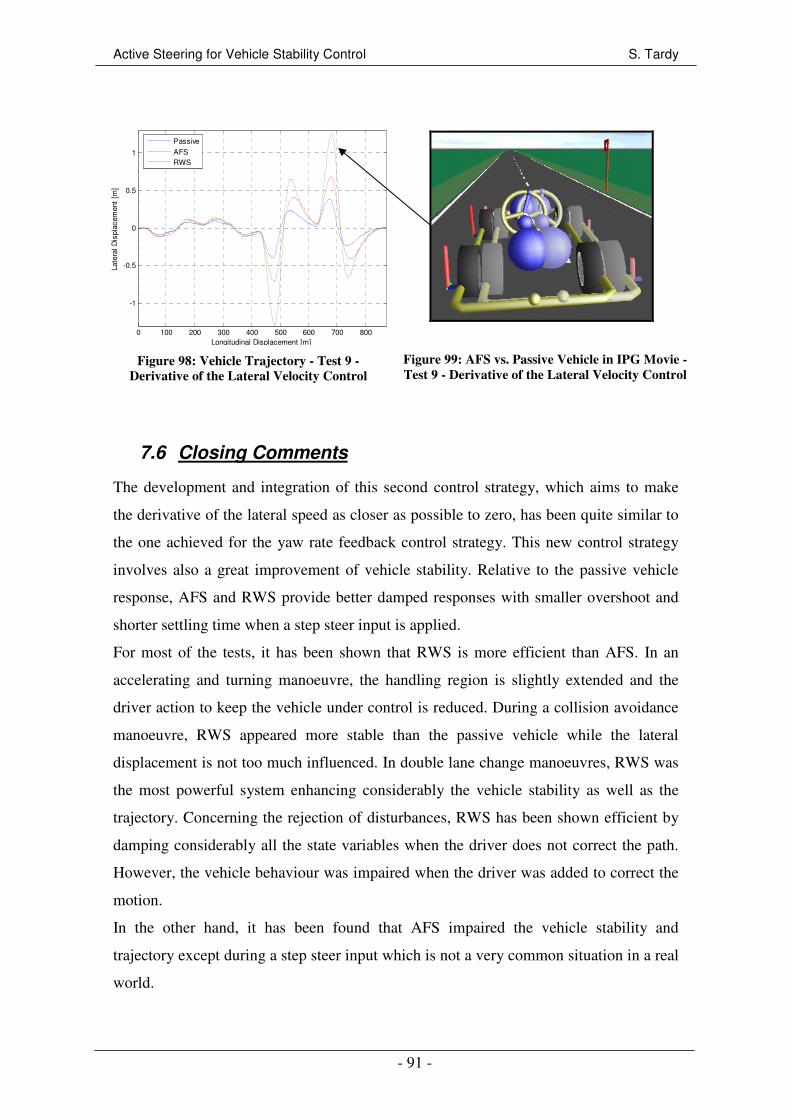
Active Steering for Vehicle Stability Control S. Tardy
- 91 -
0 100 200 300 400 500 600 700 800
-1
-0.5
0
0.5
1
Longitudinal Displacement [m]
Late
ral D
ispl
acem
ent
[m]
Passive
AFSRWS
Figure 98: Vehicle Trajectory - Test 9 -
Derivative of the Lateral Velocity Control
Figure 99: AFS vs. Passive Vehicle in IPG Movie -
Test 9 - Derivative of the Lateral Velocity Control
7.6 Closing Comments
The development and integration of this second control strategy, which aims to make
the derivative of the lateral speed as closer as possible to zero, has been quite similar to
the one achieved for the yaw rate feedback control strategy. This new control strategy
involves also a great improvement of vehicle stability. Relative to the passive vehicle
response, AFS and RWS provide better damped responses with smaller overshoot and
shorter settling time when a step steer input is applied.
For most of the tests, it has been shown that RWS is more efficient than AFS. In an
accelerating and turning manoeuvre, the handling region is slightly extended and the
driver action to keep the vehicle under control is reduced. During a collision avoidance
manoeuvre, RWS appeared more stable than the passive vehicle while the lateral
displacement is not too much influenced. In double lane change manoeuvres, RWS was
the most powerful system enhancing considerably the vehicle stability as well as the
trajectory. Concerning the rejection of disturbances, RWS has been shown efficient by
damping considerably all the state variables when the driver does not correct the path.
However, the vehicle behaviour was impaired when the driver was added to correct the
motion.
In the other hand, it has been found that AFS impaired the vehicle stability and
trajectory except during a step steer input which is not a very common situation in a real
world.
Active Steering for Vehicle Stability Control S. Tardy
- 92 -
8 COMPARISON OF THE TWO CONTROL STRATEGIES
In this chapter, the two control strategies developed before – yaw rate feedback control
and derivative of the lateral velocity control – are compared and discussed. This
comparison is carried out by analysing the change percentages in Root Mean Square
(RMS) value with the passive vehicle. RMS value gives relevant information about the
performance of the systems during the transient responses: it has been seen in Sections
6.5.1 and 7.5.1 that the steady state behaviour of the active vehicles are the same as the
passive vehicle. Nevertheless, RMS values have to be considered with caution: it is not
because RMS values are reduced that the vehicle stability is enhanced: all the graphical
results presented in Sections 6.5 and 7.5 have to be kept in mind.
In all the tables, vehicle body sideslip angle β and roll angle φ are expressed in [rad],
steering wheel angle δsw and active steer angle at the wheels δfact or δr in [deg], yaw rate
r and roll velocity φ& in [rad/s], lateral acceleration ay in [m/s2], and lateral deviation η in
[m].
Note that the test 5 – Split-µ Braking – is not part of this comparison since it has been
found in Sections 6.5.5 and 7.5.5 that, whatever the controller, the two active systems
do not improve the vehicle stability at all.
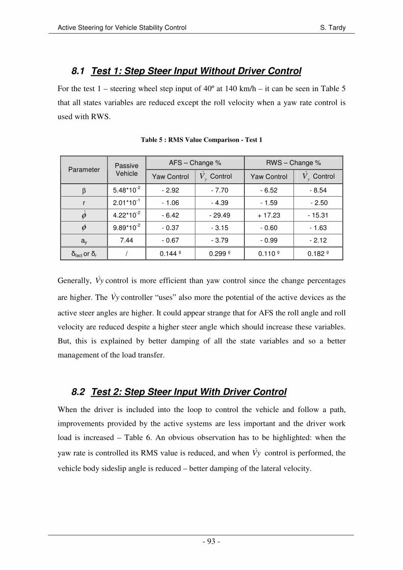
Active Steering for Vehicle Stability Control S. Tardy
- 93 -
8.1 Test 1: Step Steer Input Without Driver Control
For the test 1 – steering wheel step input of 40º at 140 km/h – it can be seen in Table 5
that all states variables are reduced except the roll velocity when a yaw rate control is
used with RWS.
Table 5 : RMS Value Comparison - Test 1
AFS – Change % RWS – Change % Parameter Passive
Vehicle Yaw Control yV& Control Yaw Control yV& Control
β 5.48*10-2 - 2.92 - 7.70 - 6.52 - 8.54
r 2.01*10-1 - 1.06 - 4.39 - 1.59 - 2.50
φ& 4.22*10-2 - 6.42 - 29.49 + 17.23 - 15.31
φ 9.89*10-2 - 0.37 - 3.15 - 0.60 - 1.63
ay 7.44 - 0.67 - 3.79 - 0.99 - 2.12
δfact or δr / 0.144 º 0.299 º 0.110 º 0.182 º
Generally, yV& control is more efficient than yaw control since the change percentages
are higher. The yV& controller “uses” also more the potential of the active devices as the
active steer angles are higher. It could appear strange that for AFS the roll angle and roll
velocity are reduced despite a higher steer angle which should increase these variables.
But, this is explained by better damping of all the state variables and so a better
management of the load transfer.
8.2 Test 2: Step Steer Input With Driver Control
When the driver is included into the loop to control the vehicle and follow a path,
improvements provided by the active systems are less important and the driver work
load is increased – Table 6. An obvious observation has to be highlighted: when the
yaw rate is controlled its RMS value is reduced, and when yV& control is performed, the
vehicle body sideslip angle is reduced – better damping of the lateral velocity.

Active Steering for Vehicle Stability Control S. Tardy
- 94 -
Table 6 : RMS Value Comparison - Test 2
AFS – Change % RWS – Change % Parameter Passive
Vehicle Yaw Control yV& Control Yaw Control yV& Control
β 4.69*10-2 + 0.26 + 1.78 - 2.43 - 4.11
r 1.83*10-1 - 0.05 + 0.47 - 0.89 + 1.41
φ& 3.75*10-2 -4.5 + 1.33 + 14.84 + 3.94
φ 9.17*10-2 - 0.07 - 0.02 + 0.09 + 0.05
ay 6.80 - 0.04 + 0.12 + 0.03 - 0.03
δsw 31.68 + 4.29 + 16.52 + 2.39 + 6.67
δfact or δr 0.15 º 0.44 º 0.07º 0.19 º
Moreover, when yaw rate control is used for RWS, the roll velocity is increased a lot
resulting in comfort degradation for the occupants. For this second test, RWS with yaw
rate control is identified as the most efficient controller which is confirmed by the time
histories discussed in Sections 6.5.2 and 7.5.2. RWS with yV& control would have
improved the vehicle stability by reducing the body sideslip angle, but the yaw rate
response would have been made worse. The overall vehicle stability and driver feeling
is therefore a compromise between yaw rate and body sideslip angle responses when
both cannot be improved together.
8.3 Test 3: Accelerating and Turning
RMS value and change percentages given in Table 7 for the test 3 show that the vehicle
stability is greatly improved when the yaw rate control strategy is used for RWS since
most of the state variables are reduced. Only the roll angle is slightly increased but this
is totally justifiable. Indeed, as seen in 6.5.3, the RWS vehicle stays controllable longer
despite a strong oversteering. The load transfer is so maintained longer – involving a
higher roll angle – in comparison to the other vehicles which are sliding and so reducing
their roll angles as it can be seen in the Figure 100.
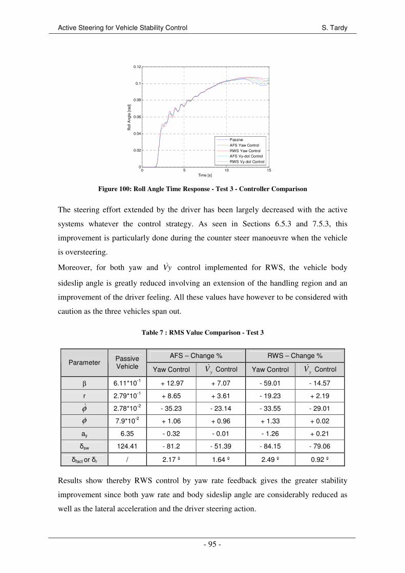
Active Steering for Vehicle Stability Control S. Tardy
- 95 -
0 5 10 150
0.02
0.04
0.06
0.08
0.1
0.12
Time [s]
Rol
l Ang
le [
rad]
Passive
AFS Yaw Control
RWS Yaw ControlAFS Vy-dot Control
RWS Vy-dot Control
Figure 100: Roll Angle Time Response - Test 3 - Controller Comparison
The steering effort extended by the driver has been largely decreased with the active
systems whatever the control strategy. As seen in Sections 6.5.3 and 7.5.3, this
improvement is particularly done during the counter steer manoeuvre when the vehicle
is oversteering.
Moreover, for both yaw and yV& control implemented for RWS, the vehicle body
sideslip angle is greatly reduced involving an extension of the handling region and an
improvement of the driver feeling. All these values have however to be considered with
caution as the three vehicles span out.
Table 7 : RMS Value Comparison - Test 3
AFS – Change % RWS – Change % Parameter Passive
Vehicle Yaw Control yV& Control Yaw Control yV& Control
β 6.11*10-1 + 12.97 + 7.07 - 59.01 - 14.57
r 2.79*10-1 + 8.65 + 3.61 - 19.23 + 2.19
φ& 2.78*10-2 - 35.23 - 23.14 - 33.55 - 29.01
φ 7.9*10-2 + 1.06 + 0.96 + 1.33 + 0.02
ay 6.35 - 0.32 - 0.01 - 1.26 + 0.21
δsw 124.41 - 81.2 - 51.39 - 84.15 - 79.06
δfact or δr / 2.17 º 1.64 º 2.49 º 0.92 º
Results show thereby RWS control by yaw rate feedback gives the greater stability
improvement since both yaw rate and body sideslip angle are considerably reduced as
well as the lateral acceleration and the driver steering action.
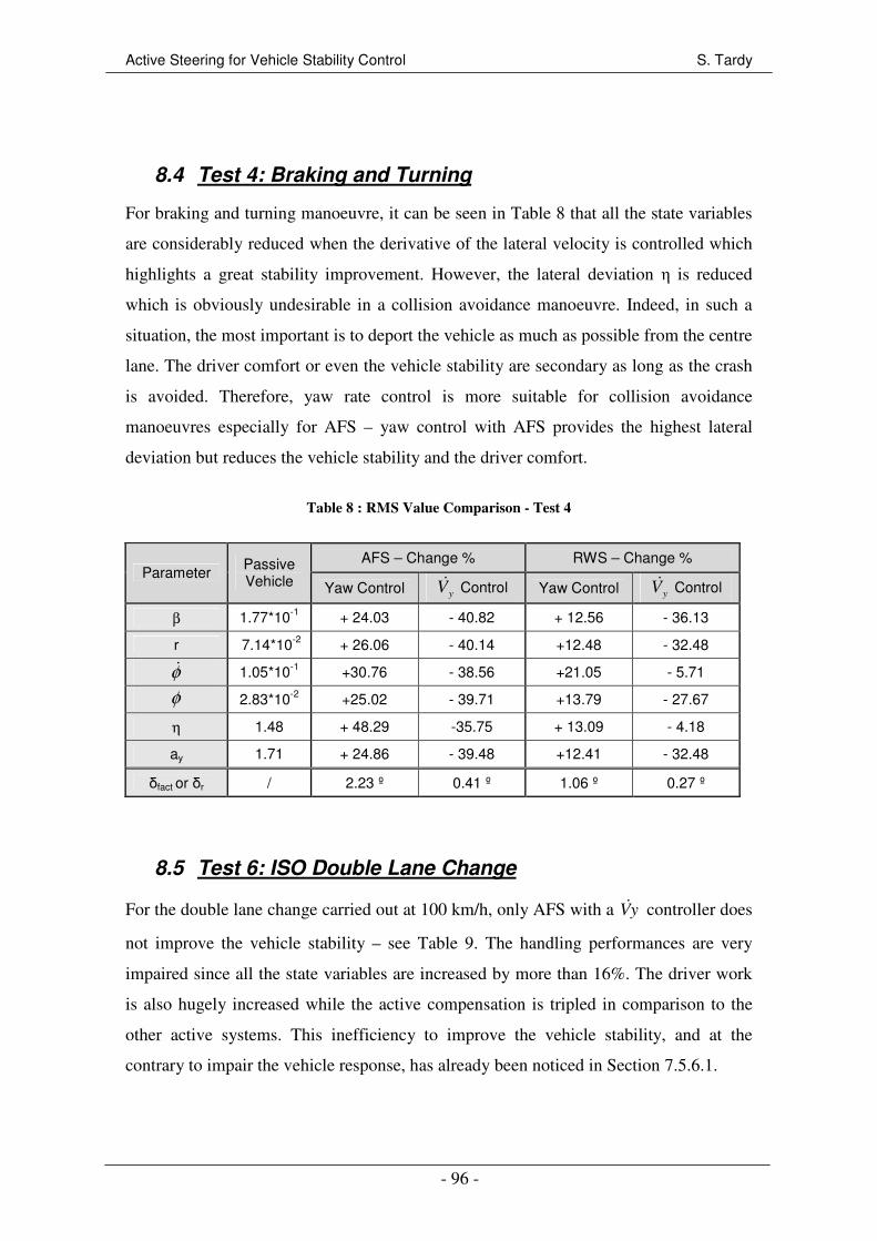
Active Steering for Vehicle Stability Control S. Tardy
- 96 -
8.4 Test 4: Braking and Turning
For braking and turning manoeuvre, it can be seen in Table 8 that all the state variables
are considerably reduced when the derivative of the lateral velocity is controlled which
highlights a great stability improvement. However, the lateral deviation η is reduced
which is obviously undesirable in a collision avoidance manoeuvre. Indeed, in such a
situation, the most important is to deport the vehicle as much as possible from the centre
lane. The driver comfort or even the vehicle stability are secondary as long as the crash
is avoided. Therefore, yaw rate control is more suitable for collision avoidance
manoeuvres especially for AFS – yaw control with AFS provides the highest lateral
deviation but reduces the vehicle stability and the driver comfort.
Table 8 : RMS Value Comparison - Test 4
AFS – Change % RWS – Change % Parameter Passive
Vehicle Yaw Control yV& Control Yaw Control yV& Control
β 1.77*10-1 + 24.03 - 40.82 + 12.56 - 36.13
r 7.14*10-2 + 26.06 - 40.14 +12.48 - 32.48
φ& 1.05*10-1 +30.76 - 38.56 +21.05 - 5.71
φ 2.83*10-2 +25.02 - 39.71 +13.79 - 27.67
η 1.48 + 48.29 -35.75 + 13.09 - 4.18
ay 1.71 + 24.86 - 39.48 +12.41 - 32.48
δfact or δr / 2.23 º 0.41 º 1.06 º 0.27 º
8.5 Test 6: ISO Double Lane Change
For the double lane change carried out at 100 km/h, only AFS with a yV& controller does
not improve the vehicle stability – see Table 9. The handling performances are very
impaired since all the state variables are increased by more than 16%. The driver work
is also hugely increased while the active compensation is tripled in comparison to the
other active systems. This inefficiency to improve the vehicle stability, and at the
contrary to impair the vehicle response, has already been noticed in Section 7.5.6.1.

Active Steering for Vehicle Stability Control S. Tardy
- 97 -
Table 9 : RMS Value Comparison - Test 6
AFS – Change % RWS – Change % Parameter Passive
Vehicle Yaw Control yV& Control Yaw Control yV& Control
β 3.77*10-2 - 44.26 + 46.67 - 30.11 - 47.27
r 2.16*10-1 - 30.77 + 25.72 -18.81 - 22.86
φ& 2.47*10-1 -28.41 + 16.13 -6.64 - 31.04
φ 7.56*10-2 - 24.19 + 18.86 - 9.92 - 19.18
ay 5.057 - 26.35 + 24.28 - 11.21 - 20.56
δsw 34.79 - 34.37 + 177.03 - 26.01 - 4.82
δfact or δr / 0.53º 1.54 º 0.39 º 0.45 º
On the other hand, the three other systems improve significantly the lateral stability as it
can be noticed in Table 9. AFS with yaw rate feedback control gives the higher
improvements in terms of yaw rate, roll angle, lateral acceleration and driver work load.
The body sideslip angle is also greatly reduced – almost by 50%.
8.6 Test 7: High Speed Double Lane Change
For this second double lane change test at high speed – 140 km/h – results given in
Table 10 are quite similar to the previous test. The yV& control strategy applied to AFS
still impairs considerably the lateral responses and makes this controller not suitable at
all for AFS. The body sideslip angle is multiplied by 3.4, the yaw rate by 2 and the
driver steering input by 5.5.
Table 10 : RMS Value Comparison - Test 7
AFS – Change % RWS – Change % Parameter Passive
Vehicle Yaw Control yV& Control Yaw Control yV& Control
β 2.71*10-1 - 4.20 + 238.65 - 5.04 - 37.68
r 1.30*10-1 - 3.34 + 102.62 - 4.34 - 14.24
φ& 1.71*10-1 - 3.51 + 78.15 + 11.11 - 22.14
φ 6.01*10-2 -1.02 + 47.64 + 1.98 - 14.34
ay 3.97 - 1.73 + 55.27 + 1.58 - 15.66
δsw 16.56 + 5.23 + 452.22 - 3.97 + 31.58
δfact or δr / 0.37 º 2.21 º 0.24 º 0.45 º
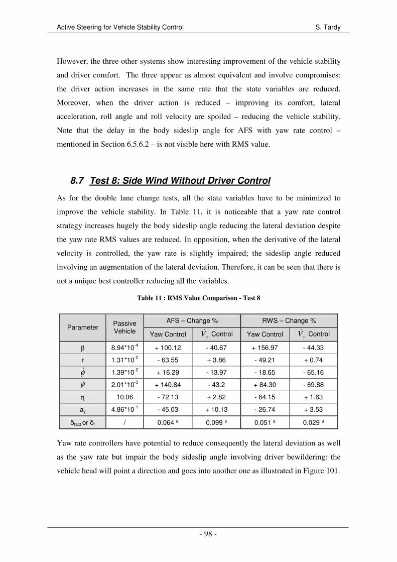
Active Steering for Vehicle Stability Control S. Tardy
- 98 -
However, the three other systems show interesting improvement of the vehicle stability
and driver comfort. The three appear as almost equivalent and involve compromises:
the driver action increases in the same rate that the state variables are reduced.
Moreover, when the driver action is reduced – improving its comfort, lateral
acceleration, roll angle and roll velocity are spoiled – reducing the vehicle stability.
Note that the delay in the body sideslip angle for AFS with yaw rate control –
mentioned in Section 6.5.6.2 – is not visible here with RMS value.
8.7 Test 8: Side Wind Without Driver Control
As for the double lane change tests, all the state variables have to be minimized to
improve the vehicle stability. In Table 11, it is noticeable that a yaw rate control
strategy increases hugely the body sideslip angle reducing the lateral deviation despite
the yaw rate RMS values are reduced. In opposition, when the derivative of the lateral
velocity is controlled, the yaw rate is slightly impaired; the sideslip angle reduced
involving an augmentation of the lateral deviation. Therefore, it can be seen that there is
not a unique best controller reducing all the variables.
Table 11 : RMS Value Comparison - Test 8
AFS – Change % RWS – Change % Parameter Passive
Vehicle Yaw Control yV& Control Yaw Control yV& Control
β 8.94*10-4 + 100.12 - 40.67 + 156.97 - 44.33
r 1.31*10-2 - 63.55 + 3.86 - 49.21 + 0.74
φ& 1.39*10-2 + 16.29 - 13.97 - 18.65 - 65.16
φ 2.01*10-3 + 140.84 - 43.2 + 84.30 - 69.88
η 10.06 - 72.13 + 2.82 - 64.15 + 1.63
ay 4.86*10-1 - 45.03 + 10.13 - 26.74 + 3.53
δfact or δr / 0.064 º 0.099 º 0.051 º 0.029 º
Yaw rate controllers have potential to reduce consequently the lateral deviation as well
as the yaw rate but impair the body sideslip angle involving driver bewildering: the
vehicle head will point a direction and goes into another one as illustrated in Figure 101.
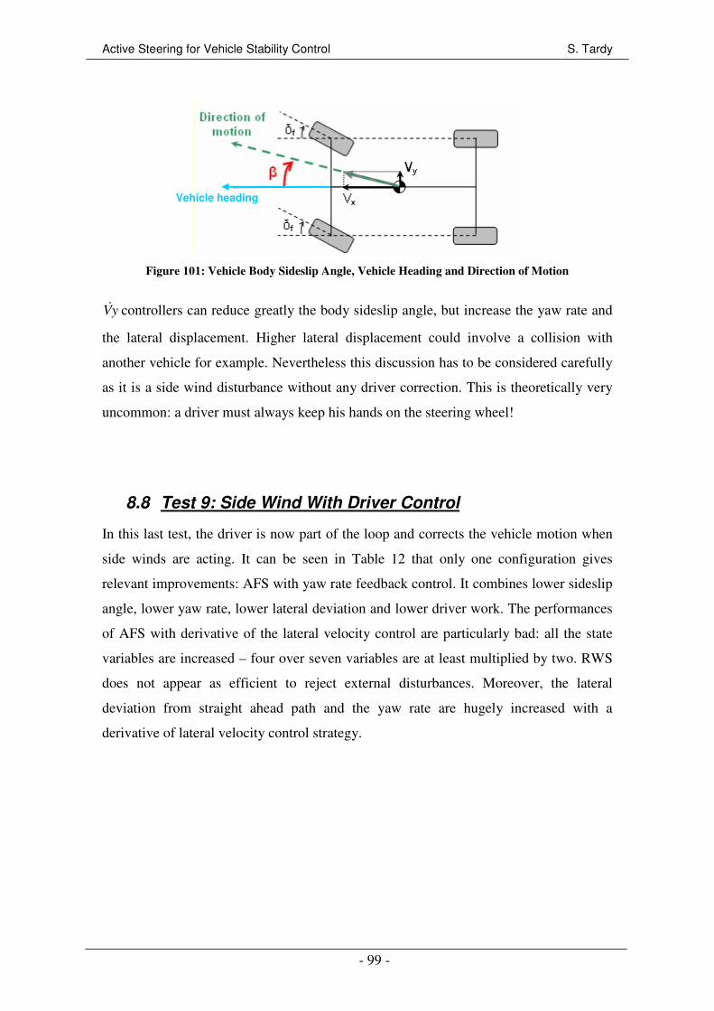
Active Steering for Vehicle Stability Control S. Tardy
- 99 -
Figure 101: Vehicle Body Sideslip Angle, Vehicle Heading and Direction of Motion
yV& controllers can reduce greatly the body sideslip angle, but increase the yaw rate and
the lateral displacement. Higher lateral displacement could involve a collision with
another vehicle for example. Nevertheless this discussion has to be considered carefully
as it is a side wind disturbance without any driver correction. This is theoretically very
uncommon: a driver must always keep his hands on the steering wheel!
8.8 Test 9: Side Wind With Driver Control
In this last test, the driver is now part of the loop and corrects the vehicle motion when
side winds are acting. It can be seen in Table 12 that only one configuration gives
relevant improvements: AFS with yaw rate feedback control. It combines lower sideslip
angle, lower yaw rate, lower lateral deviation and lower driver work. The performances
of AFS with derivative of the lateral velocity control are particularly bad: all the state
variables are increased – four over seven variables are at least multiplied by two. RWS
does not appear as efficient to reject external disturbances. Moreover, the lateral
deviation from straight ahead path and the yaw rate are hugely increased with a
derivative of lateral velocity control strategy.
Vehicle heading

Active Steering for Vehicle Stability Control S. Tardy
- 100 -
Table 12 : RMS Value Comparison - Test 9
AFS – Change % RWS – Change % Parameter Passive
Vehicle Yaw Control yV& Control Yaw Control yV& Control
β 6.2*10-3 - 0.92 + 45.89 + 28.29 - 6.30
r 9.8*10-3 - 10.59 + 281.01 + 16.88 + 98.28
φ& 4.24*10-2 + 0.14 + 33.59 + 10.19 - 20.91
φ 1.76*10-2 - 1.58 + 44.16 + 3.66 + 4.77
η 1.43*10-1 - 11.86 + 189.27 + 11.42 + 76.94
ay 5.65*10-1 - 8.24 + 158.28 + 13.13 + 36.64
δsw 4.03 - 52.11 + 188.03 - 31.68 + 51.10
δfact or δr / 0.12 º 0.39 º 0.10 º 0.11 º
8.9 Closing Comments
This analysis of RMS value and change percentages has pointed aspects which were not
easily noticeable with time responses analyses. The two approaches are complementary
and provide relevant support to compare and evaluate the potential of AFS and RWS to
improve the vehicle stability.
Several results discussed in this chapter have shown that there is not one best controller
which improves the vehicle stability in all the situations. Compromises between lateral
deviation, driver work, comfort or safety, and vehicle stability are necessary.
Nevertheless, it has been noticed that AFS controlled with a derivative of the lateral
speed strategy was not suitable to improve the vehicle stability. This system appeared
efficient only for a step steer input but made worse the vehicle stability in all the other
tests.

Active Steering for Vehicle Stability Control S. Tardy
- 101 -
9 YAW MOMENT CONTROL FOR HANDLING
IMPROVEMENTS
In the three previous chapters, the controllers aimed to improve the vehicle stability
during the transient response while keeping the steady state behaviour as closer as
possible to the passive vehicle. In Section 4.3, it has been mentioned that active steering
could also be used to improve the vehicle handling by achieving a desired steering
response. The objective of this chapter is so to investigate the potential of AFS and
RWS to achieve the performance of a 2-DOF linear model, or those of neutral steering.
In this section, performances of the active steering systems are also compared with
Torque Vectoring Differential (TVD). This study on TVD has been carried out by I.
Olazarri [32] in parallel to this project. However, TVD has not been implemented in
CarMaker. Therefore, the comparison is done in Matlab/Simulink by using the 3-DOF
vehicle model presented in Section 5.1. Several simulations are still done in CarMaker.
The yaw rate feedback controllers introduced in Section 6.1.1 for RWS and Section
6.1.2 for AFS are used – refer to Figure 38 and Figure 39 for the controller layouts.
Only the reference yaw rate subsystem has to be changed.
9.1 Two Degree of Freedom Linear Model Objective
9.1.1 Reference Model
9.1.1.1 Concept
It has been seen in Section 5.1.2 that the lateral vehicle behaviour is mainly damaged by
the non-linearity of the tyres. Therefore, it appears sensible to use a 2-DOF linear
bicycle reference model which can improve this non-linearity. Wheals et al [33] derived

Active Steering for Vehicle Stability Control S. Tardy
- 102 -
a speed dependent function providing the yaw rate as a function of the steer angle input
for a 2-DOF linear model. This function is:
)(22
frxrf
rfx
f
ref
aCbCmVCCl
ClCVr
−+=
δ (10)
The tyre stiffness’s coefficient Cf and Cr are calculated from the product “BCD”
included in the Pacejka’s non-linear tyre model derived for the 3-DOF handling – see
Appendix B.
It has to be noticed that the use of a 2-DOF reference model involves some limits for the
system: linear tyre stiffness coefficient, steady state limitation, and derivation assumed
for small slip angle. Therefore, the reference model has to be tuned to consider these
limitations.
9.1.1.2 Pure Time Delay
Relation (10) accounts only for steady state yaw rates. In a real vehicle, a delay exists
between the steer input and the generation of the yaw rate. Therefore, a pure time delay
Td of 20 ms is added in the reference model: it delays the yaw rate output generated by
the reference model. This delay is implemented in Simulink with the function:
sTdesD−=)( (11)
9.1.1.3 Saturation
A 2-DOF linear model ignores that tyre forces have a finite limit. Therefore, when the
vehicle is in strong non-linearity conditions and the tyres are close to saturation, the
reference yaw rate is too ambitious involving the loss of control. Saturation is so
included by limiting the steering input when the maximum attainable steady state yaw is
reached. As suggest by Hancock [34], this maximum yaw rate can be calculated from:
x
y
V
ar
lim
lim = (12)
aylim is the theoretical limit lateral acceleration that the vehicle can achieve. As
highlighted by Hancock, some vehicles are able to generate a lateral acceleration higher
than 1g, thus a road friction coefficient of 1 could saturate the yaw rate too early. He

Active Steering for Vehicle Stability Control S. Tardy
- 103 -
proposed to define the limit lateral acceleration with a tuneable parameter µHi – sets to
1.03 here:
Hiy ga µ⋅=lim (13)
Finally, the limit steer input can be obtained with:
xV
lr ⋅= lim
limδ (14)
The saturation is added to the “Reference Model” subsystem as illustrated in Figure
102. Note that in this figure, “f(u)” is the function (10).
Figure 102: Two Degree of Freedom Reference Model with Saturation
The tuning of the P+I controller is not presented here. It has been optimized to reduce
the time response without too much overshoot. The final parameters are given in Table
13.
Table 13: P+I Controllers’ Parameters - 2-DOF Reference Model
AFS RWS
Proportional gain – P 0.1 0.1
Integral Time Constant – Ti 0.5 0.4
9.1.2 Performance Analysis
Different tests were carried out to evaluate the performance of this yaw rate feedback
controller using a 2-DOF reference model.

Active Steering for Vehicle Stability Control S. Tardy
- 104 -
9.1.2.1 Cornering Performance at Constant Speed
This first test aimed to characterize the steering response when the vehicle was moving
at constant speed – 140 km/h. The steering angle input was increased by 0.001 rad/s.
This test has been carried out in Simulink with the 3-DOF handling model to compare
AFS and RWS with TVD. The resulting Understeer Diagram is given in Figure 103.
0 1 2 3 4 5 6 7 8 90
0.01
0.02
0.03
0.04
0.05
0.06
0.07
0.08
0.09
0.1
Lateral Acceleration [m/s2]
Ste
erin
g A
ngle
[ra
d]
Passive
AFSRWS
TVD
Figure 103: Understeer Diagram with the 3-DOF Model - 2-DOF Reference Model
It can be seen that when the lateral acceleration exceeds approximately 5 m/s2, the
steering characteristics of the passive vehicle starts to be non-linear. AFS, RWS as well
as TVD extend the linear region of handling to 7.5 m/s2 which is approximately 50%
more than the passive vehicle. Therefore, the active vehicles exhibit less pronounced
non-linear steering characteristics in the high lateral acceleration range leading to a
vehicle that will handle in a more predictable manner in higher lateral accelerations.
However, the maximal lateral acceleration that the vehicle can generate is reduced by
0.32 m/s2 with RWS and TVD – by 0.53 m/s
2 with AFS – which could be undesirable
for a sport vehicle and frustrating for drivers looking for sensations.
9.1.2.2 Step Steer Inputs
The vehicles responses to step steer inputs are investigated in this section. In a first time
the step input is set to 0.03 rad when the vehicle is moving at 140 km/h. Figure 104
compares the yaw rate time histories of the passive vehicle, with AFS, RWS and TVD;
the reference yaw rate is also included. Note that these results are generated in Simulink
with the 3-DOF vehicle model.

Active Steering for Vehicle Stability Control S. Tardy
- 105 -
0 0.5 1 1.5 2 2.5 3 3.5 40
0.05
0.1
0.15
0.2
0.25
0.3
Time [s]
Yaw
Rat
e [r
ad/s
]Steer Input = 0.03rad
Reference
Passive
AFSRWS
TVD
Figure 104: Yaw Rate Time Response with 3-
DOF Vehicle Model - 0.03rad Step Steer Input -
2-DOF Reference Model
0 0.5 1 1.5 2 2.5 3 3.5 40
0.05
0.1
0.15
0.2
0.25
0.3
Time [s]
Yaw
Rat
e [r
ad/s
]
Reference
Passive
AFS
RWS
Figure 105: Yaw Rate Response with CarMaker
Vehicle Model - 0.03rad Step Steer Input - 2-DOF
Reference Model
It can be seen that the yaw rate response is greatly improved with AFS and RWS. In
spite of the first overshoot is increased by 10%, the settling time is reduced from 1.53 s
to 0.24 s with RWS and to 0.21 s with AFS. The vehicle responsiveness is so improved
and the active steering vehicles are less understeering: the steady state yaw rates are
increased by almost 20%. Concerning TVD, the handling behaviour is also enhanced
since the steady state yaw rate is increased. However, TVD makes the yaw rate response
more oscillatory and so damages the vehicle stability.
This step steer test has also been carried out with the vehicle model in CarMaker for
AFS and RWS. The yaw rate responses are shown in Figure 105. Responses are quite
similar to those obtained with the 3-DOF vehicle model. However they are more
oscillatory, even for the passive vehicle. This is due to the better accuracy of the vehicle
model which includes for example the suspension kinematics and a more relevant
representation of the weight transfer. It has also to be noticed that the reference yaw rate
is slightly lower when the simulation is done in CarMaker than with the 3-DOF model.
This is due to the speed diminution when the vehicle turns – not considered by the 3-
DOF model.
The two previous simulations have been done with a pure step steer input which is not
conceivable in reality. Therefore, a ramp steer input – duration 1 s, amplitude 0.03 rad –
is used to generate time histories given in Figure 106. It can be noticed that by making
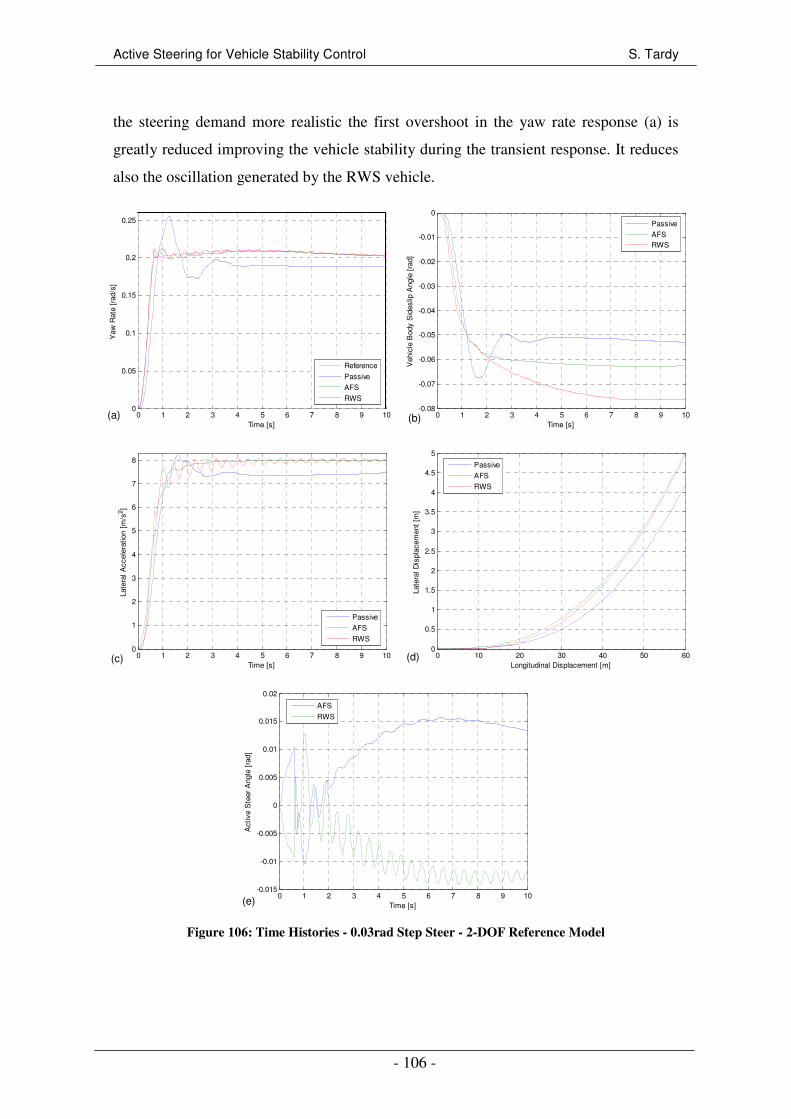
Active Steering for Vehicle Stability Control S. Tardy
- 106 -
the steering demand more realistic the first overshoot in the yaw rate response (a) is
greatly reduced improving the vehicle stability during the transient response. It reduces
also the oscillation generated by the RWS vehicle.
0 1 2 3 4 5 6 7 8 9 100
0.05
0.1
0.15
0.2
0.25
Time [s]
Yaw
Rat
e [r
ad/s
]
Reference
Passive
AFS
RWS
0 1 2 3 4 5 6 7 8 9 10-0.08
-0.07
-0.06
-0.05
-0.04
-0.03
-0.02
-0.01
0
Time [s]
Veh
icle
Bod
y S
ides
lip A
ngle
[ra
d]
Passive
AFSRWS
0 1 2 3 4 5 6 7 8 9 100
1
2
3
4
5
6
7
8
Time [s]
Late
ral A
ccel
erat
ion
[m/s
2 ]
Passive
AFS
RWS
0 10 20 30 40 50 600
0.5
1
1.5
2
2.5
3
3.5
4
4.5
5
Longitudinal Displacement [m]
Late
ral D
ispl
acem
ent
[m]
Passive
AFS
RWS
0 1 2 3 4 5 6 7 8 9 10-0.015
-0.01
-0.005
0
0.005
0.01
0.015
0.02
Time [s]
Act
ive
Ste
er A
ngle
[ra
d]
AFS
RWS
Figure 106: Time Histories - 0.03rad Step Steer - 2-DOF Reference Model
(a) (b)
(c) (d)
(e)
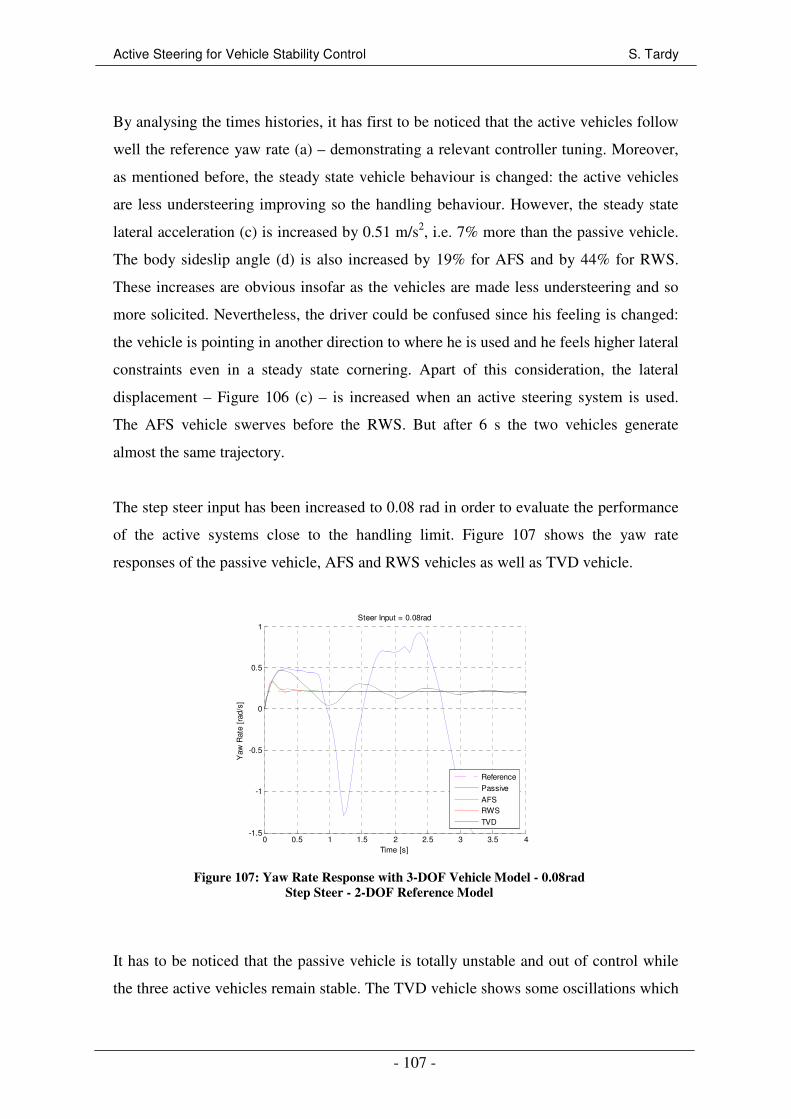
Active Steering for Vehicle Stability Control S. Tardy
- 107 -
By analysing the times histories, it has first to be noticed that the active vehicles follow
well the reference yaw rate (a) – demonstrating a relevant controller tuning. Moreover,
as mentioned before, the steady state vehicle behaviour is changed: the active vehicles
are less understeering improving so the handling behaviour. However, the steady state
lateral acceleration (c) is increased by 0.51 m/s2, i.e. 7% more than the passive vehicle.
The body sideslip angle (d) is also increased by 19% for AFS and by 44% for RWS.
These increases are obvious insofar as the vehicles are made less understeering and so
more solicited. Nevertheless, the driver could be confused since his feeling is changed:
the vehicle is pointing in another direction to where he is used and he feels higher lateral
constraints even in a steady state cornering. Apart of this consideration, the lateral
displacement – Figure 106 (c) – is increased when an active steering system is used.
The AFS vehicle swerves before the RWS. But after 6 s the two vehicles generate
almost the same trajectory.
The step steer input has been increased to 0.08 rad in order to evaluate the performance
of the active systems close to the handling limit. Figure 107 shows the yaw rate
responses of the passive vehicle, AFS and RWS vehicles as well as TVD vehicle.
0 0.5 1 1.5 2 2.5 3 3.5 4-1.5
-1
-0.5
0
0.5
1
Time [s]
Yaw
Rat
e [r
ad/s
]
Steer Input = 0.08rad
ReferencePassive
AFSRWS
TVD
Figure 107: Yaw Rate Response with 3-DOF Vehicle Model - 0.08rad
Step Steer - 2-DOF Reference Model
It has to be noticed that the passive vehicle is totally unstable and out of control while
the three active vehicles remain stable. The TVD vehicle shows some oscillations which
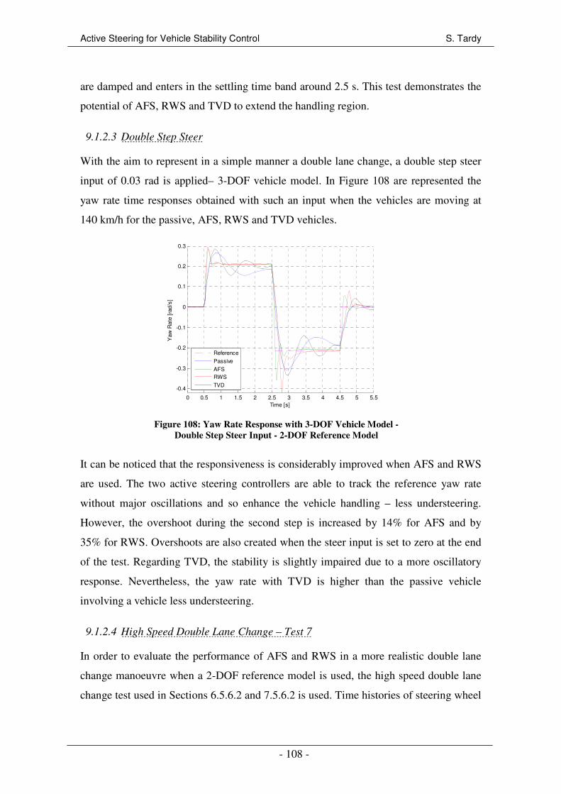
Active Steering for Vehicle Stability Control S. Tardy
- 108 -
are damped and enters in the settling time band around 2.5 s. This test demonstrates the
potential of AFS, RWS and TVD to extend the handling region.
9.1.2.3 Double Step Steer
With the aim to represent in a simple manner a double lane change, a double step steer
input of 0.03 rad is applied– 3-DOF vehicle model. In Figure 108 are represented the
yaw rate time responses obtained with such an input when the vehicles are moving at
140 km/h for the passive, AFS, RWS and TVD vehicles.
0 0.5 1 1.5 2 2.5 3 3.5 4 4.5 5 5.5
-0.4
-0.3
-0.2
-0.1
0
0.1
0.2
0.3
Time [s]
Yaw
Rat
e [r
ad/s
]
Reference
Passive
AFSRWS
TVD
Figure 108: Yaw Rate Response with 3-DOF Vehicle Model -
Double Step Steer Input - 2-DOF Reference Model
It can be noticed that the responsiveness is considerably improved when AFS and RWS
are used. The two active steering controllers are able to track the reference yaw rate
without major oscillations and so enhance the vehicle handling – less understeering.
However, the overshoot during the second step is increased by 14% for AFS and by
35% for RWS. Overshoots are also created when the steer input is set to zero at the end
of the test. Regarding TVD, the stability is slightly impaired due to a more oscillatory
response. Nevertheless, the yaw rate with TVD is higher than the passive vehicle
involving a vehicle less understeering.
9.1.2.4 High Speed Double Lane Change – Test 7
In order to evaluate the performance of AFS and RWS in a more realistic double lane
change manoeuvre when a 2-DOF reference model is used, the high speed double lane
change test used in Sections 6.5.6.2 and 7.5.6.2 is used. Time histories of steering wheel
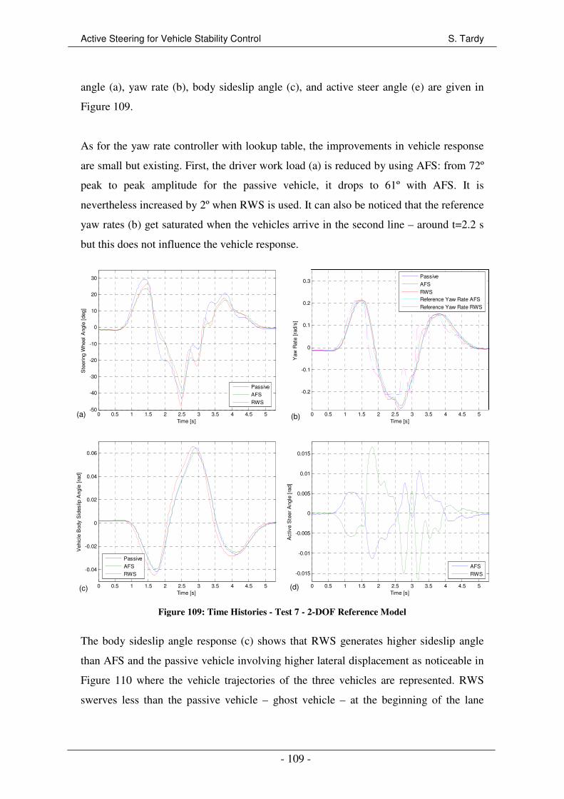
Active Steering for Vehicle Stability Control S. Tardy
- 109 -
angle (a), yaw rate (b), body sideslip angle (c), and active steer angle (e) are given in
Figure 109.
As for the yaw rate controller with lookup table, the improvements in vehicle response
are small but existing. First, the driver work load (a) is reduced by using AFS: from 72º
peak to peak amplitude for the passive vehicle, it drops to 61º with AFS. It is
nevertheless increased by 2º when RWS is used. It can also be noticed that the reference
yaw rates (b) get saturated when the vehicles arrive in the second line – around t=2.2 s
but this does not influence the vehicle response.
0 0.5 1 1.5 2 2.5 3 3.5 4 4.5 5-50
-40
-30
-20
-10
0
10
20
30
Time [s]
Ste
erin
g W
heel
Ang
le [
deg]
Passive
AFS
RWS
0 0.5 1 1.5 2 2.5 3 3.5 4 4.5 5
-0.2
-0.1
0
0.1
0.2
0.3
Time [s]
Yaw
Rat
e [r
ad/s
]
Passive
AFS
RWSReference Yaw Rate AFS
Reference Yaw Rate RWS
0 0.5 1 1.5 2 2.5 3 3.5 4 4.5 5
-0.04
-0.02
0
0.02
0.04
0.06
Time [s]
Veh
icle
Bod
y S
ides
lip A
ngle
[ra
d]
Passive
AFS
RWS
0 0.5 1 1.5 2 2.5 3 3.5 4 4.5 5
-0.015
-0.01
-0.005
0
0.005
0.01
0.015
Time [s]
Act
ive
Ste
er A
ngle
[ra
d]
AFS
RWS
Figure 109: Time Histories - Test 7 - 2-DOF Reference Model
The body sideslip angle response (c) shows that RWS generates higher sideslip angle
than AFS and the passive vehicle involving higher lateral displacement as noticeable in
Figure 110 where the vehicle trajectories of the three vehicles are represented. RWS
swerves less than the passive vehicle – ghost vehicle – at the beginning of the lane
(a) (b)
(c) (d)
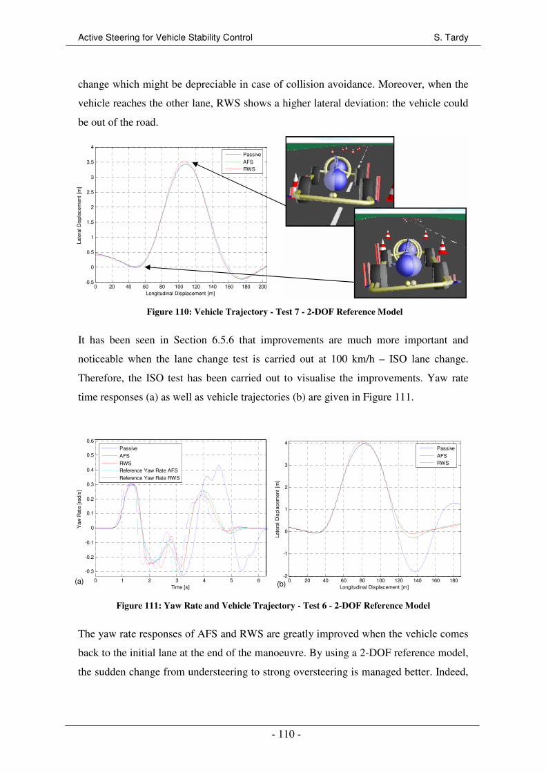
Active Steering for Vehicle Stability Control S. Tardy
- 110 -
change which might be depreciable in case of collision avoidance. Moreover, when the
vehicle reaches the other lane, RWS shows a higher lateral deviation: the vehicle could
be out of the road.
0 20 40 60 80 100 120 140 160 180 200-0.5
0
0.5
1
1.5
2
2.5
3
3.5
4
Longitudinal Displacement [m]
Late
ral D
ispl
acem
ent
[m]
Passive
AFSRWS
Figure 110: Vehicle Trajectory - Test 7 - 2-DOF Reference Model
It has been seen in Section 6.5.6 that improvements are much more important and
noticeable when the lane change test is carried out at 100 km/h – ISO lane change.
Therefore, the ISO test has been carried out to visualise the improvements. Yaw rate
time responses (a) as well as vehicle trajectories (b) are given in Figure 111.
0 1 2 3 4 5 6
-0.3
-0.2
-0.1
0
0.1
0.2
0.3
0.4
0.5
0.6
Time [s]
Yaw
Rat
e [r
ad/s
]
Passive
AFS
RWSReference Yaw Rate AFS
Reference Yaw Rate RWS
0 20 40 60 80 100 120 140 160 180-2
-1
0
1
2
3
4
Longitudinal Displacement [m]
Late
ral D
ispl
acem
ent
[m]
Passive
AFSRWS
Figure 111: Yaw Rate and Vehicle Trajectory - Test 6 - 2-DOF Reference Model
The yaw rate responses of AFS and RWS are greatly improved when the vehicle comes
back to the initial lane at the end of the manoeuvre. By using a 2-DOF reference model,
the sudden change from understeering to strong oversteering is managed better. Indeed,
(a) (b)

Active Steering for Vehicle Stability Control S. Tardy
- 111 -
the reduction of understeering in the first part of the manoeuvre – lower yaw rate –
reduces the curt load transfer when the vehicle returns to the initial lane.
9.1.2.5 Accelerating and Turning – Test 3
This test has been introduced in Sections 6.5.3 and 7.5.3. It consists of accelerating the
vehicle from 100 km/h with an acceleration of 1.7 m/s2 – see Figure 112 (a) – until the
loss of control. Time histories are shown in Figure 112 for the passive vehicle as well as
for the AFS and RWS vehicles.
0 2 4 6 8 10 12 14 160
50
100
150
Time [s]
For
war
d V
eloc
ity [
km/h
]
Passive
AFS
RWS
0 2 4 6 8 10 12 14 16
-250
-200
-150
-100
-50
0
50
Time [s]
Ste
erin
g W
heel
Ang
le [
deg]
Passive
AFSRWS
0 2 4 6 8 10 12 14 16
-0.1
0
0.1
0.2
0.3
0.4
0.5
0.6
0.7
Time [s]
Yaw
Rat
e [r
ad/s
]
Passive
AFS
RWSReference Yaw Rate AFS
Reference Yaw Rate RWS
0 2 4 6 8 10 12 14 16
-2
-1.5
-1
-0.5
0
Time [s]
Veh
icle
Bod
y S
ides
lip A
ngle
[ra
d]
Passive
AFS
RWS
(a) (b)
(c) (d)
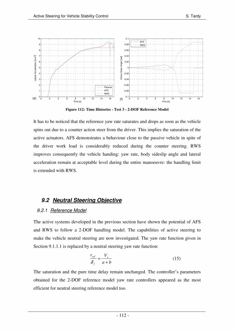
Active Steering for Vehicle Stability Control S. Tardy
- 112 -
0 2 4 6 8 10 12 14 160
1
2
3
4
5
6
7
8
9
10
Time [s]
Late
ral A
ccel
erat
ion
[m/s
2 ]
Passive
AFS
RWS
0 2 4 6 8 10 12 14 16-0.1
-0.08
-0.06
-0.04
-0.02
0
0.02
0.04
0.06
0.08
0.1
Time [s]
Act
ive
Ste
er A
ngle
[ra
d]
AFS
RWS
Figure 112: Time Histories - Test 3 - 2-DOF Reference Model
It has to be noticed that the reference yaw rate saturates and drops as soon as the vehicle
spins out due to a counter action steer from the driver. This implies the saturation of the
active actuators. AFS demonstrates a behaviour close to the passive vehicle in spite of
the driver work load is considerably reduced during the counter steering. RWS
improves consequently the vehicle handing: yaw rate, body sideslip angle and lateral
acceleration remain at acceptable level during the entire manoeuvre: the handling limit
is extended with RWS.
9.2 Neutral Steering Objective
9.2.1 Reference Model
The active systems developed in the previous section have shown the potential of AFS
and RWS to follow a 2-DOF handling model. The capabilities of active steering to
make the vehicle neutral steering are now investigated. The yaw rate function given in
Section 9.1.1.1 is replaced by a neutral steering yaw rate function:
ba
Vrx
f
ref
+=
δ (15)
The saturation and the pure time delay remain unchanged. The controller’s parameters
obtained for the 2-DOF reference model yaw rate controllers appeared as the most
efficient for neutral steering reference model too.
(f) (e)
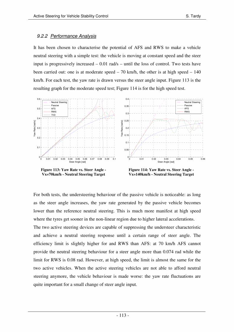
Active Steering for Vehicle Stability Control S. Tardy
- 113 -
9.2.2 Performance Analysis
It has been chosen to characterise the potential of AFS and RWS to make a vehicle
neutral steering with a simple test: the vehicle is moving at constant speed and the steer
input is progressively increased – 0.01 rad/s – until the loss of control. Two tests have
been carried out: one is at moderate speed – 70 km/h, the other is at high speed – 140
km/h. For each test, the yaw rate is drawn versus the steer angle input. Figure 113 is the
resulting graph for the moderate speed test; Figure 114 is for the high speed test.
0 0.01 0.02 0.03 0.04 0.05 0.06 0.07 0.08 0.09 0.10
0.1
0.2
0.3
0.4
0.5
0.6
Steer Angle [rad]
Yaw
Rat
e [r
ad/s
]
Neutral Steering
Passive
AFSRWS
TVD
Figure 113: Yaw Rate vs. Steer Angle -
Vx=70km/h - Neutral Steering Target
0 0.01 0.02 0.03 0.04 0.05 0.060
0.05
0.1
0.15
0.2
0.25
0.3
0.35
0.4
Steer Angle [rad]
Yaw
Rat
e [r
ad/s
]
Neutral Steering
PassiveAFS
RWS
Figure 114: Yaw Rate vs. Steer Angle -
Vx=140km/h - Neutral Steering Target
For both tests, the understeering behaviour of the passive vehicle is noticeable: as long
as the steer angle increases, the yaw rate generated by the passive vehicle becomes
lower than the reference neutral steering. This is much more manifest at high speed
where the tyres get sooner in the non-linear region due to higher lateral accelerations.
The two active steering devices are capable of suppressing the understeer characteristic
and achieve a neutral steering response until a certain range of steer angle. The
efficiency limit is slightly higher for and RWS than AFS: at 70 km/h AFS cannot
provide the neutral steering behaviour for a steer angle more than 0.074 rad while the
limit for RWS is 0.08 rad. However, at high speed, the limit is almost the same for the
two active vehicles. When the active steering vehicles are not able to afford neutral
steering anymore, the vehicle behaviour is made worse: the yaw rate fluctuations are
quite important for a small change of steer angle input.
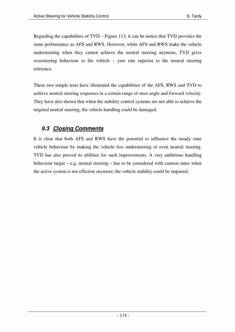
Active Steering for Vehicle Stability Control S. Tardy
- 114 -
Regarding the capabilities of TVD – Figure 113, it can be notice that TVD provides the
same performance as AFS and RWS. However, while AFS and RWS make the vehicle
understeering when they cannot achieve the neutral steering anymore, TVD gives
oversteering behaviour to the vehicle – yaw rate superior to the neutral steering
reference.
These two simple tests have illustrated the capabilities of the AFS, RWS and TVD to
achieve neutral steering responses in a certain range of steer angle and forward velocity.
They have also shown that when the stability control systems are not able to achieve the
targeted neutral steering, the vehicle handling could be damaged.
9.3 Closing Comments
It is clear that both AFS and RWS have the potential to influence the steady state
vehicle behaviour by making the vehicle less understeering or even neutral steering.
TVD has also proved its abilities for such improvements. A very ambitious handling
behaviour target – e.g. neutral steering – has to be considered with caution since when
the active system is not efficient anymore; the vehicle stability could be impaired.
Active Steering for Vehicle Stability Control S. Tardy
- 115 -
10 CONCLUSIONS
Most of the objectives defined at the beginning of the project have been achieved. The
three control strategies investigated in this report – yaw rate feedback control, derivative
of the lateral velocity and reference model tracking – have clearly shown the potential
of Active Front Steering (AFS) and Rear Wheel Steering (RWS) to improve the vehicle
stability as well as the handling behaviour. The influence of the actuator and the driver
interaction constitutes also an interesting founding.
10.1 Influence of the Actuator, Interaction with the Driver
It has been shown that a low bandwidth actuator could generate an oscillatory behaviour
even in a straight line when steer actions are minor. The investigation has demonstrated
that is due to a counter reaction of the driver who feels the correction generated by the
active system – the oscillations were not noticeable with a simple driver model which
did not consider any feedback from the vehicle. It has so been proposed that a
bandwidth around 13 Hz would be appropriate knowing it involves quite a high
performance actuator. This investigation on the actuator and the interaction with the
driver has finally shown that it is important to consider and integrate an advanced driver
model to carry out relevant analyses about active steering. Moreover, it has often been
noticed that the driver action works against the active devices making worse the vehicle
response, particularly with AFS.
10.2 Stability Improvement
In this study, the focus has been on the capabilities of AFS and RWS to improve the
vehicle stability by investigating two different control strategies: yaw rate feedback
control with a look-up table and minimization of the derivative of the lateral velocity
control. Both improve the vehicle stability while the steady state behaviour is kept as
closer as possible to the passive vehicle to not impair the driver enjoyment. It has been
found that the two active systems demonstrate great potential. The nine typical tests
Active Steering for Vehicle Stability Control S. Tardy
- 116 -
which have been carried out have allowed a relevant evaluation of the performance of
each systems as well as comparison with the passive front wheel steering vehicle.
Results have been consolidated by Root Mean Square value comparisons. However, it
has been discussed that there is not only one best control strategy: when one is efficient,
the other could impair the vehicle stability. The final choice of a controller strategy
depends considerably on the design objectives fixed for the vehicle. Nevertheless,
practical considerations are important: the yaw rate feedback control strategy is based
on a look-up table which limit the range of utilisation since the controller has to be
improved to consider vehicle parameter changes or variations in the road friction
coefficient. In opposition, the derivative of the lateral speed strategy is applicable for
all vehicles and is not influence by vehicle parameters or road friction coefficient
changes. This strategy uses variables “easily” measurable. Finally, some general
characteristics implied by active steering can be summed-up as follow:
- Better damped response and lower settling time.
- Reduction of the driver work in most of the situations.
- Rejection of external disturbances as side wind excitations and reduction of the
lateral deviation from straight ahead path.
- Increase of the lateral deviation in case of collision avoidance manoeuvres.
10.3 Handling Behaviour Improvement
The capabilities of AFS and RWS to improve the handling behaviour by making the
vehicle less understeering or even neutral steering are important. The linear handling
region can be extending with both AFS and RWS. However, non-linearity has to be
considered in the reference model to avoid a premature saturation of the tyre and so
avoid degradation of the handling behaviour close to the handling limit.
Moreover, is spite of active steering systems are able to improve the lateral behaviour,
they are not able to push back the handling limit when a two degree of freedom or
neutral steering references models are used.
Finally, this objective – improve the vehicle handling behaviour – may appear as not so
relevant since it could impair the driver enjoyment by suppressing all understeering or
Active Steering for Vehicle Stability Control S. Tardy
- 117 -
oversteering conditions. Obviously, such a strategy could be interesting for a certain
range of luxury vehicle where comfort and safety are the most important criterion.
10.4 Recommendations: “AFS or RWS?”
It is difficult to recommend a system more than the other since both demonstrate
important improvements in the vehicle stability. Each system shows advantages and/or
weaknesses. AFS is very efficient to reject external disturbances while it does not
provide any improvements in a situation of accelerating and turning. On the other hand,
RWS helps considerably the driver in a turn at high speed in spite of it fails to reject
disturbances. Moreover, it has to be highlighted that a derivative of the lateral speed
control strategy is not suitable at all for AFS since this system has shown significant
degradations in the vehicle stability and handing behaviour. AFS and the driver have
often shown undesirable interaction making worse the vehicle stability too.
Nevertheless, to conclude, both Active Front Steering and Rear Wheel Steering appear
as suitable for a new control stability device in a future sedan vehicle. The choice
depends mainly on the objective fixed for the overall vehicle design.
10.5 Future Work
Some further investigations could be interesting in order to analyse some aspects which
have not been considered in this study. These recommended works are list below:
- Integrate an adaptive control in the yaw rate feedback controller with look-up table to
consider changes in vehicle parameters and road friction coefficient. This would also
involve the development of a system aiming to evaluate the road friction coefficient.
- P+I controllers give more than acceptable results, however the development of a
more advanced controller using LQR or H-∞ Theory should be pertinent to increase
the controller robustness and optimise its action.
- IPG CarMaker provides a toolbox to integrate sensors in order to measure state
variables. Thus, the implementations of the controllers could be improved and made
closer to the reality by adding sensors in the model to measure all the state variables
needed, instead of using CarMaker’s accessible variables.

Active Steering for Vehicle Stability Control S. Tardy
- 118 -
- Investigate the potential of a Dual Steering Scheme to improve the vehicle stability.
By controlling two state variables – e.g. yaw rate and derivative of the lateral
velocity – it could be possible to combine the benefits of both Active Front Steering
and Rear Wheel Steering in the same vehicle.
- As the front and/or rear steering system is a crucial component for the vehicle safety,
the fail safe of the system – mechanical and electronic – should be considered in a
deeper analysis. That could be start by investigating alternative or error flows in the
Use Case.
- The undesirable interactions between the driver and the active steering systems have
been pointed often in this study and some assumptions have been proposed to
understand the results. Test in a real vehicle with a real driver could confirm the
interaction but also give a better understanding of the driver reaction.
- Finally, it could be interesting to investigate the combination of active steering with
other stability control devices as Roll Moment Distribution to provide a better
management of the load transfer which influence the lateral tyres forces.

Active Steering for Vehicle Stability Control S. Tardy
- 119 -
REFERENCES
[1] Sano, S., Furukawa, Y., and Shiraishi, S., “Four Wheel Steering System with Rear
Wheel Steer Angle Controlled as a Function of Steering Wheel Angle”. SAE paper
86-0625, 1986.
[2] Nikzad, S., V., and Naraghi, M., “Model Reference Tracking Control of a 4WS
Vehicle Using Single and Dual Steering Strategies”. SAE paper 2002-01-1590,
2002.
[3] Furukawa, Y., Yuhara, N., Sano, S., Takeda, H., and Matsushita, Y., “A Review
of Four-Wheel-Steering Studies from the Viewpoint of Vehicle Dynamics Control”.
Vehicle System Dynamics, Vol. 18, No.1-3, 1989, p151-186.
[4] Pascali, L., Gabrielli, P., and Caviasso, G, “Improving Vehicle Handling and
Comfort Performance Using 4WS”. SAE paper 2003-01-0961, 2003.
[5] Nalecz, A., G., and Bindemann, A., C., “Handling Properties of Four Wheel
Steering Vehicles”. SAE paper 89-0080, 1989.
[6] Morgando, A., Velardocchia, M., Danesin, D., and Rossi, E., “An Innovative
Control Logic for a Four-Wheel-Steer Vehicle. Part 1: Analysis and Design”. SAE
paper 2005-01-1267, 2005.
[7] Akita, T., Satoh, K., and Gaunt, M. C., ”Development of 4WS Control Algorithm
for a SUV”. SAE paper 2002-01-1216, 2002.
[8] Whitehead, J. C., “Four Wheel Steering: Manoeuvrability and High Speed
Stabilization”. SAE paper 88-0642, 1988.
[9] Xia, X., and Law, E. H., “Nonlinear Dynamic Response of Four Wheel Steering
Automobiles to Combined Braking and Steering Commands on Collision Avoidance
Maneuvers“. SAE paper 90-1731, 1990.
Active Steering for Vehicle Stability Control S. Tardy
- 120 -
[10] Lee, A. L., “Performance of 14’our-Wheel-Steering Vehicles in Lane Change
Maneuvers”. Jet Propulsion Laboratory, Pasadena, California, 1994.
http://trs-new.jpl.nasa.gov/dspace/bitstream/2014/34626/1/94-0981.pdf
[11] Hirano, Y., Harada, H., Ono, E., and Takanami, K., “Development of an
Integrated System of 4WS and 4WD by H-∞ Control”. SAE paper 93-0267, 1993.
[12] Lv, H-M., Chen, N., and Li, P., “Multi-Objective H∞ Optimal Control for Four-
Wheel-Steering Vehicle Based on Yaw Rate Tracking”. IMechE, Journal of
Automobile Engineering, Vol. 218, Part D10, 2004, p. 1117-1123.
[13] You, S-S., and Jeong, S. K., “Vehicle Dynamics and Control Synthesis for Four-
Wheel-Steering Passenger Cars”. IMechE, Journal of Automobile Engineering, Vol.
212, Part D6, 1998, p. 449-461.
[14] El-Nashar, M. A., Abdelhady, M. B., Oraby, W. A., and El-Sinawy, S. R.,
“Enhanced Vehicle Lateral Stability in Crosswind by Limited State Kalman Filter
Four-Wheel-Steering System”. SAE paper 2007-01-0841, 2007.
[15] Ozatay, E., Unlusoy, S. Y., and Murat Yildirim, A., “Enhancement of Vehicle
Handling Using Four-Wheel-Steering Control Strategy”. SAE paper 2006-01-0942,
2006.
[16] Nikzad S., V., and Naraghi, M., “Time Delay Control of a 4WS Vehicle - A
Comparison of Single and Dual Steering Control Strategies”. SAE paper 2002-01-
1589, 2002.
[17] Aga, M., Kusunoki, H., Satoh, Y., Saitoh, R., and Ito, M., “Design of Two-
Degree-of-Freedom Control System for Active Front-and-Rear-Wheel Steering”.
SAE paper 90-1746, 1990.
[18] Palkovics, L., “Effect of the Controller Parameters on the Steerability of the Four
Wheel Steered Car”. Vehicle System Dynamics, Vol. 21, No.2, 1992, p109-128.
Active Steering for Vehicle Stability Control S. Tardy
- 121 -
[19] P. Koehn and M. Eckrich, “Active Steering – The BMW Approach Towards
Modern Steering Technology”. SAE paper 2004-01-1105, 2004.
[20] W. Klier, G. Reinmann and W. Reinelt, “Concept and Functionality of the Active
Front Steering System”. SAE paper 2004-21-0073, 2004.
[21] W. Reinelt, W. Klier, G. Reinmann, W. Schuster and R. Grobheim, “Active
Steering (Part 2): Safety and Functionality”. SAE paper 2004-01-1101, 2004.
[22] Oraby, W., A., H., El-Demerdash, S., M., Selim, A., M., Faizz, A., and Crolla,
D., A., “Improvement of Vehicle Lateral Dynamics by Active Front Steering
Control”. SAE paper 2004-01-2081, 2004.
[23] Mammar, S., and Koening, D., “Vehicle Handling Improvement by Active
Steering”. Vehicle System Dynamics, Vol. 38, No.3, 2002, p. 211-242.
[24] He, J., Crolla, D., A., Levesley, M., C., and Manning, W., J., “Coordination of
Active Steering, Driveline, and Braking for Integrated Vehicle Dynamics Control”.
IMechE, Journal of Automobile Engineering, Vol. 220, Part D, 2006, p. 1401-1421.
[25] IPG Automotive GmbH, “CarMaker Workshop 14th
Dec 06”. PowerPoint
Presentation, 2006.
[26] IPG Automotive GmbH, “CarMaker User’s Guide”, Version 2.1.5.
[27] IPG Automotive GmbH, “CarMaker Reference Manual”, Version 2.1.9.
[28] IPG Automotive GmbH, “CarMaker Programmer’s Guide”, Version 2.1.11.
[29] B. Gebhard, and M. Rappl, “Requirements Management for Automotive Systems
Development”. SAE paper 2000-01-0716, 2000.
[30] A. Cockburn, “Writing Effective Use Cases”, The Crystal Collection for Software
Professionals, Addison-Wesley, 2001.
Active Steering for Vehicle Stability Control S. Tardy
- 122 -
[31] T. Yamanaka, A. Taneda, and S. Tanizaki, “Development of the Actuator for
ARS System”. Ref 98AE004, ISATA – Automotive Electronics and New Products,
Düsseldorf, Germany, 1998.
[32] I. Olazarri Madariaga, “Torque Vectoring Differential for Vehicle Stability
Control”. MSc Thesis, Cranfield University, to be published in 2007.
[33] J. C. Wheals, H. Baker, K. Ramsey and W. Turner, “Torque Vectoring AWD
Driveline: Design, Simulation, Capabilities and Control”. SAE paper 2004-01-0863,
2004.
[34] M. Hancock, “Vehicle Handling Control Using Active Differentials”. Doctoral
Thesis, Loughborough University, 2006.
[35] H. B. Pacejka, and I. J. M. Besselink, “Magic Formula Tyre Model with Transient
Properties”. Vehicle System Dynamics, Supplement 27, 1997, p234-249.
[36] G. Genta, “Motor Vehicle Dynamics, Modelling and Simulation”. Series on
Advances in Mathematics for Applied Science: Vol. 43, World Scientific,
Singapore, 2003, p73-74, 517-518.

Active Steering for Vehicle Stability Control S. Tardy
- 123 -
APPENDIX A: VEHICLE DATA
The data detailed is representative of a saloon prototype vehicle.
Masses and Inertias
Sprung mass (kg) 1665.9
Unsprung mass per wheel (kg) 47.98
Weight distribution 53.2/46.8
Centre of gravity height (m) 0.554
Roll inertia (kgm2) 655.2
Pitch inertia (kgm2) 3319
Yaw inertia (kgm2) 3515
Product of inertia about the roll and yaw axes (kgm2) 21.7
Dimensions
Wheelbase (m) 2.906
Track (m) 1.536
Distance from the sprung mass CG to the front axle (m) 1.349
Distance from the sprung mass CG to the rear axle (m) 1.557
Height of front unsprung mass CG (m) 0.308
Height of rear unsprung mass CG (m) 0.311
Suspension
Front wheel rate (N/m) 26290
Rear wheel rate (N/m) 25830
Front single wheel bump rate (N/m) 75370
Rear single wheel bump rate (N/m) 32439
Front roll centre height (m) 0.0914
Rear roll centre height (m) 0.141
Front damper rate (Ns/m) 1000
Rear damper rate (Ns/m) 1130
Front static camber (deg) -0.620
Rear static camber (deg) -0.939
Steering
On centre rack ratio 17.58
Front static toe-in (rad) -0.00360
Rear static toe-in (rad) -0.00180
Front toe change per unit bump (rad/m) -0.1196

Active Steering for Vehicle Stability Control S. Tardy
- 124 -
Rear toe change per unit bump (rad/m) -0.0078
Brakes
Braking distribution (fixed) 70/30
Tyres
Rolling radius (m) 0.329
Lateral tyre relaxation length (m) 0.5
Front caster trail (m) 0.0376
Rear caster trail (m) 0
Wheel Inertia (kgm2) 1
Tyre designation P6000 225/55 ZR17
Pressure (Psi) 31
Aerodynamics
Frontal area (m) 2.2
Drag coefficient 0.305
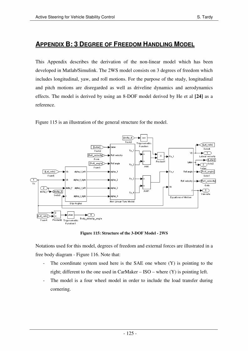
Active Steering for Vehicle Stability Control S. Tardy
- 125 -
APPENDIX B: 3 DEGREE OF FREEDOM HANDLING MODEL
This Appendix describes the derivation of the non-linear model which has been
developed in Matlab/Simulink. The 2WS model consists on 3 degrees of freedom which
includes longitudinal, yaw, and roll motions. For the purpose of the study, longitudinal
and pitch motions are disregarded as well as driveline dynamics and aerodynamics
effects. The model is derived by using an 8-DOF model derived by He et al [24] as a
reference.
Figure 115 is an illustration of the general structure for the model.
Figure 115: Structure of the 3-DOF Model - 2WS
Notations used for this model, degrees of freedom and external forces are illustrated in a
free body diagram - Figure 116. Note that:
- The coordinate system used here is the SAE one where (Y) is pointing to the
right; different to the one used in CarMaker – ISO – where (Y) is pointing left.
- The model is a four wheel model in order to include the load transfer during
cornering.
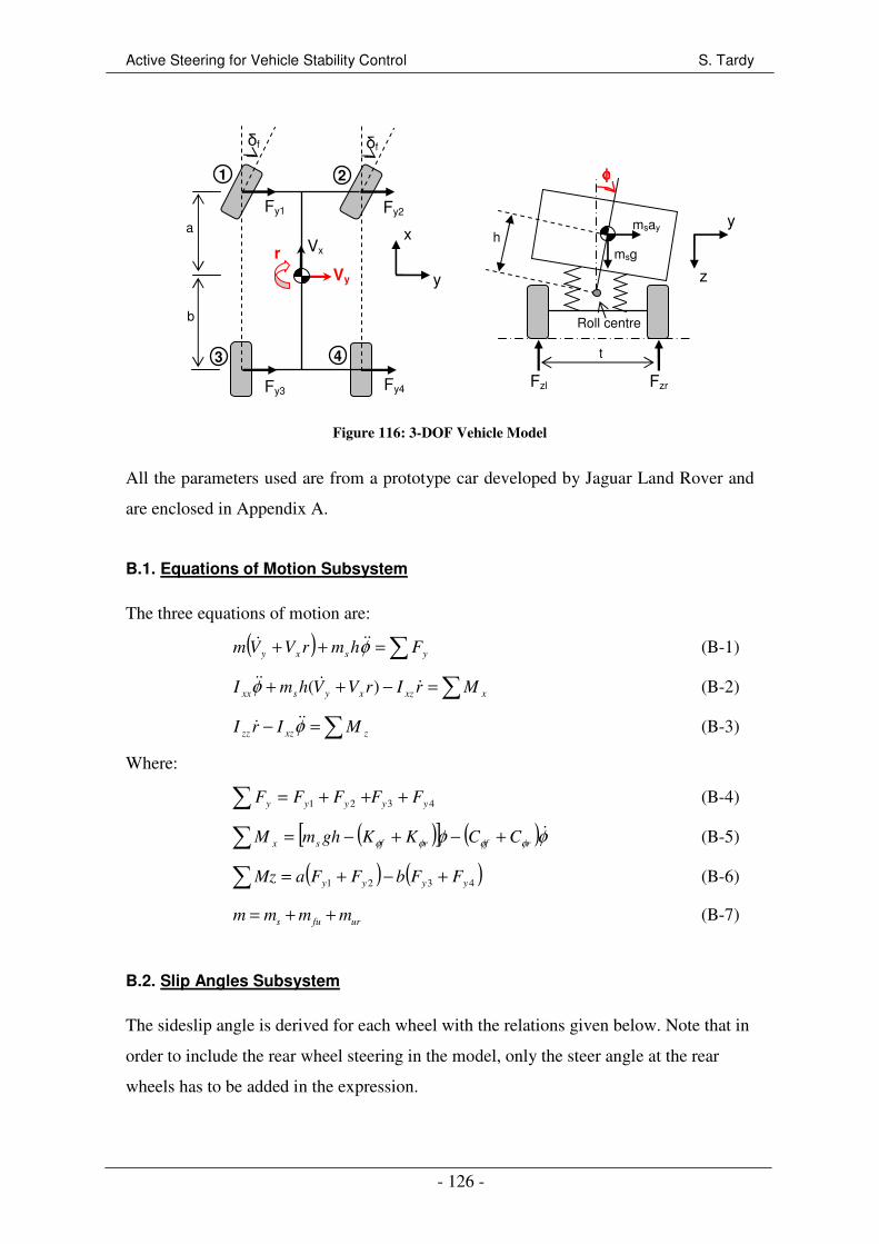
Active Steering for Vehicle Stability Control S. Tardy
- 126 -
Figure 116: 3-DOF Vehicle Model
All the parameters used are from a prototype car developed by Jaguar Land Rover and
are enclosed in Appendix A.
B.1. Equations of Motion Subsystem
The three equations of motion are:
( ) ∑=++ ysxy FhmrVVm φ&&& (B-1)
∑=−++ xxzxysxx MrIrVVhmI &&&& )(φ (B-2)
∑=− zxzzz MIrI φ&&& (B-3)
Where:
4321 yyyyy FFFFF +++=∑ (B-4)
( )[ ] ( )φφ φφφφ&
rfrfsx CCKKghmM +−+−=∑ (B-5)
( ) ( )∑ +−+= 4321 yyyy FFbFFaMz (B-6)
s fu urm m m m= + + (B-7)
B.2. Slip Angles Subsystem
The sideslip angle is derived for each wheel with the relations given below. Note that in
order to include the rear wheel steering in the model, only the steer angle at the rear
wheels has to be added in the expression.
a
b
Fy1
Roll centre
φφφφ
msay h
Fy3 Fy4
Fy2
Fzl Fzr
Vx
Vy
x
y
y
z r
δf δf
msg
t
1 2
3 4

Active Steering for Vehicle Stability Control S. Tardy
- 127 -
1
1 tan( / 2)
y
f
x
V ar
V r tα δ−
+ = −
+
&
& (B-8)
1
2 tan( / 2)
y
f
x
V ar
V r tα δ−
+ = −
−
&
& (B-9)
1
3 tan( / 2)
y
x
V br
V r tα −
− =
+
&
& (
rδ− ) only for 4WS vehicle model (B-10)
1
4 tan( / 2)
y
x
V br
V r tα −
− =
−
&
& (
rδ− ) only for 4WS vehicle model (B-11)
B.3 Non-linear Tyre Model Subsystem
B.3.1 Vertical Loads
The lateral load transfer is considered: vertical tyre load are derived from [24] as the
sum of the static tyre load and a load transfer due to the roll and lateral motions. The
equations are for each wheel:
( )1
1
2
y s rs f
z uf uf f f
a m l hmgbF m h K C
l t l tφ φφ φ
= + + + − −
& (B-12)
( )2
1
2
y s rs f
z uf uf f f
a m l hmgbF m h K C
l t l tφ φφ φ
= − + − − −
& (B-13)
( )3
1
2
y s fs r
z ur ur r r
a m l hmgaF m h K C
l t l tφ φφ φ
= + + + − −
& (B-14)
( )4
1
2
y s fs r
z ur ur r r
a m l hmgaF m h K C
l t l tφ φφ φ
= − + − − −
& (B-15)
B.3.1 Tyre Model
The non-linearity of the tyre must be taken into consideration since the lateral
acceleration could be important at high speed. An empirical tyre model developed by
Pacejka [35] is used. This model, commonly called “Magic Formula”, calculates the
lateral force as a function of the side slip angle and the vertical load on the tyre:
[ ]{ }( )sin arctan (1 )( ) arctan ( )y h h v
F D C B E S E B S Sα α= − + + + + (B-16)
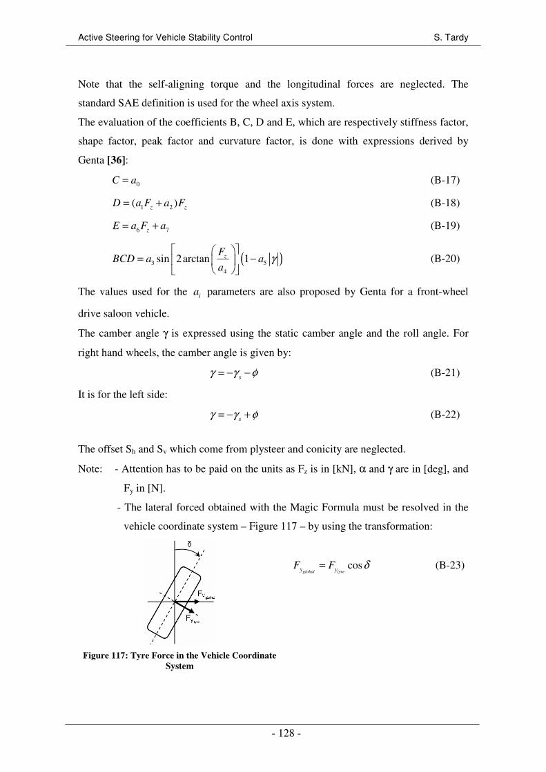
Active Steering for Vehicle Stability Control S. Tardy
- 128 -
Note that the self-aligning torque and the longitudinal forces are neglected. The
standard SAE definition is used for the wheel axis system.
The evaluation of the coefficients B, C, D and E, which are respectively stiffness factor,
shape factor, peak factor and curvature factor, is done with expressions derived by
Genta [36]:
0C a= (B-17)
1 2( )z z
D a F a F= + (B-18)
6 7zE a F a= + (B-19)
( )3 5
4
sin 2arctan 1zF
BCD a aa
γ
= −
(B-20)
The values used for the i
a parameters are also proposed by Genta for a front-wheel
drive saloon vehicle.
The camber angle γ is expressed using the static camber angle and the roll angle. For
right hand wheels, the camber angle is given by:
sγ γ φ= − − (B-21)
It is for the left side:
sγ γ φ= − + (B-22)
The offset Sh and Sv which come from plysteer and conicity are neglected.
Note: - Attention has to be paid on the units as Fz is in [kN], α and γ are in [deg], and
Fy in [N].
- The lateral forced obtained with the Magic Formula must be resolved in the
vehicle coordinate system – Figure 117 – by using the transformation:
Figure 117: Tyre Force in the Vehicle Coordinate
System
cosglobal tyrey y
F F δ= (B-23)
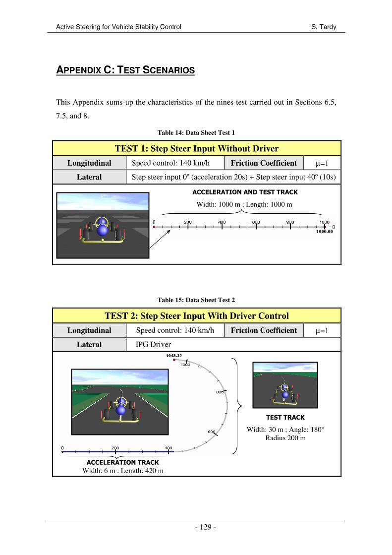
Active Steering for Vehicle Stability Control S. Tardy
- 129 -
APPENDIX C: TEST SCENARIOS
This Appendix sums-up the characteristics of the nines test carried out in Sections 6.5,
7.5, and 8.
Table 14: Data Sheet Test 1
TEST 1: Step Steer Input Without Driver
Longitudinal Speed control: 140 km/h Friction Coefficient µ=1
Lateral Step steer input 0º (acceleration 20s) + Step steer input 40º (10s)
Table 15: Data Sheet Test 2
TEST 2: Step Steer Input With Driver Control
Longitudinal Speed control: 140 km/h Friction Coefficient µ=1
Lateral IPG Driver
TEST TRACK
Width: 30 m ; Angle: 180°
Radius 200 m
ACCELERATION TRACK Width: 6 m ; Length: 420 m
ACCELERATION AND TEST TRACK
Width: 1000 m ; Length: 1000 m
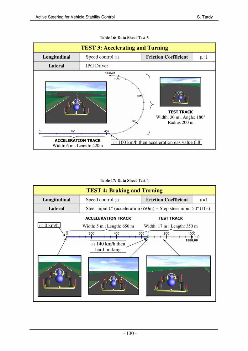
Active Steering for Vehicle Stability Control S. Tardy
- 130 -
Table 16: Data Sheet Test 3
TEST 3: Accelerating and Turning
Longitudinal Speed control (1) Friction Coefficient µ=1
Lateral IPG Driver
Table 17: Data Sheet Test 4
TEST 4: Braking and Turning
Longitudinal Speed control (1) Friction Coefficient µ=1
Lateral Steer input 0º (acceleration 650m) + Step steer input 50º (10s)
ACCELERATION TRACK
Width: 5 m ; Length: 650 m
TEST TRACK
Width: 17 m ; Length: 350 m
(1) 140 km/h then
hard braking
(1) 0 km/h
TEST TRACK Width: 30 m ; Angle: 180°
Radius 200 m
ACCELERATION TRACK Width: 6 m ; Length: 420m
(1) 100 km/h then acceleration gas value 0.8
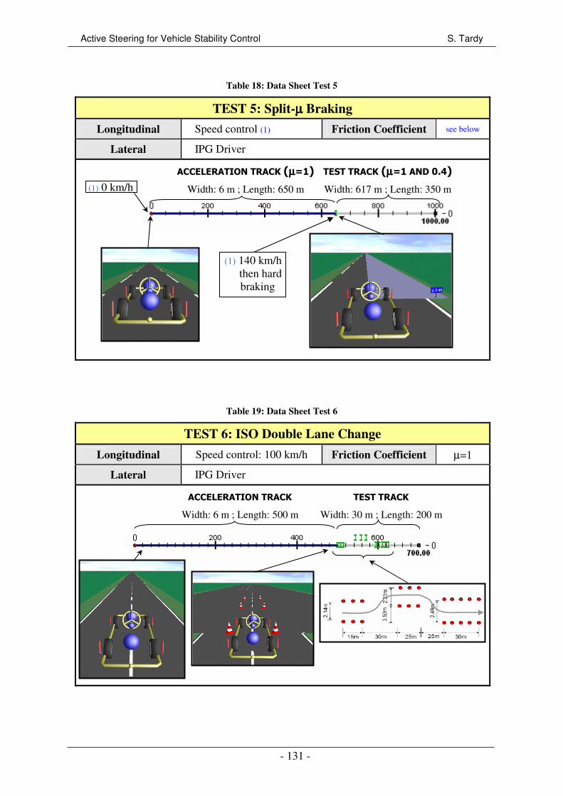
Active Steering for Vehicle Stability Control S. Tardy
- 131 -
Table 18: Data Sheet Test 5
TEST 5: Split-µµµµ Braking
Longitudinal Speed control (1) Friction Coefficient see below
Lateral IPG Driver
Table 19: Data Sheet Test 6
TEST 6: ISO Double Lane Change
Longitudinal Speed control: 100 km/h Friction Coefficient µ=1
Lateral IPG Driver
ACCELERATION TRACK
Width: 6 m ; Length: 500 m
TEST TRACK
Width: 30 m ; Length: 200 m
ACCELERATION TRACK (µµµµ=1)
Width: 6 m ; Length: 650 m
TEST TRACK (µµµµ=1 AND 0.4)
Width: 617 m ; Length: 350 m
(1) 140 km/h
then hard
braking
(1) 0 km/h
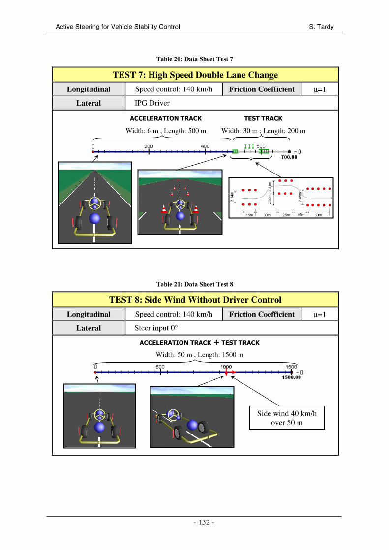
Active Steering for Vehicle Stability Control S. Tardy
- 132 -
Table 20: Data Sheet Test 7
TEST 7: High Speed Double Lane Change
Longitudinal Speed control: 140 km/h Friction Coefficient µ=1
Lateral IPG Driver
Table 21: Data Sheet Test 8
TEST 8: Side Wind Without Driver Control
Longitudinal Speed control: 140 km/h Friction Coefficient µ=1
Lateral Steer input 0°
Side wind 40 km/h
over 50 m
ACCELERATION TRACK
Width: 6 m ; Length: 500 m
TEST TRACK
Width: 30 m ; Length: 200 m
ACCELERATION TRACK + TEST TRACK
Width: 50 m ; Length: 1500 m
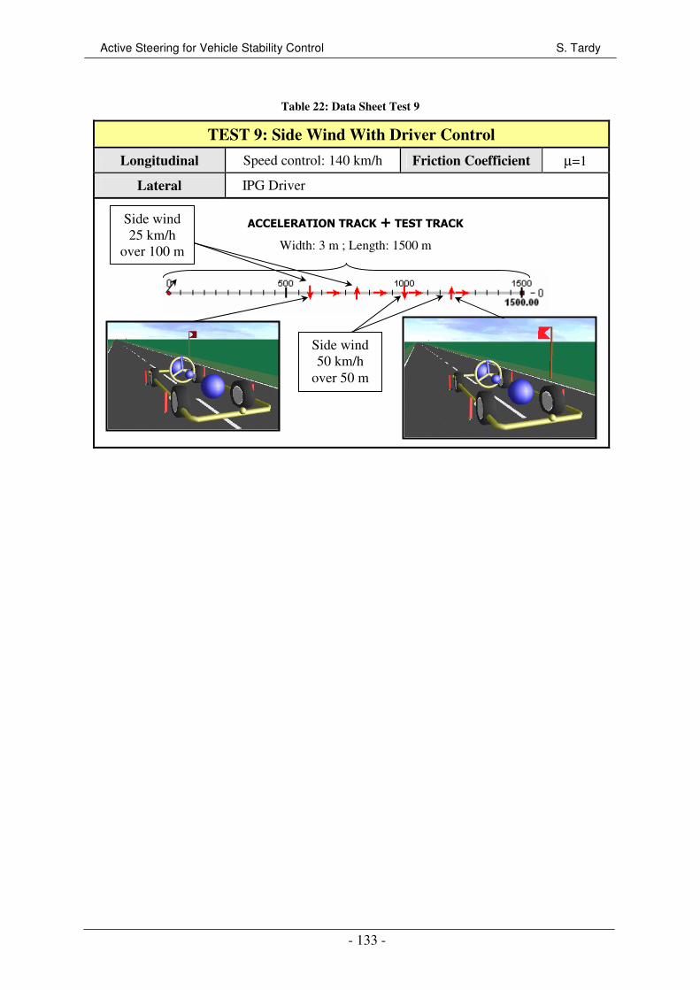
Active Steering for Vehicle Stability Control S. Tardy
- 133 -
Table 22: Data Sheet Test 9
TEST 9: Side Wind With Driver Control
Longitudinal Speed control: 140 km/h Friction Coefficient µ=1
Lateral IPG Driver
ACCELERATION TRACK + TEST TRACK
Width: 3 m ; Length: 1500 m
Side wind
25 km/h
over 100 m
Side wind
50 km/h
over 50 m