conex dia-g, dis-g - · pdf fileproduct features 3 conex® dia-g, dis-g 1 1. product...
TRANSCRIPT
GRUNDFOS DATA BOOKLET
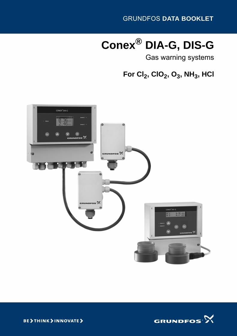
Conex® DIA-G, DIS-GGas warning systems
For Cl2, ClO2, O3, NH3, HCl

Ta
ble
of c
on
ten
ts
2
Conex® DIA-G, DIS-G
1. Product features 3Conex DIA-G gas warning systems 3Conex DIS-G gas warning systems 3
2. Identification 4Type key: Gas warning controllers 4Type key: Gas warning systems, prepacked 4
3. Technical data 5Conex DIA-G gas warning systems 5Conex DIS-G gas warning systems 6Amperometric gas sensors for chlorine, chlorine dioxide, ozone 7Potentiostatic gas sensors for chlorine, chlorine dioxide, ozone, ammonia, hydrochloric acid 8
4. Product selection 9Conex DIA-G gas warning systems 9Conex DIS-G gas warning systems 10Amperometric gas sensors for chlorine, chlorine dioxide, ozone 11Potentiostatic gas sensors for chlorine, chlorine dioxide, ozone, ammonia, hydrochloric acid 11
5. Accessories 12Cables for amperometric sensors 12Cables for potentiostatic sensors 12Interface adapter 12Sensor interface 12Battery backup, horn and flashlight 12AquaVision 12
6. Further product documentation 13WebCAPS 13WinCAPS 14

Pro
du
ct
fea
ture
s
Conex® DIA-G, DIS-G 1
1. Product features
Conex DIA-G gas warning systemsThe Conex DIA-G safety system monitors gas dosing installations and storage rooms.
Features
• Monitoring of two different storage rooms or two different gases at the same time.
• Simultaneous display of both measured values.
• Optimum safety thanks to permanent sensor monitoring, alarm relay and optional backup operation (uninterrupted power supply) by connection of an external buffer battery.
• Very short response time in case of a sudden change of the gas concentration.
• Long and maintenance-free sensor service life.
• Sensor recognition and auto-calibration as well as monitoring of sensor life.
• Separate sensor interface for one potentiostatic sensor. When using the separate sensor interface, Conex DIA-G can be installed in a control room at a distance of up to 500 m from the sensor interface.
• Connection of potentiostatic sensors via CAN-bus.
• Connection with AquaVision software or PLC via CAN-Bus.
• Optional audible and visual alarm device.
• Wide-range power supply unit 110-240 V - 10 %/+ 10 % (50/60 Hz) or 24 V DC.
• Display languages: German, English, French, Spanish, Polish and Russian.
Monitoring parameters
• Chlorine
• Chlorine dioxide
• Ozone
• Ammonia
• Hydrochloric acid.
Fig. 1 Conex DIA-G gas warning system with sensor interfaces and potentiostatic sensors
Conex DIS-G gas warning systemsThe Conex DIS-G safety system monitors gas dosing installations and storage rooms.
Features
• Monitoring of two gases at the same time
• Simultaneous display of both measured values
• Optimum safety thanks to the automatic sensor test function
• Very short response time in case of a sudden change of the gas concentration
• Long and maintenance-free sensor service life
• Optional audible and visual alarm device
• Display languages: German, English and French.
Monitoring parameters
• Chlorine
• Chlorine dioxide
• Ozone.
Fig. 2 Conex DIS-G gas warning system with amperometric sensors
TM
04
85
95
37
12
TM
04
85
94
37
12
3

Ide
ntific
atio
n
4
Conex® DIA-G, DIS-G2
2. Identification
Type key: Gas warning controllersExample: DIA-G, 1-D/A/HC 2-D/A/HC, W-J
Type key: Gas warning systems, prepackedExample: DIA-G-P, CLP-OP-B, W-J
Example: DIA-G 1-D/A/HC 2-D/A/HC W -J
Conex gas warning system
DIS-G Dosing Instrumentation Standard, with gas detection
DIA-G Dosing Instrumentation Advanced, with gas detection
Sensor 1
D Chlorine gas/chlorine dioxide gas/ozone gas
A Ammonia gas
HC Hydrochloric acid gas
Sensor 2
D Chlorine gas/chlorine dioxide gas/ozone gas
A Ammonia gas
HC Hydrochloric acid gas
X No sensor
Mounting
W Wall-mounting
Voltage
G 1 x 230-240 V, 50/60 Hz
H 1 x 115-120 V, 50/60 Hz
J 110-240 V, 50/60 Hz, 24 V DC
Example: DIA-G -P, CLP- OP- B, W -J
Conex gas warning system
DIS-G Dosing Instrumentation Standard, with gas detection
DIA-G Dosing Instrumentation Advanced, with gas detection
P Prepacked
Sensor 1
CCA Chlorine gas/chlorine dioxide gas, amperometric
OA Ozone gas, amperometric
CLP Chlorine gas, potentiostatic
CDP Chlorine dioxide gas, potentiostatic
OP Ozone gas, potentiostatic
AP Ammonia gas, potentiostatic
HCP Hydrochloric acid gas, potentiostatic
Sensor 2
CCA Chlorine gas/chlorine dioxide gas, amperometric
OA Ozone gas, amperometric
CLP Chlorine gas, potentiostatic
CDP Chlorine dioxide gas, potentiostatic
OP Ozone gas, potentiostatic
AP Ammonia gas, potentiostatic
HCP Hydrochloric acid gas, potentiostatic
X No sensor
Option
B Battery backup
X No battery backup
Mounting
W Wall-mounting
Voltage
G 1 x 230-240 V, 50/60 Hz
H 1 x 115-120 V, 50/60Hz
J 110-240 V, 50/60 Hz, 24 V DC

Te
ch
nic
al
da
ta
Conex® DIA-G, DIS-G 3
3. Technical data
Conex DIA-G gas warning systems
Fig. 3 Conex DIA-G
Technical data
Dimensions
Fig. 4 Conex DIA-G controller
Fig. 5 Sensor interface
TM
04
85
95
37
12
Electronics 16-bit microprocessor technology
Display Backlit plain-text display
Display languagesGerman, English, French, Spanish, Russian and Polish
Indication mode in ppm for measured values of both sensors
Relay outputs
Five potential-free relay outputs, per software switchable to NO (normally open) or NC (normally closed), fail-safe; max. 250 V/6 A, max. 550 VA• two relays for the limit values of each of both
sensors• one alarm relay; free assignment to the limit
values or to sensor test.
Signal inputs
• two measured value inputs (for amperometric sensors 1 and 2)
• internal CAN bus, including connections for two interfaces, each for the operation of one potentiostatic sensor.
Signal outputs
• two (0)4-20 mA outputs, max. load 500 Ohm, with wire breakage monitoring; free assignment to the measuring range of the sensors.
• external CAN bus interface.
Safety functions
• permanent sensor monitoring or automatic sensor test, interval between tests adjustable from every 0.5 to 30 days
• wire breakage monitoring of all current outputs
• optional backup battery with backup indication on the display, allowing Conex DIA-G to work for at least one hour after mains failure
• automatic adjustment of data specific to the sensor (for example calibration data)
• display of the sensor exchange intervals with a plain-text message.
Permissible temperature [°C]
Conex DIA-G and sensor interface (without sensor):Operation: 0 to +50Storage: -20 to +65
Permissible relative humidity [%]
Max. 90 (non-condensing)
Power supply110-240 V - 10 %/+ 10 % (50/60 Hz), or 24 VDC
Power consumption [VA]
Approx. 20
Material (enclosure) ABS, resistant to chemicals
Enclosure classConex DIA-G enclosure and sensor interface: IP65
Weight [kg] Approx. 1.5
TM
04
18
46
11
08
TM
04
18
47
11
08
59
125
84
59.5
184.
5
212
198
10
145
27 99
Ø 4.5
101.5
80
4212
0
146.
5
5

Te
ch
nic
al d
ata
6
Conex® DIA-G, DIS-G3
Conex DIS-G gas warning systems
Fig. 6 Conex DIS-G
Technical data
Dimensions
Fig. 7 Conex DIS-G controller
TM
04
85
94
37
12
Electronics I2C bus technology
Accuracy [%] ± 1
Display LCD, 2 lines, 2 x 16 characters
Display languages English, German, French
Indication mode in ppm for measured values of both sensors
Relay outputs
Five potential-free relay outputs; max. 250 V/6 A, max. 550 VA ohmic load• two relays for the limit values of each of both
sensors• one alarm relay; free assignment to the limit
values or to sensor test
Signal inputs Two measured value inputs (sensors 1 and 2)
Signal outputsTwo analog outputs, (0) 4-20 mA, max. load 400 Ohm, assigned to the 0-5 ppm range
Sensor testInterval between automatic sensor tests adjustable from every 0.5 to 14 days
Permissible temperature [°C]
Operation: 0 to +45Storage: -20 to +65
Permissible relative air humidity [%]
Max. 90 (non-condensing)
Power supply230/240 V -1 0 %/+ 10 % (50/60 Hz), or 115/120 V - 10 %/+ 10 % (50/60 Hz)
Power consumption [VA]
approx. 5
Material (enclosure) ABS, resistant to chemicals
Enclosure class IP65
Weight [kg] Approx. 0.8
TM
04
18
48
11
08
72.5 131.3
165.5
1517.25
13.5
120
15
59
92.3
55.5
160.
5
105

Te
ch
nic
al
da
ta
Conex® DIA-G, DIS-G 3
Amperometric gas sensors for chlorine, chlorine dioxide, ozone
Features
• Rugged, low-budget gas sensors.
• Monitoring of chlorine, chlorine dioxide or ozone in the air of dry rooms.
• Complete with wall installation kit.
Fig. 8 Amperometric sensor
Dimensions
Fig. 9 Amperometric sensor
Technical dataT
M0
4 2
22
6 2
10
8
TM
04
20
19
18
08
52
55Ø 68
Measured parameter Chlorine and chlorine dioxide Ozone
Measuring range [ppm] 0.00 - 5.00 0.00 - 5.00
Accuracy [%] ± 10 ± 10
Response time t90 [s] 2 (at 20 °C) 2 (at 20 °C)
Recovery time [min] 10-15 10-15
Expected life [months] 12 12
Permissible operating temperature [°C] 5-45 5-45
Permissible storage temperature [°C] 5-30 5-30
Permissible relative humidity (non-condensing) [%] max. 90 at 40 °C max. 90 at 40 °C
Installation wall-mounting wall-mounting
Max. distance between sensor and measuring amplifier [m] 100 100
Max. storage time [months] 9 9
Weight [g] 260 260
7

Te
ch
nic
al d
ata
8
Conex® DIA-G, DIS-G3
Potentiostatic gas sensors for chlorine, chlorine dioxide, ozone, ammonia, hydrochloric acid
Features
• Membrane-covered gas sensors with integrated RAM for challenging measuring tasks. Sensor type, production number, manufacturing date and slope are stored in the memory.
• Monitoring of chlorine, chlorine dioxide, ozone, ammonia, and hydrochloric acid in the air of dry rooms.
• Sensor recognition, auto-calibration, and monitoring of sensor life.
• A sensor is plugged directly into a sensor interface.
Fig. 10 Sensor interface
Fig. 11 Potentiostatic sensor
Dimensions
Fig. 12 Potentiostatic sensor
Technical data
TM
04
85
96
37
12
TM
04
22
28
21
08
TM
04
22
29
21
08
23
Ø 15.6
Measured parameter Chlorine Chlorine dioxide Ozone Ammonia Hydrochloric acid
Measuring range [ppm] 0.00 - 20.00 0.00 - 1.00 0.00 - 1.00 0 - 100 0.0 - 30.0
Resolution (at 20 °C) [ppm] < 0.05 < 0.03 < 0.02 < 1 < 0.7
Linearity (of full scale) [%] < 5 < 10 < 10 < 10 < 5
Sensitivity drift [%] < 10 per 6 months < 10 per 6 months < 10 per 6 months < 5 per 6 months < 3 per 6 months
Response time, t90 (at 20 °C) [s] < 30 < 120 < 60 < 60 < 70
Recovery time [min] 1 1 1 1 1
Expected life [months] 24 24 18 24 24
Permissible operating temperature [°C] -20 to +40 -20 to +40 -20 to +40 -20 to +40 -20 to +40
Storage temperature [°C] +4 to +10 +4 to +10 +4 to +10 +4 to +10 +4 to +10
Max. storage time [months] 3 3 3 3 3
Weight [g] 150 150 150 150 150
Max. distance to Conex DIA-G (bus line length) [m]
500 500 500 500 500
Permissible relative humidity (non-condensing) [%]
max. 90 at 40 °C max. 90 at 40 °C max. 90 at 40 °C max. 90 at 40 °C max. 90 at 40 °C

Pro
du
ct
se
lec
tio
n
Conex® DIA-G, DIS-G 4
4. Product selection
Conex DIA-G gas warning systems
Co
ntr
oll
er
Co
ne
x
Pre
pa
ck
ed
(w
ith
se
ns
ors
)
Sensor 1 Sensor 2 Voltage
Type designation Product number
Ch
lori
ne
ga
s/c
hlo
rin
e d
iox
ide
, a
mp
ero
me
tric
Ozo
ne
ga
s,
am
pe
rom
etr
ic
Ch
lori
ne
, p
ote
nti
os
tati
c
Ch
lori
ne
dio
xid
e,
po
ten
tio
sta
tic
Ozo
ne
, p
ote
nti
os
tati
c
Am
mo
nia
, p
ote
nti
os
tati
c
Hy
dro
ch
lori
c a
cid
, p
ote
nti
os
tati
c
Ch
lori
ne
ga
s/c
hlo
rin
e d
iox
ide
, a
mp
ero
me
tric
Ozo
ne
ga
s,
am
pe
rom
etr
ic
Ch
lori
ne
, p
ote
nti
os
tati
c
Ch
lori
ne
dio
xid
e,
po
ten
tio
sta
tic
Ozo
ne
, p
ote
nti
os
tati
c
Am
mo
nia
, p
ote
nti
os
tati
c
Hy
dro
ch
lori
c a
cid
, p
ote
nti
os
tati
c
No
se
ns
or
Ba
tte
ry b
ac
ku
p
11
0-2
40
V,
50
/60
Hz,
24
V
23
0 V
, 5
0/6
0 H
z
11
5 V
, 5
0/6
0 H
z
DIA-G
● DIA-G. 1-D/A/HC 2-D/A/HC. W-J 96732266
● ● ● ● DIA-G-P. CCA-X-X. W-J 95700081
● ● ● ● DIA-G-P. CCA-CCA-X. W-J 96735209
● ● ● ● ● DIA-G-P. CCA-X-B. W-J 95700964
● ● ● ● ● DIA-G-P. CCA-CCA-B. W-J 95700965
● ● ● ● DIA-G-P. OA-X-X. W-J 95700966
● ● ● ● DIA-G-P. OA-OA-X. W-J 95700967
● ● ● ● ● DIA-G-P. OA-OA-B. W-J 95700968
● ● ● ● DIA-G-P. CLP-X-X. W-J 95700080
● ● ● ● DIA-G-P. CLP-CLP-X. W-J 95700483
● ● ● ● ● DIA-G-P. CLP-CLP-B. W-J 95700969
● ● ● ● DIA-G-P. CLP-CDP-X. W-J 95700970
● ● ● ● ● DIA-G-P. CLP-CDP-B. W-J 95700971
● ● ● ● DIA-G-P. CLP-AP-X. W-J 95700972
● ● ● ● ● DIA-G-P. CLP-AP-B. W-J 95700973
● ● ● ● DIA-G-P. CDP-X-X. W-J 95700854
● ● ● ● ● DIA-G-P. CDP-X-B. W-J 95700976
● ● ● ● DIA-G-P. CDP-CDP-X. W-J 95700977
● ● ● ● ● DIA-G-P. CDP-CDP-B. W-J 95700978
● ● ● ● DIA-G-P. CDP-HCP-X. W-J 95700979
● ● ● ● ● DIA-G-P. CDP-HCP-B. W-J 95700980
● ● ● ● DIA-G-P. OP-X-X. W-J 95700981
● ● ● ● DIA-G-P. OP-OP-X. W-J 95700982
● ● ● ● ● DIA-G-P. OP-OP-B. W-J 95700983
● ● ● ● DIA-G-P. AP-X-X. W-J 96697849
● ● ● ● ● DIA-G-P. AP-X-B. W-J 95700974
● ● ● ● DIA-G-P. AP-AP-X. W-J 96725667
● ● ● ● ● DIA-G-P. AP-AP-B. W-J 95700975
● ● ● ● DIA-G-P. HCP-X-X. W-J 95700984
● ● ● ● ● DIA-G-P. HCP-X-B. W-J 95700985
● ● ● ● DIA-G-P. HCP-HCP-X. W-J 95700986
● ● ● ● ● DIA-G-P. HCP-HCP-B. W-J 95700987
9

Pro
du
ct s
ele
ctio
n
10
Conex® DIA-G, DIS-G4
Conex DIS-G gas warning systemsC
on
tro
lle
r
Pre
pa
ck
ed
(w
ith
se
ns
ors
)Sensor 1 Sensor 2 Voltage
Type designation Product number
Ch
lori
ne
ga
s/c
hlo
rin
e d
iox
ide
, a
mp
ero
me
tric
Ozo
ne
ga
s,
am
pe
rom
etr
ic
Ch
lori
ne
, p
ote
nti
os
tati
c
Ch
lori
ne
dio
xid
e,
po
ten
tio
sta
tic
Ozo
ne
, p
ote
nti
os
tati
c
Am
mo
nia
, p
ote
nti
os
tati
c
Hy
dro
ch
lori
c a
cid
, p
ote
nti
os
tati
c
Ch
lori
ne
ga
s/c
hlo
rin
e d
iox
ide
, a
mp
ero
me
tric
Ozo
ne
ga
s,
am
pe
rom
etr
ic
Ch
lori
ne
, p
ote
nti
os
tati
c
Ch
lori
ne
dio
xid
e,
po
ten
tio
sta
tic
Ozo
ne
, p
ote
nti
os
tati
c
Am
mo
nia
, p
ote
nti
os
tati
c
Hy
dro
ch
lori
c a
cid
, p
ote
nti
os
tati
c
No
se
ns
or
Ba
tte
ry b
ac
ku
p
11
0-2
40
V,
50
/60
Hz,
24
V
23
0 V
, 5
0/6
0 H
z
11
5 V
, 5
0/6
0 H
z
DIS-G
● DIS-G. 1-D 2-D. W-G 96736238
● DIS-G. 1-D 2-D. W-H 95701378
● ● ● ● DIS-G-P. CCA-X-X. W-G 96703835
● ● ● ● DIS-G-P. CCA-X-X. W-H 95701170
● ● ● ● DIS-G-P. CCA-CCA-X. W-G 96734178
● ● ● ● DIS-G-P. CCA-CCA-X. W-H 95706182
● ● ● ● DIS-G-P. OA-X-X. W-G 95700018
● ● ● ● DIS-G-P. OA-X-X. W-H 95706183
● ● ● ● DIS-G-P. OA-OA-X. W-G 95701231
● ● ● ● DIS-G-P. OA-OA-X. W-H 95706184

Pro
du
ct
se
lec
tio
n
Conex® DIA-G, DIS-G 4
Amperometric gas sensors for chlorine, chlorine dioxide, ozone
Potentiostatic gas sensors for chlorine, chlorine dioxide, ozone, ammonia, hydrochloric acid
Description Product No
Amperometric gas sensor for chlorine and chlorine dioxide, complete with installation set
91835237
Amperometric gas sensor for ozone, complete with installation set
96687714
Spare sensor disc for chlorine and chlorine dioxide 91835823
Spare sensor disc for ozone 96688728
Description Product No
Potentiostatic gas sensor for chlorine, without sensor interface
96732268
Potentiostatic gas sensor for chlorine, with sensor interface
95700843
Potentiostatic gas sensor for chlorine dioxide, without sensor interface
95700837
Potentiostatic gas sensor for chlorine dioxide, with sensor interface
95700844
Potentiostatic gas sensor for ozone, without sensor interface
95700838
Potentiostatic gas sensor for ozone, with sensor interface
95700845
Potentiostatic gas sensor for ammonia, without sensor interface
95700839
Potentiostatic gas sensor for ammonia, with sensor interface
95700846
Potentiostatic gas sensor for hydrochloric acid, without sensor interface
95700840
Potentiostatic gas sensor for hydrochloric acid, with sensor interface
95700842
11

Ac
ce
ss
orie
s
12
Conex® DIA-G, DIS-G5
5. Accessories
Cables for amperometric sensors
Cables for potentiostatic sensors
Interface adapter
Sensor interface
Battery backup, horn and flashlight
AquaVisionAquaVision is a bidirectional visualisation software for up to four Conex DIA-G controllers. The software allows also large systems to be monitored and controlled centrally.
For more information, please see the separate data booklet "Measurement and control accessories".
Description Product No
2-wire cable with screening
1 metre 96687719
2 metres 96725671
10 metres 96725670
20 metres 96725672
50 metres 96725673
Description Product No
4-wire cable with screening for CAN connection with sensor interface
10 metres 96725684
20 metres 96725685
50 metres 96725686
Description Product No
CAN bus/RS232 interface adaptor for connection of Conex DIA-G to a PLC or to the AquaVision software
95702009
Description Product No
A potentiostatic sensor is plugged directly into the sensor interface. Conex DIA-G can be installed in a control room at a distance of up to 500 m from the sensor interface.For simultaneous measurement of two values, please order two sensor interface units.
96725668
Designation Description Product No
Battery backup
Integrated battery charging unit with I/U charging characteristic, battery management with microcontroller, temperature regulation of charging voltage by sensor module, input voltage of the battery controller 115/230 V (50/60 Hz), input current, 0.84 A/115 V to 0.42 A/230 V, max. switch-on current, 2 A/2 ms, maintenance-free lead-acid battery, 24 V/7 Ah, buffer time for operation with two sensor interfaces > 1 h
96725709
Horn in grey ABS enclosure, IP55
230 V (50/60 Hz), nominal current, 100 mA 96696421
115 V (50/60 Hz), nominal current, 200 mA 96726994
Red flashlight in grey ABS enclosure, IP54, for outdoor and indoor installation
230 V (50/60 Hz), nominal current, 50 mA 96694063
115 V (50/60 Hz), nominal current, 60 mA 96726995

Fu
rth
er
pro
du
ct
do
cu
me
nta
tio
n
Conex® DIA-G, DIS-G 6
6. Further product documentation
WebCAPSWebCAPS is a Web-based Computer Aided Product Selection program available on www.grundfos.com.
WebCAPS contains detailed information on more than 220,000 Grundfos products in more than 30 languages.
Information in WebCAPS is divided into six sections:
• Catalogue
• Literature
• Service
• Sizing
• Replacement
• CAD drawings.
Catalogue
Based on fields of application and pump types, this section contains the following:• technical data• curves (QH, Eta, P1, P2, etc.) which can be adapted to the
density and viscosity of the pumped liquid and show the number of pumps in operation
• product photos• dimensional drawings• wiring diagrams• quotation texts, etc.
Literature
This section contains all the latest documents of a given pump, such as• data booklets• installation and operating instructions• service documentation, such as Service kit catalogue and
Service kit instructions• quick guides• product brochures.
Service
This section contains an easy-to-use interactive service catalogue. Here you can find and identify service parts of both existing and discontinued Grundfos pumps.Furthermore, the section contains service videos showing you how to replace service parts.
13

Fu
rthe
r pro
du
ct d
oc
um
en
tatio
n
14
Conex® DIA-G, DIS-G6
WinCAPS
Fig. 13 WinCAPS DVD
WinCAPS is a Windows-based Computer Aided Product Selection program containing detailed information on more than 220,000 Grundfos products in more than 30 languages.
The program contains the same features and functions as WebCAPS, but is an ideal solution if no internet connection is available.
WinCAPS is available on DVD and updated once a year.
Sizing
This section is based on different fields of application and installation examples and gives easy step-by-step instructions in how to size a product:• Select the most suitable and efficient pump for your
installation.• Carry out advanced calculations based on energy,
consumption, payback periods, load profiles, life cycle costs, etc.
• Analyse your selected pump via the built-in life cycle cost tool.• Determine the flow velocity in wastewater applications, etc.
Replacement
In this section you find a guide to selecting and comparing replacement data of an installed pump in order to replace the pump with a more efficient Grundfos pump. The section contains replacement data of a wide range of pumps produced by other manufacturers than Grundfos.
Based on an easy step-by-step guide, you can compare Grundfos pumps with the one you have installed on your site. When you have specified the installed pump, the guide will suggest a number of Grundfos pumps which can improve both comfort and efficiency.
CAD drawings
In this section, it is possible to download 2-dimensional (2D) and 3-dimensional (3D) CAD drawings of most Grundfos pumps.
These formats are available in WebCAPS:
2-dimensional drawings:• .dxf, wireframe drawings• .dwg, wireframe drawings.
3-dimensional drawings:• .dwg, wireframe drawings (without surfaces)• .stp, solid drawings (with surfaces)• .eprt, E-drawings.
0 1
Subject to alterations.

15

GRUNDFOS A/S . DK-8850 Bjerringbro . DenmarkTelephone: +45 87 50 14 00www.grundfos.com
The name Grundfos, the Grundfos logo, and the payoff be think innovate are registered trademarks owned by Grundfos Holding A/S or Grundfos A/S, Denmark. All rights reserved worldwide.
Being responsible is our foundationThinking ahead makes it possible
Innovation is the essence
96812342 0912
ECM: 1100245