conet mobile lab 3 - agh university of science and...
TRANSCRIPT
CoNeT Mobile Lab 3 PROFINET ON PHOENIX CONTACT PLATFORM
- PROFINET basics – Revision 1.0
University of Applied Sciences Duesseldorf
Process Informatics Laboratory (Pi-LAB)
http://www.pi-lab.de
Contact: [email protected]
Co-operative Network Training

2
CoNeT Mobile Box 3 – PROFINET on PC WORX
3
CoNeT Mobile Box 3 – PROFINET on PC WORX
Contents
PROFINET BASICS ................................................................................................................ 5
What is PROFINET? ............................................................................................................................................ 5
Function classes of PROFINET ........................................................................................................................... 5
COMMUNICATION AND SECURITY ................................................................................ 7
PROFINET Communication Concept ................................................................................................................ 7
PROFINET Security Concept .............................................................................................................................. 7
Questions ................................................................................................................................................................ 8
PROFINET VS. PROFIBUS ................................................................................................. 10
Advantages of PROFINET ................................................................................................................................. 10
Comparison PROFIBUS with PROFINET ...................................................................................................... 11
Integration with PROFIBUS .............................................................................................................................. 11
Questions .............................................................................................................................................................. 12
ISO/OSI REFERENCE MODEL ......................................................................................... 13
Communication Path .......................................................................................................................................... 15
Questions .............................................................................................................................................................. 16
ETHERNET BASICS ............................................................................................................ 17
Short History ....................................................................................................................................................... 17
Access Method ..................................................................................................................................................... 18
Standard Ethernet Frames ................................................................................................................................. 19 What are frames? .............................................................................................................................................. 19
MAC Address ...................................................................................................................................................... 20
Network Topologies ............................................................................................................................................ 20
Some Network Components ............................................................................................................................... 21 Switches ........................................................................................................................................................... 21 Hubs ................................................................................................................................................................. 22 Routers ............................................................................................................................................................. 23 Signal Coding ................................................................................................................................................... 23 VLAN ............................................................................................................................................................... 23
4
CoNeT Mobile Box 3 – PROFINET on PC WORX
Questions .............................................................................................................................................................. 24
PROFINET CABLING AND CABLE-JACK SYSTEMS ................................................. 25
Network Installation ........................................................................................................................................... 25
Cables ................................................................................................................................................................... 26 Twisted pair cables (from copper):................................................................................................................... 26 Fiber optic cables ............................................................................................................................................. 26 Hybrid cables ................................................................................................................................................... 27
Connectors ........................................................................................................................................................... 27 Connectors for copper-based cables ................................................................................................................. 27 Connectors for fiber optic cables ...................................................................................................................... 28
Wireless system ................................................................................................................................................... 28
Questions .............................................................................................................................................................. 29
INTERNET PROTOCOL FAMILY .................................................................................... 30
Internet Protocol (IP) .......................................................................................................................................... 30
Subnet Mask ........................................................................................................................................................ 31
User Datagram Protocol (UDP) ......................................................................................................................... 31
Transmission Control Protocol (TCP) .............................................................................................................. 31
Port Number Assignment ................................................................................................................................... 32
Address Resolution Protocol (ARP) and Reverse Address Resolution Protocol (RARP) ............................. 32
Other useful protocols ........................................................................................................................................ 33
Questions .............................................................................................................................................................. 33
SUMMARY ............................................................................................................................. 34
5
CoNeT Mobile Box 3 – PROFINET on PC WORX
PROFINET Basics
What is PROFINET?
If we talk about industrial automation, you might think about fieldbus systems first, such as
PROFIBUS, INTERBUS, DeviceNet or CANopen, etc. Indeed, the widespread usage of
fieldbus technology has become established in industrial automation in the past few years.
One of the important advantages of fieldbus systems is that you can migrate from your central
automation systems to the decentralized ones.
If we talk about communication between computers, you may be familiar with intensive data-
transferring networks such as Internet. The development of this kind of communication
transfer systems has increased rapidly. Most Internet communications are based on the
Ethernet standard that was given by IEEE 802.3 (Institute of Electrical and Electronics
Engineers). One of the significant properties of the Ethernet is its simple structure. It can be
implemented easily and therefore is very popular.
PROFINET is the open and innovative standard
for industrial automation based on the industrial
Ethernet, i.e. you can exchange process data with
your machines as before but instead of using a
fieldbus system, you use the Ethernet as the medium
of communication.
The concept of the PROFINET satisfies all the requirements for industrial automation
technology. You can use PROFINET for your factory and process automations that require
response time under 100 milliseconds. Other applications, like drive technology applications
or clock-synchronized Motion Control, can be served with response time up to less than 1
millisecond. For the purpose of running safety applications, you can use PROFIsafe, which is
part of PROFINET.
PROFINET technology is developed and published by PROFIBUS/PROFINET International
e.V. (PI). It supplements the approved PROFIBUS technology, especially in terms of speed of
data transmission and the use of Information Technology (IT). PROFINET uses IT standards
such as TCP/IP and XML to communicate, configure and diagnose the machines or field
devices.
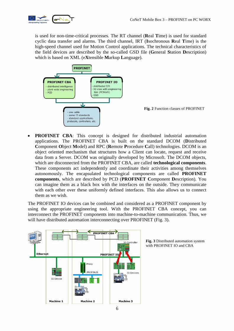
Function classes of PROFINET
In PROFINET, we can distinguish two function classes that are independent of each other, the
PROFINET IO and the PROFINET CBA (Component Based Automation). PROFINET IO is
concerned with distributed I/O (Input/Output) and PROFINET CBA is concerned with
distributed automation. Fig. 2 illustrates the function classes.
PROFINET IO: The distributed field devices are connected through the PROFINET
IO. If you are familiar with PROFIBUS, you will find considerable similarity between
these two systems; for example, process data from the field devices is transmitted into the
control system periodically.
PROFINET IO uses three different communication channels to exchange data with the
control systems and other devices. The standard TCP/IP channel is used for
parameterization, configuration and acyclic read/write operations. NRT (Non-Real Time)
Fig.1 PROFINET logo
6
CoNeT Mobile Box 3 – PROFINET on PC WORX
is used for non-time-critical processes. The RT channel (Real Time) is used for standard
cyclic data transfer and alarms. The third channel, IRT (Isochronous Real Time) is the
high-speed channel used for Motion Control applications. The technical characteristics of
the field devices are described by the so-called GSD file (General Station Description)
which is based on XML (eXtensible Markup Language).
Fig. 2 Function classes of PROFINET
PROFINET CBA: This concept is designed for distributed industrial automation
applications. The PROFINET CBA is built on the standard DCOM (Distributed
Component Object Model) and RPC (Remote Procedure Call) technologies. DCOM is an
object oriented mechanism that structures how a Client can locate, request and receive
data from a Server. DCOM was originally developed by Microsoft. The DCOM objects,
which are disconnected from the PROFINET CBA, are called technological components.
These components act independently and coordinate their activities among themselves
autonomously. The encapsulated technological components are called PROFINET
components, which are described by PCD (PROFINET Component Description). You
can imagine them as a black box with the interfaces on the outside. They communicate
with each other over these uniformly defined interfaces. This also allows us to connect
them as we wish.
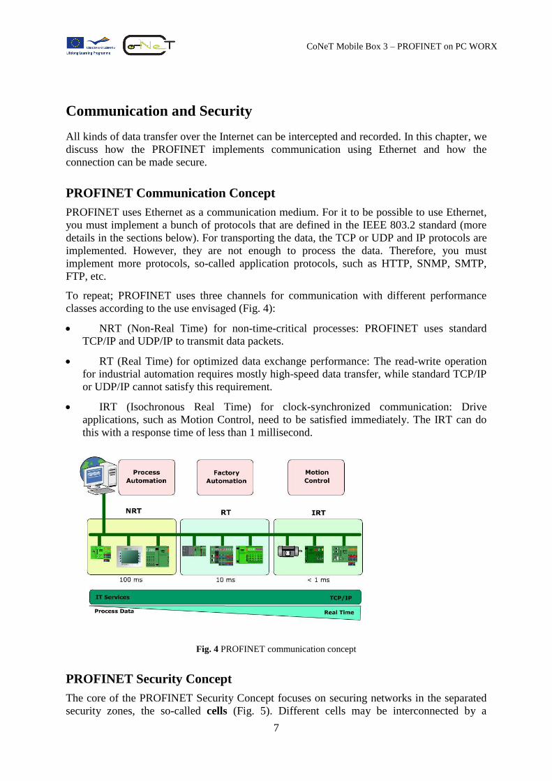
The PROFINET IO devices can be combined and considered as a PROFINET component by
using the appropriate engineering tool. With the PROFINET CBA concept, you can
interconnect the PROFINET components into machine-to-machine communication. Thus, we
will have distributed automation interconnecting over PROFINET (Fig. 3).
Fig. 3 Distributed automation system
with PROFINET IO and CBA
7
CoNeT Mobile Box 3 – PROFINET on PC WORX
Communication and Security
All kinds of data transfer over the Internet can be intercepted and recorded. In this chapter, we
discuss how the PROFINET implements communication using Ethernet and how the
connection can be made secure.
PROFINET Communication Concept
PROFINET uses Ethernet as a communication medium. For it to be possible to use Ethernet,
you must implement a bunch of protocols that are defined in the IEEE 803.2 standard (more
details in the sections below). For transporting the data, the TCP or UDP and IP protocols are
implemented. However, they are not enough to process the data. Therefore, you must
implement more protocols, so-called application protocols, such as HTTP, SNMP, SMTP,
FTP, etc.
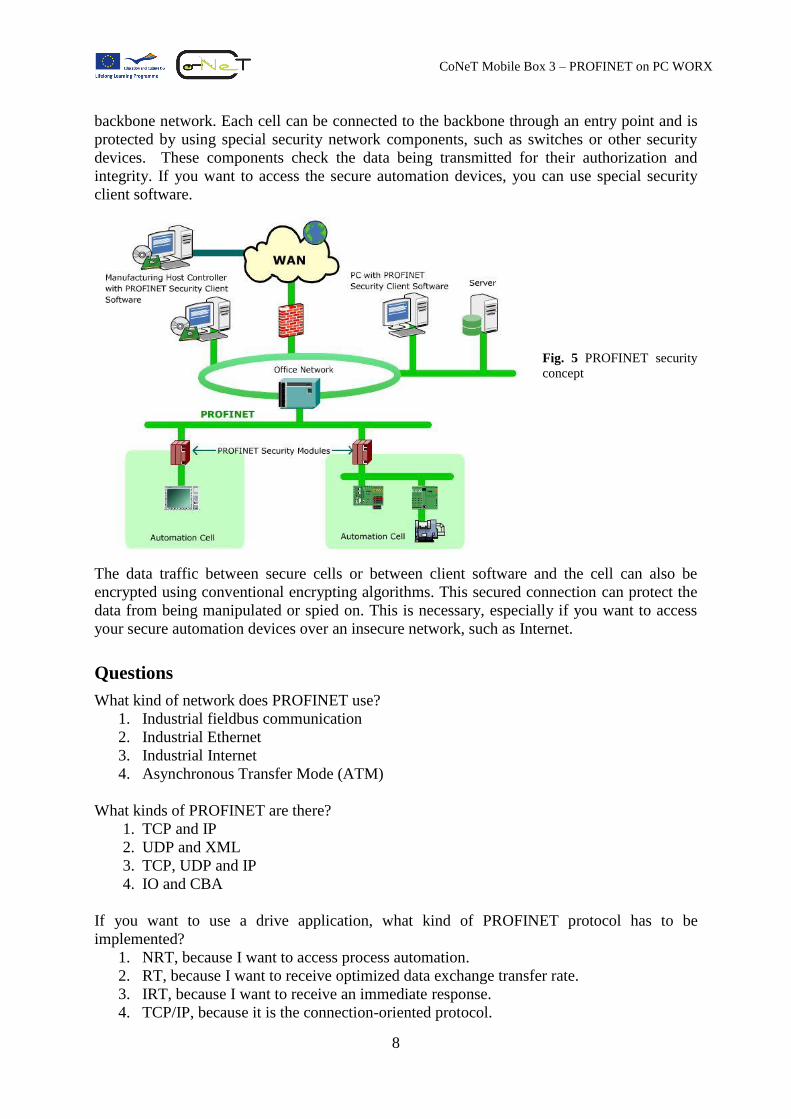
To repeat; PROFINET uses three channels for communication with different performance
classes according to the use envisaged (Fig. 4):
NRT (Non-Real Time) for non-time-critical processes: PROFINET uses standard
TCP/IP and UDP/IP to transmit data packets.
RT (Real Time) for optimized data exchange performance: The read-write operation
for industrial automation requires mostly high-speed data transfer, while standard TCP/IP
or UDP/IP cannot satisfy this requirement.
IRT (Isochronous Real Time) for clock-synchronized communication: Drive
applications, such as Motion Control, need to be satisfied immediately. The IRT can do
this with a response time of less than 1 millisecond.
Fig. 4 PROFINET communication concept
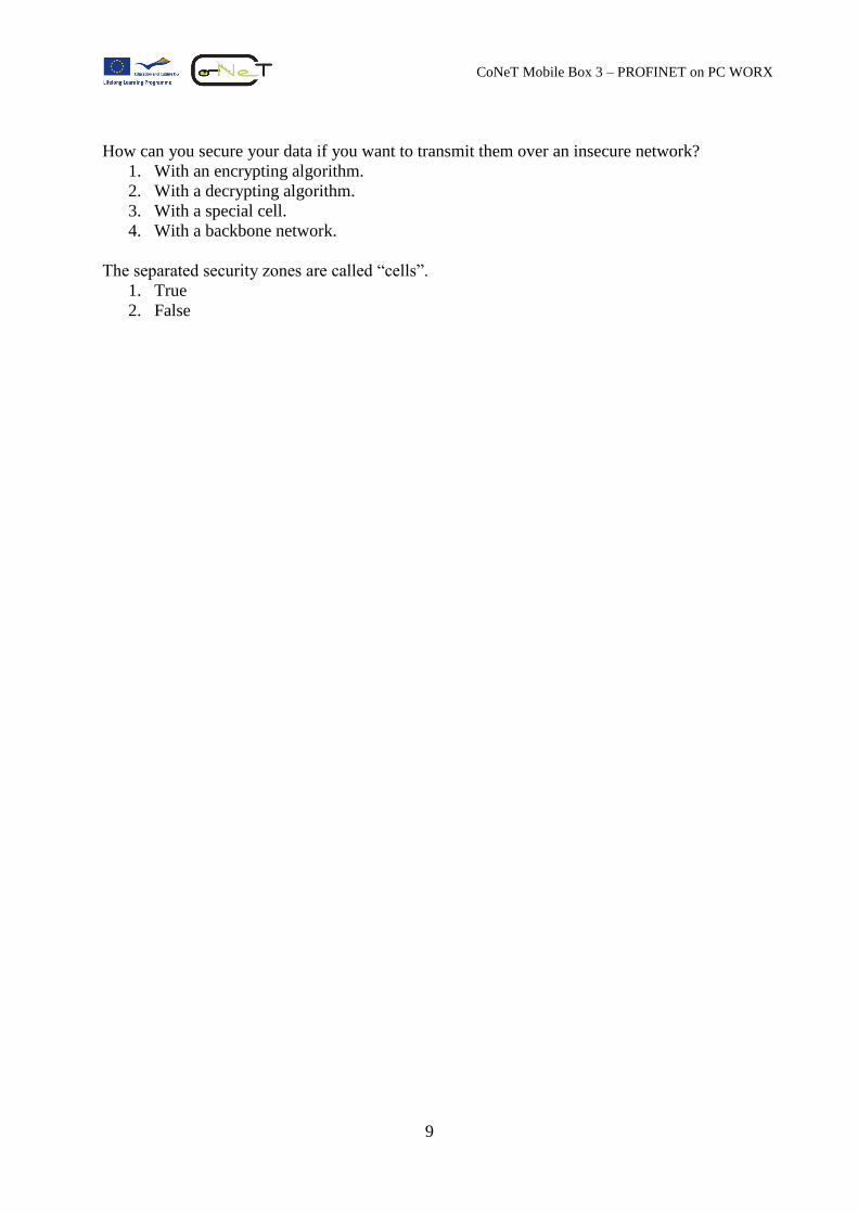
PROFINET Security Concept
The core of the PROFINET Security Concept focuses on securing networks in the separated
security zones, the so-called cells (Fig. 5). Different cells may be interconnected by a
8
CoNeT Mobile Box 3 – PROFINET on PC WORX
backbone network. Each cell can be connected to the backbone through an entry point and is
protected by using special security network components, such as switches or other security
devices. These components check the data being transmitted for their authorization and
integrity. If you want to access the secure automation devices, you can use special security
client software.
Fig. 5 PROFINET security
concept
The data traffic between secure cells or between client software and the cell can also be
encrypted using conventional encrypting algorithms. This secured connection can protect the
data from being manipulated or spied on. This is necessary, especially if you want to access
your secure automation devices over an insecure network, such as Internet.
Questions
What kind of network does PROFINET use?
1. Industrial fieldbus communication
2. Industrial Ethernet
3. Industrial Internet
4. Asynchronous Transfer Mode (ATM)
What kinds of PROFINET are there?
1. TCP and IP
2. UDP and XML
3. TCP, UDP and IP
4. IO and CBA
If you want to use a drive application, what kind of PROFINET protocol has to be
implemented?
1. NRT, because I want to access process automation.
2. RT, because I want to receive optimized data exchange transfer rate.
3. IRT, because I want to receive an immediate response.
4. TCP/IP, because it is the connection-oriented protocol.
9
CoNeT Mobile Box 3 – PROFINET on PC WORX
How can you secure your data if you want to transmit them over an insecure network?
1. With an encrypting algorithm.
2. With a decrypting algorithm.
3. With a special cell.
4. With a backbone network.
The separated security zones are called “cells”.
1. True
2. False
10
CoNeT Mobile Box 3 – PROFINET on PC WORX
PROFINET vs. PROFIBUS
For those who are already familiar with PROFIBUS, you can see PROFINET as a further
development of the PROFIBUS DP. However, in comparison to PROFIBUS, PROFINET has
many more advantages (Table 1). In this chapter, we examine some of the advantages of
PROFINET. At the end you will be able to judge whether you should use PROFINET or not.
Advantages of PROFINET
The PROFINET offers several advantages from different points of view. As a user, you can
have more flexibility, e.g., controlling your automation devices. As a PROFIBUS device
manufacturer, you still can manufacture the good old PROFIBUS field devices while plan-
ning for PROFINET devices production. So, let's take a look at the following list.
High-speed operation: The real time communication channel provides high-speed
process data exchange by bypassing the time required to process the TCP/IP stack. The
time-critical process data can then be exchanged by using RT or IRT protocols. Time-
critical alarm signals or time-uncritical diagnostic data can be set up by one installation on
one medium.
Simple network structure: The construction of Ethernet standard is very simple and easy
to implement. Furthermore, this standard is widely used in the office sector. Therefore, it
is possible to ensure compatible connections to administration departments and offices.
Cost-effective technology: If we compare the set up cost and performance of Ethernet
with other network systems, such as ATM (Asynchronous Transfer Mode) or Frame Re-
lay, you will see that Ethernet is much more cost-effective than the others. Moreover,
Ethernet will give each user the same speed regardless of where the application is actually
hosted.
One line data transfer: Using Ethernet means that you can use just one cable to transmit
all kinds of data. This, of course, results in a reduction of cable costs. By using switches,
you can then access your desired devices.
IT Software: For accessing process data or diagnostic purposes, you can use the conven-
tional software of the IT world, such as web browsers like Internet Explorer, Firefox, Op-
era, etc., or office applications, like Microsoft Office.
Simple extensible network: In PROFINET IO for example, you can add new field
devices by using the device library which allows easy extensibility. This kind of approach
lets you extend your network however you wish.
Individual settings: The field devices can be set individually, e.g., you can set up
different field devices with different cycle times on the same network. This lets you have
cyclic data at different times depending on your needs.
Seamless integration with fieldbus systems: For those who already have a fieldbus sys-
tem, e.g., PROFIBUS, DeviceNet, INTERBUS, etc., installed in their factory, PROFINET
offers the so-called proxy which has been designed to connect PROFINET and PROFI-
BUS. In this way the investment made in already installed fieldbuses is protected.
11
CoNeT Mobile Box 3 – PROFINET on PC WORX
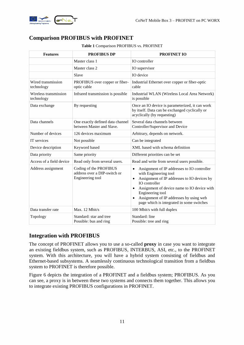
Comparison PROFIBUS with PROFINET
Table 1 Comparison PROFIBUS vs. PROFINET
Features PROFIBUS DP PROFINET IO
Master class 1 IO controller
Master class 2 IO supervisor
Slave IO device
Wired transmission
technology
PROFIBUS over copper or fiber-
optic cable
Industrial Ethernet over copper or fiber-optic
cable
Wireless transmission
technology
Infrared transmission is possible
Industrial WLAN (Wireless Local Area Network)
is possible
Data exchange
By requesting
Once an IO device is parameterized, it can work
by itself. Data can be exchanged cyclically or
acyclically (by requesting)
Data channels One exactly defined data channel
between Master and Slave.
Several data channels between
Controller/Supervisor and Device
Number of devices 126 devices maximum Arbitrary, depends on network.
IT services Not possible Can be integrated
Device description Keyword based XML based with schema definition
Data priority Same priority Different priorities can be set
Access of a field device Read only from several users. Read and write from several users possible.
Address assignment Coding of the PROFIBUS
address over a DIP-switch or
Engineering tool
Assignment of IP addresses to IO controller
with Engineering tool
Assignment of IP addresses to IO devices by
IO controller
Assignment of device name to IO device with
Engineering tool
Assignment of IP addresses by using web
page which is integrated in some switches
Data transfer rate Max. 12 Mbit/s 100 Mbit/s with full duplex
Topology Standard: star and tree
Possible: bus and ring
Standard: line
Possible: tree and ring
Integration with PROFIBUS
The concept of PROFINET allows you to use a so-called proxy in case you want to integrate
an existing fieldbus system, such as PROFIBUS, INTERBUS, ASI, etc., to the PROFINET
system. With this architecture, you will have a hybrid system consisting of fieldbus and
Ethernet-based subsystems. A seamlessly continuous technological transition from a fieldbus
system to PROFINET is therefore possible.
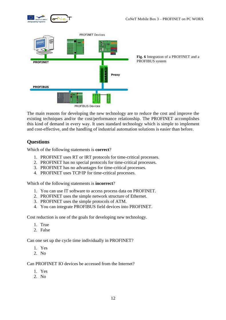
Figure 6 depicts the integration of a PROFINET and a fieldbus system; PROFIBUS. As you
can see, a proxy is in between these two systems and connects them together. This allows you
to integrate existing PROFIBUS configurations in PROFINET.
12
CoNeT Mobile Box 3 – PROFINET on PC WORX
Fig. 6 Integration of a PROFINET and a
PROFIBUS system
The main reasons for developing the new technology are to reduce the cost and improve the
existing techniques and/or the cost/performance relationship. The PROFINET accomplishes
this kind of demand in every way. It uses standard technology which is simple to implement
and cost-effective, and the handling of industrial automation solutions is easier than before.
Questions
Which of the following statements is correct?
1. PROFINET uses RT or IRT protocols for time-critical processes.
2. PROFINET has no special protocols for time-critical processes.
3. PROFINET has no advantages for time-critical processes.
4. PROFINET uses TCP/IP for time-critical processes.
Which of the following statements is incorrect?
1. You can use IT software to access process data on PROFINET.
2. PROFINET uses the simple network structure of Ethernet.
3. PROFINET uses the simple protocols of ATM.
4. You can integrate PROFIBUS field devices into PROFINET.
Cost reduction is one of the goals for developing new technology.
1. True
2. False
Can one set up the cycle time individually in PROFINET?
1. Yes
2. No
Can PROFINET IO devices be accessed from the Internet?
1. Yes
2. No
13
CoNeT Mobile Box 3 – PROFINET on PC WORX
ISO/OSI Reference Model
The ISO/OSI reference model is denoted as a layer model which one can refer to as a refer-
ence for data communication. These two acronyms stand for International Standardization
Organization and Open System Interconnection. According to the ISO/OSI reference model,
also called layer model, you can divide the communication operation into seven layers.
Every layer has a specified assignment, which can be passed to the layer above or below, ac-
cording to the task, as a service. Communication between two layers can be made by using
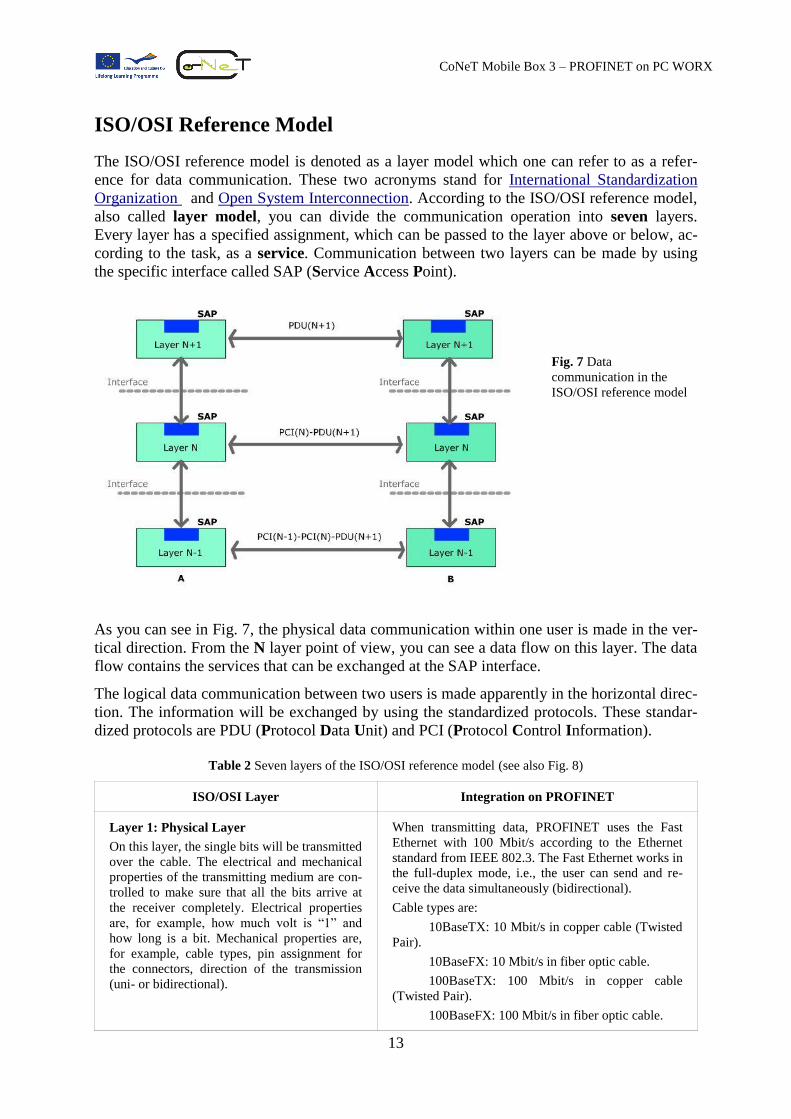
the specific interface called SAP (Service Access Point).
Fig. 7 Data
communication in the
ISO/OSI reference model
As you can see in Fig. 7, the physical data communication within one user is made in the ver-
tical direction. From the N layer point of view, you can see a data flow on this layer. The data
flow contains the services that can be exchanged at the SAP interface.
The logical data communication between two users is made apparently in the horizontal direc-
tion. The information will be exchanged by using the standardized protocols. These standar-
dized protocols are PDU (Protocol Data Unit) and PCI (Protocol Control Information).
Table 2 Seven layers of the ISO/OSI reference model (see also Fig. 8)
ISO/OSI Layer Integration on PROFINET
Layer 1: Physical Layer
On this layer, the single bits will be transmitted
over the cable. The electrical and mechanical
properties of the transmitting medium are con-
trolled to make sure that all the bits arrive at
the receiver completely. Electrical properties
are, for example, how much volt is “1” and
how long is a bit. Mechanical properties are,
for example, cable types, pin assignment for
the connectors, direction of the transmission
(uni- or bidirectional).
When transmitting data, PROFINET uses the Fast
Ethernet with 100 Mbit/s according to the Ethernet
standard from IEEE 802.3. The Fast Ethernet works in
the full-duplex mode, i.e., the user can send and re-
ceive the data simultaneously (bidirectional).
Cable types are:
10BaseTX: 10 Mbit/s in copper cable (Twisted
Pair).
10BaseFX: 10 Mbit/s in fiber optic cable.
100BaseTX: 100 Mbit/s in copper cable
(Twisted Pair).
100BaseFX: 100 Mbit/s in fiber optic cable.
14
CoNeT Mobile Box 3 – PROFINET on PC WORX
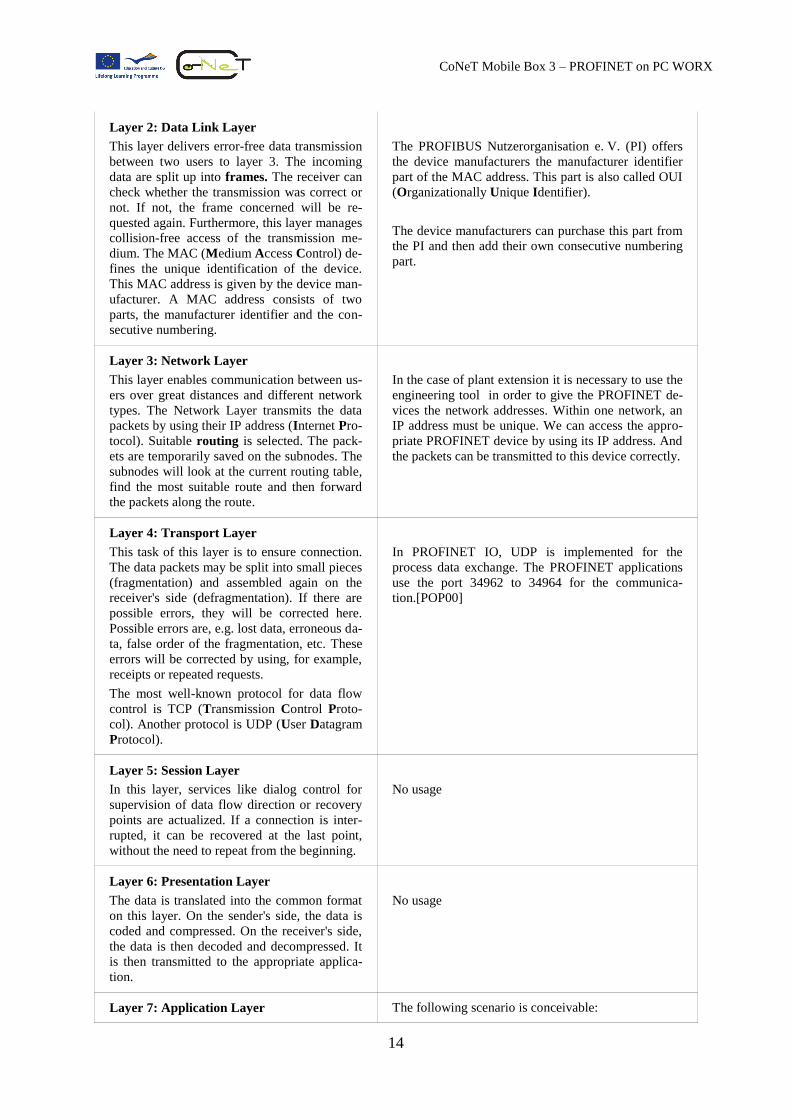
Layer 2: Data Link Layer
This layer delivers error-free data transmission
between two users to layer 3. The incoming
data are split up into frames. The receiver can
check whether the transmission was correct or
not. If not, the frame concerned will be re-
quested again. Furthermore, this layer manages
collision-free access of the transmission me-
dium. The MAC (Medium Access Control) de-
fines the unique identification of the device.
This MAC address is given by the device man-
ufacturer. A MAC address consists of two
parts, the manufacturer identifier and the con-
secutive numbering.
The PROFIBUS Nutzerorganisation e. V. (PI) offers
the device manufacturers the manufacturer identifier
part of the MAC address. This part is also called OUI
(Organizationally Unique Identifier).
The device manufacturers can purchase this part from
the PI and then add their own consecutive numbering
part.
Layer 3: Network Layer
This layer enables communication between us-
ers over great distances and different network
types. The Network Layer transmits the data
packets by using their IP address (Internet Pro-
tocol). Suitable routing is selected. The pack-
ets are temporarily saved on the subnodes. The
subnodes will look at the current routing table,
find the most suitable route and then forward
the packets along the route.
In the case of plant extension it is necessary to use the
engineering tool in order to give the PROFINET de-
vices the network addresses. Within one network, an
IP address must be unique. We can access the appro-
priate PROFINET device by using its IP address. And
the packets can be transmitted to this device correctly.
Layer 4: Transport Layer
This task of this layer is to ensure connection.
The data packets may be split into small pieces
(fragmentation) and assembled again on the
receiver's side (defragmentation). If there are
possible errors, they will be corrected here.
Possible errors are, e.g. lost data, erroneous da-
ta, false order of the fragmentation, etc. These
errors will be corrected by using, for example,
receipts or repeated requests.
The most well-known protocol for data flow
control is TCP (Transmission Control Proto-
col). Another protocol is UDP (User Datagram
Protocol).
In PROFINET IO, UDP is implemented for the
process data exchange. The PROFINET applications
use the port 34962 to 34964 for the communica-
tion.[POP00]
Layer 5: Session Layer
In this layer, services like dialog control for
supervision of data flow direction or recovery
points are actualized. If a connection is inter-
rupted, it can be recovered at the last point,
without the need to repeat from the beginning.
No usage
Layer 6: Presentation Layer
The data is translated into the common format
on this layer. On the sender's side, the data is
coded and compressed. On the receiver's side,
the data is then decoded and decompressed. It
is then transmitted to the appropriate applica-
tion.
No usage
Layer 7: Application Layer The following scenario is conceivable:
15
CoNeT Mobile Box 3 – PROFINET on PC WORX
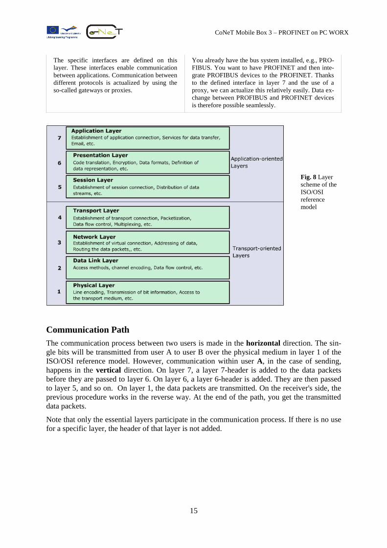
The specific interfaces are defined on this
layer. These interfaces enable communication
between applications. Communication between
different protocols is actualized by using the
so-called gateways or proxies.
You already have the bus system installed, e.g., PRO-
FIBUS. You want to have PROFINET and then inte-
grate PROFIBUS devices to the PROFINET. Thanks
to the defined interface in layer 7 and the use of a
proxy, we can actualize this relatively easily. Data ex-
change between PROFIBUS and PROFINET devices
is therefore possible seamlessly.
Fig. 8 Layer
scheme of the
ISO/OSI
reference
model
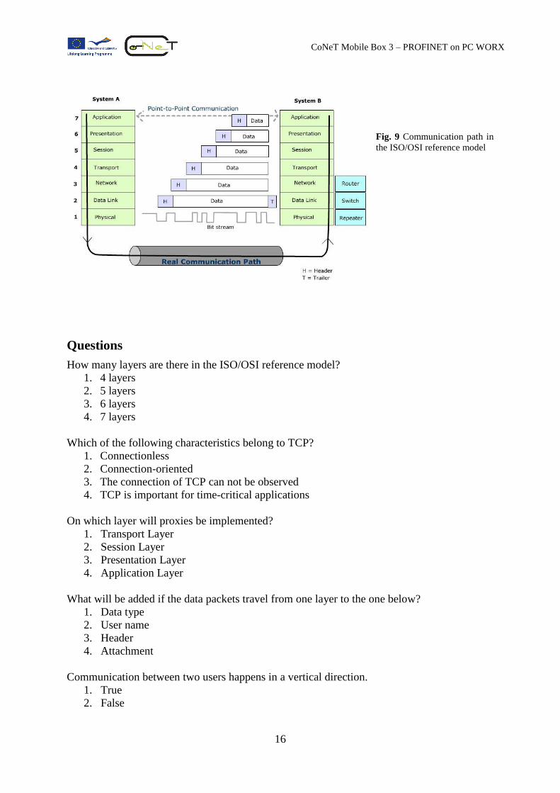
Communication Path
The communication process between two users is made in the horizontal direction. The sin-
gle bits will be transmitted from user A to user B over the physical medium in layer 1 of the
ISO/OSI reference model. However, communication within user A, in the case of sending,
happens in the vertical direction. On layer 7, a layer 7-header is added to the data packets
before they are passed to layer 6. On layer 6, a layer 6-header is added. They are then passed
to layer 5, and so on. On layer 1, the data packets are transmitted. On the receiver's side, the
previous procedure works in the reverse way. At the end of the path, you get the transmitted
data packets.
Note that only the essential layers participate in the communication process. If there is no use
for a specific layer, the header of that layer is not added.
16
CoNeT Mobile Box 3 – PROFINET on PC WORX
Fig. 9 Communication path in
the ISO/OSI reference model
Questions
How many layers are there in the ISO/OSI reference model?
1. 4 layers
2. 5 layers
3. 6 layers
4. 7 layers
Which of the following characteristics belong to TCP?
1. Connectionless
2. Connection-oriented
3. The connection of TCP can not be observed
4. TCP is important for time-critical applications
On which layer will proxies be implemented?
1. Transport Layer
2. Session Layer
3. Presentation Layer
4. Application Layer
What will be added if the data packets travel from one layer to the one below?
1. Data type
2. User name
3. Header
4. Attachment
Communication between two users happens in a vertical direction.
1. True
2. False
17
CoNeT Mobile Box 3 – PROFINET on PC WORX
Ethernet Basics
Short History
Ethernet is a kind of computer network that is part of the most commonly installed local net-
works in the world. The most well known examples are LAN (Local Area Network) and
WLAN (Wireless Local Area Network).
The history of the Ethernet began at the beginning
of the seventies. The US Company XEROX intro-
duced the innovative concept of the Ethernet. With
Ethernet, computers can communicate among
themselves without prior knowledge of one anoth-
er.
On February 1980, the working group 802 of the
American IEEE (Institute of Electrical and Elec-
tronics Engineers) officially defined the first stan-
dard for LAN communication. The transmission rate was set at 10 Mbps (Megabits per
second). At the time of writing (January 2011) and thanks to the further development of
transmission techniques, the standard transmission rate of the Ethernet is now 100 Mbps.
This kind of transmission rate is also called Fast Ethernet. In the near future, we can expect a
transmission rate of 1 Gbps (Gigabits per second) to become the new standard. This transmis-
sion rate is also called Gigabit Ethernet.
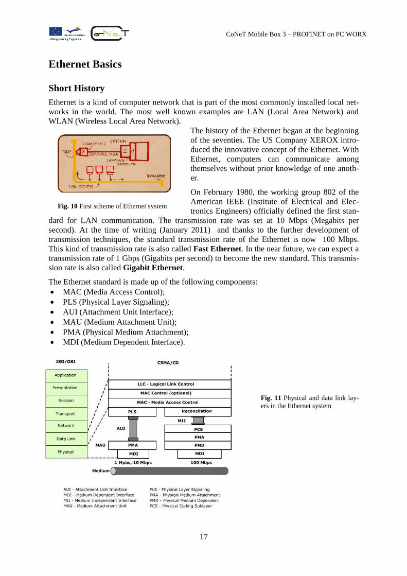
The Ethernet standard is made up of the following components:
MAC (Media Access Control);
PLS (Physical Layer Signaling);
AUI (Attachment Unit Interface);
MAU (Medium Attachment Unit);
PMA (Physical Medium Attachment);
MDI (Medium Dependent Interface).
Fig. 11 Physical and data link lay-
ers in the Ethernet system
Fig. 10 First scheme of Ethernet system
18
CoNeT Mobile Box 3 – PROFINET on PC WORX
Access Method
Ethernet uses the CSMA/CD network access method to control access to the network. The
devices attached to the network cable listen to the transmission medium and begin to transmit
data as soon as the medium is available. If the medium is in use, the devices wait before
transmitting. There is no central station monitoring or controlling access to the network.
CS (Carrier Sense): The devices check whether the medium is available.
MA (Multiple Access): MA indicates that many devices can connect to or share the same
network. If the medium is available, each device can begin to transmit data.
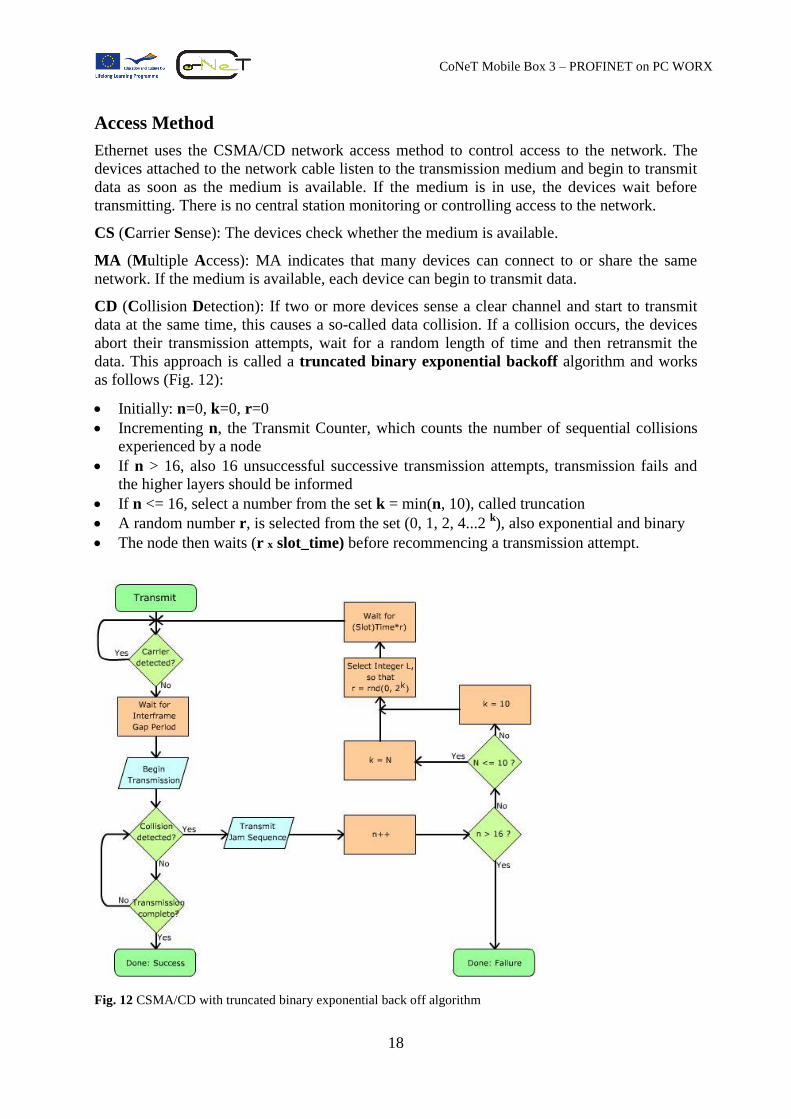
CD (Collision Detection): If two or more devices sense a clear channel and start to transmit
data at the same time, this causes a so-called data collision. If a collision occurs, the devices
abort their transmission attempts, wait for a random length of time and then retransmit the
data. This approach is called a truncated binary exponential backoff algorithm and works
as follows (Fig. 12):
Initially: n=0, k=0, r=0
Incrementing n, the Transmit Counter, which counts the number of sequential collisions
experienced by a node
If n > 16, also 16 unsuccessful successive transmission attempts, transmission fails and
the higher layers should be informed
If n <= 16, select a number from the set k = min(n, 10), called truncation
A random number r, is selected from the set (0, 1, 2, 4...2 k), also exponential and binary
The node then waits (r x slot_time) before recommencing a transmission attempt.
Fig. 12 CSMA/CD with truncated binary exponential back off algorithm
19
CoNeT Mobile Box 3 – PROFINET on PC WORX
Standard Ethernet Frames
What are frames?
We define “frames” as the format of data packets which are transmitted from A to B on the
wire or wirelessly. A frame usually begins with a so-called preamble, which would show on
the actual physical hardware as start bits. At the end of a frame, there is a so-called Frame
Check Sequence (FCS). FCS is required by all physical hardware for data integrity checking
purpose.
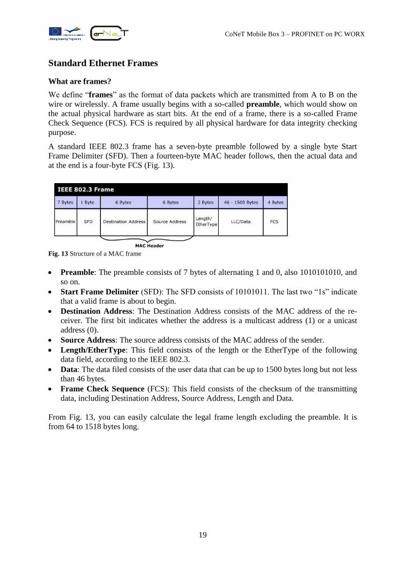
A standard IEEE 802.3 frame has a seven-byte preamble followed by a single byte Start
Frame Delimiter (SFD). Then a fourteen-byte MAC header follows, then the actual data and
at the end is a four-byte FCS (Fig. 13).
Fig. 13 Structure of a MAC frame
Preamble: The preamble consists of 7 bytes of alternating 1 and 0, also 1010101010, and
so on.
Start Frame Delimiter (SFD): The SFD consists of 10101011. The last two “1s” indicate
that a valid frame is about to begin.
Destination Address: The Destination Address consists of the MAC address of the re-
ceiver. The first bit indicates whether the address is a multicast address (1) or a unicast
address (0).
Source Address: The source address consists of the MAC address of the sender.
Length/EtherType: This field consists of the length or the EtherType of the following
data field, according to the IEEE 802.3.
Data: The data filed consists of the user data that can be up to 1500 bytes long but not less
than 46 bytes.
Frame Check Sequence (FCS): This field consists of the checksum of the transmitting
data, including Destination Address, Source Address, Length and Data.
From Fig. 13, you can easily calculate the legal frame length excluding the preamble. It is
from 64 to 1518 bytes long.
20
CoNeT Mobile Box 3 – PROFINET on PC WORX
MAC Address
If you want to send a letter to a specified person, you have to know his/her address in order
that he/she receives your letter. In the Ethernet world, too, each active Ethernet component
must have a unique address in order to be identified.
The MAC (Media Access Control) address is the hardware address of the devices that partici-
pate in the network. There are many names for MAC addresses, such as Ethernet address,
physical address, station address or adapter card address. The MAC address is assigned by the
device manufacturer and is 6 bytes long.
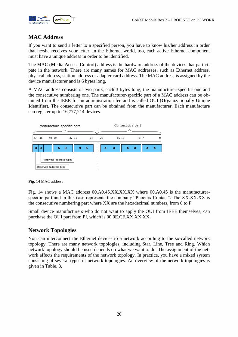
A MAC address consists of two parts, each 3 bytes long, the manufacturer-specific one and
the consecutive numbering one. The manufacturer-specific part of a MAC address can be ob-
tained from the IEEE for an administration fee and is called OUI (Organizationally Unique
Identifier). The consecutive part can be obtained from the manufacturer. Each manufacture
can register up to 16,777,214 devices.
Fig. 14 MAC address
Fig. 14 shows a MAC address 00.A0.45.XX.XX.XX where 00.A0.45 is the manufacturer-
specific part and in this case represents the company “Phoenix Contact”. The XX.XX.XX is
the consecutive numbering part where XX are the hexadecimal numbers, from 0 to F.
Small device manufacturers who do not want to apply the OUI from IEEE themselves, can
purchase the OUI part from PI, which is 00.0E.CF.XX.XX.XX.
Network Topologies
You can interconnect the Ethernet devices to a network according to the so-called network
topology. There are many network topologies, including Star, Line, Tree and Ring. Which
network topology should be used depends on what we want to do. The assignment of the net-
work affects the requirements of the network topology. In practice, you have a mixed system
consisting of several types of network topologies. An overview of the network topologies is
given in Table. 3.
21
CoNeT Mobile Box 3 – PROFINET on PC WORX
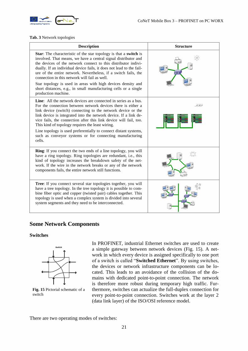
Tab. 3 Network topologies
Description Structure
Star: The characteristic of the star topology is that a switch is
involved. That means, we have a central signal distributor and
the devices of the network connect to this distributor indivi-
dually. If an individual device fails, it does not lead to the fail-
ure of the entire network. Nevertheless, if a switch fails, the
connection in this network will fail as well.
Star topology is used in areas with high devices density and
short distances, e.g., in small manufacturing cells or a single
production machine.
Line: All the network devices are connected in series as a bus.
For the connection between network devices there is either a
link device (switch) connecting to the network device or the
link device is integrated into the network device. If a link de-
vice fails, the connection after this link device will fail, too.
This kind of topology requires the least wiring.
Line topology is used preferentially to connect distant systems,
such as conveyor systems or for connecting manufacturing
cells.
Ring: If you connect the two ends of a line topology, you will
have a ring topology. Ring topologies are redundant, i.e., this
kind of topology increases the breakdown safety of the net-
work. If the wire in the network breaks or any of the network
components fails, the entire network still functions.
Tree: If you connect several star topologies together, you will
have a tree topology. In the tree topology it is possible to com-
bine fiber optic and copper (twisted pair) cables together. This
topology is used when a complex system is divided into several
system segments and they need to be interconnected.
Some Network Components
Switches
In PROFINET, industrial Ethernet switches are used to create
a simple gateway between network devices (Fig. 15). A net-
work in which every device is assigned specifically to one port
of a switch is called “Switched Ethernet”. By using switches,
the devices or network infrastructure components can be lo-
cated. This leads to an avoidance of the collision of the do-
mains with dedicated point-to-point connection. The network
is therefore more robust during temporary high traffic. Fur-
thermore, switches can actualize the full-duplex connection for
every point-to-point connection. Switches work at the layer 2
(data link layer) of the ISO/OSI reference model.
There are two operating modes of switches:
Fig. 15 Pictorial schematic of a
switch
22
CoNeT Mobile Box 3 – PROFINET on PC WORX
Cut-Through Switches: A cut-through switch or “on the fly” switch forwards a data
packet immediately after receiving the 6 bytes long destination address. This way, the de-
lay time between sender and receiver is reduced and the data packets will not be buffered
completely. The delay time of a current cut-through switch is between 5 to 60 microse-
conds.
Store-and-Forward Switches: A store-and-forward switch examines every data packet.
The data packets will be buffered briefly, checked for correctness or validity, and then ei-
ther rejected or forwarded. This way causes an increase in the delay time for forwarding
data packets. On the other hand, no faulty data packets will be transmitted. The delay time
of a data packet depends on its frame length. A short frame length has a delay time be-
tween 8-100 microseconds, and a long one has delay time up to 1.5 milliseconds.
Furthermore, switches can have the following properties:
Blocking or Wire speed (non-blocking): If a switch can serve all services at the same
time, then it is non-blocking. However, if it only has restricted capacity, then it is a block-
ing switch.
Managed or Unmanaged: If a switch just uses the address table for transmitting the
data packets, it is called “unmanaged”. However, if we can insert some additional criteria
for the data transmission, such as, the priority of the packet, the priority of the single IP
address, etc., it is called “managed”. Please note that the connection between networks
with different transferring rates can only be done with store-and-forward switches.
In PROFINET, a switch should forward a data packet in less than 10 microseconds after re-
ceiving it and support at least 4 priority classes. Since switches are active network compo-
nents, and they will lead to the failure of the entire network if they fail, the Rapid Spanning
Tree Protocol (RSTP) is used to detect this. The idea behind this protocol is that when the
topology changes are indicated, the network structure will not be deleted immediately. The
alternative routes will be calculated and a new tree will be created. This method can reduce
the network downtime from 30 seconds to less than one second.
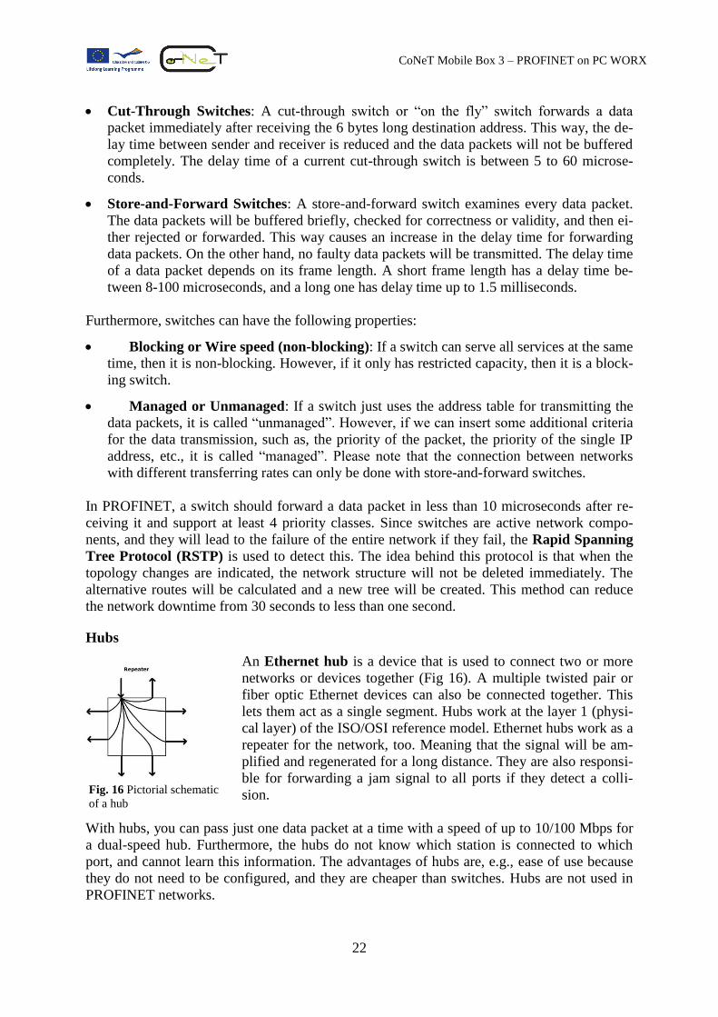
Hubs
An Ethernet hub is a device that is used to connect two or more
networks or devices together (Fig 16). A multiple twisted pair or
fiber optic Ethernet devices can also be connected together. This
lets them act as a single segment. Hubs work at the layer 1 (physi-
cal layer) of the ISO/OSI reference model. Ethernet hubs work as a
repeater for the network, too. Meaning that the signal will be am-
plified and regenerated for a long distance. They are also responsi-
ble for forwarding a jam signal to all ports if they detect a colli-
sion.
With hubs, you can pass just one data packet at a time with a speed of up to 10/100 Mbps for
a dual-speed hub. Furthermore, the hubs do not know which station is connected to which
port, and cannot learn this information. The advantages of hubs are, e.g., ease of use because
they do not need to be configured, and they are cheaper than switches. Hubs are not used in
PROFINET networks.
Fig. 16 Pictorial schematic
of a hub
23
CoNeT Mobile Box 3 – PROFINET on PC WORX
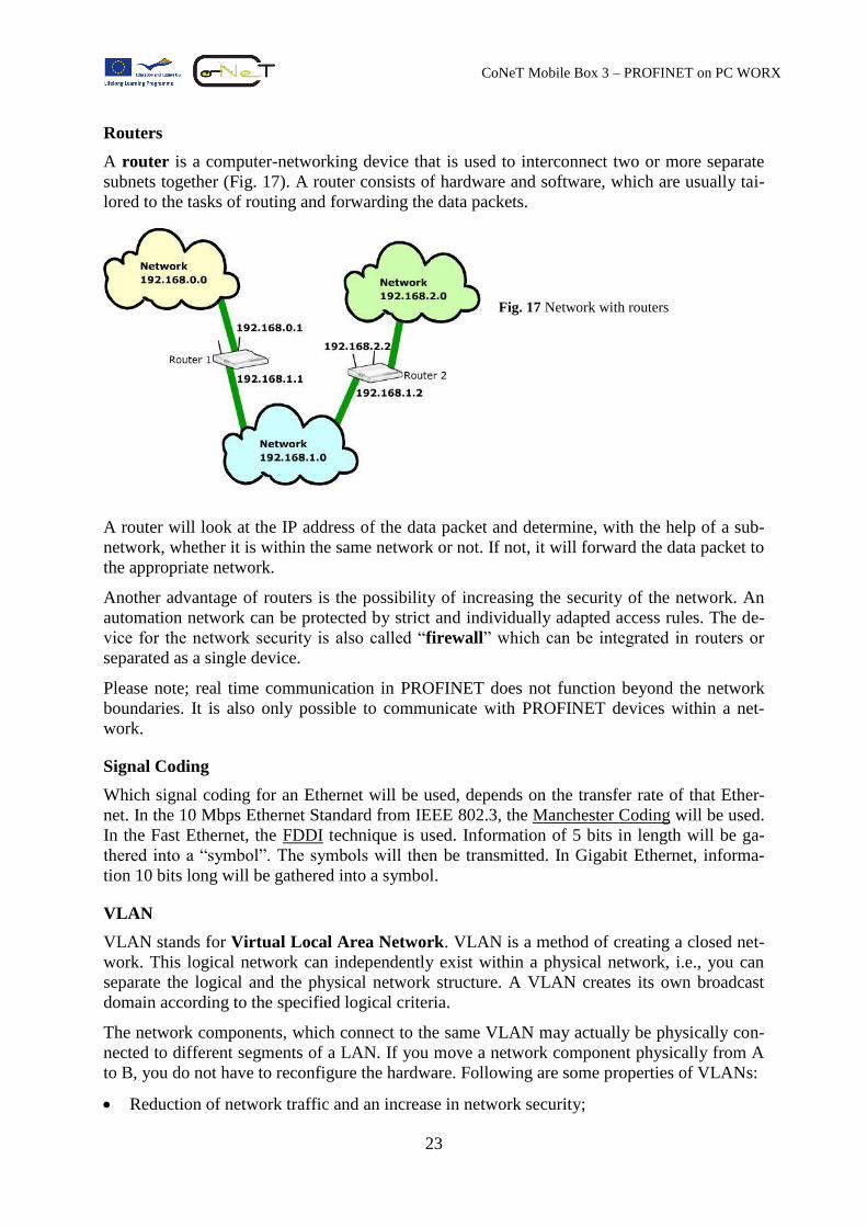
Routers
A router is a computer-networking device that is used to interconnect two or more separate
subnets together (Fig. 17). A router consists of hardware and software, which are usually tai-
lored to the tasks of routing and forwarding the data packets.
Fig. 17 Network with routers
A router will look at the IP address of the data packet and determine, with the help of a sub-
network, whether it is within the same network or not. If not, it will forward the data packet to
the appropriate network.
Another advantage of routers is the possibility of increasing the security of the network. An
automation network can be protected by strict and individually adapted access rules. The de-
vice for the network security is also called “firewall” which can be integrated in routers or
separated as a single device.
Please note; real time communication in PROFINET does not function beyond the network
boundaries. It is also only possible to communicate with PROFINET devices within a net-
work.
Signal Coding
Which signal coding for an Ethernet will be used, depends on the transfer rate of that Ether-
net. In the 10 Mbps Ethernet Standard from IEEE 802.3, the Manchester Coding will be used.
In the Fast Ethernet, the FDDI technique is used. Information of 5 bits in length will be ga-
thered into a “symbol”. The symbols will then be transmitted. In Gigabit Ethernet, informa-
tion 10 bits long will be gathered into a symbol.
VLAN
VLAN stands for Virtual Local Area Network. VLAN is a method of creating a closed net-
work. This logical network can independently exist within a physical network, i.e., you can
separate the logical and the physical network structure. A VLAN creates its own broadcast
domain according to the specified logical criteria.
The network components, which connect to the same VLAN may actually be physically con-
nected to different segments of a LAN. If you move a network component physically from A
to B, you do not have to reconfigure the hardware. Following are some properties of VLANs:
Reduction of network traffic and an increase in network security;
24
CoNeT Mobile Box 3 – PROFINET on PC WORX
Reduction of management effort for creating subnetworks;
Reduction of hardware requirement and cost;
The network components can be classified into function groups, e.g., servers, IPCs, etc.;
Physical distance does not affect the distribution of the tasks for devices;
Easy mapping of function units to the network structure.
Questions
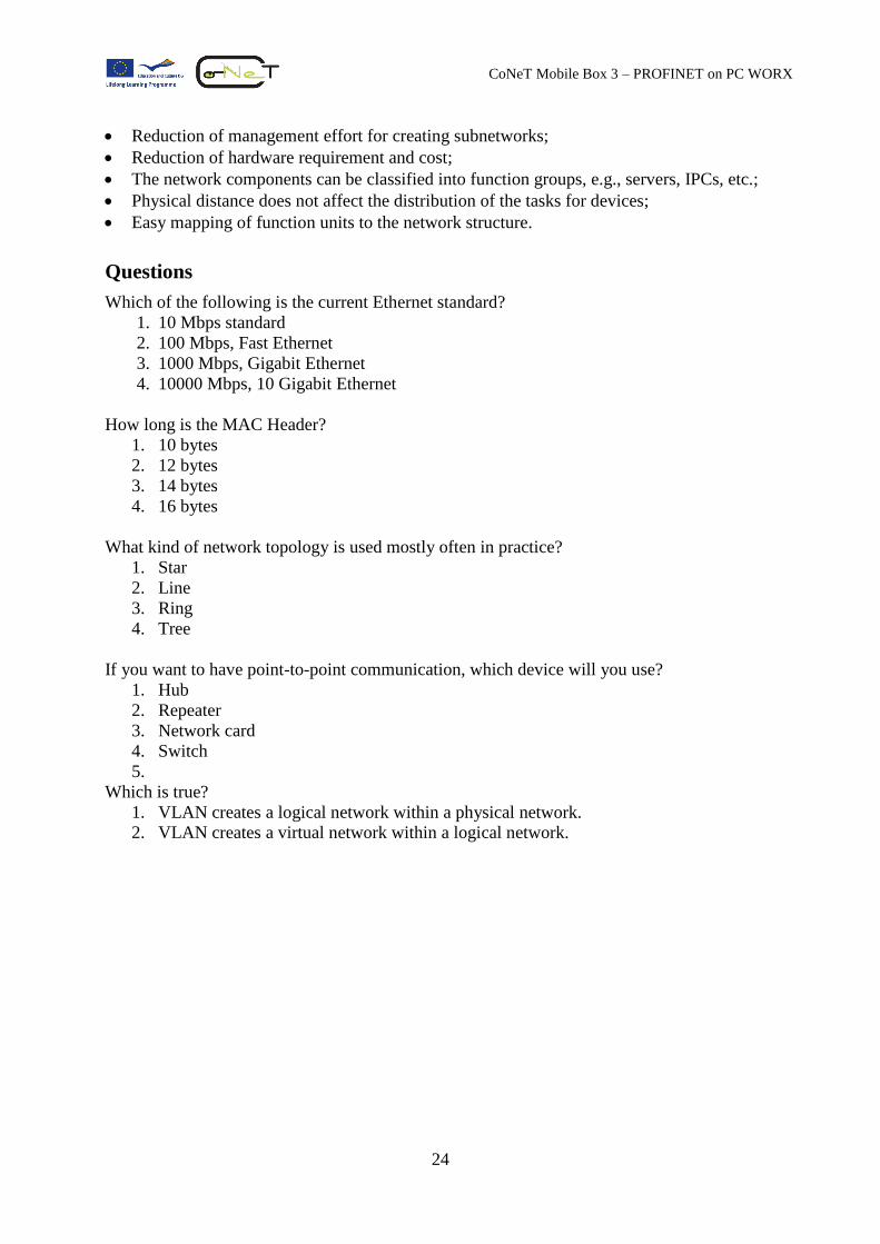
Which of the following is the current Ethernet standard?
1. 10 Mbps standard
2. 100 Mbps, Fast Ethernet
3. 1000 Mbps, Gigabit Ethernet
4. 10000 Mbps, 10 Gigabit Ethernet
How long is the MAC Header?
1. 10 bytes
2. 12 bytes
3. 14 bytes
4. 16 bytes
What kind of network topology is used mostly often in practice?
1. Star
2. Line
3. Ring
4. Tree
If you want to have point-to-point communication, which device will you use?
1. Hub
2. Repeater
3. Network card
4. Switch
5.
Which is true?
1. VLAN creates a logical network within a physical network.
2. VLAN creates a virtual network within a logical network.
25
CoNeT Mobile Box 3 – PROFINET on PC WORX
PROFINET Cabling and Cable-jack Systems
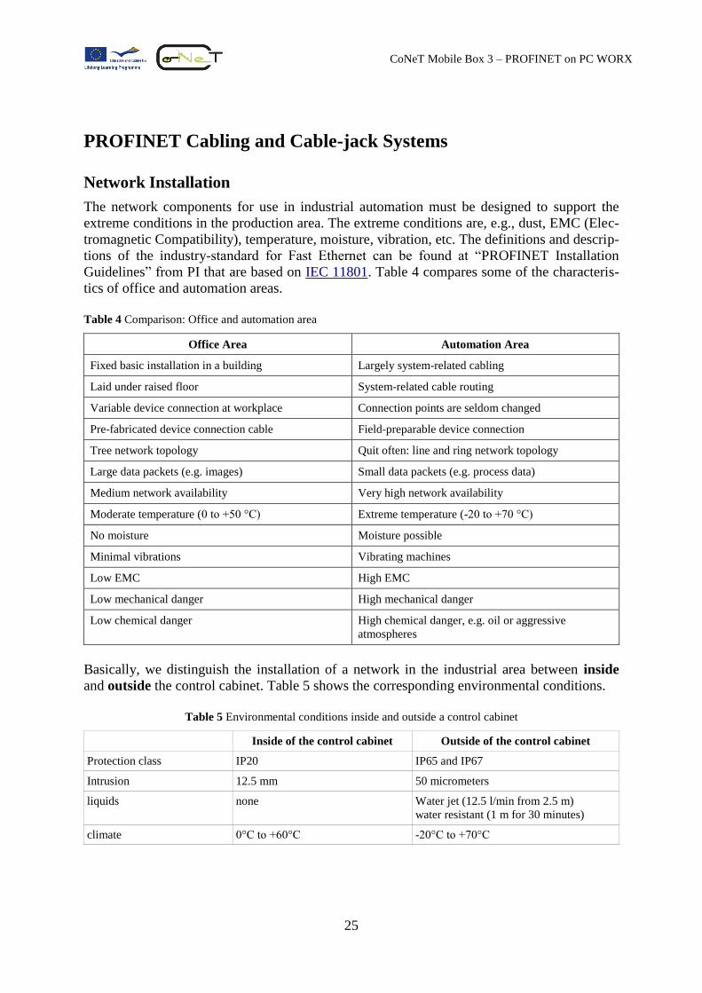
Network Installation
The network components for use in industrial automation must be designed to support the
extreme conditions in the production area. The extreme conditions are, e.g., dust, EMC (Elec-
tromagnetic Compatibility), temperature, moisture, vibration, etc. The definitions and descrip-
tions of the industry-standard for Fast Ethernet can be found at “PROFINET Installation
Guidelines” from PI that are based on IEC 11801. Table 4 compares some of the characteris-
tics of office and automation areas.
Table 4 Comparison: Office and automation area
Office Area Automation Area
Fixed basic installation in a building Largely system-related cabling
Laid under raised floor System-related cable routing
Variable device connection at workplace Connection points are seldom changed
Pre-fabricated device connection cable Field-preparable device connection
Tree network topology Quit often: line and ring network topology
Large data packets (e.g. images) Small data packets (e.g. process data)
Medium network availability Very high network availability
Moderate temperature (0 to +50 °C) Extreme temperature (-20 to +70 °C)
No moisture Moisture possible
Minimal vibrations Vibrating machines
Low EMC High EMC
Low mechanical danger High mechanical danger
Low chemical danger High chemical danger, e.g. oil or aggressive
atmospheres
Basically, we distinguish the installation of a network in the industrial area between inside
and outside the control cabinet. Table 5 shows the corresponding environmental conditions.
Table 5 Environmental conditions inside and outside a control cabinet
Inside of the control cabinet Outside of the control cabinet
Protection class IP20 IP65 and IP67
Intrusion 12.5 mm 50 micrometers
liquids none Water jet (12.5 l/min from 2.5 m)
water resistant (1 m for 30 minutes)
climate 0°C to +60°C -20°C to +70°C
26
CoNeT Mobile Box 3 – PROFINET on PC WORX
Cables
Like other network components described above, the industry-standard cables have to with-
stand extreme mechanical stress in the production area. Therefore, they have special proper-
ties that are described in the “PROFINET Installation Guide”.
Basically, you have 2 cable types, cables with copper and cables with fiber optic. Further-
more, you have a so-called hybrid cable that transmits not only process data but also the
power as well. It is also possible to transmit process data wirelessly.
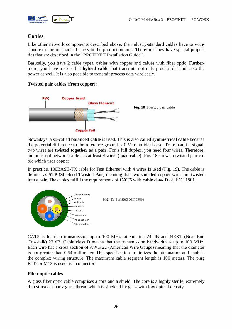
Twisted pair cables (from copper):
Fig. 18 Twisted pair cable
Nowadays, a so-called balanced cable is used. This is also called symmetrical cable because
the potential difference to the reference ground is 0 V in an ideal case. To transmit a signal,
two wires are twisted together as a pair. For a full duplex, you need four wires. Therefore,
an industrial network cable has at least 4 wires (quad cable). Fig. 18 shows a twisted pair ca-
ble which uses copper.
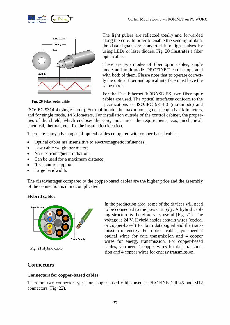
In practice, 100BASE-TX cable for Fast Ethernet with 4 wires is used (Fig. 19). The cable is
defined as STP (Shielded Twisted Pair) meaning that two shielded copper wires are twisted
into a pair. The cables fulfill the requirements of CAT5 with cable class D of IEC 11801.
Fig. 19 Twisted pair cable
CAT5 is for data transmission up to 100 MHz, attenuation 24 dB and NEXT (Near End
Crosstalk) 27 dB. Cable class D means that the transmission bandwidth is up to 100 MHz.
Each wire has a cross section of AWG 22 (American Wire Gauge) meaning that the diameter
is not greater than 0.64 millimeter. This specification minimizes the attenuation and enables
the complex wiring structure. The maximum cable segment length is 100 meters. The plug
RJ45 or M12 is used as a connector.
Fiber optic cables
A glass fiber optic cable comprises a core and a shield. The core is a highly sterile, extremely
thin silica or quartz glass thread which is shielded by glass with low optical density.
27
CoNeT Mobile Box 3 – PROFINET on PC WORX
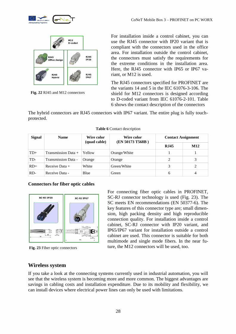
The light pulses are reflected totally and forwarded
along the core. In order to enable the sending of data,
the data signals are converted into light pulses by
using LEDs or laser diodes. Fig. 20 illustrates a fiber
optic cable.
There are two modes of fiber optic cables, single
mode and multimode. PROFINET can be operated
with both of them. Please note that to operate correct-
ly the optical fiber and optical interface must have the
same mode.
For the Fast Ethernet 100BASE-FX, two fiber optic
cables are used. The optical interfaces conform to the
specifications of ISO/IEC 9314-3 (multimode) and
ISO/IEC 9314-4 (single mode). For multimode, the maximum segment length is 2 kilometers,
and for single mode, 14 kilometers. For installation outside of the control cabinet, the proper-
ties of the shield, which encloses the core, must meet the requirements, e.g., mechanical,
chemical, thermal, etc., for the installation location.
There are many advantages of optical cables compared with copper-based cables:
Optical cables are insensitive to electromagnetic influences;
Low cable weight per meter;
No electromagnetic radiation;
Can be used for a maximum distance;
Resistant to tapping;
Large bandwidth.
The disadvantages compared to the copper-based cables are the higher price and the assembly
of the connection is more complicated.
Hybrid cables
In the production area, some of the devices will need
to be connected to the power supply. A hybrid cabl-
ing structure is therefore very useful (Fig. 21). The
voltage is 24 V. Hybrid cables contain wires (optical
or copper-based) for both data signal and the trans-
mission of energy. For optical cables, you need 2
optical wires for data transmission and 4 copper
wires for energy transmission. For copper-based
cables, you need 4 copper wires for data transmis-
sion and 4 copper wires for energy transmission.
Connectors
Connectors for copper-based cables
There are two connector types for copper-based cables used in PROFINET: RJ45 and M12
connectors (Fig. 22).
Fig. 20 Fiber optic cable
Fig. 21 Hybrid cable
28
CoNeT Mobile Box 3 – PROFINET on PC WORX
For installation inside a control cabinet, you can
use the RJ45 connector with IP20 variant that is
compliant with the connectors used in the office
area. For installation outside the control cabinet,
the connectors must satisfy the requirements for
the extreme conditions in the installation area.
Here, the RJ45 connector with IP65 or IP67 va-
riant, or M12 is used.
The RJ45 connectors specified for PROFINET are
the variants 14 and 5 in the IEC 61076-3-106. The
shield for M12 connectors is designed according
to D-coded variant from IEC 61076-2-101. Table
6 shows the contact description of the connectors
The hybrid connectors are RJ45 connectors with IP67 variant. The entire plug is fully touch-
protected.
Table 6 Contact description
Signal Name Wire color
(quad cable)
Wire color
(EN 50173 T568B )
Contact Assignment
RJ45 M12
TD+ Transmission Data + Yellow Orange/White 1 1
TD- Transmission Data - Orange Orange 2 3
RD+ Receive Data + White Green/White 3 2
RD- Receive Data - Blue Green 6 4
Connectors for fiber optic cables
For connecting fiber optic cables in PROFINET,
SC-RJ connector technology is used (Fig. 23). The
SC meets EN recommendations (EN 50377-6). The
key features of this connector type are; small dimen-
sion, high packing density and high reproducible
connection quality. For installation inside a control
cabinet, SC-RJ connector with IP20 variant, and
IP65/IP67 variant for installation outside a control
cabinet are used. This connector is suitable for both
multimode and single mode fibers. In the near fu-
ture, the M12 connectors will be used, too.
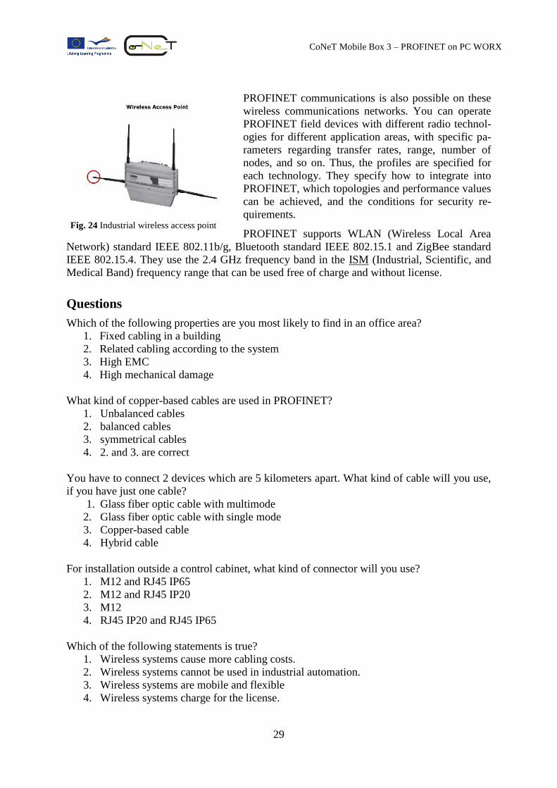
Wireless system
If you take a look at the connecting systems currently used in industrial automation, you will
see that the wireless system is becoming more and more common. The biggest advantages are
savings in cabling costs and installation expenditure. Due to its mobility and flexibility, we
can install devices where electrical power lines can only be used with limitations.
Fig. 22 RJ45 and M12 connectors
Fig. 23 Fiber optic connectors
29
CoNeT Mobile Box 3 – PROFINET on PC WORX
PROFINET communications is also possible on these
wireless communications networks. You can operate
PROFINET field devices with different radio technol-
ogies for different application areas, with specific pa-
rameters regarding transfer rates, range, number of
nodes, and so on. Thus, the profiles are specified for
each technology. They specify how to integrate into
PROFINET, which topologies and performance values
can be achieved, and the conditions for security re-
quirements.
PROFINET supports WLAN (Wireless Local Area
Network) standard IEEE 802.11b/g, Bluetooth standard IEEE 802.15.1 and ZigBee standard
IEEE 802.15.4. They use the 2.4 GHz frequency band in the ISM (Industrial, Scientific, and
Medical Band) frequency range that can be used free of charge and without license.
Questions
Which of the following properties are you most likely to find in an office area?
1. Fixed cabling in a building
2. Related cabling according to the system
3. High EMC
4. High mechanical damage
What kind of copper-based cables are used in PROFINET?
1. Unbalanced cables
2. balanced cables
3. symmetrical cables
4. 2. and 3. are correct
You have to connect 2 devices which are 5 kilometers apart. What kind of cable will you use,
if you have just one cable?
1. Glass fiber optic cable with multimode
2. Glass fiber optic cable with single mode
3. Copper-based cable
4. Hybrid cable
For installation outside a control cabinet, what kind of connector will you use?
1. M12 and RJ45 IP65
2. M12 and RJ45 IP20
3. M12
4. RJ45 IP20 and RJ45 IP65
Which of the following statements is true?
1. Wireless systems cause more cabling costs.
2. Wireless systems cannot be used in industrial automation.
3. Wireless systems are mobile and flexible
4. Wireless systems charge for the license.
Fig. 24 Industrial wireless access point
30
CoNeT Mobile Box 3 – PROFINET on PC WORX
Internet Protocol Family
When you want to communicate with people you all have to use the same language. Likewise,
in the information technology (IT) world, where protocols are used as a common language
that IT devices use to communicate with each other. There are many protocols used in IT.
Some are vendor-independent, but some are proprietary. Let’s take a look at some of the re-
quired protocols in industrial automation using Ethernet.
Internet Protocol (IP)
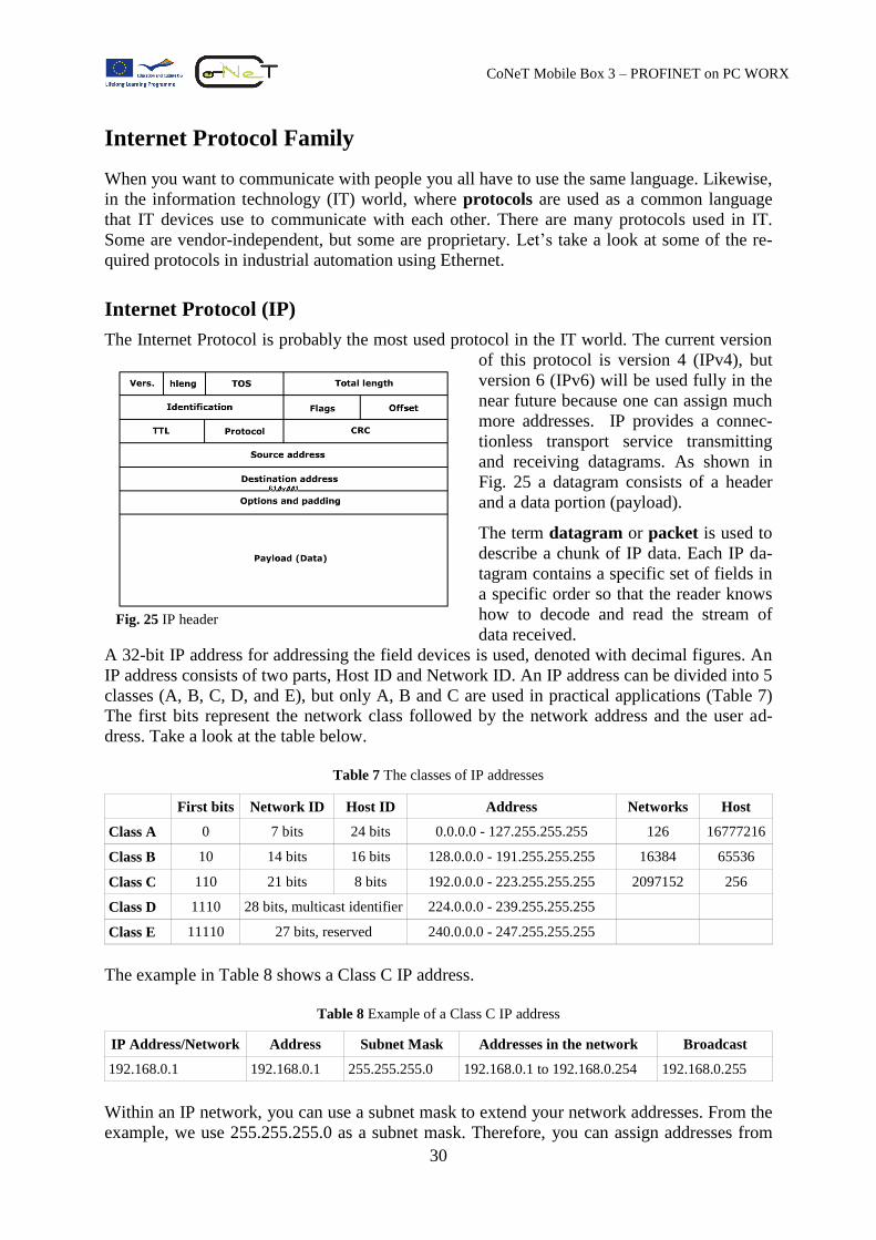
The Internet Protocol is probably the most used protocol in the IT world. The current version
of this protocol is version 4 (IPv4), but
version 6 (IPv6) will be used fully in the
near future because one can assign much
more addresses. IP provides a connec-
tionless transport service transmitting
and receiving datagrams. As shown in
Fig. 25 a datagram consists of a header
and a data portion (payload).
The term datagram or packet is used to
describe a chunk of IP data. Each IP da-
tagram contains a specific set of fields in
a specific order so that the reader knows
how to decode and read the stream of
data received.
A 32-bit IP address for addressing the field devices is used, denoted with decimal figures. An
IP address consists of two parts, Host ID and Network ID. An IP address can be divided into 5
classes (A, B, C, D, and E), but only A, B and C are used in practical applications (Table 7)
The first bits represent the network class followed by the network address and the user ad-
dress. Take a look at the table below.
Table 7 The classes of IP addresses
First bits Network ID Host ID Address Networks Host
Class A 0 7 bits 24 bits 0.0.0.0 - 127.255.255.255 126 16777216
Class B 10 14 bits 16 bits 128.0.0.0 - 191.255.255.255 16384 65536
Class C 110 21 bits 8 bits 192.0.0.0 - 223.255.255.255 2097152 256
Class D 1110 28 bits, multicast identifier 224.0.0.0 - 239.255.255.255
Class E 11110 27 bits, reserved 240.0.0.0 - 247.255.255.255
The example in Table 8 shows a Class C IP address.
Table 8 Example of a Class C IP address
IP Address/Network Address Subnet Mask Addresses in the network Broadcast
192.168.0.1 192.168.0.1 255.255.255.0 192.168.0.1 to 192.168.0.254 192.168.0.255
Within an IP network, you can use a subnet mask to extend your network addresses. From the
example, we use 255.255.255.0 as a subnet mask. Therefore, you can assign addresses from
Fig. 25 IP header
31
CoNeT Mobile Box 3 – PROFINET on PC WORX
192.168.0.0 to 192.168.0.255, where the last address 192.168.0.255 has a special function;
namely broadcast function.
Subnet Mask
The subnet mask indicates how many network devices can connect to this IP address. In the
binary form, the ones in the subnet mask indicate the subnet number part and the zeros indi-
cate the host part. Table 9 shows the subnet mask 255.255.255.0 for the Class C IP address,
192.168.1.1.
Table 9 Subnet mask of a Class C IP address
Network Host
Decimal 255.255.255. 0
Binary 11111111.11111111.11111111. 00000000
From the example in Table 9, we can connect 256 network devices to this network, and they
will have IP addresses from 192.168.1.0 to 192.168.1.255. But as before, the first
(192.168.1.0) and last (192.168.1.255) addresses are reserved for special assignments.
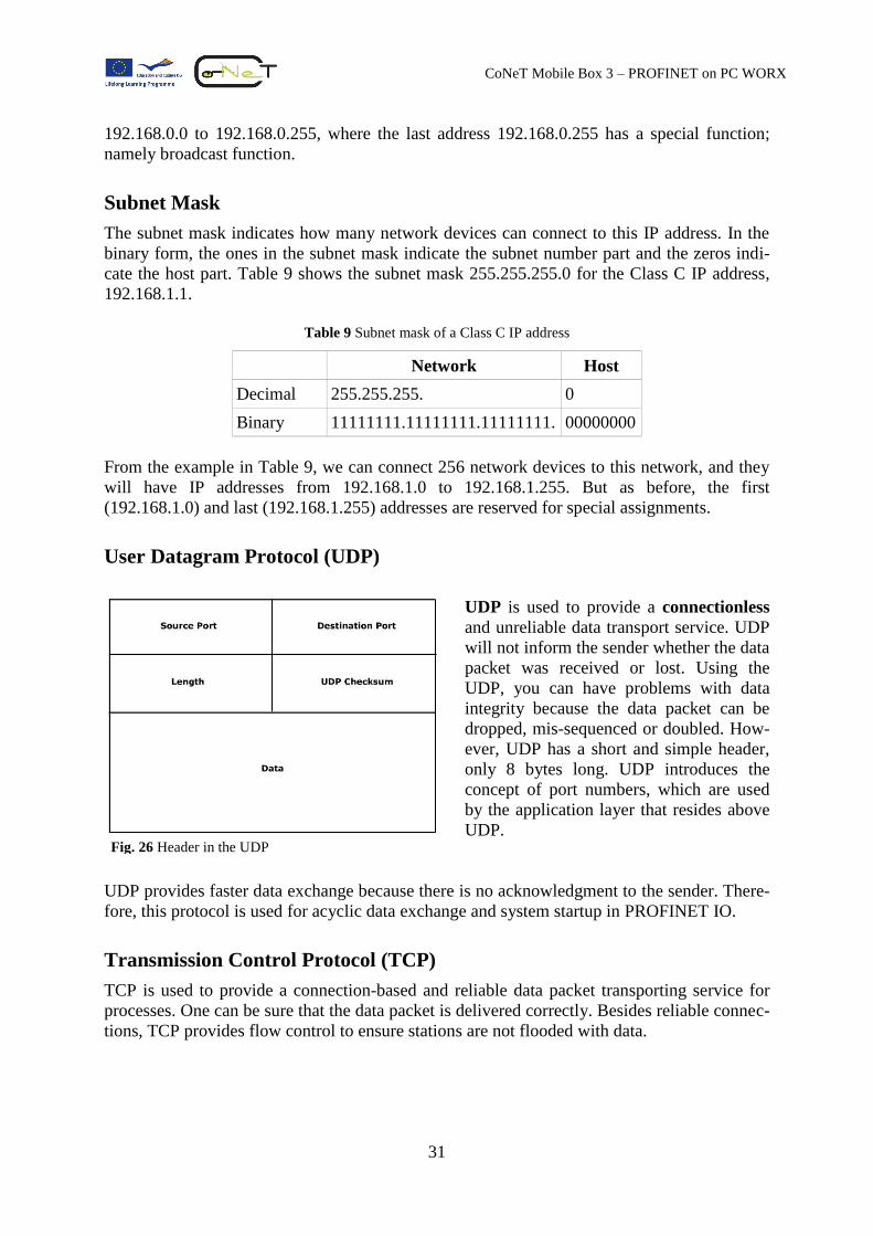
User Datagram Protocol (UDP)
UDP is used to provide a connectionless
and unreliable data transport service. UDP
will not inform the sender whether the data
packet was received or lost. Using the
UDP, you can have problems with data
integrity because the data packet can be
dropped, mis-sequenced or doubled. How-
ever, UDP has a short and simple header,
only 8 bytes long. UDP introduces the
concept of port numbers, which are used
by the application layer that resides above
UDP.
UDP provides faster data exchange because there is no acknowledgment to the sender. There-
fore, this protocol is used for acyclic data exchange and system startup in PROFINET IO.
Transmission Control Protocol (TCP)
TCP is used to provide a connection-based and reliable data packet transporting service for
processes. One can be sure that the data packet is delivered correctly. Besides reliable connec-
tions, TCP provides flow control to ensure stations are not flooded with data.
Fig. 26 Header in the UDP
32
CoNeT Mobile Box 3 – PROFINET on PC WORX
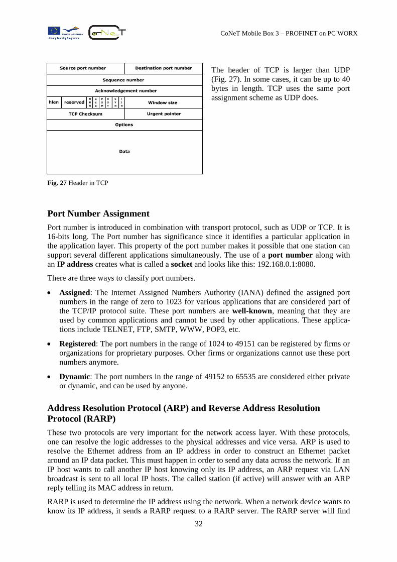
The header of TCP is larger than UDP
(Fig. 27). In some cases, it can be up to 40
bytes in length. TCP uses the same port
assignment scheme as UDP does.
Fig. 27 Header in TCP
Port Number Assignment
Port number is introduced in combination with transport protocol, such as UDP or TCP. It is
16-bits long. The Port number has significance since it identifies a particular application in
the application layer. This property of the port number makes it possible that one station can
support several different applications simultaneously. The use of a port number along with
an IP address creates what is called a socket and looks like this: 192.168.0.1:8080.
There are three ways to classify port numbers.
Assigned: The Internet Assigned Numbers Authority (IANA) defined the assigned port
numbers in the range of zero to 1023 for various applications that are considered part of
the TCP/IP protocol suite. These port numbers are well-known, meaning that they are
used by common applications and cannot be used by other applications. These applica-
tions include TELNET, FTP, SMTP, WWW, POP3, etc.
Registered: The port numbers in the range of 1024 to 49151 can be registered by firms or
organizations for proprietary purposes. Other firms or organizations cannot use these port
numbers anymore.
Dynamic: The port numbers in the range of 49152 to 65535 are considered either private
or dynamic, and can be used by anyone.
Address Resolution Protocol (ARP) and Reverse Address Resolution
Protocol (RARP)
These two protocols are very important for the network access layer. With these protocols,
one can resolve the logic addresses to the physical addresses and vice versa. ARP is used to
resolve the Ethernet address from an IP address in order to construct an Ethernet packet
around an IP data packet. This must happen in order to send any data across the network. If an
IP host wants to call another IP host knowing only its IP address, an ARP request via LAN
broadcast is sent to all local IP hosts. The called station (if active) will answer with an ARP
reply telling its MAC address in return.
RARP is used to determine the IP address using the network. When a network device wants to
know its IP address, it sends a RARP request to a RARP server. The RARP server will find
33
CoNeT Mobile Box 3 – PROFINET on PC WORX
the corresponding IP address in its configuration file and send this IP address back with a
RARP reply packet.
Other useful protocols
LLDP: Low Level Discovery Protocol is used to recognize its neighbor. Each station
sends its own information, such as MAC address, device name, etc. as a frame to the di-
rect neighbor.
DHCP: Dynamic Host Configuration Protocol is used for assignment of the IP addresses
and related parameters, if the corresponding infrastructure is available.
DNS: Domain Name Service is used in order to manage the logic names.
SNMP: Simple Network Management Protocol is used in order to monitor the network.
With this protocol, one can read out the status, statistical information and detect commu-
nication errors.
ICMP: Internet Control Message Protocol is used to forward error information.
Questions
What do we use as a common language for network devices?
1. Proxy
2. Gateway
3. Protocol
4. Message
What does the term “packet” describe in this case?
1. A chunk of protocol message
2. A chunk of IP data
3. A small box or part of a system
4. A small piece of a signal
The IP address 192.168.1.1 is a part of network class C.
1. True.
2. False
Which of the following statements is correct?
1. UDP is connectionless.
2. TCP is connectionless.
3. UDP provides data exchange faster than TCP.
4. TCP provides data exchange faster than UDP
5. 1 and 3 are correct
Which protocol can be used to recognize its neighbor?
1. SNMP
2. LLDP
3. ARP
4. ICMP
34
CoNeT Mobile Box 3 – PROFINET on PC WORX
Summary
PROFINET is an industrial communication system based on industrial Ethernet standard. It
builds on the well-known and highly popular PROFIBUS system. The main advantages of
PROFINET against PROFIBUS are high-speed data transfer, which is up to 100 Mbps, and
the possibility of obtaining the process data from the field devices. A positive side effect is
that you will have a continuous communication system from the office area to the automation
area. This will facilitate monitoring, improve engineering productivity and make management
easier. Please bear in mind that in the automation area the environmental conditions for the
devices can be extreme (dust, temperature, EMC, etc.). Therefore, the network devices must
be robust enough in order to function correctly.
PROFINET IO is designed for a data exchange system between controllers and field devices.
PROFINET CBA is designed for a distributed automation system. Both concepts are based on
using industrial Ethernet standard.
To understand the PROFINET, you took a look at the basics of Ethernet standard. We dis-
cussed the basic ideas behind the ISO/OSI reference model and the method of CSMA/CD
Ethernet concept. Furthermore, we explained the installation techniques for Ethernet and
PROFINET. The copper cables “twisted pair” are used widely now, but in the near future the
fiber optic cable will be more significant.
To enable network devices to “speak” with each other, they must speak the same languages,
the so-called protocols. We looked at several network protocols from the Internet protocol
family and at some network protocols which are useful for the PROFINET. The most impor-
tant protocols are IP, TCP, UDP, SNMP, etc.