conductivity sensor assemblies - southeastern...
TRANSCRIPT

��������� ��� ��Conductivity Sensor Assemblies
Instruction ManualPN 51-140/rev.CJune 2002

WARNING RETRACTABLE SENSORS
Retractable sensors must not be insertednor retracted when process pressuresare in excess of 100 psig (791 kPa).
CAUTIONSENSOR/PROCESS
APPLICATION COMPATIBILITYThe wetted sensor materials may not becompatible with process composition andoperating conditions. Application compat-ibility is entirely the responsibility of theuser.
DANGERHAZARDOUS AREA INSTALLATION
This sensor is not Intrinsically Safe orExplosion Proof. Installations near flamma-ble liquids or in hazardous area locationsmust be carefully evaluated by qualified onsite safety personnel.
To secure and maintain an intrinsically safeinstallation, an appropriate transmitter/ safetybarrier/sensor combination must be used.The installation system must be in accor-dance with the governing approval agency(FM, CSA or BASEEFA/CENELEC) haz-ardous area classification requirements.Consult your analyzer/transmitter instructionmanual for details.
Proper installation, operation and servicing ofthis sensor in a Hazardous Area Installationis entirely the responsibility of the user.
ESSENTIAL INSTRUCTIONSREAD THIS PAGE BEFORE PROCEEDING!
Rosemount Analytical designs, manufactures, and tests itsproducts to meet many national and international stan-dards. Because these instruments are sophisticated tech-nical products, you must properly install, use, and maintainthem to ensure they continue to operate within their normalspecifications. The following instructions must be adheredto and integrated into your safety program when installing,using, and maintaining Rosemount Analytical products.Failure to follow the proper instructions may cause any oneof the following situations to occur: Loss of life; personalinjury; property damage; damage to this instrument; andwarranty invalidation.
• Read all instructions prior to installing, operating, andservicing the product. If this Instruction Manual is not thecorrect manual, telephone 1-800-654-7768 and therequested manual will be provided. Save this InstructionManual for future reference.
• If you do not understand any of the instructions, contactyour Rosemount representative for clarification.
• Follow all warnings, cautions, and instructions marked onand supplied with the product.
• Inform and educate your personnel in the proper instal-lation, operation, and maintenance of the product.
• Install your equipment as specified in the InstallationInstructions of the appropriate Instruction Manual andper applicable local and national codes. Connect allproducts to the proper electrical and pressure sources.
• To ensure proper performance, use qualified personnelto install, operate, update, program, and maintain theproduct.
• When replacement parts are required, ensure that quali-fied people use replacement parts specified byRosemount. Unauthorized parts and procedures canaffect the product’s performance and place the safeoperation of your process at risk. Look alike substitutionsmay result in fire, electrical hazards, or improper opera-tion.
• Ensure that all equipment doors are closed and protec-tive covers are in place, except when maintenance isbeing performed by qualified persons, to prevent electri-cal shock and personal injury.
Emerson Process Management
Rosemount Analytical Inc.2400 Barranca ParkwayIrvine, CA 92606 USATel: (949) 757-8500Fax: (949) 474-7250
http://www.RAuniloc.com
© Rosemount Analytical Inc. 2001

MODEL 140, 141, 142 TABLE OF CONTENTS
MODEL 140, 141, 142CONDUCTIVITY SENSOR ASSEMBLIES
TABLE OF CONTENTSSection Title Page
1.0 INSTALLATION ....................................................................................................... 1
1.1 Receiving Inspection................................................................................................ 1
1.2 Mechanical Installation............................................................................................. 1
1.3 Electrical Installation ................................................................................................ 4
2.0 MAINTENANCE ...................................................................................................... 8
2.1 General .................................................................................................................... 8
2.2 Model 140 ................................................................................................................ 9
2.3 Model 141 ................................................................................................................ 12
2.4 Model 142 ................................................................................................................ 12
2.5 Troubleshooting ....................................................................................................... 12
3.0 DESCRIPTION AND SPECIFICATIONS................................................................. 13
3.1 Features and Applications ....................................................................................... 13
3.2 Ordering Information ................................................................................................ 17
4.0 RETURN OF MATERIAL......................................................................................... 18
4.1 General .................................................................................................................... 18
4.2 Warranty Repair ....................................................................................................... 18
4.3 Non Warranty Repair ............................................................................................... 18
i

MODEL 140, 141, 142 TABLE OF CONTENTS
LIST OF FIGURES
Figure No. Title Page
1-1 Sensor Orientation ................................................................................................... 1
1-2 Model 140 and Ball Valve Kit (PN 23724-00) Installation......................................... 2
1-3 Model 141 Installation .............................................................................................. 2
1-4 Model 142 Installation .............................................................................................. 3
1-5a Sensor-Mounted Junction Box................................................................................. 4
1-5b Wire Functions ......................................................................................................... 4
1-6 Sensor-Mounted Junction Box Wiring...................................................................... 4
1-7 Model 54C Wiring .................................................................................................... 4
1-8 Model 81C Wiring .................................................................................................... 4
1-9 Models 1054AC and 2054C Wiring.......................................................................... 5
1-10 Model 1054BC Wiring .............................................................................................. 5
1-11 Model 1054BDC and 1054BR Wiring ...................................................................... 5
1-12 Model 1054BLC Wiring ............................................................................................ 5
1-13 Model 1054C Wiring ................................................................................................ 5
1-14 Model 1181C Wiring................................................................................................. 6
1-15 Model 2081C Wiring ................................................................................................ 6
1-16 Models 3081C and 4081C Wiring ............................................................................ 6
1-17 Wiring 140-54,140-55, 140-56, 140-57, 141-54 & 142-54 to Model 1055-20-30 ..... 6
1-18 Model 1055-xx-10-20 (Single Contacting Conductivity Sensor) .............................. 7
1-19 Cable Preparation, Dual Coax (PN 9200275).......................................................... 7
2-1 Model 140 with Ball Valve Kit (PN 23724-00) .......................................................... 8
2-2 Sensor Continuity Check ......................................................................................... 10
3-1 Model 140 Mounting Dimensions............................................................................. 14
3-2 Model 141 Mounting Dimensions............................................................................. 15
3-3 Model 142 Mounting Dimensions............................................................................. 15
LIST OF TABLES
Table No. Title Page
1-1 Wiring Diagram Location.......................................................................................... 4
2-1 T.C. Element Temperature vs. Resistance............................................................... 9
3-1 Sensor Specifications .............................................................................................. 16
3-2 Model 141 & 142 Pressure Deration Graph............................................................. 16
ii

1
MODEL 140, 141, 142 SECTION 1.0INSTALLATION
SECTION 1.0INSTALLATION
1.2.2 Model 140 Sensor* Installation.The sensor is installed in either a 1-in. NPT weldaletor pipe tee (see Figure 1-2 for part nomenclature andinstallation information). **Install the sensor as follows:1. Make sure that the distance between the sensor
and analyzer/transmitter is within the limits speci-fied in the instrument instruction manual.
2. Remove plastic shipping cap from the tip of thesensor.
3. Install the 1-in. NPT hex nipple into the weldalet orTee as illustrated. (Figure 1-2). Use Teflon pipetape on the pipe threads.
4. Position the entire sensor for easy access to theball valve handle, sensor compression fitting nutand J-box terminal block.
5. Make sure the ball valve is in the fully open posi-tion.
6. Finger tighten the sensor compression fitting nut.Do not overtighten the sensor compression fittingnut because the next step is to press the sensorinto the process pipe.
7. Set the sensor tip no closer than 1 inch from the farwall of the process piping. (See Figure 1-2).
8. Tighten the sensor compression fitting nut to holdsensor tip in position. See Figure 1-2 for sensorcompression fitting tightening instructions.
* With Ball Valve Kit (PN 23724-00)** If installing a Model 140 sensor through a ball valve already in
place, refer to Section 2.2.5.
1.1 INSPECTION.Inspect the shipping container for damage. If damageis found, contact the carrier immediately. Inspect thesensor. Make sure all items on the packing list arepresent and in good condition. Notify the factory if partsare missing.
NOTESave the original packing carton andmaterials. Most carriers require proof ofdamage from mishandling. Use the origi-nal packing carton when returning thesensor to the factory. Refer to Section 4.0for instructions.
Improper installation and poor maintenance of the sen-sor are the major causes of measurement problems.The importance of careful adherence to the installationand maintenance instructions in this manual cannot beoveremphasized.
1.2 MECHANICAL INSTALLATION.1.2.1 Location Selection1. Select a location where the sample is representa-
tive of the process.2. Avoid dead ends or pipe stubs or any locations
where circulation may be poor.3. Ensure that the stream velocity at the point of
installation is not so great as to distort or damagethe sensor.
4. Where the stream velocity is low, mount the sensorso that the flow enters the end of the sensor andleaves through the vents in the side. This gives the greatest exchange of solution and the fastest response to conductivity changes.
5. Installing the sensor is a horizontal orientation isrecommended to prevent interference by air orsludge entrapment. Generally, vertical downwardmounting is not recommended due to air entrap-ment. Vertical upward mounting in the bottom ofthe pipe is also not recommended as it may allowthe cell to accumulate sediment (see Figure 1-1).
6. Mount the sensor so that the liquid contacts the sensor to the pipe threads.
FIGURE 1-1. Sensor Orientation

2
MODEL 140, 141, 142 SECTION 1.0INSTALLATION
1.2.3 Model 141 Sensor Installation. This sensor may be installed into a 3/4-in. NPT weldalet in the top or sideof a vessel or in a 1-in. NPT pipe Tee in a flowing process line.
Install Sensor as follows:1. Make sure that the distance between the sensor and analyzer/transmitter is within the limits specified in the
instrument instruction manual.
2. Remove the plastic shipping cap from the tip of the probe.
3. Install the Model 141 sensor into the 3/4-in. weldalet or pipe tee (See Figure 1-3). Use Teflon thread tape onthe pipe threads.
FIGURE 1-3. Model 141 Installation
DWG. NO. REV.
40014204 B
A
PROCESS PIPING
PUT WRENCH “A” HERE ANDTURNWRENCH “A”
WRENCH “B”
BALL VALVE
SENSOR COMPRESSIONFITTING
SENSOR
PUT WRENCH “B” HERE
SIDE VIEW
TOP VIEW
CAUTIONProcess O-Ringmust be in placeand is critical.Replace if wornor dirty.
Tighten finger tight beforeinserting sensor
Hold body with wrenchB and turn WRENCH A1 1/4 turns beyond fin-ger tight.
WELDALET1-in. NPT HEX NIPPLE
BALL VALVE
DWG. NO. REV.
40014008 E
FIGURE 1-2. Model 140 Installation with Ball Valve Kit (PN 23724-00)

3
MODEL 140, 141, 142 SECTION 1.0INSTALLATION
1.2.4 Model 142 Sensor Installation. This sensor may be installed in a 3/4-in. NPT weldalet in the top or side of a vessel or in a one-inch pipe Tee in aflowing process line. Install as follows:1. Make sure that the distance between the sensor and analyzer/transmitter is within the limits specified in the
instrument instruction manual.2 Remove the plastic shipping cap from the tip of the probe.3. Install sensor into the 3/4 inch weldalet or pipe Tee (See Figure 1-4). Use Teflon thread tape on the pipe
threads. DO NOT tighten the sensor compression fitting until the sensor is correctly positioned.4. Loosen sensor compression fitting and position sensor in Tee as illustrated in Figure 1-4. Tip of sensor must
be a minimum of one-inch from any opposing wall.5. Tighten sensor compression fitting in the same manner as illustrated for the Model 140 sensor compression
fitting (Figure 1-1).
FIGURE 1-4. Model 142 Installation
DWG. NO. REV.
40014204 B

MODEL 140, 141, 142 SECTION 1.0INSTALLATION
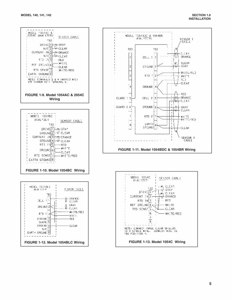
1.3 ELECTRICAL INSTALLATION.The following diagrams are for wiring Model 140 Series con-ductivity sensors to various instruments (see Table 1-1 tofind the appropriate wiring diagrams). Models 140, 141, and142 include a sensor-mounted junction box (see Figure 1-5a). Extension cable PN 9200275 (unprepped) or PN 23747-00 (prepped as shown in Figure 1-5b) must be ordered sep-arately for these models. See Figure 1-5b for wire functions.See Figure 1-6 for wiring extension cable to the terminalblock inside a sensor-mounted junction box. For example, towire a 140 sensor to a 54eC analyzer, connect one end ofthe extension cable to the sensor-mounted junction box(Figure 1-6) and the other end to the analyzer (Figure 1-7).After wiring, install the cover on the junction box making surethat the gasket is properly seated.The sensor is now ready for operation. Please refer to the ana-lyzer/transmitter manual for instrument calibration procedures.
For Wiring To See FigureSensor-mounted junction box 1-6
Model 54C and 54e C 1-7Model 81C 1-8
Model 1054AC 1-9Model 1054BC 1-10
Model 1054BDC 1-11Model 1054BLC 1-12Model 1054BR 1-11Model 1054C 1-13Model 1181C 1-14Model 2054C 1-9Model 2081C 1-15Model 3081C 1-16Model 4081C 1-16
Model 1055-20-30 1-17Model 1055-20 1-17
TABLE 1-1. Wiring Diagram Location
FIGURE 1-5b. Wire Functions
FIGURE 1-6. Sensor-MountedJunction Box Wiring
NOTE: TERMINALS IN JUNCTION BOX ARENOT NUMBERED.
OLD MODEL 140 SERIES SENSORS MAYNOT MATCH THE FIGURE.
MODEL 140 SENSORS HAVE TWOGRAY WIRES. BOTH CONNECTHERE.
GR
AY
GR
AY
**
FIGURE 1-7. Model 54C and54e C Wiring
MODEL 140 SERIES
4
FIGURE 1-8. Model 81C Wiring
NOTE: JUMPER SUPPLIED BY CUSTOMER.
FIGURE 1-5a. Sensor-Mounted Junction Box
MODEL 140, 141, 142 SECTION 1.0INSTALLATION
FIGURE 1-9. Model 1054AC & 2054CWiring
FIGURE 1-10. Model 1054BC Wiring
FIGURE 1-11. Model 1054BDC & 1054BR Wiring
FIGURE 1-12. Model 1054BLC Wiring
5
FIGURE 1-13. Model 1054C Wiring
MODEL 140, 141, 142 SECTION 1.0INSTALLATION
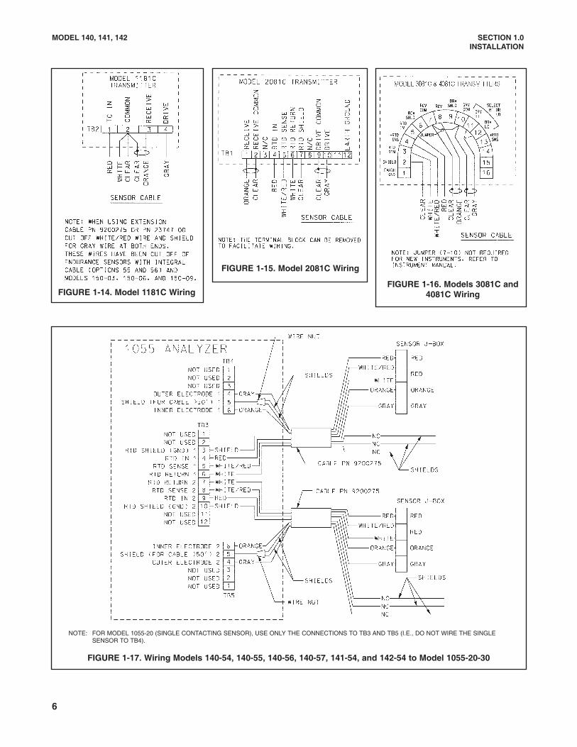
FIGURE 1-14. Model 1181C Wiring
FIGURE 1-15. Model 2081C Wiring
FIGURE 1-16. Models 3081C and4081C Wiring
FIGURE 1-17. Wiring Models 140-54, 140-55, 140-56, 140-57, 141-54, and 142-54 to Model 1055-20-30
6
NOTE: FOR MODEL 1055-20 (SINGLE CONTACTING SENSOR), USE ONLY THE CONNECTIONS TO TB3 AND TB5 (I.E., DO NOT WIRE THE SINGLE SENSOR TO TB4).

7
MODEL 140, 141, 142 SECTION 1.0INSTALLATION
FIGURE 1-19. Cable Preparation, Dual Coax (Part Number 9200275)
DWG. NO. REV.
40040022 A
FIGURE 1-18. Model 1055-xx-10-20 Wiring (Single Contacting Conductivity Sensor)

8
FIGURE 2-1. Model 140 with Ball Valve Kit (PN 23724-00)
MODEL 140, 141, 142 SECTION 2.0MAINTENANCE
SECTION 2.0MAINTENANCE
Viton O-ring (inside) (PN 9550200)
Compression Fitting Body
Peek Ferrule (inside)
Peek Split Ring (inside)
Sensor Compression Fitting Nut
Sensor Tube
DWG. NO. REV.
40014013 D
Ball Valve Kit(PN 23724-00)
(1-in. NPT Hex Nipple)
Included in Kit(PN 23730-00)
Flared Mechanical Stop
Nylon Ferrule (inside)
Junction Box
Junction Box Compression Fitting (PN9310120)
(Reducing Bushing)
Junction Box Cover
Note: Parentheses indicate these could be deleted. They are included in the ball valve kit (PN 23747-00). Figure 3-1 also shows theseparts.
2.1 GENERAL.
Rosemount Analytical recommends regular inspectionof in-service conductivity sensors. Conditions of serviceand the magnitude of the conductances being meas-ured will determine the frequency of inspection. In gen-eral the more conductive the liquid and the higher thelevel of suspended solids, the more often inspection isrequired. Any unusual behavior, not attributable toknown variations in the process, should be taken as anindication that the sensor requires maintenance.Periodic inspection should answer the following ques-tions: 1. Are there cracks or chips in the sensors or any
signs of wear? 2. Are the flow holes free from obstruction?
3. Is there indication that excessive streamvelocities have caused erosion or changes in the position of the electrodes?
4. Do the electrodes show signs of corrosion or deterioration?
5. Is the leakage resistance of the dry electrodes (measured between the drive and sense leads) at least 50 megohms?
6. Does the resistance across the temperature compensation wires match the temperature vs. resistance values in Table 2-1 (Section 2.2.1)?

9
TABLE 2-1. T.C. Element Temperature vs. Resistance
PT 100 T.C. Element1
TEMPERATURE RESISTANCE
0°C 100.00 ohms
10°C 103.90 ohms
20°C 107.70 ohms
25°C 109.62 ohms
30°C 111.67 ohms
40°C 115.54 ohms
50°C 119.40 ohms
60°C 123.24 ohms
70°C 127.07 ohms
80°C 130.89 ohms
90°C 134.70 ohms
100°C 138.50 ohms
110°C 142.29 ohms
120°C 146.06 ohms
130°C 149.82 ohms
140°C 153.58 ohms
150°C 157.31 ohms
160°C 161.04 ohms
170°C 164.76 ohms
180°C 168.46 ohms
190°C 172.16 ohms
200°C 175.84 ohms
TEMPERATURE RESISTANCE
0°C 29.49K
10°C 18.89K
20°C 12.26K
25°C 10.0K
30°C 8194 ohms
40°C 5592 ohms
50°C 3893 ohms
60°C 2760 ohms
70°C 1990 ohms
TEMPERATURE RESISTANCE
80°C 1458 ohms
90°C 1084 ohms
100°C 816.8 ohms
110°C 623.5 ohms
120°C 481.8 ohms
130°C 376.4 ohms
140°C 297.2 ohms
150°C 237.0 ohms
– –
TEMPERATURE RESISTANCE
0°C 371.4K
10°C 214.5K
20°C 128.0K
25°C 100.0K
30°C 78.7K
40°C 49.8K
50°C 32.4K
60°C 21.6K
70°C 13.8K
TEMPERATURE RESISTANCE
80°C 8.35K
90°C 6.45K
100°C 4.54K
110°C 3.24K
120°C 2.38K
130°C 1.78K
140°C 1.35K
150°C 1.01K
160°C 0.77K
1PT 100 used with standard and high temperature sensors.Compatible with Models 54C/1054A C/1054B C/1054B R and 2054C.
210K used with standard sensors. 100K used with high temperature sensors(Option 14). Both are compatible with Models 1181C, 733, and 750.
10K Ohm T.C. Element2
100K Ohm T.C. Element2
MODEL 140, 141, 142 SECTION 2.0MAINTENANCE
2.2 MODEL 140. Remove the sensor as follows:
WARNINGWhen retracting the sensor through a ballvalve, the system pressure must be lessthan 100 psig (791 kPa). System pres-sure may cause the sensor to retract withgreat force. Make sure the followingsteps are performed carefully.
1. Push in on the sensor J-box and slowly loosen thesensor compression fitting nut (reversing the sensortightening procedure illustrated in Figure 1-2).
2. When the sensor compression nut is completelyunscrewed, slowly ease the sensor out until theflared tip of the electrode rests firmly within thecompression fitting body.
3. Close the ball valve completely.
CAUTION
Before removing the sensor, make sure theball valve is fully closed.
4. Unscrew the compression fitting body from thereducing bushing and remove the sensor from theball valve assembly. The sensor may now be serv-iced.
2.2.1 Temperature Compensation Check. To insurethat the temperature compensation circuit is oper-ating correctly, perform the following check:
1. With the the instrument leads disconnected, con-nect an ohmmeter across the two red leads of thesensor.
2. The temperature in Table 2-1 should produce thecorresponding resistance readings. If processtemperature is not known, remove the sensor fromthe process. Have a thermometer next to theprobe tip to indicate the temperature.
3. If the temperature compensation element does notrespond accurately the sensor should be replaced.

10
MODEL 140, 141, 142 SECTION 2.0MAINTENANCE
FIGURE 2-2. Sensor Continuity Check
DWG. NO. REV.
40014006 J
2.2.2 Electrode Check. The sensor may be checkedfor electrode stability and operating condition by per-forming the following check:
1. With the sensor removed from the sensor system andinstrument leads disconnected, clean the tip of theprobe with a 10% solution of nitric acid or mild solvent.Rinse thoroughly with distilled or deionized water andthen dry completely.
2. Connect an ohmmeter across the black and whiteleads of the sensor.
3. With the probe dry and clean, the resistance shouldread from 10 megohms to an excess of 100megohms. The sensor will be operational with areading as low as 10 megohms, but its service lifemay not be long. It should be checked and the read-ing recorded weekly and. If the deterioration contin-ues, the sensor should be replaced.
4. Continuity Check: Measure resistance from TB1-4in the junction box and the outer electrode andfrom TB1 - 5 in the junction box and the inner elec-trode. Both should be zero ohms (see Figure 2-2).
NOTEMake sure the tip of the probe is dry; thereading can be affected by moisture.
2.2.3 Model 140 Retraction Restraint Check. Theintegrity of this system, will become compromised ifthe flared tip of the electrode is allowed to blowoutagainst the compression fitting body. In the event thata blowout occurs, replace the sensor with a newassembly. Parts may be ordered from RosemountAnalytical (see Section 3.2, for replacement parts andaccessories).

11
MODEL 140, 141, 142 SECTION 2.0MAINTENANCE
2.2.4 Process Seal Maintenance.If the process seal is leaking due to a pitted or unevensensor tube, a replacement sensor is required (seeSection 3.2, for replacement parts and accessories). Ifthe sensor tube surface is smooth and clean yet theprocess seal is leaking, the process O-ring is dam-aged and requires replacement according to the fol-lowing procedure (see Figure 2-1). Replacement partscan be obtained from the Process Fitting Rebuild Kit(PN 23731-00).1. The junction box with attached compression fitting
body, nut and compression fitting must be recoveredfrom the sensor for reuse. Unscrew the junction boxcover and set aside. Mark and disconnect the electri-cal connections from the terminal block. Remove thejunction box compression fitting nut from the compres-sion fitting body and separate the junction box from thesensor tube.
2. Remove the nylon ferrule and snap ring (discardboth). Remove and save the junction box com-pression fitting nut.
3. Slide off the sensor compression fitting nut and setaside for reuse. Slide off the remaining PEEK fer-rule and split ring (discard both).
4. Remove the sensor compression fitting body andreplace the Viton O-ring. Lubricate the O-ring withthe Barium based lubricant provided.
5. Cover the pipe threads of the sensor compressionfitting body with Teflon tape and slide it on to thesensor tube.
6. Slide on a new PEEK ferrule, beveled side facingthe electrode tip, and a new PEEK split ring, flaredend towards electrode tip. Slide on the sensorcompression fitting nut and thread it onto the com-pression fitting body. Finger tighten.
7. Reinstall the J-box on the sensor tube. Fingertighten the J-box compression fitting nut. Use awrench to turn the nut a 1/4 to 1/2 additional turn.
2.2.5 Sensor Insertion.
Insert the sensor into the ball valve as follows:
CAUTIONMake sure process O-ring is clean,lubricated, and in place beforeinstalling sensor. Replace if worn.
1. DO NOT open the ball valve.
WARNINGThe system pressure must be lessthan 100 psig (791 kPa).
2. Thread the sensor compression fitting body intothe reducing bushing in the rear of the ball valveand tighten.
NOTEDo not push past this point. Damageto the sensor could result.
WARNINGIf the sensor comes free of thevalve, refer to Figure 2-1 and verifythat the valve and associated fit-tings are as shown. Do not proceeduntil the sensor is correctlyrestrained.
3. Slowly open the valve.
WARNINGStand clear of the sensor.
4. Insert the sensor up to the desired insertion depthand turn the sensor compression fitting nut until it isfinger tight.
5. Position the entire sensor for easy access to theball valve handle, sensor compression fitting nutand J-box terminal block.
6. Tighten sensor compression fitting nut.
CAUTIONFor initial installation of the sensor,tighten the compression fitting nut 1-1/4 turns after finger tight. If it is a rein-stallation, turn no more than 1/4 to 1/2additional turns!

12
MODEL 140, 141, 142 SECTION 2.0MAINTENANCE
2.3 MODEL 141.
Make sure the system pressure is shut off and removethe sensor as follows:
WARNING
Process flow or pressure must not bepresent.
1. Unscrew the sensor at the pipe fitting or weldalet.
2. Make sure the tip of the probe is dry; the readingcan be affected by moisture.
3. Check the temperature compensation element asinstructed in Section 2.2.1.
4. Check the electrodes as instructed in Section2.2.2, steps 2-4.
5. Install the sensor into process fitting. Use Teflontape on the pipe threads.
2.4 MODEL 142.
Make sure the system pressure is shut down andremove the sensor as follows:
WARNING
Process flow or pressure must not bepresent.
1. Loosen the process fitting and slowly slide thesensor from the pipe fitting or weldalet.
2. Check the temperature compensation element asinstructed in Section 2.2.1.
3. Check the electrodes as instructed in Section2.2.2, steps 2-4.
4. Install the sensor by sliding the probe into processfitting and position the probe as in the originalinstallation.
CAUTION
Make sure the probe is in the same posi-tion as originally installed. The probe takesa permanent set and could be weakened ifset is adjacent to original set.
5. Tighten sensor compression fitting nut 1/4 to 1/2turn after finger tight.
2.5 TROUBLESHOOTING.
Following the instructions under maintenance shouldkeep the sensor in good operating condition.
If, however, a problem should arise, consult the instru-ment or transmitter manual for explanation of diag-nostic errors. Rosemount analyzers and transmitters(except the Model 1181C) have a diagnostic featurethat automatically searches for fault conditions thatcause errors in the measured conductivity. If more thanone fault exists, the display sequences through all thediagnostic messages.
13
MODEL 140, 141, 142 SECTION 3.0DESCRIPTION AND SPECIFICATIONS
SECTION 3.0DESCRIPTION AND SPECIFICATIONS
3.1 FEATURES AND APPLICATIONS.
The Rosemount Analytical Model 140, 141, and 142conductivity sensors are designed for measuring con-ductivity in high temperature and pressure applica-tions. A choice of cell constants allows measurementsin low to medium conductivity level samples. The sen-sors’ corrosion-resistant 316 stainless steel construc-tion and ability to be inserted directly into a processline or through the side of a vessel make them ruggedand easy to install and maintain.
The Model 140 retractable conductivity sensor simpli-fies sensor installation and maintenance because itcan be removed from a pressurized line or vesselwithout shutting down the process or using bypasssample lines. The sensor’s measuring electrodes areinserted into process through a 1 inch ball valve and aViton1 process seal. To retract the sensor, a retainingnut is loosened, the sensor backed out of the processand the ball valve closed.
The standard Model 140 is constructed of 316 stainlesssteel and PEEK and can operate up to 150°C. Hightemperature options (Codes 05, 07, 55, or 57) must beselected to measure up to 200°C. The choice of a 0.2or 1.0 cell constant allows conductivity measurementsup to 20,000 µS/cm with the Rosemount AnalyticalModel 54eC, 1055, 1054B C, 1054B R, 1181C and2081C, 3081C, and 81C analyzers.
• HIGH TEMPERATURE 316 SS AND PEEK CONSTRUCTION operates up to 200°C(392°F).
• MODEL 140 RETRACTABLE SENSOR installs through a one-inch ball valve.
• INCLUDES ALL INSTALLATION HARDWARE.
• RUGGED CAST ALUMINUM WEATHER PROOF JUNCTION BOX provides easy accessto field wiring.
• MEASUREMENT RANGES FROM 0-1 µS/cm to 0-20,000 µS/cm.
1 A registered trademark of E. I. du Pont de Nemours and Company.2 A registered trademark of 3M Company.
The Model 141 Insertion Sensor measures conductiv-ity in high temperature, high pressure applications.The standard Model 141 is constructed of 316 stain-less steel and PEEK and can operate at temperaturesup to 150°C. An optional high temperature version(Code 14) can operate at temperatures up to 200°C.The choice of a 0.2 or 1.0 cell constant allows con-ductivity measurements up to 20,000 µS/cm with theRosemount Analytical Model 54eC, 1055, 1054B C,1054B DC, 1054B R, 1181C, 2081C, 3081C, and 81Canalyzers.
The Model 142 low conductivity insertion sensormeasures low conductivity solutions at high tempera-tures and pressures. The standard Model 142 is con-structed of 316 stainless steel and Kel-F2, and canoperate at temperatures up to 150°C. An optional hightemperature version (Code 14) can operate at temper-atures up to 200°C and is constructed to 316 stainlesssteel and PEEK. The choice of a 0.01 or 0.1 cell con-stant allows measurement ranges from 0-1 µS/cm andup to 0-2,000 µS/cm with the Rosemount AnalyticalModel 54eC, 1054B C, 1054B DC, 1054B R, 1055,2054C, 1181C, 2081C, 3081C, and 81C analyzers.

14
MODEL 140, 141, 142 SECTION 3.0DESCRIPTION AND SPECIFICATIONS
FIGURE 3-1. Model 140 Mounting Dimensions
WHEN INCH AND METRIC DIMSARE GIVEN
MILLIMETERINCH
DWG. NO. REV.
40014011 J

MODEL 140, 141, 142 SECTION 3.0DESCRIPTION AND SPECIFICATIONS
MILLIMETERINCH
DWG. NO. REV.
40014201 N
FIGURE 3-3. Model 142 Mounting Dimensions
MILLIMETERINCH
DWG. NO. REV.
40014101 U
FIGURE 3-2. Model 141 Mounting Dimensions
15

16
MODEL 140, 141, 142 SECTION 3.0DESCRIPTION AND SPECIFICATIONS
SPECIFICATIONS MODEL 140 MODEL 141 MODEL 142Cell Constant 0.2 and 1.0/cm 0.2 and 1.0/cm 0.01 and 0.1/cm
Standard: 150°C (302 °F) Standard: 150°C (302 °F) Standard: 150°C (302 °F)Maximum @ 250 psig (1825 KPa) @ 250 psig (1825 KPa)Temperature High Temp: 200°C (392°F) High Temp: 200°C (392°F) High Temp: 200°C (392°F)
@ 250 psig (1825 KPa) @ 250 psig (1825 KPa)
Maximum Pressure 100 psig (791 kPa) See Table 3-2 below See Table 3-2 below
Codes 04, 06, 54, 56: 0 to 150°C Standard: 0 to 150°C Standard: 0 to 150°CCompensation (32 to 302°F) (32 to 302°F) (32 to 302°F)Temperature Codes 05, 07, 55, 57: 100 to 200°C High Temp: 100 to 200°C High Temp: 100 to 200°C
(212 to 392°F) (212 to 392°F) (212 to 392°F)
WETTED MATERIALSElectrodes and 316 Stainless Steel. 316 Stainless Steel. 316 Stainless Steel. Insulators PEEK PEEK Kel-F1 for standard temp.
PEEK for high temp.
O-Rings Viton2 Viton2 Viton2
Sensor Body 316 Stainless Steel 316 Stainless Steel 316 Stainless Steel
Junction Box Cast Aluminum Cast Aluminum Cast Aluminum
Weight/Ship Weight w/ball valve 5 lb/6 lb (2.26/2.72 kg) 2 lb/3 lb (0.9/1.4 kg) 4 lbs/5 lb (1.9/2.3 kg)
1 A registered trademark of 3M Company.2 A registered trademark of E. I. du Pont de Nemours and Company
TABLE 3-1. SENSOR SPECIFICATIONS
TABLE 3-2. Models 141 and 142 Maximum Pressure

17
MODEL 140, 141, 142 SECTION 3.0DESCRIPTION AND SPECIFICATIONS
The Model 141/142 Insertion Conductivity Sensor: Designed for high pressure, high temperature service. The Model 141 Sensorcell constants of 0.2 and 1.0 are suitable for measurements up to 20,000 microsiemens/cm. The Model 142 Sensor cell constants of0.1 and 0.01 provide low level conductivity measurements. The sensors are constructed to operate up to 150°C. To operate between100°C and 200°C, the high temperature option (Code 14) must be selected. The sensors do not come with interconnecting cable.The cable must be ordered separately.
MODEL141/142 INSERTION CONDUCTIVITY SENSOR
CODE CELL CONSTANT (Required Selection)
01 0.01/cm (Model 142 only)
03 0.1/cm (Model 142 only)
04 0.2/cm (Model 141 only)
06 1.0/cm (Model 141 only)
141 06 13 54 EXAMPLE
CODE TEMPERATURE (Required Selection)
13 Standard construction for operation up to 150°C, 10K Ohm thermistor
*14* High temperature construction for operation between 100°C and 200°C, 100K Ohm thermistor
54 For use with Model 54eC, 1055, 1054B C, 1054B R, 2081C, 3081C, and 4081C (Pt 100 RTD replaces thermistor)
*Model 1181C must be supplied with 100° to 200°C temperature compensation range. Instrument must have compatible T.C. circuit.
PART # DESCRIPTION23724-00 Ball valve kit 316 stainless steel (2 lb/1 Kg)*9200104 Cable, 8 conductor, 24 AWG, 4 shielded pair (1181C) - specify length9200266 Cable, 9 conductor (54C, 2081C, 1054AC/2054C) - specify length9200275 Cable, 5 conductor, shielded (unprepped) - specify length23747-00 Cable, 5 conductor, shielded (prepped) - specify length9210004 Conductivity standard 2,000 Microsiemen/cm, 16 oz23730-00 Process compression fitting (3/4-in. NPT) kit (for Model 140 sensors)23731-00 Process fitting rebuild kit (for Model 140 sensors)9310120 Junction box compression fitting (for Model 140 sensors)9550200 O-ring, 2-116, Viton (for Model 140 sensors)3001882 Process compression fitting, 3/4-in. NPT (for Model 142 sensors)
ACCESSORIES
3.2 ORDERING INFORMATION.The Model 140 Retractable Conductivity Sensor: Designed for insertion through a one inch ball valve. Materials of constructioninclude 316 SS electrodes with a PEEK insulator for service up to 200°C. Standard features include a cast aluminum NEMA 7D junc-tion box, and a choice of cell constants of either 0.2 or 1.0.
MODEL140 RETRACTABLE CONDUCTIVITY SENSOR (6 lbs./2.7 kg)
140 04 54 EXAMPLE
CODE GROUP II FOR USE WITH MODEL 54eC, 1055, 1054B C, 1054B R, 2081C, 3081, 4081C
54 0.2 cell constant, Pt100 RTD
55 0.2 cell constant, high temperature construction, Pt100 RTD
56 1.0 cell constant, Pt100 RTD
57 1.0 cell constant, high temperature construction, Pt100 RTD
NOTES: *Instrument must be supplied with 100°-200°C temperature compensation range.1 Registered Trademark of 3M Company.
CODE GROUP I FOR USE WITH MODELS 1181C (Required selection - one only from Group I or II)
04 0.2 cell constant, 10K Ohm thermistor
*05* 0.2 cell constant, high temperature construction, 100K Ohm thermistor
06 1.0 cell constant, 10K Ohm thermistor
*07* 1.0 cell constant, high temperature construction, 100K Ohm thermistor
18
MODEL 140, 141, 142 SECTION 4.0RETURN OF MATERIAL
SECTION 4.0RETURN OF MATERIAL
4.1 GENERAL. To expedite the repair and return ofinstruments, proper communication between the cus-tomer and the factory is important. A return materialauthorization number is required. Call 1-800-654-7768 or 1-949-757-8500. Please enclose a Letter ofTransmittal detailing the need for the return.
4.2 WARRANTY REPAIR. The following is the proce-dure for returning products still under warranty.
1. Contact the factory for authorization.
2. To verify warranty, supply the factory sales ordernumber or the original purchase order number. Inthe case of individual parts or sub-assemblies, theserial number on the mother unit must be sup-plied.
3. Carefully package the materials and enclose your“Letter of Transmittal”. If possible, pack the mate-rials in the same manner as it was received.
IMPORTANTCompliance to the OSHA requirements ismandatory for the safety of all personnel.MSDS forms and a certification that theinstruments have been disinfected ordetoxified are required.
4. Send the package prepaid to:
Rosemount Analytical Inc.Uniloc Division2400 Barranca ParkwayIrvine, CA 92606
Attn: Factory Repair
Mark the package: Returned for Repair
RMA # ________________
Model No. _____________
4.3 NON WARRANTY REPAIR.
1. Contact the factory for authorization.
2. Enclose a Letter of Transmittal detailing the needfor the return.
3. Include a purchase order number and make sureto include the name and telephone number of theright individual to be contacted should additionalinformation be needed.
4. Do Steps 3 and 4 of Section 5.2.
NOTEConsult the factory for additional infor-mation regarding service or repair.

WARRANTYSeller warrants that the firmware will execute the programming instructions provided by Seller, and that the Goods manufacturedor Services provided by Seller will be free from defects in materials or workmanship under normal use and care until the expira-tion of the applicable warranty period. Goods are warranted for twelve (12) months from the date of initial installation or eighteen(18) months from the date of shipment by Seller, whichever period expires first. Consumables, such as glass electrodes,membranes, liquid junctions, electrolyte, o-rings, catalytic beads, etc., and Services are warranted for a period of 90days from the date of shipment or provision. Products purchased by Seller from a third party for resale to Buyer ("Resale Products") shall carry only the warranty extended bythe original manufacturer. Buyer agrees that Seller has no liability for Resale Products beyond making a reasonable commercialeffort to arrange for procurement and shipping of the Resale Products. If Buyer discovers any warranty defects and notifies Seller thereof in writing during the applicable warranty period, Seller shall, atits option, promptly correct any errors that are found by Seller in the firmware or Services, or repair or replace F.O.B. point of man-ufacture that portion of the Goods or firmware found by Seller to be defective, or refund the purchase price of the defective por-tion of the Goods/Services. All replacements or repairs necessitated by inadequate maintenance, normal wear and usage, unsuitable power sources, unsuit-able environmental conditions, accident, misuse, improper installation, modification, repair, storage or handling, or any othercause not the fault of Seller are not covered by this limited warranty, and shall be at Buyer's expense. Seller shall not be obligat-ed to pay any costs or charges incurred by Buyer or any other party except as may be agreed upon in writing in advance by anauthorized Seller representative. All costs of dismantling, reinstallation and freight and the time and expenses of Seller's person-nel for site travel and diagnosis under this warranty clause shall be borne by Buyer unless accepted in writing by Seller. Goods repaired and parts replaced during the warranty period shall be in warranty for the remainder of the original warranty peri-od or ninety (90) days, whichever is longer. This limited warranty is the only warranty made by Seller and can be amended onlyin a writing signed by an authorized representative of Seller. Except as otherwise expressly provided in the Agreement, THEREARE NO REPRESENTATIONS OR WARRANTIES OF ANY KIND, EXPRESS OR IMPLIED, AS TO MERCHANTABILITY, FIT-NESS FOR PARTICULAR PURPOSE, OR ANY OTHER MATTER WITH RESPECT TO ANY OF THE GOODS OR SERVICES.
RETURN OF MATERIAL
Material returned for repair, whether in or out of warranty, should be shipped prepaid to:
Emerson Process ManagementLiquid Division
2400 Barranca ParkwayIrvine, CA 92606
The shipping container should be marked:Return for RepairModel _______________________________
The returned material should be accompanied by a letter of transmittal which should include the following information (make acopy of the "Return of Materials Request" found on the last page of the Manual and provide the following thereon):
1. Location type of service, and length of time of service of the device.2. Description of the faulty operation of the device and the circumstances of the failure.3. Name and telephone number of the person to contact if there are questions about the returned material.4. Statement as to whether warranty or non-warranty service is requested.5. Complete shipping instructions for return of the material.
Adherence to these procedures will expedite handling of the returned material and will prevent unnecessary additional chargesfor inspection and testing to determine the problem with the device.
If the material is returned for out-of-warranty repairs, a purchase order for repairs should be enclosed.

Credit Cards for U.S. Purchases Only.
The right people,the right answers,right now. ON-LINE ORDERING NOW AVAILABLE ON OUR WEB SITE
http://www.raihome.com
Specifications subject to change without notice.
Emerson Process Management
Liquid Division2400 Barranca Parkway
Irvine, CA 92606 USA
Tel: (949) 757-8500
Fax: (949) 474-7250
http://www.raihome.com
© Rosemount Analytical Inc. 2005