conductive polymer aluminum p9 guidelines and ... - panasonic · "guidelines and precautions...
TRANSCRIPT
7 8
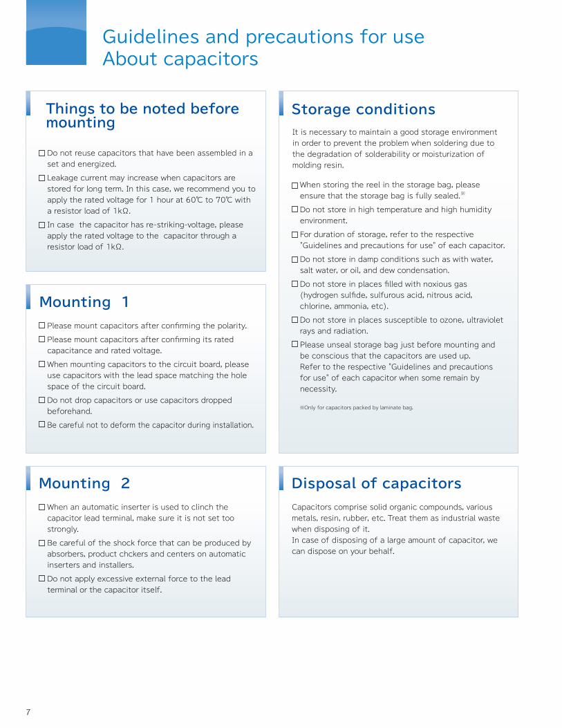
Guidelines and precautions for useAbout capacitors
Storage conditions
※Only for capacitors packed by laminate bag.
Disposal of capacitorsCapacitors comprise solid organic compounds, various metals, resin, rubber, etc. Treat them as industrial wastewhen disposing of it.In case of disposing of a large amount of capacitor, we can dispose on your behalf.
It is necessary to maintain a good storage environment in order to prevent the problem when soldering due to the degradation of solderability or moisturization of molding resin.
When storing the reel in the storage bag, please ensure that the storage bag is fully sealed.※
Do not store in high temperature and high humidity environment.
For duration of storage, refer to the respective "Guidelines and precautions for use" of each capacitor.
Do not store in damp conditions such as with water, salt water, or oil, and dew condensation.
Do not store in places filled with noxious gas (hydrogen sulfide, sulfurous acid, nitrous acid, chlorine, ammonia, etc).
Do not store in places susceptible to ozone, ultraviolet rays and radiation.
Please unseal storage bag just before mounting and be conscious that the capacitors are used up.Refer to the respective "Guidelines and precautions for use" of each capacitor when some remain by necessity.
Mounting 1Please mount capacitors after confirming the polarity.
Please mount capacitors after confirming its rated capacitance and rated voltage.
When mounting capacitors to the circuit board, please use capacitors with the lead space matching the hole space of the circuit board.
Do not drop capacitors or use capacitors dropped beforehand.
Be careful not to deform the capacitor during installation.
Mounting 2When an automatic inserter is used to clinch the capacitor lead terminal, make sure it is not set too strongly.
Be careful of the shock force that can be produced by absorbers, product chckers and centers on automatic inserters and installers.
Do not apply excessive external force to the lead terminal or the capacitor itself.
P8
P9
P11
P15
P25
P33
P61
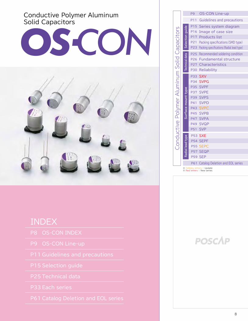
OS-CON INDEX
OS-CON Line-up
Guidelines and precautions
Selection guide
Technical data
Each series
Catalog Deletion and EOL series
Conductive Polymer Aluminum Solid Capacitors
INDEX
※ Yelloew letters : Update※ Red letters : New series
Things to be noted before mounting
Do not reuse capacitors that have been assembled in a set and energized.
Leakage current may increase when capacitors are stored for long term. In this case, we recommend you to apply the rated voltage for 1 hour at 60℃ to 70℃ with a resistor load of 1kΩ.
In case the capacitor has re-striking-voltage, please apply the rated voltage to the capacitor through a resistor load of 1kΩ.
Selection guide
Technical data
Radial lead type
OS-CON Line-up
Guidelines and precautions
Series system diagramImage of case sizeProducts listPacking specifications(SMD type)Packing specifications(Radial lead type)Recommended soldering conditionFundamental structureCharacteristicsReliability
SXVSVPGSVPFSVPESVPSSVPDSVPCSVPBSVPASVQPSVP
SXESEPFSEPCSEQPSEP
P9
P11
P15P16P17P21P23
P25P26P27P30
P33P34P35P37P39P41P43P45P47P49P51
P53P54P55P57P59
Catalog Deletion and EOL seriesP61
Surface mount type
Conductive Polymer Aluminum Solid Capacitors

65
Please take note of the following points in order to make the best use of capacitor's performance.Please use capacitors within the range of specified performance after confirming each capacitor's usage environment and circuit condition. Please choose capacitors that match the lifetime of the intended circuit design.The performance of capacitors is changed by the temperature or frequency. Therefore, please consider these variations when designing the circuit.Please buy capacitors from our official distributors. Otherwise there is no warranty.
Line-upConductive Polymer Aluminum Solid CapacitorsConductive Polymer Tantalum Solid Capacitors
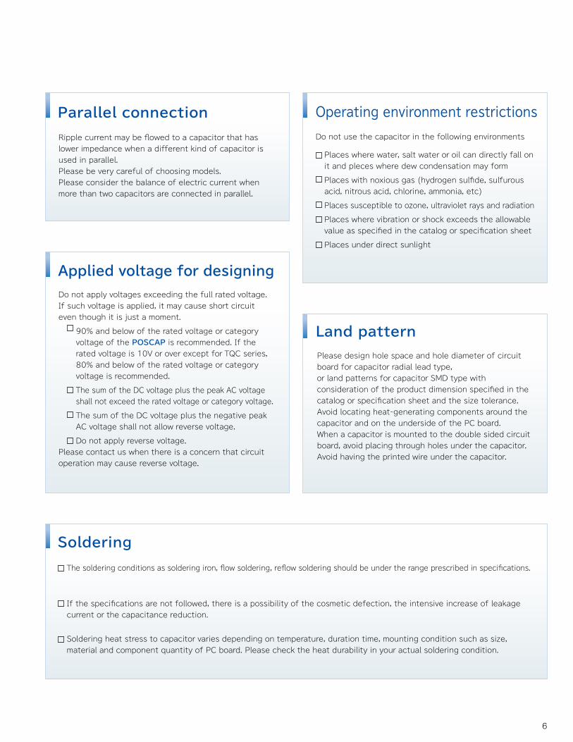
Do not apply voltages exceeding the full rated voltage. If such voltage is applied, it may cause short circuit even though it is just a moment.
90% and below of the rated voltage or category voltage of the POSCAP is recommended. If the rated voltage is 10V or over except for TQC series, 80% and below of the rated voltage or category voltage is recommended.
The sum of the DC voltage plus the peak AC voltage shall not exceed the rated voltage or category voltage.
The sum of the DC voltage plus the negative peak AC voltage shall not allow reverse voltage.
Do not apply reverse voltage.Please contact us when there is a concern that circuit operation may cause reverse voltage.
Applied voltage for designing
OS-CON and POSCAP have polarity.Please confirm the polarity prior to use. If it is used with the reverse polarities, leakage current, shorter lifetime or a short circuit may result.There is no bi-polar model of the OS-CON and POSCAP.
Polarity
Rating and category
Operating temperature and ripple current
Do not use the capacitor in the following environments
Operating environment restrictions
The definition of rating and category is as follows.
Rated temperature:The maximum ambient temperature at which rated voltage may be continuously applied.
Rated voltage:The maximum direct voltage or peak value of pulse voltage which may be applied continuously to a capacitor at any temperature between the lower category temperature and the rated temperature.
Category temperature range:The range of ambient temperatures for which a capacitor has been designed to operate continuously; this is given by the lower and upper category temperature.
Category voltage:The maximum voltage which may be applied continuously to a capacitor at its upper limit of category temperature.
Places where water, salt water or oil can directly fall on it and pleces where dew condensation may form
Places with noxious gas (hydrogen sulfide, sulfurous acid, nitrous acid, chlorine, ammonia, etc)
Places susceptible to ozone, ultraviolet rays and radiation
Places where vibration or shock exceeds the allowable value as specified in the catalog or specification sheet
Places under direct sunlight
The soldering conditions as soldering iron, flow soldering, reflow soldering should be under the range prescribed in specifications.
If the specifications are not followed, there is a possibility of the cosmetic defection, the intensive increase of leakage current or the capacitance reduction.
Soldering heat stress to capacitor varies depending on temperature, duration time, mounting condition such as size, material and component quantity of PC board. Please check the heat durability in your actual soldering condition.
SolderingSet the operating temperature so that it falls within the range stipulated in this delivery specification.
Do not apply current that exceeds the allowable ripple current. When excessive ripple current is applied, internal heat increases and reduces the lifetime.
In case capacitors are used under the condition out of the specified frequency, ripple current shall not exceed the value revised by the frequency coefficient.
Ripple current may be flowed to a capacitor that has lower impedance when a different kind of capacitor is used in parallel.Please be very careful of choosing models.Please consider the balance of electric current when more than two capacitors are connected in parallel.
Parallel connection
Land patternPlease design hole space and hole diameter of circuit board for capacitor radial lead type, or land patterns for capacitor SMD type with consideration of the product dimension specified in the catalog or specification sheet and the size tolerance.Avoid locating heat-generating components around the capacitor and on the underside of the PC board.When a capacitor is mounted to the double sided circuit board, avoid placing through holes under the capacitor.Avoid having the printed wire under the capacitor.
Considerations when using in industrial equipment
To when capacitors are used in industrial equipment, allow wider margin of capacitance, impedance and other characteristics.
Guidelines and precautions for useAbout capacitors
65
Please take note of the following points in order to make the best use of capacitor's performance.Please use capacitors within the range of specified performance after confirming each capacitor's usage environment and circuit condition. Please choose capacitors that match the lifetime of the intended circuit design.The performance of capacitors is changed by the temperature or frequency. Therefore, please consider these variations when designing the circuit.Please buy capacitors from our official distributors. Otherwise there is no warranty.
Line-upConductive Polymer Aluminum Solid CapacitorsConductive Polymer Tantalum Solid Capacitors
Do not apply voltages exceeding the full rated voltage. If such voltage is applied, it may cause short circuit even though it is just a moment.
90% and below of the rated voltage or category voltage of the POSCAP is recommended. If the rated voltage is 10V or over except for TQC series, 80% and below of the rated voltage or category voltage is recommended.
The sum of the DC voltage plus the peak AC voltage shall not exceed the rated voltage or category voltage.
The sum of the DC voltage plus the negative peak AC voltage shall not allow reverse voltage.
Do not apply reverse voltage.Please contact us when there is a concern that circuit operation may cause reverse voltage.
Applied voltage for designing
OS-CON and POSCAP have polarity.Please confirm the polarity prior to use. If it is used with the reverse polarities, leakage current, shorter lifetime or a short circuit may result.There is no bi-polar model of the OS-CON and POSCAP.
Polarity
Rating and category
Operating temperature and ripple current
Do not use the capacitor in the following environments
Operating environment restrictions
The definition of rating and category is as follows.
Rated temperature:The maximum ambient temperature at which rated voltage may be continuously applied.
Rated voltage:The maximum direct voltage or peak value of pulse voltage which may be applied continuously to a capacitor at any temperature between the lower category temperature and the rated temperature.
Category temperature range:The range of ambient temperatures for which a capacitor has been designed to operate continuously; this is given by the lower and upper category temperature.
Category voltage:The maximum voltage which may be applied continuously to a capacitor at its upper limit of category temperature.
Places where water, salt water or oil can directly fall on it and pleces where dew condensation may form
Places with noxious gas (hydrogen sulfide, sulfurous acid, nitrous acid, chlorine, ammonia, etc)
Places susceptible to ozone, ultraviolet rays and radiation
Places where vibration or shock exceeds the allowable value as specified in the catalog or specification sheet
Places under direct sunlight
The soldering conditions as soldering iron, flow soldering, reflow soldering should be under the range prescribed in specifications.
If the specifications are not followed, there is a possibility of the cosmetic defection, the intensive increase of leakage current or the capacitance reduction.
Soldering heat stress to capacitor varies depending on temperature, duration time, mounting condition such as size, material and component quantity of PC board. Please check the heat durability in your actual soldering condition.
SolderingSet the operating temperature so that it falls within the range stipulated in this delivery specification.
Do not apply current that exceeds the allowable ripple current. When excessive ripple current is applied, internal heat increases and reduces the lifetime.
In case capacitors are used under the condition out of the specified frequency, ripple current shall not exceed the value revised by the frequency coefficient.
Ripple current may be flowed to a capacitor that has lower impedance when a different kind of capacitor is used in parallel.Please be very careful of choosing models.Please consider the balance of electric current when more than two capacitors are connected in parallel.
Parallel connection
Land patternPlease design hole space and hole diameter of circuit board for capacitor radial lead type, or land patterns for capacitor SMD type with consideration of the product dimension specified in the catalog or specification sheet and the size tolerance.Avoid locating heat-generating components around the capacitor and on the underside of the PC board.When a capacitor is mounted to the double sided circuit board, avoid placing through holes under the capacitor.Avoid having the printed wire under the capacitor.
Considerations when using in industrial equipment
To when capacitors are used in industrial equipment, allow wider margin of capacitance, impedance and other characteristics.
Guidelines and precautions for useAbout capacitors
7 8
Guidelines and precautions for useAbout capacitors
Storage conditions
※Only for capacitors packed by laminate bag.
Disposal of capacitorsCapacitors comprise solid organic compounds, various metals, resin, rubber, etc. Treat them as industrial wastewhen disposing of it.In case of disposing of a large amount of capacitor, we can dispose on your behalf.
It is necessary to maintain a good storage environment in order to prevent the problem when soldering due to the degradation of solderability or moisturization of molding resin.
When storing the reel in the storage bag, please ensure that the storage bag is fully sealed.※
Do not store in high temperature and high humidity environment.
For duration of storage, refer to the respective "Guidelines and precautions for use" of each capacitor.
Do not store in damp conditions such as with water, salt water, or oil, and dew condensation.
Do not store in places filled with noxious gas (hydrogen sulfide, sulfurous acid, nitrous acid, chlorine, ammonia, etc).
Do not store in places susceptible to ozone, ultraviolet rays and radiation.
Please unseal storage bag just before mounting and be conscious that the capacitors are used up.Refer to the respective "Guidelines and precautions for use" of each capacitor when some remain by necessity.
Mounting 1Please mount capacitors after confirming the polarity.
Please mount capacitors after confirming its rated capacitance and rated voltage.
When mounting capacitors to the circuit board, please use capacitors with the lead space matching the hole space of the circuit board.
Do not drop capacitors or use capacitors dropped beforehand.
Be careful not to deform the capacitor during installation.
Mounting 2When an automatic inserter is used to clinch the capacitor lead terminal, make sure it is not set too strongly.
Be careful of the shock force that can be produced by absorbers, product chckers and centers on automatic inserters and installers.
Do not apply excessive external force to the lead terminal or the capacitor itself.
P8
P9
P11
P15
P25
P33
P61
OS-CON INDEX
OS-CON Line-up
Guidelines and precautions
Selection guide
Technical data
Each series
Catalog Deletion and EOL series
Conductive Polymer Aluminum Solid Capacitors
INDEX
※ Yelloew letters : Update※ Red letters : New series
Things to be noted before mounting
Do not reuse capacitors that have been assembled in a set and energized.
Leakage current may increase when capacitors are stored for long term. In this case, we recommend you to apply the rated voltage for 1 hour at 60℃ to 70℃ with a resistor load of 1kΩ.
In case the capacitor has re-striking-voltage, please apply the rated voltage to the capacitor through a resistor load of 1kΩ.
Selection guide
Technical data
Radial lead type
OS-CON Line-up
Guidelines and precautions
Series system diagramImage of case sizeProducts listPacking specifications(SMD type)Packing specifications(Radial lead type)Recommended soldering conditionFundamental structureCharacteristicsReliability
SXVSVPGSVPFSVPESVPSSVPDSVPCSVPBSVPASVQPSVP
SXESEPFSEPCSEQPSEP
P9
P11
P15P16P17P21P23
P25P26P27P30
P33P34P35P37P39P41P43P45P47P49P51
P53P54P55P57P59
Catalog Deletion and EOL seriesP61
Surface mount type
Conductive Polymer Aluminum Solid Capacitors
9 10
OS-CONLine-up
Guidelines andprecautions
Series systemdiagram
Recommendedsolderingcondition
Fundamentalstructure
Characteristics
Reliability
Catalog Deletion andEOL series
SXV
SVPG
SVPF
SVPE
SVPS
SVPD
SVPC
SVPB
SVPA
SVQP
SVP
SXE
SEPF
SEPC
SEQP
SEP
Image ofcase size
Products listPackingspecifications(SMD type)Packingspecifications(Radial lead type) Se
lection guide
Technical data
Surface mount type
Radial lead type
POSCAPLine-up
Guidelines andprecautions
Catalog Deletion andEOL models
Selection guide
Technical data
Surface mount type
Catalog Deletion andEOL series
SEP
SEQP
SEPC
SEPF
SXE
SXV
SVPG
SVPF
SVPE
SVPS
SVPD
SVPC
SVPB
SVPA
SVQP
SVP
Reliability
Characteristics
Fundamentalstructure
Recommendedsolderingcondition
Packingspecifications(Radial lead type)
Packingspecifications(SMD type)
Products list
Image ofcase size
Series systemdiagram
Guidelines andprecautions
OS-CONLine-up
Surface mount type
Radial lead type
Selection guide
Technical data
Guidelines andprecautions
POSCAPLine-up
Catalog Deletion andEOL models
Surface mount type
Technical data
Selection guide
Surface mount type
●
●
●
●
●
●
●
●
●
●
SVPE
SVPS
SVPD
SVPC
SVPB
SVPA
SVQP
SVP
-55 to +105-55 to +105-55 to +105-55 to +105-55 to +105-55 to +105-55 to +105-55 to +105-55 to +105-55 to +105-55 to +105-55 to +105-55 to +105-55 to +105-55 to +125-55 to +125-55 to +125-55 to +125-55 to +125-55 to +105-55 to +105-55 to +105-55 to +105-55 to +105-55 to +105-55 to +105-55 to +105-55 to +105-55 to +105-55 to +105-55 to +125-55 to +125-55 to +105-55 to +105-55 to +105-55 to +105-55 to +105-55 to +105-55 to +105
B6C6E7E12F12B6C6C10F12A5B6C6E7F8C6E7F8E12F12B6C6E7E12F12C5C55B6C6E7F8C6E7A5B6C6E7F8E12F12
16 to 2516 to 5016 to 5016 to 5016 to 502.5 to 6.32.5 to 102.0 to 1.616
4.0 to 104.0 to 164.0 to 204.0 to 254.0 to 1610 to 2516 to 3525 to 3525 to 3525 to 352.5 to 162.5 to 162.5 to 162.5 to 162.5
2.5 to 2020
2.5 to 202.5 to 202.5 to 202.5 to 164.0 to 206.3 to 204.0 to 164.0 to 202.5 to 204.0 to 204.0 to 202.5 to 202.5 to 20
27 to 8210 to 18018 to 27039 to 56068 to 1,000150 to 390220 to 390180 to 1,200
47010 to 3322 to 6822 to 15010 to 270100 to 68010 to 568.2 to 8218 to 3922 to 4747 to 8239 to 18068 to 560120 to 680270 to 1,500
2,70015 to 120
2210 to 8222 to 18047 to 330180 to 82022 to 15047 to 2203.3 to 3310 to 6822 to 22033 to 33056 to 680100 to 680150 to 1,500
-55 to +105E12 63 to 100 15 to 33
-55 to +105B45 16 to 25 15 to 47-55 to +105C10 16 270
Purple
Purple
Purple
Purple
Purple
Purple
Purple
Purple
35 to 36
37 to 38
39 to 40
41 to 42
43 to 44
45 to 46
47 to 48
49 to 50
51 to 52
Radial lead type
●● ●
●●
-55 to +105-55 to +105-55 to +105-55 to +105-55 to +105-55 to +105-55 to +105-55 to +105-55 to +105-55 to +105-55 to +105-55 to +105-55 to +105-55 to +105-55 to +105-55 to +125-55 to +125-55 to +125-55 to +125-55 to +125-55 to +105-55 to +105-55 to +105-55 to +105-55 to +105
C55C6E7E12F13B9C55C6C7C9E7E9E12E13F13C6E7F8E12F13C6E7F8E12F13
16 to 3216 to 3516 to 3516 to 3516 to 352.56.3
2.5 to 166.3
2.5 to 162.5 to 162.5 to 1616
2.5 to 6.32.5 to 164.0 to 204.0 to 324.0 to 324.0 to 324.0 to 204.0 to 204.0 to 204.0 to 202.5 to 202.5 to 20
22 to 15022 to 18039 to 27082 to 560120 to 1,000100 to 560
220100 to 560
470100 to 820150 to 1,000180 to 1,000180 to 270470 to 820470 to 2,70022 to 1506.8 to 33015 to 68018 to 560150 to 1,20022 to 15033 to 33056 to 680100 to 680150 to 1,500
-55 to +105E12 63 to 100 15 to 33
Purple
Purple
Purple
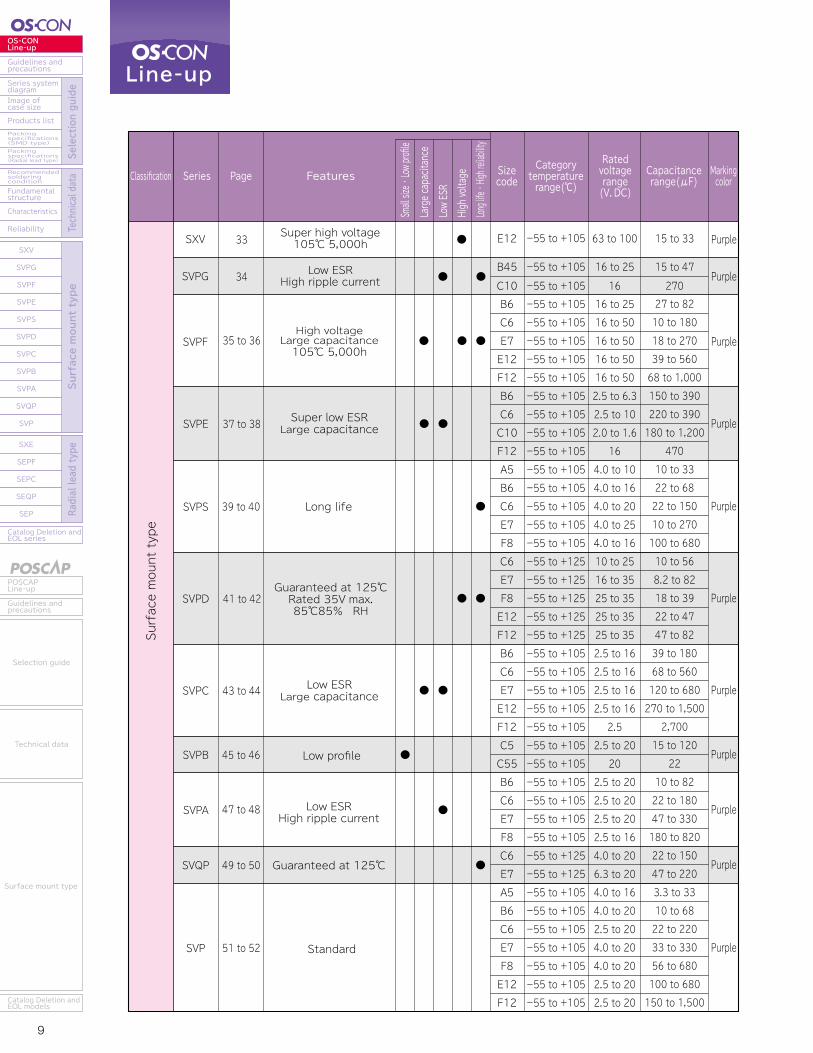
Super low ESRLarge capacitance
Super high voltage105℃ 5,000h
Low ESRHigh ripple current
Long life
Guaranteed at 125℃Rated 35V max.85℃85% RH
Low ESRHigh ripple current
Low ESRLarge capacitance
Low profile
Guaranteed at 125℃
Standard
High voltageLarge capacitance105℃ 5,000h
SEPF
SEPC
SEQP
SEP
54
SXE 53
55 to 56
57 to 58
59 to 60
Super low ESRLarge capacitance
Small sizeLow profile105℃ 5,000h
105℃ 5,000hGuaranteed at 125℃Rated 32V max.
Standard
Small size・Low profileHigh voltage
Large capacitance105℃ 5,000h
Super high voltage105℃ 5,000h
FeaturesSeriesCategorytemperaturerange(℃)
Ratedvoltagerange(V.DC)
Capacitancerange(μF)
MarkingcolorPageClassification
Large capacitance
Small size ・ Low profile
Low ESR
High voltage
Long life ・
High reliability
Sizecode FeaturesSeries
Categorytemperaturerange(℃)
Ratedvoltagerange(V.DC)
Capacitancerange(μF)
MarkingcolorPageClassification
Large capacitance
Small size ・ Low profile
Low ESR
High voltage
Long life ・
High re
liability
Sizecode
● ●
●
●● Purple
Purple
SVPF
33SXV
34SVPG
Purple
Purple
Purple
●●●
Line-up
●
● ●
●

9 10
OS-CONLine-up
Guidelines andprecautions
Series systemdiagram
Recommendedsolderingcondition
Fundamentalstructure
Characteristics
Reliability
Catalog Deletion andEOL series
SXV
SVPG
SVPF
SVPE
SVPS
SVPD
SVPC
SVPB
SVPA
SVQP
SVP
SXE
SEPF
SEPC
SEQP
SEP
Image ofcase size
Products listPackingspecifications(SMD type)Packingspecifications(Radial lead type) Se
lection guide
Technical data
Surface mount type
Radial lead type
POSCAPLine-up
Guidelines andprecautions
Catalog Deletion andEOL models
Selection guide
Technical data
Surface mount type
Catalog Deletion andEOL series
SEP
SEQP
SEPC
SEPF
SXE
SXV
SVPG
SVPF
SVPE
SVPS
SVPD
SVPC
SVPB
SVPA
SVQP
SVP
Reliability
Characteristics
Fundamentalstructure
Recommendedsolderingcondition
Packingspecifications(Radial lead type)
Packingspecifications(SMD type)
Products list
Image ofcase size
Series systemdiagram
Guidelines andprecautions
OS-CONLine-up
Surface mount type
Radial lead type
Selection guide
Technical data
Guidelines andprecautions
POSCAPLine-up
Catalog Deletion andEOL models
Surface mount type
Technical data
Selection guide
Surface mount type
●
●
●
●
●
●
●
●
●
●
SVPE
SVPS
SVPD
SVPC
SVPB
SVPA
SVQP
SVP
-55 to +105-55 to +105-55 to +105-55 to +105-55 to +105-55 to +105-55 to +105-55 to +105-55 to +105-55 to +105-55 to +105-55 to +105-55 to +105-55 to +105-55 to +125-55 to +125-55 to +125-55 to +125-55 to +125-55 to +105-55 to +105-55 to +105-55 to +105-55 to +105-55 to +105-55 to +105-55 to +105-55 to +105-55 to +105-55 to +105-55 to +125-55 to +125-55 to +105-55 to +105-55 to +105-55 to +105-55 to +105-55 to +105-55 to +105
B6C6E7E12F12B6C6C10F12A5B6C6E7F8C6E7F8E12F12B6C6E7E12F12C5C55B6C6E7F8C6E7A5B6C6E7F8E12F12
16 to 2516 to 5016 to 5016 to 5016 to 502.5 to 6.32.5 to 102.0 to 1.616
4.0 to 104.0 to 164.0 to 204.0 to 254.0 to 1610 to 2516 to 3525 to 3525 to 3525 to 352.5 to 162.5 to 162.5 to 162.5 to 162.5
2.5 to 2020
2.5 to 202.5 to 202.5 to 202.5 to 164.0 to 206.3 to 204.0 to 164.0 to 202.5 to 204.0 to 204.0 to 202.5 to 202.5 to 20
27 to 8210 to 18018 to 27039 to 56068 to 1,000150 to 390220 to 390180 to 1,200
47010 to 3322 to 6822 to 15010 to 270100 to 68010 to 568.2 to 8218 to 3922 to 4747 to 8239 to 18068 to 560120 to 680270 to 1,500
2,70015 to 120
2210 to 8222 to 18047 to 330180 to 82022 to 15047 to 2203.3 to 3310 to 6822 to 22033 to 33056 to 680100 to 680150 to 1,500
-55 to +105E12 63 to 100 15 to 33
-55 to +105B45 16 to 25 15 to 47-55 to +105C10 16 270
Purple
Purple
Purple
Purple
Purple
Purple
Purple
Purple
35 to 36
37 to 38
39 to 40
41 to 42
43 to 44
45 to 46
47 to 48
49 to 50
51 to 52
Radial lead type
●● ●
●●
-55 to +105-55 to +105-55 to +105-55 to +105-55 to +105-55 to +105-55 to +105-55 to +105-55 to +105-55 to +105-55 to +105-55 to +105-55 to +105-55 to +105-55 to +105-55 to +125-55 to +125-55 to +125-55 to +125-55 to +125-55 to +105-55 to +105-55 to +105-55 to +105-55 to +105
C55C6E7E12F13B9C55C6C7C9E7E9E12E13F13C6E7F8E12F13C6E7F8E12F13
16 to 3216 to 3516 to 3516 to 3516 to 352.56.3
2.5 to 166.3
2.5 to 162.5 to 162.5 to 1616
2.5 to 6.32.5 to 164.0 to 204.0 to 324.0 to 324.0 to 324.0 to 204.0 to 204.0 to 204.0 to 202.5 to 202.5 to 20
22 to 15022 to 18039 to 27082 to 560120 to 1,000100 to 560
220100 to 560
470100 to 820150 to 1,000180 to 1,000180 to 270470 to 820470 to 2,70022 to 1506.8 to 33015 to 68018 to 560150 to 1,20022 to 15033 to 33056 to 680100 to 680150 to 1,500
-55 to +105E12 63 to 100 15 to 33
Purple
Purple
Purple
Super low ESRLarge capacitance
Super high voltage105℃ 5,000h
Low ESRHigh ripple current
Long life
Guaranteed at 125℃Rated 35V max.85℃85% RH
Low ESRHigh ripple current
Low ESRLarge capacitance
Low profile
Guaranteed at 125℃
Standard
High voltageLarge capacitance105℃ 5,000h
SEPF
SEPC
SEQP
SEP
54
SXE 53
55 to 56
57 to 58
59 to 60
Super low ESRLarge capacitance
Small sizeLow profile105℃ 5,000h
105℃ 5,000hGuaranteed at 125℃Rated 32V max.
Standard
Small size・Low profileHigh voltage
Large capacitance105℃ 5,000h
Super high voltage105℃ 5,000h
FeaturesSeriesCategorytemperaturerange(℃)
Ratedvoltagerange(V.DC)
Capacitancerange(μF)
MarkingcolorPageClassification
Large capacitance
Small size ・ Low profile
Low ESR
High voltage
Long life ・
High reliability
Sizecode FeaturesSeries
Categorytemperaturerange(℃)
Ratedvoltagerange(V.DC)
Capacitancerange(μF)
MarkingcolorPageClassification
Large capacitance
Small size ・ Low profile
Low ESR
High voltage
Long life ・
High re
liability
Sizecode
● ●
●
●● Purple
Purple
SVPF
33SXV
34SVPG
Purple
Purple
Purple
●●●
Line-up
●
● ●
●
11 12
OS-CONLine-up
Guidelines andprecautions
Series systemdiagram
Recommendedsolderingcondition
Fundamentalstructure
Characteristics
Reliability
Catalog Deletion andEOL series
SXV
SVPG
SVPF
SVPE
SVPS
SVPD
SVPC
SVPB
SVPA
SVQP
SVP
SXE
SEPF
SEPC
SEQP
SEP
Image ofcase size
Products listPackingspecifications(SMD type)Packingspecifications(Radial lead type) Se
lection guide
Technical data
Surface mount type
Radial lead type
POSCAPLine-up
Guidelines andprecautions
Catalog Deletion andEOL models
Selection guide
Technical data
Surface mount type
Catalog Deletion andEOL series
SEP
SEQP
SEPC
SEPF
SXE
SXV
SVPG
SVPF
SVPE
SVPS
SVPD
SVPC
SVPB
SVPA
SVQP
SVP
Reliability
Characteristics
Fundamentalstructure
Recommendedsolderingcondition
Packingspecifications(Radial lead type)
Packingspecifications(SMD type)
Products list
Image ofcase size
Series systemdiagram
Guidelines andprecautions
OS-CONLine-up
Surface mount type
Radial lead type
Selection guide
Technical data
Guidelines andprecautions
POSCAPLine-up
Catalog Deletion andEOL models
Surface mount type
Technical data
Selection guide
Guidelines andprecautions
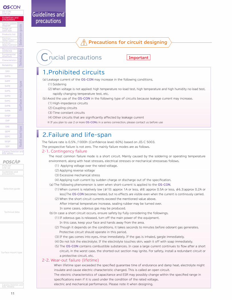
ImportantCrucial precautions1.Prohibited circuits(a)Leakage current of the OS-CON may increase in the following conditions.(1)Soldering(2)When voltage is not applied: high temperature no-load test, high temperature and high humidity no-load test,
rapidly changing temperature test, etc.(b)Avoid the use of the OS-CON in the following type of circuits because leakage current may increase.
(1)High-impedance circuits(2)Coupling circuits(3)Time constant circuits(4)Other circuits that are significantly affected by leakage current※ If you plan to use 2 or more OS-CONs in a series connection, please contact us before use
Other precautions
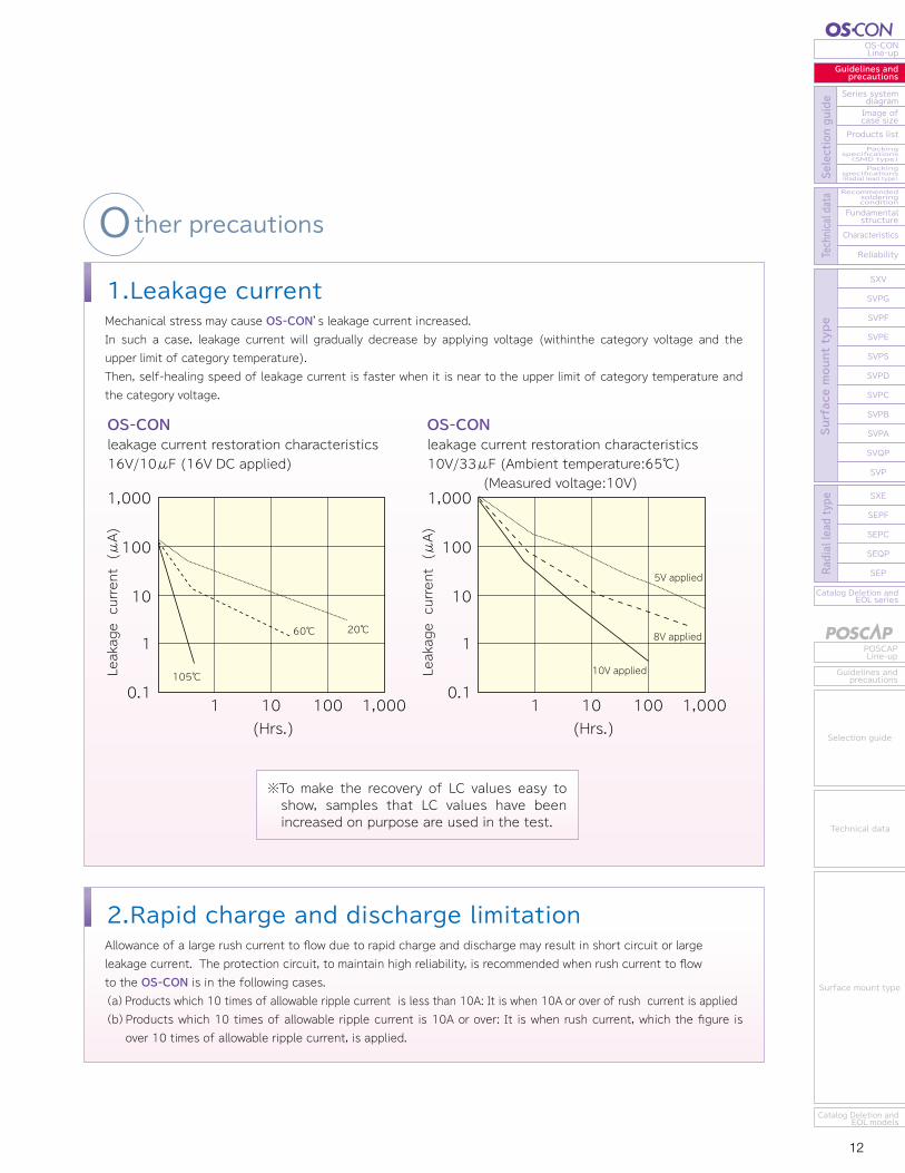
1.Leakage currentMechanical stress may cause OS-CON’s leakage current increased.In such a case, leakage current will gradually decrease by applying voltage (withinthe category voltage and the upper limit of category temperature).Then, self-healing speed of leakage current is faster when it is near to the upper limit of category temperature and the category voltage.
2.Rapid charge and discharge limitationAllowance of a large rush current to flow due to rapid charge and discharge may result in short circuit or large leakage current. The protection circuit, to maintain high reliability, is recommended when rush current to flow to the OS-CON is in the following cases.(a)Products which 10 times of allowable ripple current is less than 10A: It is when 10A or over of rush current is applied(b)Products which 10 times of allowable ripple current is 10A or over: It is when rush current, which the figure is
over 10 times of allowable ripple current, is applied.
2.Failure and life-spanThe failure rate is 0.5% /1000h (Confidence level: 60%) based on JIS C 5003.The prospective failure is not zero. The mainly failure modes are as follows.2-1. Contingency failure
The most common failure mode is a short circuit. Mainly caused by the soldering or operating temperature environment, along with heat stresses, electrical stresses or mechanical stressesas follows. (1) Applying voltage over the rated voltage.(2)Applying reverse voltage(3)Excessive mechanical stress(4)Applying rush current by sudden charge or discharge out of the specification.
(a)The following phenomenon is seen when short-current is applied to the OS-CON.(1)When current is relatively low (φ10: approx 1A or less, φ8: approx 0.5A or less, φ6.3:approx 0.2A or
less)The OS-CON becomes heated, but no effects are visible even when the current is continously carried.(2)When the short circuit currents exceed the mentioned value above. After internal temperature increase, sealing rubber may be turned over. In some cases, odorous gas may be produced.
(b)In case a short circuit occurs, ensure safety by fully considering the followings.(1)If odorous gas is released, turn off the main power of the equipment.
In this case, keep your face and hands away from the area. (2)Though it depends on the conditions, it takes seconds to minutes before odorant gas generates. Protective circuit should operate in this period.(3)If the gas comes into eyes, rinse immediately. If the gas is inhaled, gargle immediately.(4)Do not lick the electrolyte. If the electrolyte touches skin, wash it off with soap immediately.(5)The OS-CON contains combustible substances. In case a large current continues to flow after a short
circuit, in the worst case, the shorted-out section may ignite. For safety, install a redundant circuit or a protective circuit, etc.
2-2. Wear-out failure (lifetime) When lifetime span exceeded the specified guarantee time of endurance and damp heat, electrolyte might insulate and cause electric characteristic changed. This is called an open circuit.The electric characteristics of capacitance and ESR may possibly change within the specified range in specifications even if it is used under the condition of the rated voltage,electric and mechanical performance. Please note it when designing.
OS-CONleakage current restoration characteristics16V/10μF (16V DC applied)
OS-CONleakage current restoration characteristics10V/33μF (Ambient temperature:65℃) (Measured voltage:10V)
105℃Leakage current (μA)
Leakage current (μA)
(Hrs.)
1,000
100
10
1
0.11 10 100 1,000
60℃ 20℃
(Hrs.)
1,000
100
10
1
0.11 10 100 1,000
5V applied
8V applied
10V applied
※To make the recovery of LC values easy to show, samples that LC values have been increased on purpose are used in the test.
Precautions for circuit designing
11 12
OS-CONLine-up
Guidelines andprecautions
Series systemdiagram
Recommendedsolderingcondition
Fundamentalstructure
Characteristics
Reliability
Catalog Deletion andEOL series
SXV
SVPG
SVPF
SVPE
SVPS
SVPD
SVPC
SVPB
SVPA
SVQP
SVP
SXE
SEPF
SEPC
SEQP
SEP
Image ofcase size
Products listPackingspecifications(SMD type)Packingspecifications(Radial lead type) Se
lection guide
Technical data
Surface mount type
Radial lead type
POSCAPLine-up
Guidelines andprecautions
Catalog Deletion andEOL models
Selection guide
Technical data
Surface mount type
Catalog Deletion andEOL series
SEP
SEQP
SEPC
SEPF
SXE
SXV
SVPG
SVPF
SVPE
SVPS
SVPD
SVPC
SVPB
SVPA
SVQP
SVP
Reliability
Characteristics
Fundamentalstructure
Recommendedsolderingcondition
Packingspecifications(Radial lead type)
Packingspecifications(SMD type)
Products list
Image ofcase size
Series systemdiagram
Guidelines andprecautions
OS-CONLine-up
Surface mount type
Radial lead type
Selection guide
Technical data
Guidelines andprecautions
POSCAPLine-up
Catalog Deletion andEOL models
Surface mount type
Technical data
Selection guide
Guidelines andprecautions
ImportantCrucial precautions1.Prohibited circuits(a)Leakage current of the OS-CON may increase in the following conditions.(1)Soldering(2)When voltage is not applied: high temperature no-load test, high temperature and high humidity no-load test,
rapidly changing temperature test, etc.(b)Avoid the use of the OS-CON in the following type of circuits because leakage current may increase.
(1)High-impedance circuits(2)Coupling circuits(3)Time constant circuits(4)Other circuits that are significantly affected by leakage current※ If you plan to use 2 or more OS-CONs in a series connection, please contact us before use
Other precautions
1.Leakage currentMechanical stress may cause OS-CON’s leakage current increased.In such a case, leakage current will gradually decrease by applying voltage (withinthe category voltage and the upper limit of category temperature).Then, self-healing speed of leakage current is faster when it is near to the upper limit of category temperature and the category voltage.
2.Rapid charge and discharge limitationAllowance of a large rush current to flow due to rapid charge and discharge may result in short circuit or large leakage current. The protection circuit, to maintain high reliability, is recommended when rush current to flow to the OS-CON is in the following cases.(a)Products which 10 times of allowable ripple current is less than 10A: It is when 10A or over of rush current is applied(b)Products which 10 times of allowable ripple current is 10A or over: It is when rush current, which the figure is
over 10 times of allowable ripple current, is applied.
2.Failure and life-spanThe failure rate is 0.5% /1000h (Confidence level: 60%) based on JIS C 5003.The prospective failure is not zero. The mainly failure modes are as follows.2-1. Contingency failure
The most common failure mode is a short circuit. Mainly caused by the soldering or operating temperature environment, along with heat stresses, electrical stresses or mechanical stressesas follows. (1) Applying voltage over the rated voltage.(2)Applying reverse voltage(3)Excessive mechanical stress(4)Applying rush current by sudden charge or discharge out of the specification.
(a)The following phenomenon is seen when short-current is applied to the OS-CON.(1)When current is relatively low (φ10: approx 1A or less, φ8: approx 0.5A or less, φ6.3:approx 0.2A or
less)The OS-CON becomes heated, but no effects are visible even when the current is continously carried.(2)When the short circuit currents exceed the mentioned value above. After internal temperature increase, sealing rubber may be turned over. In some cases, odorous gas may be produced.
(b)In case a short circuit occurs, ensure safety by fully considering the followings.(1)If odorous gas is released, turn off the main power of the equipment.
In this case, keep your face and hands away from the area. (2)Though it depends on the conditions, it takes seconds to minutes before odorant gas generates. Protective circuit should operate in this period.(3)If the gas comes into eyes, rinse immediately. If the gas is inhaled, gargle immediately.(4)Do not lick the electrolyte. If the electrolyte touches skin, wash it off with soap immediately.(5)The OS-CON contains combustible substances. In case a large current continues to flow after a short
circuit, in the worst case, the shorted-out section may ignite. For safety, install a redundant circuit or a protective circuit, etc.
2-2. Wear-out failure (lifetime) When lifetime span exceeded the specified guarantee time of endurance and damp heat, electrolyte might insulate and cause electric characteristic changed. This is called an open circuit.The electric characteristics of capacitance and ESR may possibly change within the specified range in specifications even if it is used under the condition of the rated voltage,electric and mechanical performance. Please note it when designing.
OS-CONleakage current restoration characteristics16V/10μF (16V DC applied)
OS-CONleakage current restoration characteristics10V/33μF (Ambient temperature:65℃) (Measured voltage:10V)
105℃Leakage current (μA)
Leakage current (μA)
(Hrs.)
1,000
100
10
1
0.11 10 100 1,000
60℃ 20℃
(Hrs.)
1,000
100
10
1
0.11 10 100 1,000
5V applied
8V applied
10V applied
※To make the recovery of LC values easy to show, samples that LC values have been increased on purpose are used in the test.
Precautions for circuit designing
13 14
OS-CONLine-up
Guidelines andprecautions
Series systemdiagram
Recommendedsolderingcondition
Fundamentalstructure
Characteristics
Reliability
Catalog Deletion andEOL series
SXV
SVPG
SVPF
SVPE
SVPS
SVPD
SVPC
SVPB
SVPA
SVQP
SVP
SXE
SEPF
SEPC
SEQP
SEP
Image ofcase size
Products listPackingspecifications(SMD type)Packingspecifications(Radial lead type) Se
lection guide
Technical data
Surface mount type
Radial lead type
POSCAPLine-up
Guidelines andprecautions
Catalog Deletion andEOL models
Selection guide
Technical data
Surface mount type
Catalog Deletion andEOL series
SEP
SEQP
SEPC
SEPF
SXE
SXV
SVPG
SVPF
SVPE
SVPS
SVPD
SVPC
SVPB
SVPA
SVQP
SVP
Reliability
Characteristics
Fundamentalstructure
Recommendedsolderingcondition
Packingspecifications(Radial lead type)
Packingspecifications(SMD type)
Products list
Image ofcase size
Series systemdiagram
Guidelines andprecautions
OS-CONLine-up
Surface mount type
Radial lead type
Selection guide
Technical data
Guidelines andprecautions
POSCAPLine-up
Catalog Deletion andEOL models
Surface mount type
Technical data
Selection guide
Guidelines andprecautions
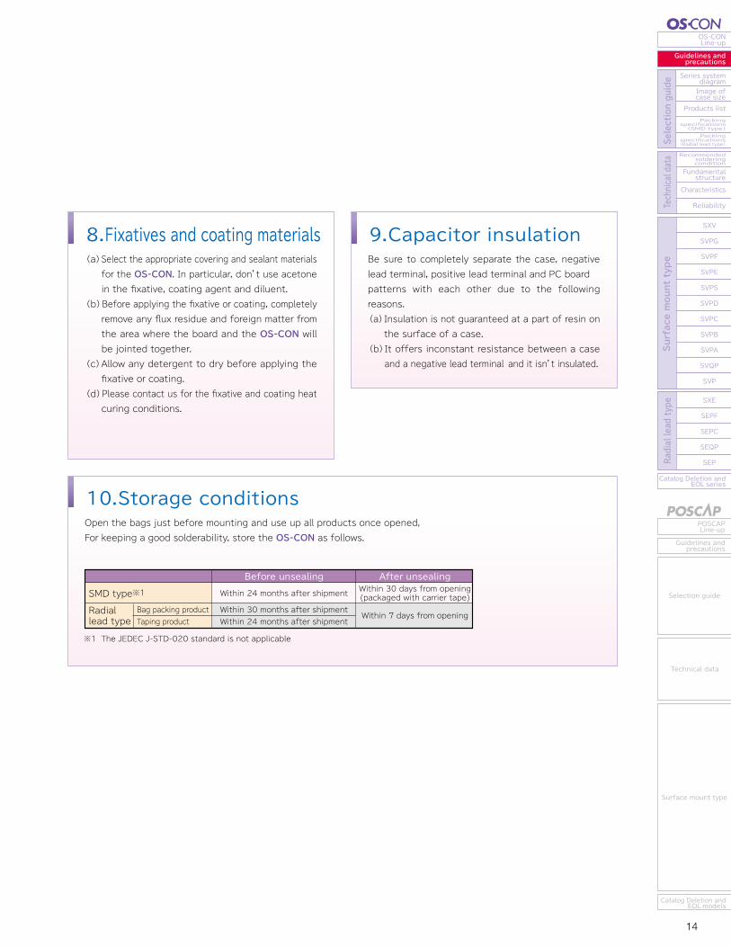
8.Fixatives and coating materials(a)Select the appropriate covering and sealant materials
for the OS-CON. In particular, don’t use acetone in the fixative, coating agent and diluent.
(b)Before applying the fixative or coating, completely remove any flux residue and foreign matter from the area where the board and the OS-CON will be jointed together.
(c)Allow any detergent to dry before applying the fixative or coating.
(d)Please contact us for the fixative and coating heat curing conditions.
10.Storage conditionsOpen the bags just before mounting and use up all products once opened, For keeping a good solderability, store the OS-CON as follows.
9.Capacitor insulationBe sure to completely separate the case, negative lead terminal, positive lead terminal and PC board patterns with each other due to the following reasons.(a)Insulation is not guaranteed at a part of resin on
the surface of a case.(b)It offers inconstant resistance between a case
and a negative lead terminal and it isn’t insulated.
※1 The JEDEC J-STD-020 standard is not applicable
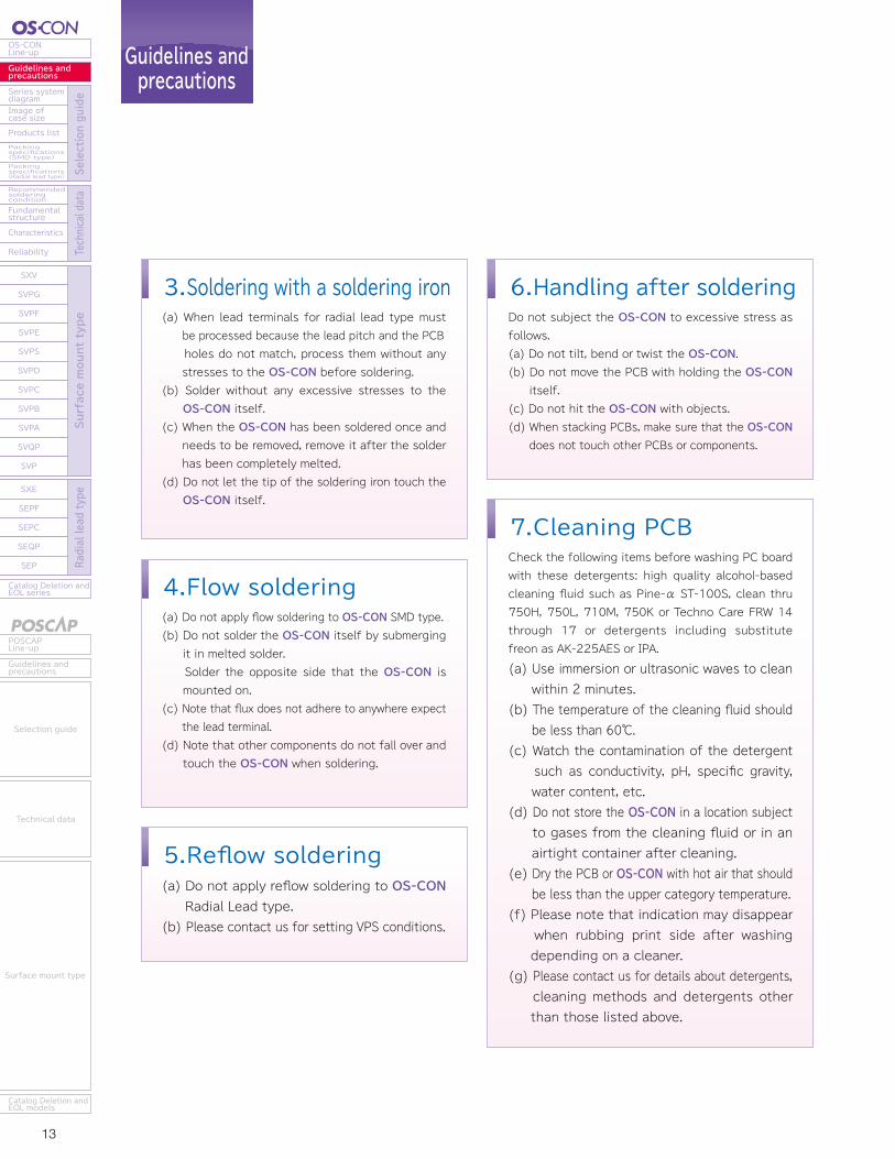
5.Reflow soldering(a) Do not apply reflow soldering to OS-CON Radial Lead type.
(b) Please contact us for setting VPS conditions.
7.Cleaning PCBCheck the following items before washing PC board with these detergents: high quality alcohol-based cleaning fluid such as Pine-α ST-100S, clean thru 750H, 750L, 710M, 750K or Techno Care FRW 14 through 17 or detergents including substitute freon as AK-225AES or IPA.
(a) Use immersion or ultrasonic waves to clean within 2 minutes.
(b) The temperature of the cleaning fluid should be less than 60℃.
(c) Watch the contamination of the detergent such as conductivity, pH, specific gravity, water content, etc.
(d) Do not store the OS-CON in a location subject to gases from the cleaning fluid or in an airtight container after cleaning.
(e) Dry the PCB or OS-CON with hot air that should be less than the upper category temperature.
(f) Please note that indication may disappear when rubbing print side after washing depending on a cleaner.
(g) Please contact us for details about detergents, cleaning methods and detergents other than those listed above.
6.Handling after solderingDo not subject the OS-CON to excessive stress as follows.(a) Do not tilt, bend or twist the OS-CON.(b) Do not move the PCB with holding the OS-CON itself.
(c) Do not hit the OS-CON with objects.(d) When stacking PCBs, make sure that the OS-CON
does not touch other PCBs or components.
3.Soldering with a soldering iron(a) When lead terminals for radial lead type must
be processed because the lead pitch and the PCB holes do not match, process them without any stresses to the OS-CON before soldering.
(b) Solder without any excessive stresses to the OS-CON itself.
(c) When the OS-CON has been soldered once and needs to be removed, remove it after the solder has been completely melted.
(d) Do not let the tip of the soldering iron touch the OS-CON itself.
4.Flow soldering(a) Do not apply flow soldering to OS-CON SMD type.(b) Do not solder the OS-CON itself by submerging it in melted solder. Solder the opposite side that the OS-CON is mounted on.
(c) Note that flux does not adhere to anywhere expect the lead terminal.
(d) Note that other components do not fall over and touch the OS-CON when soldering.
SMD type※1 Within 30 days from opening(packaged with carrier tape)
Radiallead type
Bag packing productTaping product
Within 7 days from opening
Within 24 months after shipment
Within 30 months after shipmentWithin 24 months after shipment
Before unsealing After unsealing
13 14
OS-CONLine-up
Guidelines andprecautions
Series systemdiagram
Recommendedsolderingcondition
Fundamentalstructure
Characteristics
Reliability
Catalog Deletion andEOL series
SXV
SVPG
SVPF
SVPE
SVPS
SVPD
SVPC
SVPB
SVPA
SVQP
SVP
SXE
SEPF
SEPC
SEQP
SEP
Image ofcase size
Products listPackingspecifications(SMD type)Packingspecifications(Radial lead type) Se
lection guide
Technical data
Surface mount type
Radial lead type
POSCAPLine-up
Guidelines andprecautions
Catalog Deletion andEOL models
Selection guide
Technical data
Surface mount type
Catalog Deletion andEOL series
SEP
SEQP
SEPC
SEPF
SXE
SXV
SVPG
SVPF
SVPE
SVPS
SVPD
SVPC
SVPB
SVPA
SVQP
SVP
Reliability
Characteristics
Fundamentalstructure
Recommendedsolderingcondition
Packingspecifications(Radial lead type)
Packingspecifications(SMD type)
Products list
Image ofcase size
Series systemdiagram
Guidelines andprecautions
OS-CONLine-up
Surface mount type
Radial lead type
Selection guide
Technical data
Guidelines andprecautions
POSCAPLine-up
Catalog Deletion andEOL models
Surface mount type
Technical data
Selection guide
Guidelines andprecautions
8.Fixatives and coating materials(a)Select the appropriate covering and sealant materials
for the OS-CON. In particular, don’t use acetone in the fixative, coating agent and diluent.
(b)Before applying the fixative or coating, completely remove any flux residue and foreign matter from the area where the board and the OS-CON will be jointed together.
(c)Allow any detergent to dry before applying the fixative or coating.
(d)Please contact us for the fixative and coating heat curing conditions.
10.Storage conditionsOpen the bags just before mounting and use up all products once opened, For keeping a good solderability, store the OS-CON as follows.
9.Capacitor insulationBe sure to completely separate the case, negative lead terminal, positive lead terminal and PC board patterns with each other due to the following reasons.(a)Insulation is not guaranteed at a part of resin on
the surface of a case.(b)It offers inconstant resistance between a case
and a negative lead terminal and it isn’t insulated.
※1 The JEDEC J-STD-020 standard is not applicable
5.Reflow soldering(a) Do not apply reflow soldering to OS-CON Radial Lead type.
(b) Please contact us for setting VPS conditions.
7.Cleaning PCBCheck the following items before washing PC board with these detergents: high quality alcohol-based cleaning fluid such as Pine-α ST-100S, clean thru 750H, 750L, 710M, 750K or Techno Care FRW 14 through 17 or detergents including substitute freon as AK-225AES or IPA.
(a) Use immersion or ultrasonic waves to clean within 2 minutes.
(b) The temperature of the cleaning fluid should be less than 60℃.
(c) Watch the contamination of the detergent such as conductivity, pH, specific gravity, water content, etc.
(d) Do not store the OS-CON in a location subject to gases from the cleaning fluid or in an airtight container after cleaning.
(e) Dry the PCB or OS-CON with hot air that should be less than the upper category temperature.
(f) Please note that indication may disappear when rubbing print side after washing depending on a cleaner.
(g) Please contact us for details about detergents, cleaning methods and detergents other than those listed above.
6.Handling after solderingDo not subject the OS-CON to excessive stress as follows.(a) Do not tilt, bend or twist the OS-CON.(b) Do not move the PCB with holding the OS-CON itself.
(c) Do not hit the OS-CON with objects.(d) When stacking PCBs, make sure that the OS-CON
does not touch other PCBs or components.
3.Soldering with a soldering iron(a) When lead terminals for radial lead type must
be processed because the lead pitch and the PCB holes do not match, process them without any stresses to the OS-CON before soldering.
(b) Solder without any excessive stresses to the OS-CON itself.
(c) When the OS-CON has been soldered once and needs to be removed, remove it after the solder has been completely melted.
(d) Do not let the tip of the soldering iron touch the OS-CON itself.
4.Flow soldering(a) Do not apply flow soldering to OS-CON SMD type.(b) Do not solder the OS-CON itself by submerging it in melted solder. Solder the opposite side that the OS-CON is mounted on.
(c) Note that flux does not adhere to anywhere expect the lead terminal.
(d) Note that other components do not fall over and touch the OS-CON when soldering.
SMD type※1 Within 30 days from opening(packaged with carrier tape)
Radiallead type
Bag packing productTaping product
Within 7 days from opening
Within 24 months after shipment
Within 30 months after shipmentWithin 24 months after shipment
Before unsealing After unsealing
15 16
OS-CONLine-up
Guidelines andprecautions
Series systemdiagram
Recommendedsolderingcondition
Fundamentalstructure
Characteristics
Reliability
Catalog Deletion andEOL series
SXV
SVPG
SVPF
SVPE
SVPS
SVPD
SVPC
SVPB
SVPA
SVQP
SVP
SXE
SEPF
SEPC
SEQP
SEP
Image ofcase size
Products listPackingspecifications(SMD type)Packingspecifications(Radial lead type) Se
lection guide
Technical data
Surface mount type
Radial lead type
POSCAPLine-up
Guidelines andprecautions
Catalog Deletion andEOL models
Selection guide
Technical data
Surface mount type
Catalog Deletion andEOL series
SEP
SEQP
SEPC
SEPF
SXE
SXV
SVPG
SVPF
SVPE
SVPS
SVPD
SVPC
SVPB
SVPA
SVQP
SVP
Reliability
Characteristics
Fundamentalstructure
Recommendedsolderingcondition
Packingspecifications(Radial lead type)
Packingspecifications(SMD type)
Products list
Image ofcase size
Series systemdiagram
Guidelines andprecautions
OS-CONLine-up
Surface mount type
Radial lead type
Selection guide
Technical data
Guidelines andprecautions
POSCAPLine-up
Catalog Deletion andEOL models
Surface mount type
Technical data
Selection guide
Series systemdiagram
Image ofcase size
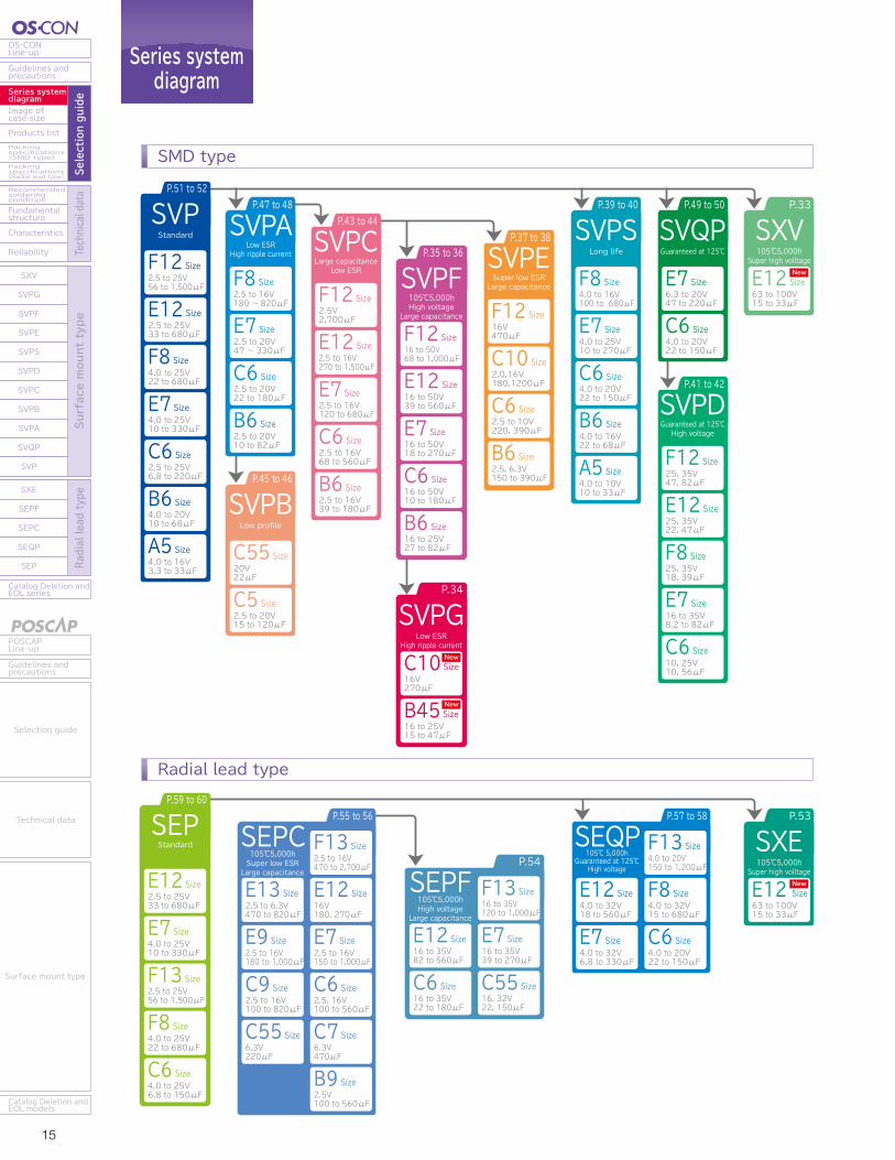
P.51 to 52
SVP
2.5 to 25V56 to 1,500μF
F12 Size
2.5 to 25V33 to 680μF
E12 Size
4.0 to 25V22 to 680μF
F8 Size
4.0 to 25V10 to 330μF
E7 Size
2.5 to 25V6.8 to 220μF
C6 Size
4.0 to 20V10 to 68μF
B6 Size
4.0 to 16V3.3 to 33μF
A5 Size
P.43 to 44
SVPC
2.5V2,700μF
F12 Size
2.5 to 16V270 to 1,500μF
E12 Size
2.5 to 16V120 to 680μF
E7 Size
2.5 to 16V68 to 560μF
C6 Size
2.5 to 16V39 to 180μF
B6 Size
P.41 to 42
SVPD
25, 35V47, 82μF
F12 Size
25, 35V22, 47μF
E12 Size
25, 35V18, 39μF
F8 Size
16 to 35V8.2 to 82μF
E7 Size
10, 25V10, 56μF
C6 Size
P.39 to 40
SVPS
4.0 to 16V100 to 680μF
F8 Size
4.0 to 25V10 to 270μF
E7 Size
4.0 to 20V22 to 150μF
C6 Size
4.0 to 16V22 to 68μF
B6 Size
4.0 to 10V10 to 33μF
A5 Size
P.49 to 50
SVQP
6.3 to 20V47 to 220μF
E7 Size
4.0 to 20V22 to 150μF
C6 Size
P.45 to 46
SVPB
20V22μF
C55 Size
2.5 to 20V15 to 120μF
C5 Size
P.47 to 48
2.5 to 16V180 ~ 820μF
F8 Size
2.5 to 20V47 ~ 330μF
E7 Size
2.5 to 20V22 to 180μF
C6 Size
2.5 to 20V10 to 82μF
B6 Size
P.55 to 56
2.5 to 16V470 to 2,700μF
F13 Size
2.5 to 6.3V470 to 820μF
E13 Size16V180, 270μF
E12 Size
2.5 to 16V180 to 1,000μF
E9 Size2.5 to 16V150 to 1,000μF
E7 Size
2.5 to 16V100 to 820μF
C9 Size2.5, 16V100 to 560μF
C6 Size
6.3V220μF
C55 Size6.3V470μF
C7 Size
2.5V100 to 560μF
B9 Size
SEPCP.57 to 58
4.0 to 20V150 to 1,200μF
F13 Size
4.0 to 32V18 to 560μF
E12 Size4.0 to 32V15 to 680μF
F8 Size
4.0 to 32V6.8 to 330μF
E7 Size4.0 to 20V22 to 150μF
C6 Size
SVPA P.37 to 38
16V470μF
F12 Size
2.0,16V180,1200μF
C10 Size
2.5 to 10V220, 390μF
C6 Size
2.5, 6.3V150 to 390μF
B6 Size
SVPE
SEQP
Low profile
P.34
SVPG
16V270μF
C10 Size
16 to 25V15 to 47μF
B45 Size
Low ESRHigh ripple current
Low ESRHigh ripple current
Large capacitanceLow ESR
Guaranteed at 125℃
P.53
SXE
63 to 100V15 to 33μF
E12 Size105℃5,000h
Super high volltage
P.33
SXV
63 to 100V15 to 33μF
E12 Size105℃5,000h
Super high volltage
Standard
Guaranteed at 125℃High voltage
Long life
Super low ESRLarge capacitance
105℃ 5,000hGuaranteed at 125℃
High voltage
P.59 to 60
2.5 to 25V33 to 680μF
E12 Size
4.0 to 25V10 to 330μF
E7 Size
2.5 to 25V56 to 1,500μF
F13 Size
4.0 to 25V22 to 680μF
F8 Size
SEPStandard
4.0 to 25V6.8 to 150μF
C6 Size
105℃5,000hSuper low ESRLarge capacitance
P.54
16, 32V22, 150μF
C55 Size
SEPF105℃5,000hHigh voltage
Large capacitance
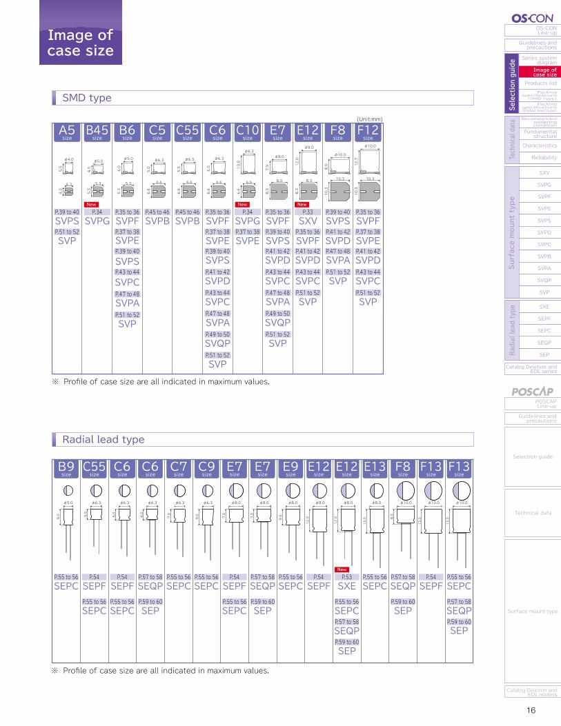
SVPS
φ10.0
12.7
10.3
10.3
φ4.0
5.5
4.3
4.3
B6size
B45size
A5size
C5size
SVPBP.45 to 46
C55size
SVPBP.45 to 46
C6size
P.35 to 36
SVPEP.37 to 38
SVPSP.39 to 40
SVPDP.41 to 42
SVPCP.43 to 44
SVPAP.47 to 48
SVQPP.49 to 50
SVPP.51 to 52
E7size
SVPFP.35 to 36
E12size
SVPFP.35 to 36SXVP.33
F12size
SVPFP.35 to 36
SVPDP.41 to 42
SVPCP.43 to 44
SVPAP.47 to 48
SVQPP.49 to 50
SVPP.51 to 52
SVPSP.39 to 40
SVPCP.43 to 44
SVPP.51 to 52
SVPDP.41 to 42
SVPEP.37 to 38
SVPDP.41 to 42
SVPCP.43 to 44
SVPP.51 to 52
φ5.0
6.0
5.3
5.3
5.3
5.3
φ6.3
6.0
6.6
6.6
φ6.3
5.5
6.6
6.6
φ6.3
5.0
6.6
6.6
φ8.0
7.0
8.3
8.3
φ8.0
12.0
8.3
8.3
P.39 to 40
SVPP.51 to 52
C6size
C6size
SEQPP.57 to 58
SEPP.59 to 60
SEPCP.55 to 56
E7size
F8size
B9size
SEPCP.55 to 56
C9size
SEPCP.55 to 56
SEQPP.57 to 58
SEPP.59 to 60
SEQPP.57 to 58
SEPP.59 to 60
E9size
SEPCP.55 to 56
E12size
SEPCP.55 to 56
SXEP.53
SEQPP.57 to 58
SEPP.59 to 60
E13size
SEPCP.55 to 56
F13size
SEPCP.55 to 56
SEQPP.57 to 58
6.0
φ6.3
7.0
φ8.0
E7size
SEPFP.54
SEPCP.55 to 56
7.0
φ8.0
8.0
φ10.0
9.0
φ8.0 φ8.0
12.0
E12size
SEPFP.54
φ8.0
12.0
13.0
φ8.0
13.0
φ10.0
9.0
φ6.3
C7size
SEPCP.55 to 56
7.0
φ6.3
9.0
φ5.0
6.0
φ6.3
C55size
SEPFP.54
SEPCP.55 to 56
5.5
φ6.3
(Unit:mm)
SVPFSVPF
SEPFP.54
P.35 to 36
SVPEP.37 to 38
SVPSP.39 to 40
SVPCP.43 to 44
SVPAP.47 to 48
SVPP.51 to 52
C10size
P.34
φ6.3
10.0
6.6
6.6
SVPGP.37 to 38SVPE
P.35 to 36
16 to 50V68 to 1,000μF
F12 Size
16 to 50V39 to 560μF
E12 Size
16 to 50V18 to 270μF
E7 Size
16 to 50V10 to 180μF
C6 Size
SVPF105℃5,000hHigh voltage
Large capacitance
F13size
SEPFP.54
13.0
φ10.0
※ Profile of case size are all indicated in maximum values.
※ Profile of case size are all indicated in maximum values.
16 to 25V27 to 82μF
B6 Size
F8size
SVPSP.39 to 40
SVPDP.41 to 42
SVPAP.47 to 48
SVPP.51 to 52
φ10.0
8.0
10.3
10.3
16 to 35V82 to 560μF
E12 Size
16 to 35V22 to 180μF
C6 Size
16 to 35V120 to 1,000μF
F13 Size
16 to 35V39 to 270μF
E7 Size
SMD type SMD type
Radial lead type
Radial lead type
SVPGP.34
NewNew New
New
New
New
New
New
SEPP.59 to 60
φ5.0
4.5
15 16
OS-CONLine-up
Guidelines andprecautions
Series systemdiagram
Recommendedsolderingcondition
Fundamentalstructure
Characteristics
Reliability
Catalog Deletion andEOL series
SXV
SVPG
SVPF
SVPE
SVPS
SVPD
SVPC
SVPB
SVPA
SVQP
SVP
SXE
SEPF
SEPC
SEQP
SEP
Image ofcase size
Products listPackingspecifications(SMD type)Packingspecifications(Radial lead type) Se
lection guide
Technical data
Surface mount type
Radial lead type
POSCAPLine-up
Guidelines andprecautions
Catalog Deletion andEOL models
Selection guide
Technical data
Surface mount type
Catalog Deletion andEOL series
SEP
SEQP
SEPC
SEPF
SXE
SXV
SVPG
SVPF
SVPE
SVPS
SVPD
SVPC
SVPB
SVPA
SVQP
SVP
Reliability
Characteristics
Fundamentalstructure
Recommendedsolderingcondition
Packingspecifications(Radial lead type)
Packingspecifications(SMD type)
Products list
Image ofcase size
Series systemdiagram
Guidelines andprecautions
OS-CONLine-up
Surface mount type
Radial lead type
Selection guide
Technical data
Guidelines andprecautions
POSCAPLine-up
Catalog Deletion andEOL models
Surface mount type
Technical data
Selection guide
Series systemdiagram
Image ofcase size
P.51 to 52
SVP
2.5 to 25V56 to 1,500μF
F12 Size
2.5 to 25V33 to 680μF
E12 Size
4.0 to 25V22 to 680μF
F8 Size
4.0 to 25V10 to 330μF
E7 Size
2.5 to 25V6.8 to 220μF
C6 Size
4.0 to 20V10 to 68μF
B6 Size
4.0 to 16V3.3 to 33μF
A5 Size
P.43 to 44
SVPC
2.5V2,700μF
F12 Size
2.5 to 16V270 to 1,500μF
E12 Size
2.5 to 16V120 to 680μF
E7 Size
2.5 to 16V68 to 560μF
C6 Size
2.5 to 16V39 to 180μF
B6 Size
P.41 to 42
SVPD
25, 35V47, 82μF
F12 Size
25, 35V22, 47μF
E12 Size
25, 35V18, 39μF
F8 Size
16 to 35V8.2 to 82μF
E7 Size
10, 25V10, 56μF
C6 Size
P.39 to 40
SVPS
4.0 to 16V100 to 680μF
F8 Size
4.0 to 25V10 to 270μF
E7 Size
4.0 to 20V22 to 150μF
C6 Size
4.0 to 16V22 to 68μF
B6 Size
4.0 to 10V10 to 33μF
A5 Size
P.49 to 50
SVQP
6.3 to 20V47 to 220μF
E7 Size
4.0 to 20V22 to 150μF
C6 Size
P.45 to 46
SVPB
20V22μF
C55 Size
2.5 to 20V15 to 120μF
C5 Size
P.47 to 48
2.5 to 16V180 ~ 820μF
F8 Size
2.5 to 20V47 ~ 330μF
E7 Size
2.5 to 20V22 to 180μF
C6 Size
2.5 to 20V10 to 82μF
B6 Size
P.55 to 56
2.5 to 16V470 to 2,700μF
F13 Size
2.5 to 6.3V470 to 820μF
E13 Size16V180, 270μF
E12 Size
2.5 to 16V180 to 1,000μF
E9 Size2.5 to 16V150 to 1,000μF
E7 Size
2.5 to 16V100 to 820μF
C9 Size2.5, 16V100 to 560μF
C6 Size
6.3V220μF
C55 Size6.3V470μF
C7 Size
2.5V100 to 560μF
B9 Size
SEPCP.57 to 58
4.0 to 20V150 to 1,200μF
F13 Size
4.0 to 32V18 to 560μF
E12 Size4.0 to 32V15 to 680μF
F8 Size
4.0 to 32V6.8 to 330μF
E7 Size4.0 to 20V22 to 150μF
C6 Size
SVPA P.37 to 38
16V470μF
F12 Size
2.0,16V180,1200μF
C10 Size
2.5 to 10V220, 390μF
C6 Size
2.5, 6.3V150 to 390μF
B6 Size
SVPE
SEQP
Low profile
P.34
SVPG
16V270μF
C10 Size
16 to 25V15 to 47μF
B45 Size
Low ESRHigh ripple current
Low ESRHigh ripple current
Large capacitanceLow ESR
Guaranteed at 125℃
P.53
SXE
63 to 100V15 to 33μF
E12 Size105℃5,000h
Super high volltage
P.33
SXV
63 to 100V15 to 33μF
E12 Size105℃5,000h
Super high volltage
Standard
Guaranteed at 125℃High voltage
Long life
Super low ESRLarge capacitance
105℃ 5,000hGuaranteed at 125℃
High voltage
P.59 to 60
2.5 to 25V33 to 680μF
E12 Size
4.0 to 25V10 to 330μF
E7 Size
2.5 to 25V56 to 1,500μF
F13 Size
4.0 to 25V22 to 680μF
F8 Size
SEPStandard
4.0 to 25V6.8 to 150μF
C6 Size
105℃5,000hSuper low ESRLarge capacitance
P.54
16, 32V22, 150μF
C55 Size
SEPF105℃5,000hHigh voltage
Large capacitance
SVPS
φ10.0
12.7
10.3
10.3
φ4.0
5.5
4.3
4.3
B6size
B45size
A5size
C5size
SVPBP.45 to 46
C55size
SVPBP.45 to 46
C6size
P.35 to 36
SVPEP.37 to 38
SVPSP.39 to 40
SVPDP.41 to 42
SVPCP.43 to 44
SVPAP.47 to 48
SVQPP.49 to 50
SVPP.51 to 52
E7size
SVPFP.35 to 36
E12size
SVPFP.35 to 36SXVP.33
F12size
SVPFP.35 to 36
SVPDP.41 to 42
SVPCP.43 to 44
SVPAP.47 to 48
SVQPP.49 to 50
SVPP.51 to 52
SVPSP.39 to 40
SVPCP.43 to 44
SVPP.51 to 52
SVPDP.41 to 42
SVPEP.37 to 38
SVPDP.41 to 42
SVPCP.43 to 44
SVPP.51 to 52
φ5.0
6.0
5.3
5.3
5.3
5.3
φ6.3
6.0
6.6
6.6
φ6.3
5.5
6.6
6.6
φ6.3
5.0
6.6
6.6
φ8.0
7.0
8.3
8.3
φ8.0
12.0
8.3
8.3
P.39 to 40
SVPP.51 to 52
C6size
C6size
SEQPP.57 to 58
SEPP.59 to 60
SEPCP.55 to 56
E7size
F8size
B9size
SEPCP.55 to 56
C9size
SEPCP.55 to 56
SEQPP.57 to 58
SEPP.59 to 60
SEQPP.57 to 58
SEPP.59 to 60
E9size
SEPCP.55 to 56
E12size
SEPCP.55 to 56
SXEP.53
SEQPP.57 to 58
SEPP.59 to 60
E13size
SEPCP.55 to 56
F13size
SEPCP.55 to 56
SEQPP.57 to 58
6.0
φ6.3
7.0
φ8.0
E7size
SEPFP.54
SEPCP.55 to 56
7.0
φ8.0
8.0
φ10.0
9.0
φ8.0 φ8.0
12.0
E12size
SEPFP.54
φ8.0
12.0
13.0
φ8.0
13.0
φ10.0
9.0
φ6.3
C7size
SEPCP.55 to 56
7.0
φ6.3
9.0
φ5.0
6.0
φ6.3
C55size
SEPFP.54
SEPCP.55 to 56
5.5
φ6.3
(Unit:mm)
SVPFSVPF
SEPFP.54
P.35 to 36
SVPEP.37 to 38
SVPSP.39 to 40
SVPCP.43 to 44
SVPAP.47 to 48
SVPP.51 to 52
C10size
P.34
φ6.3
10.0
6.6
6.6
SVPGP.37 to 38SVPE
P.35 to 36
16 to 50V68 to 1,000μF
F12 Size
16 to 50V39 to 560μF
E12 Size
16 to 50V18 to 270μF
E7 Size
16 to 50V10 to 180μF
C6 Size
SVPF105℃5,000hHigh voltage
Large capacitance
F13size
SEPFP.54
13.0
φ10.0
※ Profile of case size are all indicated in maximum values.
※ Profile of case size are all indicated in maximum values.
16 to 25V27 to 82μF
B6 Size
F8size
SVPSP.39 to 40
SVPDP.41 to 42
SVPAP.47 to 48
SVPP.51 to 52
φ10.0
8.0
10.3
10.3
16 to 35V82 to 560μF
E12 Size
16 to 35V22 to 180μF
C6 Size
16 to 35V120 to 1,000μF
F13 Size
16 to 35V39 to 270μF
E7 Size
SMD type SMD type
Radial lead type
Radial lead type
SVPGP.34
NewNew New
New
New
New
New
New
SEPP.59 to 60
φ5.0
4.5
17 18
OS-CONLine-up
Guidelines andprecautions
Series systemdiagram
Recommendedsolderingcondition
Fundamentalstructure
Characteristics
Reliability
Catalog Deletion andEOL series
SXV
SVPG
SVPF
SVPE
SVPS
SVPD
SVPC
SVPB
SVPA
SVQP
SVP
SXE
SEPF
SEPC
SEQP
SEP
Image ofcase size
Products listPackingspecifications(SMD type)Packingspecifications(Radial lead type) Se
lection guide
Technical data
Surface mount type
Radial lead type
POSCAPLine-up
Guidelines andprecautions
Catalog Deletion andEOL models
Selection guide
Technical data
Surface mount type
Catalog Deletion andEOL series
SEP
SEQP
SEPC
SEPF
SXE
SXV
SVPG
SVPF
SVPE
SVPS
SVPD
SVPC
SVPB
SVPA
SVQP
SVP
Reliability
Characteristics
Fundamentalstructure
Recommendedsolderingcondition
Packingspecifications(Radial lead type)
Packingspecifications(SMD type)
Products list
Image ofcase size
Series systemdiagram
Guidelines andprecautions
OS-CONLine-up
Surface mount type
Radial lead type
Selection guide
Technical data
Guidelines andprecautions
POSCAPLine-up
Catalog Deletion andEOL models
Surface mount type
Technical data
Selection guide
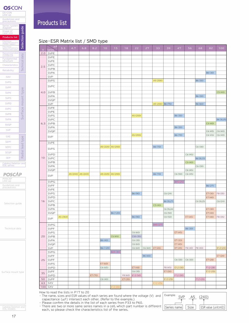
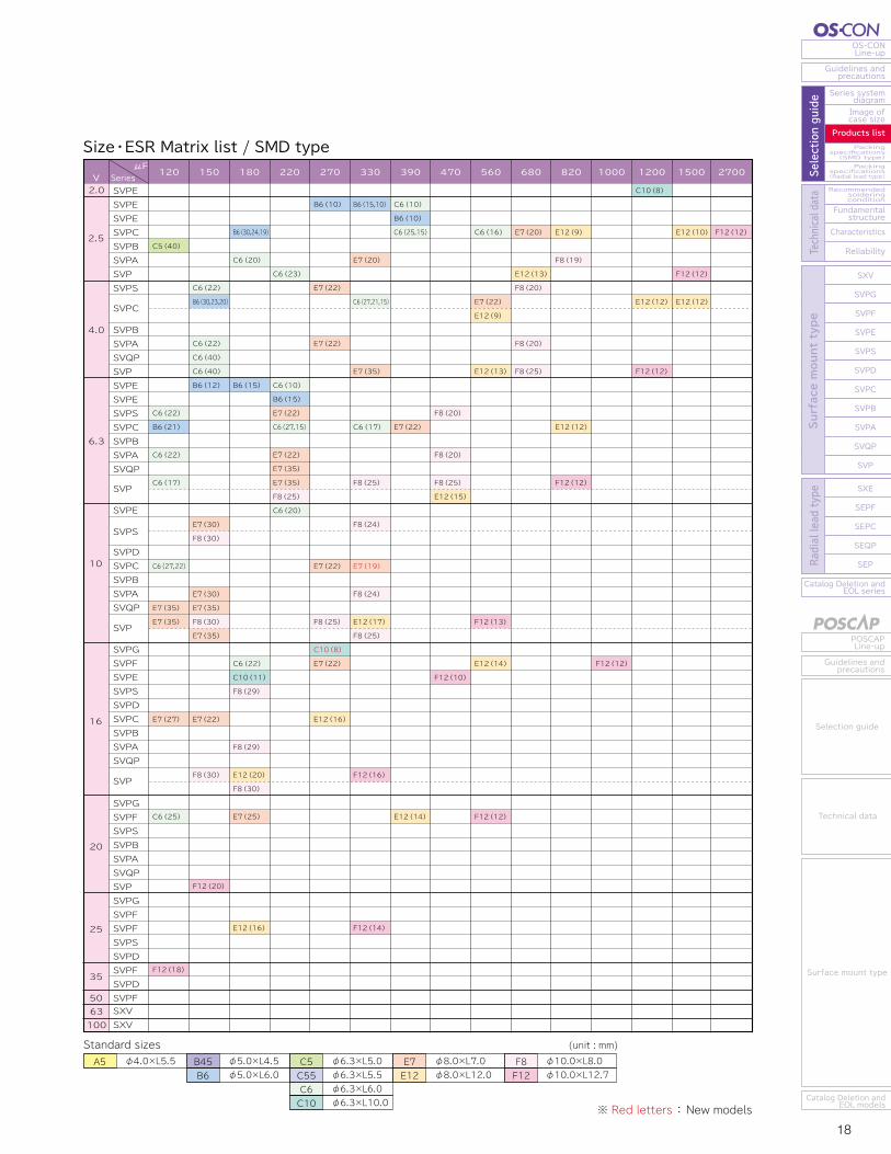
Products list
※ Red letters : New models
Size・ESR Matrix list / SMD type Size・ESR Matrix list / SMD type
Example SVP
Series name Size ESR value (unit:mΩ)
A5 (240)How to read the lists in P17 to 20・ The name, sizes and ESR values of each series are found where the voltage (V) and capacitance (μF) intersect each other. (Refer to the example.)・ Please confirm the details in the list of each series from P33 to P60.・ There are two or more same series names in a cell, which part number is differenteach, so please check the characteristics list of the series.
Standard sizes (unit : mm)φ4.0×L5.5A5 φ6.3×L5.0
φ6.3×L5.5φ6.3×L6.0φ6.3×L10.0
C5C55C6C10
φ5.0×L4.5φ5.0×L6.0
B45B6
φ8.0×L7.0φ8.0×L12.0
E7E12
φ10.0×L8.0φ10.0×L12.7
F8F12
VSVPESVPESVPESVPCSVPBSVPASVPSVPS
SVPC
SVPBSVPASVQPSVPSVPESVPESVPSSVPCSVPBSVPASVQP
SVP
SVPE
SVPS
SVPDSVPCSVPBSVPASVQP
SVP
SVPGSVPFSVPESVPSSVPDSVPCSVPBSVPASVQP
SVP
SVPGSVPFSVPSSVPBSVPASVQPSVPSVPGSVPFSVPFSVPSSVPDSVPFSVPDSVPF
A5(260)
A5(240) A5(240)
E7(70)
A5(220)
A5(220)
B6(40)
B6(120)
E7(60)
C6(65)
C6(40)
A5(200)
A5(200)
B6(120)
C5(45)
B45(30)
E12(40)
F8(60)
E7(35)
A5(200)
A5(200)
B6(90)
B6(90)
C6(60)
C55(35)
C6(35)
C6(60)
C6(60)
E7(48)
C6(35)
E12(50)
C6(60)
B6(40)
A5(200)
A5(200)
B6(70)
B6(70)
C5(40)
B45(27)
E7(45)
E12(25)
B6(70)
C6(24)
B6(35,27)
C6(35,24)
C6(50)
C6(50)
F8(45)
E7(30)
E12(25)
B6(30)
B6(30)
B6(70)
C6(50)
B45(25)
E7(45)
E7(33)
E7(45)
E7(45)
C6(30)
E12(30)
F12(30)
C6(45)
C5(40)
C6(45)
C6(45)
E7(45)
B6(30)
F8(40)
C6(30)
B6(30)
B6(30)
B6(60)
C6(30)
B6(30,23)
C6(30)
C6(30,25)
F8(40)
F12(20)
B6(30)
C5(40)
C6(45)
C6(45)
B6(27)
E7(30)
E7(40)
E7(30)
E7(40)
E7(40)
E7(28)
F12(28)
E12(20)
C5(40)
B6(30,25)
C6(40)
C6(40)
F8(35)
C6(24)
F8(35)
E12(24)
E7(24)
C5(40)
C6(22)
B6(21)
C6(22)
C6(17)
C6(27,22)
E7(35)
E7(35)
E7(27)
C6(25)
F12(18)
C6(22)
B6(30,23,20)
C6(22)
C6(40)
C6(40)
B6(12)
E7(30)
F8(30)
E7(30)
E7(35)
F8(30)
E7(35)
E7(22)
F8(30)
F12(20)
B6(30,24,19)
C6(20)
B6(15)
C6(22)
C10(11)
F8(29)
F8(29)
E12(20)
F8(30)
E7(25)
E12(16)
C6(23)
C6(10)
B6(15)
E7(22)
C6(27,15)
E7(22)
E7(35)
E7(35)
F8(25)
C6(20)
B6(10)
E7(22)
E7(22)
E7(22)
F8(25)
C10(8)
E7(22)
E12(16)
B6(15,10)
E7(20)
C6(27,21,15)
E7(35)
C6(17)
F8(25)
F8(24)
E7(19)
F8(24)
E12(17)
F8(25)
F12(16)
F12(14)
C6(10)
B6(10)
C6(25,15)
E7(22)
E12(14)
F8(20)
F8(20)
F8(25)
E12(15)
F12(10)
C6(16)
E7(22)
E12(9)
E12(13)
F12(13)
E12(14)
F12(12)
E7(20)
E12(13)
F8(20)
F8(20)
F8(25)
E12(9)
F8(19)
E12(12)
F12(12)
F12(12)
C10(8)
E12(12)
F12(12)
E12(10)
F12(12)
E12(12)
F12(12)
μFSeries 3.3 4.7 6.8 8.2 10 15 18 22 27 33 39 47 56 68 82 100
2.5
4.0
6.3
10
16
20
25
35
50
2.0V
SVPESVPESVPESVPCSVPBSVPASVPSVPS
SVPC
SVPBSVPASVQPSVPSVPESVPESVPSSVPCSVPBSVPASVQP
SVP
SVPE
SVPS
SVPDSVPCSVPBSVPASVQP
SVP
SVPGSVPFSVPESVPSSVPDSVPCSVPBSVPASVQP
SVP
SVPGSVPFSVPSSVPBSVPASVQPSVPSVPGSVPFSVPFSVPSSVPDSVPFSVPDSVPF
SXV SXVSXV SXV
μFSeries 120 150 180 220 270 330 390 470 560 680 820 1000 1200 1500 2700
2.5
4.0
6.3
10
16
20
25
35
50
2.0
63 63100 100
17 18
OS-CONLine-up
Guidelines andprecautions
Series systemdiagram
Recommendedsolderingcondition
Fundamentalstructure
Characteristics
Reliability
Catalog Deletion andEOL series
SXV
SVPG
SVPF
SVPE
SVPS
SVPD
SVPC
SVPB
SVPA
SVQP
SVP
SXE
SEPF
SEPC
SEQP
SEP
Image ofcase size
Products listPackingspecifications(SMD type)Packingspecifications(Radial lead type) Se
lection guide
Technical data
Surface mount type
Radial lead type
POSCAPLine-up
Guidelines andprecautions
Catalog Deletion andEOL models
Selection guide
Technical data
Surface mount type
Catalog Deletion andEOL series
SEP
SEQP
SEPC
SEPF
SXE
SXV
SVPG
SVPF
SVPE
SVPS
SVPD
SVPC
SVPB
SVPA
SVQP
SVP
Reliability
Characteristics
Fundamentalstructure
Recommendedsolderingcondition
Packingspecifications(Radial lead type)
Packingspecifications(SMD type)
Products list
Image ofcase size
Series systemdiagram
Guidelines andprecautions
OS-CONLine-up
Surface mount type
Radial lead type
Selection guide
Technical data
Guidelines andprecautions
POSCAPLine-up
Catalog Deletion andEOL models
Surface mount type
Technical data
Selection guide
Products list
※ Red letters : New models
Size・ESR Matrix list / SMD type Size・ESR Matrix list / SMD type
Example SVP
Series name Size ESR value (unit:mΩ)
A5 (240)How to read the lists in P17 to 20・ The name, sizes and ESR values of each series are found where the voltage (V) and capacitance (μF) intersect each other. (Refer to the example.)・ Please confirm the details in the list of each series from P33 to P60.・ There are two or more same series names in a cell, which part number is differenteach, so please check the characteristics list of the series.
Standard sizes (unit : mm)φ4.0×L5.5A5 φ6.3×L5.0
φ6.3×L5.5φ6.3×L6.0φ6.3×L10.0
C5C55C6C10
φ5.0×L4.5φ5.0×L6.0
B45B6
φ8.0×L7.0φ8.0×L12.0
E7E12
φ10.0×L8.0φ10.0×L12.7
F8F12
VSVPESVPESVPESVPCSVPBSVPASVPSVPS
SVPC
SVPBSVPASVQPSVPSVPESVPESVPSSVPCSVPBSVPASVQP
SVP
SVPE
SVPS
SVPDSVPCSVPBSVPASVQP
SVP
SVPGSVPFSVPESVPSSVPDSVPCSVPBSVPASVQP
SVP
SVPGSVPFSVPSSVPBSVPASVQPSVPSVPGSVPFSVPFSVPSSVPDSVPFSVPDSVPF
A5(260)
A5(240) A5(240)
E7(70)
A5(220)
A5(220)
B6(40)
B6(120)
E7(60)
C6(65)
C6(40)
A5(200)
A5(200)
B6(120)
C5(45)
B45(30)
E12(40)
F8(60)
E7(35)
A5(200)
A5(200)
B6(90)
B6(90)
C6(60)
C55(35)
C6(35)
C6(60)
C6(60)
E7(48)
C6(35)
E12(50)
C6(60)
B6(40)
A5(200)
A5(200)
B6(70)
B6(70)
C5(40)
B45(27)
E7(45)
E12(25)
B6(70)
C6(24)
B6(35,27)
C6(35,24)
C6(50)
C6(50)
F8(45)
E7(30)
E12(25)
B6(30)
B6(30)
B6(70)
C6(50)
B45(25)
E7(45)
E7(33)
E7(45)
E7(45)
C6(30)
E12(30)
F12(30)
C6(45)
C5(40)
C6(45)
C6(45)
E7(45)
B6(30)
F8(40)
C6(30)
B6(30)
B6(30)
B6(60)
C6(30)
B6(30,23)
C6(30)
C6(30,25)
F8(40)
F12(20)
B6(30)
C5(40)
C6(45)
C6(45)
B6(27)
E7(30)
E7(40)
E7(30)
E7(40)
E7(40)
E7(28)
F12(28)
E12(20)
C5(40)
B6(30,25)
C6(40)
C6(40)
F8(35)
C6(24)
F8(35)
E12(24)
E7(24)
C5(40)
C6(22)
B6(21)
C6(22)
C6(17)
C6(27,22)
E7(35)
E7(35)
E7(27)
C6(25)
F12(18)
C6(22)
B6(30,23,20)
C6(22)
C6(40)
C6(40)
B6(12)
E7(30)
F8(30)
E7(30)
E7(35)
F8(30)
E7(35)
E7(22)
F8(30)
F12(20)
B6(30,24,19)
C6(20)
B6(15)
C6(22)
C10(11)
F8(29)
F8(29)
E12(20)
F8(30)
E7(25)
E12(16)
C6(23)
C6(10)
B6(15)
E7(22)
C6(27,15)
E7(22)
E7(35)
E7(35)
F8(25)
C6(20)
B6(10)
E7(22)
E7(22)
E7(22)
F8(25)
C10(8)
E7(22)
E12(16)
B6(15,10)
E7(20)
C6(27,21,15)
E7(35)
C6(17)
F8(25)
F8(24)
E7(19)
F8(24)
E12(17)
F8(25)
F12(16)
F12(14)
C6(10)
B6(10)
C6(25,15)
E7(22)
E12(14)
F8(20)
F8(20)
F8(25)
E12(15)
F12(10)
C6(16)
E7(22)
E12(9)
E12(13)
F12(13)
E12(14)
F12(12)
E7(20)
E12(13)
F8(20)
F8(20)
F8(25)
E12(9)
F8(19)
E12(12)
F12(12)
F12(12)
C10(8)
E12(12)
F12(12)
E12(10)
F12(12)
E12(12)
F12(12)
μFSeries 3.3 4.7 6.8 8.2 10 15 18 22 27 33 39 47 56 68 82 100
2.5
4.0
6.3
10
16
20
25
35
50
2.0V
SVPESVPESVPESVPCSVPBSVPASVPSVPS
SVPC
SVPBSVPASVQPSVPSVPESVPESVPSSVPCSVPBSVPASVQP
SVP
SVPE
SVPS
SVPDSVPCSVPBSVPASVQP
SVP
SVPGSVPFSVPESVPSSVPDSVPCSVPBSVPASVQP
SVP
SVPGSVPFSVPSSVPBSVPASVQPSVPSVPGSVPFSVPFSVPSSVPDSVPFSVPDSVPF
SXV SXVSXV SXV
μFSeries 120 150 180 220 270 330 390 470 560 680 820 1000 1200 1500 2700
2.5
4.0
6.3
10
16
20
25
35
50
2.0
63 63100 100

19 20
OS-CONLine-up
Guidelines andprecautions
Series systemdiagram
Recommendedsolderingcondition
Fundamentalstructure
Characteristics
Reliability
Catalog Deletion andEOL series
SXV
SVPG
SVPF
SVPE
SVPS
SVPD
SVPC
SVPB
SVPA
SVQP
SVP
SXE
SEPF
SEPC
SEQP
SEP
Image ofcase size
Products listPackingspecifications(SMD type)Packingspecifications(Radial lead type) Se
lection guide
Technical data
Surface mount type
Radial lead type
POSCAPLine-up
Guidelines andprecautions
Catalog Deletion andEOL models
Selection guide
Technical data
Surface mount type
Catalog Deletion andEOL series
SEP
SEQP
SEPC
SEPF
SXE
SXV
SVPG
SVPF
SVPE
SVPS
SVPD
SVPC
SVPB
SVPA
SVQP
SVP
Reliability
Characteristics
Fundamentalstructure
Recommendedsolderingcondition
Packingspecifications(Radial lead type)
Packingspecifications(SMD type)
Products list
Image ofcase size
Series systemdiagram
Guidelines andprecautions
OS-CONLine-up
Surface mount type
Radial lead type
Selection guide
Technical data
Guidelines andprecautions
POSCAPLine-up
Catalog Deletion andEOL models
Surface mount type
Technical data
Selection guide
Products list
※ Red letters : New models
Size・ESR Matrix list / Radial lead type Size・ESR Matrix list / Radial lead type
V
SEPC
SEP
SEPC
SEQPSEP
SEPC
SEQPSEPSEPCSEQPSEPSEPF
SEPC
SEQPSEPSEPFSEQP
SEP
SEPFSEPFSEQPSEPFSXESXE
μFSeries 6.8 10 15 18 22 33 39 47 56 68 82 100 120 150
2.5
4.0
10
6.3
16
20
25
32
35
V
SEPC
SEP
SEPC
SEQPSEP
SEPC
SEQPSEPSEPCSEQPSEPSEPF
SEPC
SEQPSEPSEPFSEQP
SEP
SEPFSEPFSEQPSEPFSXESXE
μFSeries 180 220 270 330 390 470 560 680 820 1000 1200 1500 2700
2.5
4.0
10
6.3
16
20
25
32
3563 63100 100
E7(100) F8(80)
E12(40)
E12(50)
C6(60)
C6(60)
C55(35)
C6(35)
E7(45)
E12(25)
C6(50)
C6(50)
E7(30)
E7(45)
E7(45)
C6(45)
C6(45)
F8(40)
C6(30)
F8(40)
F8(40)
E7(25)
C6(45)
C6(45)
E7(40)
E7(40)
E7(28)
E12(20)
B9(7)
C6(40)
C6(24)
C9(10)
E12(24)
E12(24)
F8(35)
E7(35)
E7(35)
C6(25)
F13(18)
C6(40)
C6(40)
E7(35)
E7(35)
C55(30)
E7(22)
F8(30)
F8(30)
F13(20)
F13(20)
C6(22)
E9(10)
E12(16)
E12(20)
E12(20)
E7(25)
E12(16)
E7(35)
C55(18)
E7(13)
E7(22)
F8(25)
F8(25)
E7(22)
E12(11)
E9(10)
B9(7)
C9(7)
E7(35)
E7(35)
F8(25)
F8(25)
E12(17)
E12(17)
F13(16)
F13(16)
F13(14)
C6(10)
E12(14)
B9(7)
F8(25)
E9(8)
C9(7)
E13(8)
C7(20)
E12(15)
E12(15)
F13(10)
B9(7)
C9(7)
E9(8)
C6(10)
C9(7)
E9(7)
E13(7)
E12(13)
E12(13)
C9(7)
E9(7)
F13(13)
F13(13)
E12(14)
F13(12)
E12(13)
E13(7)
F8(25)
F8(25)
F13(7)
C9(7)
E7(8)
E9(5,7)
E13(7)
F13(7)
F13(12)
F13(12)
E9(7)
E7(18)
F13(12)
F13(12)
F13(12)
F13(12)
F13(10)
F13(10)
Standard sizes (unit : mm)φ5.0×L9.0B9 φ8.0×L7.0
φ8.0×L9.0φ8.0×L12.0φ8.0×L13.0
E7E9E12E13
φ6.3×L5.5φ6.3×L6.0φ6.3×L7.0φ6.3×L9.0
C55C6C7C9
φ10.0×L8.0φ8.0×L12.0
F8F13
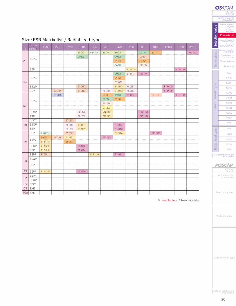
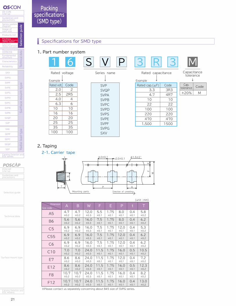
21 22
OS-CONLine-up
Guidelines andprecautions
Series systemdiagram
Recommendedsolderingcondition
Fundamentalstructure
Characteristics
Reliability
Catalog Deletion andEOL series
SXV
SVPG
SVPF
SVPE
SVPS
SVPD
SVPC
SVPB
SVPA
SVQP
SVP
SXE
SEPF
SEPC
SEQP
SEP
Image ofcase size
Products listPackingspecifications(SMD type)Packingspecifications(Radial lead type) Se
lection guide
Technical data
Surface mount type
Radial lead type
POSCAPLine-up
Guidelines andprecautions
Catalog Deletion andEOL models
Selection guide
Technical data
Surface mount type
Catalog Deletion andEOL series
SEP
SEQP
SEPC
SEPF
SXE
SXV
SVPG
SVPF
SVPE
SVPS
SVPD
SVPC
SVPB
SVPA
SVQP
SVP
Reliability
Characteristics
Fundamentalstructure
Recommendedsolderingcondition
Packingspecifications(Radial lead type)
Packingspecifications(SMD type)
Products list
Image ofcase size
Series systemdiagram
Guidelines andprecautions
OS-CONLine-up
Surface mount type
Radial lead type
Selection guide
Technical data
Guidelines andprecautions
POSCAPLine-up
Catalog Deletion andEOL models
Surface mount type
Technical data
Selection guide
Packingspecifications(SMD type)
1. Part number system
2. Taping2-1. Carrier tape
Rated voltage Series name Rated capacitance Capacitancetolerance
Rated volt. 2.0 2.5 4.0 6.31016202535100
Code2
2R5461016202535100
Rated cap.(μF)3.34.710 22 100 220 470
1,500
3R34R710221002204701500
Code Cap.tolerance±20%
Code
M
SVPSVQPSVPASVPBSVPCSVPDSVPSSVPESVPFSVPGSXV
ExampleExample
Mounting parts
T
t
B
2.0±0.14.0±0.1
EF
W
AP
Direction of unreeling
φ1.5±0.10
(unit : mm)
4.7±0.2
5.6±0.2
6.9±0.2
8.6±0.2
8.6±0.2
4.7±0.2
5.6±0.2
6.9±0.2
8.6±0.2
8.6±0.2
12.0±0.3
16.0±0.3
16.0±0.3
24.0±0.3
24.0±0.3
5.5±0.1
7.5±0.1
7.5±0.1
11.5±0.1
11.5±0.1
1.75±0.1
1.75±0.1
1.75±0.1
1.75±0.1
1.75±0.1
8.0±0.1
8.0±0.1
12.0±0.1
12.0±0.1
16.0±0.1
0.4±0.1
0.4±0.1
0.4±0.1
0.4±0.1
0.5±0.1
5.8±0.2
6.2±0.2
6.2±0.2
6.9±0.2
6.9±0.2
16.0±0.3
7.5±0.1
1.75±0.1
12.0±0.1
0.4±0.1
6.2±0.2
6.9±0.2
6.9±0.2
16.0±0.3
7.5±0.1
1.75±0.1
12.0±0.1
0.4±0.1
5.3±0.2
7.2±0.2
7.0±0.2
7.0±0.2
24.0±0.3
11.5±0.1
1.75±0.1
16.0±0.1
0.5±0.1
10.5±0.2
12.3±0.2
10.7±0.2
10.7±0.2
10.7±0.2
10.7±0.2
24.0±0.3
24.0±0.3
11.5±0.1
11.5±0.1
1.75±0.1
1.75±0.1
16.0±0.1
16.0±0.1
0.4±0.1
0.4±0.1
8.2±0.2
13.0±0.2
A B EFW t TPSize code
Dimension
1 6 S V P 3 R 3 M
2-2. Reel
2-3. Polarity
3. Minimum packing quantity and weightTaping type
Size code W1
13.0±0.5
17.0±0.5
25.0±0.5
W2
17.5±1.0
21.5±1.0
29.5±1.0
A5
B6, C5, C55, C6
C10, E7, F8, E12, F12
(unit : mm)
φ21±0.8R1.0
φ13±0.2
2±0.5
Direction of unreeling
φ380±2.0 W1
W2
φ80
±1.0
Dire
ction
of un
reeli
ng
Size code Quantity(pcs./Reel,φ380) Typical weight(g)2,0001,5001,3001,0001,000500
1,000400500400
700800800800800700
1,100800
1,0001,000
A5B6C5C55C6C10E7E12F8F12
A5
B6
C5
C55
C6
C10
E7
E12
F8
F12
Specifications for SMD type
※Please contact us separately concerning about B45 size of SVPG series.
※Please contact us separately concerning about B45 size of SVPG series.
※Please contact us separately concerning about B45 size of SVPG series.
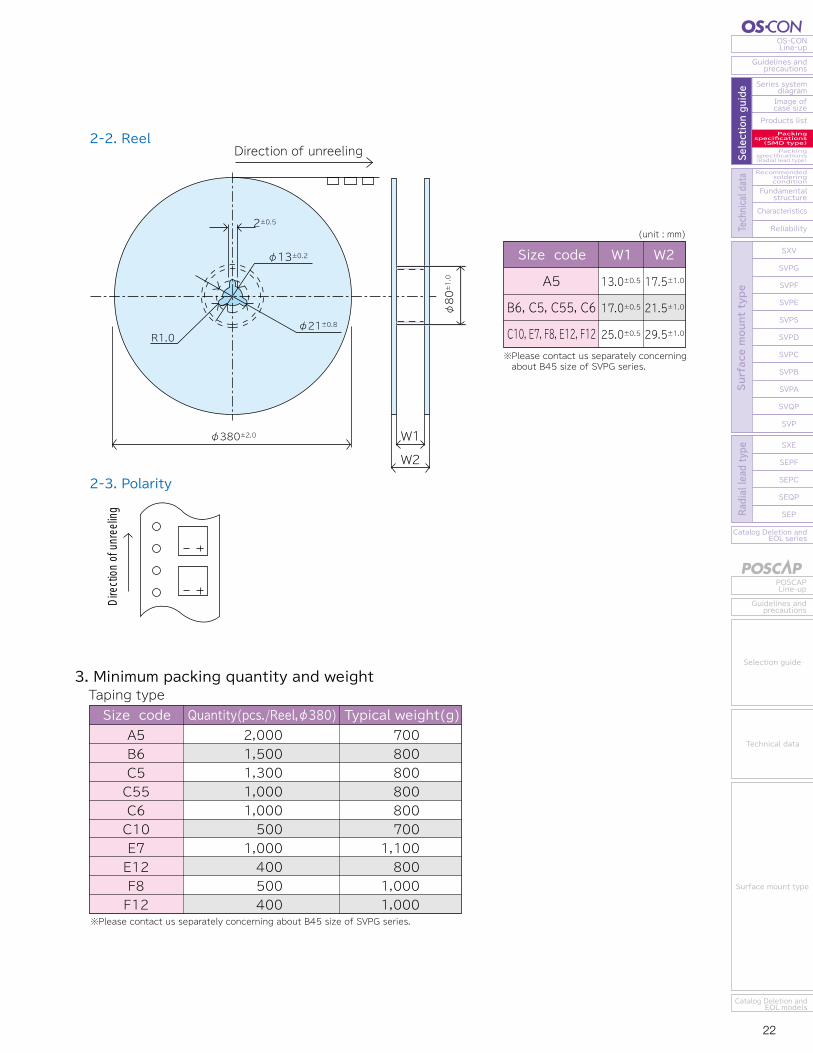
21 22
OS-CONLine-up
Guidelines andprecautions
Series systemdiagram
Recommendedsolderingcondition
Fundamentalstructure
Characteristics
Reliability
Catalog Deletion andEOL series
SXV
SVPG
SVPF
SVPE
SVPS
SVPD
SVPC
SVPB
SVPA
SVQP
SVP
SXE
SEPF
SEPC
SEQP
SEP
Image ofcase size
Products listPackingspecifications(SMD type)Packingspecifications(Radial lead type) Se
lection guide
Technical data
Surface mount type
Radial lead type
POSCAPLine-up
Guidelines andprecautions
Catalog Deletion andEOL models
Selection guide
Technical data
Surface mount type
Catalog Deletion andEOL series
SEP
SEQP
SEPC
SEPF
SXE
SXV
SVPG
SVPF
SVPE
SVPS
SVPD
SVPC
SVPB
SVPA
SVQP
SVP
Reliability
Characteristics
Fundamentalstructure
Recommendedsolderingcondition
Packingspecifications(Radial lead type)
Packingspecifications(SMD type)
Products list
Image ofcase size
Series systemdiagram
Guidelines andprecautions
OS-CONLine-up
Surface mount type
Radial lead type
Selection guide
Technical data
Guidelines andprecautions
POSCAPLine-up
Catalog Deletion andEOL models
Surface mount type
Technical data
Selection guide
Packingspecifications(SMD type)
1. Part number system
2. Taping2-1. Carrier tape
Rated voltage Series name Rated capacitance Capacitancetolerance
Rated volt. 2.0 2.5 4.0 6.31016202535100
Code2
2R5461016202535100
Rated cap.(μF)3.34.710 22 100 220 470
1,500
3R34R710221002204701500
Code Cap.tolerance±20%
Code
M
SVPSVQPSVPASVPBSVPCSVPDSVPSSVPESVPFSVPGSXV
ExampleExample
Mounting parts
T
t
B
2.0±0.14.0±0.1
EF
W
AP
Direction of unreeling
φ1.5±0.10
(unit : mm)
4.7±0.2
5.6±0.2
6.9±0.2
8.6±0.2
8.6±0.2
4.7±0.2
5.6±0.2
6.9±0.2
8.6±0.2
8.6±0.2
12.0±0.3
16.0±0.3
16.0±0.3
24.0±0.3
24.0±0.3
5.5±0.1
7.5±0.1
7.5±0.1
11.5±0.1
11.5±0.1
1.75±0.1
1.75±0.1
1.75±0.1
1.75±0.1
1.75±0.1
8.0±0.1
8.0±0.1
12.0±0.1
12.0±0.1
16.0±0.1
0.4±0.1
0.4±0.1
0.4±0.1
0.4±0.1
0.5±0.1
5.8±0.2
6.2±0.2
6.2±0.2
6.9±0.2
6.9±0.2
16.0±0.3
7.5±0.1
1.75±0.1
12.0±0.1
0.4±0.1
6.2±0.2
6.9±0.2
6.9±0.2
16.0±0.3
7.5±0.1
1.75±0.1
12.0±0.1
0.4±0.1
5.3±0.2
7.2±0.2
7.0±0.2
7.0±0.2
24.0±0.3
11.5±0.1
1.75±0.1
16.0±0.1
0.5±0.1
10.5±0.2
12.3±0.2
10.7±0.2
10.7±0.2
10.7±0.2
10.7±0.2
24.0±0.3
24.0±0.3
11.5±0.1
11.5±0.1
1.75±0.1
1.75±0.1
16.0±0.1
16.0±0.1
0.4±0.1
0.4±0.1
8.2±0.2
13.0±0.2
A B EFW t TPSize code
Dimension
1 6 S V P 3 R 3 M
2-2. Reel
2-3. Polarity
3. Minimum packing quantity and weightTaping type
Size code W1
13.0±0.5
17.0±0.5
25.0±0.5
W2
17.5±1.0
21.5±1.0
29.5±1.0
A5
B6, C5, C55, C6
C10, E7, F8, E12, F12
(unit : mm)
φ21±0.8R1.0
φ13±0.2
2±0.5
Direction of unreeling
φ380±2.0 W1
W2φ80
±1.0
Dire
ction
of un
reeli
ng
Size code Quantity(pcs./Reel,φ380) Typical weight(g)2,0001,5001,3001,0001,000500
1,000400500400
700800800800800700
1,100800
1,0001,000
A5B6C5C55C6C10E7E12F8F12
A5
B6
C5
C55
C6
C10
E7
E12
F8
F12
Specifications for SMD type
※Please contact us separately concerning about B45 size of SVPG series.
※Please contact us separately concerning about B45 size of SVPG series.
※Please contact us separately concerning about B45 size of SVPG series.
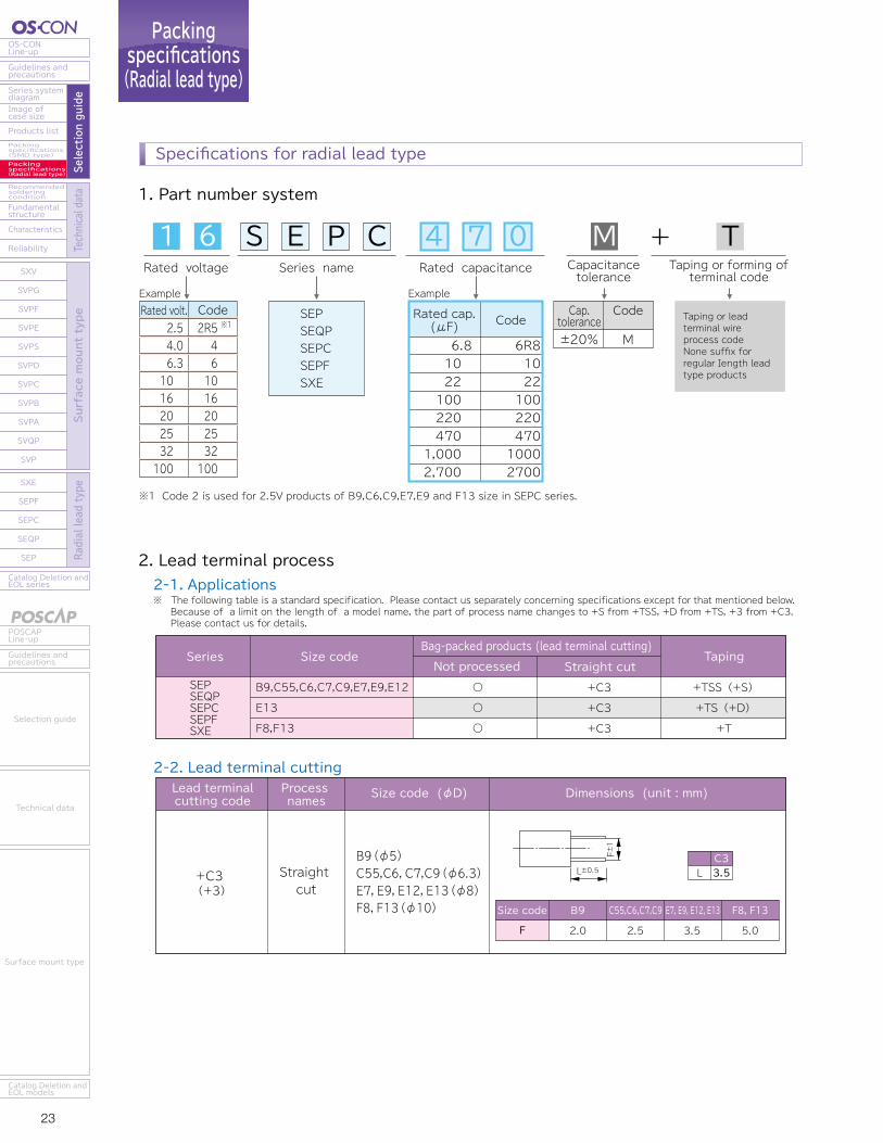
23 24
OS-CONLine-up
Guidelines andprecautions
Series systemdiagram
Recommendedsolderingcondition
Fundamentalstructure
Characteristics
Reliability
Catalog Deletion andEOL series
SXV
SVPG
SVPF
SVPE
SVPS
SVPD
SVPC
SVPB
SVPA
SVQP
SVP
SXE
SEPF
SEPC
SEQP
SEP
Image ofcase size
Products listPackingspecifications(SMD type)Packingspecifications(Radial lead type) Se
lection guide
Technical data
Surface mount type
Radial lead type
POSCAPLine-up
Guidelines andprecautions
Catalog Deletion andEOL models
Selection guide
Technical data
Surface mount type
Catalog Deletion andEOL series
SEP
SEQP
SEPC
SEPF
SXE
SXV
SVPG
SVPF
SVPE
SVPS
SVPD
SVPC
SVPB
SVPA
SVQP
SVP
Reliability
Characteristics
Fundamentalstructure
Recommendedsolderingcondition
Packingspecifications(Radial lead type)
Packingspecifications(SMD type)
Products list
Image ofcase size
Series systemdiagram
Guidelines andprecautions
OS-CONLine-up
Surface mount type
Radial lead type
Selection guide
Technical data
Guidelines andprecautions
POSCAPLine-up
Catalog Deletion andEOL models
Surface mount type
Technical data
Selection guide
Packingspecifications(Radial lead type)
Specifications for radial lead type
1. Part number system
Rated voltage
Rated volt. 2.5 4.0 6.31016202532100
Code2R5461016202532100
※1Cap.
tolerance±20%
Code
M
Taping or lead terminal wire process code None suffix for regular Iength lead type products
2-2. Lead terminal cutting
※1 Code 2 is used for 2.5V products of B9,C6,C9,E7,E9 and F13 size in SEPC series.
Process names
Straight cut
Size code (φD)Lead terminalcutting code
+C3(+3)
Dimensions (unit : mm)
LC33.5
F±1
L±0.5B9(φ5) C55,C6,C7,C9(φ6.3) E7,E9,E12,E13(φ8)F8,F13(φ10) Size code
F
B9
2.0
C55,C6,C7,C9
2.5
E7, E9, E12, E13
3.5
F8, F13
5.0
Series Size codeNot processed Straight cut
TapingBag-packed products (lead terminal cutting)
SEPSEQPSEPCSEPFSXE
B9,C55,C6,C7,C9,E7,E9,E12
E13
F8,F13
○
○
○
+C3
+C3
+C3
+TSS (+S)
+TS (+D)
+T
SEPSEQPSEPCSEPFSXE
Series name Capacitancetolerance
Taping or forming ofterminal code
Rated cap.(μF)6.8 10 22 100 220 470
1,000 2,700
6R8102210022047010002700
Code
ExampleExample
Rated capacitance
3. Minimum packing quantity and weight
2-3. Lead terminal taping F Size code (φD)Taping code Taping
φ 5φ 6.3φ 6.3φ 6.3φ 6.3φ 8φ 8φ 8φ 8φ10φ10
Quantity(pcs./Bag)500500500500500200200200200200200
Quantity(pcs./Bag)2,0001,5001,5001,5001,5001,0001,0001,0001,000500500
180150160210240110130200160180280
1,000650700920
1,000820900980
1,060890940
CodeTolerance
φ10φ8φ5φ6.3φ8
+T+TS(+D)
+TSS(+S)
F P P0 P1 P2 Δh W W0 W1 W2 H φD0 t L
5.03.52.02.53.5
12.712.712.712.712.7
12.712.712.712.712.7
3.854.605.355.104.60
6.356.356.356.356.35
00000
18.018.018.018.018.0
9.59.59.59.59.5
9.09.09.09.09.0
2.52.52.52.52.5
18.517.517.517.517.5
4.04.04.04.04.0
0.60.60.60.60.6
00000
11.011.011.011.011.0
±1.0 ±0.2 ±0.5 ±1.0 ±1.0 ±0.5 min. ±0.5 max ±0.75 ±0.2 ±0.3 max max+0.8-0.2
Processed type discrete lead terminals Zig-zag pack taping typeCase size
B9C55C6C7C9E7E9E12E13F8F13
Size code
F=5.0mm F8,F13(φ10) +T
F=3.5mm E13(φ8)
B9(φ5)C55,C6,C7,C9(φ6.3) E7,E9,E12(φ8)
+TS(+D)
F=2.0mmF=2.5mmF=3.5mm
+TSS(+S)
(unit : mm)
1 6 S E P C M T4 7 0
2. Lead terminal process2-1. Applications※ The following table is a standard specification. Please contact us separately concerning specifications except for that mentioned below. Because of a limit on the length of a model name, the part of process name changes to +S from +TSS, +D from +TS, +3 from +C3. Please contact us for details.
Typical weight(g) Typical weight(g)
t
W2
W1W0 W
H
P0 φD0
P2 P
L P1 F
h
Hold-down TapeCarrier Tape
t
W2
W1H
P0 φD0
P2 P
L P1 F
W0 W
h
Hold-down TapeCarrier Tape
t
W2
W1W0 W
H
P0 φD0
P2 P
L P1 F
h
Hold-down TapeCarrier Tape
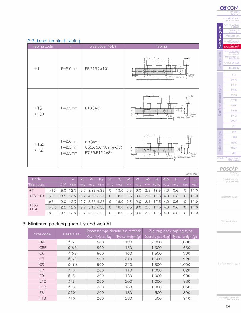

25 26
OS-CONLine-up
Guidelines andprecautions
Series systemdiagram
Recommendedsolderingcondition
Fundamentalstructure
Characteristics
Reliability
Catalog Deletion andEOL series
SXV
SVPG
SVPF
SVPE
SVPS
SVPD
SVPC
SVPB
SVPA
SVQP
SVP
SXE
SEPF
SEPC
SEQP
SEP
Image ofcase size
Products listPackingspecifications(SMD type)Packingspecifications(Radial lead type) Se
lection guide
Technical data
Surface mount type
Radial lead type
POSCAPLine-up
Guidelines andprecautions
Catalog Deletion andEOL models
Selection guide
Technical data
Surface mount type
Catalog Deletion andEOL series
SEP
SEQP
SEPC
SEPF
SXE
SXV
SVPG
SVPF
SVPE
SVPS
SVPD
SVPC
SVPB
SVPA
SVQP
SVP
Reliability
Characteristics
Fundamentalstructure
Recommendedsolderingcondition
Packingspecifications(Radial lead type)
Packingspecifications(SMD type)
Products list
Image ofcase size
Series systemdiagram
Guidelines andprecautions
OS-CONLine-up
Surface mount type
Radial lead type
Selection guide
Technical data
Guidelines andprecautions
POSCAPLine-up
Catalog Deletion andEOL models
Surface mount type
Technical data
Selection guide
Recommendedsolderingcondition
Fundamentalstructure
1. Basic structure of OS-CON
OS-CON has a basic construction similar to an aluminum electrolytic capacitor.A distinctive difference lies in electrolyte.
Aluminum electrolytic capacitor Liquid electrolyteSolid electrolyte
Separator sheet impregnated with electrolytic solution. Separator sheet impregnated with conductive polymer.
2. OS-CON Manufacturing Method
Aluminum electrolytic capacitorCharacteristics between OS-CON and aluminum electrolytic capacitor due to a difference in electrolyte
0.01S/cmConductivity
Reliability, lifespan
Temperature coefficient(for lifespan)
100S/cm・Difficult to lower ESR due to low conductivity・ESR augments, in particular, in low temperature conditions
・The highest electronic conductivity, realizing super low ESR.・ESR is stable in low temperature conditions
・Liquid electrolyte is evaporable at high temperature・Static capacitance is on the decline at high temperature・Limited lifespan resulting from dry-up・Major fluctuations in temperature characteristics
・Little evaporation due to solid electrolyte・Little decrease in static capacitance・Long lifespan even at high temperature・Very minor fluctuations in temperature characteristics
2 times by 10℃ reduction 10 times by 20℃ reduction105℃/2,000h→85℃/8,000h 105℃/2,000h→85℃/20,000h
【Radial lead type】 【Surface mount type】
The cycles of reflow soldering: Twice (max)
Tip of a soldering iron: 400±10℃ Working time: 5sec. max
The cycles of reflow soldering: Once (max)
Solderingcondition 260 + 5℃ or less 10 + 1 sec. or less
Temperature Time
2 times or less ※1
Preheating 120℃ or less(ambient temperature) 120 sec. or less 1 time
Flow number
※1. When soldering 2 times, total immersion time should be 10 + 1 sec. or less.
Peak temperature 250℃ lead free reflow soldering profile
Peak temperature 260℃ lead free reflow soldering profile
Soldering with a soldering iron
Flow soldering※Please contact us separately if you require life factor of SXV, SXE series.
Temperature on the
surface of capacitor
Time(sec.)
220℃230℃
200℃180℃150℃
250℃
120s max 60s max
50s max40s max
Temperature on the
surface of capacitor
220℃230℃
200℃180℃
150℃
260℃
120s max 60s max
50s max40s max
Time(sec.)
Surface mount typeRadial lead typeSealing rubber
Separator sheet
Anode aluminum foil
Cathode aluminum foil
Element
Plastic spacer
Aluminumcase
Sealingrubber
Cathode terminal
Cathode terminal
Dielectric oxidization layer (aluminum oxide)
Enlarged section diagram of the element
Electrolyte impregnating separator sheet (Electrolyte serves as the actual cathode.)
Anode terminal
Anode terminal
Cathode terminal
Anode terminal
Aluminum case
Separator sheet
Anode aluminum foil
Cathode aluminum foil
Packing and Shipping
Aging and Inspection
Marking
Rubber sealing (curl)
impregnation and polymerization
Forming and carbonization
Winding
Foil slitter
Forming
Aluminum etching foll
Conductive polymer
Rubber・Case
Lead wireSeparator Sheet
Packing and Shipping
Forming and Marking
Aging and Inspection
Rubber sealing (curl)
impregnation and polymerization
Forming and carbonization
Winding
Foil slitter
Forming
Aluminum etching foll
Conductive polymer
Rubber・Case
Plastic Spacer
Lead wireSeparator Sheet
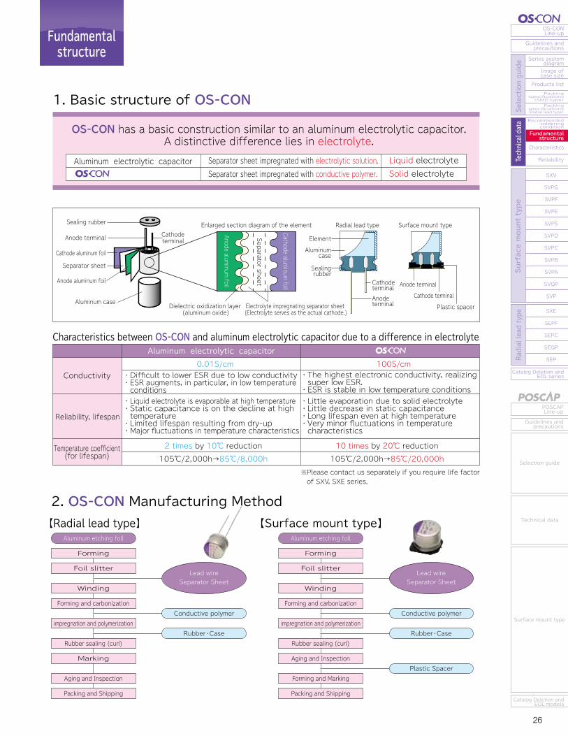
25 26
OS-CONLine-up
Guidelines andprecautions
Series systemdiagram
Recommendedsolderingcondition
Fundamentalstructure
Characteristics
Reliability
Catalog Deletion andEOL series
SXV
SVPG
SVPF
SVPE
SVPS
SVPD
SVPC
SVPB
SVPA
SVQP
SVP
SXE
SEPF
SEPC
SEQP
SEP
Image ofcase size
Products listPackingspecifications(SMD type)Packingspecifications(Radial lead type) Se
lection guide
Technical data
Surface mount type
Radial lead type
POSCAPLine-up
Guidelines andprecautions
Catalog Deletion andEOL models
Selection guide
Technical data
Surface mount type
Catalog Deletion andEOL series
SEP
SEQP
SEPC
SEPF
SXE
SXV
SVPG
SVPF
SVPE
SVPS
SVPD
SVPC
SVPB
SVPA
SVQP
SVP
Reliability
Characteristics
Fundamentalstructure
Recommendedsolderingcondition
Packingspecifications(Radial lead type)
Packingspecifications(SMD type)
Products list
Image ofcase size
Series systemdiagram
Guidelines andprecautions
OS-CONLine-up
Surface mount type
Radial lead type
Selection guide
Technical data
Guidelines andprecautions
POSCAPLine-up
Catalog Deletion andEOL models
Surface mount type
Technical data
Selection guide
Recommendedsolderingcondition
Fundamentalstructure
1. Basic structure of OS-CON
OS-CON has a basic construction similar to an aluminum electrolytic capacitor.A distinctive difference lies in electrolyte.
Aluminum electrolytic capacitor Liquid electrolyteSolid electrolyte
Separator sheet impregnated with electrolytic solution. Separator sheet impregnated with conductive polymer.
2. OS-CON Manufacturing Method
Aluminum electrolytic capacitorCharacteristics between OS-CON and aluminum electrolytic capacitor due to a difference in electrolyte
0.01S/cmConductivity
Reliability, lifespan
Temperature coefficient(for lifespan)
100S/cm・Difficult to lower ESR due to low conductivity・ESR augments, in particular, in low temperature conditions
・The highest electronic conductivity, realizing super low ESR.・ESR is stable in low temperature conditions
・Liquid electrolyte is evaporable at high temperature・Static capacitance is on the decline at high temperature・Limited lifespan resulting from dry-up・Major fluctuations in temperature characteristics
・Little evaporation due to solid electrolyte・Little decrease in static capacitance・Long lifespan even at high temperature・Very minor fluctuations in temperature characteristics
2 times by 10℃ reduction 10 times by 20℃ reduction105℃/2,000h→85℃/8,000h 105℃/2,000h→85℃/20,000h
【Radial lead type】 【Surface mount type】
The cycles of reflow soldering: Twice (max)
Tip of a soldering iron: 400±10℃ Working time: 5sec. max
The cycles of reflow soldering: Once (max)
Solderingcondition 260 + 5℃ or less 10 + 1 sec. or less
Temperature Time
2 times or less ※1
Preheating 120℃ or less(ambient temperature) 120 sec. or less 1 time
Flow number
※1. When soldering 2 times, total immersion time should be 10 + 1 sec. or less.
Peak temperature 250℃ lead free reflow soldering profile
Peak temperature 260℃ lead free reflow soldering profile
Soldering with a soldering iron
Flow soldering※Please contact us separately if you require life factor of SXV, SXE series.
Temperature on the
surface of capacitor
Time(sec.)
220℃230℃
200℃180℃150℃
250℃
120s max 60s max
50s max40s max
Temperature on the
surface of capacitor
220℃230℃
200℃180℃
150℃
260℃
120s max 60s max
50s max40s max
Time(sec.)
Surface mount typeRadial lead typeSealing rubber
Separator sheet
Anode aluminum foil
Cathode aluminum foil
Element
Plastic spacer
Aluminumcase
Sealingrubber
Cathode terminal
Cathode terminal
Dielectric oxidization layer (aluminum oxide)
Enlarged section diagram of the element
Electrolyte impregnating separator sheet (Electrolyte serves as the actual cathode.)
Anode terminal
Anode terminal
Cathode terminal
Anode terminal
Aluminum caseSeparator sheet
Anode aluminum foil
Cathode aluminum foil
Packing and Shipping
Aging and Inspection
Marking
Rubber sealing (curl)
impregnation and polymerization
Forming and carbonization
Winding
Foil slitter
Forming
Aluminum etching foll
Conductive polymer
Rubber・Case
Lead wireSeparator Sheet
Packing and Shipping
Forming and Marking
Aging and Inspection
Rubber sealing (curl)
impregnation and polymerization
Forming and carbonization
Winding
Foil slitter
Forming
Aluminum etching foll
Conductive polymer
Rubber・Case
Plastic Spacer
Lead wireSeparator Sheet
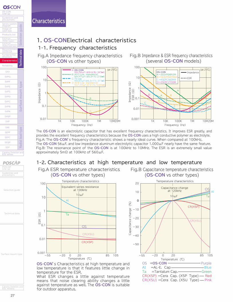
27 28
OS-CONLine-up
Guidelines andprecautions
Series systemdiagram
Recommendedsolderingcondition
Fundamentalstructure
Characteristics
Reliability
Catalog Deletion andEOL series
SXV
SVPG
SVPF
SVPE
SVPS
SVPD
SVPC
SVPB
SVPA
SVQP
SVP
SXE
SEPF
SEPC
SEQP
SEP
Image ofcase size
Products listPackingspecifications(SMD type)Packingspecifications(Radial lead type) Se
lection guide
Technical data
Surface mount type
Radial lead type
POSCAPLine-up
Guidelines andprecautions
Catalog Deletion andEOL models
Selection guide
Technical data
Surface mount type
Catalog Deletion andEOL series
SEP
SEQP
SEPC
SEPF
SXE
SXV
SVPG
SVPF
SVPE
SVPS
SVPD
SVPC
SVPB
SVPA
SVQP
SVP
Reliability
Characteristics
Fundamentalstructure
Recommendedsolderingcondition
Packingspecifications(Radial lead type)
Packingspecifications(SMD type)
Products list
Image ofcase size
Series systemdiagram
Guidelines andprecautions
OS-CONLine-up
Surface mount type
Radial lead type
Selection guide
Technical data
Guidelines andprecautions
POSCAPLine-up
Catalog Deletion andEOL models
Surface mount type
Technical data
Selection guide
Characteristics
1-2. Characteristics at high temperature and low temperatureFig.A ESR temperature characteristics (OS-CON vs other types)
Fig.B Capacitance temperature characteristics (OS-CON vs other types)
1-3. Bias characteristics
Multi-layer ceramic capacitor (25V/4.7μF) OS-CON(25SVPD10M)
(a) Capacitance
(b) Impedance, ESRBias characteristics of OS-CON & ceramic capacitors
1. OS-CONElectrical characteristics
The OS-CON is an electrolytic capacitor that has excellent frequency characteristics. It improves ESR greatly, and provides the excellent frequency characteristics because the OS-CON uses a high conductive polymer as electrolyte.Fig.A: The OS-CON’s frequency characteristic shows a nearly ideal curve. When compared at 100kHz, The OS-CON 56μF, and low impedance aluminum electrolytic capacitor 1,000μF nearly have the same feature.Fig.B: The resonance point of the OS-CON is at 100kHz to 10MHz. The ESR is an extremely small value approximately 5mΩ at 100kHz of 560μF.
Fig.A Impedance frequency characteristics (OS-CON vs other types)
Fig.B Impedance & ESR frequency characteristics (several OS-CON models)
1-1. Frequency characteristics
Frequency(Hz)
100
10
1
0.1
0.01
0.0011K 10K 100K 1M 10M20M
Impedance(Ω)
ESR(Ω)
Impedance
ESR
A B
B
DA
CC
D
A→35SVPD8R2MB→16SVPA82MAAC→4SEPC560MXD→2SEPC2700M
(25℃)(at 25℃)
Frequency(Hz)
100
10
1
0.1
0.011K 10K 100K 1M 10M20M
Impedance(Ω)
A:OS-CON
B:AI-E(Low impedance)16V/56μF(φ8×6.9L:347 )
16V/47μF(φ6.3×7L:218 )C:Ta-cap16V/47μF(φ6.3×11L:311 )
D:AI-E(Low impedance)16V/1,000μF(φ16×25L:5,024 )
AD
C
B
(25℃)(at 25℃)
OS =OS-CON AI =AL-E. Cap Ta =Tantalum Cap. CR(X5P) =Cera Cap. (X5P Type) CR(X5U) =Cera Cap. (X5U Type)
PurpleBlueGreenRed Pink
OS-CON’s Characteristics at high temperature and low temperature is that it features little change in temperature for the ESR.What ESR changes a little against temperature means that noise clearing ability changes a little against temperature as well. The OS-CON is suitable for outdoor apparatus.
When voltage is applied to ceramic capacitors, they show a bias characteristics where static capacitance is reduced. Our OS-CON product, however, will show no reduction in capaci-tance for applied voltage within its rating.
ESR & impedance of ceramic capacitors change largely between 300kHz to 1MHz. As for OS-CON, neither ESR nor impedance changes.
OS.1 =OS-CON(10SVP10M) OS.2 =OS-CON(25SVPD10M) CR(X5P) =Cera Cap. (X5P Type ; 10V/10μF)CR(X5U) =Cera Cap. (X5U Type ; 50V/10μF)
PurpleLight Purple
Red
Pink
0V bias 0V bias
20V bias20V biasMulti-layer ceramic capacitor (25V/4.7μF) OS-CON (25SVPD10M)
ESR, Impedance(Ω)
10 100Frequency(kHz)
1,000 10,000
0.01
0.001
0.1
1
10
100
Z
ESR
ESR, Impedance(Ω)
10 100Frequency(kHz)
1,000 10,000
0.01
0.001
0.1
1
10
100
Z
ESR ESR, Impedance(Ω)
10 100Frequency(kHz)
1,000 10,000
0.01
0.001
0.1
1
10
100
Z
ESR
ESR, Impedance(Ω)
10 100Frequency(kHz)
1,000 10,000
0.01
0.001
0.1
1
10
100
Z
ESR
Temperature (℃) -55 -20 20 85 1050
ESR (Ω)
20
10
0
-10
-20
-30
-40
-50
Temperature characteristics
Capacitance changeat 120kHz
Temperature (℃)
10μF
-55 -20 20 85 1050
AlTa
CR(X5U)
CR(X5P)
Capacitance change (%) 0
OS100
Temperature characteristics
Equivalent series resistanceat 100kHz10μF
10
1
0.1
0.01
0.001
Al
Ta
OS
CR(X5U)
CR(X5P)
0
-10
-20
-300 10 20 30 35
Bias voltage characteristics
Capacitance changeat 120Hz
10μF
CR(X5P) CR(X5U)
OS.1 OS.2
Capacitance change (%)
Bias voltage (V)
OS-CON
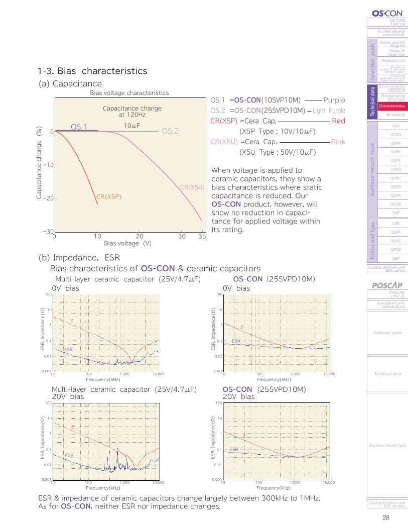
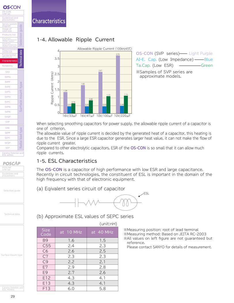
29 30
OS-CONLine-up
Guidelines andprecautions
Series systemdiagram
Recommendedsolderingcondition
Fundamentalstructure
Characteristics
Reliability
Catalog Deletion andEOL series
SXV
SVPG
SVPF
SVPE
SVPS
SVPD
SVPC
SVPB
SVPA
SVQP
SVP
SXE
SEPF
SEPC
SEQP
SEP
Image ofcase size
Products listPackingspecifications(SMD type)Packingspecifications(Radial lead type) Se
lection guide
Technical data
Surface mount type
Radial lead type
POSCAPLine-up
Guidelines andprecautions
Catalog Deletion andEOL models
Selection guide
Technical data
Surface mount type
Catalog Deletion andEOL series
SEP
SEQP
SEPC
SEPF
SXE
SXV
SVPG
SVPF
SVPE
SVPS
SVPD
SVPC
SVPB
SVPA
SVQP
SVP
Reliability
Characteristics
Fundamentalstructure
Recommendedsolderingcondition
Packingspecifications(Radial lead type)
Packingspecifications(SMD type)
Products list
Image ofcase size
Series systemdiagram
Guidelines andprecautions
OS-CONLine-up
Surface mount type
Radial lead type
Selection guide
Technical data
Guidelines andprecautions
POSCAPLine-up
Catalog Deletion andEOL models
Surface mount type
Technical data
Selection guide
※Guaranteed temperature of the OS-CON is 105℃, except for SEQP, SVQP and SVPD series.※Time is an estimate, not guaranteed.
The dielectric substance of the OS-CON is a non-conductive oxide film that has formed on the surface of an anode aluminum foil. Since the oxide film is solid and thin, leakage current may temporarily increase if micro cracks are generated by external stress (i.e. mechanical, thermal, electrical) [see figure (b)]. When this happens, the leakage current generates Joule heat [see figure (c)] and with this heat the electrolyte turns non-conductive and insulates the outlet of the leakage path [see figure (d)]. The leakage current from the micro cracks is thus suppressed through this function. This is known as "self-healing mechanism."
The decrease in capacitance of the OS-CON depends on temperature.The left figure shows the speed of capacitance decrease at each temperature. This graph indicates that temperature coefficient of the OS-CON lifetime is 10 times by 20℃ reduction.Compared with this, aluminum capacitor lifetime is 2 times by 10℃ reduction.
The OS-CON is a capacitor of high performance with low ESR and large capacitance.Recently in circuit technologies, the constituent of ESL is important in the domain of the high frequency with that of electronic equipment.
When selecting smoothing capacitors for power supply, the allowable ripple current of a capacitor is one of criterion.The allowable value of ripple current is decided by the generated heat of a capacitor, this heating is due to the ESR. Since a large ESR capacitor generates larger heat value, it can not make the flow of ripple current greater.Compared to other electrolytic capacitors, ESR of the OS-CON is so small that it can allow much ripple currents.
Characteristics Reliability
1. Temperature acceleration test (Endurance)
2. Self-Healing Mechanism
-10
-1
100Time(h)
10 1,000
Capacitance change(%)
Capacitance changeat 120Hz10V/22μF
155℃
145℃ 135℃ 125℃
105℃
85℃
70℃
Aluminum electrolytic capacitorOS-CON2,000h6,324h20,000h63,245h
105℃ 95℃ 85℃ 75℃
⇒⇒⇒⇒
2,000h4,000h8,000h16,000h
105℃ 95℃ 85℃ 75℃
⇒⇒⇒⇒
1-4. Allowable Ripple Current
1-5. ESL Characteristics
ESL
1.62.42.62.32.22.92.74.34.36.0
1.52.32.52.32.12.82.64.14.15.8
B9C55C6C7C9E7E9E12E13F13
(unit:nH)SizeCode
3.5
4
3
2.5
2
1.5
1
0.5
0
Allowable Ripple Current(100kHz45℃)
16V/33μF
Ripple Current(Arms)
0.450.74
16V/47μF
0.45
0.84
10V/100μF
0.45
1.10
10V/220μF
1.39
1.80
2.67
3.74
0.48
1.15
at 10 MHz at 40 MHz
(a) Eqivalent series circuit of capacitor
(b) Approximate ESL values of SEPC series
OS-CON (SVP series) Light PurpleAI-E. Cap. (Low Impedance) BlueTa.Cap. (Low ESR) Green※Samples of SVP series are approximate models.
※Measuring position: root of lead terminal※Measuring method: Based on JEITA RC-2003※All values on left figure are not guaranteed but reference. Please contact SANYO for details of measurement.
Though the OS-CON and an aluminum electrolytic capacitors are guaranteed on 2,000 hours at 105℃, the life span results in differences as temperature drops.The OS-CON has a longer life span compared with an aluminum electrolytic capacitor.
Estimation of life time
(a) (b) (c) (d)
Electrolyte
Anode aluminum foil
Dielectric oxide film
Heating by Joule heat
Leakage currentLeakage current
Insulation of electrolyte, a part of heating Crack generated by
an external impact
31 32
OS-CONLine-up
Guidelines andprecautions
Series systemdiagram
Recommendedsolderingcondition
Fundamentalstructure
Characteristics
Reliability
Catalog Deletion andEOL series
SXV
SVPG
SVPF
SVPE
SVPS
SVPD
SVPC
SVPB
SVPA
SVQP
SVP
SXE
SEPF
SEPC
SEQP
SEP
Image ofcase size
Products listPackingspecifications(SMD type)Packingspecifications(Radial lead type) Se
lection guide
Technical data
Surface mount type
Radial lead type
POSCAPLine-up
Guidelines andprecautions
Catalog Deletion andEOL models
Selection guide
Technical data
Surface mount type
Catalog Deletion andEOL series
SEP
SEQP
SEPC
SEPF
SXE
SXV
SVPG
SVPF
SVPE
SVPS
SVPD
SVPC
SVPB
SVPA
SVQP
SVP
Reliability
Characteristics
Fundamentalstructure
Recommendedsolderingcondition
Packingspecifications(Radial lead type)
Packingspecifications(SMD type)
Products list
Image ofcase size
Series systemdiagram
Guidelines andprecautions
OS-CONLine-up
Surface mount type
Radial lead type
Selection guide
Technical data
Guidelines andprecautions
POSCAPLine-up
Catalog Deletion andEOL models
Surface mount type
Technical data
Selection guide
The capacitance of the OS-CON is getting smaller as time goes with endurance test.This means wear-failure of the OS-CON is open mode, which is a main failure factor.The life time is different by each operating temperature and self-heating by ripple current.The following formula is used to to estimate the presumptive lifetime of the OS-CON at ambient temperatureTx (℃).The result of the following estimation is not guaranteed but presumptive values based on actual measurement. The estimated life-span is limited up to 15 years.
Reliability
3. Reliability presumption of life for the OS-CON
3-1. Calculation formula of estimated life expectancy
Lx : Life expectance (h) in actual use (temperature Tx) Lo : Guaranteed (h) at maximum temperature in useTo : Maximum operating temperature (℃)Tx : Temperature in actual use (ambient temperature of the OS-CON) (℃)Please contact us separately about estimated life expectancy of new series (SXV, SXE series) and products (SVQP, SVPD, SEQP series) guaranteed at 125℃.
Lx=Lo×10
4. Conductive polymer type (16SVP39M)4-1. Endurance (105°C, 16V applied)
4-2. Damp heat (60°C90% RH, without load)
Characteristics on Endurance
Characteristics on damp heat
To-Tx20
Self-heating temperature when applied the rated ripple current
※The estimated life expectancy of conductive polymer electrolyte type can be calculated without consideration of self-heating under application of the ripple current ※SVPS series: Self-heating temperature when applied the allowable ripple current.
Except for A5, B6A5,B6AllAll
approx. 20℃approx. 10℃approx. 20℃approx. 2℃
sizeseries Self-heatingSVP, SVPA, SVPC, SVPS SVP, SVPA, SVPC, SVPSSVPB, SVPE, SVPF, SVPG, SXV, SEP, SEPC, SEPF, SXESVQP, SEQP, SVPD
※
※
1
10
100
0.10 5,000 10,000
0 5,000 10,000
0 5,000 10,000
0 5,000 10,000
Leakage current
(μA at 16V30s)
2040
8060
100
0ESR(mΩ at 100kHz)
0.020.04
0.080.06
0.1
0tanδ(at 120Hz)
-10
0
10
20
-20
Capacitance change(%)
1
10
100
0.10 5,000 10,000
0 5,000 10,000
0 5,000 10,000
0 5,000 10,000
Leakage current
(μA at 16V30s)
20
20
40
8060
100
0ESR(mΩ at 100kHz)
0.020.04
0.080.06
0.1
0tanδ(at 120Hz)
-10
0
10
-20
Capacitance change(%)
Little change in characteristics can be seen after 10,000h hours in a high temperature and damp heat environment because of the excellent thermal stability of conductive polymer.
Little change in characteristics can be seen after 10,000 hours because of adoption of conductive polymer that excels in thermal stability.
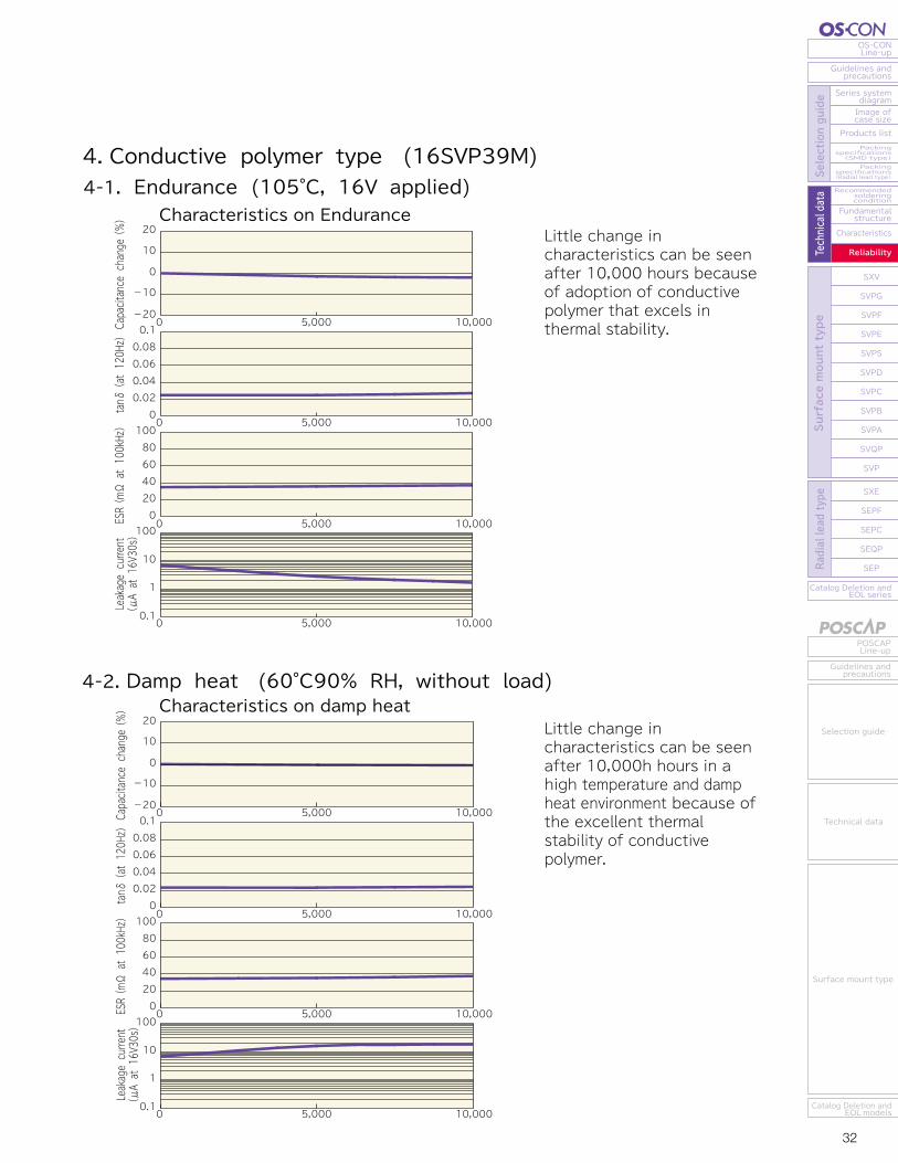
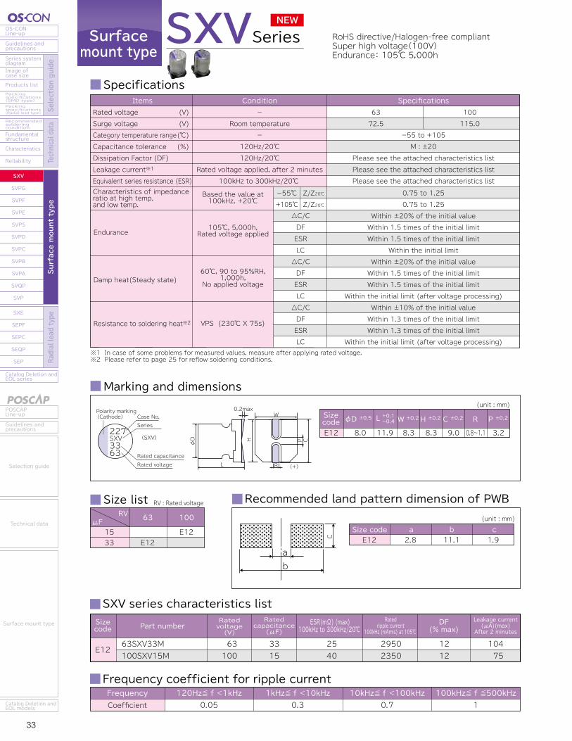
33 34
OS-CONLine-up
Guidelines andprecautions
Series systemdiagram
Recommendedsolderingcondition
Fundamentalstructure
Characteristics
Reliability
Catalog Deletion andEOL series
SXV
SVPG
SVPF
SVPE
SVPS
SVPD
SVPC
SVPB
SVPA
SVQP
SVP
SXE
SEPF
SEPC
SEQP
SEP
Image ofcase size
Products listPackingspecifications(SMD type)Packingspecifications(Radial lead type) Se
lection guide
Technical data
Surface mount type
Radial lead type
POSCAPLine-up
Guidelines andprecautions
Catalog Deletion andEOL models
Selection guide
Technical data
Surface mount type
Catalog Deletion andEOL series
SEP
SEQP
SEPC
SEPF
SXE
SXV
SVPG
SVPF
SVPE
SVPS
SVPD
SVPC
SVPB
SVPA
SVQP
SVP
Reliability
Characteristics
Fundamentalstructure
Recommendedsolderingcondition
Packingspecifications(Radial lead type)
Packingspecifications(SMD type)
Products list
Image ofcase size
Series systemdiagram
Guidelines andprecautions
OS-CONLine-up
Surface mount type
Radial lead type
Selection guide
Technical data
Guidelines andprecautions
POSCAPLine-up
Catalog Deletion andEOL models
Surface mount type
Technical data
Selection guide
Surfacemount type
RoHS directive/Halogen-free compliantSuper high voltage(100V)Endurance: 105℃ 5,000h
SVPGSeries HS directive/Halogen-free compliantLow ESR(8mΩ)High rated ripple current(5,800mArms)
SXVSeries
Marking and dimensions
Specifications
(unit : mm)
φD ±0.5 W ±0.2 H ±0.2 C ±0.2 R P ±0.2L +0.1-0.4
E12 8.0 11.9 8.3 8.3 9.0 0.8~1.1 3.2
φD
L
P
R
C
W0.2max
H
(+)
227SXV3363
Case No.Polarity marking(Cathode)
Series
Rated capacitanceRated voltage
Frequency coefficient for ripple currentFrequencyCoefficient
120Hz≦ f <1kHz0.05
1kHz≦ f <10kHz0.3
10kHz≦ f <100kHz0.7
100kHz≦ f ≦500kHz1
(SXV)
SXV series characteristics list
E1263SXV33M100SXV15M
63100
33 15
2540
29502350
1212
104 75
Sizecode
ESR(mΩ) (max)100kHz to 300kHz/20℃
Ratedripple current
100kHz (mArms) at 105℃ DF
(% max)Ratedvoltage(V)
Leakage current (μA)(max) After 2 minutes
Part numberRated
capacitance(μF)
Size list RV : Rated voltageRV
μF 63 100
1533 E12
E12
Recommended land pattern dimension of PWB
Size codeE12
a b c2.8 11.1 1.9
(unit : mm)
C
ab
Marking and dimensions
Specifications
(unit : mm)
φD ±0.5 W ±0.2 H ±0.2 C ±0.2 R P ±0.2Sizecode L +0.1-0.4
B45C10
5.06.3
4.49.9
5.36.6
5.36.6
6.07.3
0.6~0.80.6~0.8
1.42.1φ
D
L
P
R
C
W0.2max
H
(+)
003PG1525
Case No.Polarity marking(Cathode)
Series
Rated capacitanceRated voltage
Frequency coefficient for ripple currentFrequencyCoefficient
120Hz≦ f <1kHz0.05
1kHz≦ f <10kHz0.3
10kHz≦ f <100kHz0.7
100kHz≦ f ≦500kHz1
(PG)
SVPG series characteristics list
B45
C10
25SVPG15M20SVPG33M16SVPG47M16SVPG270M
25201616
153347270
3027258
2800300032005800
12121212
75132150864
Sizecode
ESR(mΩ) (max)100kHz to 300kHz/20℃
Ratedripple current
100kHz (mArms) at 105℃DF
(% max)Ratedvoltage(V)
Leakage current (μA)(max) After 2 minutes
Part numberRated
capacitance(μF)
Size list RV : Rated voltageRV
μF 16 20
153347270
B45C10
B45
25
B45
Recommended land pattern dimension of PWB
Size codeB45C10
a b c1.42.1
7.49.1
1.61.6
(unit : mm)
C
ab
NEW NEW
※1 In case of some problems for measured values, measure after applying rated voltage.※2 Please refer to page 25 for reflow soldering conditions.
Endurance
Characteristics of impedanceratio at high temp. and low temp.
Damp heat(Steady state)
Resistance to soldering heat※2
△C/CDFESRLC△C/CDFESRLC△C/CDFESRLC
-55℃+105℃
Z/Z20℃Z/Z20℃
-55 to +105M : ±20
Please see the attached characteristics listPlease see the attached characteristics listPlease see the attached characteristics list
6372.5
100115.0
SpecificationsItemsRated voltageSurge voltageCategory temperature rangeCapacitance toleranceDissipation Factor (DF)Leakage current※1
Equivalent series resistance (ESR)
(V)(V)(℃)(%)
105℃, 5,000h,Rated voltage applied
Based the value at100kHz, +20℃
60℃, 90 to 95%RH,1,000h,
No applied voltage
VPS (230℃ X 75s)
Condition-
Room temperature-
120Hz/20℃120Hz/20℃
Rated voltage applied, after 2 minutes100kHz to 300kHz/20℃
0.75 to 1.250.75 to 1.25
Within ±20% of the initial valueWithin 1.5 times of the initial limitWithin 1.5 times of the initial limit
Within the initial limitWithin ±20% of the initial valueWithin 1.5 times of the initial limitWithin 1.5 times of the initial limit
Within the initial limit (after voltage processing)Within ±10% of the initial valueWithin 1.3 times of the initial limitWithin 1.3 times of the initial limit
Within the initial limit (after voltage processing)
Sizecode
※1 In case of some problems for measured values, measure after applying rated voltage.※2 Please refer to page 25 for reflow soldering conditions.
Endurance
Characteristics of impedanceratio at high temp. and low temp.
Damp heat(Steady state)
Resistance to soldering heat※2
△C/CDFESRLC△C/CDFESRLC△C/CDFESRLC
-55℃+105℃
Z/Z20℃Z/Z20℃
-55 to +105M : ±20
Please see the attached characteristics listPlease see the attached characteristics listPlease see the attached characteristics list
1618
2023
2529
SpecificationsItemsRated voltageSurge voltageCategory temperature rangeCapacitance toleranceDissipation Factor (DF)Leakage current※1
Equivalent series resistance (ESR)
(V)(V)(℃)(%)
105℃, 5,000h,Rated voltage applied
Based the value at100kHz, +20℃
60℃, 90 to 95%RH,1,000h,
No applied voltage
VPS (230℃ X 75s)
Condition-
Room temperature-
120Hz/20℃120Hz/20℃
Rated voltage applied, after 2 minutes100kHz to 300kHz/20℃
0.75 to 1.250.75 to 1.25
Within ±20% of the initial valueWithin 1.5 times of the initial limitWithin 1.5 times of the initial limit
Within the initial limitWithin ±20% of the initial valueWithin 1.5 times of the initial limitWithin 1.5 times of the initial limit
Within the initial limit (after voltage processing)Within ±10% of the initial valueWithin 1.3 times of the initial limitWithin 1.3 times of the initial limit
Within the initial limit (after voltage processing)
Surfacemount type
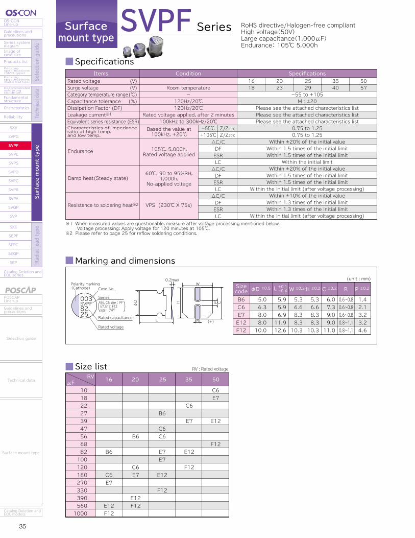
35 36
OS-CONLine-up
Guidelines andprecautions
Series systemdiagram
Recommendedsolderingcondition
Fundamentalstructure
Characteristics
Reliability
Catalog Deletion andEOL series
SXV
SVPG
SVPF
SVPE
SVPS
SVPD
SVPC
SVPB
SVPA
SVQP
SVP
SXE
SEPF
SEPC
SEQP
SEP
Image ofcase size
Products listPackingspecifications(SMD type)Packingspecifications(Radial lead type) Se
lection guide
Technical data
Surface mount type
Radial lead type
POSCAPLine-up
Guidelines andprecautions
Catalog Deletion andEOL models
Selection guide
Technical data
Surface mount type
Catalog Deletion andEOL series
SEP
SEQP
SEPC
SEPF
SXE
SXV
SVPG
SVPF
SVPE
SVPS
SVPD
SVPC
SVPB
SVPA
SVQP
SVP
Reliability
Characteristics
Fundamentalstructure
Recommendedsolderingcondition
Packingspecifications(Radial lead type)
Packingspecifications(SMD type)
Products list
Image ofcase size
Series systemdiagram
Guidelines andprecautions
OS-CONLine-up
Surface mount type
Radial lead type
Selection guide
Technical data
Guidelines andprecautions
POSCAPLine-up
Catalog Deletion andEOL models
Surface mount type
Technical data
Selection guide
Surfacemount type
RoHS directive/Halogen-free compliantHigh voltage(50V)Large capacitance(1,000μF)Endurance: 105℃ 5,000h
FrequencyCoefficient
120Hz≦ f <1kHz0.05
1kHz≦ f <10kHz0.3
10kHz≦ f <100kHz0.7
100kHz≦ f ≦500kHz1
SVPF Series
Specifications
Frequency coefficient for ripple current
Recommended land pattern dimension of PWB
Size list
(unit : mm)
φD ±0.5 W ±0.2 H ±0.2 C ±0.2 R P ±0.2Sizecode L +0.1-0.4
B6C6E7E12F12
5.06.38.08.010.0
5.95.96.911.912.6
5.36.68.38.310.3
5.36.68.38.310.3
6.07.39.09.011.0
0.6~0.80.6~0.80.6~0.80.8~1.10.8~1.1
1.42.13.23.24.6
※1 When measured values are questionable, measure after voltage processing mentioned below. Voltage processing: Apply voltage for 120 minutes at 105℃. ※2 Please refer to page 25 for reflow soldering conditions.
Endurance
Characteristics of impedanceratio at high temp. and low temp.
Damp heat(Steady state)
Resistance to soldering heat※2
△C/CDFESRLC△C/CDFESRLC△C/CDFESRLC
-55℃+105℃
Z/Z20℃Z/Z20℃
-55 to +105M : ±20
Please see the attached characteristics listPlease see the attached characteristics listPlease see the attached characteristics list
SpecificationsItems
0.75 to 1.250.75 to 1.25
Within ±20% of the initial valueWithin 1.5 times of the initial limitWithin 1.5 times of the initial limit
Within the initial limitWithin ±20% of the initial valueWithin 1.5 times of the initial limitWithin 1.5 times of the initial limit
Within the initial limit (after voltage processing)Within ±10% of the initial valueWithin 1.3 times of the initial limitWithin 1.3 times of the initial limit
Within the initial limit (after voltage processing)
Rated voltageSurge voltageCategory temperature rangeCapacitance toleranceDissipation Factor (DF)Leakage current※1Equivalent series resistance (ESR)
(V)(V)(℃)(%)
105℃, 5,000h,Rated voltage applied
Based the value at100kHz, +20℃
60℃, 90 to 95%RH,1,000h,
No-applied voltage
VPS (230℃ X 75s)
Condition-
Room temperature-
120Hz/20℃120Hz/20℃
Rated voltage applied, after 2 minutes100kHz to 300kHz/20℃
2529
5057
3540
2023
1618
φD
L
P
R
C
W0.2max
H
(+)
003SVPF8225
Case No.Polarity marking(Cathode)
Series
Rated capacitance
Rated voltage
C6
E7
E12
F12
RV : Rated voltageRV
μF1018222739475668821001201802703303905601000
25 35 502016
B6
C6C6
E7E7
E12
F12
C6E7
E12
F12B6
C6E7
E12F12
B6
C6E7
E12F12
Size codeB6C6E7E12F12
a b c1.42.12.82.84.3
7.49.111.111.113.1
1.61.61.91.91.9
(unit : mm)
C
ab
Sizecode
ESR(mΩ) (max)100kHz to 300kHz/20℃
Ratedripple current
100kHz (mArms) at 105℃ DF
(% max)Ratedvoltage(V)
Leakage current (μA)(max) After 2 minutes
25SVPF27MX
20SVPF56MX
16SVPF82M
50SVPF10M
35SVPF22M
25SVPF47M
25SVPF56M
20SVPF120M
16SVPF180M
50SVPF18M
35SVPF39M
25SVPF82M
25SVPF100M
20SVPF180M
16SVPF270M
50SVPF39M
35SVPF82M
25SVPF180M
20SVPF390M
16SVPF560M
50SVPF68M
35SVPF120M
25SVPF330M
20SVPF560M
16SVPF1000M
25
20
16
50
35
25
25
20
16
50
35
25
25
20
16
50
35
25
20
16
50
35
25
20
16
27
56
82
10
22
47
56
120
180
18
39
82
100
180
270
39
82
180
390
560
68
120
330
560
1000
40
30
27
40
35
30
30
25
22
35
30
28
24
25
22
25
20
16
14
14
20
18
14
12
12
2450
2800
3000
2500
2600
2800
2800
3200
3300
2700
2800
3000
3200
3200
3300
3800
4000
4650
4950
4950
4300
4400
5000
5400
5400
12
12
12
12
12
12
12
12
12
12
12
12
12
12
12
12
12
12
12
12
12
12
12
12
12
135
224
262
100
154
235
280
480
576
180
273
410
500
720
864
390
574
900
1560
1792
680
840
1650
2240
3200
Ratedcapacitance
(μF)Part number
B6
C6
E7
E12
F12
SVPF series characteristics list
Marking and dimensions
B6, C6 size : PFE7, E12, F12 size : SVPF
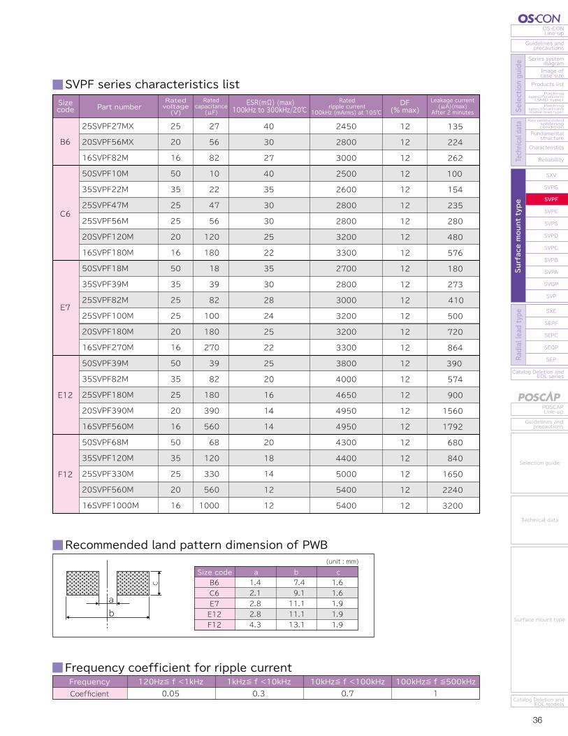
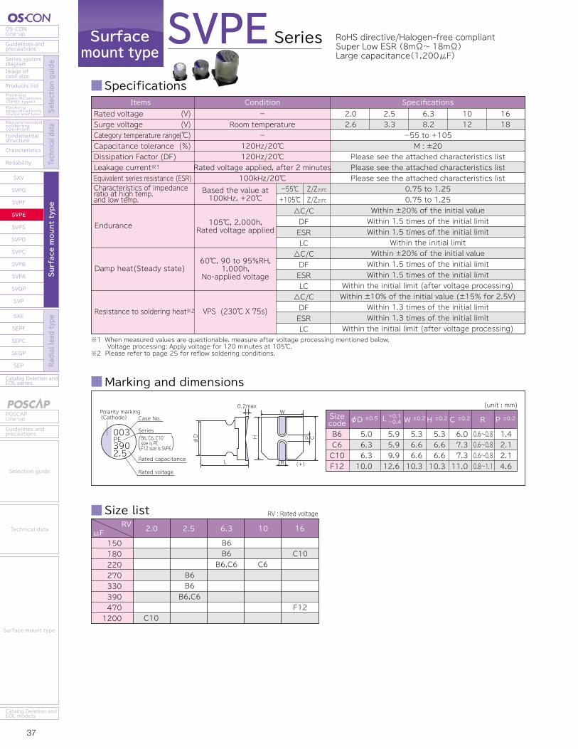
37 38
OS-CONLine-up
Guidelines andprecautions
Series systemdiagram
Recommendedsolderingcondition
Fundamentalstructure
Characteristics
Reliability
Catalog Deletion andEOL series
SXV
SVPG
SVPF
SVPE
SVPS
SVPD
SVPC
SVPB
SVPA
SVQP
SVP
SXE
SEPF
SEPC
SEQP
SEP
Image ofcase size
Products listPackingspecifications(SMD type)Packingspecifications(Radial lead type) Se
lection guide
Technical data
Surface mount type
Radial lead type
POSCAPLine-up
Guidelines andprecautions
Catalog Deletion andEOL models
Selection guide
Technical data
Surface mount type
Catalog Deletion andEOL series
SEP
SEQP
SEPC
SEPF
SXE
SXV
SVPG
SVPF
SVPE
SVPS
SVPD
SVPC
SVPB
SVPA
SVQP
SVP
Reliability
Characteristics
Fundamentalstructure
Recommendedsolderingcondition
Packingspecifications(Radial lead type)
Packingspecifications(SMD type)
Products list
Image ofcase size
Series systemdiagram
Guidelines andprecautions
OS-CONLine-up
Surface mount type
Radial lead type
Selection guide
Technical data
Guidelines andprecautions
POSCAPLine-up
Catalog Deletion andEOL models
Surface mount type
Technical data
Selection guide
Surfacemount type
Series
Specifications SVPE series characteristics list
SVPE RoHS directive/Halogen-free compliantSuper Low ESR (8mΩ~18mΩ)Large capacitance(1,200μF)
Frequency coefficient for ripple current
Recommended land pattern dimension of PWB
FrequencyCoefficient
120Hz≦ f <1kHz0.05
1kHz≦ f <10kHz0.3
10kHz≦ f <100kHz0.7
100kHz≦ f ≦500kHz1
Size codeB6C6C10F12
a b c1.42.12.14.3
7.49.19.113.1
1.61.61.61.9
(unit : mm)
C
ab
Sizecode
ESR(mΩ) (max)100kHz/20℃ 300kHz/20℃※1
Ratedripple current
100kHz (mArms) at 105℃ DF
(% max)Ratedvoltage(V)
Leakage current (μA)(max) After 2 minutes
6SVPE150M
6SVPE180M
6SVPE220MW
2R5SVPE270M
2R5SVPE330M
2R5SVPE330MY
2R5SVPE390MX
10SVPE220M
6SVPE220M
2R5SVPE390M
16SVPE180M
2SVPE1200M
16SVPE470M※1 The ESR value in 300kHz is a reference one.
Ratedcapacitance
(μF)Part number
C6
C10
F12
B6
6.3
6.3
6.3
2.5
2.5
2.5
2.5
10
6.3
2.5
16
2.0
16
150
180
220
270
330
330
390
220
220
390
180
1200
470
12
15
15
10
15
10
10
20
10
10
11
8
10
10
13
13
9
13
9
9
18
9
9
10
8
9
3520
3150
3150
3860
3150
3860
3860
2700
3900
3900
4460
5230
6100
12
12
12
12
12
12
12
12
12
12
12
12
12
500
500
500
500
500
500
700
500
500
500
576
500
1504
Marking and dimensions
(unit : mm)
φD ±0.5 W ±0.2 H ±0.2 C ±0.2 R P ±0.2Sizecode L +0.1-0.4
B6C6C10F12
5.06.36.310.0
5.95.99.912.6
5.36.66.610.3
5.36.66.610.3
6.07.37.311.0
0.6~0.80.6~0.80.6~0.80.8~1.1
1.42.12.14.6
φD
L
P
R
C
W0.2max
H
(+)
003PE3902.5
Case No.Polarity marking(Cathode)
Series
Rated capacitance
Rated voltage
B6, C6, C10size is PEF12 size is SVPE
Size list RV : Rated voltageRV
μF1501802202703303904701200
162.52.0 6.3 10
C10
F12
B6B6B6,C6 C6
B6B6B6,C6
C10
※1 When measured values are questionable, measure after voltage processing mentioned below. Voltage processing: Apply voltage for 120 minutes at 105℃. ※2 Please refer to page 25 for reflow soldering conditions.
Endurance
Characteristics of impedanceratio at high temp. and low temp.
Damp heat(Steady state)
Resistance to soldering heat※2
△C/CDFESRLC△C/CDFESRLC△C/CDFESRLC
-55℃+105℃
Z/Z20℃Z/Z20℃
-55 to +105M : ±20
Please see the attached characteristics listPlease see the attached characteristics listPlease see the attached characteristics list
2.02.6
2.53.3
6.38.2
1618
1012
SpecificationsItems
0.75 to 1.250.75 to 1.25
Within ±20% of the initial valueWithin 1.5 times of the initial limitWithin 1.5 times of the initial limit
Within the initial limitWithin ±20% of the initial valueWithin 1.5 times of the initial limitWithin 1.5 times of the initial limit
Within the initial limit (after voltage processing)Within ±10% of the initial value (±15% for 2.5V)
Within 1.3 times of the initial limitWithin 1.3 times of the initial limit
Within the initial limit (after voltage processing)
Rated voltageSurge voltageCategory temperature rangeCapacitance toleranceDissipation Factor (DF)Leakage current※1Equivalent series resistance (ESR)
(V)(V)(℃)(%)
105℃, 2,000h,Rated voltage applied
Based the value at100kHz, +20℃
60℃, 90 to 95%RH,1,000h,
No-applied voltage
VPS (230℃ X 75s)
Condition-
Room temperature-
120Hz/20℃120Hz/20℃
Rated voltage applied, after 2 minutes100kHz/20℃
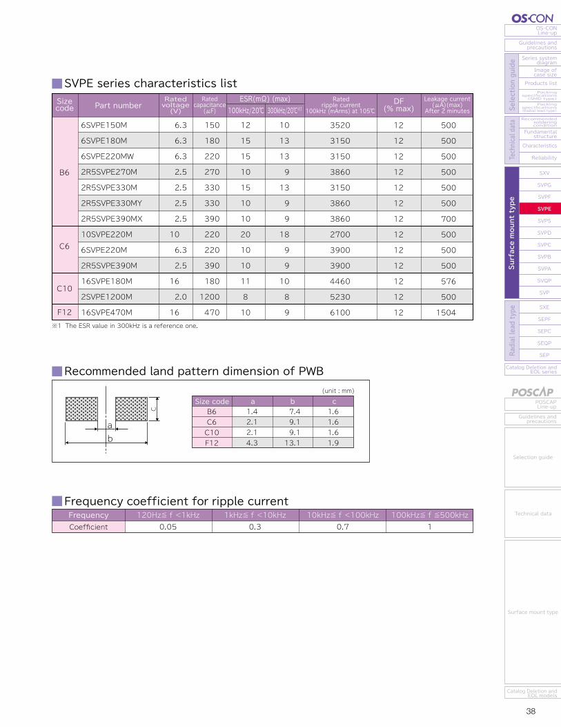

39 40
OS-CONLine-up
Guidelines andprecautions
Series systemdiagram
Recommendedsolderingcondition
Fundamentalstructure
Characteristics
Reliability
Catalog Deletion andEOL series
SXV
SVPG
SVPF
SVPE
SVPS
SVPD
SVPC
SVPB
SVPA
SVQP
SVP
SXE
SEPF
SEPC
SEQP
SEP
Image ofcase size
Products listPackingspecifications(SMD type)Packingspecifications(Radial lead type) Se
lection guide
Technical data
Surface mount type
Radial lead type
POSCAPLine-up
Guidelines andprecautions
Catalog Deletion andEOL models
Selection guide
Technical data
Surface mount type
Catalog Deletion andEOL series
SEP
SEQP
SEPC
SEPF
SXE
SXV
SVPG
SVPF
SVPE
SVPS
SVPD
SVPC
SVPB
SVPA
SVQP
SVP
Reliability
Characteristics
Fundamentalstructure
Recommendedsolderingcondition
Packingspecifications(Radial lead type)
Packingspecifications(SMD type)
Products list
Image ofcase size
Series systemdiagram
Guidelines andprecautions
OS-CONLine-up
Surface mount type
Radial lead type
Selection guide
Technical data
Guidelines andprecautions
POSCAPLine-up
Catalog Deletion andEOL models
Surface mount type
Technical data
Selection guide
Surfacemount type
Series
Specifications SVPS series characteristics list
SVPS RoHS directive/Halogen-free compliantEndurance: 105℃ 5,000h (Long life)
Frequency coefficient for ripple current
Recommended land pattern dimension of PWB
FrequencyCoefficient
120Hz≦ f <1kHz0.05
1kHz≦ f <10kHz0.3
10kHz≦ f <100kHz0.7
100kHz≦ f ≦500kHz1
Marking and dimensions
Size list RV : Rated voltage
Size codeA5B6C6E7F8
a b c1.01.42.12.84.3
6.27.49.111.113.1
1.61.61.61.91.9
(unit : mm)
C
ab
※1 The surface temperature of aluminum case top must not exceed 105℃. A rise in temperature due to self-heating by ripple current should be factored in.
A5
B6
C6
E7
F8
10SVPS10M10SVPS15M6SVPS22M4SVPS33M16SVPS22M10SVPS33M6SVPS47M4SVPS68M20SVPS22M16SVPS39M10SVPS68M6SVPS120M4SVPS150M25SVPS10M20SVPS47M16SVPS82M10SVPS150MX6SVPS220M4SVPS270M16SVPS100M16SVPS180M10SVPS150M10SVPS330M6SVPS470M4SVPS680M
1010
6.3 4.01610
6.3 4.0201610
6.3 4.025201610
6.3 4.016161010
6.3 4.0
10 15 22 33 22 33 47 68 22 39 68120150 10 47 82150220270100180150330470680
220200200200907030306024302222604530302222352930242020
700740740740106011001970197014502460220025702570150018902760276032203220267034303020377041304130
10101215101212121012121212101212121212121212121212
50 75 69.3 66176165300300 88300300300300125188262500500500320576300660592544
Sizecode
Allowableripple current
100kHz(mArms)※1DF
(% max)Ratedvoltage(V)
Leakage current (μA)(max) After 2 minutes
Part numberRated
capacitance(μF)
ESR(mΩ) (max)100kHz to 300kHz/20℃
RVμF 4.0 6.3 10 16
1015223339476882100120150180220270330470680
A5
B6
C6
E7
F8
A5A5
B6
C6
E7、F8
F8
B6
C6
E7F8
F8
20
C6
E7
25
E7
A5
B6
C6
E7
F8
φD ±0.5 W ±0.2 H ±0.2 C ±0.2 R P ±0.2L +0.1-0.4
A5B6C6E7F8
4.05.06.38.010.0
5.45.95.96.97.9
4.35.36.68.310.3
4.35.36.68.310.3
5.06.07.39.011.0
0.6~0.80.6~0.80.6~0.80.6~0.80.6~0.8
1.01.42.13.24.6
φD
L
P
R
C
W0.2max
H
(+)
003SVPS18016
Case No.Polarity marking(Cathode)
Series
Rated capacitanceRated voltage
B6,C6,E7,F8 size is SVPS※A5 is S on the side of rated capacitance
Sizecode
(unit : mm)
※1 When measured values are questionable, measure after voltage processing mentioned below. Voltage processing: Apply voltage for 120 minutes at 105℃. The voltage to be applied is the rated voltage for 4.0-20V products, and 20V for 25V products.※2 Please refer to page 25 for reflow soldering conditions.
Endurance
Characteristics of impedanceratio at high temp. and low temp.
Damp heat(Steady state)
Resistance to soldering heat※2
△C/CDFESRLC△C/CDFESRLC△C/CDFESRLC
-55℃+105℃
Z/Z20℃Z/Z20℃
-55 to +105M : ±20
Please see the attached characteristics listPlease see the attached characteristics listPlease see the attached characteristics list
4.05.2
6.38.2
1012
1618
2023
2525
SpecificationsItemsRated voltageSurge voltageCategory temperature rangeCapacitance toleranceDissipation Factor (DF)Leakage current※1
Equivalent series resistance (ESR)
(V)(V)(℃)(%)
105℃, 5,000h,Rated voltage applied (25V → 20V applied)
Based the value at100kHz, +20℃
60℃, 90 to 95% RH,1,000h,
No-applied voltage
VPS (230℃ X 75s)
Condition-
Room temperature-
120Hz/20℃120Hz/20℃
Rated voltage applied, after 2 minutes100kHz to 300kHz/20℃
0.75 to 1.250.75 to 1.25
Within ±20% of the initial valueWithin 1.5 times of the initial limitWithin 1.5 times of the initial limit
Within the initial limitWithin ±20% of the initial valueWithin 1.5 times of the initial limitWithin 1.5 times of the initial limit
Within the initial limit (after voltage processing)Within ±10% of the initial valueWithin 1.3 times of the initial limitWithin 1.3 times of the initial limit
Within the initial limit (after voltage processing)
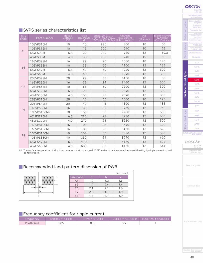
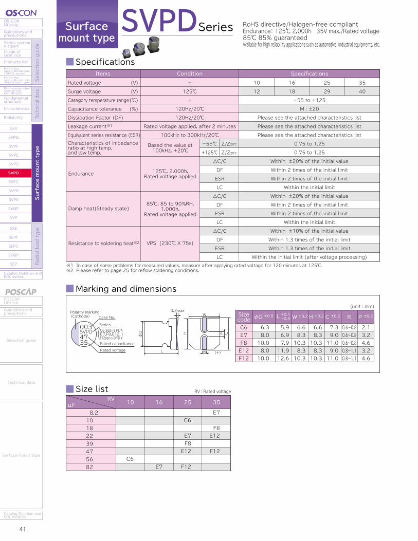
41 42
OS-CONLine-up
Guidelines andprecautions
Series systemdiagram
Recommendedsolderingcondition
Fundamentalstructure
Characteristics
Reliability
Catalog Deletion andEOL series
SXV
SVPG
SVPF
SVPE
SVPS
SVPD
SVPC
SVPB
SVPA
SVQP
SVP
SXE
SEPF
SEPC
SEQP
SEP
Image ofcase size
Products listPackingspecifications(SMD type)Packingspecifications(Radial lead type) Se
lection guide
Technical data
Surface mount type
Radial lead type
POSCAPLine-up
Guidelines andprecautions
Catalog Deletion andEOL models
Selection guide
Technical data
Surface mount type
Catalog Deletion andEOL series
SEP
SEQP
SEPC
SEPF
SXE
SXV
SVPG
SVPF
SVPE
SVPS
SVPD
SVPC
SVPB
SVPA
SVQP
SVP
Reliability
Characteristics
Fundamentalstructure
Recommendedsolderingcondition
Packingspecifications(Radial lead type)
Packingspecifications(SMD type)
Products list
Image ofcase size
Series systemdiagram
Guidelines andprecautions
OS-CONLine-up
Surface mount type
Radial lead type
Selection guide
Technical data
Guidelines andprecautions
POSCAPLine-up
Catalog Deletion andEOL models
Surface mount type
Technical data
Selection guide
Surfacemount type
Series
Specifications SVPD series characteristics list
SVPD RoHS directive/Halogen-free compliantEndurance: 125℃ 2,000h 35V max./Rated voltage85℃ 85% guaranteedAvailable for high reliability applications such as automotive, industrial equipments, etc.
Frequency coefficient for ripple current
Recommended land pattern dimension of PWB
FrequencyCoefficient
120Hz≦ f <1kHz0.05
1kHz≦ f <10kHz0.3
10kHz≦ f <100kHz0.7
100kHz≦ f ≦500kHz1
Marking and dimensions
Size list RV : Rated voltage
※1 In case of some problems for measured values, measure after applying rated voltage for 120 minutes at 125℃.※2 Please refer to page 25 for reflow soldering conditions.
Endurance
Characteristics of impedanceratio at high temp. and low temp.
Damp heat(Steady state)
Resistance to soldering heat※2
△C/CDFESRLC△C/CDFESRLC△C/CDFESRLC
-55℃
+125℃Z/Z20℃Z/Z20℃
-55 to +125M : ±20
Please see the attached characteristics listPlease see the attached characteristics listPlease see the attached characteristics list
1012
1618
2529
3540
SpecificationsItems
0.75 to 1.250.75 to 1.25
Within ±20% of the initial valueWithin 2 times of the initial limitWithin 2 times of the initial limit
Within the initial limitWithin ±20% of the initial valueWithin 2 times of the initial limitWithin 2 times of the initial limit
Within the initial limitWithin ±10% of the initial valueWithin 1.3 times of the initial limitWithin 1.3 times of the initial limit
Within the initial limit (after voltage processing)
Rated voltageSurge voltage
Category temperature rangeCapacitance toleranceDissipation Factor (DF)Leakage current※1
Equivalent series resistance (ESR)
(V)(V)(℃)(%)
125℃, 2,000h,Rated voltage applied
Based the value at100kHz, +20℃
85℃, 85 to 90%RH,1,000h,
Rated voltage applied
VPS (230℃ X 75s)
Condition-
125℃-
120Hz/20℃120Hz/20℃
Rated voltage applied, after 2 minutes100kHz to 300kHz/20℃
RVμF 10 16 25 35
8.210 18 22 39 47 56 82 E7
C6
E7F8E12
F12
E7
F8E12
F12C6
(unit : mm)
φD ±0.5 W ±0.2 H ±0.2 C ±0.2 R P ±0.2Sizecode L +0.1-0.4
C6E7F8E12F12
6.38.010.08.010.0
5.96.97.911.912.6
6.68.310.38.310.3
6.68.310.38.310.3
7.39.011.09.011.0
0.6~0.80.6~0.80.6~0.80.8~1.10.8~1.1
2.13.24.63.24.6
φD
L
P
R
C
W0.2max
H
(+)
003SVPD4735
Case No.Polarity marking(Cathode)
Series
Rated capacitanceRated voltage
C6 size is PDE7,F8,E12,F12size is SVPD
※1 Tx : Ambient temperature
E7
F8
E12
F12
C625SVPD10M
10SVPD56M
35SVPD8R2M
25SVPD22M
16SVPD82M
35SVPD18M
25SVPD39M
35SVPD22M
25SVPD47M
35SVPD47M
25SVPD82M
25
10
35
25
16
35
25
35
25
35
25
10
56
8.2
22
82
18
39
22
47
47
82
65
45
70
48
40
60
45
50
30
30
28
474
538
400
580
670
550
664
700
943
1150
1202
1500
1700
1300
1835
2120
1800
2100
2300
2980
3650
3800
10
12
10
10
12
10
10
12
12
12
12
50
112
57
110
262
126
195
154
235
329
410
Sizecode
ESR(mΩ) (max)100kHz to 300kHz/20℃
Rated ripple current100kHz(mArms)
Allowable ripple current
105℃<Tx≦125℃※1 Tx≦105℃※1DF
(% max)Ratedvoltage(V)
Leakage current (μA)(max) After 2 minutes
Ratedcapacitance
(μF)Part number
Size codeC6E7F8E12F12
a b c2.12.84.32.84.3
9.111.113.111.113.1
1.61.91.91.91.9
(unit : mm)
C
ab
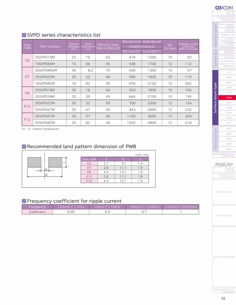
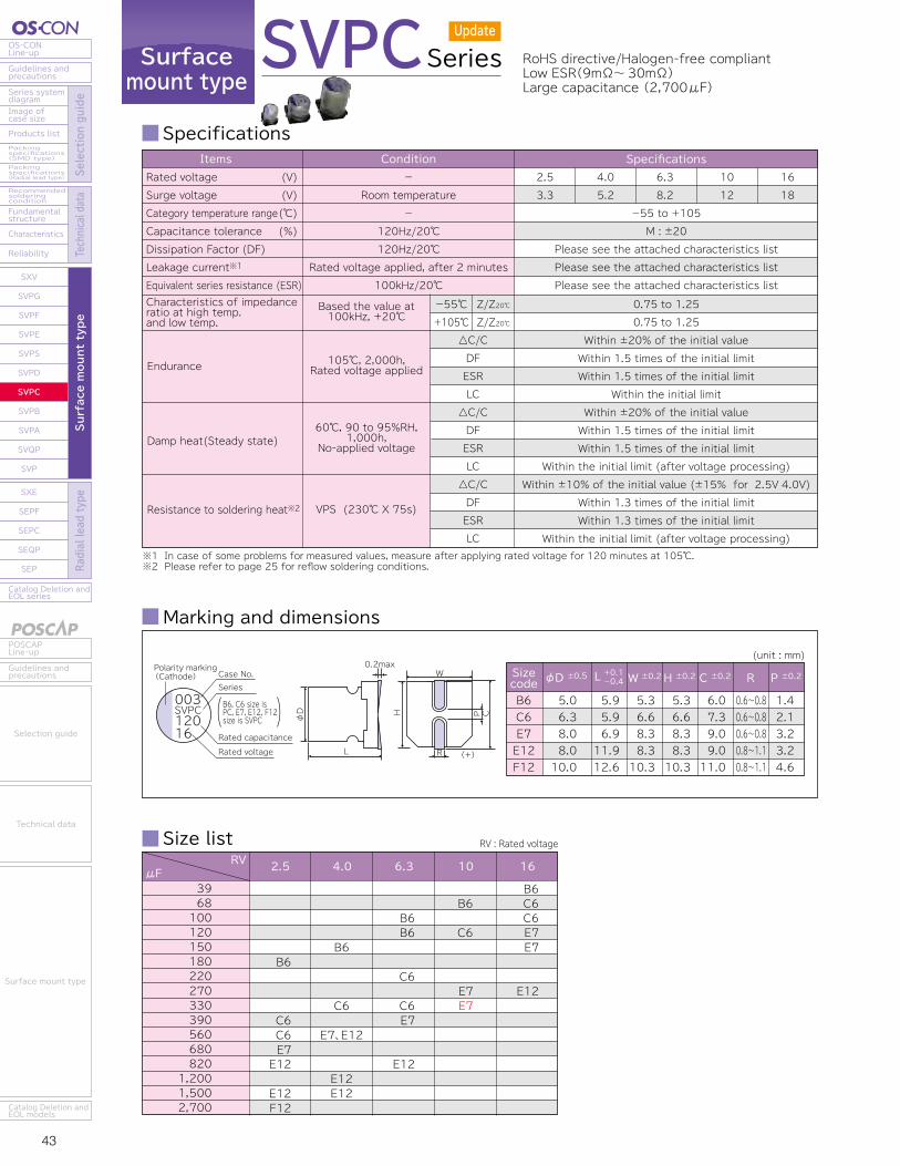
43 44
OS-CONLine-up
Guidelines andprecautions
Series systemdiagram
Recommendedsolderingcondition
Fundamentalstructure
Characteristics
Reliability
Catalog Deletion andEOL series
SXV
SVPG
SVPF
SVPE
SVPS
SVPD
SVPC
SVPB
SVPA
SVQP
SVP
SXE
SEPF
SEPC
SEQP
SEP
Image ofcase size
Products listPackingspecifications(SMD type)Packingspecifications(Radial lead type) Se
lection guide
Technical data
Surface mount type
Radial lead type
POSCAPLine-up
Guidelines andprecautions
Catalog Deletion andEOL models
Selection guide
Technical data
Surface mount type
Catalog Deletion andEOL series
SEP
SEQP
SEPC
SEPF
SXE
SXV
SVPG
SVPF
SVPE
SVPS
SVPD
SVPC
SVPB
SVPA
SVQP
SVP
Reliability
Characteristics
Fundamentalstructure
Recommendedsolderingcondition
Packingspecifications(Radial lead type)
Packingspecifications(SMD type)
Products list
Image ofcase size
Series systemdiagram
Guidelines andprecautions
OS-CONLine-up
Surface mount type
Radial lead type
Selection guide
Technical data
Guidelines andprecautions
POSCAPLine-up
Catalog Deletion andEOL models
Surface mount type
Technical data
Selection guide
Surfacemount type
Series
Specifications
SVPC series characteristics listSVPC RoHS directive/Halogen-free compliant
Low ESR(9mΩ~30mΩ)Large capacitance (2,700μF)
Frequency coefficient for ripple current
Recommended land pattern dimension of PWB
FrequencyCoefficient
120Hz≦ f <1kHz0.05
1kHz≦ f <10kHz0.3
10kHz≦ f <100kHz0.7
100kHz≦ f ≦500kHz1
Marking and dimensions
Size list RV : Rated voltage
※1 In case of some problems for measured values, measure after applying rated voltage for 120 minutes at 105℃.※2 Please refer to page 25 for reflow soldering conditions.
Endurance
Characteristics of impedanceratio at high temp. and low temp.
Damp heat(Steady state)
Resistance to soldering heat※2
△C/CDFESRLC△C/CDFESRLC△C/CDFESRLC
-55℃+105℃
Z/Z20℃Z/Z20℃
-55 to +105M : ±20
Please see the attached characteristics listPlease see the attached characteristics listPlease see the attached characteristics list
2.53.3
4.05.2
6.38.2
1012
1618
SpecificationsItemsRated voltageSurge voltageCategory temperature rangeCapacitance toleranceDissipation Factor (DF)Leakage current※1
Equivalent series resistance (ESR)
(V)(V)(℃)(%)
105℃, 2,000h,Rated voltage applied
Based the value at100kHz, +20℃
60℃, 90 to 95%RH,1,000h,
No-applied voltage
VPS (230℃ X 75s)
Condition-
Room temperature-
120Hz/20℃120Hz/20℃
Rated voltage applied, after 2 minutes100kHz/20℃
0.75 to 1.250.75 to 1.25
Within ±20% of the initial valueWithin 1.5 times of the initial limitWithin 1.5 times of the initial limit
Within the initial limitWithin ±20% of the initial valueWithin 1.5 times of the initial limitWithin 1.5 times of the initial limit
Within the initial limit (after voltage processing)Within ±10% of the initial value (±15% for 2.5V 4.0V)
Within 1.3 times of the initial limitWithin 1.3 times of the initial limit
Within the initial limit (after voltage processing)
RVμF 2.5 4.0 6.3 10 16
3968100120150180220270330390560680820
1,2001,5002,700
B6
C6C6E7E12
E12F12
B6
C6
E7、E12
E12E12
B6B6
C6
C6E7
E12
B6
C6
E7E7
B6C6C6E7E7
E12
(unit : mm)
φD ±0.5 W ±0.2 H ±0.2 C ±0.2 R P ±0.2Sizecode L +0.1-0.4
φD
L
P
R
C
W0.2max
H
(+)
003SVPC12016
Case No.Polarity marking(Cathode)
Series
B6, C6 size is PC, E7, E12, F12 size is SVPC
Rated capacitanceRated voltage
B6C6E7E12F12
5.06.38.08.010.0
5.95.96.911.912.6
5.36.68.38.310.3
5.36.68.38.310.3
6.07.39.09.011.0
0.6~0.80.6~0.80.6~0.80.8~1.10.8~1.1
1.42.13.23.24.6
※ Red letters : New models
Size code a b c(unit : mm)
B6C6E7E12F12
1.42.12.82.84.3
7.49.111.111.113.1
1.61.61.91.91.9
C
ab
B6
Sizecode
ESR (mΩ) (max) 100kHz/20℃ 300kHz/20℃※1
C6
E7
E12
F12
Ratedripple current100kHz (mArms) at 105℃
DF(% max)
Ratedvoltage(V)
Leakage current (μA)(max) After 2 minutes
16SVPC39M16SVPC39MV10SVPC68M10SVPC68MV6SVPC100M6SVPC100MY6SVPC120MV4SVPC150M4SVPC150MY4SVPC150MV2R5SVPC180M2R5SVPC180MY2R5SVPC180MV16SVPC68M16SVPC68MV16SVPC100M10SVPC120M10SVPC120MV6SVPC220M6SVPC220MV6SVPC330M4SVPC330M4SVPC330MY4SVPC330MV2R5SVPC390M2R5SVPC390MV2R5SVPC560M16SVPC120M16SVPC150M10SVPC270M10SVPC330M6SVPC390M4SVPC560M2R5SVPC680M16SVPC270M6SVPC820M4SVPC560MX4SVPC1200M4SVPC1500M2R5SVPC820M2R5SVPC1500M2R5SVPC2700M
16 16 10 10 6.36.36.34.04.04.02.52.52.516 16 16 10 10 6.36.36.34.04.04.02.52.52.516 16 10 10 6.34.02.516 6.34.04.04.02.52.52.5
39396868100 100120150 150150180 180180 68 68100120120220 220330 330 330 330390390560120150270330390 560 6802708205601200150082015002700
352730233025213023203024193025242722271517272115251516272222192222201612 91212 91012
302326202621182620172620162622232319231315231813221314232119171919171410 81010 8 910
182023501970254019702150266019702240273019702200280022002440249023202600232031603390232026303160241031603500290032203220346032203220337040704700538047004700538051505070
121212121212121212121212121212121212121212121212121212121212121212121515151515151515
3003003003003003003003003003003003003003003003003003003003004153003003003003003005005005006604915005008641033 5009601200 5007501350
※1 The ESR value in 300kHz is a reference one.
Ratedcapacitance
(μF)Part number
Update
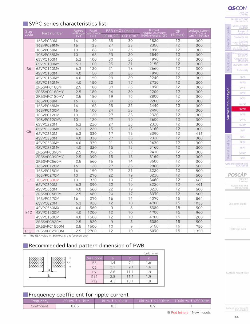
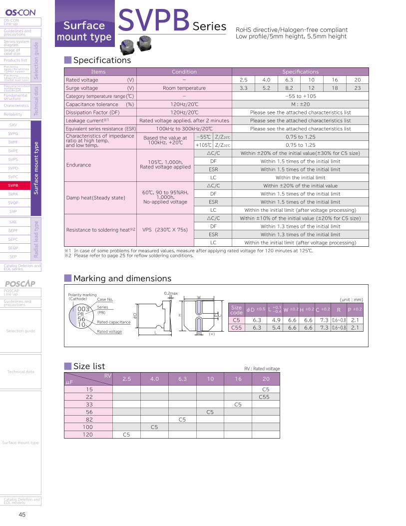
45 46
OS-CONLine-up
Guidelines andprecautions
Series systemdiagram
Recommendedsolderingcondition
Fundamentalstructure
Characteristics
Reliability
Catalog Deletion andEOL series
SXV
SVPG
SVPF
SVPE
SVPS
SVPD
SVPC
SVPB
SVPA
SVQP
SVP
SXE
SEPF
SEPC
SEQP
SEP
Image ofcase size
Products listPackingspecifications(SMD type)Packingspecifications(Radial lead type) Se
lection guide
Technical data
Surface mount type
Radial lead type
POSCAPLine-up
Guidelines andprecautions
Catalog Deletion andEOL models
Selection guide
Technical data
Surface mount type
Catalog Deletion andEOL series
SEP
SEQP
SEPC
SEPF
SXE
SXV
SVPG
SVPF
SVPE
SVPS
SVPD
SVPC
SVPB
SVPA
SVQP
SVP
Reliability
Characteristics
Fundamentalstructure
Recommendedsolderingcondition
Packingspecifications(Radial lead type)
Packingspecifications(SMD type)
Products list
Image ofcase size
Series systemdiagram
Guidelines andprecautions
OS-CONLine-up
Surface mount type
Radial lead type
Selection guide
Technical data
Guidelines andprecautions
POSCAPLine-up
Catalog Deletion andEOL models
Surface mount type
Technical data
Selection guide
Surfacemount type
Series
Specifications SVPB series characteristics list
SVPB RoHS directive/Halogen-free compliantLow profile/5mm height, 5.5mm height
Frequency coefficient for ripple current
Recommended land pattern dimension of PWB
FrequencyCoefficient
120Hz≦ f <1kHz0.05
1kHz≦ f <10kHz0.3
10kHz≦ f <100kHz0.7
100kHz≦ f ≦500kHz1
Marking and dimensions
Size list RV : Rated voltage
※1 In case of some problems for measured values, measure after applying rated voltage for 120 minutes at 125℃.※2 Please refer to page 25 for reflow soldering conditions.
Endurance
Characteristics of impedanceratio at high temp. and low temp.
Damp heat(Steady state)
Resistance to soldering heat※2
△C/CDFESRLC△C/CDFESRLC△C/CDFESRLC
-55℃+105℃
Z/Z20℃Z/Z20℃
-55 to +105M : ±20
Please see the attached characteristics listPlease see the attached characteristics listPlease see the attached characteristics list
2.53.3
4.05.2
6.38.2
1012
1618
2023
SpecificationsItemsRated voltageSurge voltageCategory temperature rangeCapacitance toleranceDissipation Factor (DF)Leakage current※1
Equivalent series resistance (ESR)
(V)(V)(℃)(%)
105℃, 1,000h,Rated voltage applied
Based the value at100kHz, +20℃
60℃, 90 to 95%RH,1,000h,
No-applied voltage
VPS (230℃ X 75s)
Condition-
Room temperature-
120Hz/20℃120Hz/20℃
Rated voltage applied, after 2 minutes100kHz to 300kHz/20℃
0.75 to 1.250.75 to 1.25
Within ±20% of the initial value(±30% for C5 size)Within 1.5 times of the initial limitWithin 1.5 times of the initial limit
Within the initial limitWithin ±20% of the initial valueWithin 1.5 times of the initial limitWithin 1.5 times of the initial limit
Within the initial limit (after voltage processing)Within ±10% of the initial value (±20% for C5 size)
Within 1.3 times of the initial limitWithin 1.3 times of the initial limit
Within the initial limit (after voltage processing)
RVμF
1522335682100120 C5
2.5
C5
4.0
C5
6.3
C5
10
C5
16
C5C55
20
(unit : mm)
φD ±0.5 W ±0.2 H ±0.2 C ±0.2 R P ±0.2Sizecode L +0.1-0.4
C5C55
6.36.3
4.95.4
6.66.6
6.66.6
7.37.3
0.6~0.80.6~0.8
2.12.1
φD
L
P
R
C
W0.2max
H
(+)
003PB5610
Case No.Polarity marking(Cathode)
Series (PB)
Rated capacitance
Rated voltage
Size codeC5C55
a b c2.12.1
9.19.1
1.61.6
(unit : mm)
C
ab
C55
C5
20SVPB15M
16SVPB33M
10SVPB56M
6SVPB82M
4SVPB100M
2R5SVPB120M
20SVPB22M
20
16
10
6.3
4.0
2.5
20
15
33
56
82
100
120
22
45
40
40
40
40
40
35
2000
1670
1670
1670
1670
1670
2000
12
12
12
12
12
12
12
120
211
224
207
160
120
88
Sizecode
Ratedripple current100kHz (mArms) at 105℃
DF(% max)
Ratedvoltage(V)
Leakage current (μA)(max) After 2 minutes
ESR (mΩ) (max)100kHz to 300kHz/20℃
Ratedcapacitance
(μF)Part number

47 48
OS-CONLine-up
Guidelines andprecautions
Series systemdiagram
Recommendedsolderingcondition
Fundamentalstructure
Characteristics
Reliability
Catalog Deletion andEOL series
SXV
SVPG
SVPF
SVPE
SVPS
SVPD
SVPC
SVPB
SVPA
SVQP
SVP
SXE
SEPF
SEPC
SEQP
SEP
Image ofcase size
Products listPackingspecifications(SMD type)Packingspecifications(Radial lead type) Se
lection guide
Technical data
Surface mount type
Radial lead type
POSCAPLine-up
Guidelines andprecautions
Catalog Deletion andEOL models
Selection guide
Technical data
Surface mount type
Catalog Deletion andEOL series
SEP
SEQP
SEPC
SEPF
SXE
SXV
SVPG
SVPF
SVPE
SVPS
SVPD
SVPC
SVPB
SVPA
SVQP
SVP
Reliability
Characteristics
Fundamentalstructure
Recommendedsolderingcondition
Packingspecifications(Radial lead type)
Packingspecifications(SMD type)
Products list
Image ofcase size
Series systemdiagram
Guidelines andprecautions
OS-CONLine-up
Surface mount type
Radial lead type
Selection guide
Technical data
Guidelines andprecautions
POSCAPLine-up
Catalog Deletion andEOL models
Surface mount type
Technical data
Selection guide
Surfacemount type
Series
Specifications SVPA series characteristics list
SVPA RoHS directive/Halogen-free compliantLow ESR 18mΩHigh rated ripple current (4,240mArms)
Frequency coefficient for ripple currentFrequencyCoefficient
120Hz≦ f <1kHz0.05
1kHz≦ f <10kHz0.3
10kHz≦ f <100kHz0.7
100kHz≦ f ≦500kHz1
Marking and dimensions
Size list RV : Rated voltage
※1 In case of some problems for measured values, measure after applying rated voltage for 120 minutes at 105℃.※2 Please refer to page 25 for reflow soldering conditions.
Endurance
Characteristics of impedanceratio at high temp. and low temp.
Damp heat(Steady state)
Resistance to soldering heat※2
△C/CDFESRLC△C/CDFESRLC△C/CDFESRLC
-55℃+105℃
Z/Z20℃Z/Z20℃
-55 to +105M : ±20
Please see the attached characteristics listPlease see the attached characteristics listPlease see the attached characteristics list
2.53.3
4.05.2
6.38.2
1012
1618
2023
SpecificationsItemsRated voltageSurge voltageCategory temperature rangeCapacitance toleranceDissipation Factor (DF)Leakage current※1
Equivalent series resistance (ESR)
(V)(V)(℃)(%)
105℃, 2,000h,Rated voltage applied
Based the value at100kHz, +20℃
60℃, 90 to 95%RH,1,000h,
No-applied voltage
VPS (230℃ X 75s)
Condition-
Room temperature-
120Hz/20℃120Hz/20℃
Rated voltage applied, after 2 minutes100kHz/20℃
0.75 to 1.250.75 to 1.25
Within ±20% of the initial valueWithin 1.5 times of the initial limitWithin 1.5 times of the initial limit
Within the initial limitWithin ±20% of the initial valueWithin 1.5 times of the initial limitWithin 1.5 times of the initial limit
Within the initial limit (after voltage processing)Within ±10% of the initial valueWithin 1.3 times of the initial limitWithin 1.3 times of the initial limit
Within the initial limit (after voltage processing)
(unit : mm)
φD ±0.5 W ±0.2 H ±0.2 C ±0.2 R P ±0.2Sizecode L +0.1-0.4
B6C6E7F8
5.06.38.010.0
5.95.96.97.9
5.36.68.310.3
5.36.68.310.3
6.07.39.011.0
0.6~0.80.6~0.80.6~0.80.6~0.8
1.42.13.24.6
φD
L
P
R
C
W0.2max
H
(+)
003SVPA4720
Case No.Polarity marking(Cathode)
Series
Rated capacitance
Rated voltage
B6, C6 size is PA, E7, F8 size is
RVμF 2.5 4.0 6.3 10 16
102239476882120150180220270330470680820
B6
C6
E7
F8
B6
C6
E7
F8
B6
C6
E7
F8
C6
E7
F8
C6
E7
F8
20
B6C6
E7
Recommended land pattern dimension of PWB
Size codeB6C6E7F8
a b c1.42.12.84.3
7.49.111.113.1
1.61.61.91.9
(unit : mm)
C
ab
※1 The ESR value at 300kHz is a reference one.
B6
20SVPA10M
6SVPA47MAA
4SVPA68MAA
2R5SVPA82MAA
20SVPA22M
16SVPA39MAA
16SVPA39MAAY
10SVPA68MAA
6SVPA120MAA
4SVPA150MAA
2R5SVPA180MAA
20SVPA47M
16SVPA82MAA
10SVPA150MAA
6SVPA220MAA
4SVPA270MAA
2R5SVPA330MAA
16SVPA180M
10SVPA330M
6SVPA470M
4SVPA680M
2R5SVPA820M
20
6.3
4.0
2.5
20
16
16
10
6.3
4.0
2.5
20
16
10
6.3
4.0
2.5
16
10
6.3
4.0
2.5
10
47
68
82
22
39
39
68
120
150
180
47
82
150
220
270
330
180
330
470
680
820
40
30
30
30
35
35
24
30
22
22
20
33
30
30
22
22
20
29
24
20
20
19
35
26
26
26
31
31
20
26
19
19
18
29
25
25
19
19
18
28
23
19
19
18
1700
1970
1970
1970
2040
2040
2460
2200
2570
2570
2690
2630
2760
2760
3220
3220
3370
3430
3770
4130
4130
4240
12
12
12
12
12
12
12
12
12
12
12
12
12
12
12
12
12
12
12
12
12
12
80
300
300
300
88
300
300
300
300
300
300
188
262
500
500
500
500
576
660
592
544
500
Sizecode
ESR (mΩ) (max)100kHz/20℃ 300kHz/20℃※1
C6
E7
F8
Ratedripple current
100kHz (mArms) at 105℃DF
(% max)Ratedvoltage(V)
Ratedcapacitance
(μF)
Leakage current (μA)(max) After 2 minutes
Part number
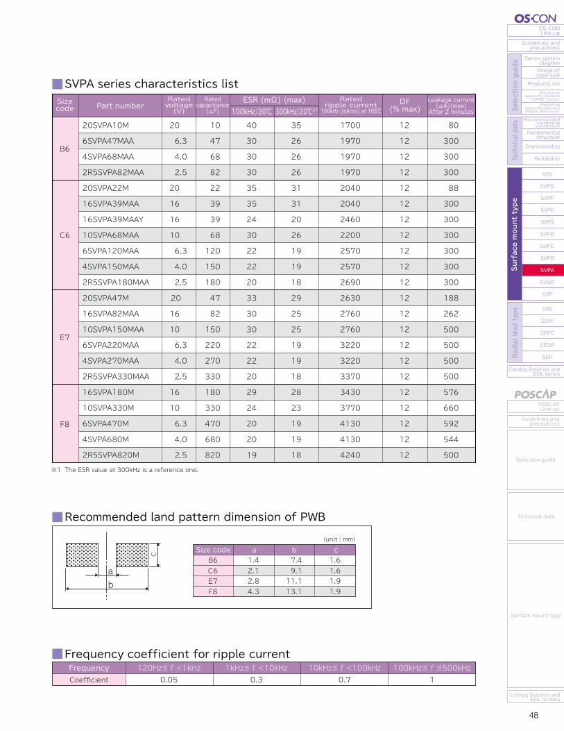
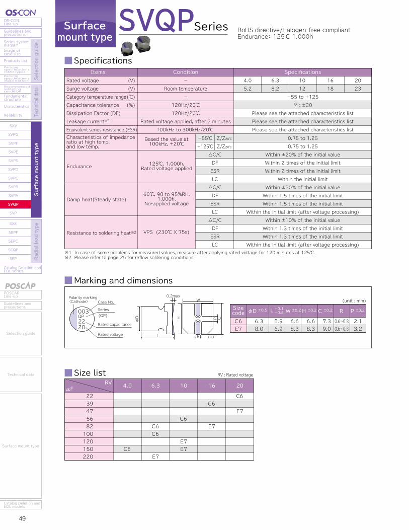
49 50
OS-CONLine-up
Guidelines andprecautions
Series systemdiagram
Recommendedsolderingcondition
Fundamentalstructure
Characteristics
Reliability
Catalog Deletion andEOL series
SXV
SVPG
SVPF
SVPE
SVPS
SVPD
SVPC
SVPB
SVPA
SVQP
SVP
SXE
SEPF
SEPC
SEQP
SEP
Image ofcase size
Products listPackingspecifications(SMD type)Packingspecifications(Radial lead type) Se
lection guide
Technical data
Surface mount type
Radial lead type
POSCAPLine-up
Guidelines andprecautions
Catalog Deletion andEOL models
Selection guide
Technical data
Surface mount type
Catalog Deletion andEOL series
SEP
SEQP
SEPC
SEPF
SXE
SXV
SVPG
SVPF
SVPE
SVPS
SVPD
SVPC
SVPB
SVPA
SVQP
SVP
Reliability
Characteristics
Fundamentalstructure
Recommendedsolderingcondition
Packingspecifications(Radial lead type)
Packingspecifications(SMD type)
Products list
Image ofcase size
Series systemdiagram
Guidelines andprecautions
OS-CONLine-up
Surface mount type
Radial lead type
Selection guide
Technical data
Guidelines andprecautions
POSCAPLine-up
Catalog Deletion andEOL models
Surface mount type
Technical data
Selection guide
Surfacemount type
Series
Specifications SVQP series characteristics list
SVQP RoHS directive/Halogen-free compliantEndurance: 125℃ 1,000h
Frequency coefficient for ripple currentFrequencyCoefficient
120Hz≦ f <1kHz0.05
1kHz≦ f <10kHz0.3
10kHz≦ f <100kHz0.7
100kHz≦ f ≦500kHz1
Marking and dimensions
Size list RV : Rated voltage
Recommended land pattern dimension of PWB
(unit : mm)
φD ±0.5 W ±0.2 H ±0.2 C ±0.2 R P ±0.2Sizecode L +0.1-0.4
C6E7
6.38.0
5.96.9
6.68.3
6.68.3
7.39.0
0.6~0.80.6~0.8
2.13.2
φD
L
P
R
C
W0.2max
H
(+)
003QP2220
Case No.Polarity marking(Cathode)
Series (QP)
Rated capacitance
Rated voltage
RVμF 4.0 6.3 10 16 20
2239475682100120150220
C6
C6C6
E7
C6
E7E7
C6
E7
C6
E7
※1 In case of some problems for measured values, measure after applying rated voltage for 120 minutes at 125℃.※2 Please refer to page 25 for reflow soldering conditions.
Endurance
Characteristics of impedanceratio at high temp. and low temp.
Damp heat(Steady state)
Resistance to soldering heat※2
△C/CDFESRLC△C/CDFESRLC△C/CDFESRLC
-55℃+125℃
Z/Z20℃Z/Z20℃
-55 to +125M : ±20
Please see the attached characteristics listPlease see the attached characteristics listPlease see the attached characteristics list
4.05.2
6.38.2
1012
1618
2023
SpecificationsItemsRated voltageSurge voltageCategory temperature rangeCapacitance toleranceDissipation Factor (DF)Leakage current※1
Equivalent series resistance (ESR)
(V)(V)(℃)(%)
125℃, 1,000h,Rated voltage applied
Based the value at100kHz, +20℃
60℃, 90 to 95%RH,1,000h,
No-applied voltage
VPS (230℃ X 75s)
Condition-
Room temperature-
120Hz/20℃120Hz/20℃
Rated voltage applied, after 2 minutes100kHz to 300kHz/20℃
0.75 to 1.250.75 to 1.25
Within ±20% of the initial valueWithin 2 times of the initial limitWithin 2 times of the initial limit
Within the initial limitWithin ±20% of the initial valueWithin 1.5 times of the initial limitWithin 1.5 times of the initial limit
Within the initial limit (after voltage processing)Within ±10% of the initial valueWithin 1.3 times of the initial limitWithin 1.3 times of the initial limit
Within the initial limit (after voltage processing)
Size codeC6E7
a b c2.12.8
9.111.1
1.61.9
(unit : mm)
C
ab
※1 Tx : Ambient temperature
C6
E7
20SVQP22M
16SVQP39M
10SVQP56M
6SVQP82M
6SVQP100M
4SVQP150M
20SVQP47M
16SVQP82M
10SVQP120M
10SVQP150M
6SVQP220M
20
16
10
6.3
6.3
4.0
20
16
10
10
6.3
22
39
56
82
100
150
47
82
120
150
220
60
50
45
45
40
40
45
40
35
35
35
459
512
538
538
572
572
598
670
810
810
810
1450
1620
1700
1700
1810
1810
1890
2120
2560
2560
2560
10
10
12
12
12
12
12
12
12
12
12
220
312
280
258
315
300
470
656
600
750
693
Sizecode
ESR(mΩ) (max)100kHz to 300kHz/20℃
Rated ripple current100kHz(mArms)
Allowable ripple current
105℃<Tx≦125℃※1 Tx≦105℃※1
DF(% max)
Ratedvoltage(V)
Ratedcapacitance
(μF)
Leakage current (μA)(max) After 2 minutes
Part number
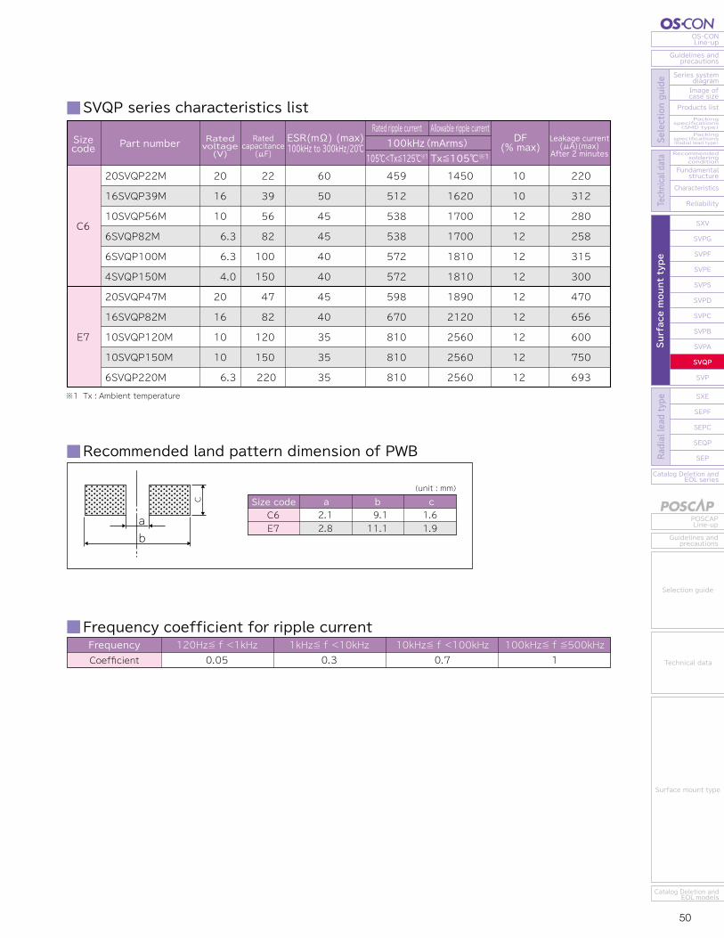
49 50
OS-CONLine-up
Guidelines andprecautions
Series systemdiagram
Recommendedsolderingcondition
Fundamentalstructure
Characteristics
Reliability
Catalog Deletion andEOL series
SXV
SVPG
SVPF
SVPE
SVPS
SVPD
SVPC
SVPB
SVPA
SVQP
SVP
SXE
SEPF
SEPC
SEQP
SEP
Image ofcase size
Products listPackingspecifications(SMD type)Packingspecifications(Radial lead type) Se
lection guide
Technical data
Surface mount type
Radial lead type
POSCAPLine-up
Guidelines andprecautions
Catalog Deletion andEOL models
Selection guide
Technical data
Surface mount type
Catalog Deletion andEOL series
SEP
SEQP
SEPC
SEPF
SXE
SXV
SVPG
SVPF
SVPE
SVPS
SVPD
SVPC
SVPB
SVPA
SVQP
SVP
Reliability
Characteristics
Fundamentalstructure
Recommendedsolderingcondition
Packingspecifications(Radial lead type)
Packingspecifications(SMD type)
Products list
Image ofcase size
Series systemdiagram
Guidelines andprecautions
OS-CONLine-up
Surface mount type
Radial lead type
Selection guide
Technical data
Guidelines andprecautions
POSCAPLine-up
Catalog Deletion andEOL models
Surface mount type
Technical data
Selection guide
Surfacemount type
Series
Specifications SVQP series characteristics list
SVQP RoHS directive/Halogen-free compliantEndurance: 125℃ 1,000h
Frequency coefficient for ripple currentFrequencyCoefficient
120Hz≦ f <1kHz0.05
1kHz≦ f <10kHz0.3
10kHz≦ f <100kHz0.7
100kHz≦ f ≦500kHz1
Marking and dimensions
Size list RV : Rated voltage
Recommended land pattern dimension of PWB
(unit : mm)
φD ±0.5 W ±0.2 H ±0.2 C ±0.2 R P ±0.2Sizecode L +0.1-0.4
C6E7
6.38.0
5.96.9
6.68.3
6.68.3
7.39.0
0.6~0.80.6~0.8
2.13.2
φD
L
P
R
C
W0.2max
H
(+)
003QP2220
Case No.Polarity marking(Cathode)
Series (QP)
Rated capacitance
Rated voltage
RVμF 4.0 6.3 10 16 20
2239475682100120150220
C6
C6C6
E7
C6
E7E7
C6
E7
C6
E7
※1 In case of some problems for measured values, measure after applying rated voltage for 120 minutes at 125℃.※2 Please refer to page 25 for reflow soldering conditions.
Endurance
Characteristics of impedanceratio at high temp. and low temp.
Damp heat(Steady state)
Resistance to soldering heat※2
△C/CDFESRLC△C/CDFESRLC△C/CDFESRLC
-55℃+125℃
Z/Z20℃Z/Z20℃
-55 to +125M : ±20
Please see the attached characteristics listPlease see the attached characteristics listPlease see the attached characteristics list
4.05.2
6.38.2
1012
1618
2023
SpecificationsItemsRated voltageSurge voltageCategory temperature rangeCapacitance toleranceDissipation Factor (DF)Leakage current※1
Equivalent series resistance (ESR)
(V)(V)(℃)(%)
125℃, 1,000h,Rated voltage applied
Based the value at100kHz, +20℃
60℃, 90 to 95%RH,1,000h,
No-applied voltage
VPS (230℃ X 75s)
Condition-
Room temperature-
120Hz/20℃120Hz/20℃
Rated voltage applied, after 2 minutes100kHz to 300kHz/20℃
0.75 to 1.250.75 to 1.25
Within ±20% of the initial valueWithin 2 times of the initial limitWithin 2 times of the initial limit
Within the initial limitWithin ±20% of the initial valueWithin 1.5 times of the initial limitWithin 1.5 times of the initial limit
Within the initial limit (after voltage processing)Within ±10% of the initial valueWithin 1.3 times of the initial limitWithin 1.3 times of the initial limit
Within the initial limit (after voltage processing)
Size codeC6E7
a b c2.12.8
9.111.1
1.61.9
(unit : mm)
C
ab
※1 Tx : Ambient temperature
C6
E7
20SVQP22M
16SVQP39M
10SVQP56M
6SVQP82M
6SVQP100M
4SVQP150M
20SVQP47M
16SVQP82M
10SVQP120M
10SVQP150M
6SVQP220M
20
16
10
6.3
6.3
4.0
20
16
10
10
6.3
22
39
56
82
100
150
47
82
120
150
220
60
50
45
45
40
40
45
40
35
35
35
459
512
538
538
572
572
598
670
810
810
810
1450
1620
1700
1700
1810
1810
1890
2120
2560
2560
2560
10
10
12
12
12
12
12
12
12
12
12
220
312
280
258
315
300
470
656
600
750
693
Sizecode
ESR(mΩ) (max)100kHz to 300kHz/20℃
Rated ripple current100kHz(mArms)
Allowable ripple current
105℃<Tx≦125℃※1 Tx≦105℃※1
DF(% max)
Ratedvoltage(V)
Ratedcapacitance
(μF)
Leakage current (μA)(max) After 2 minutes
Part number
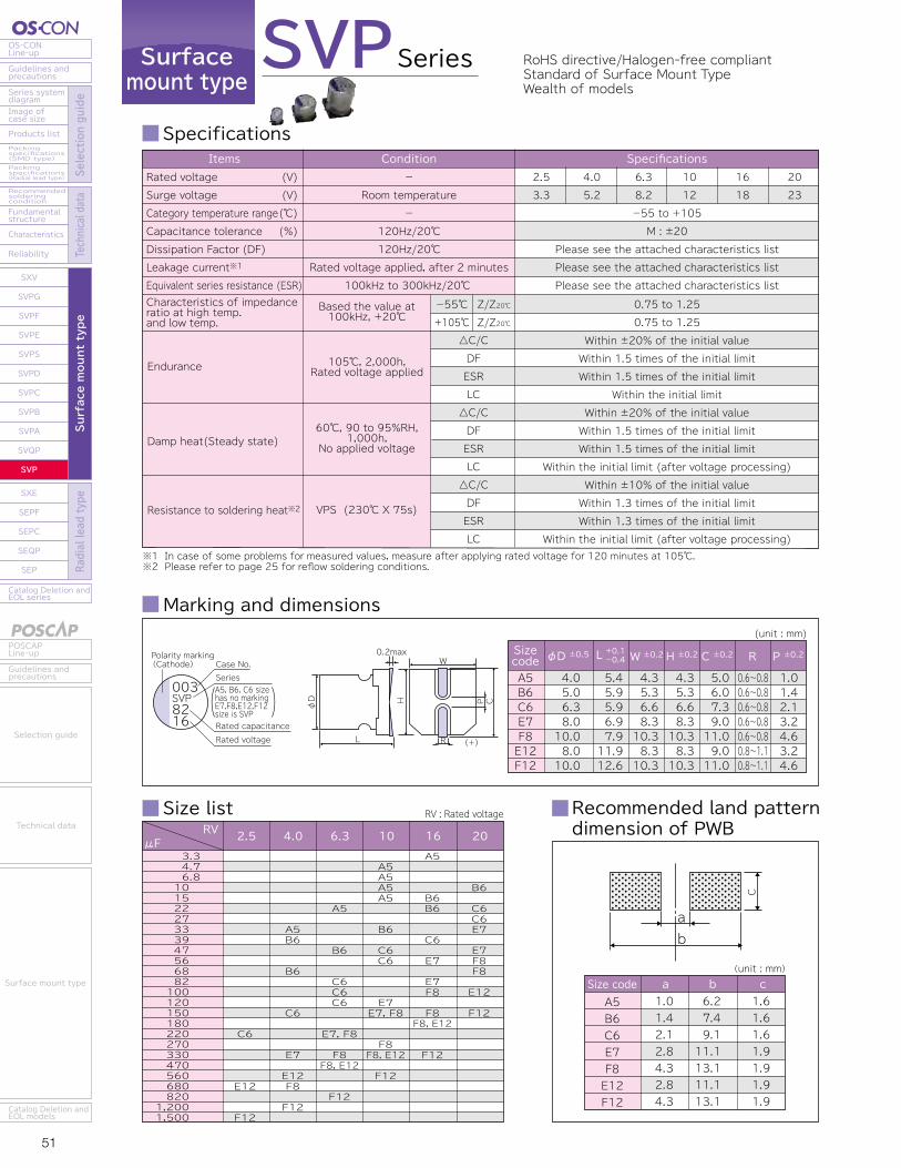
51 52
OS-CONLine-up
Guidelines andprecautions
Series systemdiagram
Recommendedsolderingcondition
Fundamentalstructure
Characteristics
Reliability
Catalog Deletion andEOL series
SXV
SVPG
SVPF
SVPE
SVPS
SVPD
SVPC
SVPB
SVPA
SVQP
SVP
SXE
SEPF
SEPC
SEQP
SEP
Image ofcase size
Products listPackingspecifications(SMD type)Packingspecifications(Radial lead type) Se
lection guide
Technical data
Surface mount type
Radial lead type
POSCAPLine-up
Guidelines andprecautions
Catalog Deletion andEOL models
Selection guide
Technical data
Surface mount type
Catalog Deletion andEOL series
SEP
SEQP
SEPC
SEPF
SXE
SXV
SVPG
SVPF
SVPE
SVPS
SVPD
SVPC
SVPB
SVPA
SVQP
SVP
Reliability
Characteristics
Fundamentalstructure
Recommendedsolderingcondition
Packingspecifications(Radial lead type)
Packingspecifications(SMD type)
Products list
Image ofcase size
Series systemdiagram
Guidelines andprecautions
OS-CONLine-up
Surface mount type
Radial lead type
Selection guide
Technical data
Guidelines andprecautions
POSCAPLine-up
Catalog Deletion andEOL models
Surface mount type
Technical data
Selection guide
Surfacemount type
Specifications SVP series characteristics list
RoHS directive/Halogen-free compliantStandard of Surface Mount TypeWealth of models
Frequency coefficient for ripple currentFrequencyCoefficient
120Hz≦ f <1kHz0.05
1kHz≦ f <10kHz0.3
10kHz≦ f <100kHz0.7
100kHz≦ f ≦500kHz1
Marking and dimensions
Size list
SVPSeries
※1 In case of some problems for measured values, measure after applying rated voltage for 120 minutes at 105℃.※2 Please refer to page 25 for reflow soldering conditions.
Endurance
Characteristics of impedanceratio at high temp. and low temp.
Damp heat(Steady state)
Resistance to soldering heat※2
△C/CDFESRLC△C/CDFESRLC△C/CDFESRLC
-55℃+105℃
Z/Z20℃Z/Z20℃
-55 to +105M : ±20
Please see the attached characteristics listPlease see the attached characteristics listPlease see the attached characteristics list
2.53.3
4.05.2
6.38.2
1012
1618
2023
SpecificationsItemsRated voltageSurge voltageCategory temperature rangeCapacitance toleranceDissipation Factor (DF)Leakage current※1
Equivalent series resistance (ESR)
(V)(V)(℃)(%)
105℃, 2,000h,Rated voltage applied
Based the value at100kHz, +20℃
60℃, 90 to 95%RH,1,000h,
No applied voltage
VPS (230℃ X 75s)
Condition-
Room temperature-
120Hz/20℃120Hz/20℃
Rated voltage applied, after 2 minutes100kHz to 300kHz/20℃
0.75 to 1.250.75 to 1.25
Within ±20% of the initial valueWithin 1.5 times of the initial limitWithin 1.5 times of the initial limit
Within the initial limitWithin ±20% of the initial valueWithin 1.5 times of the initial limitWithin 1.5 times of the initial limit
Within the initial limit (after voltage processing)Within ±10% of the initial valueWithin 1.3 times of the initial limitWithin 1.3 times of the initial limit
Within the initial limit (after voltage processing)
(unit : mm)
φD ±0.5 W ±0.2 H ±0.2 C ±0.2 R P ±0.2Sizecode L +0.1-0.4
A5B6C6E7F8E12F12
4.05.06.38.010.08.010.0
5.45.95.96.97.911.912.6
4.35.36.68.310.38.310.3
4.35.36.68.310.38.310.3
5.06.07.39.011.09.011.0
0.6~0.80.6~0.80.6~0.80.6~0.80.6~0.80.8~1.10.8~1.1
1.01.42.13.24.63.24.6
φD
L
P
R
C
W0.2max
H
(+)
003SVP8216
Case No.Polarity marking(Cathode)
Series
Rated capacitanceRated voltage
A5, B6, C6 size has no markingE7,F8,E12,F12 size is SVP
Recommended land pattern dimension of PWB
(unit : mm)Size codeA5B6C6E7F8E12F12
a b c1.01.42.12.84.32.84.3
6.27.49.111.113.111.113.1
1.61.61.61.91.91.91.9
C
ab
RV : Rated voltageRV
μF 3.3 4.7 6.810152227333947566882100120150180220270330470560680820
1,2001,500
4.0 6.3 10 16 202.5
A5B6
B6
C6
E7
E12F8
F12
A5
B6
C6C6C6
E7, F8
F8F8, E12
F12
A5A5A5A5
B6
C6C6
E7E7, F8
F8F8, E12
F12
A5
B6B6
C6
E7
E7F8
F8F8, E12
F12
B6
C6C6E7
E7F8F8
E12
F12
C6
E12
F12
16SVP3R3M10SVP4R7M10SVP6R8M10SVP10M10SVP15M6SVP22M4SVP33M20SVP10M16SVP15M16SVP22M10SVP33M6SVP47M4SVP39M4SVP68M20SVP22M20SVP27M16SVP39M10SVP47M10SVP56M6SVP82M6SVP100M6SVP120MV4SVP150MX2R5SVP220M20SVP33M20SVP47M16SVP56M16SVP82M10SVP120M10SVP150MX6SVP220MX4SVP330M20SVP56M20SVP68M16SVP100M16SVP150M16SVP180MX10SVP150M10SVP270M10SVP330MX6SVP220M6SVP330M6SVP470MX4SVP680M20SVP100M16SVP180M10SVP330M6SVP470M4SVP560M2R5SVP680M20SVP150M16SVP330M10SVP560M6SVP820M4SVP1200M2R5SVP1500M
1610101010
6.3 4.020161610
6.3 4.0 4.02020161010
6.3 6.3 6.3 4.0 2.5202016161010
6.3 4.02020161616101010
6.3 6.3 6.3 4.0201610
6.3 4.0 2.5201610
6.3 4.0 2.5
3.3 4.7 6.8 10 15 22 33 10 15 22 33 47 39 68 22 27 39 47 56 82100120150220 33 47 56 82120150220330 56 681001501801502703302203304706801001803304705606801503305608201200 1500
260240240220200200200120120 90 70 70 70 60 60 60 50 50 45 45 40 17 40 23 45 45 45 40 35 35 35 35 40 40 35 30 30 30 25 25 25 25 25 25 24 20 17 15 13 13 20 16 13 12 12 12
660 670 670 700 740 740 7401020102010601100110011001400145014501620162017001700181027801810239018901890189021202560256025602560240024002670302030203020370037003700370037003700332036403950421045204520432047205230544054405440
7.08.09.01010121510101012121212101010121212121212121212121212121212121212121212121212121212151515151515151515151818
26.4 23.5 34 50 75 69.3 66 100 120 176 165 148 78 136 88 108 125 94 112 103 126 151 120 110 132 188 179 262 240 300 277 264 224 272 320 480 576 300 540 660 277 416 592 544 400 576 660 592 448 340 600 792 840 775 960 750
Sizecode
ESR(mΩ) (max)100kHz to 300kHz/20℃
Ratedripple current
100kHz (mArms) at 105℃ DF
(% max)Ratedvoltage(V)
Leakage current (μA)(max) After 2 minutes
Ratedcapacitance
(μF)Part number
A5
B6
C6
E7
F8
E12
F12
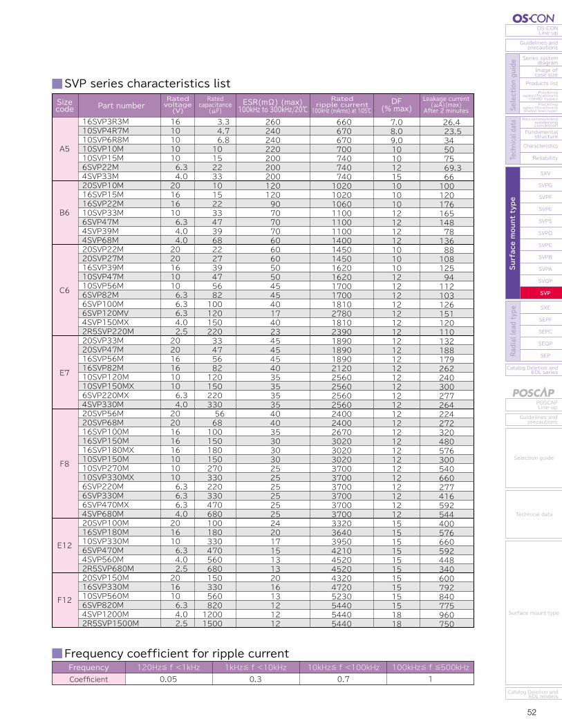
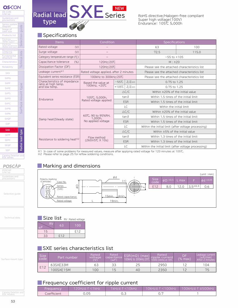
53 54
OS-CONLine-up
Guidelines andprecautions
Series systemdiagram
Recommendedsolderingcondition
Fundamentalstructure
Characteristics
Reliability
Catalog Deletion andEOL series
SXV
SVPG
SVPF
SVPE
SVPS
SVPD
SVPC
SVPB
SVPA
SVQP
SVP
SXE
SEPF
SEPC
SEQP
SEP
Image ofcase size
Products listPackingspecifications(SMD type)Packingspecifications(Radial lead type) Se
lection guide
Technical data
Surface mount type
Radial lead type
POSCAPLine-up
Guidelines andprecautions
Catalog Deletion andEOL models
Selection guide
Technical data
Surface mount type
Catalog Deletion andEOL series
SEP
SEQP
SEPC
SEPF
SXE
SXV
SVPG
SVPF
SVPE
SVPS
SVPD
SVPC
SVPB
SVPA
SVQP
SVP
Reliability
Characteristics
Fundamentalstructure
Recommendedsolderingcondition
Packingspecifications(Radial lead type)
Packingspecifications(SMD type)
Products list
Image ofcase size
Series systemdiagram
Guidelines andprecautions
OS-CONLine-up
Surface mount type
Radial lead type
Selection guide
Technical data
Guidelines andprecautions
POSCAPLine-up
Catalog Deletion andEOL models
Surface mount type
Technical data
Selection guide
Radial leadtype
Specifications
RoHS directive/Halogen-free compliantSuper high voltage(100V)Endurance: 105℃ 5,000h
Frequency coefficient for ripple currentFrequencyCoefficient
120Hz≦ f <1kHz0.05
1kHz≦ f <10kHz0.3
10kHz≦ f <100kHz0.7
100kHz≦ f ≦500kHz1
SXESeries
Marking and dimensions
E12 8.0
L max F
12.0
φd ±0.05
3.5±0.3
(unit : mm)
φD ±0.5Sizecode
0.6
φd
L15min. 4min.
19min.
φD F
(+)
227SXE3363
Case No.Polarity marking(Cathode)
Series
Rated capacitance
Rated voltage
Size list RV : Rated voltageRV
μF 63 100
1533 E12
E12
SXE series characteristics list
E1263SXE33M100SXE15M
63100
33 15
2540
29502350
1212
104 75
Sizecode
ESR(mΩ) (max)100kHz to 300kHz/20℃
Ratedripple current100kHz (mArms) at 105℃
DF(% max)
Ratedvoltage(V)
Leakage current (μA)(max) After 2 minutes
Part numberRated
capacitance(μF)
(SXE)
Endurance 105℃, 5,000h,Rated voltage applied
Characteristics of impedanceratio at high temp. and low temp.
Based the value at100kHz, +20℃
Damp heat(Steady state)60℃, 90 to 95%RH,
1,000h,No applied voltage
Resistance to soldering heat※2 Flow method (260±5℃ X 10s)
△C/CtanδESRLC△C/CtanδESRLC△C/CtanδESRLC
-55℃
+105℃Z/Z20℃
Z/Z20℃
-55 to +105
M : ±20
Please see the attached characteristics list
Please see the attached characteristics list
Please see the attached characteristics list
6372.5
100115.0
SpecificationsConditionItems
0.75 to 1.25
0.75 to 1.25
Within ±20% of the initial value
Within 1.5 times of the initial limit
Within 1.5 times of the initial limit
Within the initial limit
Within ±20% of the initial value
Within 1.5 times of the initial limit
Within 1.5 times of the initial limit
Within the initial limit (after voltage processing)
Within ±5% of the initial value
Within 1.3 times of the initial limit
Within 1.3 times of the initial limit
Within the initial limit (after voltage processing)
Rated voltage
Surge voltage
Category temperature range
Capacitance tolerance
Dissipation Factor (DF)
Leakage current※1
Equivalent series resistance (ESR)
---
120Hz/20℃120Hz/20℃
Rated voltage applied, after 2 minutes100kHz to 300kHz/20℃
(V)(V)(℃)(%)
※1 In case of some problems for measured values, measure after applying rated voltage for 120 minutes at 105℃.※2 Please refer to page 25 for reflow soldering conditions.
NEW
Radial leadtype
Specifications
RoHS directive/Halogen-free compliantHigh voltage(35V)Large capacitance(1,000μF)Endurance: 105℃ 5,000h
Frequency coefficient for ripple currentFrequencyCoefficient
120Hz≦ f <1kHz0.05
1kHz≦ f <10kHz0.3
10kHz≦ f <100kHz0.7
100kHz≦ f ≦500kHz1
SEPF Series
SEPF series characteristics list
E12
C55
C6
E7
F13
32SEPF22M16SEPF150M35SEPF22M25SEPF56M20SEPF120M16SEPF180M35SEPF39M32SEPF68M25SEPF82M20SEPF180M16SEPF270M35SEPF82M25SEPF180M20SEPF390M16SEPF560M35SEPF120M25SEPF330M20SEPF560M16SEPF1000M
32163525201635322520163525201635252016
221502256120180396882180270821803905601203305601000
35303530252230252825222016141418141212
2400259026002800320033002800320030003200330040004650495049504400500054005400
12121212121212101212121212121212121212
14048015428048057627343541072086457490015601792840165022403200
Sizecode
DF(% max)
Ratedvoltage(V)
Leakage current (μA)(max)
After 2 minutesESR(mΩ) (max)100kHz to 300kHz/20℃
Ratedripple current100kHz (mArms) at 105℃
Ratedcapacitance
(μF)Part number
Marking and dimensions Size list RV : Rated voltageRV
μF 16 20 25 32
2239566882120150180270330390560
1,000
C55C6E7
E12F13
C6
E7
E12F13
C6
E7
E12
F13
C55
E7
35
C6E7
E12F13
φd
L15min. 4min.
19min.
φD F
(+)
223SEPF6832
Case No.Polarity marking(Cathode)
Series
Rated capacitance
Rated voltage
(SEPF)
C55C6E7E12F13
6.36.38.08.010.0
L max F
5.56.07.012.013.0
φd ±0.05
2.5±0.52.5±0.53.5±0.53.5±0.55.0±0.5
(unit : mm)
φD ±0.5Sizecode
0.450.50.50.6 0.6
※3 32SEPF68M is 0.6±0.05
※
※1 In case of some problems for measured values, measure after applying rated voltage for 120 minutes at 105℃.※2 Please refer to page 25 for flow soldering conditions.
Endurance
Characteristics of impedanceratio at high temp. and low temp.
Damp heat(Steady state)
Resistance to soldering heat※2
△C/CDFESRLC△C/CDFESRLC△C/CDFESRLC
-55℃+105℃
Z/Z20℃Z/Z20℃
-55 to +105M : ±20
Please see the attached characteristics listPlease see the attached characteristics listPlease see the attached characteristics list
1618
2023
2529
3237
3540
SpecificationsItemsRated voltageSurge voltageCategory temperature rangeCapacitance toleranceDissipation Factor (DF)Leakage current※1Equivalent series resistance (ESR)
(V)(V)(℃)(%)
105℃, 5,000h,Rated voltage applied
Based the value at100kHz, +20℃
60℃, 90 to 95%RH,1,000h,
No-applied voltage
Flow method (260±5℃ X 10s)
Condition-
Room temperature-
120Hz/20℃120Hz/20℃
Rated voltage applied, after 2 minutes100kHz to 300kHz/20℃
0.75 to 1.250.75 to 1.25
Within ±20% of the initial valueWithin 1.5 times of the initial limitWithin 1.5 times of the initial limit
Within the initial limitWithin ±20% of the initial valueWithin 1.5 times of the initial limitWithin 1.5 times of the initial limit
Within the initial limit (after voltage processing)Within ±5% of the initial value
Within the initial limitWithin the initial limit
Within the initial limit (after voltage processing)
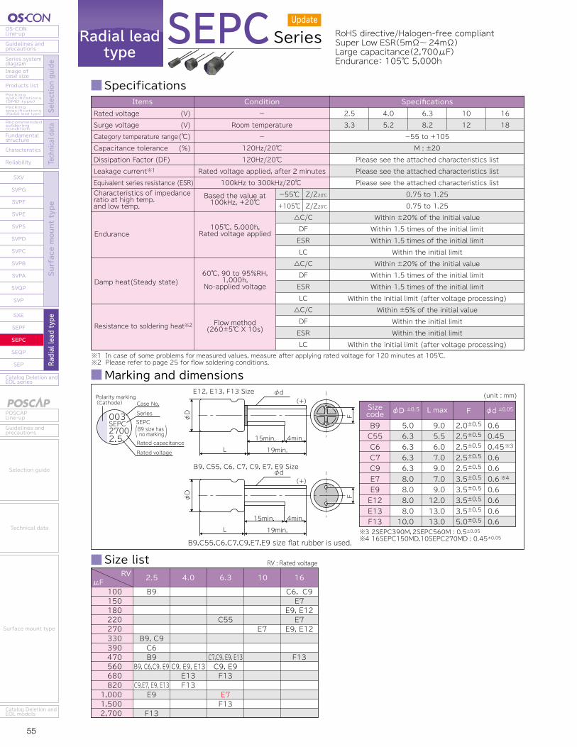
55 56
OS-CONLine-up
Guidelines andprecautions
Series systemdiagram
Recommendedsolderingcondition
Fundamentalstructure
Characteristics
Reliability
Catalog Deletion andEOL series
SXV
SVPG
SVPF
SVPE
SVPS
SVPD
SVPC
SVPB
SVPA
SVQP
SVP
SXE
SEPF
SEPC
SEQP
SEP
Image ofcase size
Products listPackingspecifications(SMD type)Packingspecifications(Radial lead type) Se
lection guide
Technical data
Surface mount type
Radial lead type
POSCAPLine-up
Guidelines andprecautions
Catalog Deletion andEOL models
Selection guide
Technical data
Surface mount type
Catalog Deletion andEOL series
SEP
SEQP
SEPC
SEPF
SXE
SXV
SVPG
SVPF
SVPE
SVPS
SVPD
SVPC
SVPB
SVPA
SVQP
SVP
Reliability
Characteristics
Fundamentalstructure
Recommendedsolderingcondition
Packingspecifications(Radial lead type)
Packingspecifications(SMD type)
Products list
Image ofcase size
Series systemdiagram
Guidelines andprecautions
OS-CONLine-up
Surface mount type
Radial lead type
Selection guide
Technical data
Guidelines andprecautions
POSCAPLine-up
Catalog Deletion andEOL models
Surface mount type
Technical data
Selection guide
Update
Radial leadtype
Series
Specifications SEPC series characteristics list
SEPC RoHS directive/Halogen-free compliantSuper Low ESR(5mΩ~24mΩ)Large capacitance(2,700μF)Endurance: 105℃ 5,000h
Frequency coefficient for ripple currentFrequencyCoefficient
120Hz≦ f <1kHz0.05
1kHz≦ f <10kHz0.3
10kHz≦ f <100kHz0.7
100kHz≦ f ≦500kHz1
Marking and dimensions
Size list
※1 In case of some problems for measured values, measure after applying rated voltage for 120 minutes at 105℃.※2 Please refer to page 25 for flow soldering conditions.
Endurance
Characteristics of impedanceratio at high temp. and low temp.
Damp heat(Steady state)
Resistance to soldering heat※2
△C/CDFESRLC△C/CDFESRLC△C/CDFESRLC
-55℃+105℃
Z/Z20℃Z/Z20℃
-55 to +105M : ±20
Please see the attached characteristics listPlease see the attached characteristics listPlease see the attached characteristics list
2.53.3
4.05.2
6.38.2
1012
1618
SpecificationsItemsRated voltageSurge voltageCategory temperature rangeCapacitance toleranceDissipation Factor (DF)Leakage current※1
Equivalent series resistance (ESR)
(V)(V)(℃)(%)
105℃, 5,000h,Rated voltage applied
Based the value at100kHz, +20℃
60℃, 90 to 95%RH,1,000h,
No-applied voltage
Flow method (260±5℃ X 10s)
Condition-
Room temperature-
120Hz/20℃120Hz/20℃
Rated voltage applied, after 2 minutes100kHz to 300kHz/20℃
0.75 to 1.250.75 to 1.25
Within ±20% of the initial valueWithin 1.5 times of the initial limitWithin 1.5 times of the initial limit
Within the initial limitWithin ±20% of the initial valueWithin 1.5 times of the initial limitWithin 1.5 times of the initial limit
Within the initial limit (after voltage processing)Within ±5% of the initial value
Within the initial limitWithin the initial limit
Within the initial limit (after voltage processing)
RV : Rated voltageRV
μF 2.5 4.0 6.3 16
100150180220270330390470560680820
1,0001,5002,700
B9
B9, C9C6B9
B9, C6,C9, E9
C9,E7, E9, E13E9
F13
C9, E9, E13E13F13
C55
C7,C9, E9, E13C9, E9F13
E7F13
10
E7
C6, C9E7
E9, E12E7
E9, E12
F13
B9C55C6C7C9E7E9E12E13F13
5.06.36.36.36.38.08.08.08.010.0
L max F
9.05.56.07.09.07.09.012.013.013.0
φd ±0.05
2.0±0.52.5±0.52.5±0.52.5±0.52.5±0.53.5±0.53.5±0.53.5±0.53.5±0.55.0±0.5
(unit : mm)
φD ±0.5Sizecode
0.6 0.450.450.6 0.6 0.6 0.6 0.6 0.6 0.6
※3 2SEPC390M,2SEPC560M : 0.5±0.05※4 16SEPC150MD,10SEPC270MD : 0.45±0.05
※3
※4
B9,C55,C6,C7,C9,E7,E9 size flat rubber is used.
E12, E13, F13 Size φd
L15min. 4min.
19min.
φD F
(+)
B9, C55, C6, C7, C9, E7, E9 Sizeφd
L15min. 4min.
19min.
φD F
(+)
003SEPC27002.5
Case No.Polarity marking(Cathode)
Series
Rated capacitance
Rated voltage
SEPC
( )B9 size has no marking
※ Red letters : New models
E9
C6
C7
C55
C9
E7
B9
E12
E13
F13
2SEPC100MZ
2SEPC330MZ
2SEPC470MZ
2SEPC560MZ
6SEPC220M
16SEPC100M
2SEPC390M
2SEPC560M
6SEPC470ME
16SEPC100MW
6SEPC470MW
6SEPC560MW
4SEPC560MW
2SEPC330MW
2SEPC560MW
2SEPC820MW
16SEPC150MD
16SEPC220MD
10SEPC270MD
2SEPC820MD
6SEPC1000MD
16SEPC180MX
16SEPC270MX
6SEPC470MX
6SEPC560MX
4SEPC560MX
2SEPC560MX
2SEPC820MX
2SEPC820MY
2SEPC1000MX
16SEPC180M
16SEPC270M
6SEPC470M
4SEPC560M
4SEPC680M
2R5SEPC820M
16SEPC470M
6SEPC680M
6SEPC1500M
4SEPC820M
2SEPC2700M
2.5
2.5
2.5
2.5
6.3
16
2.5
2.5
6.3
16
6.3
6.3
4.0
2.5
2.5
2.5
16
16
10
2.5
6.3
16
16
6.3
6.3
4.0
2.5
2.5
2.5
2.5
16
16
6.3
4.0
4.0
2.5
16
6.3
6.3
4.0
2.5
100
330
470
560
220
100
390
560
470
100
470
560
560
330
560
820
150
220
270
820
1000
180
270
470
560
560
560
820
820
1000
180
270
470
560
680
820
470
680
1500
820
2700
7
7
7
7
18
24
10
10
20
10
7
7
7
7
7
7
22
13
22
8
18
10
10
8
7
7
8
7
5
7
16
11
8
7
7
7
10
7
10
7
10
4180
4180
4180
4180
2980
2490
3900
3900
2970
4680
5600
5600
5600
5600
5600
5600
3220
4150
3220
5300
3530
5000
5000
5700
6100
6100
4700
6100
7200
6100
4360
5000
5700
6100
6100
6100
6100
6640
5560
6640
5560
10
10
10
10
12
10
12
12
10
10
10
10
10
10
10
10
12
10
12
10
10
10
10
10
10
10
10
10
10
10
10
10
10
10
10
10
10
10
10
10
10
500
500
500
500
280
320
500
500
592
500
592
705
500
500
500
500
500
500
500
500
1260
576
864
592
705
500
280
500
500
500
576
864
592
500
544
500
1504
857
1890
656
1350
Sizecode
DF(% max)
Ratedvoltage(V)
Leakage current (μA)(max)
After 2 minutesESR(mΩ) (max)100kHz to 300kHz/20℃
Ratedripple current100kHz (mArms) at 105℃
Ratedcapacitance
(μF)Part number

57 58
OS-CONLine-up
Guidelines andprecautions
Series systemdiagram
Recommendedsolderingcondition
Fundamentalstructure
Characteristics
Reliability
Catalog Deletion andEOL series
SXV
SVPG
SVPF
SVPE
SVPS
SVPD
SVPC
SVPB
SVPA
SVQP
SVP
SXE
SEPF
SEPC
SEQP
SEP
Image ofcase size
Products listPackingspecifications(SMD type)Packingspecifications(Radial lead type) Se
lection guide
Technical data
Surface mount type
Radial lead type
POSCAPLine-up
Guidelines andprecautions
Catalog Deletion andEOL models
Selection guide
Technical data
Surface mount type
Catalog Deletion andEOL series
SEP
SEQP
SEPC
SEPF
SXE
SXV
SVPG
SVPF
SVPE
SVPS
SVPD
SVPC
SVPB
SVPA
SVQP
SVP
Reliability
Characteristics
Fundamentalstructure
Recommendedsolderingcondition
Packingspecifications(Radial lead type)
Packingspecifications(SMD type)
Products list
Image ofcase size
Series systemdiagram
Guidelines andprecautions
OS-CONLine-up
Surface mount type
Radial lead type
Selection guide
Technical data
Guidelines andprecautions
POSCAPLine-up
Catalog Deletion andEOL models
Surface mount type
Technical data
Selection guide
Radial leadtype
Series
Specifications SEQP series characteristics list
SEQP RoHS directive/Halogen-free compliantHigh voltage(32V)Endurance: 125℃ 1,000h, 105℃ 5,000h
Frequency coefficient for ripple currentFrequencyCoefficient
120Hz≦ f <1kHz0.05
1kHz≦ f <10kHz0.3
10kHz≦ f <100kHz0.7
100kHz≦ f ≦500kHz1
Marking and dimensions
Size list RV : Rated voltageRV
μF 4.0 6.3 10 16 20 32
6.81518223947566882100120150180270330470560680820
1,200
C6
E7
E12F8
F13
C6
E7
F8E12
F13
C6
E7
F8E12
F13
C6
E7
F8E12
F13
C6
E7
F8
E12
F13
E7F8E12
C6E7F8E12F13
6.38.010.08.010.0
L max F
6.07.08.012.013.0
φd ±0.05
2.5±0.53.5±0.55.0±0.53.5±0.55.0±0.5
(unit : mm)
φD ±0.5Sizecode
0.450.450.500.600.60
φd
L15min. 4min.
19min.
φD F
(+)
003SEQP1532
Case No.Polarity marking(Cathode)
Series(SEQP)
Rated capacitance
Rated voltage
※1 In case of some problems for measured values, measure after applying rated voltage for 120 minutes at 125℃.※2 Please refer to page 25 for flow soldering conditions.
Endurance
Characteristics of impedanceratio at high temp. and low temp.
Damp heat(Steady state)
Resistance to soldering heat※2
△C/CDFESRLC△C/CDFESRLC△C/CDFESRLC
-55℃+125℃
Z/Z20℃Z/Z20℃
-55 to +125M : ±20
Please see the attached characteristics listPlease see the attached characteristics listPlease see the attached characteristics list
4.05.2
6.38.4
1012
1618
2023
3237
SpecificationsItemsRated voltageSurge voltageCategory temperature rangeCapacitance toleranceDissipation Factor (DF)Leakage current※1
Equivalent series resistance (ESR)
(V)(V)(℃)(%)
125℃, 1,000h,105℃, 5,000h,
Rated voltage applied
Based the value at100kHz, +20℃
60℃, 90 to 95%RH,1,000h,
No-applied voltage
Flow method (260±5℃ X 10s)
Condition-
Room temperature-
120Hz/20℃120Hz/20℃
Rated voltage applied, after 2 minutes100kHz to 300kHz/20℃
0.75 to 1.250.75 to 1.25
Within ±20% of the initial valueWithin 2 times of the initial limitWithin 2 times of the initial limit
Within the initial limitWithin ±20% of the initial valueWithin 1.5 times of the initial limitWithin 1.5 times of the initial limit
Within the initial limit (after voltage processing)Within ±5% of the initial value
Within the initial limitWithin the initial limit
Within the initial limit (after voltage processing)
※1 Tx : Ambient temperature
C6
E7
F8
E12
F13
20SEQP22M
16SEQP39M
10SEQP56M
6SEQP82M
4SEQP150M
32SEQP6R8M
20SEQP47M
16SEQP82M
10SEQP120M
6SEQP150M
4SEQP330M
32SEQP15M
20SEQP68M
16SEQP150M
10SEQP270M
6SEQP330M
4SEQP680M
32SEQP18M
20SEQP100M
16SEQP180M
10SEQP330M
6SEQP470M
4SEQP560M
20SEQP150M
16SEQP330M
10SEQP560M
6SEQP820M
4SEQP1200M
20
16
10
6.3
4.0
32
20
16
10
6.3
4.0
32
20
16
10
6.3
4.0
32
20
16
10
6.3
4.0
20
16
10
6.3
4.0
22
39
56
82
150
6.8
47
82
120
150
330
15
68
150
270
330
680
18
100
180
330
470
560
150
330
560
820
1200
60
50
45
45
40
100
45
40
35
35
35
80
40
30
25
25
25
50
24
20
17
15
13
20
16
13
12
12
458
512
537
537
572
440
598
670
810
810
810
560
759
955
1170
1170
1170
790
1050
1151
1250
1332
1430
1367
1493
1655
1721
1721
1450
1620
1700
1700
1810
1400
1890
2120
2560
2560
2560
1800
2400
3020
3700
3700
3700
2500
3320
3640
3950
4210
4520
4320
4720
5230
5440
5440
10
10
12
12
12
10
12
12
12
12
12
10
12
12
12
12
12
12
15
15
15
15
15
15
15
15
15
18
220
312
280
258
300
44
470
656
600
472
660
96
272
480
540
416
544
115
400
576
660
592
448
600
792
840
775
960
Sizecode
ESR(mΩ) (max)100kHz to 300kHz/20℃ 100kHz(mArms)
105℃<Tx≦125℃※1 Tx≦105℃※1
DF(% max)
Ratedvoltage(V)
Ratedcapacitance
(μF)
Leakage current (μA)(max) After 2 minutes
Rated ripple current Allowable ripple currentPart number
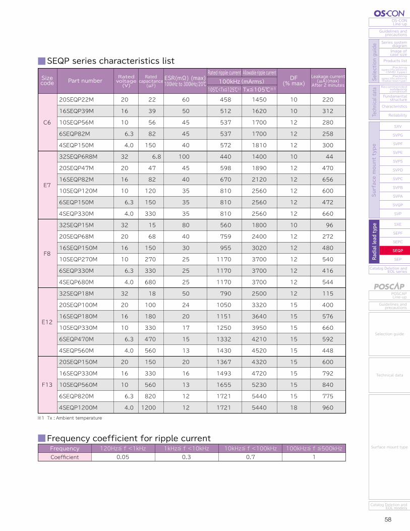

59 60
OS-CONLine-up
Guidelines andprecautions
Series systemdiagram
Recommendedsolderingcondition
Fundamentalstructure
Characteristics
Reliability
Catalog Deletion andEOL series
SXV
SVPG
SVPF
SVPE
SVPS
SVPD
SVPC
SVPB
SVPA
SVQP
SVP
SXE
SEPF
SEPC
SEQP
SEP
Image ofcase size
Products listPackingspecifications(SMD type)Packingspecifications(Radial lead type) Se
lection guide
Technical data
Surface mount type
Radial lead type
POSCAPLine-up
Guidelines andprecautions
Catalog Deletion andEOL models
Selection guide
Technical data
Surface mount type
Catalog Deletion andEOL series
SEP
SEQP
SEPC
SEPF
SXE
SXV
SVPG
SVPF
SVPE
SVPS
SVPD
SVPC
SVPB
SVPA
SVQP
SVP
Reliability
Characteristics
Fundamentalstructure
Recommendedsolderingcondition
Packingspecifications(Radial lead type)
Packingspecifications(SMD type)
Products list
Image ofcase size
Series systemdiagram
Guidelines andprecautions
OS-CONLine-up
Surface mount type
Radial lead type
Selection guide
Technical data
Guidelines andprecautions
POSCAPLine-up
Catalog Deletion andEOL models
Surface mount type
Technical data
Selection guide
Radial leadtype
Specifications SEP series characteristics list
RoHS directive/Halogen-free compliantStandard of Radial Lead TypeEndurance: 105℃ 3,000h
Frequency coefficient for ripple currentFrequencyCoefficient
120Hz≦ f <1kHz0.05
1kHz≦ f <10kHz0.3
10kHz≦ f <100kHz0.7
100kHz≦ f ≦500kHz1
Marking and dimensions
Size list RV : Rated voltage※1 Tx : Ambient temperature
SEP Series
※1 In case of some problems for measured values, measure after applying rated voltage.※2 Please refer to page 25 for flow soldering conditions.
Endurance
Characteristics of impedanceratio at high temp. and low temp.
Damp heat(Steady state)
Resistance to soldering heat※2
△C/CDFESRLC△C/CDFESRLC△C/CDFESRLC
-55℃+105℃
Z/Z20℃Z/Z20℃
-55 to +105M : ±20
Please see the attached characteristics listPlease see the attached characteristics listPlease see the attached characteristics list
2.53.3
4.05.2
6.38.2
1012
1618
2023
SpecificationsItemsRated voltageSurge voltageCategory temperature rangeCapacitance toleranceDissipation Factor (DF)Leakage current※1
Equivalent series resistance (ESR)
(V)(V)(℃)(%)
105℃, 3,000h,Rated voltage applied(2.5V → 2,000h)
Based the value at100kHz, +20℃
60℃, 90 to 95%RH,1,000h,
No-applied voltage
Flow method (260±5℃ X 10s)
Condition-
Room temperature-
120Hz/20℃120Hz/20℃
Rated voltage applied, after 2 minutes100kHz to 300kHz/20℃
0.75 to 1.250.75 to 1.25
Within ±20% of the initial valueWithin 1.5 times of the initial limitWithin 1.5 times of the initial limit
Within the initial limitWithin ±20% of the initial valueWithin 1.5 times of the initial limitWithin 1.5 times of the initial limit
Within the initial limit (after voltage processing)Within ±5% of the initial value
Within the initial limitWithin the initial limit
Within the initial limit (after voltage processing)
RVμF 2.5 4.0 6.3 10 16 20
22333947566882100120150180220270330470560680820
1,2001,500
E12
F13
C6
C6
E7
E7F8E12F8
F13
C6
E7
F8E12
F13
C6
E7
F8E12
F13
C6
E7
F8E12
F13
C6E7
E7F8F8
F8、E12
F13
C6E7F8E12F13
6.38.010.08.010.0
L max F
6.07.08.012.013.0
φd ±0.05
2.5±0.53.5±0.55.0±0.53.5±0.55.0±0.5
(unit : mm)
φD ±0.5Sizecode
0.450.450.500.600.60
φd
L15min. 4min.
19min.
φD F
(+)003SEP8206
Case No.Polarity marking(Cathode)
Series
Rated capacitance
Rated voltage
(SEP)
C6
20SEP22M16SEP39M10SEP56M6SEP82M4SEP100M4SEP150M20SEP33M20SEP47M16SEP82M16SEP270M10SEP120M6SEP150M4SEP220M4SEP330M20SEP56M20SEP68M20SEP100MX16SEP150M10SEP270M6SEP330M4SEP470M4SEP680M20SEP100M16SEP180M10SEP330M6SEP470M4SEP560M2R5SEP680M20SEP150M16SEP330M10SEP560M6SEP820M4SEP1200M2R5SEP1500M
201610
6.3 4.0 4.02020161610
6.3 4.0 4.02020201610
6.3 4.0 4.0201610
6.3 4.0 2.5201610
6.3 4.0 2.5
22 39 56 82100150 33 47 82270120150220330 56 681001502703304706801001803304705606801503305608201200 1500
60504545404045454014353535354040353025252525242017151313201613121212
1450162017001700181018101890189021205050256025602560256024002400257030203700370037003700332036403950421045204520432047205230544054405440
10101212121212121215121212121212121212121212151515151515151515151818
220312280258200300330470656864600472440660224272400480540416376544400576660592448340600792840775960750
Sizecode
E7
F8
E12
F13
Ratedripple current
100kHz (mArms) at 105℃DF
(% max)Ratedvoltage(V)
Leakage current (μA)(max) After 2 minutes
Ratedcapacitance
(μF)Part number ESR(mΩ) (max)
100kHz to 300kHz/20℃
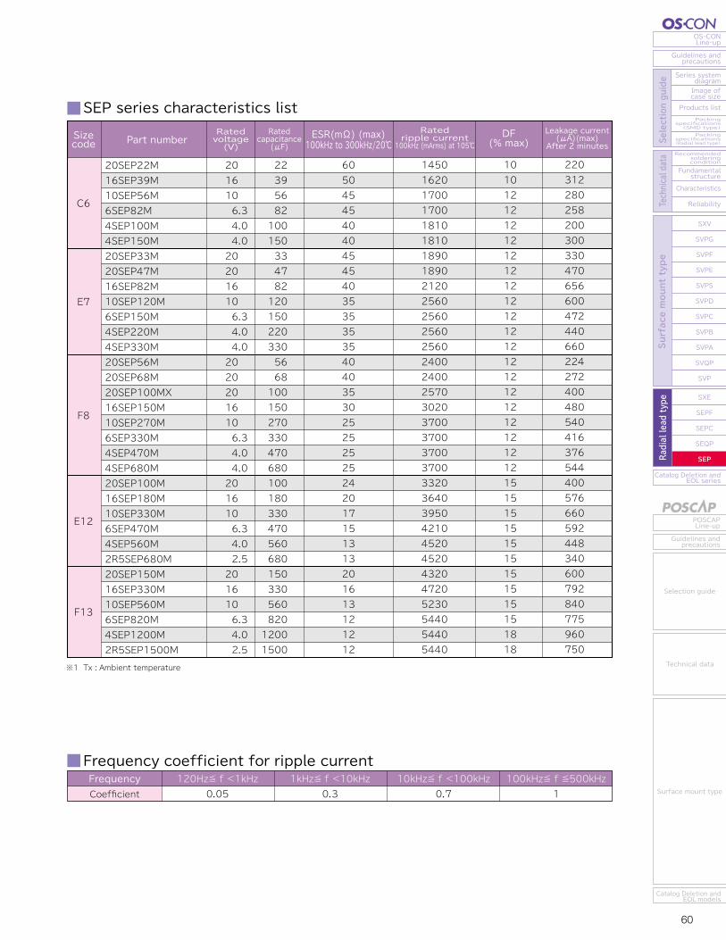
59 60
OS-CONLine-up
Guidelines andprecautions
Series systemdiagram
Recommendedsolderingcondition
Fundamentalstructure
Characteristics
Reliability
Catalog Deletion andEOL series
SXV
SVPG
SVPF
SVPE
SVPS
SVPD
SVPC
SVPB
SVPA
SVQP
SVP
SXE
SEPF
SEPC
SEQP
SEP
Image ofcase size
Products listPackingspecifications(SMD type)Packingspecifications(Radial lead type) Se
lection guide
Technical data
Surface mount type
Radial lead type
POSCAPLine-up
Guidelines andprecautions
Catalog Deletion andEOL models
Selection guide
Technical data
Surface mount type
Catalog Deletion andEOL series
SEP
SEQP
SEPC
SEPF
SXE
SXV
SVPG
SVPF
SVPE
SVPS
SVPD
SVPC
SVPB
SVPA
SVQP
SVP
Reliability
Characteristics
Fundamentalstructure
Recommendedsolderingcondition
Packingspecifications(Radial lead type)
Packingspecifications(SMD type)
Products list
Image ofcase size
Series systemdiagram
Guidelines andprecautions
OS-CONLine-up
Surface mount type
Radial lead type
Selection guide
Technical data
Guidelines andprecautions
POSCAPLine-up
Catalog Deletion andEOL models
Surface mount type
Technical data
Selection guide
Radial leadtype
Specifications SEP series characteristics list
RoHS directive/Halogen-free compliantStandard of Radial Lead TypeEndurance: 105℃ 3,000h
Frequency coefficient for ripple currentFrequencyCoefficient
120Hz≦ f <1kHz0.05
1kHz≦ f <10kHz0.3
10kHz≦ f <100kHz0.7
100kHz≦ f ≦500kHz1
Marking and dimensions
Size list RV : Rated voltage ※1 Tx : Ambient temperature
SEP Series
※1 In case of some problems for measured values, measure after applying rated voltage.※2 Please refer to page 25 for flow soldering conditions.
Endurance
Characteristics of impedanceratio at high temp. and low temp.
Damp heat(Steady state)
Resistance to soldering heat※2
△C/CDFESRLC△C/CDFESRLC△C/CDFESRLC
-55℃+105℃
Z/Z20℃Z/Z20℃
-55 to +105M : ±20
Please see the attached characteristics listPlease see the attached characteristics listPlease see the attached characteristics list
2.53.3
4.05.2
6.38.2
1012
1618
2023
SpecificationsItemsRated voltageSurge voltageCategory temperature rangeCapacitance toleranceDissipation Factor (DF)Leakage current※1
Equivalent series resistance (ESR)
(V)(V)(℃)(%)
105℃, 3,000h,Rated voltage applied(2.5V → 2,000h)
Based the value at100kHz, +20℃
60℃, 90 to 95%RH,1,000h,
No-applied voltage
Flow method (260±5℃ X 10s)
Condition-
Room temperature-
120Hz/20℃120Hz/20℃
Rated voltage applied, after 2 minutes100kHz to 300kHz/20℃
0.75 to 1.250.75 to 1.25
Within ±20% of the initial valueWithin 1.5 times of the initial limitWithin 1.5 times of the initial limit
Within the initial limitWithin ±20% of the initial valueWithin 1.5 times of the initial limitWithin 1.5 times of the initial limit
Within the initial limit (after voltage processing)Within ±5% of the initial value
Within the initial limitWithin the initial limit
Within the initial limit (after voltage processing)
RVμF 2.5 4.0 6.3 10 16 20
22333947566882100120150180220270330470560680820
1,2001,500
E12
F13
C6
C6
E7
E7F8E12F8
F13
C6
E7
F8E12
F13
C6
E7
F8E12
F13
C6
E7
F8E12
F13
C6E7
E7F8F8
F8、E12
F13
C6E7F8E12F13
6.38.010.08.010.0
L max F
6.07.08.012.013.0
φd ±0.05
2.5±0.53.5±0.55.0±0.53.5±0.55.0±0.5
(unit : mm)
φD ±0.5Sizecode
0.450.450.500.600.60
φd
L15min. 4min.
19min.
φD F
(+)003SEP8206
Case No.Polarity marking(Cathode)
Series
Rated capacitance
Rated voltage
(SEP)
C6
Sizecode
E7
F8
E12
F13
Ratedripple current
100kHz (mArms) at 105℃DF
(% max)Ratedvoltage(V)
Leakage current (μA)(max) After 2 minutes
Ratedcapacitance
(μF)Part number ESR(mΩ) (max)
100kHz to 300kHz/20℃
20SEP22M16SEP39M10SEP56M6SEP82M4SEP100M4SEP150M20SEP33M20SEP47M16SEP82M10SEP120M6SEP150M4SEP220M4SEP330M20SEP56M20SEP68M20SEP100MX16SEP150M10SEP270M6SEP330M4SEP470M4SEP680M20SEP100M16SEP180M10SEP330M6SEP470M4SEP560M2R5SEP680M20SEP150M16SEP330M10SEP560M6SEP820M4SEP1200M2R5SEP1500M
201610
6.3 4.0 4.020201610
6.3 4.0 4.02020201610
6.3 4.0 4.0201610
6.3 4.0 2.5201610
6.3 4.0 2.5
22 39 56 82100150 33 47 82120150220330 56 681001502703304706801001803304705606801503305608201200 1500
605045454040454540353535354040353025252525242017151313201613121212
145016201700170018101810189018902120256025602560256024002400257030203700370037003700332036403950421045204520432047205230544054405440
101012121212121212121212121212121212121212151515151515151515151818
220312280258200300330470656600472440660224272400480540416376544400576660592448340600792840775960750
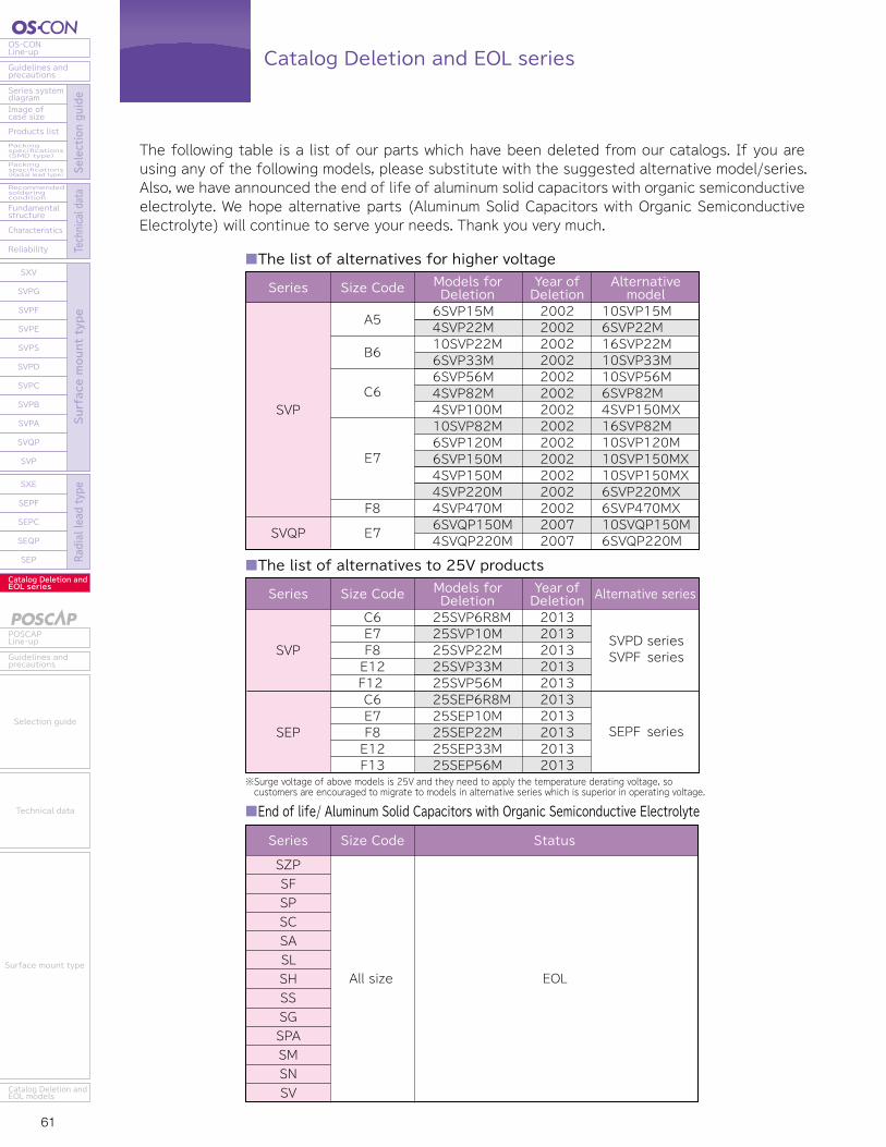
61 62
Catalog Deletion and EOL seriesOS-CONLine-up
Guidelines andprecautions
Series systemdiagram
Recommendedsolderingcondition
Fundamentalstructure
Characteristics
Reliability
Catalog Deletion andEOL series
SXV
SVPG
SVPF
SVPE
SVPS
SVPD
SVPC
SVPB
SVPA
SVQP
SVP
SXE
SEPF
SEPC
SEQP
SEP
Image ofcase size
Products listPackingspecifications(SMD type)Packingspecifications(Radial lead type) Se
lection guide
Technical data
Surface mount type
Radial lead type
POSCAPLine-up
Guidelines andprecautions
Catalog Deletion andEOL models
Selection guide
Technical data
Surface mount type
The following table is a list of our parts which have been deleted from our catalogs. If you are using any of the following models, please substitute with the suggested alternative model/series.Also, we have announced the end of life of aluminum solid capacitors with organic semiconductive electrolyte. We hope alternative parts (Aluminum Solid Capacitors with Organic Semiconductive Electrolyte) will continue to serve your needs. Thank you very much.
SVP
SVQP
Series
A5
B6
C6
E7
F8
E7
Size Code Alternativemodel
Models forDeletion
Year ofDeletion
6SVP15M4SVP22M10SVP22M6SVP33M6SVP56M4SVP82M4SVP100M10SVP82M6SVP120M6SVP150M4SVP150M4SVP220M4SVP470M6SVQP150M4SVQP220M
200220022002200220022002200220022002200220022002200220072007
10SVP15M6SVP22M16SVP22M10SVP33M10SVP56M6SVP82M4SVP150MX16SVP82M10SVP120M10SVP150MX10SVP150MX6SVP220MX6SVP470MX10SVQP150M6SVQP220M
SZPSFSPSCSASLSHSSSGSPASMSNSV
All size EOL
■The list of alternatives for higher voltage
SVP
SEP
Series
C6E7F8E12F12 C6E7F8E12F13
Size Code
Series Size Code Status
Alternative seriesModels forDeletion
Year ofDeletion
25SVP6R8M25SVP10M25SVP22M25SVP33M25SVP56M25SEP6R8M25SEP10M 25SEP22M 25SEP33M 25SEP56M
2013201320132013201320132013201320132013
SVPD seriesSVPF series
SEPF series
■The list of alternatives to 25V products
■End of life/ Aluminum Solid Capacitors with Organic Semiconductive Electrolyte
※Surge voltage of above models is 25V and they need to apply the temperature derating voltage, so customers are encouraged to migrate to models in alternative series which is superior in operating voltage.
Conductive Polymer Tantalum Solid Capacitors
INDEXP62
P63
P65
P67
P74
P81
P101
POSCAP INDEX
POSCAP Line-up
Guidelines and precautions
Selection guide
Technical data
Each series
Catalog Deletion and EOL models
※ Yelloew letters : Update
Selection guide
Technical data
Surface mount type
POSCAP Line-up
Guidelines and precautions
Series system diagramImage of case sizeProducts listExplanation of part numbersPacking specificationsRecommended soldering conditionFundamental structureCharacteristicsReliability
TPUTPHTPGTPSFTPETPBTPCTPFTATVTHTQC
P63
P65
P101
P67P68P69P71P72
P74P75P76P80
P81P82P83P84P85P89P91P93P95P96P97P99
Catalog Deletion and EOL models
Conductive Polymer Tantalum Solid Capacitors