condition assessment report cover 11-14-08 · appendix e: campus irrigation evaluation report...
TRANSCRIPT

COMMITMENT & INTEGRITY DRIVE RESULTS
Condition Assessment Report Stormwater, Sanitary Sewer, Water and Irrigation Systems
University at Albany (Uptown Campus)
Prepared for: The State University Construction Fund and the University at Albany SUCF Project No. 01834 November 2008
709 Westchester Avenue, Suite L2 White Plains, NY 10604
1.800.807.4080

SUCF Project No. 01834 – University at Albany November, 2008 Condition Assessment Report i
TABLE OF CONTENTS SECTION PAGE NO.
Executive Summary................................................................................................................................................. E-1
1. SANITARY SEWER SYSTEM...........................................................................................................................1-1 1.1 Method ...........................................................................................................................................1-1 1.1.1 Pipe Inspections .............................................................................................................................1-1 1.1.2 Visual Inspections...........................................................................................................................1-2 1.2 Inspection Results ..........................................................................................................................1-3 1.2.1 Pipe Condition ................................................................................................................................1-3 1.2.2 Manhole Condition..........................................................................................................................1-3 1.3 Discussion of Results .....................................................................................................................1-3 1.3.1 Pipe Conditions by Geographical Area...........................................................................................1-3 1.3.1.1 Collins Circle Area..........................................................................................................................1-3 1.3.1.2 Colonial Quad Area ........................................................................................................................1-5 1.3.1.3 Dutch Quad Area............................................................................................................................1-5 1.3.1.4 Indian Quad and Justice Drive Area...............................................................................................1-6 1.3.1.5 North State Quad and Softball Field Area ......................................................................................1-7 1.3.1.6 Parking & Mass Transit Area..........................................................................................................1-8 1.3.1.7 Support Building Area.....................................................................................................................1-9 1.3.1.8 University Field Area ....................................................................................................................1-10 1.3.2 Pipe Condition by Material............................................................................................................1-11 1.3.3 Manhole Condition........................................................................................................................1-12 1.3.4 Capacity Assessment Results ......................................................................................................1-13
2. STORM SEWER SYSTEM ................................................................................................................................2-1 2.1 Method ...........................................................................................................................................2-1 2.1.1 Pipe Inspections .............................................................................................................................2-1 2.1.2 Visual Inspections...........................................................................................................................2-2 2.2 Inspection Results ..........................................................................................................................2-3 2.2.1 Pipe Condition ................................................................................................................................2-3 2.2.2 Catch Basin, Drainage Manhole, Drain Inlet, Storm Sewer Appurtenance Conditions...................2-3 2.3 Discussion of Results .....................................................................................................................2-3 2.3.1 Pipe Condition by Geographical Area ............................................................................................2-3 2.3.1.1 Business Building Area...................................................................................................................2-3 2.3.1.2 Colonial Quad Area ........................................................................................................................2-4 2.3.1.3 Dutch Quad Area............................................................................................................................2-4 2.3.1.4 Humanities and Education Area .....................................................................................................2-5 2.3.1.5 South State Quad and Fine Arts Area ............................................................................................2-6 2.3.1.6 Social Sciences Area......................................................................................................................2-7 2.3.1.7 Support Building Area.....................................................................................................................2-8 2.3.1.8 University Field Area ....................................................................................................................2-11 2.3.1.9 Hammer Throw Area ....................................................................................................................2-14 2.3.2 Pipe Condition by Material Pipe Condition by Material.................................................................2-14 2.4 Catch Basin, Drainage Manhole, Drain Inlet, Storm Sewer Appurtenance Conditions.................2-15 2.5 Retention Pond Condition.............................................................................................................2-17

SUCF Project No. 01834 – University at Albany November, 2008 Condition Assessment Report ii
3. WATER SYSTEM ..............................................................................................................................................3-1 3.1 Method ...........................................................................................................................................3-1 3.1.1 Water Tower Inspections................................................................................................................3-1 3.1.2 Distribution System Investigations..................................................................................................3-1 3.2 Inspection Results ..........................................................................................................................3-1 3.2.1 Water Tower Inspection Results.....................................................................................................3-1 3.2.2 Distribution System Investigation Results.......................................................................................3-2 3.3 Discussion of Results .....................................................................................................................3-3 3.3.1 Water Tower Results Discussion....................................................................................................3-3 3.3.2 Distribution System Investigation Discussion .................................................................................3-4
4. IRRIGATION......................................................................................................................................................4-1 4.1 Method ...........................................................................................................................................4-1 4.2 Inspection Results ..........................................................................................................................4-1 4.2.1 System History ...............................................................................................................................4-1 4.2.2 Water Supply..................................................................................................................................4-1 4.2.3 Irrigation Pumps .............................................................................................................................4-1 4.2.4 Controls ..........................................................................................................................................4-2 4.2.5 Sprinkler Heads..............................................................................................................................4-2 4.2.6 Piping .............................................................................................................................................4-2 4.2.7 Condition Summary by Irrigation Zone ...........................................................................................4-2 4.3 Discussion of Results .....................................................................................................................4-3
LIST OF TABLES TABLE PAGE NO.
Table E-1: Summary of Sanitary Sewer System Condition............................................................................................1 Table E-2: Summary of Storm Sewer System Condition ...............................................................................................2 Table 1-1: Pipe Condition Determination Criteria....................................................................................................... 1-2 Table 1-2: Collins Circle Sanitary Sewer.................................................................................................................... 1-5 Table 1-3: Colonial Quad Sanitary Sewer.................................................................................................................. 1-5 Table 1-4: Dutch Quad Sanitary Sewer ..................................................................................................................... 1-6 Table 1-5: Indian Quad and Justice Drive Sanitary Sewer......................................................................................... 1-7 Table 1-6: North State Quad and Softball Field Sanitary Sewer ................................................................................ 1-8 Table 1-7: Parking & Mass Transit Sanitary Sewer.................................................................................................... 1-9 Table 1-8 Support Building Sanitary Sewer ............................................................................................................. 1-10 Table 1-9: University Field Sanitary Sewer .............................................................................................................. 1-11 Table 1-10: Condition of Manholes .......................................................................................................................... 1-13 Table 2-1: Pipe Condition Determination Criteria....................................................................................................... 2-2 Table 2-2: Business Building Storm Sewer................................................................................................................ 2-4

SUCF Project No. 01834 – University at Albany November, 2008 Condition Assessment Report iii
Table 2-3: Colonial Quad Storm Sewer ..................................................................................................................... 2-4 Table 2-4: Dutch Quad Storm Sewer ......................................................................................................................... 2-5 Table 2-5: Humanities and Education Sanitary Sewer............................................................................................... 2-6 Table 2-6: South State Quad and Softball Field Storm Sewer ................................................................................... 2-7 Table 2-7: Social Sciences Storm Sewer................................................................................................................... 2-8 Table 2-8: Support Building Storm Sewer.................................................................................................................. 2-9 Table 2- 9: University Field Storm Sewer................................................................................................................. 2-12 Table 2- 10: Hammer Throw Storm Sewer............................................................................................................... 2-14 Table 2-11: Catch Basins......................................................................................................................................... 2-16 Table 2-12: Drainage Manholes............................................................................................................................... 2-16 Table 2-13: Drain Inlets............................................................................................................................................ 2-17 Table 2-14: Other Appurtenances............................................................................................................................ 2-17
LIST OF FIGURES FIGURE PAGE NO.
Figure 1-1: Condition Assessment Area Labels ......................................................................................................... 1-4 Figure 1-2: Sanitary Sewer Pipe Material ................................................................................................................ 1-12 Figure 2-1: Storm Sewer Pipe Material .................................................................................................................... 2-15
APPENDICES Appendix A: Pipe Issue Summary Tables Appendix B: All Pipe Conditions Appendix C: Manhole, Catch Basin, Drain Inlet and Other Storm Sewer Appurtenance Conditions Appendix D: Pipe Inspection Logs Appendix E: Campus Irrigation Evaluation Report Prepared by Northern Designs, LLC

SUCF Project No. 01834 – University at Albany E-1 November, 2008 Condition Assessment Report
EXECUTIVE SUMMARY
Overview
In partial fulfillment of SUCF Program Study 01834, Woodard & Curran is submitting this Condition Assessment Report. This report includes a condition assessment of the Sanitary Sewer System, Storm Sewer System, Water System and Irrigation System at University of Albany based on field observations, conversations with University staff, and industry data. This report represents items developed based on our observations as part of this project and does not include any system modifications or changes in condition that have occurred subsequent to our data collection.
Sanitary Sewer System
The condition of the sanitary sewer system manholes and selected sanitary sewer system pipes was assessed. The sanitary sewer system pipes contained many blockages due to debris, grease, and roots, with several pipe sags and breaks. Much of the sanitary sewer system is composed of vitrified clay pipe, a material not used in modern sanitary sewer construction. Most of the sanitary sewer manholes were in Good to Excellent condition, but a significant number were in Fair condition, and only a few in Poor condition. The inspection results are summarized in Table E-1.
Table E-1: Summary of Sanitary Sewer System Condition
Condition Sanitary Sewer Pipe Sanitary Sewer Manholes
Excellent 1,088 ft (12.3%) 5 (4.0%)
Good 377 ft (4.3%) 65 (51.6%)
Fair 1,960 ft (22.1%) 48 (38.1%)
Poor 5,430 ft (61.3%) 8 (6.3%)
Total 8,855 ft 126
Storm Sewer System
The condition of the storm sewer system features (catch basins, manholes, drain inlets and appurtenances) as well as selected storm sewer system pipes was assessed. The storm sewer system pipes contained many blockages due to debris and roots, with several cracks, breaks, and pipe misalignments. Almost half of the inspected storm sewer pipes were rated Fair to Poor. Most of the storm sewer features were in Good to Excellent condition, but a significant number were in Fair condition, and several in Poor condition. The inspection results are summarized in Table E-2.

SUCF Project No. 01834 – University at Albany E-2 November, 2008 Condition Assessment Report
Table E-2: Summary of Storm Sewer System Condition
Condition Storm Sewer Pipe
Storm Sewer Catch Basins
Storm Sewer Drainage Manholes
Storm Sewer Drain Inlets
Storm Sewer Appurtenances
Excellent 4,026 ft (43.6%) 3 (0.6%) 4 (3.2%) 1 (0.3%) 7 (20.6%)
Good 743 ft (8.0%) 226 (43.5%) 66 (53.2%) 162 (54.4%) 22 (64.7%)
Fair 2,127 ft (23.0%) 232 (44.7%) 47 (37.9%) 78 (26.2%) 4 (11.8%)
Poor 2,335 ft( 25.2%) 58 (11.2%) 7 (5.6%) 57 (19.1%) 1 (2.9%)
Total 9,231 ft 519 124 298 34
Water System
Water tower inspection reports were put together by Schafer Engineering Associates (SEA) and KTA-Tator Engineering Services and reviewed as part of the Condition Assessment of the water tower. The SEA visual inspection of the water tower was conducted on October 31, 2005 and November 1, 2005. The Office of General Services (OGS) reports, conducted on May 31, 2006, were also reviewed. Additional Condition Assessment activities for the water distribution system encompassed conversations with University staff, field observations, and incorporated industry standards for water distribution systems.
The reports on the structure of the water tower showed that the water tower structure and the exposed part of the water tower foundation were determined to be in good condition. Surface corrosion and pitting on welds were found on several structural elements such as gusset plates, braces, triangle stiffener plates, flange plates, tube braces, framed connections, cable braces, turnbuckles and radial beams. Corrosion was also found on exterior non-structural features such as hatches, vent pipes, speaker attachments, conduit and grating. The cables of the tower were reported to have variable tension.
Past reports on the exterior and interior coating of the water tower showed that the exterior water tank face up, to the top of the water tank, and the tank shell coatings, were determined to be in good condition. The coatings on the exterior of the tank roof were determined to be in fair condition with a localized corrosion on 10% of the roof. The coating on the interior of the tank was determined to be in poor condition. The tank’s exterior stiffener ribs and bell tower structure were covered by 10% corrosion. The tank’s exterior had areas where layers of paint beneath the top coating were exposed consisting of 10% of the total shell. The tank ladders and railings were determined to be non-compliant with OSHA standards.
In addition to the findings of past reports, additional water system condition assessment activities included observations during Woodard & Curran field visits, conversations with University staff, a review of water industry guidance, and general observations regarding the quality of water supplied to the University system. While not subject to the same level of inspection performed on the buried infrastructure in the sanitary sewer and storm sewer systems, some older fire hydrants were observed during Woodard & Curran field visits. Some of these older hydrants were observed to minimally require some service to correct issues such as broken operating nuts or leaks. Conversations with University staff indicate that the water tank may overflow during decreased demand periods. Using water industry guidance, it was determined that the water mains on campus are approximately 50% through their expected lifespan. While the water supplied by the City of Albany to the University is generally of good quality,

SUCF Project No. 01834 – University at Albany E-3 November, 2008 Condition Assessment Report
some deterioration of water quality could occur in the University’s distribution system given the additional length of pipe that the water needs to pass through.
Irrigation SystemThe condition of the irrigation system features (sprinkler heads, control systems, pumps, and piping) as well as its water supply were assessed. The water for the system is supplied by an on-site lake, the potable water supply from the University’s building water supply, and two wells. These supply sources appear to be adequately meeting current demands.
There is no central control system, and therefore the operation of the systems zones is partly manual and partly automated. Some of the sprinkler heads are clogged or throwing water onto pavement, and in certain areas sprinklers are poorly spaced resulting in losses of water and irregular spray coverage.
Newer piping and lateral piping appear to be in good condition, however, the older main piping has significant leakage. Consequently, the irrigation pumps need to cycle frequently to maintain the system pressure. The age of the system, lack of appropriate valving and modern system controls, complicate system trouble-shooting, making areas of water loss difficult to locate.
The existing irrigation system installed at University Field, Intramural Fields, Practice Fields and Baseball Fields is outdated and inefficiently designed. The existing irrigation system installed at the Boor Sculpture Studio, Life Sciences, Science Library, University Hall, University Police, Artificial Turf Fields (Lacrosse & Field Hockey) and Empire Commons although functional should each be audited for water conservation.
SUCF Project No. 01834 – University at Albany 1-1 Woodard & Curran Condition Assessment Report November, 2008
1. SANITARY SEWER SYSTEM
1.1 METHOD
1.1.1 Pipe Inspections
Camera inspections of selected sanitary sewer pipes were conducted to determine their physical condition. The camera inspections of pipes began on July 18, 2007 and were completed on July 31, 2007 by Savin Engineers, PC, of Pleasantville, New York.
A pan-and-tilt color camera was used to conduct the camera inspections, allowing the operator to rotate, raise and lower the camera head to provide the optimum view of the interior of the pipes. The camera was stopped at each service connection and lateral, and rotated to allow the inspection of the interior of each connection. All video was recorded in MPEG-1 format and stored directly on labeled DVDs. The log information for each pipe segment included street location, manhole and catch basin numbers, pipe size, pipe material, line items for each comment and defect, and a schematic diagram of the manhole-to-manhole observations. The defects that were noted included broken pipe, cracks, offset joints, root intrusions, grease accumulation, infiltration, pipe obstructions, and catch basin covers that could not be opened.
The following areas of the sanitary sewer pipe system were inspected: the stretch of pipe from the northwestern corner of the Colonial Quad to the northeastern corner of the State Quad, a length of pipe along the east side of the Colonial quad, and the pipe along the east side of the State Quad which continues north to Washington Avenue. Also part of this inspection was the length of pipe beginning at the southwestern corner of the Dutch Quad and ending near the intersection of Justice Drive and University Drive East, and the main laterals of this pipe. There were also sanitary sewer pipes inspected in the area northeast of the Indian Quad, and in the area around the Support Buildings. The following report is an analysis of the results of the sanitary and storm sewer pipe inspections.
Each pipe was assigned a condition by Woodard & Curran using the categories of “excellent,” “good,” “fair,” and “poor.” These conditions were assigned based on the presence of cracks/breaks, pipe blockages, grease, sags or fine roots. Table 1-1 summarizes how the criteria were applied to the determination of pipe conditions based on the camera inspection data.

SUCF Project No. 01834 – University at Albany 1-2 Woodard & Curran Condition Assessment Report November, 2008
Table 1-1: Pipe Condition Determination Criteria
Condition Evaluation Determination Criteria
Excellent
No cracks or breaks No pipe blockages No grease No pipe sags No fine roots
Good
No cracks or breaks May contain pipe blockages up to 5% No grease May contain pipe sags up to 5% May contain fine roots
Fair
No cracks or breaks May contain pipe blockages up to 30% May contain grease up to 10% May contain pipe sags up to 25% May contain fine roots
Poor
May contain cracks or breaks May contain pipe blockages greater than 30% May contain grease greater than 10% May contain pipe sags greater than 25% May contain fine roots
This report represents items developed based on our observations as part of this project. The actual condition and capacity of the pipes may have changed since the time of our investigations.
1.1.2 Visual Inspections
The visual inspections of the condition of manholes were conducted between June 12, 2007 and August 14, 2007 by Woodard & Curran. The structural condition, amount of sediment and hydraulic condition were evaluated for each manhole. Other qualities that were noted about each manhole were the flow volume, flow contents, debris and odor. Each manhole was then assigned an overall condition of “excellent,” “good,” “fair,” or “poor” during the visual inspection.
This report represents items developed based on our observations as part of this project. The actual condition and capacity of the manholes may have changed since the time of our investigations.
SUCF Project No. 01834 – University at Albany 1-3 Woodard & Curran Condition Assessment Report November, 2008
1.2 INSPECTION RESULTS
1.2.1 Pipe Condition
During the inspections, approximately 8,855 ft of sanitary sewer pipe were inspected. During the inspections, approximately 561 ft of pipe could not be inspected due to conditions such as pipe blockages. All of the inspected pipes were 8, 10 or 12 inches in diameter. Of the inspected pipes, approximately 90% (8069 ft) were vitrified clay pipe. The remaining approximately 786 ft of pipe consisted of cast iron, PVC, and asbestos cement pipe.
Of the pipe inspected in the sanitary sewer camera inspection, approximately 1,088 ft of pipe (12.3%) was determined to be in excellent condition, approximately 377 ft (4.3%) was determined to be in good condition, approximately 1,960 ft (22.1%) was determined to be in fair condition, and approximately 5,430 ft (61.3%) was determined to be in poor condition. The diameter of the pipes did not correlate closely with the condition of the pipes.
The inspected portion of the sanitary sewer system contained 3 breaks, 5 cracks, 1 hole and 1 fracture. There were 39 partial pipe blockages including intruding roots, a pipe misalignment, an intruding tap, a brick, and a tennis ball. Pipe blockages ranged from 10%-90%. There were also several instances of fine roots. While fine roots do not require immediate attention, they should be inspected and maintained regularly. There were 11 instances of grease ranging from 5%-35%. The inspected portion of the sanitary sewer system also contained 39 pipes with sagging ranging from 10-75%. There were also 3 pipes in the inspected portion of the sanitary sewer system that contained issues causing the abandonment of the inspection of the pipe, including water and a siphon. See Appendix A for a summary of pipe issues and Appendix B for a table of all pipe conditions.
1.2.2 Manhole Condition
During the field inspection, 125 on-campus manholes were inspected. Of these manholes, 4 were determined to be in excellent condition, 65 were determined to be in good condition, 48 were determined to be in fair condition, and 8 were determined to be in poor condition. See Appendix C for a table of all manhole conditions.
1.3 DISCUSSION OF RESULTS
1.3.1 Pipe Conditions by Geographical Area
Pipes were grouped into twelve geographical areas, as shown in Figure 1-1: Condition Assessment Area Labels. Below are summaries of the pipe conditions in each area. During the inspections, 8,854.6 ft of sanitary sewer pipe were inspected. See Appendix D for pipe inspection logs.
1.3.1.1 Collins Circle Area
Three sanitary sewer pipe segments were inspected in the Collins Circle Area. They ranged in condition from poor to fair. All of the pipe segments in this area contained 5% grease. All of the pipes in this area also contained sags, ranging from 15-25%. The pipe between MH135 and MH137 contained a 70% blockage from a root ball. The 2 outer pipes of the Collins Circle pipe length also contained fine roots just outside of the sidewalk around Collins Circle. In summary, the average condition of the pipes in this area is fair.

SUCF Project No. 01834 – University at Albany 1-4 Woodard & CurranCondition Assessment Report November, 2008
Figure 1-1: Condition Assessment Area Labels

SUCF Project No. 01834 – University at Albany 1-5 Woodard & Curran Condition Assessment Report November, 2008
Table 1-2: Collins Circle Sanitary Sewer
Historic ID New ID
Start Location
End Location
Start Location
End Location
Page
Num
ber
Crac
ksor
Brea
ksBl
ocka
ge(%
)
Grea
se(%
)
Sags
(%)
Fine
Root
s
Cond
ition
MH137 MH138 E09_sMH02 E09_sMH03 46 5 15 Fair MH135 MH137 E09_sMH01 E09_sMH02 45 70 5 20 Y Poor MH138 MH139 E09_sMH03 F10_sMH01 47 5 25 Y Fair
1.3.1.2 Colonial Quad Area
Four sanitary sewer pipe segments were inspected in the Colonial Quad Area. They ranged in condition from poor to fair. Two of the pipes in poor condition contained cracks, and the pipe in poor condition contained a pipe blockage of 70%. The pipe in fair condition was on the verge of qualifying as being in poor condition because it contained 20% blockages, 5% grease, 20% sags, and fine roots. Half of the pipes contained 5% grease, 2 of the pipes contained 20% sags, 3 of the pipes contained fine roots, and all four pipes contained blockages of 20% or greater. In summary, the average condition of the pipes in this area was poor.
Table 1-3: Colonial Quad Sanitary Sewer
Historic ID New ID
Start Location
End Location
Start Location
End Location
Page
Num
ber
Crac
ksor
Brea
ks(d
istan
cefro
mst
art)
Bloc
kage
(%)
Grea
se(%
)
Sags
(%)
Fine
Root
s
Cond
ition
MH132 MH133 D08_sMH01 D08_sMH03 39 70 Poor
MH133 MH134 D08_sMH03 D08_sMH04 41 Circumferential Crack – 63.7 ft. Y 5 Y Poor
MH134 MH135 D08_sMH04 E09_sMH01 43 20 5 20 Y Fair
MH135 MH136 E09_sMH01 E08_sMH02 44 Circumferential Crack – 61.2 ft 25 20 Y Poor
1.3.1.3 Dutch Quad Area
Nine sanitary sewer pipes were inspected in the Dutch Quad Area. They ranged in condition from poor to excellent. The three pipes in poor condition all contain cracks, breaks, or both, and are located near the southeast corner of the Dutch Quad. One break was located just south of the UKids daycare playground, one break was located at the intersection of the sidewalks at the southeast corner of the Dutch Quad, and multiple cracks and breaks were located in the pipe along the south east side of the Dutch Quad. Three of the pipes deemed in fair condition contained

SUCF Project No. 01834 – University at Albany 1-6 Woodard & Curran Condition Assessment Report November, 2008
significant sagging (25%), and thus were on the verge of being considered in poor condition. These pipes were all located along the south edge of the Dutch Quad. The other pipe considered in fair condition was flooded with water upon inspection, and may be in poor condition. The other 2 pipes that were deemed in excellent condition were located along the mid-east side of the Dutch Quad. Grease was located in the pipe located parallel and south of the Dutch Quad. Sagging was located in all of the pipes along the south edge of the Dutch Quad. In summary, the average condition of the pipes in this area (besides the two pipes in excellent condition) is poor.
Table 1-4: Dutch Quad Sanitary Sewer
1.3.1.4 Indian Quad and Justice Drive Area
Twelve sanitary sewer pipes were inspected in the Indian Quad and Justice Drive Area. They ranged in condition from poor to excellent. Six of the pipes in poor condition contained sags of 35-45%. One of the other pipes was deemed in poor condition because of its grease content of 20%. The other pipe in poor condition contained a break, a section that was 90% blocked, and a 20% sag. The pipe in fair condition was 25% blocked by deposits. The pipe in good condition contained some fine roots. In summary, all of the pipes in the inspected pipe length between MH88
Historic ID New ID
Start Location
End Location
Start Location
End Location
Page
Num
ber
Crac
ksor
Brea
ks
Bloc
kage
(%)
Grea
se(%
)
Sags
(%)
Fine
Root
s
Cond
ition
MH35 MH36 G06_sMH05 H06_sMH01 1 25 Y Fair
MH36 MH37 H06_sMH01 H06_sMH03 2 10 25 Fair
MH37 MH38 H06_sMH03 H07_sMH01 3 Longitudinal Fracture – 36.2 ft. 30 Y Poor
MH38 MH39 H07_sMH01 H07_sMH04 4 25 Fair
MH39 MH82 H07_sMH04 H07_sMH05 5 Break – 11.2 ft. 35 Poor
MH37 STUB H06_sMH03 Dutch Quad 18 Water 15 Fair
Circumferential Crack – 30.0 ft.
Circumferential Crack – 45.5 ft.
MH39 MH40 H07_sMH04 H07_sMH02 19
Hole – 68.5 ft.
Y Poor
MH41 MH40 H07_sMH03 H07_sMH02 52 Excellent
MH41 STUB H07_sMH03 Dutch Quad 53 Excellent

SUCF Project No. 01834 – University at Albany 1-7 Woodard & Curran Condition Assessment Report November, 2008
and MH104 (excluding the pipe section between MH99 and MH101 which was in good/excellent condition) were in poor condition, the pipes to STUB-A and STUB-B were in poor/fair condition, the pipe just south of Building 2 had grease issues, and the pipe just south of Building 1 was in excellent condition.
Table 1-5: Indian Quad and Justice Drive Sanitary Sewer
Historic ID New ID
Start Location
End Location
Start Location
End Location
Page
Num
ber
Crac
ksor
Brea
ks
Bloc
kage
(%)
Grea
se(%
)
Sags
(%)
Fine
Root
s
Cond
ition
MH86 MH87 J08_sMH01 J08_sMH02 14 Excellent
MH87 MH88 J08_sMH02 J08_sMH05 15 20 Poor
MH99 MH100 J09_sMH02 K09_sMH01 16 Excellent
MH100 MH101 K09_sMH01 K09_sMH02 17 Y Good
MH86 STUB-A J08_sMH01 Indian Quad 22 Break – 106.2 ft. 90 20 Poor
MH86 STUB-B J08_sMH01 Indian Quad 23 25 Fair
MH88 MH91 J08_sMH05 J09_sMH01 59 35 Y Poor
MH91 MH99 J09_sMH01 J09_sMH02 60 35 Y Poor
MH101 MH102 K09_sMH02 K09_sMH03 61 45 Poor
MH102 MH110 K09_sMH03 K10_sMH01 62 35 Poor
MH110 MH103 K10_sMH01 K10_sMH02 63 45 Y Poor
MH103 MH104 K10_sMH02 K10_sMH04 64 45 Y Poor
1.3.1.5 North State Quad and Softball Field Area
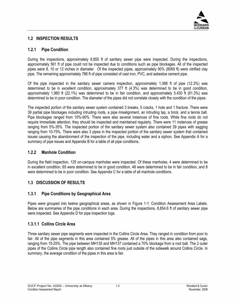
There were 7 inspected sanitary sewer pipes in the North State Quad and Softball Field Area. Six were in poor condition and one was in excellent condition. The pipe in excellent condition was in the very top right corner of the area at the end of the inspected line. Five of the pipes in poor condition contained sags ranging from 30-50%, 5 of these pipes also contained blockages ranging from 20-85%, and 1 of them also contained a circumferential crack. Four of the poor condition pipes had fine roots. Two pipes in this area also had minor grease issues. In summary, excluding the pipe in excellent condition, the pipes in this area on average were in poor condition for multiple reasons including blockage, grease, cracks, and sagging.
SUCF Project No. 01834 – University at Albany 1-8 Woodard & Curran Condition Assessment Report November, 2008
Table 1-6: North State Quad and Softball Field Sanitary Sewer
Historic ID New ID
Start Location
End Location
Start Location
End Location
Page
Num
ber
Crac
ksor
Brea
ks
Bloc
kage
(%)
Grea
se(%
)
Sags
(%)
Fine
Root
s
Cond
ition
MH141 MH142 F10_sMH03 F10_sMH04 50 20 5 45 Poor
MH142 MH144 F10_sMH04 F11_sMH02 55 25 30 Poor
MH145 MH146 F11_sMH03 F11_sMH04 57 Excellent
MH140 MH141 F10_sMH02 F10_sMH03 48 35 30 Y Poor
MH140 MH139 F10_sMH02 F10_sMH01 54 60 5 50 Y Poor
MH144 MH145 F11_sMH02 F11_sMH03 56 Circumferential Crack – 4.2 ft. 30 Y Poor
MH143 MH142 G10_sMH01 F10_sMH04 58 85 Y Poor
1.3.1.6 Parking & Mass Transit Area
There were 4 inspected sanitary sewer pipes in the Parking & Mass Transit Area. They ranged in condition from poor to fair. The one pipe deemed in fair condition was on the verge of being considered in poor condition for both a 25% sag and 30% of the pipe blocked by roots. The other three pipes were all deemed in poor condition due to root blockages in the pipes ranging from 35-80%. Two of the pipes also contained fine roots. In summary, the pipes in this area are on average in poor condition due to root blockages.

SUCF Project No. 01834 – University at Albany 1-9 Woodard & Curran Condition Assessment Report November, 2008
Table 1-7: Parking & Mass Transit Sanitary Sewer
Historic ID New ID
Start Location
End Location
Start Location
End Location Pa
geNu
mbe
rCr
acks
orBr
eaks
Bloc
kage
(%)
Grea
se(%
)
Sags
(%)
Fine
Root
s
Cond
ition
MH60 MH61 H08_sMH02 H08_sMH04 29 70 Poor
MH189 STUB H08_sMH03 Physics 33 30 25 Fair
MH60 MH308 H08_sMH02 H08_sMH01 28 35 Y Poor
MH60 MH189 H08_sMH02 H08_sMH03 31 80 Y Poor
1.3.1.7 Support Building Area
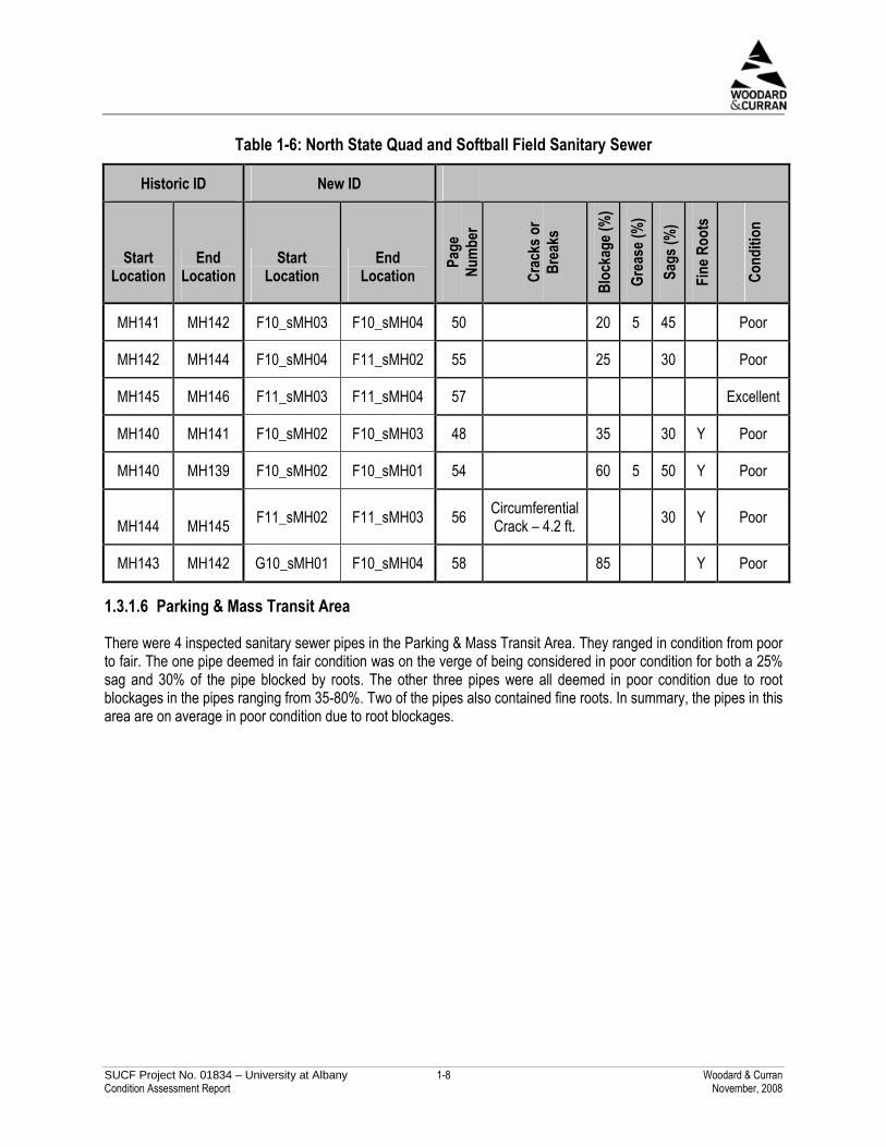
There were 7 sanitary sewer pipes inspected in the Support Building Area. They ranged in condition from poor to excellent. Two of the pipes in poor condition contained root blockages of 75% and 90%. The pipe with the 75% blockage also contained a pipe sag of 25%. The other 2 pipes in poor condition contained pipe sags of 30% and 75%. The pipe with the 30% sag was also 25% blocked. Three pipes in this area also contained fine roots. In summary, half of the pipes were in good condition and half of the pipes were in poor condition. Although the pipes with the worst root problems were grouped at the northeast corner of the area, the rest of the pipes were spread throughout the area independent of condition.
SUCF Project No. 01834 – University at Albany 1-10 Woodard & Curran Condition Assessment Report November, 2008
Table 1-8 Support Building Sanitary Sewer
Historic ID New ID
Start Location
End Location
Start Location
End Location
Page
Num
ber
Crac
ksor
Brea
ks
Bloc
kage
(%)
Grea
se(%
)
Sags
(%)
Fine
Root
s
Cond
ition
MH32 MH27 F05_sMH04 G05_sMH03 25 90 Poor
MH14 MH13 G05_sMH02 F05_sMH03 34 75 Poor
MH14 MH15 G05_sMH02 G05_sMH01 35 Excellent
MH20 MH21 G05_sMH05 G05_sMH06 37 25 30 Poor
MH32 MH29 F05_sMH04 F05_sMH02 26 75 25 Y Poor
MH19 MH20 G04_sMH04 G05_sMH05 36 Y Good
MH20 MH109 G05_sMH05 G05_sMH04 38 Y Good
1.3.1.8 University Field Area
Nine sanitary sewer pipes were inspected in the University Field Area. They ranged in condition from poor to excellent. One of the pipes in fair condition was 30% blocked by roots. Another one of the pipes in fair condition had a 20% sag. One of the pipes in poor condition contained a 35% sag. The other 2 were rated poor for multiple reasons- one was 40% blocked and contained 35% grease, and the other was 30% blocked and had a 60% sag. There were fine roots in four of the nine pipes. In summary, besides the two pipes in excellent condition, the remaining pipes in this area were on average in fair condition, with the pipes in poor condition having multiple issues.

SUCF Project No. 01834 – University at Albany 1-11 Woodard & Curran Condition Assessment Report November, 2008
Table 1-9: University Field Sanitary Sewer
Historic ID New ID
Start Location
End Location
Start Location
End Location
Page
Num
ber
Crac
ksor
Brea
ks
Bloc
kage
(%)
Grea
se(%
)
Sags
(%)
Fine
Root
s
Cond
ition
MH83 MH84 H07_sMH09 I07_sMH03 8 Excellent
MH82 MH310 H07_sMH05 H07_sMH06 20 Excellent
MH81 MH80 I08_sMH04 I08_sMH02 12 20 Fair
MH73 MH74 I07_sMH04 J07_sMH05 24 20 Fair
MH84 MH85 I07_sMH03 I08_sMH01 9 30 Y Fair
MH81 MH63 I08_sMH04 -- 21 Y Good
MH81 MH86 I08_sMH04 J08_sMH01 13 35 Poor
MH82 MH83 H07_sMH05 H07_sMH09 6 40 35 Y Poor
MH85 MH81 I08_sMH01 I08_sMH04 10 30 60 Y Poor
1.3.2 Pipe Condition by Material
Approximately 91.1% of the inspected pipe (8069 ft) was vitrified clay pipe. Of the pipe, approximately 9.9% (802 ft) was in excellent condition, approximately 4.7% (377 ft) was in good condition, approximately 21.9% (1,768 ft) was in fair condition, and approximately 63.5% (5,122 ft) was in poor condition.
Approximately 4.3% of the inspected pipe (377 ft) was cast iron. Of the inspected cast iron pipe, approximately 76.1% (286 ft) was in excellent condition and approximately 23.9% (90 ft) was in fair condition.
Approximately 2.8% of the inspected pipe (252 ft) was asbestos cement. Of the inspected asbestos cement pipe, approximately 40.4% of this pipe (102 ft) was in fair condition, and the remaining 59.6% of the pipe (150 ft) of the pipe was in poor condition.
The remaining 1.8% (158 ft) of inspected pipe was PVC. All of this pipe was in poor condition.
This information is summarized in Figure 1-2, below.

SUCF Project No. 01834 – University at Albany 1-12 Woodard & Curran Condition Assessment Report November, 2008
158
0
150
5,122
0
90
102
1,768
0
0
0
3770
287
0
802
0
1,000
2,000
3,000
4,000
5,000
6,000
7,000
8,000
9,000
Vitrified Clay AsbestosCement
Cast Iron PolyvinylChloride
Material
Pip
eL
eng
th(f
t)
Poor Fair Good Excellent
0 ft Excellent0 ft Good102 ft Fair150 ft Poor
0 ft Excellent0 ft Good0 ft Fair158 ft Poor
287 ft Excellent0 ft Good90 ft Fair0 ft Poor
Figure 1-2: Sanitary Sewer Pipe Material
1.3.3 Manhole Condition
During the visual inspections of manholes, the structural condition, amount of sediment, and hydraulic condition were evaluated for each manhole. Other qualities that were noted about each manhole were the flow volume, flow contents, debris and odor. Each manhole was then assigned an overall condition.
The structural condition assigned to each manhole was either “good,” “damaged functional” or “damaged non-functional.” Damaged functional manholes contained issues with the structure that did not directly affect their ability to function. The damaged non-functional manholes contained structural issues which prevented the manholes from functioning. On average, the inspected manholes were in good structural condition. Only one manhole was determined to be “damaged non-functional.”
The amount of sediment in each manhole was characterized as either “none,” “partial,” “substantial,” or “full.” On average, the manholes were partially full of sediment. Eighteen of the manholes were rated either “substantial” or “full” with respect to sediment. The remaining manholes were determined to be either “none” or “partial” with respect to sediment.
The hydraulic condition of each manhole was assigned similar to the structural condition with the categories of “good,” “damaged functional,” “damaged non-functional,” and “blocked.” Manholes in the blocked category contained blockages that prevented them from functioning hydraulically. The average hydraulic condition of the manholes was good, with only two manholes determined to be “damaged non-functional” or “blocked.”

SUCF Project No. 01834 – University at Albany 1-13 Woodard & Curran Condition Assessment Report November, 2008
An overall condition was assigned to each manhole in the categories of “excellent,” “good,” “fair” or “poor.” The average condition of the inspected manholes was good.
Table 1-10, below, contains a summary of how many of the inspected structures were rated in the individual categories, as well as overall condition.
Table 1-10: Condition of Manholes
Structural Condition Sediment Hydraulic Condition Overall Condition
Good 85 None 25 Good 90 Excellent 5 Damaged Functional 40 Partial 85
Damaged Functional 34 Good 65
Damaged Non-Functional 1 Substantial 15
Damaged Non-Functional 1 Fair 48
Full 1 Blocked 1 Poor 8
The individual inspection results for each manhole can be found in the Sanitary Sewer Manholes Table in Appendix C. The top section of this table includes the sanitary sewer manholes that were rated “fair” or “poor” in overall condition, had signs of damage which appeared to be affecting the functionality of the manhole, had substantial sediment accumulation, or that had a combination of these issues. The second half of the table includes the remaining inspected manholes. The table is ordered by manhole condition, with the manhole in poorest condition first and ending with the manhole in the best condition.
1.3.4 Capacity Assessment Results
For the Capacity Assessment, flow metering was conducted to gather information on pipe flow in four different locations on campus. Location 1 was at MH145 between the northeast softball field and Washington Avenue, and was chosen to characterize the flow at the end of the northern interceptor. Location 2 was at MH103, on the north side of Justice Drive between the University Police Building and University Drive East, and was chosen to characterize the flow at the end of the southern interceptor. Location 3 was at MH86 which is just south of Building 1 in the Indian Quad, and was chosen to characterize the flow contributions upstream of the end of the southern interceptor. Location 4 was at MH46 near Building 15 at the southwest corner of the Dutch Quad and was chosen to characterize the flow contributions at a further upstream location of the southern interceptor. Precipitation was also measured during the period of time that the flow metering took place, because if the precipitation and flows within the system are correlated with each other, this indicates inflow and infiltration. Data was collected between May 16, 2007 and June 14, 2007, and then was analyzed.
One of the results of the analysis was that there was minimal correlation between precipitation and flow, which indicates that there is little infiltration or inflow into pipes. The results also indicated that there were some blockages in the pipes blocking pipe flows. In particular, data indicated that there were blockages in pipes downstream from Location 4, MH46. It also indicated that at each of the four locations there were many instances where there was water in the pipe when there was no flow. This standing water indicates that there may be blockages or sags in the pipes around each of the monitoring locations.

SUCF Project No. 01834 – University at Albany 2-1 Woodard & Curran Condition Assessment Report November, 2008
2. STORM SEWER SYSTEM
2.1 METHOD
2.1.1 Pipe Inspections
Camera inspections of selected storm sewer pipes were conducted to determine their physical condition. The pipe inspections began on August 1, 2007 and were completed on August 20, 2007 by Savin Engineers, PC, of Pleasantville, New York. An additional segment of storm sewer was inspected by Lash Contracting, Inc. of Latham, New York on August 12, 2008. This inspection was completed in response to a sinkhole located in the hammer-throw area, near the baseball field in the southeastern portion of campus.
A pan-and-tilt color camera was used to conduct the inspections, which allows the operator to rotate, raise and lower the camera head to provide the optimum view of the interior of the pipes. The camera was stopped at each service connection and lateral, and rotated to allow the inspection of the interior of each connection. All video was recorded in MPEG-1 format and stored directly on labeled DVDs. The log information for each pipe segment included street location, manhole and catch basin numbers, pipe size, pipe material, line items for each comment and defect, and a schematic diagram of the manhole-to-manhole observations. The defects that were noted included broken pipe, cracks, offset joints, root intrusions, grease accumulation, infiltration, pipe obstructions, and catch basin covers that could not be opened.
The following areas of the storm sewer system were inspected: the pipes in the courtyard north of the Business Building that continue north along the Colonial Quad, the pipes to the west of the Social Sciences Building, the pipes just south of the Humanities and Education Buildings, pipes surrounding the Support Buildings, pipes south of University Field, pipes south and west of Dutch Quad, pipes north of the Fine Arts Building, pipes west of State Quad, and pipes between the baseball field and University Drive East. For a full list of inspected pipes, see Appendix A. The following report is an analysis of the results of the sanitary and storm sewer camera pipe inspections.
After pipe inspection, each pipe was assigned a condition. The four conditions that pipes were divided up into are: excellent, good, fair and poor. These conditions were assigned based on the following five criteria: whether a pipe had cracks/breaks, pipe blockages, grease, sags or fine roots. In order for a pipe to be considered in excellent condition, it could not contain cracks, pipe blockages, grease, pipe sags, or fine roots. In order for a pipe to be considered in good condition, it could contain a pipe blockage up to 5%, a pipe sag up to 5%, and fine roots. For a pipe to be considered in fair condition, it could contain pipe blockages up to 30%, grease up to 10%, and pipe sags up to 25%. Any pipe with cracks, breaks, pipe blockages of 30% or greater, grease greater than 10%, or pipe sags of 25% or greater were considered poor. Table 2-1 below details each condition:

SUCF Project No. 01834 – University at Albany 2-2 Woodard & Curran Condition Assessment Report November, 2008
Table 2-1: Pipe Condition Determination Criteria
Condition Evaluation Determination Criteria
Excellent
No cracks or breaks No pipe blockages No grease No pipe sags No fine roots
Good
No cracks or breaks May contain pipe blockages up to 5% No grease May contain pipe sags up to 5% May contain fine roots
Fair
No cracks or breaks May contain pipe blockages up to 30% May contain grease up to 10% May contain pipe sags up to 25% May contain fine roots
Poor
May contain cracks or breaks May contain pipe blockages greater than 30% May contain grease greater than 10% May contain pipe sags greater than 25% May contain fine roots
This report represents items developed based on our observations as part of this project. The actual condition and capacity of pipes may have changed since the time of our investigations.
2.1.2 Visual Inspections
The visual inspections of the condition of catch basins, drainage manholes, drain inlets and other storm sewer appurtenances were conducted between June 12, 2007 and August 14, 2007 by Woodard & Curran. The structural condition, amount of sediment and hydraulic condition were evaluated for each of these storm sewer features. Other qualities that were noted about each of these storm sewer features were the flow volume, flow contents, debris and odor. Each feature was then assigned an overall condition of “excellent,” “good,” “fair,” or “poor” during the visual inspection.
This report represents items developed based on our observations as part of this project. The actual condition and capacity of the storm sewer features may have changed since the time of our investigations.

SUCF Project No. 01834 – University at Albany 2-3 Woodard & Curran Condition Assessment Report November, 2008
2.2 INSPECTION RESULTS
2.2.1 Pipe Condition
During the storm sewer pipe inspections, approximately 9,231 ft of pipe were inspected, 8,642 ft by Savin Engineers, P.C. and 589 ft by Lash Contracting. Approximately 225 ft of pipe could not be inspected due to conditions such as pipe blockages. Over 95% of the inspected pipes were 15, 18, 21, 30 or 36 inches in diameter. The remaining pipes were 8, 10, 12 or 27 inches in diameter. Over 98% (9,100 ft) of the inspected pipes were reinforced concrete pipe. The remaining approximately 131 ft of pipe consisted of asbestos cement and PVC pipe.
Of the pipe inspected in the storm sewer camera inspection, approximately 4,026 ft of pipe (43.6%) was determined to be in excellent condition, approximately 743 ft (8.0%) was determined to be in good condition, approximately 2,127 ft (23.0%) was determined to be in fair condition, and approximately 2,335 ft (25.2%) was determined to be in poor condition. The diameter of the pipes did not correlate closely with the condition of the pipes.
The inspected portion of the storm sewer system pipes contained a circumferential crack, a circumferential fracture, multiple infiltration drippers, multiple infiltration runners, 22 longitudinal cracks, and 3 locations with multiple cracks. There were 60 partial blockages ranging from 5% to 45%. These blockages included deposits, obstacles, and a pipe misalignment. There were also several instances of fine roots. While fine roots do not require immediate attention, they should be inspected and maintained regularly. There were 2 pipe sags in the inspected pipes of 15% and 20%. There were 2 pipes in the inspected portion of the storm sewer system which could not be inspected due to catch basin covers which could be opened.
2.2.2 Catch Basin, Drainage Manhole, Drain Inlet, Storm Sewer Appurtenance Conditions
During the field inspection, 519 on-campus catch basins were inspected. Of these catch basins, 3 were determined to be in excellent condition, 226 were determined to be in good condition, 232 were determined to be in fair condition, and 58 were determined to be in poor condition. There were also 123 on-campus drainage manholes inspected. Of these drainage manholes, 4 were determined to be in excellent condition, 67 were determined to be in good condition, 46 were determined to be in fair condition, and 6 were determined to be in poor condition. There were also 298 drain inlets inspected. Of these drain inlets, 1 was in determined to be in excellent condition, 157 were determined to be in good condition, 78 were determined to be in fair condition, and 62 were determined to be in poor condition. There were 34 other sewer system appurtenances inspected. Of these features, 7 were determined to be in excellent condition, 22 in good condition, 4 in fair condition and 1 in poor condition.
2.3 DISCUSSION OF RESULTS
2.3.1 Pipe Condition by Geographical Area
Pipes were grouped into 9 geographical areas, as shown in Figure 1-1. Below are summaries of the pipe conditions in each area.
2.3.1.1 Business Building Area
Six storm sewer pipes were inspected in the Business Building Area. They ranged in condition from good to excellent. The 4 pipes in good condition contained fine roots. In summary, the pipes in this area were in good condition on average.

SUCF Project No. 01834 – University at Albany 2-4 Woodard & Curran Condition Assessment Report November, 2008
Table 2-2: Business Building Storm Sewer
Historic ID New ID
Start Location
End Location
Start Location
End Location
Page
Num
ber
Crac
ksor
Brea
ks
Bloc
kage
(%)
Grea
se(%
)
Sags
(%)
Fine
Root
s
Cond
ition
CB223 CB222 F08_dCB06 F08_dCB07 126 Y Good
CB223 CB224 F08_dCB06 F08_dCB05 127 Excellent
CB226 CB224 F08_dCB04 F08_dCB05 128 Y Good
CB226 CB220 F08_dCB04 F08_dCB03 129 Y Good
CB203 CB220 E08_dCB14 F08_dCB03 130 Y Good
CB203 MH169 E08_dCB14 E08_dMH05 131 Excellent
2.3.1.2 Colonial Quad Area
There was 1 inspected storm sewer pipe in the storm sewer system of the Colonial Quad area. It was deemed to be in good condition because it contained no issues other than fine roots.
Table 2-3: Colonial Quad Storm Sewer
Historic ID New ID
Start Location
End Location
Start Location
End Location
Page
Num
ber
Crac
ksor
Brea
ksBl
ocka
ge(%
)
Grea
se(%
)
Sags
(%)
Fine
Root
s
Cond
ition
MH169 MH168 E08_dMH05 E08_dMH06 132 Y Good
2.3.1.3 Dutch Quad Area
Seven storm sewer pipes were inspected in the Dutch Quad Area. A portion of them were in poor condition, and the rest were in excellent condition. One of the pipes that was determined to be in poor condition contained an infiltration dripper near the southeastern corner of the Dutch Quad, below the UKids daycare playground, in the same area where there were cracks in the inspected portion of the sanitary system. The other 2 pipes considered to be in poor condition were located between the Dutch Purple lot and Building 16. One contained an infiltration runner (underneath a sidewalk) and the other contained deposits which filled 35% of its cross-sectional area. In summary, over half of the pipes in this area were in excellent shape, and the other pipes were in poor condition.

SUCF Project No. 01834 – University at Albany 2-5 Woodard & Curran Condition Assessment Report November, 2008
Table 2-4: Dutch Quad Storm Sewer
Historic ID New ID
Start Location
End Location
Start Location
End Location
Page
Num
ber
Cracks or Breaks
Bloc
kage
(%)
Grea
se(%
)
Sags
(%)
Fine
Root
s
Cond
ition
MH194 MH52 F07_dMH02 F06_dMH05 73 35 Poor
MH52 MH51 F06_dMH05 G06_dMH01 75 Excellent
MH51 MH49 G06_dMH01 G06_dMH04 76 Infiltration
Runner [1/2 GPM] – 10.4 ft.
Poor
MH45 MH47 G06_dMH03 G06_dMH02 101 Excellent
MH47 MH49 G06_dMH02 G06_dMH04 102 Excellent
MH45 MH44 G06_dMH03 H06_dMH01 103 Excellent
MH44 MH43 H06_dMH01 H07_dMH02 104 Infiltration
Dripper [1/32 GPM] – 123.4 ft.
Poor
2.3.1.4 Humanities and Education Area
Seven storm sewer pipes were inspected in the Humanities and Education Area. They ranged in condition from poor to excellent condition. The 2 pipes deemed to be in poor condition each had 3 longitudinal cracks, and minor blockages. The pipe in fair condition contained a 20% sag. The pipe deemed to be in good condition contained fine roots. In summary, besides the 2 pipes in this area in poor condition due to cracking, the pipes were in excellent or good condition.

SUCF Project No. 01834 – University at Albany 2-6 Woodard & Curran Condition Assessment Report November, 2008
Table 2-5: Humanities and Education Sanitary Sewer
Historic ID New ID
Start Location
End Location
Start Location
End Location
Page
Num
ber
Crac
ksor
Brea
ks
Bloc
kage
(%)
Grea
se(%
)
Sags
(%)
Fine
Root
s
Cond
ition
MH155 CB165 G07_dMH04 G07_dCB08 77 Excellent
MH155 MH182 G07_dMH04 G07_dMH06 Longitudinal Crack – 20.3 ft.
MH182 MH181 G07_dMH06 G08_dMH01 Longitudinal Crack – 30.1 ft.
MH181 MH316 G08_dMH01 G08_dMH02
78
Longitudinal Crack – 43.0 ft.
10 Poor
MH316 CB77 G08_dMH02 G07_dCB11 Longitudinal Crack – 90.8 ft.
CB77 MH58 G07_dCB11 H07_dMH05 Longitudinal Crack – 156.7 ft.
MH58 CB79 H07_dMH05 H07_dCB05
79
Longitudinal Crack – 194.0 ft.
5 Y Poor
2.3.1.5 South State Quad and Fine Arts Area
There were 5 storm sewer pipes inspected in the South State Quad and Fine Arts Area. They ranged in condition from poor to excellent. The pipe in poor condition contained a circumferential crack and the pipe was 20% blocked. The pipes in fair condition all contained blockages of 15-25%. In summary, besides the pipe in excellent condition and the circumferential fracture in 1 pipe, the pipes on average in this area were in fair condition due to pipe blockages.

SUCF Project No. 01834 – University at Albany 2-7 Woodard & Curran Condition Assessment Report November, 2008
Table 2-6: South State Quad and Softball Field Storm Sewer
Historic ID New ID
Start Location
End Location
Start Location
End Location
Page
Num
ber
Crac
ksor
Brea
ks
Bloc
kage
(%)
Grea
se(%
)
Sags
(%)
Fine
Root
s
Cond
ition
CB232 MH172 G09_dCB07 F09_dMH01 123 Circumferential Crack – 94.0 ft. 20 Poor
CB231 CB229 G09_dCB06 G09_dCB05 124 20 Fair
CB231 CB232 G09_dCB06 G09_dCB07 125 Excellent
CB228 CB227 G09_dCB01 F09_dCB23 133 15 Fair
CB228 CB229 G09_dCB01 G09_dCB05 134 25 Fair
2.3.1.6 Social Sciences Area
Eleven storm sewer pipes were inspected in the Social Sciences Area. The pipes ranged in condition from fair to excellent condition. The 4 in fair condition contained pipe blockages ranging from 10-25%. These pipes were all located either parallel to, or underneath the sidewalk that exits the Social Sciences building and leads to the Podium West Lot and the Colonial Gold Lot-C. In summary, besides the pipes next to the sidewalk which could use some cleaning, the pipes in this area were in excellent condition.

SUCF Project No. 01834 – University at Albany 2-8 Woodard & Curran Condition Assessment Report November, 2008
Table 2-7: Social Sciences Storm Sewer
Historic ID New ID
Start Location
End Location
Start Location
End Location
Page
Num
ber
Crac
ksor
Brea
ksBl
ocka
ge(%
)
Grea
se(%
)
Sags
(%)
Fine
Root
s
Cond
ition
CB162 MH156 F07_dCB10 F07_dMH04 65 Excellent
CB162 CB164 F07_dCB10 F07_dCB09 66 20 Fair
MH154 CB90 F07_dMH03 F07_dCB04 68 Excellent
MH154 MH153 F07_dMH03 F07_dMH01 69 Excellent
MH153 3101 F07_dMH01 F07_dCB01 70 Excellent
3101 CB505 F07_dCB01 F07_dCB03 71 Excellent
CB505 MH194 F07_dCB03 F07_dMH02 72 Excellent
CB91 CB164 F07_dCB05 F07_dCB09 119 10 Fair
CB91 CB90 F07_dCB05 F07_dCB04 120 Excellent
CB93 CB161 F07_dCB06 F07_dCB07 121 15 Fair
CB93 CB90 F07_dCB06 F07_dCB04 122 25 Fair
2.3.1.7 Support Building Area
There were 27 storm sewer pipes inspected in the Support Building Area. These pipes ranged in condition from poor to excellent, with 1 pipe whose condition could not be determined. The pipe whose condition could not be determined had catch basins which could not be opened. Four of the pipes in poor condition contained cracks, and 3 also contained blockages of 10-15%. Three of these pipes were in one pipe length stretching from the Support Building A parking lot down to the southwest corner of the Power Plant. The pipes in poor condition without cracks were blocked 40-45% with muck and deposits. Thirteen of the 14 pipes in fair condition were 10-25% blocked with deposits. The other pipe in fair condition had a 15% sag, the only pipe sag in this area. Four of the pipes in this area contained fine roots. In summary, besides the pipes in excellent condition, and the pipe length running along the west side of the Power Plant which contained many cracks, the pipes in this area were on average in fair condition due to a build-up of deposits.

SUCF Project No. 01834 – University at Albany 2-9 Woodard & Curran Condition Assessment Report November, 2008
Table 2-8: Support Building Storm Sewer
Historic ID New ID
Start Location
End Location
Start Location
End Location
Page
Num
ber
Crac
ksor
Brea
ks
Bloc
kage
(%)
Grea
se(%
)
Sags
(%)
Fine
Root
s
Cond
ition
MH30 CB50 F05_dMH02 F05_dCB14 86 Excellent MH9 CB14 G05_dMH04 G05_dCB12 90 Excellent MH5 MH4 G04_dMH02 G05_dMH01 96 Excellent CB10 MH4 G05_dCB05 G05_dMH01 111 Excellent MH31 MH28 F05_dMH04 G05_dMH06 84 20 Fair MH9 MH8 G05_dMH04 G05_dMH05 91 20 Fair MH8 CB16 G05_dMH05 G05_dCB13 92 15 Fair
MH8 MH6 G05_dMH05 G05_dMH03 93 10 Fair MH6 MH4 G05_dMH03 G05_dMH01 94 15 Fair MH8 MH10 G05_dMH05 G05_dMH07 95 15 Fair CB4 CB5 F05_dCB10 F05_dCB11 99 25 Fair CB6 CB3 G05_dCB01 F05_dCB12 105 15 Fair CB6 CB9 G05_dCB01 G05_dCB03 106 15 Y Fair CB8 CB8A G05_dCB04 -- 107 15 Fair
CB10 CB9 G05_dCB05 G05_dCB03 110 10 Y Fair MH3 1012 F05_dMH03 G05_dCB06 113 10 Fair CB15 CB16 G05_dCB14 G05_dCB13 114 10 Fair MH28 CB46 G05_dMH06 F05_dCB17 115 10 Fair CB51 CB49 F05_dCB13 F05_dCB09 118 20 Fair MH7 MH6 G05_dMH02 G05_dMH03 112 5 Good
Longitudinal Crack – 90.0 ft.
Longitudinal Crack – 114.4 ft. MH31 MH49A F05_dMH04 -- 85
Longitudinal Crack – 118.5 ft.
Poor

SUCF Project No. 01834 – University at Albany 2-10 Woodard & Curran Condition Assessment Report November, 2008
Historic ID New ID
Start Location
End Location
Start Location
End Location
Page
Num
ber
Crac
ksor
Brea
ks
Bloc
kage
(%)
Grea
se(%
)
Sags
(%)
Fine
Root
s
Cond
ition
Longitudinal Crack – 7.0 ft.
Circumferential Crack – 20.2 ft.
Longitudinal Crack – 28.6 ft.
Longitudinal Crack – 44.6 ft.
Multiple Cracks – 57.9 ft.
Multiple Cracks – 64.7 ft.
Longitudinal Crack – 69.7 ft.
MH30 CB557 F05_dMH02 F05_dCB15 87
Longitudinal Crack – 74.5 ft.
15 Poor
Longitudinal Crack – 4.7 ft.
Longitudinal Crack – 20.9 ft. CB557 MH3 F05_dCB15 F05_dMH03 88
Longitudinal Crack – 36.8 ft.
10 Poor
Longitudinal Crack – 41.9 ft.
Longitudinal Crack – 98.0 ft. MH3 MH4 F05_dMH03 G05_dMH01 89
Longitudinal Crack – 160.3 ft.
10 Poor
MH1 CB4 F05_dMH01 F05_dCB10 97 40 Y Poor

SUCF Project No. 01834 – University at Albany 2-11 Woodard & Curran Condition Assessment Report November, 2008
Historic ID New ID
Start Location
End Location
Start Location
End Location
Page
Num
ber
Crac
ksor
Brea
ks
Bloc
kage
(%)
Grea
se(%
)
Sags
(%)
Fine
Root
s
Cond
ition
CB7 CB9 G05_dCB02 G05_dCB03 108 Can’t open CBs
Unde-termined
CB51 CB52 F05_dCB13 F05_dCB16 116 45 Y Poor
2.3.1.8 University Field Area
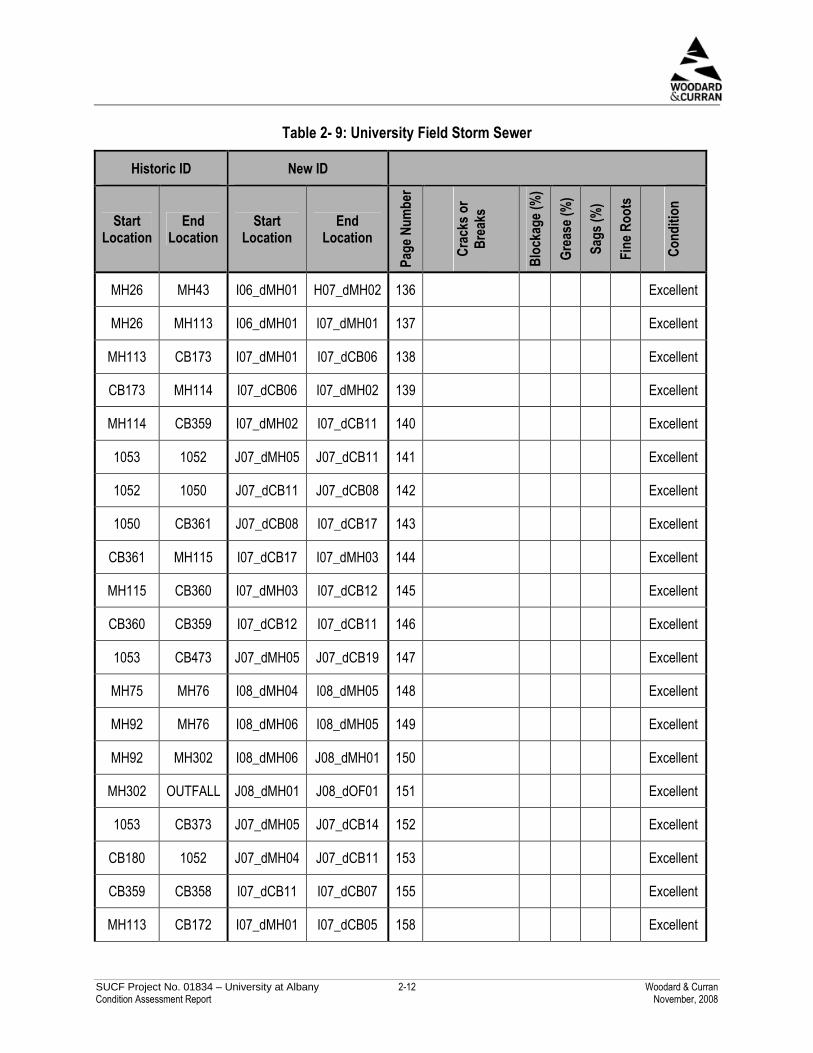
There were 24 storm sewer pipes inspected in the University Field Area. Twenty of the pipes were deemed in excellent condition, 1 was deemed in good condition, and 2 were deemed in poor condition. The pipe in the worst condition is located near the northeast corner of the Physical Education building. This pipe contained 2 longitudinal cracks and was also 45% blocked. The other pipe in poor condition was located at the southwest corner of the University Field and was 35% blocked by gravel. There were fine roots in 1 pipe. The rest of the pipes were in excellent shape. In summary, besides the 2 pipes in poor condition, the average condition of the pipe in this area was excellent.
SUCF Project No. 01834 – University at Albany 2-12 Woodard & Curran Condition Assessment Report November, 2008
Table 2- 9: University Field Storm Sewer
Historic ID New ID
Start Location
End Location
Start Location
End Location
Page
Num
ber
Crac
ksor
Brea
ks
Bloc
kage
(%)
Grea
se(%
)
Sags
(%)
Fine
Root
s
Cond
ition
MH26 MH43 I06_dMH01 H07_dMH02 136 Excellent
MH26 MH113 I06_dMH01 I07_dMH01 137 Excellent
MH113 CB173 I07_dMH01 I07_dCB06 138 Excellent
CB173 MH114 I07_dCB06 I07_dMH02 139 Excellent
MH114 CB359 I07_dMH02 I07_dCB11 140 Excellent
1053 1052 J07_dMH05 J07_dCB11 141 Excellent
1052 1050 J07_dCB11 J07_dCB08 142 Excellent
1050 CB361 J07_dCB08 I07_dCB17 143 Excellent
CB361 MH115 I07_dCB17 I07_dMH03 144 Excellent
MH115 CB360 I07_dMH03 I07_dCB12 145 Excellent
CB360 CB359 I07_dCB12 I07_dCB11 146 Excellent
1053 CB473 J07_dMH05 J07_dCB19 147 Excellent
MH75 MH76 I08_dMH04 I08_dMH05 148 Excellent
MH92 MH76 I08_dMH06 I08_dMH05 149 Excellent
MH92 MH302 I08_dMH06 J08_dMH01 150 Excellent
MH302 OUTFALL J08_dMH01 J08_dOF01 151 Excellent
1053 CB373 J07_dMH05 J07_dCB14 152 Excellent
CB180 1052 J07_dMH04 J07_dCB11 153 Excellent
CB359 CB358 I07_dCB11 I07_dCB07 155 Excellent
MH113 CB172 I07_dMH01 I07_dCB05 158 Excellent

SUCF Project No. 01834 – University at Albany 2-13 Woodard & Curran Condition Assessment Report November, 2008
Historic ID New ID
Start Location
End Location
Start Location
End Location
Page
Num
ber
Crac
ksor
Brea
ks
Bloc
kage
(%)
Grea
se(%
)
Sags
(%)
Fine
Root
s
Cond
ition
MH26 CB45 I06_dMH01 I06_dCB05 135 Y Good
Longitudinal Crack – 16.5 ft.
CB361 CB374 I07_dCB17 J07_dCB06 154 Longitudinal
Crack – 19.8 ft.
45 Poor
MH113 CB362 I07_dMH01 I07_dCB01 156 35 Poor

SUCF Project No. 01834 – University at Albany 2-14 Woodard & Curran Condition Assessment Report November, 2008
2.3.1.9 Hammer Throw Area
There were 2 storm sewer pipes inspected in the Hammer Throw Area. These two pipes were inspected by Lash Contracting, Inc. One pipe was deemed to be in fair condition and the other deemed to be in poor condition. Each of these pipes had multiple infiltration drippers and runners, typically in the vicinity of pipe joints, and multiple instances of attached encrustation deposits. The second of the two pipes also had blockages of up to 30% and multiple cracks.
Table 2- 10: Hammer Throw Storm Sewer
Historic ID New ID
Start Location
End Location
Start Location
End Location
Page
Num
ber
Crac
ksor
Brea
ks
Bloc
kage
(%)
Grea
se(%
)
Sags
(%)
Fine
Root
s
Cond
ition
MH97 MH96 L08_dMH02 L08_dMH03 Multiple
Infiltration Drippers and
Runners 10 Fair
MH97 CB128 L08_dMH02 M07_dCB12
Multiple Cracks; Multiple
Infiltration Drippers and
Runners
30 Poor
2.3.2 Pipe Condition by Material Pipe Condition by Material
Pipe condition was analyzed by pipe material. Below are summaries of the pipe conditions of pipes of different materials.
Approximately 98.6% of the inspected pipe (9,100 ft) was reinforced concrete pipe. Of this pipe, approximately 43.9% (3,996 ft) was in excellent condition, 8.2% (743 ft) was in good condition, 23.4% (2,127 ft) was in fair condition, and 24.6% (2,335 ft) was in poor condition.
Approximately 1.2% of the inspected pipe (100 ft) was asbestos cement. Of the asbestos cement pipe, 100% (100 ft) was in poor condition.
The remaining 0.4% (31 ft) of inspected pipe was PVC. All of this pipe was in excellent condition.
This information is summarized in Figure 2-1, below

SUCF Project No. 01834 – University at Albany 2-15 Woodard & Curran Condition Assessment Report November, 2008
0
2,235
1000 02,127
0
743
031
3,996
0
0
1,000
2,000
3,000
4,000
5,000
6,000
7,000
8,000
9,000
10,000
ReinforcedConcrete
AsbestosCement
PolyvinylChloride
Material
Pip
eL
eng
th(f
t)
Poor Fair Good Excellent
0 ft Excellent0 ft Good0 ft Fair100 ft Poor
31 ft Excellent0 ft Good0 ft Fair0 ft Poor
Figure 2-1: Storm Sewer Pipe Material
2.4 CATCH BASIN, DRAINAGE MANHOLE, DRAIN INLET, STORM SEWER APPURTENANCE CONDITIONS
During the visual inspections of manholes, the structural condition, amount of sediment, and hydraulic condition were evaluated for each catch basin, drainage manhole, drain inlet and storm sewer appurtenance. Other qualities that were noted about each storm sewer feature were the flow volume, flow contents, debris and odor. Each storm sewer feature was then assigned an overall condition.
The structural condition assigned to each storm sewer feature was either “good,” “damaged functional” or “damaged non-functional.” Damaged functional manholes contained issues with the structure that did not directly affect their ability to function. The damaged non-functional manholes contained structural issues which prevented the storm sewer features from functioning. On average, the inspected catch basins, drainage manholes, drain inlets and other appurtenances were in good condition.
The amount of sediment in each manhole was characterized as either “none,” “partial,” “substantial,” or “full.” On average, the manholes were partially full of sediment. Eighteen of the manholes were rated either “substantial” or “full” with respect to sediment. The remaining manholes were determined to be either “none” or “partial” with respect to sediment. On average, the catch basins, drainage manholes and drain inlets were partially full of sediment. Most of the appurtenances had no sediment accumulation. The hydraulic condition of each storm sewer feature was assigned similar to the structural condition with the categories of “good,” “damaged functional,” “damaged non-functional,” and also “blocked” and “surcharging”. Storm sewer features in the blocked category contained blockages that prevented them from functioning hydraulically. Features in the surcharging category exhibited water exiting the grates because the feature was so full of water. The

SUCF Project No. 01834 – University at Albany 2-16 Woodard & Curran Condition Assessment Report November, 2008
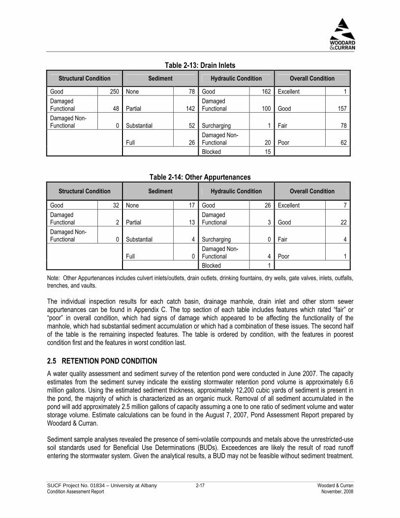
average hydraulic condition of the catch basins was damaged functional, with twenty catch basins that were either surcharging, damaged non-functional or blocked. The hydraulic condition of the drainage manholes was split almost evenly between good and damaged functional. The average condition of the drain inlets was good, with thirty-three of the drain inlets that were either surcharging, damaged non-functional or blocked. The other appurtenances were on average in good hydraulic condition. An overall condition was assigned to each storm sewer feature in the categories of “excellent,” “good,” “fair” or “poor.” The average condition of the inspected catch basins was fair, with 58 catch basins in poor condition. The average condition of the inspected drainage manholes was good. The average condition of the inspected drain inlets was good, although 62 were noted in poor condition. The other appurtenances were on average in good condition. Tables 2-11 through 2-14 below, contain summaries of how many of the inspected structures were rated in the individual categories, as well as overall condition.
Table 2-11: Catch Basins Structural Condition Sediment Hydraulic Condition Overall Condition
Good 391 None 52 Good 190 Excellent 3 Damaged Functional 123 Partial 281
Damaged Functional 310 Good 226
Damaged Non-Functional 5 Substantial 162 Surcharging 2 Fair 232
Full 21 Damaged Non-Functional 8 Poor 58 Blocked 9
Table 2-12: Drainage Manholes Structural Condition Sediment Hydraulic Condition Overall Condition
Good 91 None 16 Good 62 Excellent 4 Damaged Functional 32 Partial 87
Damaged Functional 61 Good 67
Damaged Non-Functional 0 Substantial 19 Surcharging 0 Fair 46
Full 1 Damaged Non-Functional 0 Poor 6 Blocked 0
SUCF Project No. 01834 – University at Albany 2-17 Woodard & Curran Condition Assessment Report November, 2008
Table 2-13: Drain Inlets Structural Condition Sediment Hydraulic Condition Overall Condition
Good 250 None 78 Good 162 Excellent 1 Damaged Functional 48 Partial 142
Damaged Functional 100 Good 157
Damaged Non-Functional 0 Substantial 52 Surcharging 1 Fair 78
Full 26 Damaged Non-Functional 20 Poor 62 Blocked 15
Table 2-14: Other Appurtenances Structural Condition Sediment Hydraulic Condition Overall Condition
Good 32 None 17 Good 26 Excellent 7 Damaged Functional 2 Partial 13
Damaged Functional 3 Good 22
Damaged Non-Functional 0 Substantial 4 Surcharging 0 Fair 4
Full 0 Damaged Non-Functional 4 Poor 1 Blocked 1
Note: Other Appurtenances includes culvert inlets/outlets, drain outlets, drinking fountains, dry wells, gate valves, inlets, outfalls, trenches, and vaults.
The individual inspection results for each catch basin, drainage manhole, drain inlet and other storm sewer appurtenances can be found in Appendix C. The top section of each table includes features which rated “fair” or “poor” in overall condition, which had signs of damage which appeared to be affecting the functionality of the manhole, which had substantial sediment accumulation or which had a combination of these issues. The second half of the table is the remaining inspected features. The table is ordered by condition, with the features in poorest condition first and the features in worst condition last.
2.5 RETENTION POND CONDITION A water quality assessment and sediment survey of the retention pond were conducted in June 2007. The capacity estimates from the sediment survey indicate the existing stormwater retention pond volume is approximately 6.6 million gallons. Using the estimated sediment thickness, approximately 12,200 cubic yards of sediment is present in the pond, the majority of which is characterized as an organic muck. Removal of all sediment accumulated in the pond will add approximately 2.5 million gallons of capacity assuming a one to one ratio of sediment volume and water storage volume. Estimate calculations can be found in the August 7, 2007, Pond Assessment Report prepared by Woodard & Curran.
Sediment sample analyses revealed the presence of semi-volatile compounds and metals above the unrestricted-use soil standards used for Beneficial Use Determinations (BUDs). Exceedences are likely the result of road runoff entering the stormwater system. Given the analytical results, a BUD may not be feasible without sediment treatment.

SUCF Project No. 01834 – University at Albany 2-18 Woodard & Curran Condition Assessment Report November, 2008
Water quality and sediment exceedances can be found in the August 7, 2007, Pond Assessment Report, Tables 2-1 and 3-1.

SUCF Project No. 01834 – University at Albany 3-1 Woodard & Curran Condition Assessment Report November, 2008
3. WATER SYSTEM
3.1 METHOD
3.1.1 Water Tower Inspections
Woodard & Curran reviewed the water tower inspection reports developed by Schafer Engineering Associates (SEA) and KTA-Tator Engineering Services. The results from these reports were summarized and are reported below in the ‘Results’ and ‘Discussion of Results’ sections. No other inspections of the water tower were conducted by Woodard & Curran.
The SEA visual inspection of the water tower was conducted on October 31 and November 1, 2005. Three technicians rappelled down the face of the water tower and visually inspected the structure, documenting their findings in digital photos and video. Measurements of the tower were taken to cross reference with current CAD drawings. The water tower’s exterior surface and the bell tower frame were inspected. During inspection, an electric rotary grinder was used to determine the extent of the corrosion near the ground level of the water tower.
The KTA-Tator Engineering Services inspection was conducted on May 31, 2006, and focused on the exterior and interior coatings of the water tower tank. As part of this inspection, there was a visual inspection of the corrosion (amount and location) on the tank, the coating thickness of the inside and outside of the tank were measured with a Positector 6000 – F1, a Tooke Gage Mark IV was used to detect how many coatings there were and to estimate their corresponding thicknesses, the adhesion was measured with the ASTM D3359 adhesion test, the substrate condition was measured by removing a section of coating to look for under-film corrosion and mill scale, an ultrasonic thickness gage was used to measure the plate thickness, a visual inspection for safety, operations, and structural conditions was completed, and photographs were taken.
The analysis below was developed based on the water tower inspection reports. The actual condition and capacity of the water tower may have changed since the time of the above investigations.
3.1.2 Distribution System Investigations
During the course of our investigations, we had various conversations with University staff related to the water distribution system. Fire flow testing at selected fire hydrants was conducted by Woodard & Curran and University at Albany staff on March 27, 2008. Additionally, industry references were consulted to provide supplemental information related to system condition.
This report represents items developed based on the above observations. The actual condition and capacity of the distribution system infrastructure items may have changed since the time of our investigations.
3.2 INSPECTION RESULTS
3.2.1 Water Tower Inspection Results
The following results section is a summary of the results sections from the SEA and OGS reports. These two reports can be referenced for more detail. Woodard & Curran is not aware of any changes in the condition of the water tower since these two reports.

SUCF Project No. 01834 – University at Albany 3-2 Woodard & Curran Condition Assessment Report November, 2008
The water tower was designed and constructed in 1964, and supports both the water tank and the bell tower. The water tower is made primarily of steel panels ranging in thickness from 3/8” to 3/4". Below are the assessments of the water tower’s structure, and the exterior and interior coatings based on the SEA and OGS inspections.
• Structure of Water Tower: o The structure of the water tower was deemed to be in good condition overall.
o The exposed part of the water tower foundation was deemed in good condition.
o The cables, a structural component of the tower, had variable tension.
o There was surface corrosion and pitting on welds and several structural elements such as gusset plates, braces, triangle stiffener plates, flange plates, tube braces, framed connections, cable braces, turnbuckles and radial beams.
o There was corrosion on exterior non-structural features of the tank, such as hatches, vent pipes, speaker attachments, conduit, and grating.
o The vertical ribs were bent clockwise, as much as four inches over three feet where the ‘I’ shaped beams meet the ‘T’ shaped beams.
• Exterior Coating of Water Tower: o The exterior water tower face up to the top of the water tank was deemed to be in good
condition.
o The coatings on the exterior of the tank roof were deemed to be in fair condition given localized corrosion on 10% of roof.
o Tank shell coatings were deemed to be in good condition.
o The tank’s exterior stiffener ribs and bell tower structure exhibited 10% corrosion.
o The tank’s exterior had areas where layers of paint beneath the top coating were exposed, consisting of 10% of the total shell.
• Interior Coating of Water Tower: o Overall the coating on the interior of the tank was deemed in poor condition, due to
coating disbondment from the steel substrate underneath it, corrosion, and coating blisters.
o The tank ladders and railings were determined to not be in OSHA compliance. The interior tank ladder is damaged due to ice.
3.2.2 Distribution System Investigation Results
Based on our observations, conversations with University personnel, and industry standards, the following are items we noted related to the water distribution system condition:

SUCF Project No. 01834 – University at Albany 3-3 Woodard & Curran Condition Assessment Report November, 2008
• While many of the older fire hydrants have been replaced, many still exist and are in varying levels of repair. For example, while conducting fire flow tests, Hydrant 2, was leaking when pressurized. Other older hydrants had loose operating nuts or were buried too deep.
• Several University staff mentioned that the water tank would overflow during the evening or during periods of decreased demand, such as during breaks. While a water overflow weir does exist, the altitude valve should shut off the flow approximately one foot prior the water level reaching the overflow. A high-level alarm should be activated when the water level reaches one-half foot below the overflow.
• Based on industry averages, post-World War II pipes have an average life expectancy of 75 years. The water mains on the campus are approximately 42 years old, or a little more than 50% of their average life expectancy. The short amount of time it took for the water to run clear when performing fire flow testing indicates that there is little accumulation of sediment in the pipe. As a result, the 50% life expectancy remaining is likely a conservative estimate.
• The water supply from the City of Albany is generally of good water quality. Further investigation of water quality within the University’s distribution system was not undertaken as part of this project. The additional length of water pipe and water age that results from the water from the City of Albany passing through the University’s distribution system could lead to deterioration of water quality before it reaches the end users. While changes in water quality resulting from chemical changes are unlikely, contamination from coliform bacteria could occur either from breaks or leaks in the piping, backflow into the water system, or from biofilm formed on the interior of the piping. The added time it takes water from the City of Albany system to reach the end users at the University, resulting from water in the storage tank or in the piping network, allows more time for disinfection byproducts to form, notably trihalomethanes. The sampled concentrations in the City of Albany’s system ranged from 25.8 to 117.4 micrograms per Liter (µg/L), between 2004 and 2006, as reported in their Annual Drinking Water Quality Reports. The maximum contaminant level for trihalomethanes is 80 µg/L. Although the average concentrations of trihalomethanes are below the maximum contaminant level in the City of Albany system, additional storage time in the University’s system may increase these concentrations. The water source for the City of Albany is a surface water reservoir, which typically has higher trihalomethane formation potential in the summer months, when water temperatures are higher. This time period also correlates with the lowest water usage on campus water, resulting in longer water ages as water sits in the storage tank and distribution system. This combination leads to a higher potential for disinfection byproduct formation during the summer in the University’s water distribution system.
3.3 DISCUSSION OF RESULTS
3.3.1 Water Tower Results Discussion
The following discussion is based on recommendations from the Schafer Engineering Associates (SEA) and the NYS Office of General Services (OGS) reports. Woodard & Curran is not aware of any of the following recommendations which may have already been completed. The SEA and OGS reports both stated that there were no improvement items which demanded immediate attention. However, they both stated that there are a number of improvements which should be completed in the next four years. These recommendations are summarized below.
• Structure of Water Tower: o Tension should be properly adjusted in all cables.

SUCF Project No. 01834 – University at Albany 3-4 Woodard & Curran Condition Assessment Report November, 2008
o All turnbuckles should be either tested and cleaned of corrosion, or replaced.
o Welds in poor condition should be repaired.
o Radial beams, braces, gussets, stiffeners, and connections that are heavily corroded should be repaired.
o A maintenance program should be developed to prevent further deterioration of the bell tower’s framed connections and non-structural accessories.
• Exterior Coating of Water Tower: o The exterior of the tower should be spot-coated in areas with outer shell defects and
localized corrosion.
o The bell tower and balance of the exterior of the tank should be cleaned and overcoated. Water from cleaning may contain lead, and should be contained.
o The roof of the tank should be cleaned, repaired, and recoated with a coating which is resistant to prolonged periods of saturation.
o A maintenance program should be developed to prevent further corrosion and pitting of the exterior surface of the water tower and tank.
• Interior Coating of Water Tower: o The entire interior coating of the water tower should be completely removed and replaced.
A three coat, NSF 61 certified for a potable water, epoxy coating system shall be specified. Since the current coating contains hazardous materials, appropriate safety precautions and containment measures should be taken when the coating is being removed. It is expected that the tank will be out of service for at least twenty weeks while the inside is recoated.
o The interior ladders of the tank and the railings should be replaced with OSHA compliant ladders and railings of compliant height (42 inches). When the interior ladder is removed, it is recommended that the ladder and support brackets also be removed with care and all remaining weld materials should be ground flush with the tank surface. The access tube ladders should be located so that there is adequate clearance from the outflow pipe.
3.3.2 Distribution System Investigation Discussion
Hydrant issues such as leaks, loose operating nuts, and improper installation should be remedied.
Additional investigation relative to the water tower overflow events should be undertaken to better discern the accuracy of this issue. The calibration of the water level meter should be verified, and when overflow events are suspected to be occurring, their occurrence should be verified and documented. Methods of observation may include having a staff member access the top of the tank to visually confirm flow into the overflow, or installing a flow alarm within the overflow pipe. If overflow events are confirmed, action should be undertaken to correct the situation, such as recalibrating or replacing the altitude valve.

SUCF Project No. 01834 – University at Albany 3-5 Woodard & Curran Condition Assessment Report November, 2008
While we are not aware of any non-ductile iron water distribution piping, PVC water pipes which predate 1977 can leach carcinogenic vinyl chloride into water above recommended levels and should be replaced if they are found.
The University should consider additional sampling for water quality parameters to ensure that the University’s distribution system is not deteriorating the quality of water supplied to members of the University community. This sampling should focus on coliform bacteria and disinfection byproducts. Samples should be taken at various times of the year to reflect different water quality conditions and distribution system operating conditions.

SUCF Project No. 01834 – University at Albany 4-1 Woodard & Curran Condition Assessment Report November, 2008
4. IRRIGATION
4.1 METHOD
The condition assessment of the irrigation system was conducted by Northern Designs, LLC of North Haven, Connecticut (Northern Designs) and is summarized herein by Woodard & Curran. The full text of the Campus Irrigation System Evaluation prepared by Northern Designs can be found in Appendix E. The assessment consisted of compiling background information on the system, GPS field location mapping of features, and inspection of surface irrigation features including pumping stations, water meters, controls, sensors, valves, and sprinklers. The actual condition and capacity of the infrastructure items may have changed since the time of Northern Design’s field investigations.
4.2 INSPECTION RESULTS
4.2.1 System History
The original system installed in 1970 provided irrigation to the entire campus and can be seen on the Site Utilities drawings dated 4/1/70. The original system comprised manual sprinklers, and steel and copper pipe main lines and lateral pipes. This system now provides irrigation to University Field, Intramural Fields, Practice Fields, Baseball Fields, Artificial Turf Fields, Flag Pole Plaza and Oval at the campus entry. A few areas, such as the Flag Pole Plaza and Practice fields, have been upgraded over time to include automatic valves, gear drive sprinklers and electronic controllers. The newer irrigation systems include University Hall, Life Science Building, University Police, Boor Sculpture Studio, Artificial Turf Fields (Lacrosse & Field Hockey) Science Library, and Empire Commons. These newer systems generally comprise an automatic electrically controlled pop-up sprinkler system consisting of gear driven rotor sprinklers, pop-up sprinklers, PVC piping and automatic valves for irrigating both the lawn areas and planting beds.
Recently, the Entry Oval irrigation system has been capped in anticipation of future renovations and an irrigation system has been added to the site to the east of University Hall.
4.2.2 Water Supply The current water supply, for the Southern University Field, Artificial Turf Fields (Lacrosse & Field Hockey), Practice Athletic Fields and Baseball Fields is the lake north of the Baseball Fields. The Boor Sculpture Studio, Life Sciences, Science Library, University Hall and University Police areas are served by the potable water supply from the building water supply. Empire Commons is supplied by two (2) 50 gpm wells. The existing water supplies, as well as the irrigation pumping station, appear adequate to service the areas they are serving.
4.2.3 Irrigation Pumps The current irrigation pumping system consists of 2 - 40hp (600 gpm each) Hayes vertical turbine pumps that produce a system pressure of approximately 100 psi. The pumps are located in a pump house and sit over a wet well with a flume out to the lake. The existing pumps can produce up to 1200 gpm of water to the irrigation system which is enough to irrigate the entire existing campus irrigation system. The pumps are the original pumps and have been recently upgraded with new controls. However, the pumps are starting to show their age. Also, due to the leaks in the main line piping, the pumps cycle on and off frequently.

SUCF Project No. 01834 – University at Albany 4-2 Woodard & Curran Condition Assessment Report November, 2008
4.2.4 Controls The irrigation systems do not have a central control system, moisture sensors, or sub-metering of flow for each main zone. Several of the main areas serve both lawn and planting bed areas. This results in an inefficient use of water in some places, with over or under-irrigation occurring with respect to varying irrigation requirements of plant materials and responsiveness to weather conditions.
The system did not appear to have adequate manual control valves to isolate areas of the irrigation systems for troubleshooting. In general, the automated valves in the system are in good condition.
4.2.5 Sprinkler Heads The sprinkler heads in use in the systems are all of current manufacture. Some landscape sprinklers are clogged, blocked by plant material, or are throwing water onto paved areas. The athletic field sprinkler heads are not spaced to provide an optimal distribution of irrigated water. This results in inefficient distribution of water and susceptibility to wind interference.
4.2.6 Piping The older main line piping is buried at depths of three feet (3’) or greater below finished grade. The main line piping has many leaks that are difficult to locate and repair. These leaks cause a high rate of cycling by the irrigation pumps to maintain the irrigation main pressure. The more recent installations of PVC main line piping appear to be in good condition. Similarly, the lateral piping constructed of PVC and polyethylene piping appears to be in good condition.
4.2.7 Condition Summary by Irrigation Zone
University Field - Current system has sprinkler spacing that is inadequate to provide efficient irrigation.
Intramural Fields/Softball Fields - Irrigation zoning is not done properly especially on the softball field. Sprinklers are not located properly to provide efficient irrigation.
Artificial Turf Fields - Did not see manual irrigation system operate, but locations of hydrants and quick couplers are in accordance with current irrigation techniques for synthetic turf fields.
Practice Fields/Baseball Fields – Sprinklers on a portion of the existing practice fields have been automated, but the majority of the sprinklers serving these fields still operate manually. Sprinklers are not located properly to provide efficient irrigation.
Science Library - Existing irrigation system zoning is sufficient. We could not locate water source for the island irrigation.
University Police - Existing irrigation system zoning is sufficient.
Life Science Building - Irrigation zoning appears to be installed according to original planting plan by the Landscape Architect. It appears not all the plant beds were installed (groundcover) as the plan shows, but the irrigation system was.

SUCF Project No. 01834 – University at Albany 4-3 Woodard & Curran Condition Assessment Report November, 2008
Boor Sculpture Building - Existing irrigation system is sufficient. There appeared to be a leak in the system near a newly installed tree. A water audit should be performed to provide a more in depth evaluation of the efficiency of the irrigation system.
University Hall - Existing irrigation system is sufficient.
Entry Oval - Not evaluated.
Empire Commons - Existing irrigation system is sufficient, though a large number of spray heads with nozzles are not efficient and there is substantial run-off in pavement areas.
4.3 DISCUSSION OF RESULTS
The existing irrigation system installed at University Field, Intramural Fields, Practice Fields and Baseball Fields is outdated and inefficiently designed. The existing irrigation system installed at the Boor Sculpture Studio, Life Sciences, Science Library, University Hall, University Police, Artificial Turf Fields (Lacrosse & Field Hockey) and Empire Commons, although functional, should each be audited for water conservation.
It is Northern Design’s recommendation to conduct the following activities to improve the irrigation system:
1. Create a campus wide set of irrigation standards and guidelines.
2. Repair existing irrigation main lines or replace with HDPE piping.
3. Perform hydraulic analysis of existing main line piping distribution to see if it will accommodate possible future irrigation systems, if there are changes required for existing pipe sizes and to determine pumping requirements for a possible master irrigation plan.
4. Install new pump station with higher efficiency pumps and VFDs for speed control. Pump stations today are more efficient and can be connected to the central control system and monitored and controlled centrally.
5. Install irrigation central control system for entire campus. Install flow meters and moisture sensors on individual irrigation systems and connect to central control.
6. Replace existing irrigation controllers with controllers compatible with a new central control system.
7. Install new automatic irrigation system on lower practice fields and baseball fields.
8. Install new automatic irrigation system on intramural fields and softball fields.
9. Install new automatic irrigation system on University Field.
10. Connect existing potable water irrigation (Boor Sculpture Studio, Life Sciences, Science Library, University Hall and University Police) systems to the lake water supply.
11. Install weather station. Weather station could be installed with central control system, but if funding is not available this item could wait while other more important items are completed.
12. Perform a water audit on existing irrigation systems. A water audit is a site specific micro-level evaluation of an irrigation system. This audit reviews sprinkler type, nozzle size, sprinkler spacing and sprinkler system

SUCF Project No. 01834 – University at Albany 4-4 Woodard & Curran Condition Assessment Report November, 2008
uniformity, all which when combined provide the end user with a complete profile of the irrigation system and how a more efficient use of water could be achieved.
Zone-specific recommendations are as follows: University Field - Install new automatic irrigation system with sprinklers properly spaced to provide efficient irrigation. Intramural Fields/Softball Fields - Install new automatic irrigation system with sprinklers properly spaced to provide efficient irrigation. Artificial Turf Fields - Existing irrigation system is sufficient. Practice Fields/Baseball Fields - Install new automatic irrigation system with sprinklers properly spaced to provide efficient irrigation. Science Library - Existing irrigation system is sufficient; but a water audit should be performed to provide an in depth evaluation of the efficiency of the irrigation system. University Police - Existing irrigation system is sufficient; but a water audit should be performed to provide an in depth evaluation of the efficiency of the irrigation system. Life Science Building - Irrigation appears to be installed according to original planting plan by the Landscape Architect. It appears not all the plant beds were installed (groundcover) as the plan shows, but the irrigation was. System should be modified to adjust to the revised plantings. A water audit should be performed to provide an in depth evaluation of the efficiency of the irrigation system. Boor Sculpture Building - Existing irrigation system is sufficient, though there appeared to be a leak in the system near a newly installed tree. A water audit should be performed to provide an in depth evaluation of the efficiency of the irrigation system. University Hall - Existing irrigation system is sufficient; but a water audit should be performed to provide an in depth evaluation of the efficiency of the irrigation system. Entry Oval - A new system is currently planned for the site. Empire Commons - Existing irrigation system is sufficient; but a water audit should be performed to provide an in depth evaluation of the efficiency of the irrigation system. The system has a large number of spray heads with nozzles that are not efficient. Replacing the existing nozzles with high efficiency nozzles such as MP Rotator by Hunter Industries should be examined.