condensation and droplet separation in ranque-hilsch...
TRANSCRIPT
Condensation and droplet separation
in Ranque-Hilsch vortex tube
Debashish Saha1 J.C.H. Zeegers1
J.G.M. Kuerten2
1Applied Physics, Eindhoven University of Technology,
Netherlands 2 Mechanical Engineering, Eindhoven University of Technology ,
Netherlands
13th International Conference on Multiphase Flow in Industrial Plants
Sestri Levante, Genova, Italy
September 17,18,19
2014
Content
Applied Physics / MTP PAGE 1 15/09/2014
Separation of CO2 from N2
Separation of H2O droplets from N2
Experimental setup
Results on humidity study
Comments/conclusion
Aim of the project :
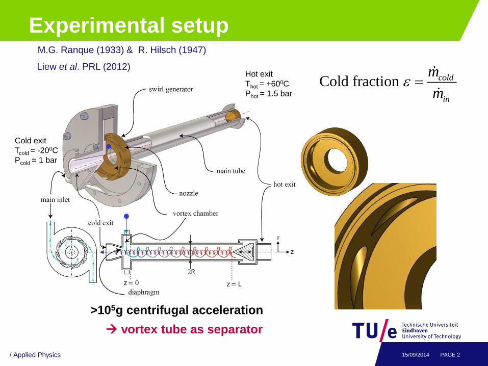
Experimental setup
/ Applied Physics PAGE 2 15/09/2014
>105g centrifugal acceleration
vortex tube as separator
Cold fraction cold
in
m
m
M.G. Ranque (1933) & R. Hilsch (1947)
Liew et al. PRL (2012) Hot exit
Thot = +600C
Phot = 1.5 bar
Cold exit
Tcold = -200C
Pcold = 1 bar
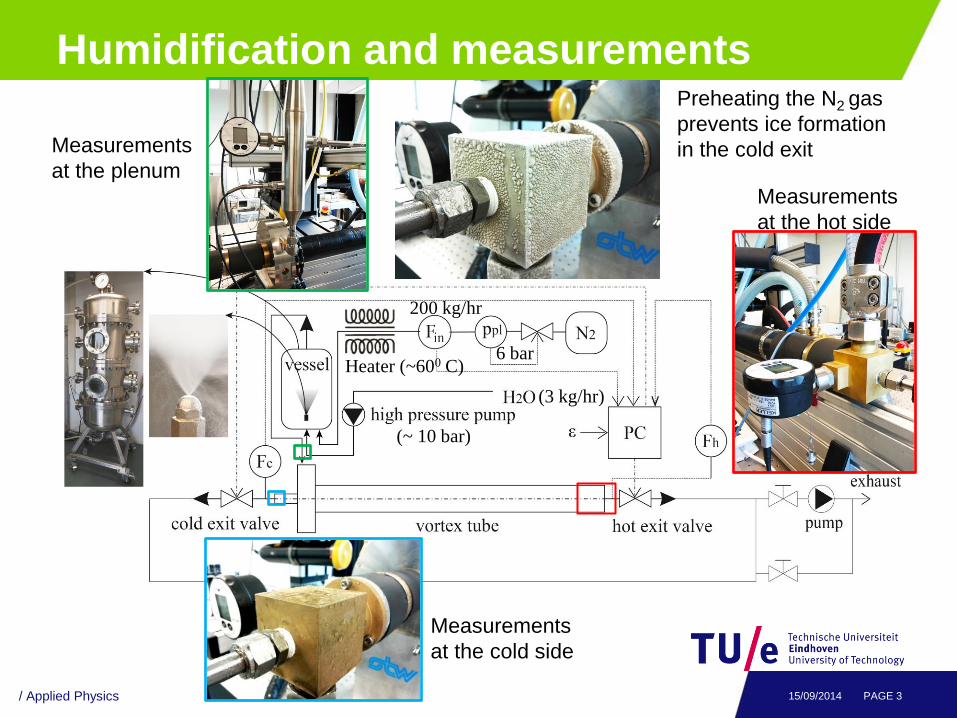
Humidification and measurements
/ Applied Physics PAGE 3 15/09/2014
6 bar
200 kg/hr
(3 kg/hr)
Heater (~600 C)
Preheating the N2 gas
prevents ice formation
in the cold exit
(~ 10 bar)
Measurements
at the plenum
Measurements
at the cold side
Measurements
at the hot side
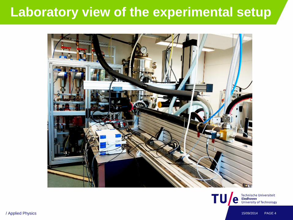
Laboratory view of the experimental setup
/ Applied Physics PAGE 4 15/09/2014
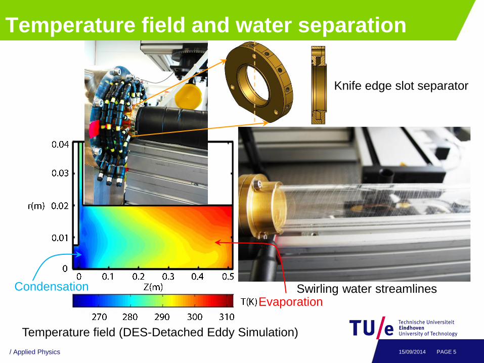
Temperature field and water separation
/ Applied Physics PAGE 5 15/09/2014
Condensation
Evaporation Swirling water streamlines
Temperature field (DES-Detached Eddy Simulation)
Knife edge slot separator
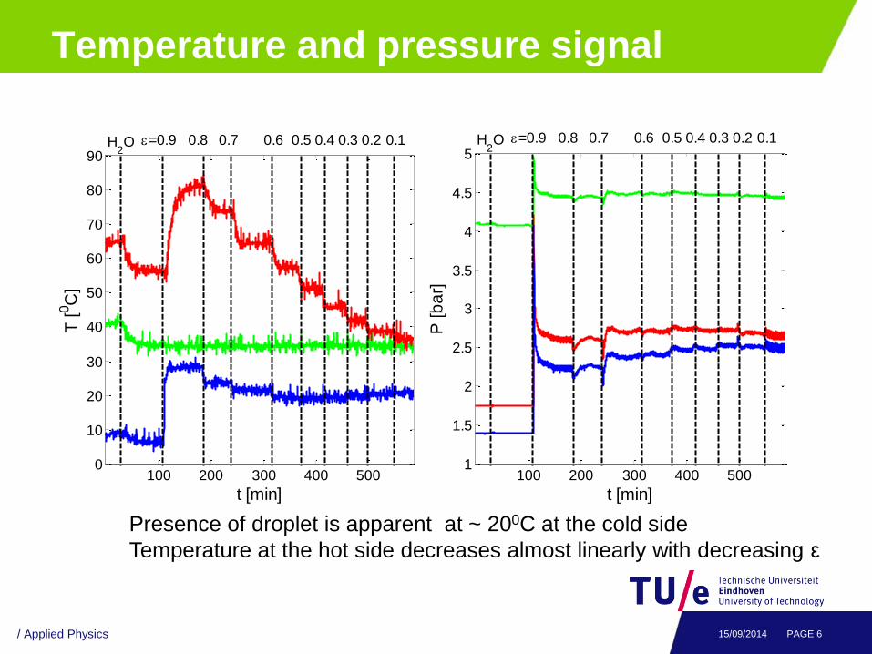
Temperature and pressure signal
100 200 300 400 5000
10
20
30
40
50
60
70
80
90
t [min]
T [
0C
]
H
2O =0.9 0.8 0.7 0.6 0.5 0.3 0.10.20.4
/ Applied Physics PAGE 6 15/09/2014
100 200 300 400 5001
1.5
2
2.5
3
3.5
4
4.5
5
t [min]
P [b
ar]
H
2O =0.9 0.8 0.7 0.6 0.5 0.3 0.10.20.4
Presence of droplet is apparent at ~ 200C at the cold side
Temperature at the hot side decreases almost linearly with decreasing ε
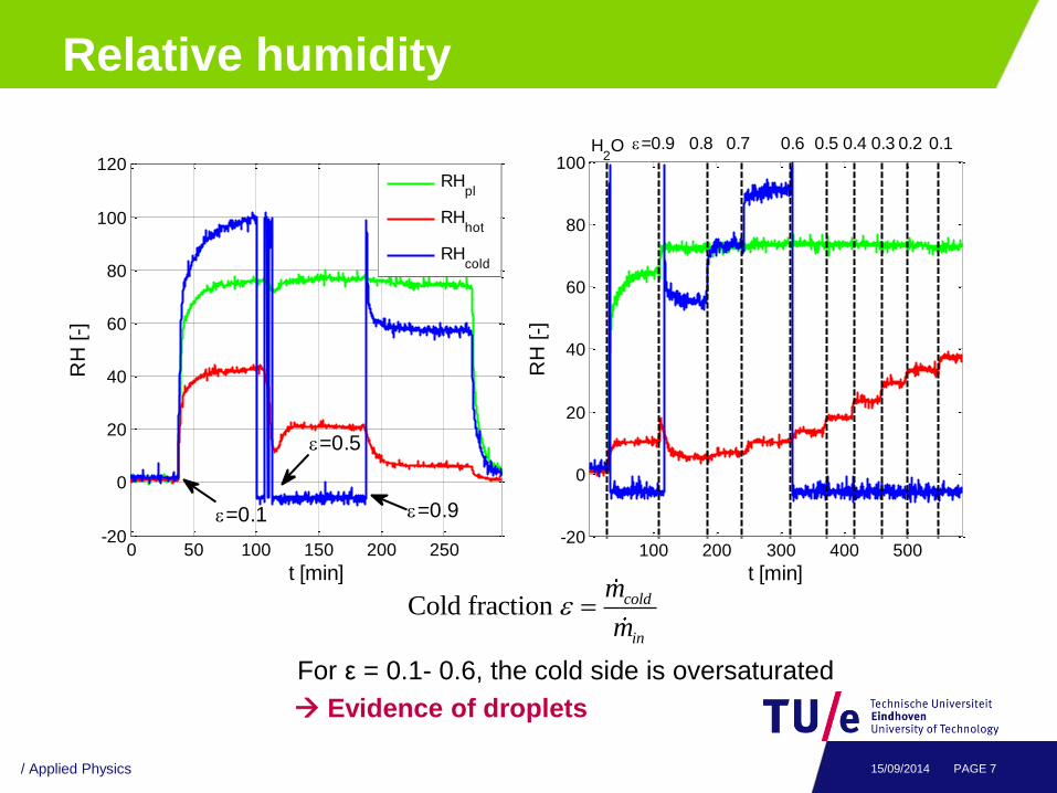
Relative humidity
/ Applied Physics PAGE 7 15/09/2014
0 50 100 150 200 250-20
0
20
40
60
80
100
120
t [min]
RH
[-]
RHpl
RHhot
RHcold
=0.1 =0.9
=0.5
100 200 300 400 500-20
0
20
40
60
80
100
t [min]
RH
[-]
0.40.70.8=0.9H2O 0.3 0.2 0.10.50.6
For ε = 0.1- 0.6, the cold side is oversaturated
Evidence of droplets
Cold fraction cold
in
m
m
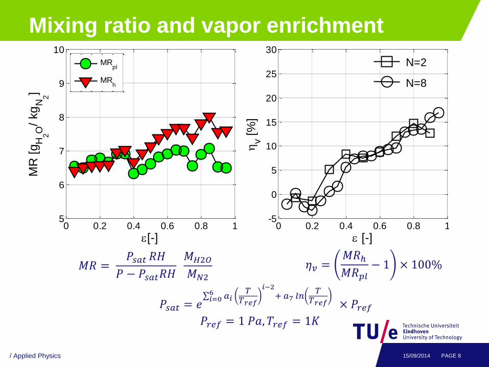
Mixing ratio and vapor enrichment
/ Applied Physics PAGE 8 15/09/2014
0 0.2 0.4 0.6 0.8 15
6
7
8
9
10
[-]
MR
[g
H2O
/ kg
N2
]
MRpl
MRh
0 0.2 0.4 0.6 0.8 1-5
0
5
10
15
20
25
30
[-]
v [
%]
N=2
N=8
𝑀𝑅 = 𝑃𝑠𝑎𝑡 𝑅𝐻
𝑃 − 𝑃𝑠𝑎𝑡𝑅𝐻 𝑀𝐻2𝑂𝑀𝑁2
𝑃𝑠𝑎𝑡 = 𝑒 𝑎𝑖
𝑇𝑇𝑟𝑒𝑓
𝑖−2
+ 𝑎7 𝑙𝑛𝑇
𝑇𝑟𝑒𝑓 6
𝑖=0× 𝑃𝑟𝑒𝑓
𝑃𝑟𝑒𝑓 = 1 𝑃𝑎, 𝑇𝑟𝑒𝑓 = 1𝐾
𝜂𝑣 =𝑀𝑅ℎ𝑀𝑅𝑝𝑙
− 1 × 100%
Conclusion and future work
Applied Physics / MTP PAGE 9 15/09/2014
Using different number of nozzles does not affect
droplet separation.
Vapor enrichment at the hot side is ~ 15%.
Effective liquid removal at the hot side is negligible.
The cold side of the RHVT becomes oversaturated
for the cold fraction of 10-50%, a potential implication
of applying an external separator at the cold side
for future work.