condair cp3mini · pdf file5.5.1 wiring diagram condair cp3mini 35 5.5.2 notes on electric...
TRANSCRIPT

2562341
EN
111
2
Condair CP3mini
MouNtiNg iNstruCtioNs
Electrode Humidifiers


3
Contents
1 Introduction 41.1 To the very beginning 41.2 Notes on the mounting instructions 4
2 For your safety 6
3 Product Overview 83.1 Models overview 83.2 Identificationoftheunit 83.3 Steamhumidifierconstruction 93.4 Functionaldescription 113.5 Humidificationsystemoverview 123.6 Options 143.7 Accessories 143.7.1 Accessories overview 143.7.2 Accessorydetails 153.8 Standarddelivery 163.9 Storing/Transportation/Packaging 16
4 Notes for the planning engineer 174.1 Selecting the unit version 174.1.1 Selecting the unit 174.1.2 Calculatingthemaximumrequiredsteamcapacity 184.2 Selectingtheoptionsanaccessories 184.3 Selecting the control system 19
5 Mounting and installation work 215.1 Importantnotesformountingandinstallationwork 215.2 Mounting the unit 225.2.1 Notesonlocatingandmountingtheunit 225.2.2 Mountingthehumidifier 245.2.3 Inspectingtheinstalledunit 255.3 Steaminstallation 265.3.1 Overviewsteaminstallation 265.3.2 Positioningandmountingofthesteamdistributionpipe 275.3.3 Installingthesteamdistributors 295.3.4 Installingthesteamhose 305.3.5 Installingthecondensatehose 315.3.6 Inspectingthesteaminstallation 325.4 Waterinstallation 335.4.1 Overviewwaterinstallation 335.4.2 Notesonwaterinstallation 335.4.3 Inspectingthewaterinstallation 345.5 Electricinstallation 355.5.1 WiringdiagramCondairCP3mini 355.5.2 Notesonelectricinstallation 365.5.3 InsertingtheCFcard 385.5.4 Inspectingtheelectricalinstallation 38
6 Productspecifications 396.1 Technicaldata 396.2 Unit dimensions 406.3 Declarationofconformity 41

4
LimitationThesubjectofthesemountinginstructionsisthesteamhumidifierCondairCP3miniinitsdif-ferent versions.Thevariousaccessoriesareonlydescribedinsofarasthisisnecessaryforproperoperationoftheequipment.Furtherinformationonaccessoriescanbeobtainedintherespectiveinstructions.
These mounting instructions is restricted to the installationofthesteamhumidifierCondairCP3miniandismeantforwelltrainedpersonnelbeingsufficientlyqualifiedfortheirrespectivework.
Themountinginstructionsaresupplementedbyvariousseparateitemsofdocumentation(operatinginstructions,sparepartslist,manualsforaccessories,etc.).Wherenecessary,appropriatecross-referencesaremadetothesepublicationsinthemountinginstructions.
1 Introduction
WethankyouforhavingpurchasedthesteamhumidifierCondairCP3mini.
ThesteamhumidifierCondairCP3miniincorporatesthelatesttechnicaladvancesandmeetsallrec-ognizedsafetystandards.Nevertheless,improperuseoftheCondairCP3minimayresultindangertotheuserorthirdpartiesand/orimpairmentofmaterialassets.
Toensureasafe,proper,andeconomicaloperationofthesteamhumidifierCondairCP3mini,pleaseobserveandcomplywithallinformationandsafetyinstructionscontainedinthepresentmanualaswellastheinstructionsgiveninthemanualsforthecomponentsusedinthehumidificationsystem.
Ifyouhavequestions,whicharenotorinsufficientlyansweredinthisdocumentation,pleasecontactyourCondairsupplier.Theywillbegladtoassistyou.
1.2 Notes on the mounting instructions
1.1 To the very beginning

5
Symbols used in this manual
CAUTION!Thecatchword“CAUTION”designatesnotesinthisdocumentationthat,ifneglected,maycausedamage and/or malfunction of the unit or other material assets.
WARNING!Thecatchword“WARNING”usedinconjunctionwiththegeneralcautionsymboldesignatessafetyanddangernotesinthisdocumentationthat,ifneglected,maycausetoinjury to persons.
DANGER!Thecatchword“DANGER”usedinconjunctionwiththegeneralcautionsymboldesignatessafetyanddangernotes in thisdocumentation that, ifneglected,may lead tosevere injury or even death of persons.
SafekeepingPleasesafeguardthesemountinginstructionsinasafeplace,whereitcanbeimmediatelyaccessed.Iftheequipmentchangeshands,thedocumentationshouldbepassedontothenewoperator.
Ifthedocumentationgetsmislaid,pleasecontactyourCondairsupplier.
Language versionsThesemountinginstructionsisavailableinvariouslanguages.PleasecontactyourCondairsupplierforinformation.
Copyright protectionThepresentmountinginstructionsareprotectedundertheCopyrightAct.Passing-onandreproduc-tionofthemanual(orpartthereof)aswellasexploitationandcommunicationofthecontentsareprohibitedwithoutwrittenpermissionbythemanufacturer.Violationofcopyrighttermsissubjecttolegalprosecutionandarisesliabilityforindemnification.
Themanufacturerreservestherighttofullyexploitcommercialpatentrights.

6
2 For your safety
GeneralEverypersonworkingwiththeCondairCP3minimusthavereadandunderstoodthemountingin-structionsbeforecarryingoutanyinstallationwork.Knowingandunderstanding thecontentsof themounting instructions isabasic requirement forprotectingthepersonnelagainstanykindofdanger,topreventfaultyinstallation,andtoinstallandoperatetheunitsafelyandcorrectly.
All ideograms, signs andmarkings applied to the unitmust be observed and kept in readablestate.
QualificationofpersonnelAllactionsdescribedinthepresentmountinginstructionsmustbecarriedoutonlybywell trained andsufficientlyqualifiedpersonnelauthorisedbytheowner.Forsafetyandwarrantyreasonsanyactionbeyondthescopeofthismanualsmustbecarriedoutonlybyqualifiedpersonnelauthorisedbythemanufacturer.
ItisassumedthatallpersonsworkingwiththeCondairCP3miniarefamiliarandcomplywiththeappropriateregulationsonworksafetyandthepreventionofaccidents.
Intended useThesteamhumidifierCondairCP3miniisintendedexclusivelyforairhumidificationviaasteamdistributor approved by the manufacturer(unitversionsCondair CP3mini PD..)or via the in-tegrated ventilation unit(unitversionsCondair CP3mini PR..)withinthespecifiedoperatingconditions(seechapter6“Productspecifications”).AnyothertypeofapplicationwithouttheexpresswrittenconsentofthemanufacturerisconsideredasnotconformingwiththeintendedpurposeandmayleadtotheCondairCP3minibecomingdangerous.Operationoftheequipmentintheintendedmannerrequiresthat all the information in these in-structions is observed (in particular the safety instructions).
Danger that may arise from the unit:The Condair CP3mini is mains powered.
DANGER!One may get in touch with live parts when the unit is open. Touching live parts may cause severe injury or danger to life.Prevention:Thesteamhumidifiermustbeconnectedtothemainsonlyafterallmountingandinstallationworkhasbeencompletedandthecoverhasbeenrelocatedproperly.

7
Behaviour in case of dangerAllpersonsworkingwiththeCondairCP3miniareobligedtoreportanyalterationstotheunitthatmayaffectsafetytotheownerwithoutdelayandtosecuresuchaunitagainstaccidentalpower-up.
ProhibitedmodificationstotheunitNomodificationsmustbeundertakenontheCondairCP3miniwithouttheexpresswrittenconsentofthemanufacturer.
Forthereplacementofdefectivecomponentsuseexclusivelyoriginal accessories and spare parts availablefromyourCondairsupplier.

8
3 Product Overview
3.1 Models overview
SteamairhumidifiersCondairCP3miniareavailableinthetwobasicversionsforductairhumidifi-cationanddirectroomairhumidification with different heating voltagesandsteam capacities of 2 kg/h and 4 kg/h.
Model Condair CP3miniDuct Room
PD2 PD4 PR2 PR4Max.steamcapacity 2kg/h 4kg/h 2kg/h 4kg/hHeatingvoltages 230V1~/50..60Hz
240V1~/50..60Hz200V2~/50..60Hz
Integratedventilationunit ––– XDisplayandcontrolunit XExternalOn/Offcontrol XExternalP/PIcontrol XInternalP/PIcontroller XAdmissiblecontrolsignals 0–5V,1–5V,0–10V,2–10V,
0–16V,3.2–16V,0–20mA,4–20mAOperatingparameter configurableviacontrolsoftware
3.2 Identificationoftheunit
Theidentificationoftheunitisfoundonthetypeplate(forthelocationofthetypeplateseeunitoverview):
Typedesignation Serialnumber(7digits) Month/Year
Heatingvoltage
Maximumsteamcapacityperunit
Admissiblewatersupplypressure
Powerconsumption
Controlvoltage
Fieldwithcertificationsymbols
Condair AG, CH-8808 PfäffikonType: CP3mini PD4 Ser.Nr.: XXXXXXX 06.09Heating Voltage: 230V / 1~ / 50...60Hz Power: 3.1 kW / 13.5 ASteam Capacity: 4.0 kg/h Ctrl.Voltage: 230V / 1~ / 50...60HzWater Pressure: 1...10 bar
Made in Switzerland

9
3.3 Steamhumidifierconstruction
1 Backpanel 2 Watercup 3 Watersupplyhose 4 Heatingelectrodes 5 Filling hose 6 Overflowhose 7 Steamcylinder 8 Inletvalve(notvisible) 9 Drainpump10 Waterdrainconnector(notvisible)11 Watersupplyconnector(notvisible) 12 Tub 13 Powerboard
14 Typeplate15 Remoteoperatingandfaultindicationboard
(Option)16 ControlboardwithCFcard 17 Unit switch18 Drainkey19 Displayandcontrolunit20 Operationstatusindicators(LED's)21 Intermediatepanel 22 Front cover23 Levelsensor24 Steamoutletconnector
1
2
4
5
7
6
9
3
17 13 1214 101516
23
22
21
24
11
19
18
20
8
Construction Condair CP3mini PD2/PD4

10
Construction Condair CP3mini PR2/PR4
1 Backpanel 2 Watercup 3 Watersupplyhose 4 Heatingelectrodes 5 Filling hose 6 Overflowhose 7 Steamcylinder 8 Inletvalve(notvisible) 9 Drainpump10 Waterdrainconnector(notvisible)11 Watersupplyconnector(notvisible) 12 Tub 13 Powerboard
14 Typeplate15 Remoteoperatingandfaultindicationboard
(Option)16 ControlboardwithCFcard 17 Unit switch18 Drainkey19 Displayandcontrolunit20 Operationstatusindicators(LED's)21 Unitintermediatepanel 22 Front cover23 Levelsensor24 Condensatehose25 Ventilationunit
1
2
4
5
7
6
9
3
17 13 1214 101516
23
22
21
24
25
11
19
18
20
8

11
3.4 Functional description
ThesteamhumidifierCondairCP3miniisapressurelesssteamgeneratorthatutilizesanelectrodeheating.ThesteamhumidifierCondairCP3miniisdesignedforairhumidificationviaasteamdistribu-tor(unitversionsCondairCP3miniPD..)orviatheintegratedventilationunit(unitversionsCondairCP3miniPR..).
Steam generationAnytimesteamisrequested,theelectrodesaresuppliedwithvoltage.Simultaneously,theinletvalveopensandwaterentersthesteamcylinderfromthebottomviawatercupandsupplyline.Assoonastheelectrodescomeincontactwiththewater,currentbeginstoflowbetweentheelectrodes,eventuallyheatingandevaporatingthewater.Themoretheelectrodesurfaceisexposedtowater,thehigheristhecurrentconsumptionandthusthesteamcapacity.Uponreaching therequestedsteamcapacity, the inletvalvecloses. If thesteamgenerationde-creasesbelowacertainpercentageoftherequiredcapacity,duetoloweringofthewaterlevel(e.g.becauseoftheevaporationprocessordrainage),theinletvalveopensuntiltherequiredcapacityisavailableagain.Iftherequiredsteamcapacityislowerthantheactualoutput,theinletvalveiscloseduntilthedesiredcapacityisachievedbyloweringofthewaterlevel(evaporationprocess).
Level monitoringAsensorprovidedinthesteamcylindercoverdetectswhenthewaterlevelgetstoohigh.Themo-mentthesensorcomesincontactwithwater,theinletvalvecloses.
DrainageAsaresultoftheevaporationprocess,theconductivityofthewaterincreasesduetoanescalatingmineralconcentration.Eventually,aninadmissiblyhighcurrentconsumptionwouldtakeplaceifthisconcentrationprocesswerepermittedtocontinue.Topreventthisconcentrationfromreachingavalue,unsuitablyhighfortheoperation,acertainamountofwaterisperiodicallydrainedfromthecylinderandreplacedbyfreshwater.
ControlThesteamproductioncanbecontrolledsteplesslyviatheinternaloranexternalcontinuouscontrollerorwithanOn/Offcontrolviaanexternalhumidistat.

12
3.5 Humidificationsystemoverview
1 Steamhumidifier 2 Steamconnector 3 Watersupplyconnector 4 Waterdrainconnector 5 Filtervalve(accessory“Z261”) 6 Manometer(installationrecommended) 7 Funnelwithsiphon(buildingside)
8 Waterdrainhose(accessory“DS22”) 9 Connectingcables10 Steamhose(accessory“DS22”)11 Condensatehose(accessory“KS10”)12 Steamdistributionpipe(accessory“41-...”)13 Steamnozzle(accessory“W21”)
System overview Condair CP3mini PD2/PD4
DS22
7
–
–
–
–
–
+
–
8
1
2
4
Z261
9
10
41-..
11
DS22
KS10
KS1011
12
41-.. 12
W2113
W2113
3
56
125...1250µS/cm1...10 bar1...40 °C
min. 10 %
min. 10 %
≥ 40 mm
min.
50 cm
ø22 mmG 3/4"
G 3/8"
min.
300 m
m
min. 20 %
min. 10 %
min. 10 %
min. 5 %
min. 5 %
Rmin.
300 m
m
Rmin. 300 mm
Ømin.
200 m
m
Ømin.
200 m
mPmax. 800 PaPmin. -800 Pa
Pmax. 800 PaPmin. -800 Pa

13
System overview Condair CP3mini PR2/PR4
1 Steamhumidifier 2 Ventilationunit 3 Watersupplyconnector 4 Waterdrainconnector 5 Filtervalve(accessory“Z261”)
6 Manometer(installationrecommended) 7 Funnelwithsiphon(buildingside) 8 Waterdrainhose(accessory“DS22”) 9 Connectingcables
–
–
DS228
7
1
2
6
Z261
9
5
3
4
125...1250µS/cm1...10 bar1...40 °C
min. 10 %
min. 10 %
≥ 40 mm
min.
50 cm
ø22 mmG 3/4"
G 3/8"

14
3.6 Options
Condair CP3miniPD2 PD4 PR2 PR4
Cable glands set with counter nuts–1xM20forcablediametersfrom7.0to13.0mm–1xM16forcablediametersfrom4.5to10.0mm–1xM12forcablediametersfrom2.5to6.5mm
1x CG
Radio humidity sensorRadiohumiditysensorsetconsistingofradiohumiditysensorandreceiverboardforthehumiditycontrolviatheinternalP/PIhumiditycontroller.Themaximumrangeoftheradiohumiditysensorinanopenroomis25mNote:theradiohumiditysensoraswellasthereceiverboardmustbeinstalled and configured only by a service technician of yourCondairrepresentative.
1x RH
Water drain hoseWaterdrainhose to lead thedrain line through thebackpanelof theunit.
1x WDH
Remote operating and fault indicationPCBwithrelaycontactsfortheconnectionofremotedisplaysfor“Opera-tion”,“Steam”,“Fault”and“Service”.
1x RFI
3.7 Accessories
3.7.1 Accessories overview
Accessories for water installation
Condair CP3miniPD2 PD4 PR2 PR4
Filter valve 1x Z261
Accessories for steam installation
Condair CP3miniPD2 PD4 PR2 PR4
Steam nozzle(Detailsseechapter3.7.2.1)
1x W21 –––
Steam distribution pipe(Detailsseechapter3.7.2.2)
1x 41-... –––
Steam hose / meter 1x DS22 –––Condensate hose / meter 1x KS10 –––
Accessories for humidity control
Condair CP3miniPD2 PD4 PR2 PR4
Humidity sensor for duct installation EGH110 –––
Humidity sensor for room installation ––– EGH130Duct humidistat HBC –––
Room humidistat ––– HSC

15
3.7.2 Accessory details
3.7.2.1 Steam nozzle W21
The steam nozzle W21canbemountedintheventilationducthorizontallyorvertically.Keepaminimum distance clearance (A) of 200 mmbetweennozzleopeningandtheoppositeductwall.
3.7.2.2 Steam distribution pipe 41-...
Thesteamdistributionpipesareselectedonthebasisoftheduct width(forhorizontalinstallation)or the duct height(forverticalinstallation)andthecapacityofthesteamhumidifier.Important! Alwaysselectthelongestpossiblesteamdistributionpipe(optimumhumidificationdis-tance).
Steam distribution pipes Type 41-... 1)
Length (L) steam distribution pipe
in mm 2)
Duct width (B)
in mm
41-200 200 210...40041-350 350 400...60041-500 500 550...75041-650 650 700...90041-800 800 900...110041-1000 1000 1100...130041-1200 1200 1300...1600
1) Material:CrNisteel2) speciallengthonrequest

16
3.8 Standard delivery
Thestandarddeliveryincludes:
– SteamhumidifierCondairCP3miniequippedwiththeoptionsorderedaccordingtochapter3.6,fixingset,mountinginstructions(thisdocument)andoperatinginstructions,packagedincardboardbox(WxHxD:351mmx729mmx265mm,shippingweight:7.4kg)
– Orderedaccessorieswithoperatinginstructionsaccordingchapter3.7,packedseparately
– Sparepartslist
3.9 Storing/Transportation/Packaging
StoringStoretheunitinaprotectedareameetingthefollowingrequirements:
– Roomtemperature:1...40°C– Roomhumidity:10...75%rh
TransportationForoptimumprotectionalwaystransporttheunitintheoriginalpackaging.Alwaysplacetheunitonitsbackside.
PackagingKeeptheoriginalpackagingoftheCondairCP3miniforlateruse.
Incaseyouwishtodisposeofthepackaging,observethelocalregulationsonwastedisposal.Neverdisposeofthepackagingtotheenvironment.

17
Condair CP3mini PD4 230V1
4.1 Selecting the unit version
4 Notes for the planning engineer
Toselecttheunitversionthefollowingstepsarerequired:
1. Selectingtheunitversionfromthetableinchapter4.1.1
2. Calculatingtherequiredmaximumsteamcapacityaccordingchapter4.1.2
4.1.1 Selecting the unit
Model Condair CP3miniDuct Room
PD2 1) PD4 1) PR2 2) PR4 2)
Heatingvoltages 230V1 230V1~/50..60Hz240V1 240V1~/50..60Hz200V2 200V2~/50..60Hz
Max.steamcapacity 2kg/h 4kg/h 2kg/h 4kg/hIntegratedventilationunit ––– XDisplayandcontrolunit XExternalOn/Offcontrol XExternalP/PIcontrol XInternalP/PIcontroller XAdmissiblecontrolsignals 0–5V,1–5V,0–10V,2–10V,
0–16V,3.2–16V,0–20mA,4–20mAOperatingparameter configurableviacontrolsoftware
1) Airconditioningsystemswithsupplyairportionupto66%2) fordirectroomhumidification

18
4.2 Selecting the options an accessories
Forselectingtheoptionsandaccessoriesseechapter3.6and3.7.
Themaximumrequiredsteamcapacitymustbecalculatedbasedononeofthefollowingformulas:
V•ρ mD= •(x2 - x1) 1000
or V mD= •(x2 - x1) 1000•ε
mD: maximumsteamdemandinkg/hV: volumeofsupplyairportionperhourinm3/h(forindirectroomhumidification)orroomvolume
tobehumidifiedperhourinm3/h(fordirectroomhumidification)ρ: specificgravityofairinkg/m3
ε: specificvolumeofairinm3/kgx2: desiredabsoluteroomairhumiditying/kgx1: minimumabsolutesupplyairhumidityin g/kgThevaluesforρ, ε, x2 and x1canbegatheredfromtheh,x-diagram or the Carrier-Diagramformoistairrespectively.
Important notes:– Therequiredmaximumsteamcapacitydependsonthespecificapplicationandtheinstallation.
Thecalculatedsteamcapacitybasedontheaboveformulas,theh,xdiagramandtheconditionoftheairtobehumidifieddoesnotconsideranysteamloss(e.g.duetocondensationinthesteamhosesandthesteamdistributors),anyheatlossoftheunitaswellasanyabsorptionorreleaseofhumidityofmaterialslocatedintheroombeinghumidified.Inaddition,thecalculatedsteamcapacitydoesnotconsideranylossescausedbythedrainingratedependingonthewaterqualityaswellasanylossesoccurifthesteamhumidifierisoperatedonamainscircuitwithagroundfaultcircuitinterrupter.
Thetotalamountoflossesdependsontheentiresystemandmustbetakenintoconsiderationwhencalculatingtherequiredsteamcapacity.IfyouhaveanyquestionsregardingthecalculationofthesteamcapacitypleasecontactyourCondairsupplier.
– Forsystemswherethemax.requiredsteamcapacityvariesextensively(e.g.fortestfacilitiesorforsystemswithvariableairvolumeflow,etc.),pleasecontactyourCondairsupplier.
4.1.2 Calculatingthemaximumrequiredsteamcapacity
Condair CP3mini PD4 230V1

19
CondairCP3mini
PD..
4.3 Selecting the control system
ThesteamhumidifiersCondairCP3miniaredesignedtobecontrolledwithOn/OffcontrolviaanexternalhumidistatorwithcontinuouscontrolviaanexternalP/PIhumiditycontrollerortheinternalP/PIhumiditycontroller.
– System 1: Room humidity controlSystem1issuitedfordirectroomhumidificationandair conditioning systems with mainly recirculated air.Thehumiditysensororhumidistatrespectivelyispreferablylocatedintheroomitselforintheexhaustairduct.
A1 humidity sensorB1 ventilationinterlockB2 airflowmonitorB3 safetyhumidistatB4 humidistatPII internalP/PIcontrollerPIE externalcontinuouscontroller (e.g.PIcontroller)Y inputsignalfromA1
CondairCP3miniPR...
A1 humidity sensorB1 ventilationinterlockB2 airflowmonitorB3 safetyhumidistatB4 humidistatPII internalP/PIcontrollerPIE externalcontinuouscontroller (e.g.PIcontroller)Y inputsignalfromA1

20
– System 2: Room humidity control with continuous limitation of the supply air humiditySystem2issuitedforairconditioningsystemswithalarge portion of supply air, low supply air temperature, post-humidification, or variableairflowvolume.Ifthesupplyairhumidityexceedsthepresetvalue,thecontinuouslimitationiseffectedpriortotheroomhumiditycontrol.Thehumiditysensor(A1)ispreferablylocatedintheexhaustairductorintheroomitself.Thehumiditysensor(A2)forthelimitationofthesupplyairhumidityislocatedinthesupplyairductafterthesteamdistributionpipe.Thiscontrolsystemrequiresacontinuouscontrollerwiththeoptiontoconnectasecondhumiditysensor.Attention! Thecontinuouslimitationofthesupplyairhumidityisnosubstituteforthesafetyhumi-distat.
CondairCP3mini
PD..
CondairCP3miniPR...
A1/2 humidity sensorB1 ventilationinterlockB2 airflowmonitorB3 safetyhumidistatPII InternalP/PIcontrollerPIE Externalcontinuouscontroller (e.g.PIcontroller)Y inputsignalfromA1Z inputsignalfromA2
A1/2 humidity sensorB1 ventilationinterlockB2 airflowmonitorB3 safetyhumidistatPII InternalP/PIcontrollerPIE Externalcontinuouscontroller (e.g.PIcontroller)Y inputsignalfromA1Z inputsignalfromA2
Please contact your Condair supplier, if your application meets the following conditions:– Humidificationofsmallroomsupto200m3
– Airconditioningsystemswithahighnumberofairexchanges– Systemswithvariableairvolumeflow– Testfacilitieswithextremecontrolaccuracyrequirements– Roomswithahighvariationinmax.steamcapacity– Systemswithtemperaturefluctuations– Coldroomsandsystemswithdehumidification

21
5 Mounting and installation work
QualificationofpersonnelAllmountingandinstallationworkmustbecarriedoutonlybywellqualifiedpersonnelauthorisedby the owner.Itistheowner’sresponsibilitytoverifyproperqualificationofthepersonnel.
General note Strictlyobserveandcomplywithallinformationgiveninthepresentmountinginstructionsregardingthelocationoftheunitandtheinstallationofwater,steamandelectricity.
Observe and comply with all local regulationsdealingwithwater,steamandelectricalinstalla-tions.
SafetySomeinstallationworkrequiresremovaloftheunitcover.Pleasenotethefollowing:
DANGER! Danger of electrical shock!Youmaygetintouchwithlivepartswhentheunitisopen.Thesteamhumidifiermustbeconnectedtothemainsonlyafterallmountingandinstallationworkhasbeencompletedandthecoverhasbeenrelocatedproperly.
CAUTION!The electronic components inside the humidifier are very sensitive to electrostatic discharge.Whentheunitisopenforinstallationwork,appropriatemeasuresmustbetakentoprotectthesecomponentsagainstdamagecausedbyelectrostaticdischarge(ESDprotection).
5.1 Important notes for mounting and installation work

22
5.2 Mounting the unit
5.2.1 Notes on locating and mounting the unit
min
. 500
mm
min. 2 m
650 m
m
min. 250 mm
265 mm
min. 250 mm
11.2 kg
175 mm
min
. 400
mm
min. 600 mm
650 m
mm
in. 6
00 m
m
175 mm
265 mm
11.2 kg
min. 250 mm
min. 250 mm
Condair CP3mini PD..
Condair CP3mini PR..
Note: The minimum spaces apply foraroomatmosphereof15°Candmax.60 %rh. For lower temperatures and/orhigherhumiditythevaluesshouldbeadjustedaccordingly
Note:Inordertoachieveauniformdis-tributionofthehumiditywithintheroom,additionalfactorssuchastheroomsize,the room height, etc., must be takenintoconsiderationbesidesobservingtheminimumdistances.Ifyouhavequestionsconcerningthedirectroomhumidification,pleasecontactyourCondairsupplier.
Inordertoavoiddeteriorationofcompo-nents,nocorrosion/water-sensitivecom-ponentsshouldbestoredbelowtheunitandinthevicinityoftheflowofsteam.

23
To ensure proper functioningofthesteamhumidifierandtoobtainanoptimalefficiency,thefollow-ingpointsmustbeconsideredandobservedwhenchoosingthelocationforthesteamhumidifier:
– Installthesteamhumidifierinsuchamannerthatitisfreely accessiblewithsufficientspaceavailable formaintenancepurposes.Theminimum distancesshown in theprecedingfiguremustbemaintained.
– Installthesteamhumidifiersothatthelength of the steamhoseiskeptasshortaspossible(max. 4 m)andthattheminimum bend radius (R= 300 mm)andup-slope (20 %) or down-slope (5 %)ofthesteamhoseisobserved(seechapter5.3.4).
– DuringoperationsteamisblownoutviatheoutletopeningofthesteamhumidifierstypePR...Therefore,locatethesteamhumidifierstypePR..insuchaway,thatnopersonscanbehurtbythesteamflow.
– The steamhumidifiersCondairCP3mini are designed forwall-mounting.Make sure that theconstruction(wall,pillar,floor-mountedconsole,etc.)towhichthehumidifiersaretobemounted,offersasufficientlyhighload-bearingcapacity(takenoticeoftheweightinformationfoundinthedimensionsandweightstableabove),andissuitablefortheinstallation.
CAUTION!Do notmountthesteamhumidifierdirectlytotheventilationduct(insufficientstability).
– ThebackpaneloftheCondairCP3miniisretainingheatduringoperation(max.surfacetempera-tureofthemetalhousingapprox.60-70°C).Makesure,therefore,thattheconstruction(wall,pillar,etc.)towhichtheunitsaretobemounted,doesnotconsistofheat-sensitivematerial.
– TheCondairCP3miniisprotectedaccordingtoIP20.Makesuretheunitsareinstalledinadrip-prooflocationandtheadmissibleambientconditionsarecompliedwith.
– ThesteamhumidifierCondairCP3minimayonlybeinstalledinroomswithafloordrain.
CAUTION!IfforsomereasontheCondairCP3minimustbeinstalledinalocationwithoutfloordrain,itismandatorytoprovidealeakagemonitoringdevicetosafelyinterruptthewatersupplyincaseofleakage.
– WhenfixingtheCondairCP3miniuseonlythefixingmaterialssuppliedwiththeunit.Iffixingwiththematerialssuppliedisnotpossibleinyourparticularcase,selectamethodoffixingthatisofsimilarstability.

24
5.2.2 Mountingthehumidifier
Procedure1. Marktheattachmentpoints“A”onthewallwiththeassistanceofaspiritlevel.
2. Drilltheholesfortheattachmentpoints“A”(diameter:8mm,depth:40mm),theninsertthesup-pliedplasticplugs.
3. Fixthewallsupportwiththetwolongscrewsandwashers“B”.Beforetighteningthescrews,adjustthewallsupportverticallyandhorizontallywiththespiritlevel.
4. Hangtheunitupontothewallsupport.
5. Loosenthefixingscrewofthefrontcoveronthebottomsideoftheunitafewturns,thenremovethefrontcover.
6. Removealltransportationlocks(steamclinder,drainpump,watercup)insidetheunit.
7. Undothesteamcylinder:releasethehoseclamponthesteamconnectorofthesteamcylinder,thendetachthesteamhosefromthesteamconnector.Removetheplugsfromtheelectrodesandfromthelevelsensor.Carefullyliftsteamcylinderoutofthecylinderreceptacle,thenremoveittothefront.
8. Undothetwoscrewsoftheintermediatepanel.Then,carefullyremovetheintermediatepaneltothefront,swivelittotheleftandhangitontothepinsofthebackpanel.
9. Fixunittothewallsupportusingthetwoscrews“C”andtothewallusingthescrewandwasher“D”.Beforetighteningthescrews,readjusttheunitverticallywiththespiritlevel.
10.Assembletheunitinthereversesequence.
420
mm
33 m
m
120 mm
AA
A
132 mm132 mm
D
C
B
B
478
mm
154
mm
166 mm97mm
Wallbreak-throughtoleadtheconnectingcablesaswellasthewatersupplypipeandthewaterdrainhose(option WDH)throughrearwallintotheunit

25
5.2.3 Inspecting the installed unit
Checkthefollowingpoints:
Istheunitinstalledinthecorrectplace(seechapter5.2.1)?
Isthesupportingsurfacestableenough?
Istheunitcorrectlyaligned,verticallyandhorizontally?
Istheunitproperlysecured(seechapter5.2.2)?
Arealltransportationlocksinsidetheunitremoved?
Istheunitreassembledcorrectlyandthefrontpanelfixedwiththescrew?

26
5.3 Steam installation
5.3.1 Overview steam installation
KS10
–
–
–
–
+
41-..
KS10
41-..
W21
W21
DS22
min.
300 m
m
min. 20 %
min. 10 %
min. 10 %
min. 5 %
min. 5 %
Rmin.
300 m
m
Rmin. 300 mm
Ømin.
200 m
m
Ømin.
200 m
m
Pmax. 800 PaPmin. -800 Pa
Pmax. 800 PaPmin. -800 Pa

27
5.3.2 Positioning and mounting of the steam distribution pipe
Thelocationforthesteamdistributionpipesshouldbedeterminedatthetimeofdimensioningtheairconditioningsystem.Pleasenotethefollowinginstructionstoensureproperhumidificationoftheductair.
CalculatingthehumidificationdistanceThewater vapour, emitting from the steam distribution pipes, requires a certain distance to beabsorbedbytheambientairsothatitisnolongervisibleassteam.Thisdistanceisreferredtoashumidificationdistance“BN”andservesasabasisforthedeterminationoftheminimumdistancesfromtheupstreamcomponentsinthesystem.
HumidificationdistanceBN Expansionandmixingzone
ϕ1:Supplyairhumiditybeforehumidificationϕ2:Supplyairhumidityafterhumidification
Thecalculationof thehumidificationdistance “BN” isdependentonseveral factors.Fora roughestimationofthehumidificationdistance“BN”,thefollowingtableisuseful.Recommendedstandardvalueslistedinthistablearebasedonasupply-airtemperaturerangeof15°Cto30°C.
Humidity at inletϕ1 in %rh
LengthofhumidificationdistanceBN in m Humidity at outlet ϕ2 in %rh
40 50 60 70 80 905 0,9 1,1 1,4 1,8 2,3 3,5
10 0,8 1,0 1,3 1,7 2,2 3,420 0,7 0,9 1,2 1,5 2,1 3,230 0,5 0,8 1,0 1,4 1,9 2,940 – 0,5 0,8 1,2 1,7 2,750 – – 0,5 1,0 1,5 2,460 – – – 0,7 1,2 2,170 – – – – 0,8 1,7
ϕ1in%rh: Relativesupplyairhumiditypriortohumidificationatthelowestsupplyairtemperatureϕ2in%rh: Relativesupplyairhumidityafterthesteamdistributionpipeatmaximumcapacity
Example
given: ϕ1=30%rh,ϕ2=70%rhhumidificationdistanceBN: 1.4 m

28
Minimum distances to be observedTopreventthewatervapour,thatisemittingfromthesteamdistributionpipe,fromcondensingondownstreamsystemcomponents,aminimumdistancetothesteamdistributionpipemustbeobserved(dependsonthehumidificationdistance“BN”).
before/after constriction after expansion before bend
before branch before diffuser before control sensor
before/afterfilter/register before/afterfan,zoneexit
2,5xBNbeforeaerosolfilter
Installation notes and dimensionsThesteamdistributionpipesaredesignedforeitherhorizontalinstallation(ontheductwall)or,withaccessories,forvertical installation(intheductfloor).Theoutletorificesshouldalwayspointupwardsandatrightanglestotheairflow.
Ifpossible,thesteamdistributionpipesshouldbeinstalledonthepressure sideoftheduct(max. duct pressure 800 Pa).Ifthesteamdistributionpipesareinstalledonthesuctionsideoftheduct,the maximum vacuum must not exceed 800 Pa.
Selectalocationfortheinstallation,tailoredtosuityourduct(seethefollowingillustrations)andpositionthesteamdistributionpipesintheductsothatauniformdistributionofsteamisachieved.
1.5 x BN * BN BN5 cm

29
1/21/2
H
1/21/2
H
1/3
2/3H
In positioning the steamdistribution pipe/steamnozzle, the following dimensions should be ob-served:
H min.= 250 mm H≥400mm H min.= 200 mm
Guidelines for dimensioning the ventilation ducts– Tofacilitatetheinstallationofthesteamdistributionpipesandforcontrolpurposes,asufficiently
sizedcontrolopeningshouldbeplanned.
– Withintherangeofthehumidificationdistance,theventilationductshouldbewaterproofed.
– Airductspassingthroughcoldroomsshouldbeinsulatedtopreventthehumidifiedairfromcon-densingalongtheductwall.
– Poorairflowconditionswithintheairduct(e.g.causedbyobstacles,tightbends,etc.)canleadtocondensationofthehumidifiedair.
– Steamdistributionpipesmustnotbemountedtoroundducts.
IfyouhavequestionsrelatingtothedimensioningofventilationductsincombinationwithsteamhumidifiersCondairCP3mini,contactyourCondairsupplier.
5.3.3 Installing the steam distributors
DetailedinformationontheinstallationofthesteamnozzleW21andthesteamdistributionpipe41-...canbefoundintheseparatemountinginstructionsforthisproducts.
min. 85 mm
min
.= 2
00 m
m
min.= 200 mm

30
5.3.4 Installing the steam hose
Important! UseoriginalCondairsteamhoseexclusively.Othertypesofsteamhosescancauseundesiredoperationalmalfunctions.
Instructions for the hose layoutThehoselayoutdependsonthepositionofthesteamdistributionpipe:
– Steamdistributionpipeismountedmorethan300mmabovethetopedgeofthehumidifier:
Initially,leadthesteamhosewithanupslope of at least 20% over a minimum height of 300 mm abovethetopedgeoftheunit,thenleadthehosewithaminimum upslope of 20%and/oraminimum downslope of 5%tothesteamdistributionpipe.
– Steamdistributionpipeismountedlessthan300mmabovethetopedgeofthehumidifier:
Initially, lead the steamhosewith anupslope of at least 20% over a minimum height of 300 mm abovethetopedgeoftheunit,thenleadthehosedowntothesteamdistributionpipewithaminimum slope of 5 %.
– Thesteamhoseshouldbekeptasshortaspossible(max. 4 m)whileobservingtheminimum bend radius of 300 mm. Important!Allowancemustbemadeforapressure loss of 10 mm water column (approx. 100 Pa)permetersteamhose.Note:Ifyourparticularinstallationexceedsthemaximumsteamhoselengthof4mcontactyourCondair representative. Inanycase,steamhoses longer than4mmustbe insulated in theirentire length.
– Reductionsinthecrosssectionsuchaskinksshouldbeavoidedthroughouttheentirelengthofthehose.Theinstallationofastopcockinthesteamhoseisnotpermissible.
min.
300 m
m
Rmin.
300 m
m
min. 5 % min. 20 %
max.
4 m
min.
300 m
mRmin.
300 mm
min. 20 %
max.
4 m
max.
4 m
min. 5 %
Rmin.
300 m
m
max.
4 m
min.
300 m
m
min. 20 %
min.
300 m
m
min. 20 %min. 5 %
Rmin. 300 m
mmin. 20%

31
– Steamhosesmustbepreventedfromsagging(condensatepockets);ifnecessary,supportwithpipeclamps,trough,orwallbrackets,orinstallacondensatedraininthesteamhose.
– Important!Whendecidingonthelengthandlayoutofthehose,itshouldbenotedthatthesteamhosemaybecomesomewhatshorterwithprogressiveageing.
Securing the hoseThesteamhosemustbesecuredtothesteamdistributionpipeandhumidifiersteamoutletbymeansofhose clamps. Caution!Donotovertightenthehoseclamponthesteamconnectorofthesteamhumidifier.
SteamlinewithfixedpipingForsteamlineswithfixedpiping,thesame instructions apply to the laying of the pipingasalreadydescribed.Thefollowingadditionalnotesshouldbeobserved:– The minimum internal diameter of 22 mm shouldbeappliedoverthewholelengthofthepip-
ing.– UseexclusivelyCuorstainlesssteelpipes(min.DIN1.4301).– Tominimizethecondensateformation(=loss),thesteampipesmustbeinsulated.– The minimum bend radiusforsolidpipesis4-5 x internal diameter.– Connectionofthesteampipestothesteamdistributionpipeandsteamhumidifieriseffectedby
meansofshortlengthsofsteamhosesecuredwithhoseclamps.– Important! Allowancemustbemadeforapressure loss of 10 mm water column (approx.
100 Pa)permeterlengthorper90°bend.
5.3.5 Installing the condensate hose
Important! Use originalCondair condensate hose exclusively.Other types ofhoses can causeoperationalmalfunctions.
Thehoselayoutdependsonthepositionofthesteamdistributionpipe:
– Steamdistributionpipeismountedmorethan300mmabovethetopedgeofthehumidifier:
min.
300 m
m min. 20 %
Ømin. 200 mm
min.
300 m
m
min. 20 %
Ømin. 200 mm
Leadthecondensatehosedowntothehumidifierwithaminimum slope of 20 %,intheformofa siphon (min. hose bend diameter Ø200 mm ).Then,leadthehoseintotheunitthroughthebreak-throughonthetopsideoftheunitandinsertitabout2cmintothespecifiedopeningofthewatercup.

32
– Steamdistributionpipeismountedlessthan300mmabovethetopedgeofthehumidifier:
Leadthecondensatehosedownwithaminimum slope of 20 %,intheformofasiphon (min. hose bend diameter Ø200 mm),directlyintoadischargefunnel.
Important! Beforeputtingtheunitintooperation,thesiphonofthecondensatehosemustbefilledwithwater.
5.3.6 Inspecting the steam installation
Usethefollowingchecklisttoascertainthatthesteaminstallationwasperformedcorrectly:
– Steamdistributor
Steam distributors (steam distribution pipe or steam nozzle) correctly positioned and se-cured?
Aretheoutletorificesatrightanglestotheairflowdirection?
– Steamhose
Maximumlengthof4m?
Minimumbendradiusof300mm(4-5xinternaldiameterwithfixedpiping)?
Havetheinstructionsforhosepositioningbeenfollowed?
Steamhose:nosagging(condensatepocket)orcondensatedrainwithsiphon(hosebendwithaminimumdiameterof200mm)installedatthelowestpoint?
Rigidsteamlines:properlyinsulated?Correctinstallationmaterialused?Minimuminternaldiametermaintained?
Steamhosesecurelyattachedwithclamps?
Heatexpansionduringoperationandshorteningofthehosewithageingtakenintoconsidera-tion?
– Condensatehose
Downslopeofatleast20%?
Siphon(min.ø200mm)existingandfilledwithwater?
Condensatehosecorrectlyfixedandnotkinked?
min.
300 m
mmin. 20 %Ømin.
200 m
m
min.
300 m
m
min. 20 %
Ømin. 20
0 mm

33
5.4 Water installation
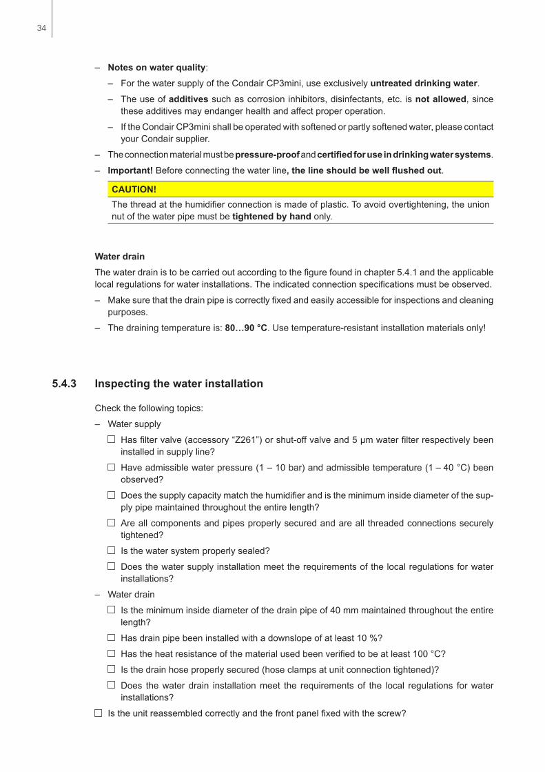
5.4.1 Overview water installation
Fortheconnectionofthewatersupplylineandthewaterdrainline,theunitmustbeopened.Proceedasfollows:loosenthefixingscrewofthefrontcoveronthebottomsideoftheunitafewturns,thenremovethefrontcover.Undothetwoscrewsoftheintermediatepanel.Then,carefullyremovetheintermediatepaneltothefront,swivelittotheleftandhangitontothepinsofthebackpanel.
Water supplyThewatersupplyistobecarriedoutaccordingtothefigurefoundinchapter5.4.1andtheapplicablelocalregulationsforwaterinstallations.Theindicatedconnectionspecificationsmustbeobserved.
– Theinstallationofthefiltervalve(accessory“Z261”,alternativelyashut-offvalveanda5µmwaterfiltercanbeused)shouldbemadeascloseaspossibletothesteamhumidifier.
– Admissiblemainspressure1.0 to 10.0 bar (hammer-free system)Formainspressures>10bar,theconnectionmustbemadeviaapressurereducingvalve(ad-justedto1.0bar).Formainspressures<1.0barpleasecontactyourCondairsupplier.
5.4.2 Notes on water installation
–
DS22
–
Z261
WDH
125...1250µS/cm1...10 bar1...40 °C min. 10 %
min. 10 %
≥ 40 mm
min.
50 cm
ø22 mmG 3/4"
G 3/8"
34
– Notesonwaterquality:
– ForthewatersupplyoftheCondairCP3mini,useexclusivelyuntreated drinking water.– Theuseofadditivessuchascorrosioninhibitors,disinfectants,etc.is not allowed, since
theseadditivesmayendangerhealthandaffectproperoperation.
– IftheCondairCP3minishallbeoperatedwithsoftenedorpartlysoftenedwater,pleasecontactyourCondairsupplier.
– Theconnectionmaterialmustbepressure-proofandcertifiedforuseindrinkingwatersystems.
– Important!Beforeconnectingthewaterline,thelineshouldbewellflushedout.
CAUTION!Thethreadatthehumidifierconnectionismadeofplastic.Toavoidovertightening,theunionnutofthewaterpipemustbetightened by hand only.
Water drainThewaterdrainistobecarriedoutaccordingtothefigurefoundinchapter5.4.1andtheapplicablelocalregulationsforwaterinstallations.Theindicatedconnectionspecificationsmustbeobserved.
– Makesurethatthedrainpipeiscorrectlyfixedandeasilyaccessibleforinspectionsandcleaningpurposes.
– Thedrainingtemperatureis:80…90 °C.Usetemperature-resistantinstallationmaterialsonly!
5.4.3 Inspecting the water installation
Checkthefollowingtopics:
– Watersupply
Hasfiltervalve(accessory“Z261”)orshut-offvalveand5µmwaterfilterrespectivelybeeninstalledinsupplyline?
Haveadmissiblewaterpressure(1–10bar)andadmissibletemperature(1–40°C)beenobserved?
Doesthesupplycapacitymatchthehumidifierandistheminimuminsidediameterofthesup-plypipemaintainedthroughouttheentirelength?
Areallcomponentsandpipesproperlysecuredandareallthreadedconnectionssecurelytightened?
Isthewatersystemproperlysealed?
Doesthewatersupplyinstallationmeettherequirementsofthelocalregulationsforwaterinstallations?
– Waterdrain
Istheminimuminsidediameterofthedrainpipeof40mmmaintainedthroughouttheentirelength?
Hasdrainpipebeeninstalledwithadownslopeofatleast10%?
Hastheheatresistanceofthematerialusedbeenverifiedtobeatleast100°C?
Isthedrainhoseproperlysecured(hoseclampsatunitconnectiontightened)?
Does thewaterdrain installationmeet the requirementsof the local regulations forwaterinstallations?
Istheunitreassembledcorrectlyandthefrontpanelfixedwiththescrew?

35
5.5 Electric installation
5.5.1 Wiring diagram Condair CP3mini
A1 Controller(active)orhumiditysensorA2 Controller(passive),
setjumperonJP1(5V)andremovejumperfromJP2(24V)A3 On/Offcontroller,
setjumperonJP2(24V)andremovejumperfromJP15V)A4 LimitationsignalBAT Backupbattery(CR1632,Lithium3V)B1 VentilationinterlockB2 SafetyhumidistatB3 AirflowmonitorF1 Internalfuse“Powerboard”:controlsignal(200mA,fastacting)F2 Internalfuse“Powerboard”:control5V(1A,slowacting)F3 Internalfuse“Powerboard”:control24V(1A,slowacting)F4 Internalfuse“Powerboard”:controlvoltage(1A,slowacting)F5 Externalfusesupplyvoltage(seetableinchapter5.5.2)H1 RemoteoperatingandfaultindicationJ Shortcircuited,ifnoexternalmonitoringdevicesareconnected
JP1 OutletvoltageatX1,V+=5VJP2 OutletvoltageatX1,V+=24VJP3 DonotsetjumperJP4 JumpermustbesetK Externalsafetychain(24VDC)M Ventilationunit(unittypePR...only)Q3 ExternalServiceswitchvoltagesupplyS1 Unit switchREL4 RelayHeatingvoltageU1 ReceiverradiohumiditysensorX1 ConnectorcontrolsignalX3 Connectorventilationunit(unittypePR...only)X4 ConnectorlimitsignalX6 ConnectorexternalsafetychainX8 Connector Unit switchX9 Connectionterminalvoltagesupply
SWITCH
J1 CPU BOARD
REL4MAIN CONTACT
LCTRL PWR
J1
J8Driver
Fault Remote
CF Card
J11Keypad / LED
H1
Sensor SupplyMax. 60mA
100 mAF1
Analog Out1
12
23
4
MAIN SUPPLYX9
CONT.SIGN LIM. SIGN SAFETY
PE
L N PE
F21AT
F31AT
F1200mAF
CYLINDER LEVEL SENSOR
X7X3
X1 X4 X6
DET
DRAINL N L N
INLET
FAN- FAN+
J7L
J6N
J4N
FAN
A2
A3
A4
L1 N
J
F5
Q3
M
U1
S1
200..240V1~ 50..60Hz
L1 L2
F5
Q3
200V2~ 50..60Hz
rot
schw
arz
ServiceError Unit ONSteam
CTRL V+
12 12 123
GNDBASI
C0-
10V
On/
Off
24V 5V
PRO
JP4
JP3
JP2
JP1
LIMGND SC1SC2
X8F4 1AT
N L SW N SWL
V+GND CTRL GND LIM SC1SC2
24V 5V
JP2
JP1
24V 5V
JP2
JP1
– +P / PIA1
V+GND CTRL
V+GND CTRL
140...10kΩ
ON / OFF
– +P / PI K
B3
B2
B1
CR1632 BAT
Controlboard Powerboard
Remoteindicationboard
no function

36
5.5.2 Notes on electric installation
Important notes– Fortheelectricinstallation,theunitmustbeopened.Proceedasfollows:loosenthefixingscrew
ofthefrontcoveronthebottomsideoftheunitafewturns,thenremovethefrontcover.Undothetwoscrewsoftheintermediatepanel.Then,carefullyremovetheintermediatepaneltothefront,swivelittotheleftandhangitontothepinsofthebackpanel.
– Theelectricinstallationmustbecarriedoutaccordingtothewiringdiagraminchapter5.5.1,thenotesonelectricinstallationaswellastheapplicablelocalregulations.Allinformationgiveninthewiringdiagrammustbefollowedandobserved.
– Allcablesmustbeleadintotheunitviathecableopeningsequippedwithcableglands(e.g.op-tion“CG-cablegland”).
– Maximumcablelengthandrequiredcrosssectionperwiremustbeobserved.
Supply voltage (heating voltage)
CAUTION!Beforeconnecting,ensurethatthemainsvoltagecorrespondswiththeunit voltage(seetypeplate).
TheCondairCP3miniistobeconnectedtothemainssupplyinaccordancewiththewiringdiagram,viaaservice switch “Q3”(disconnectingdevicewithaminimumcontactopeningof3mmisanessentialrequirement)andan fuse “F5”(essentialrequirement,fusesaretobeasdetailedinthefollowingtable).Thesupplywiringistobefedintotheunitviaatension-relievingdevice(cablegland)andconnectedtotheterminals “X9”.
Heating voltage Max. steam capacity[kg/h]
Nominal power [kW]
Nominal current [A]
Main fuse F5[A]
230V1~/50..60Hz2 1.6 7.0 134 3.1 13.5 16
240V1~/50..60Hz2 1.6 6.6 134 3.1 12.9 16
200V2~/50..60Hz2 1.6 8.0 2x 134 3.1 15.5 2x 20
Thecross-sectionofthemainscablemustcomplywiththeapplicablelocalregulations.
Externalsafetycircuit“K”Toguaranteethesafetyofthehumidificationsystem,monitoringtheoperationbymeansofasafetycircuitisanabsoluterequirement.
Toaccomplishthis,thepotential-free contacts (max. contact loading 30V/0.15A)ofexternalmoni-toringdevices(e.g.safetyhighlimithumidistat,airflowmonitor,ventilationinterlock,etc.)arecon-nectedinseriestothecontacts“SC1”and“SC2”oftheterminalplug“X6”inaccordancewiththewiringdiagram.
If,forwhateverreason,noexternalmonitoringdevicesareconnected,aconnectingbridge“J”mustbeinstalledonthecontacts“SC1”and“SC2”oftheterminalplug“X6”.
Donotapplyanyextraneous voltagetotheconnector“X6”.Thecross-sectionofthecablemustcomplywiththeapplicablelocalregulations(minimumof1mm2).

37
RemoteoperatingandfaultindicationH1(Option“RFI”)TheoptionalremoteoperatingandfaultindicationPCBcontainsthepotential-freerelaycontactsfortheconnectionofthefollowingoperatingandfaultindications:
– “Error”: Thisrelayisactivatedifanerrorispresent.
– “Service”: Thisrelayisactivatedwhenthesetserviceintervalhasexpired.
– “Steam”: Thisrelayclosesassoonastheunitproducessteam.
– “UnitOn”: This relay closes as soon as the unit is switched on via the mainswitch.
The maximum contact loading is 250V/5A.
Appropriatesuppressormodulesaretobeusedfortheswitchingofrelaysandminiaturecontac-tors.
Control signal (Signal Y)– External continuous humidity controller or humidity sensor (A1)
Anexternalhumiditycontinuouscontrollerorahumiditysensor(operationwiththeinternalP/PIcontroller)istobeconnectedtothecontacts“CTRL”(+)and“GND”(–)oftheterminalplug“X1”.Note:Thecontrolsignalmustbesetviathecontrolsoftware.Theadmissiblecontrolsignalsarestatedinthetechnicaldata.
– Ohmic humidity controller (passive)Anohmichumiditycontroller(140Ω...10kΩ)istobeconnectedtothecontacts“V+”,“CTRL”and“GND”oftheterminalplug“X1”.Note:fortheohmichumiditycontrolajumpermustbeseton“JP1”.
– 24 VDC On/Off humidistat (passive)An24VDCOn/Offhumidistatistobeconnectedtothecontacts“V+”and“CTRL”oftheterminalplug“X1”.Note:forthe24VDCOn/Offcontrolajumpermustbeseton“JP2”.
Air supply limit signal (Signal Z)– External air supply limiter (A4)
Anexternalairsupplylimiter(P/PIhumiditycontroller)istobeconnectedtothecontacts“LIM”(+)und“GND”(–)oftheterminalplug“X4”.Note:theairsupplylimitermustbeactivatedandconfiguredviathecontrolsoftware.Theadmis-siblelimitsignalsarestatedinthetechnicaldata.

38
5.5.3 Inserting the CF card
AllimportantoperatingparameterssuchasthemaximumsteamcapacityandtheheatingvoltagearepermanentlystoredontheCFcard.Beforeyoustarttheelectricalinstallation,check whether the CF card is installed.Ifitisnot,check whether the type designation on the CF card supplied corresponds with the type designation and the heating voltage on the type plate on the intermediate panel of the unit.Ifthedesigna-tionsmatch,placetheCFcardinthecardholderoncontrolprint.IfthetypedesignationontheCFcardandthetypeplateoftheunitdonotmatch,theCFcardmustnotbeinstalled.Ifthisisthecase,contactyourCondairsupplier.
5.5.4 Inspecting the electrical installation
Checkthefollowingpoints:
Doesthesupplyvoltage(mainsvoltage)complywiththeunitvoltage(heatingvoltage)statedonthetypeplate?
IsthecorrectCFcardinstalled?
Isthevoltagesupplycorrectlyfused?
Istheserviceswitch“Q3”installedinthevoltagesupplyline?
Areallcomponentscorrectlyconnectedaccordingtothewiringdiagram?
Areallconnectingcablesfastened?
Aretheconnectingcablesfreeoftension(passedthroughcableglands?)
Doestheelectricinstallationmeettheapplicablelocalregulationsforelectricinstallations?
Istheunitreassembledcorrectlyandthefrontpanelfixedwiththescrew?

39
6 Productspecifications
6.1 Technical data
Condair CP3miniPD2 PD4 PR2 PR4
Heating voltages 230V1~/50..60Hz240V1~/50..60Hz200V2~/50..60Hz
Steam capacity 2kg/h 4kg/h 2kg/h 4kg/hMax. power consumption 1.6kW 3.1kW 1.6kW 3.1kWControl voltages 230V1~/50..60Hz
240V1~/50..60Hz200V2~/50..60Hz
Operating dataAirvolumefan ––– 22 m3/hSoundpressurelevel ––– 37dB(A)Max.roomsize(guideline) ––– 200 m3 400 m3
Admissiblecontrolsignals On/Off(24VDC),0..5VDCPotentiometer,1..5VDC,0..10VDC, 2..10VDC,0..16VDC,3.2..16VDC,0..20mA,4..20mA
Admissiblewaterpressure 1...10bar(100...1000kPa)Waterquality Untreateddrinkingwaterwithaconductivityof125...1250µS/cmAdmissiblewatertemperature 1...40°CAdmissibleambienttemperature 1...40°CAdmissibleambienthumidity max.75%rhAdmissibleductairpressure -0.8kPa...0.8kPa –––Typeofprotection IP20Conformity CE,VDE
Dimensions/WeightsHousing(BxHxT) 265mmx650mmx175mmNet weight 6.2kgOperatingweight 11.0kg
EquipmentSteamcylindertype A2..
OptionsCableglandsset 1xCGRadiohumiditysensor (transmitterandreceiver)
1xRH
Waterdrainhose 1xWDHRemoteoperatingandfaultindication 1xRFI
AccessoriesFiltervalve 1xZ261Steamnozzle 1xW21 –––Steamdistributionpipe 1x41-... –––Steamhose/meter DS22 –––Condensatehose/meter KS10 –––Humiditysensorforductinstallation 1(2)xEGH110 –––Humiditysensorforroominstallation ––– 1(2)xEGH130Ducthumidistat 1xHBC –––Roomhumidistat ––– 1xHSC

40
6.2 Unit dimensions
Condair CP3mini(dimensionsinmm)
265
650
2217
571
54
ø22
4284
51
66
120
3342
0
132.5
72.5
16672.5
478
5210
2
86

41
6.3 Declaration of conformity
Notes
Condair LtdMember of the Walter Meier GroupTalstrasse 35–378808 Pfäffikon, SwitzerlandTel. +41 55 416 61 11, Fax +41 55 416 62 [email protected], www.condair.com
ECKonformitätserklärung Declaration of conformity Déclaration de conformité
Wir, Condair AGCH-8808 Pfäffikon SZ erklären in alleiniger Verantwortung, dass das Produkt
We, Condair Ltd.CH-8808 Pfäffikon SZdeclare under our sole responsibility, that the product
Nous, Condair SACH-8808 Pfäffikon SZdéclarons sous notre seule responsabilité, que le produit
Condair CP3mini
auf das sich diese Erklärung bezieht, mit den folgenden Normen oder normativen Dokumenten übereinstimmt
to which this declaration relates is in conformity with the following standards or other normative standards
auquel se réfère cette déclaration est conforme aux normes ou autres documents normatifs
EN 61000-6-2EN 61000-6-3EN 60335-1EN 60335-2-98EN 62233
und den Bestimmungen der folgenden Richtlinien entspricht
and is corresponding to the following provisions of directives
et est conforme aux dispositions des directives suivantes
2006 / 95 / EC2004 / 108 / EC
Pfäffikon, January 01, 2012
Condair Ltd
Thomas GrütterHead of Development
2549
173
DE
/EN
/FR
120
1

Notes

© Condair Ltd., Printed in switzerlandtechnical modifications reserved

CoNsuLtiNg, saLEs aNd sErviCE:
Manufacturer:Condair Ltd.Member of the Walter Meier grouptalstrasse 35-37, 8808 Pfäffikon, switzerlandPh. +41 55 416 61 11, Fax +41 55 416 62 [email protected], www.condair.com
reg.No. 40002-2
JS Humidifiers plc
Artex Avenue, Rustington,
LITTLEHAMPTON, West Sussex BN16 3LN (United Kingdom)
Phone +44 (0)1903 850 200, Fax +44 (0)1903 850 345
www.jshumidifiers.com, [email protected]

2562340
EN
111
2
Condair CP3mini
OPEratiNg iNstruCtiONs
Electrode Humidifiers


3
1 Introduction 41.1 To the very beginning 41.2 Notes on the operating instructions 4
2 For your safety 6
3 Product Overview 83.1 Models overview 83.2 Identificationoftheunit 83.3 Steamhumidifierconstruction 93.4 Functional description 113.5 Humidificationsystemoverview 12
4 Operation 144.1 Commissioning 144.2 Notes on operation 154.2.1 Functionofthedisplayandoperatingelements 154.2.2 Remoteoperatingandfaultindication 164.2.3 Inspections during operation 164.2.4 Carrying out manual draining 164.3 Takingtheunitoutofoperation 174.4 Overviewandoperatingofthemenu 184.5 Interrogationfunctions 194.5.1 Interrogationoftheoperatinginformation
in the indication level 194.5.2 Interrogationofunitinformation 204.5.3 Interrogationofthemalfunctionlist 214.6 Unit settings 224.6.1 Launching the unit settings menu 224.6.2 Selecting the dialogue language 224.6.3 Control settings 234.6.4 Configuringthecapacitylimitation 274.6.5 ConfiguringtheOn/Offtimer 294.6.6 Activating/Deactivatingfaultcurrentrelayoperation 304.6.7 Water management settings 304.6.8 Performingremoterelaytests 324.6.9 Setting the date 334.6.10 Setting the time 334.6.11 ConfiguringthedisplayandthesteamLED 33
5 Maintenance 365.1 Important notes on maintenance 365.2 Maintenance list 375.3 Removingandinstallingpartsformaintenance 385.3.1 Removalandinstallationofthesteamcylinder 385.3.2 Disassemblyandassemblyofthecomponents
ofthewatersystem 405.4 Notes on cleaning the unit components 415.5 Notes on cleaning agents 425.6 Resetting the maintenance indication 42
6 Fault elimination 436.1 Fault indication 436.2 Malfunctionlist 446.2.1 Systemfaults 446.2.2 Unitfaults 456.3 Resettingtheerrorindication(redLEDlights) 476.4 Notesonfaultelimination 476.5 Replacing the backup battery on the control board 48
7 Taking out of service/Disposal 497.1 Takingoutofservice 497.2 Disposal/Recycling 49
8 Productspecifications 508.1 Technical data 508.2 Wiring diagram Condair CP3mini 51
Contents

4
LimitationThe subject of these operating instructions is the steam humidifier Condair CP3mini in its dif-ferent versions. The various accessories are only described insofar as this is necessary for proper operation of the equipment. Further information on accessories can be obtained in the respective instructions.
These operating instructions are restricted to the commissioning, operation, servicing and trouble shooting of the steam humidifier Condair CP3mini and is meant for well trained personnel being sufficiently qualified for their respective work.
The operating instructions is supplemented by various separate items of documentation (spare parts list, manuals for accessories, etc.). Where necessary, appropriate cross-references are made to these publications in the operating instructions.
1 Introduction
We thank you for having purchased the steam humidifier Condair CP3mini.
The steam humidifier Condair CP3mini incorporates the latest technical ad van ces and meets all rec-ognized safety standards. Nevertheless, improper use of the Condair CP3mini may result in danger to the user or third parties and/or impairment of material assets.
To ensure a safe, proper, and economical operation of the steam humidifier Condair CP3mini, please observe and comply with all information and safety instructions contained in the present manual as well as the instructions given in the manuals for the components used in the humidification system.
If you have questions, which are not or insufficiently answered in this documentation, please contact your Condair supplier. They will be glad to assist you.
1.2 Notes on the operating instructions
1.1 To the very beginning

5
Symbols used in this manual
CAUTION!The catchword “CAUTION” designates notes in this documentation that, if neglected, may cause damage and/or malfunction of the unit or other material assets.
WARNING!The catchword “WARNING” used in conjunction with the general caution symbol designates safety and danger notes in this documentation that, if neglected, may cause to injury to persons.
DANGER!The catchword “DANGER” used in conjunction with the general caution symbol designates safety and danger notes in this documentation that, if neglected, may lead to severe injury or even death of persons.
SafekeepingPlease safeguard these operating instructions in a safe place, where it can be immediately accessed. If the equipment changes hands, the documentation should be passed on to the new operator.
If the documentation gets mislaid, please contact your Condair supplier.
Language versionsThese operating instructions are available in various languages. Please contact your Condair sup-plier for information.
Copyright protectionThe present operating instructions are protected under the Copyright Act. Passing-on and reproduc-tion of the manual (or part thereof) as well as exploitation and communication of the contents are prohibited without written permission by the manufacturer. Violation of copyright terms is subject to legal prosecution and arises liability for indemnification.
The manufacturer reserves the right to fully exploit commercial patent rights.

6
2 For your safety
GeneralEvery person working with the Condair CP3mini must have read and understood the operating in-structions before carrying out any work.Knowing and understanding the contents of these operating instructions is a basic requirement for protecting the personnel against any kind of danger, to prevent faulty operation, and to operate the unit safely and correctly.
All ideograms, signs and markings applied to the unit must be observed and kept in readable state.
Qualification of personnelAll actions described in the present operating instructions (operation, maintenance, etc.) must be carried out only by well trained and sufficiently qualified personnel authorised by the owner.For safety and warranty reasons any action beyond the scope of this manuals must be carried out only by qualified personnel authorised by the manufacturer.
It is assumed that all persons working with the Condair CP3mini are familiar and comply with the appropriate regulations on work safety and the prevention of accidents.
Intended useThe steam humidifier Condair CP3mini is intended exclusively for air humidification via a steam distributor approved by the manufacturer (unit versions Condair CP3mini PD..) or via the in-tegrated ventilation unit (unit versions Condair CP3mini PR..) within the specified operating conditions (see chapter 8 “Product specifications”). Any other type of application without the express written consent of the manufacturer is considered as not conforming with the intended purpose and may lead to the Condair CP3mini becoming dangerous.Operation of the equipment in the intended manner requires that all the information in these in-structions is observed (in particular the safety instructions).

7
Danger that may arise from the unit– The Condair CP3mini is mains powered.
DANGER!One may get in touch with live parts when the unit is open. Touching live parts may cause severe injury or danger to life.Prevention: Before carrying out any work set the Condair CP3mini out of operation as described in chapter 4.3 (switch off the unit, disconnect it from the mains and stop the water supply) and secure the unit against inadvertent power-up.
– The Condair CP3mini produces steam. When producing steam, the steam cylinder inside the humidifier gets very hot (up to 100 °C).
WARNING!If the unit is opened immediately after having produced steam there is danger of burning when touching the steam cylinder.Prevention: Before carrying out any work set the Condair CP3mini out of operation as de-scribed in chapter 4.3, then wait until the evaporation unit has cooled down sufficiently thus preventing danger of burning.
Behaviour in case of dangerIf it is suspected that safe operation is no longer possible, then the Condair CP3mini should im-mediately be shut down and secured against accidental power-up according to chapter 4.3. This can be the case under the following circumstances:– if the Condair CP3mini or its mains cable is damaged– if the Condair CP3mini is no longer operating correctly– if connections and/or piping are not sealed
All persons working with the Condair CP3mini must report any alterations to the unit that may affect safety to the owner without delay.
Prohibited modifications to the unitNo modifications must be undertaken on the Condair CP3mini without the express written consent of the manufacturer.
For the replacement of defective components use exclusively original accessories and spare parts available from your Condair supplier.

8
3 Product Overview
3.1 Models overview
Steam air humidifiers Condair CP3mini are available in the two basic versions for duct air humidifi-cation and direct room air humidification with different heating voltages and steam capacities of 2 kg/h and 4 kg/h.
Model Condair CP3miniDuct Room
PD2 PD4 PR2 PR4Max. steam capacity 2 kg/h 4 kg/h 2 kg/h 4 kg/hHeating voltages 230V1~ / 50..60Hz
240V1~ / 50..60Hz200V2~ / 50..60Hz
Integrated ventilation unit ––– XDisplay and control unit XExternal On/Off control XExternal P/PI control XInternal P/PI controller XAdmissible control signals 0–5V, 1–5V, 0–10V, 2–10V,
0–16V, 3.2–16V, 0–20mA, 4–20mAOperating parameter configurable via control software
3.2 Identification of the unit
The identification of the unit is found on the type plate (for the location of the type plate see unit overview):
Type designation Serial number (7 digits) Month/Year
Heating voltage
Maximum steam capacity
Admissible water supply pressure
Power consumption
Control voltage
Field with certification symbols
Condair AG, CH-8808 PfäffikonType: CP3mini PD4 Ser.Nr.: XXXXXXX 06.09Heating Voltage: 230V / 1~ / 50...60Hz Power: 3.1 kW / 13.5 ASteam Capacity: 4.0 kg/h Ctrl.Voltage: 230V / 1~ / 50...60HzWater Pressure: 1...10 bar
Made in Switzerland

9
3.3 Steam humidifier construction
1 Back panel 2 Water cup 3 Water supply hose 4 Heating electrodes 5 Filling hose 6 Overflow hose 7 Steam cylinder 8 Inlet valve (not visible) 9 Drain pump 10 Water drain connector (not visible) 11 Water supply connector (not visible) 12 Tub 13 Power board
14 Type plate 15 Remote operating and fault indication board
(Option) 16 Control board with CF card 17 Unit switch 18 Drain key 19 Display and control unit 20 Operation status indicators (LED's) 21 Intermediate panel 22 Front cover 23 Level sensor 24 Steam outlet connector
1
2
4
5
7
6
9
3
17 13 1214 101516
23
22
21
24
11
19
18
20
8
Construction Condair CP3mini PD2/PD4

10
Construction Condair CP3mini PR2/PR4
1 Back panel 2 Water cup 3 Water supply hose 4 Heating electrodes 5 Filling hose 6 Overflow hose 7 Steam cylinder 8 Inlet valve (not visible) 9 Drain pump 10 Water drain connector (not visible) 11 Water supply connector (not visible) 12 Tub 13 Power board
14 Type plate 15 Remote operating and fault indication board
(Option) 16 Control board with CF card 17 Unit switch 18 Drain key 19 Display and control unit 20 Operation status indicators (LED's) 21 Unit intermediate panel 22 Front cover 23 Level sensor 24 Condensate hose 25 Ventilation unit
1
2
4
5
7
6
9
3
17 13 1214 101516
23
22
21
24
25
11
19
18
20
8

11
3.4 Functional description
The steam humidifier Condair CP3mini is a pressureless steam generator that utilizes an electrode heating. The steam humidifier Condair CP3mini is designed for air humidification via a steam distribu-tor (unit versions Condair CP3mini PD..) or via the integrated ventilation unit (unit versions Condair CP3mini PR..).
Steam generationAny time steam is requested, the electrodes are supplied with voltage. Simultaneously, the inlet valve opens and water enters the steam cylinder from the bottom via water cup and supply line. As soon as the electrodes come in contact with the water, current begins to flow between the electrodes, eventually heating and evaporating the water. The more the electrode surface is exposed to water, the higher is the current consumption and thus the steam capacity.Upon reaching the requested steam capacity, the inlet valve closes. If the steam generation de-creases below a certain percentage of the required capacity, due to lowering of the water level (e.g. because of the evaporation process or drainage), the inlet valve opens until the required capacity is available again.If the required steam capacity is lower than the actual output, the inlet valve is closed until the desired capacity is achieved by lowering of the water level (evaporation process).
Level monitoringA sensor provided in the steam cylinder cover detects when the water level gets too high. The mo-ment the sensor comes in contact with water, the inlet valve closes.
DrainageAs a result of the evaporation process, the conductivity of the water increases due to an escalating mineral concentration. Eventually, an inadmissibly high current consumption would take place if this concentration process were permitted to continue. To prevent this concentration from reaching a value, unsuitably high for the operation, a certain amount of water is perio dically drained from the cylinder and replaced by fresh water.
ControlThe steam production can be controlled steplessly via the internal or an external continuous controller or with an On/Off control via an external humidistat.

12
3.5 Humidification system overview
1 Steam humidifier 2 Steam connector 3 Water supply connector 4 Water drain connector 5 Filter valve (accessory “Z261”) 6 Manometer (installation recommended) 7 Funnel with siphon (building side)
8 Water drain hose (accessory “DS22”) 9 Connecting cables 10 Steam hose (accessory “DS22”) 11 Condensate hose (accessory “KS10”) 12 Steam distribution pipe (accessory “41-...”) 13 Steam nozzle (accessory “W21”)
System overview Condair CP3mini PD2/PD4
DS22
7
–
–
–
–
–
+
–
8
1
2
4
Z261
9
10
41-..
11
DS22
KS10
KS1011
12
41-.. 12
W2113
W2113
3
56
125...1250µS/cm1...10 bar1...40 °C
min. 10 %
min. 10 %
≥40mm
min.
50 cm
ø22 mmG3/4"
G3/8"
min.
300 m
m
min. 20 %
min. 10 %
min. 10 %
min. 5 %
min. 5 %
Rmin.
300 m
m
Rmin. 300 mm
Ømin.
200 m
m
Ømin.
200 m
mPmax. 800 PaPmin. -800 Pa
Pmax. 800 PaPmin. -800 Pa

13
System overview Condair CP3mini PR2/PR4
1 Steam humidifier 2 Ventilation unit 3 Water supply connector 4 Water drain connector 5 Filter valve (accessory “Z261”)
6 Manometer (installation recommended) 7 Funnel with siphon (building side) 8 Water drain hose (accessory “DS22”) 9 Connecting cables
–
–
DS228
7
1
2
6
Z261
9
5
3
4
125...1250µS/cm1...10 bar1...40 °C
min. 10 %
min. 10 %
≥40mm
min.
50 cm
ø22 mmG3/4"
G3/8"

14
4 Operation
Proceed as follows when putting the unit into operation:
1. Examine the steam humidifier and installation for possible damage.
DANGER!Damaged devices or devices with damaged installation may present danger to human life or cause severe damage to material assets. Damaged units and/or units with damaged or faulty installation must not be operated.
2. Check whether the front panel is mounted and fixed with the screw.
3. Open the filter valve (or the shut-off valve, respectively) in the water supply line.
4. Verify the set humidity value at the humidity controller or at the humidistat, and readjust as re-quired.
5. Switch on the service switch for mains supply.
6. Actuate the unit switch of the steam humidifier. Switch lights up.
4.1 Commissioning
The steam humidifier carries out a system test, during which all the LEDs light up and the opposite display is shown.
If a failure occurs on the system test, a corresponding error message is shown in the display.
After the system test the unit is in normal operation mode. The display shows the standard operating display (first page of the indication level). Note: The contents of the standard operating display depends on the actual operating status and on the configuration of the Condair CP3mini and can differ from the opposite display.
As soon as the humidity controller or the humidistat requires humidity, power is switched on for heating. The inlet valve opens (slight delay) and the steam cylinder fills with water. As soon as the submerged electrodes heat the water up the green LED lights up and after a few minutes (approx. 5–10 minutes, depending on the conductivity of the water) steam is produced.
Note: If the Condair CP3mini is operated with water of low conductivity it may happen that the maximum steam capacity is not reached in the first few hours of operation. This is normal. As soon as the conductivity has reached a sufficient level (due to the vaporisation process) the humidifier will reach the maximum steam capacity.
StandbyCP3 PD4 230V2 14.06.2009 12.00.00Menu Set
STARTUP:CP3 PD4 230V2
INIT MODULE
Demand :100%CP3 PD4 230V2 14.06.2009 12.00.00Menu Set

15
4.2 Notes on operation
4.2.1 Function of the display and operating elements
Display and control unitFunction: Configuration of the Condair CP3mini Indication of operating parameters Reset of maintenance counter red LED “Error”Function: The LED flashes in case of a temporary malfunction
of the unit (Warning status). Further operation of the unit is still possible. The warning message is shown in the display, see chapter 6).
The LED lights in case of a severe malfunction of the unit (Fault status). Further operation is not possible any longer. The fault message is shown in the display, see chapter 6).
The LED flashes alternately with the green LED if the external safety chain (ventilation interlock has triggered) is open. As soon as the safety chain is closed again, the indication disappears.
yellow LED “Maintenance”Function: The LED lights if the steam cylinder must be re-
placed.
green LED “Steam”Function: The LED lights if the unit produces steam.
The LED flashes alternately with the red LED if the external safety chain (ventilation interlock has triggered) is open. As soon as the safety chain is closed again, the indication disappears.
Drain keyFunction: Starting and stopping manual draining of the steam
cylinder.
Unit switchFunction: Switches the unit on and off. The switch is illuminated
when the unit is running.

16
4.2.3 Inspections during operation
During operation the Condair CP3mini and the humidification system have to be inspected weekly. On this occasion check the following:
• the water and steam installation for any leakage.
• the steam humidifier and the other system components for correct fixing and any damage.
• the electric installation for any damage.
If the inspection reveals any irregularities (e.g. leakage, error indication) or any damaged components take the Condair CP3mini out of operation as described in chapter 4.3. Then, contact your Condair representative.
4.2.4 Carrying out manual draining
Proceed as follows to drain the unit manually:
Briefly press the drain key.
The heating voltage is interrupted and the drain pump starts. As long as the manual drain cycle is in progress the three LED light up successively.
To stop the drain cycle press the drain key again.
To Stop PressManual DrainManual Drain Key!
Menu Set
4.2.2 Remote operating and fault indication
If your unit is equipped the optional remote operating and fault indication PCB the following operat-ing status are shown remotely:
Activated remote indication relay
When? Display on unit
“Error” A error is present, further operation is normally not possible any longer, the heating voltage is interrupted.
Red LED lights and an error mes-sage is shown in the display.
“Service” The steam cylinder is spent and must be replaced. The unit remains operational for a certain time.
Yellow LED lights and the service warning message is shown in the display.
“Steam” Steam demand/Steam production Green LED lights and the standard operating display is shown.
“Unit on” Unit is switched on. Unit switch lights and the standard operating display is shown.

17
4.3 Taking the unit out of operation
In order to take the Condair CP3mini out of operation, perform the following steps:
1. If the unit has to be switched off because of a malfunction, please note the error code of the actual error message shown in the display.
2. Close the shut-off valve in the water supply line
3. Start manual draining (see chapter 4.2.4) and wait until the steam cylinder is empty.
4. Actuate the unit switch on the bottom of the unit.
5. Disconnect steam humidifier from the mains: Switch off the service switch to mains supply and secure the switch in “off” position against accidentally being switched on, or clearly mark the switch.
WARNING!If steam was produced just before the unit is taken out of operation, wait before opening the unit and let the steam cylinder cool down to prevent danger of burning.

18
4.4 Overview and operating of the menu
The operating and display unit is operated via the four keys located just below the display. The 4 status fields at the bottom of the display show the active keys the functions assigned to them.
Menu overview
actual key setting
keys
Indication level
Menu level
Operating
Menu Info– Interrogation of unit information– Interrogation of the malfunction list
Menu User– Resetting the maintenance counter– Unit settings
StandbyCP3 PD4 230V2XXXXXXXXXXXXXXXXXXXXXXXXXXXXXXXXXXXXXXXX14.06.2009 12.00.00Menu Set
Demand :50%CP3 PD4 230V2
14.06.2009 12.00.00Menu Set
Software :1.00LA00CP3 PD4 230V2Controlsign.:0-10VLimitsignal :0-10V
Menu Set
Drain Factor:1.0CP3 PD4 230V2Conductivity:>125µSStandbyDrain:FullForce Drain :OffMenu Set
TimerCP3 PD4 230V2On/Off Timer :OffPower Limit :OffHum.Setpoint:OffMenu Set
Power Limit :100%CP3 PD4 230V2Demand :0%∑ Steam :0.0kg/h
Menu Set
Operating HoursCP3 PD4 230V2Cylinder :40h
Menu Set
Main Menu
User :Set
Info :Set
Esc Set
Info
ErrorHistory:Set
Unit Status :Set
Esc Set
Main Menu
User :Set
Info :Set
Esc Set
User Code
Enter NumberConfirm with Set
Esc Set
8808
User
Settings :Set
Maintenance :Set
Esc Set

19
4.5 Interrogation functions
4.5.1 Interrogation of the operating information in the indication level
In the normal operating mode the operating and display unit is in the indication level. The indication level forms a loop that includes several pages holding operating information which can be accessed with the arrow keys. The various displays of the indication level are shown below.
Info page 1: standard operating display
The appearance of the standard operating display depends on the actual operating status and the configuration of the Condair CP3mini. The following display are possible.
Note: if the optional radio humidity sensor and/or the “Time-Off” function for the steam LED is/are activated the sensor symbol and/or the crossed out LED symbol is/are shown in the upper right corner of the standard operating display.
Demand :50%CP3 PD4 230V2Lim. Control:80%
14.06.2009 12.00.00Menu Set
Standard operating display with control via the external controller– Standby (no humidity demand) or Demand % (humidity demand present) – Set supply air limitation in % *
* this parameter appears only if external supply air limitation is activated
Act.Humidity: 75%rHCP3 PD4 230V2Hum.Setpoint: 50%rHLim.Humidity: 60%rHLim.Range : 70-90%Menu Set
Standard operating display with control via the internal controller– Actual humidity in %rh– Set nominal humidity %rh– Set supply air limitation in % **– Set range for supply air limitation in % **
** these parameters appear only if internal supply air limitation is activated
Info page 2: settings
Software :1.00LA00CP3 PD4 230V2Controlsign.:0-10VLimitsignal :0-10V
Menu Set
– Software version (1.00)/language version (LA00)– Set control signal range (signal Y) or radio humidity sensor– Set control signal range for the supply air limitation (signal Z). Appears
only if supply air limitation is activated.
Info page 3: performance data
Power Limit :100%CP3 PD4 230V2Demand :0%∑ Steam :0.0kg/h
Menu Set
– Set power limitation in % of the maximum capacity– Actual humidity demand in % of the maximum capacity– Actual steam capacity of the unit in kg/h
Info page 4: operating hours
Operating HoursCP3 PD4 230V2Cylinder :40h
Menu Set
– Operating hours since the last reset.
Info page 5: drain settings
Drain Factor:1.0CP3 PD4 230V2Conductivity:>125µSStandbyDrain:FullForce Drain :OffMenu Set
– Set drain factor– Conductivity of the water– Set draining type in standby operation– Set time interval for forced draining
Info page 6: timer settings
TimerCP3 PD4 230V2On/Off Timer :OffPower Limit :OffHum.Setpoint:OffMenu Set
– Actual status of On/Off timer– Actual status of power limit timer– Actual status of humidity setpoint timer (appears only if internal P/PI
controller is activated)

20
Remote ErrorOffRemote Unit OnOffAverage Drain Time0.0 s
Max. Level SensorOffMax. Level Counter0Inlet ValveOffOutlet PumpOffMain ContactorOff
Average Request100%
Remote ServiceOff 12.00.00
34567
98
121110
RF Hum. Addr1RF Hum. Status Addr 1InitRF Hum. Status Addr 2Valid 46%rHRF Hum. Status Addr 3Bat. Low 46%rHRF Hum. Status Addr 4No Conn.
Fan Speed0
131415161718
4.5.2 Interrogation of unit information
Press < > and < > keys, in order to select the unit information available in the list:
1 Total operating hours since the initial commissioning.
2 Actual status of the remote indication relay “Steam”
3 Actual status of the remote indication relay “Service”
4 Actual status of the remote indication relay “Error”
5 Actual status of the remote indication relay “Unit on”
6 Calculated mean drain time in seconds
7 Current average request
8 Actual status of the maximum level sensor
9 Counter showing the number of times the maximum level in the steam cylinder has been ex-ceeded
10 Actual status of the inlet valve
11 Actual status of the drain pump
12 Actual status of the switch relay
13 Current number of revolutions of the fan (appears only with units type PR..)
14 Current set address of the radio humidity sensor
15 Actual signal on address 1 of the radio humidity sensor
16 Actual signal on address 2 of the radio humidity sensor
17 Actual signal on address 3 of the radio humidity sensor
18 Actual signal on address 4 of the radio humidity sensor
Press the <Esc> key several times to quit the unit information list and to return to the standard op-erating display.
Unit Status
300hRemote SteamOff
System Operation Hour
11.11.2006 12.00.00Esc Set
StandbyCP3 PD4 230V2
16.06.2009 12.00.00Menu Set
Main Menu
User :Set
Info :Set
Esc Set
Info
ErrorHistory:Set
Unit Status :Set
Esc Set
12
Select the list with the unit information:Path: Main menu > Info > Unit Status

21
4.5.3 Interrogation of the malfunction list
The last error that occurred is shown with:– running number of the error– date and time of occurrence– error code (Warning: W..., Error: E...)– error message– additional info text regarding the error
Press < > and < > keys, in order to select further error messages in the list.
Press the <Esc> key several times to quit the error history list and to return to the standard operat-ing display.
The error messages generated by the last 20 malfunctions that occurred are saved in the malfunction list of the Condair CP3mini and can be interrogated.
Select the error history list:Path: Main menu > Info > ErrorHistory
StandbyCP3 PD4 230V2
16.06.2009 12.00.00Menu Set
Main Menu
User :Set
Info :Set
Esc Set
Info
ErrorHistory:Set
Unit Status :Set
Esc Set
ErrorHistory
E32 HumSensor brokenNo sensor signalhumidity sensor def.
01/05 15.06.09 12:34
Esc Set
ErrorHistory
E33 Lim Sens brokenNo sensor signalhumidity sensor def.
05/05 30.09.08 16:30
11.11.2006 12.00.00Esc Set

22
4.6 Unit settings
4.6.1 Launching the unit settings menu
Select the unit settings menu:Path: Main menu > User > Password entry: 8808 > Settings
4.6.2 Selecting the dialogue language
Select “Language” in the settings menu, then press the <Set> key.
Main Menu
User :Set
Info :Set
Esc Set
User Code
Enter Number Confirm with SetEsc Set
8808
User
Settings :Set
Maintenance :Set
Esc Set
Display/LED :Set
Settings
Controls :SetPower Limit :100%On/Off Timer :Set
Language :English
GFCI-Mode :OffEsc Set
Date :01.10.08Time :12:00
Remote Test :Set
Press the < > and < > keys in order to select the individual settings in the settings menu. Detailed information on the different settings are found in the following chapters.
StandbyCP3 PD4 230V2
16.06.2009 12.00.00Menu Set
Water Manag.:Set
Language
EnglishGermanFrench
English
ItalianEsc Set
Settings
Controls :SetPower Limit :100%On/Off Timer :Set
Language :English
GFCI-Mode :OffEsc Set
In the upcoming modification dialogue select the desired dialogue language. After confirmation, the unit automatically switches to the selected dialogue language.Factory setting: country specificOptions: divers languages

23
In the upcoming modification dialogue select the desired signal source.Factory setting: AnalogOptions: Analog or RF Hum. (if the optional radio humidity sensor is used)
Note: if “RF Hum.” is selected as signal source (optional radio humidity sensor), the sensor symbol is shown in the upper right corner of the standard operating display afterwards (see the most right display above).
4.6.3.2 Selecting the control type
Select “Hum.Control” in the control settings menu, then press the <Set> key.
The control settings appear. The settings available depend on the selected signal source and the control type. The above display shows the maximum number of settings available. Informations regarding the individual settings can be found in the following chapters.
4.6.3.1 Selecting the signal source
Select “SignalSource” in the control settings menu, then press the <Set> key.
Integr.-Time:8min
Controls
Hum.Control :Int.(PI)Controlsign.:0-10VHum.Setpoint:Set
SignalSource:Analog
P-Band :18%rHEsc Set
Settings
Controls :SetPower Limit :100%On/Off Timer :Set
Language :English
GFCI-Mode :OffEsc Set
Lim. Control:OnLimitsignal :0-10VLimit Min :70%rHLimit Max :90%rH
In the upcoming modification dialogue select the desired control type.Factory setting: ExternalOptions: External (external continuous controller), 24VOn/Off (external On/Off humidistat), Int. (P) (Internal P controller) Int. (PI) (Internal PI controller)
SignalSource
AnalogRF Hum.
Analog
Esc Set
Controls
Hum.Control :Int.(PI)Controlsign.:0-10VHum.Setpoint:Set
SignalSource:Analog
P-Band :18%rHEsc Set
Settings
Controls :SetPower Limit :100%On/Off Timer :Set
Language :English
GFCI-Mode :OffEsc Set
4.6.3 Control settings
Select “Controls” in the settings menu, then press the <Set> key.
Hum.Control
External24VOnOffInt.(P)
External
Int.(PI)Esc Set
Controls
Hum.Control :Int.(PI)Controlsign.:0-10VHum.Setpoint:Set
SignalSource:Analog
P-Band :18%rHEsc Set
Settings
Controls :SetPower Limit :100%On/Off Timer :Set
Language :English
GFCI-Mode :OffEsc Set
Demand :50%CP3 PD4 230V2Lim. Control:80% 14.06.2009 12.00.00Menu Set

24
4.6.3.3 Selecting the control signal
Note: This setting is available only if the signal source is set to “Analog” and the control type is set to “External”, “Int. (P)” or “Int. (PI)”.
Select “Controlsign.” in the control settings menu, then press the <Set> key.
In the upcoming modification dialogue set the radio address of the optional radio humidity sensor.Note: Please refer to the separate instruction manual for detailed information regarding the radio humidity sensor.
4.6.3.5 Configuring humidity setpoint
Note: This menu item is available only if the internal P or PI controller is activated.
With the parameters in the “Hum.Setpoint” submenu you determine whether the Condair CP3mini is to be controlled with a fix humidity setpoint (factory setting) or whether it is to be operated timer controlled with different humidity setpoints.
– Control with fix humidity setpoint:Select “Hum.Setpoint” in the control settings menu, then press the <Set> key.
Controls
Hum.Control :Int.(PI)Controlsign.:0-10VHum.Setpoint:Set
SignalSource:Analog
P-Band :18%rHEsc Set
Settings
Controls :SetPower Limit :100%On/Off Timer :Set
Language :English
GFCI-Mode :OffEsc Set
2-10V
Controlsign.
0-5V1-5V0-10V
0-10V
1-10VEsc Set
0-16V3.2-16V0-20mA4-20mA
Let the timer deactivated (Off) or deactivate the timer if necessary. Select “Hum.Setpoint”, then press the <Set> key. In the upcoming modification dialogue set the value for the fix humidity setpoint (Factory setting: 50 %rh, Setting range: 15...95 %rh).
Settings
Controls :SetPower Limit :SetOn/Off Timer :Set
Language :English
GFCI-Mode :OffEsc Set
Hum.Setpoint
Hum.Setpoint:50%rHTimer :Off
Esc Set
Controls
Controlsign.:0-10VHum.Setpoint:SetP-Band :18%rH
Hum.Control :Int.(PI)
Integr.-Time:8minEsc Set
Hum.Setpoint
Hum.Setpoint:50%rHTimer :Off
Esc Set
Hum.Setpoint
50%rH 50%rH
Esc Set
In the upcoming modification dialogue select the desired control signal.Factory setting: 0–10VOptions: 0–5V, 1–5V, 0–10V, 2–10V, 0–16V, 3.2–16V, 0–20mA, 4–20mA
4.6.3.4 Set the radio address of the optional radio humidity sensor
Note: This setting is available only if the signal source is set to “RF Hum.”
Select “RF Hum. Addr” in the control settings menu, then press the <Set> key.RF Hum. Addr
1 1
Esc Set
Controls
Hum.Control :Int.(PI)RF Hum. Addr:1Hum.Setpoint:Set
SignalSource:RF Hum.
P-Band :18%rHEsc Set
Settings
Controls :SetPower Limit :100%On/Off Timer :Set
Language :English
GFCI-Mode :OffEsc Set

25
– Timer controlled with different humidity setpoints:
Select “Hum.Setpoint” in the control settings menu, then press the <Set> key.
Select “Timer”, then press the <Set> key. In the upcoming modification dialogue activate the timer function and confirm the setting with the <Set> key.
If the timer is activated, up to eight switching points (events 1 - 8) with different humidity setpoints can be defined. Each switching point is defined by a weekday or weekday range, the switching point and the humidity setpoint.
Configuration notes: – the settings of an event remain active up to the next event.– the software does not check the plausibility of the timer settings. Therefore, make sure your
settings make sense.– the On/Off timer (see chapter 4.6.5) overrides the humidity setpoint timer.
4.6.3.6 Setting the proportional range for the internal P/PI controller
Note: This menu item is available only if the internal P or PI controller is activated.
Select “P-Band” in the control settings menu, then press the <Set> key.
In the upcoming modification dialogue set the proportional range in % for the internal P/PI controller.Factory setting: 18 %Options: 6...65 %
P-Band
18 %rH 18 %rH
Esc Set
Controls
Hum.Setpoint:SetP-Band :18%rHIntegr.-Time:8min
Controlsign.:0-10V
Lim. Control:OffEsc Set
Settings
Controls :SetPower Limit :100%On/Off Timer :Set
Language :English
GFCI-Mode :OffEsc Set
Hum.Setpoint
Hum.Setpoint:50%rHTimer :Off
Esc Set
Timer
OffOn
On
Esc Set
Hum.Setpoint
Event 1 :06:00Event 2 :18:00Event 3 :--:--
Timer :On
Event 4 :--:--Esc Set
Event 2
Time :18:00Hum.Setpoint:50%rH
Weekday :Mo-Fr
Esc Set
Hum.Setpoint
Event 1 :06:00Event 2 :18:00Event 3 :--:--
Timer :On
Event 4 :--:--Esc Set
Weekday
OffMo-FrMo-Sa
Mo-Fr
Mo-SoEsc Set
Event 2
Time :18:00Hum.Setpoint:50%rH
Weekday :Mo-Fr
Esc Set
Event 2
Time :18:00Hum.Setpoint:50%rH
Weekday :Mo-Fr
Esc Set
Hum.Setpoint
50%rH 50%rH
Esc Set
Time
18:00 18:00
Esc Set
Settings
Controls :SetPower Limit :SetOn/Off Timer :Set
Language :English
GFCI-Mode :OffEsc Set
Controls
Controlsign.:0-10VHum.Setpoint:SetP-Band :18%rH
Hum.Control :Int.(PI)
Integr.-Time:8minEsc Set

26
4.6.3.7 Setting the integral time for the internal PI controller
Note: This setting is available only if the internal PI controller is activated.
Select “Integr.-Time” in the control settings menu, then press the <Set> key.
In the upcoming modification dialogue set the integral time in minutes for the internal PI controller.Factory setting: 8 minutesOptions: 1...60 minutes
4.6.3.8 Activating/Deactivating the supply air limitation
Note: This setting is available only if the control type is set to “External”, “Int. (P)” or “Int. (PI)”.
Select “Lim. Control” in the control settings menu, then press the <Set> key.
Integr.-Time
8 min 8 min
Esc Set
Controls
Hum.Setpoint:SetP-Band :18%rHIntegr.-Time:8min
Controlsign.:0-10V
Lim. Control:OffEsc Set
Settings
Controls :SetPower Limit :100%On/Off Timer :Set
Language :English
GFCI-Mode :OffEsc Set
In the upcoming modification dialogue select the desired supply air limitation signal.Factory setting: 0–10VOptions: 0–5V, 1–5V, 0–10V, 2–10V, 0–16V, 3.2–16V, 0–20mA, 4–20mA
Controls
Lim. Control:OnLimitsignal :0-10VLimit Min :70%rH
P-Band :18%rH
Limit Max :90%rHEsc Set
Settings
Controls :SetPower Limit :100%On/Off Timer :Set
Language :English
GFCI-Mode :OffEsc Set
2-10V
Limitsignal
0-5V1-5V0-10V
0-10V
1-10VEsc Set
0-16V3.2-16V0-20mA4-20mA
In the upcoming modification dialogue activate or deactivate the supply air limitation (Signal Z).Factory setting: OffOptions: On, Off
4.6.3.9 Selecting the supply air limitation signal
Note: This setting is available only if the external controller or the internal P or PI controller and the supply air limitation are activated.
Select “Limitsignal” in the control settings menu, then press the <Set> key.
Controls
Integr.-Time:8minLim. Control:OnLimitsignal :0-10V
P-Band :18%rH
Limit Min :70%rHEsc Set
Settings
Controls :SetPower Limit :100%On/Off Timer :Set
Language :English
GFCI-Mode :OffEsc Set
Lim. Control
OffOn
On
Esc Set

27
With the parameters in the “Power Limit” submenu you determine whether the Condair CP3mini is to be operated with a fix capacity limit (factory setting) or whether it is to be operated with a timer controlled capacity limitation. Note: set the desired capacity limitation in % of the maximum capacity of the humidifier.
– Operation with fix capacity limit:Select “Power Limit” in the settings menu, then press the <Set> key.
Controls
Lim. Control:OnLimitsignal :0-10VLimit Min :70%rH
P-Band :18%rH
Limit Max :90%rHEsc Set
Settings
Controls :SetPower Limit :100%On/Off Timer :Set
Language :English
GFCI-Mode :OffEsc Set
4.6.3.10 Setting the lower limit value for the supply air limitation
Note: This setting is available only if the external controller or the internal P or PI controller and the supply air limitation are activated.
Select “Limit Min” in the control settings menu, then press the <Set> key.
In the upcoming modification dialogue set the lower limit value in %rh for the supply air limitation.Factory setting: 70 %rhOptions: 15 ... 95 %rh
4.6.3.11 Setting the upper limit value for the supply air limitation
Note: This setting is available only if the external controller or the internal P or PI controller and the supply air limitation are activated.
Select “Limit Max” in the control settings menu, then press the <Set> key.
In the upcoming modification dialogue set the upper limit value in %rh for the supply air limitation.Factory setting: 90 %rhOptions: 15 ... 95 %rh
Controls
Lim. Control:OnLimitsignal :0-10VLimit Min :70%rH
P-Band :18%rH
Limit Max :90%rHEsc Set
Settings
Controls :SetPower Limit :100%On/Off Timer :Set
Language :English
GFCI-Mode :OffEsc Set
Limit Min
70 %rH 70 %rH
Esc Set
Limit Max
90 %rH 90 %rH
Esc Set
Settings
Controls :SetPower Limit :100%On/Off Timer :Set
Language :English
GFCI-Mode :OffEsc Set
Power Limit
Power Limit :100%Timer :Off
Esc Set
Power Limit
Power Limit :100%Timer :Off
Esc Set
Power Limit
100% 100%
Esc Set
4.6.4 Configuring the capacity limitation
Let the timer deactivated (Off) or deactivate the timer if necessary. Select “Power Limit”, then press the <Set> key. In the upcoming modification dialogue set the value for the fix capacity limitation (Factory setting: 100 %, Setting range: 4kg/h unit: 30-100 %, 2kg/h unit: 50-100 %).

28
– Operation with timer controlled capacity limitation:
Select “Power Limit” in the settings menu, then press the <Set> key.
Select “Timer”, then press the <Set> key. In the upcoming modification dialogue activate the timer function and confirm the setting with the <Set> key.
If the timer is activated, up to eight switching points (events 1 - 8) with different capacity limits can be defined. Each switching point is defined by a weekday or weekday range, the switching point and the capacity limit.
Configuration notes: – the settings of an event remain active up to the next event.– the software does not check the plausibility of the timer settings. Therefore, make sure your
settings make sense.– the On/Off timer (see chapter 4.6.5) overrides the capacity limit timer.
Power Limit
Power Limit :50%rHTimer :Off
Esc Set
Timer
OffOn
On
Esc Set
Power Limit
Event 1 :06:00Event 2 :18:00Event 3 :--:--
Timer :On
Event 4 :--:--Esc Set
Event 2
Time :18:00Power Limit :100%
Weekday :Mo-Fr
Esc Set
Power Limit
Event 1 :06:00Event 2 :18:00Event 3 :--:--
Timer :On
Event 4 :--:--Esc Set
Weekday
OffMo-FrMo-Sa
Mo-Fr
Mo-SoEsc Set
Event 2
Time :18:00Power Limit :100%
Weekday :Mo-Fr
Esc Set
Event 2
Time :18:00Power Limit :100%
Weekday :Mo-Fr
Esc Set
Power Limit
100 % 100 %
Esc Set
Time
18:00 18:00
Esc Set
Settings
Controls :SetPower Limit :100%On/Off Timer :Set
Language :English
GFCI-Mode :OffEsc Set

29
4.6.5 Configuring the On/Off timer
– Activate and configure On/Off timer:
Select “On/Off Timer” in the settings menu, then press the <Set> key.
Settings
Power Limit :SetOn/Off Timer :SetGFCI-Mode :Off
Controls :Set
Water Manag.:SetEsc Set
On/Off TimerTimer :Off
Esc Set
Select “Timer”, then press the <Set> key. In the upcoming modification dialogue activate the timer function and confirm the setting with the <Set> key.
If the timer is activated, up to eight switching points (events 1 - 8) with different On/Off events can be defined. Each switching point is defined by a weekday or weekday range, the switching point and the operating mode.
Configuration notes: – the settings of an event remain active up to the next event.– the software does not check the plausibility of the timer settings. Therefore, make sure your
settings make sense.– the On/Off timer overrides all other timers.
Settings
Power Limit :SetOn/Off Timer :SetGFCI-Mode :Off
Controls :Set
Water Manag.:SetEsc Set
On/Off TimerTimer :Off
Esc Set
Timer
OffOn
On
Esc Set
On/Off Timer
Event 1 :06:00Event 2 :18:00Event 3 :--:--
Timer :On
Event 4 :--:--Esc Set
Event 2
Time :18:00Mode :Off
Weekday :Mo-Fr
Esc Set
On/Off Timer
Event 1 :06:00Event 2 :18:00Event 3 :--:--
Timer :On
Event 4 :--:--Esc Set
Weekday
OffMo-FrMo-Sa
Mo-Fr
Mo-SoEsc Set
Event 2
Time :18:00Mode :Off
Weekday :Mo-Fr
Esc Set
Event 2
Time :18:00Mode :Off
Weekday :Mo-Fr
Esc Set
Time
18:00 18:00
Esc Set
Mode
OffOn
On
Esc Set
With the parameters in the “On/Off Timer” submenu you determine whether or not (factory setting) the Condair CP3mini is to be switched on and off timer controlled. – Deactivate On/Off timer:
Select “On/Off Timer” in the settings menu, then press the <Set> key. Let the timer deactivated (Off) or deactivate the timer if necessary.

30
4.6.6 Activating/Deactivating fault current relay operation
Select “GFCI-Mode” in the settings menu, then press the <Set> key.
In the upcoming modification dialogue select whether or not the Condair CP3mini is connected to a fault current relay protected mains supply.Factory setting: OffOptions: On (mains supply with fault current relay protection) Off (mains supply without fault current relay protection)
Settings
On/Off Timer :SetGFCI-Mode :OffWater Manag.:Set
Power Limit :Set
Remote Test :SetEsc Set
GFCI-Mode
OffOn
Off
Esc Set
4.6.7 Water management settings
Select “Water Manag.” in the settings menu, then press the <Set> key.
The water management settings appear. Press the < > and < > keys in order to select the individual settings. Detailed information on the different settings are found in the following chapters.
4.6.7.1 Selecting the conductivity range of the supply water
Select “Conductivity” in the water management settings submenu, then press the <Set> key.
In the upcoming modification dialogue select the conductivity range of the supply water.Factory setting: >125 μS/cmOptions: >125 μS/cm, <125 μS/cm
Settings
GFCI-Mode :OffWater Manag.:SetRemote Test :Set
On/Off Timer :Set
Date :14.06.09Esc Set
Water Manag.
Drain Factor:1.0StandbyDrain:FullStandbyDelay:72h
Conductivity:>125µS
Force Drain :OnEsc Set
Force Delay :72h
Settings
GFCI-Mode :OffWater Manag.:SetRemote Test :Set
On/Off Timer :Set
Date :14.06.09Esc Set
Water Manag.
Drain Factor:1.0StandbyDrain:FullStandbyDelay:72h
Conductivity:>125µS
Force Drain :OnEsc Set
Conductivity
>125µS<125µS
>125µS
Esc Set

31
4.6.7.2 Setting the drain factor
Select “Drain Factor” in the water management settings submenu, then press the <Set> key.
In the upcoming modification dialogue select the type of draining which takes place after a certain time (see following setting) in standby operation.Factory setting: FullOptions: Full (complete draining of the cylinder) Partial (partial draining of the cylinder) ** Off (draining deactivated)
** The cylinder is drained so far that the water does not touch the electrodes any longer.
4.6.7.4 Setting the period of time in standby operation after which an automatic cylinder draining takes place
Select “StandbyDelay” in the water management settings submenu, then press the <Set> key.
In the upcoming modification dialogue set the period of time in standby operation after which an automatic cylinder draining takes place.Factory setting: 72 hoursSetting range: 1...720 hours
In the upcoming modification dialogue set the drain factor in relation to the steam capacity.Factory setting: 1.0Setting range: 0.5...2.0
4.6.7.3 Selecting the type of draining in standby operation
Select “StandbyDrain” in the water management settings submenu, then press the <Set> key.
Settings
GFCI-Mode :OffWater Manag.:SetRemote Test :Set
On/Off Timer :Set
Date :14.06.09Esc Set
Water Manag.
Drain Factor:1.0StandbyDrain:FullStandbyDelay:72h
Conductivity:>125µS
Force Drain :OnEsc Set
Drain Factor
1.0 1.0
Esc Set
Settings
GFCI-Mode :OffWater Manag.:SetRemote Test :Set
On/Off Timer :Set
Date :14.06.09Esc Set
Water Manag.
Drain Factor:1.0StandbyDrain:FullStandbyDelay:72h
Conductivity:>125µS
Force Drain :OnEsc Set
StandbyDrain
OffPartialFull
Full
Esc Set
Settings
GFCI-Mode :OffWater Manag.:SetRemote Test :Set
On/Off Timer :Set
Date :14.06.09Esc Set
Water Manag.
StandbyDrain:FullStandbyDelay:72hForce Drain :On
Drain Factor:1.0
Force Delay :72hEsc Set
StandbyDelay
72 h 72 h
Esc Set

32
4.6.7.5 Activating/Deactivating the forced draining
Select “Force Drain” in the water management settings submenu, then press the <Set> key.
Activating/Deactivating the forced draining which takes place after a certain time of operation (see following setting).Note: The forced draining takes place also during steam production.Factory setting: OffOptions: On (Forced draining activated) Off (Forced draining deactivated)
4.6.7.6 Setting the time of operation after which a forced draining takes place
Select “Force Delay” in the water management settings submenu, then press the <Set> key.
In the upcoming modification dialogue set the time of operation after which a forced draining takes place.Factory setting: 72 hoursSetting range: 1...720 hours
Settings
GFCI-Mode :OffWater Manag.:SetRemote Test :Set
On/Off Timer :Set
Date :14.06.09Esc Set
Water Manag.
StandbyDrain:FullStandbyDelay:72hForce Drain :On
Drain Factor:1.0
Force Delay :72hEsc Set
Force Drain
OffOn
On
Esc Set
Settings
GFCI-Mode :OffWater Manag.:SetRemote Test :Set
On/Off Timer :Set
Date :14.06.09Esc Set
Water Manag.
StandbyDrain:FullStandbyDelay:72hForce Drain :On
Drain Factor:1.0
Force Delay :72hEsc Set
Force Delay
72 h 72 h
Esc Set
The list with the remote relay tests appears, the first relay test (relay steam) is shown. Press the < > and < > keys in order to select the further relay tests available and press the <Set> key to activate/deactivate the corresponding relay for testing.
4.6.8 Performing remote relay tests
Select “Remote Test” in the settings menu, then press the <Set> key.
Settings
Water Manag.:SetRemote Test :SetDate :14.06.09
GFCI-Mode :Off
Time :12:00Esc Set
Remote Service:OffRemote Error:Offremote Unit on:
Remote Test
Remote Steam:Off
Esc Set
Off

33
4.6.9 Setting the date
Select “Date” in the settings menu, then press the <Set> key.
4.6.10 Setting the time
Select “Time” in the settings menu, then press the <Set> key.
In the upcoming modification dialogue set the actual date (format:“dd.mm.yy”).
Settings
Remote Test :SetDate :14.06.09Time :12:00
Water Manag.:Set
Display/LED :SetEsc Set
Date
14.06.09 14.06.09
Esc Set
In the upcoming modification dialogue set the actual time (format:“hh.mm”)..
Settings
Remote Test :SetDate :14.06.09Time :12:00
Water Manag.:Set
Display/LED :SetEsc Set
Time
12:00 12:00
Esc Set
4.6.11 Configuring the display and the steam LED
Select “Display/LED” in the settings menu, then press the <Set> key.
The display/LED settings appear. Press the < > and < > keys in order to select the individual set-tings. Detailed information on the different settings are found in the following chapters.
6.6.11.1 Configuring the backlight
Select “Backlight” in the display/LED settings submenu, then press the <Set> key.
Settings
Remote Test :SetDate :14.06.09Time :12:00
Water Manag.:Set
Display/LED :SetEsc Set
Display/LED
Steam-LED :Time-OffOff-Timeout :5minContrast :30
Backlight :On
Brightness :80%Esc Set
Settings
Remote Test :SetDate :14.06.09Time :12:00
Water Manag.:Set
Display/LED :SetEsc Set
In the upcoming modification dialogue select whether the backlight should be permanently switched on (On) or the backlight is switched off after certain period of time (Time-Off).Factory setting: OnOptions: On (backlight permanently switched on) Time-Off (backlight is switched off after a certain period of time, see chap-
ter 4.6.11.3)
Backlight
OnTime-Off
On
Esc Set
Display/LED
Steam-LED :Time-OffOff-Timeout :5minContrast :30
Backlight :On
Brightness :80%Esc Set

34
4.6.11.2 Setting the display behaviour of the LED steam
Select “Steam-LED” in the display/LED settings submenu, then press the <Set> key.
In the upcoming modification dialogue select whether the steam LED lights permanently (On) when steam is produced or the steam LED is switched off after certain period of time (Time-Off).Factory setting: OnOptions: On (Steam LED lights permanently when steam is produced) Time-Off (Steam LED is switched off after certain period of time, see chap-
ter 4.6.11.3)
Note: if “Time-Off” is selected, the crossed out LED symbol is shown in the upper right corner of the standard operating display afterwards (see the most right display above).
4.6.11.3 Setting the “Off-Timeout”
Note: this setting appears only if the settings “Backlight” and/or “Steam-LED” are set to “Time-Off”.
Select “Off-Timeout” in the display/LED settings submenu, then press the <Set> key.
Display/LED
Steam-LED :Time-OffOff-Timeout :5minContrast :30
Backlight :On
Brightness :80%Esc Set
Settings
Remote Test :SetDate :14.06.09Time :12:00
Water Manag.:Set
Display/LED :SetEsc Set
Steam-LED
OnTime-Off
On
Esc Set
In the upcoming modification dialogue set the period of time after which the backlight and/or the steam LED should be switched off.Factory setting: 5 minutesSetting range: 1...60 minutes
4.6.11.4 Setting the contrast
Select “Contrast” in the display/LED settings submenu, then press the <Set> key.
Display/LED
Steam-LED :Time-OffOff-Timeout :5minContrast :30
Backlight :On
Brightness :80%Esc Set
Settings
Remote Test :SetDate :14.06.09Time :12:00
Water Manag.:Set
Display/LED :SetEsc Set
Off-Timeout
5 min 5 min
Esc Set
In the upcoming modification dialogue set the desired value for the display contrast.Factory setting: 30Setting range: 10 (no display) ... 60 (display turns black)
Display/LED
Steam-LED :Time-OffOff-Timeout :5minContrast :30
Backlight :On
Brightness :80%Esc Set
Settings
Remote Test :SetDate :14.06.09Time :12:00
Water Manag.:Set
Display/LED :SetEsc Set
Contrast
30 30
Esc Set
Demand :50%CP3 PD4 230V2Lim. Control:80% 14.06.2009 12.00.00Menu Set

35
4.6.11.5 Setting the brightness of the backlight
Select “Brightness” in the display/LED settings submenu, then press the <Set> key.
In the upcoming modification dialogue set the desired brightness value for the backlight in % of the maximum value.Factory setting: 80 %Setting range: 20...100 %
Display/LED
Steam-LED :Time-OffOff-Timeout :5minContrast :30
Backlight :On
Brightness :80%Esc Set
Settings
Remote Test :SetDate :14.06.09Time :12:00
Water Manag.:Set
Display/LED :SetEsc Set
Brightness
80 % 80 %
Esc Set

36
5 Maintenance
Qualification of personnel All maintenance work must be carried out only by well trained personnel who is familiar with the unit and the associated risks.
General notesThe instructions and details for maintenance work must be followed and upheld.
Only the maintenance work described in this documentation may be carried out.
Only use original Condair spare parts to replace faulty parts.
SafetySome maintenance work requires removal of the unit cover. Please note the following:
DANGER! Danger of electrical shock!You may get in touch with live parts when the unit is open. Touching live parts may cause severe injury or even lethal violation.
Prevention: Before carrying out any maintenance work set the Condair CP3mini out of operation as described in chapter 4.3 (switch off the unit, disconnect it from the mains and stop the water supply) and secure the unit against inadvertent power-up.
CAUTION! The electronic components inside the humidifier are very sensitive to electrostatic discharge.
Prevention: Before carrying out any maintenance work to the electrical or electronic equipment of the humidifier, appropriate measures must be taken to protect the respective components against damage caused by electrostatic discharge (ESD protection).
5.1 Important notes on maintenance

37
5.2 Maintenance list
To maintain operational safety the Condair CP3mini steam humidifier must be maintained at reg-ular intervals. This is differentiated between the first maintenance after approx. 500 operating hours (I), the replacement of the steam cylinder after the yellow LED lights (II) and annual maintenance (III). Below you will find a summary of the work to be carried out for each of the three maintenance stages.
Components Interval Work to be done
I II III
Steam cylinder type A.. X Remove and replace.
Drain pump X Remove, disassemble and clean, replace if neces-sary.
Steam cylinder receptacle X Inspect, clean if necessary.
Inlet valve X Remove and clean filter insert, replace if neces-sary.
Drain pipe and siphon X Inspect, clean if necessary (decalcify and rinse out).
Steam installation X X Inspect steam and condensate hoses for cracks and to see that they are correctly attached, replace faulty hoses.
Water installation X X Inspect water hoses in the unit for cracks and to see that they are correctly attached, replace faulty hosesCheck supply pipe is tight, make tight if necessary. Clean water filter, if available.
Electrical installation X X Check all cables in the unit are firmly positioned and examine status of insulation.

38
5.3 Removing and installing parts for maintenance
5.3.1 Removal and installation of the steam cylinder
1. Loosen the fixing screw of the front cover on the bottom side of the intermediate panel a few turns. Pull the lower part of the front cover to the front, then push the cover upward and remove it.
2. Release the hose clamp on the steam connector of the steam cylinder, then detach the steam hose from the steam connector.
1 2
3 4
3. Remove the plugs from the electrodes and from the level sensor.
4. Carefully lift steam cylinder out of the cylinder receptacle, then remove it to the front.
CAUTION!Put steam cylinder down carefully to avoid damage to the lower connection piece!

39
Installation of the steam cylinder follows the reverse sequence. Observe the following:
– Before installing the steam cylinder in the unit, check the O-ring of the cylinder receptacle for damage and replace if necessary.
– Moisten the O-ring of the cylinder receptacle with water (do not use grease or oil), then insert steam cylinder into the receptacle and push it down to the stop.
– Attach the electrode plugs and the level sensor plug to the respective electrode and sensor con-nections according to the colour dots on the steam cylinder (see also following illustration).
– Fasten steam hose on the steam connector of the cylinder with hose clamps.
CAUTION!A leaky steam hose can cause damage due to moisture inside the unit.
CAUTION!The outlet connector of the steam cylinder is made of plastic. Do not overtighten the hose clamp on the steam connector of the steam cylinder.
Sensor white
brown
black

40
5.3.2 Disassembly and assembly of the components of the water system
To dismount the components of the water system proceed as follows:
1. Dismount the steam cylinder (see chapter 5.3.1).
2. Undo the two screws of the intermediate panel. Then, carefully remove the intermediate panel to the front, swivel it to the left and hang it onto the pins of the back panel.
3. Undo water supply and water drain pipe.
4. Unit type PR.. only: Disconnect the electric cables, then remove the ventilation unit together with the steam and condensate hose to the front.
5. Undo the attachment of the flat ribbon cable on the tub (rubber band), then pull cable out of the bracket.
6. Release the fixing clip of the water cup, then carefully pull out the water cup together with the hoses and tub to the front. While pulling out the parts disconnect the electric cables from the drain pump and the inlet valve as well as the ground cable from the corresponding connector in the water drain.
7. Now, the individual components of the water system can be separated for inspection and clean-ing.
The installation of the components of the water system follows the reverse sequence. Before fixing the water hoses to the connector using the hose clamps, align the hoses in a way that they are not twisted. Make sure all electric cables are reconnected correctly.

41
5.4 Notes on cleaning the unit components
Unit component What to clean and how to clean
Water hoses • Remove any limescale by slightly knocking on the tubes using a rubber hammer. Then, rinse the tubes well with hot tap water.
Inlet valve
Strainer insert
• Remove strainer insert with pointed pliers. Use a brush (do not use a wire brush) to remove any limescale.
• Wash strainer insert with a lukewarm soap solution, then rinse well with tap water.
Let the inlet valve dry before reinstallation!
Drain pump
O-ring
pump wheel
• Use a brush to remove any limscale from the pump hous-ing and the pump wheel (do not use a wire brush).
• Then, wipe pump wheel with a damp cloth. Wash the pump housing with a lukewarm soap solution and rinse well with tap water.
Cylinder receptacle in the unit
O-ring
• Remove any limscale from the cylinder receptacle and its connectors using a brush (do not use a wire brush).
• Wash the cylinder receptacle with a lukewarm soap solution and rinse well with tap water.
• Check O-ring and replace if necessary.
Water cup • Remove any limscale from the water cup and its con-nectors using a brush (do not use a wire brush).
• Wash the water cup with a lukewarm soap solution and rinse well with tap water.

42
Unit component What to clean and how to clean
Interior of the unit (water side only)
Wipe the interior of the unit with a damp cloth without using any cleaning agent.Take care that the electrical connections and the electronic components remain dry.
5.5 Notes on cleaning agents
Only use cleaning agents stated in the table above. The use of disinfectants is only permitted if they do not leave any toxic residues. In any case the parts must be thoroughly rinsed with water after cleaning.
DANGER!Formic acid is indeed harmless to the skin, but it attacks the mucous membranes. Therefore prevent your eyes and respiratory tracts from getting in touch with the acid and its vapours (wear goggles and work in a well ventilated room or outside).
CAUTION!Do not use any solvents, aromatized or halogenized hydrocarbons or other aggressive substances as they may cause damage to the components of the unit.
It is mandatory to observe and comply with the information and instructions regarding cleaning agents. Observe in particular: all information relating to the protection of personnel, environmental protection and restrictions regarding usage. .
5.6 Resetting the maintenance indication
After completing maintenance work, the maintenance indication (yellow LED lights) must be reset as follows:Select the maintenance menu:Path: Main menu > User > Password entry: 8808 > Maintenance
Select “Cyl. Reset”, then press the <Set> key.
The reset dialogue shows up in the display. Press the <Yes> key to reset the maintenance coun-ter.Note: Press the <No> key if you wish to abort the reset procedure.
To return to the standard operating display press the <Esc> key several times.
Main Menu
User :Set
Info :Set
Esc Set
User Code
Enter Number Confirm with SetEsc Set
8808
User
Settings :Set
Maintenance :Set
Esc Set
StandbyCP3 PD4 230V2
16.06.2009 12.00.00Menu Set
Cyl. Reset
Attention ! Resetwithout cyl. Mainten.
are you sure?
is very dangerous!No Yes
Maintenance
Cyl. Reset :Set
HistoryReset:Set
Esc Set

43
6 Fault elimination
6.1 Fault indication
Malfunctions during operation are indicated by a corresponding Warning or Fault message in the display of the control unit (each warning and fault message is stored in the error list):
– Warning messages (additionally to the warning message the red LED flashes)
Further operation is still possible. The control of the CP3mini checks whether there is a temporary problem (e.g. water supply interrupted for a short time) or whether it can resolve the problem by taking necessary measures. If the cause of the malfunction disappears of its own accord or if the control can repair the malfunction, the alarm message will automatically switch off. If the cause of the malfunction does not disappear even after a longer period of time, a fault message is triggered.
– Fault message (additionally to the fault message the red LED lights)
Further operation is normally not possible any longer, the unit is blocked. To eliminate the mal-function see chapter 6.1 and 6.3.Note: After eliminating the malfunction the fault message must be reset (see chapter 6.4).
By pressing the <Info> key additional information can be displayed for each warning and/or fault message.
Menu Info
WarningW21 Cyl.Max.Level
Menu Info
ErrorE33 Lim Sens broken
Esc
Error 33Lim Sens brokenNo sensor signalhumidity sensor def.

44
Important! Most operational malfunctions are not caused by faulty equipment but rather by improper installation or disregarding of planning guidelines. Therefore, a complete fault diagnosis always in-volves a thorough examination of the entire system. Often, the steam hose connection has not been properly executed, or the fault lies with the humidity control system.
6.2.1 System faults
Warning Error Cause Remedy
LED Display LED Display
CF card missing (Test run possible)
CF card missing
––– WarningW1: CF card Missing
redlights Error
E1:CFcardMissing
No CF card installed on the control board. Install CF card or start test run.
CF card is empty
––– ––– redlights Error
E2:CFcardEmpty
No data stored on the CF card. Install new CF card.
CF card is defective
––– ––– redlights Error
E3:CFcardInvalid
Invalid data stored on the CF card. Install new CF card.
CF card is incompatible
––– ––– redlights Error
E4:CFcardincompat
The installed CF card is not compatible with thehardwareoftheunitorwiththebasicsettingsofthecontrolelectronics.
Install correct CF card. Let your Condair service technician adjust the basic settings.
Wrong hardware settings
––– ––– redlights Error
E9:IllegalSettings
False test run parameters. Let your Condair service technician adjust the test run parameters (heating voltage, Cylinder-No.).
Hardware fault
––– ––– redlights Error
E10:FlashR/WFault
Controlboarddefective. Replace control board.
––– ––– ErrorE11:ClockR/WFault
Backup battery on control board discharged.
Let have the backup battery be replaced (seechapter6.5).
On/Off timer active
––– WarningW12:TimerDisable
––– ––– ThesystemisdeactivatedviatheOn/Off-Timer.
None.IfnecessaryadjustOn/Offtimersettings.
6.2 Malfunction list

45
6.2.2 Unit faults
Warning Error Cause Remedy
LED Display LED Display
External safety chain is open
red and green flash
WarningW20:Safetyloopopen
––– ––– Ventilation interlock open. Ifapplicable,check/turnonventilationsystem.
Airflowmonitortriggered. Checkventilator/filteroftheventilationsystem.
Safetyhumidistattriggered. Wait.Ifapplicable,checksafetyhumidi-stat
Max.fillinglevelofsteam cylinder reached
Max.fillinglevelofsteam cylinder reached but
no heating current
––– WarningW21: Cyl.Max.Level
redlights Error
E21:Cyl.Max.&NoCurr
Water conductivity too low (after initialoperation).
Waituntilthemineralcontentofthecylinderhas increased
Phasefailureheatingvoltage. Check service switch in the mains supply lineandswitchonifapplicable.Checkmainsfuse(s)andreplaceifapplicable.
Permissiblefillingtimeexceeded(20 minutes)
Permissiblefillingtimeexceeded(more than 4 hours)
––– WarningW22: Max. Filltime
redlights Error
E22:Max.Filltime
Water supply obstructed/shut-off valveclosed/waterpressuretoolow.
Inspectwater supply (filter, water piping,etc.), check/open shut-off valve, checkwater pressure.
Inletvalveblockedordefective. Inspectstrainerinsertintheinletvalve,ifapplicable clean strainer insert or replace inlet valve.
Excessive back pressure in the steamline (duct pressure too high, steam line too long or kinked), causing water lossviafillingcup.
Check duct pressure, inspect steam installa-tion.Ifapplicableinstallpressurecompensa-tionkit(seeoptions).
Leakage in the water system. Inspectwatersystemandsealifnecessary.
No electrode current for more than 20 minutes
No electrode current for more than 4 hours
––– WarningW23: No Current
redlights Error
E23:NoCurrent
Phasefailureheatingvoltage. Inspect/turnonserviceswitchofthemainssupplyline.Inspectthefusesofthemainssupply,replaceifnecessary.
Water supply obstructed/shut-off valveclosed/waterpressuretoolow.
Inspectwater supply (filter, water piping,etc.), check/open shut-off valve, checkwater pressure.
Inletvalveblockedordefective. Inspectstrainerinsertoftheinletvalve,ifapplicable clean strainer insert or replace inlet valve.
Excessive back pressure in the steamline (duct pressure too high, steam line too long or kinked), causing water lossviafillingcup.
Check duct pressure, inspect steam installa-tion.Ifapplicableinstallpressurecompensa-tionkit(seeoptions).
Leakage in the water system. Inspectwatersystemandsealifnecessary.
Electrode current in relation to the steam demand too high
Electrode current in relation to the steam demand too high
––– WarningW24: Over Current
redlights Error
E24:OverCurrent
Humiditydemandhasdecreasedtoofast. Automaticadaptationoftheoperatingpoint.
Drainpumpdefective. Inspectdrainpump,replaceifnecessary.
Draininsteamcylinderblocked. Replace steam cylinder.
Max. admissible electrode current exceeded
Max. admissible electrode current exceeded
––– WarningW25:ExcessCurrent
redlights Error
E25:ExcessCurrent
Drainpumpdefective. Inspectdrainpump,replaceifnecessary.
Draininsteamcylinderblocked. Replace the steam cylinder.

46
Warning Error Cause Remedy
LED Display LED Display
Relay heating voltage jammed
––– ––– redlights Error
E26:Req.OffCurrent
Relay heating voltage jammed in activated position.
Inspectrelay,replaceifnecessary.
Foam detection Foam detection (4 automatic drainings within 24 hours)
––– WarningW27: Foam
redlights Error
E27:Foam
Foaming in steam cylinder. Drainsteamcylinderviadrainkey(sev-eraltimes,ifnecessary).Checkqualityofthe supply water.
Steam cylinder needs service Service interval for steam cylinder exceeded
yellowlights Warning
W28: Cyl. Maintenance
red and yellowflash
ErrorE28:Cyl.Maintenance
Mineraldepositsand/orelectrodesspent. Replace steam cylinder.
Important:Afterreplacementofthesteamcylinder, reset the maintenance counter (seechapter5.6).
Steam cylinder needs service Max. operating hours of the steam cylinder reached
yellowlights Warning
W29: Cyl. Maintenance
red and yellowflash
ErrorE29:Cyl.Maintenance
Maximum operating hours of the steamcylinder reached.
Replace steam cylinder.
Important:Afterreplacementofthesteamcylinder, reset the maintenance counter (seechapter5.6).
Humidity sensor signal (signal Y)missing
Humidity sensor signal (signal Y) missing for more than 1 minute
––– WarningW32: Ctrl.Sens.Broken
redlights Error
E32:Ctrl.Sens.Broken
No sensor signal present at signal input (SignalY).
Checkhumiditysensor(signalY),replaceifnecessary.Inspectwiring.
Signal of humidity limitation sen-sor (signal Z) missing
Signal of humidity limitation sensor (signal Z) missing for more
than 1 minute
––– WarningW33:Lim.-Sens.def.
redlights Error
E33:Lim.Sens.Broken
No sensor signal present at signal input (signalZ).
Checkhumiditysensor(signalZ),replaceifnecessary.Inspectwiring.
Standby draining of steam cylinder active
––– WarningW36:StandbyDrain
––– ––– Automaticstandbydrainingofsteamcylinder active.
No measures must be taken.
Forced draining of steam cylinder active
––– WarningE37:ForcedDrain
––– ––– Forceddrainingofsteamcylinderactive. No measures must be taken.
Safety chain instable
––– WarningW38:SafetyLoopInst
––– ––– Safetychainopensandclosesinshortintervals.
Check/replacesafetyhumidistat,ventilationinterlockandairflowmonitor.
Control signal instable
––– WarningW39: Control Instable
––– ––– The signal at the control signal input fluctuatesstronglyinshortintervals.
Check/replacehumiditysensororexternalhumidity controller.
Limit humidity signal instable
––– WarningW40: Limit Instable
––– ––– Thesignalatthelimitsignalinputfluctu-ates strongly in short intervals.
Check/replacehumiditysensororexternalhumidity controller.

47
6.3 Resetting the error indication (red LED lights)
To reset the error indication:
Disconnect the steam air humidifier from the mains. Wait approx. 5 seconds, then reconnect the unit to the mains.
Note: If the fault has not been eliminated, the error indication reappears after a short while.
6.4 Notes on fault elimination
Warning Error Cause Remedy
LED Display LED Display
No reception from radio humidity sensor
No reception from radio humidity sensor for more than 15 minutes
––– WarningW43: RF Hum. No Conn.
––– ErrorE43:RFHum.NoConn.
The control does not receive any signal fromtheradiohumiditysensor.
Check/replaceradiohumiditysensorand/orreceiveronthecontrolboard.Ifnecessarychange radio address.
Battery in the radio humidity sen-sor spent
Battery in the radio humidity sen-sor spent
––– WarningW44: RF Hum. Battery
––– ErrorE44:RFHum.Battery
Battery in the radio humidity sensor spent ReplaceBatteryoftheradiohumiditysensor.
DANGER!For the elimination of faults set the steam humidifier out of operation as described in chapter 4.3, separate the unit from the mains and secure it against inadvertent power-up.
The elimination of faults must be carried out by qualified and well trained professionals only.Malfunctions relating to the electrical installation (e.g. replacement of the backup battery, replace-ment of fuses) must be repaired by authorized personnel or by your Condair representative’s service technician only.
Repair work and the replacement of faulty components must be carried out by your Condair repre-sentative’s service technician only!

48
6.5 Replacing the backup battery on the control board
1. Set the Condair CP3mini out of operation as described in chapter 4.3, disconnect it from the mains and secure the unit against inadvertent power-up.
2. Loosen the fixing screw of the front cover on the bottom side of the intermediate panel a few turns. Pull the lower part of the front cover to the front, then push the cover upward and remove it.
3. Undo the two screws of the intermediate panel. Then, carefully remove the intermediate panel to the front, swivel it to the left and hang it onto the pins of the back panel.
CAUTION!The electronic components inside the humidifier are very sensitive to electrostatic discharge.Before carrying out the next step, appropriate measures must be taken to protect the electronic components against damage caused by electrostatic discharge (ESD protection).
4. Replace the backup battery (CR1632, Lithium 3V).
5. Reassemble the unit in reverse order.
6. If necessary set date and time (see chapter 4.6.9 and 4.6.10).
WARNING! Environmental hazard!
The old battery must be returned to an authorised collecting point for correct dis-posal/recycling in accordance with local regulations. In no case the old battery must be disposed of in the domestic waste or into the environment.

49
7 Taking out of service/Disposal
7.1 Taking out of service
If the Condair CP3mini must be replaced or if the humidification system is not needed any more, proceed as follows:
1. Take the unit out of operation as described in chapter 4.3.
2. Have the unit (and all other system components, if necessary) unmounted by a qualified service technician.
7.2 Disposal/Recycling
Components not used any more must not be disposed of in the domestic waste. Please dispose of the unit or the individual components in accordance with local regulations at the authorised collecting point.
If you have any questions, please contact the responsible authority or your local Condair representative.
Thank you for your contribution to environmental protection.

50
8 Product specifications
8.1 Technical data
Condair CP3miniPD2 PD4 PR2 PR4
Heating voltages 230V1~ / 50..60Hz240V1~ / 50..60Hz200V2~ / 50..60Hz
Steam capacity 2 kg/h 4 kg/h 2 kg/h 4 kg/hMax. power consumption 1.6 kW 3.1 kW 1.6 kW 3.1 kWControl voltages 230V1~ / 50..60Hz
240V1~ / 50..60Hz200V2~ / 50..60Hz
Operating dataAir volume fan ––– 22 m3/hSound pressure level ––– 37 dB(A)Max. room size (guideline) ––– 200 m3 400 m3
Admissible control signals On/Off (24VDC), 0..5VDC Potentiometer, 1..5VDC, 0..10VDC, 2..10VDC, 0..16VDC, 3.2..16VDC, 0..20mA, 4..20mA
Admissible water pressure 1...10 bar (100...1000 kPa)Water quality Untreated drinking water with a conductivity of 125...1250 µS/cmAdmissible water temperature 1...40 °CAdmissible ambient temperature 1...40 °CAdmissible ambient humidity max. 75 %rh Admissible duct air pressure -0.8 kPa...0.8 kPa –––Type of protection IP20Conformity CE, VDE
Dimensions/WeightsHousing (B x H x T) 265 mm x 650 mm x 175 mmNet weight 6.2 kgOperating weight 11.0 kg
EquipmentSteam cylinder type A2..
OptionsCable glands set 1x CGRadio humidity sensor (transmitter and receiver)
1x RH
Water drain hose 1x WDHRemote operating and fault indication 1x RFI
AccessoriesFilter valve 1x Z261Steam nozzle 1x W21 –––Steam distribution pipe 1x 41-... –––Steam hose / meter DS22 –––Condensate hose / meter KS10 –––Humidity sensor for duct installation 1(2)x EGH110 –––Humidity sensor for room installation ––– 1(2)x EGH130Duct humidistat 1x HBC –––Room humidistat ––– 1x HSC

51
8.2 Wiring diagram Condair CP3mini
A1 Controller (active) or humidity sensorA2 Controller (passive),
set jumper on JP1 (5V) and remove jumper from JP2 (24V)A3 On/Off controller,
set jumper on JP2 (24V) and remove jumper from JP1 5V)A4 Limitation signalBAT Backup battery (CR1632, Lithium 3V)B1 Ventilation interlockB2 Safety humidistatB3 Airflow monitorF1 Internal fuse “Power board”: control signal (200 mA, fast acting)F2 Internal fuse “Power board”: control 5 V (1 A, slow acting)F3 Internal fuse “Power board” : control 24 V (1 A, slow acting)F4 Internal fuse “Power board”: control voltage (1 A, slow acting)F5 External fuse supply voltage (see table in chapter 5.5.2 of the
mounting instructions)H1 Remote operating and fault indicationJ Short circuited, if no external monitoring devices are connected
JP1 Outlet voltage at X1, V+ = 5 VJP2 Outlet voltage at X1, V+ = 24 VJP3 Do not set a jumperJP4 Jumper must be setK External safety chain (24 VDC)M Ventilation unit (unit type PR... only)Q3 External Service switch voltage supplyS1 Unit switchREL4 Relay Heating voltageU1 Receiver radio humidity sensorX1 Connector control signalX3 Connector ventilation unit (unit type PR... only)X4 Connector limit signalX6 Connector external safety chainX8 Connector Unit switchX9 Connection terminal voltage supply
SWITCH
J1 CPU BOARD
REL4MAIN CONTACT
LCTRL PWR
J1
J8Driver
Fault Remote
CF Card
J11Keypad / LED
H1
Sensor SupplyMax. 60mA
100 mAF1
Analog Out1
12
23
4
MAIN SUPPLYX9
CONT.SIGN LIM. SIGN SAFETY
PE
L N PE
F21AT
F31AT
F1200mAF
CYLINDER LEVEL SENSOR
X7X3
X1 X4 X6
DET
DRAINL N L N
INLET
FAN- FAN+
J7L
J6N
J4N
FAN
A2
A3
A4
L1 N
J
F5
Q3
M
U1
S1
200..240V1~ 50..60Hz
L1 L2
F5
Q3
200V2~ 50..60Hz
rot
schw
arz
ServiceError Unit ONSteam
CTRL V+
12 12 123
GNDBASI
C0-
10V
On/
Off
24V 5V
PRO
JP4
JP3
JP2
JP1
LIMGND SC1SC2
X8F4 1AT
N L SW N SWL
V+GND CTRL GND LIM SC1SC2
24V 5V
JP2
JP1
24V 5V
JP2
JP1
– +P / PIA1
V+GND CTRL
V+GND CTRL
140...10kΩ
ON / OFF
– +P / PI K
B3
B2
B1
CR1632 BAT
Control board Power board
Remote indication board
no function

Notes

Notes

Notes

© Condair Ltd., Printed in switzerlandtechnical modifications reserved

CONsuLtiNg, saLEs aNd sErviCE:
Manufacturer:Condair Ltd.Member of the Walter Meier grouptalstrasse 35-37, 8808 Pfäffikon, switzerlandPh. +41 55 416 61 11, Fax +41 55 416 62 [email protected], www.condair.com
reg.No. 40002-2
JS Humidifiers plc
Artex Avenue, Rustington,
LITTLEHAMPTON, West Sussex BN16 3LN (United Kingdom)
Phone +44 (0)1903 850 200, Fax +44 (0)1903 850 345
www.jshumidifiers.com, [email protected]