concurrent engineering · pdf fileconcurrent engineering: research and applications product...
TRANSCRIPT

http://cer.sagepub.com
Concurrent Engineering
DOI: 10.1177/1063293X05056472 2005; 13; 219 Concurrent Engineering
Charles Chan-Woo Chung, Jun-Ki Choi, Karthik Ramani and Harshal Patwardhan Product Development
Product Node Architecture: A Systematic Approach to Provide Structured Flexibility in Distributed
http://cer.sagepub.com/cgi/content/abstract/13/3/219 The online version of this article can be found at:
Published by:
http://www.sagepublications.com
can be found at:Concurrent Engineering Additional services and information for
http://cer.sagepub.com/cgi/alerts Email Alerts:
http://cer.sagepub.com/subscriptions Subscriptions:
http://www.sagepub.com/journalsReprints.navReprints:
http://www.sagepub.co.uk/journalsPermissions.navPermissions:
http://cer.sagepub.com/cgi/content/refs/13/3/219 Citations
at PURDUE UNIV LIBRARY TSS on November 2, 2009 http://cer.sagepub.comDownloaded from

CONCURRENT ENGINEERING: Research and Applications
Product Node Architecture: A Systematic Approach to Provide StructuredFlexibility in Distributed Product Development
Charles Chan-Woo Chung,1 Jun-Ki Choi,1,* Karthik Ramani1 and Harshal Patwardhan2
1PRECISE, School of Mechanical Engineering, Purdue University, West Lafayette, IN 47907, USA2School of Industrial Engineering, Purdue University, West Lafayette, IN 47907, USA
Abstract: Representation of the product/project information throughout the design life cycle is a critical aspect in engineering activities.
The article begins with a discussion of the background research wherein the existing methodologies, which deal with product information
representation, are reviewed. The article then proceeds to propose a new methodology for product management by presenting all the details of
the system architecture. Product node (PN), which is introduced in this article, has a database-centric system at its core and an application built
around it to support the various functions necessary to efficiently manage a distributed project environment. To aid the design life cycle, the
system also enables distributed collaboration among people from different teams to support concurrent design activities. Effective management
of product data using user-based control is also discussed. The detailed logic behind the system architecture and the practical implementation
of the system are shown.
Key Words: product modeling, product life cycle management, product node, product and project management, concurrent engineering.
1. Introduction
The globalization of the manufacturing industryhas caused companies to restructure their processes tobecome more efficient. To efficiently manage productdata throughout its life cycle, many large companieshave started to use information technology (IT) toolsextensively. Rapid advances in related technologies,such as the Internet, databases, and advanced program-ming languages have further fueled the trend of ITusage by companies. Email and FTP are the mostwidespread and easy-to-use means of communication.Today, more complicated web-based or application-based solutions are becoming more common. Varioussolutions for the effective management of productdata, collaboration, and project management havebeen suggested [1–3,21]. Product life cycle management(PLM) concepts represent a vision for solving theproblems associated with the management of a com-pany. Although new, the PLM/PDM (product datamanagement) market generated revenues worth severalbillion dollars in 2001 and is expected to grow at a rateof 20–30% annually [4,5]. However, the PLM systemscurrently available on the market are still faced withmany unsolved issues. Limited flexibility to expand to
any type of product definition and compatibilityproblems in data exchange are the most commonproblems. The internal processes of a company are,in general, very complex, so it takes a lot of time forPLM vendors to analyze these processes to providea customized service/solution. Eliminating the lead-time in the implementation requires identification of thecommon denominators of the system, thus acceleratingthe customization process. During the product designprocess, managing the digital formats throughout theprocess among multiple team members is very impor-tant. The design details of the product node (PN) systemwill be presented after an introduction of the importantconcepts related to the product and project modeling.As will be shown throughout this article, the database-based structure of the PN system shows ‘structuredflexibility,’ enabling dynamic handling for the designprocesses. The later sections give the details of the PNstructure and its implementation.
2. Product Model
2.1 Static System and Dynamic System
Present-day project and process management need acomplete plan before initialization. If a plan must becompleted before initialization of a project, this resultsin delays between the starting time and the actualruntime of the project. Elimination of the gap between
*Author to whom correspondence should be addressed.E-mail: [email protected]
Volume 13 Number 3 September 2005 2191063-293X/05/03 0219–14 $10.00/0 DOI: 10.1177/1063293X05056472
� 2005 Sage Publications at PURDUE UNIV LIBRARY TSS on November 2, 2009 http://cer.sagepub.comDownloaded from

the starting time and the actual runtime, and thesynchronization of many processes from the conceptgeneration stage to the lifetime management of theproject are important issues since they are directlyrelated to the revenue of a company. Unlike a parallelprocess, the asynchronous or serial process, in general,cannot use all the resources efficiently in time. Suchinefficiency characterizes a static system in the productdesign process [6]. In a real world design process,constant modifications of individual products andprocess parameters take place. Such modificationshappen more frequently in distributed design environ-ments because more interactions often create moreideas for enhancement of the design. The evolutionarydevelopment of product parameters is intuitive, andcreative solutions are possible in a changeable environ-ment (dynamic system) where mistakes are acceptable[6]. The configurations of such changeable systems arethose built up from manageably small modules, each ofwhich is as far as possible independent of one another[7]. Enabling dynamic changes of the product break-down structure (PBS) throughout the life cycle of aproduct will resolve the issues caused by the strictconstraints of the system.
2.2 Product Family Classification Trees
Any product definition can be categorized in productfamily classification trees (PFCT). Similar to a classstructure of object-oriented programming languages,it has characteristics, such as inheritance and general-ization. The relationship from lower to upper levelis ‘a kind of ’ since the modules in the lower levelof the tree structure inherit all the characteristics ofthe module in the upper level, i.e., a class of product isa kind of the superclass of product. A product defini-tion can be treated as one of the instances in theclass structure where instances are units stored ina database table. Allocating a product definition inPFCT will allow users to systematically classify andstore product data and ease the effort for futureuse by searching through the organized data. Figure 1shows the structure of a general PFCT [8]. A designrepository structure based on the PFCT is shown in [9].
Object-oriented approaches for product design have alsobeen suggested by [10,11].
2.3 Product Breakdown Structure
Product breakdown structure (PBS) is a type ofstructure that can represent the hierarchy of a product[20]. It has ‘a part of ’ relationship from the lowerlevel modules to the upper level module. The upper levelmodule includes all the definitions in the lower levelmodule(s), and it has a ‘has’ relationship from the upperlevel modules to the lower level modules. Figure 2 showsthe graphical interpretation of such a structure. Thebuilding process of PBS closely resembles the humanthinking process of designing a product when it growsfrom the root to the leaves. We can start from anabstract definition of a product and go down further fordetails because this structure can be built by breakinga whole body into smaller modules. The process ofbuilding a PBS can be said to be a top-down processin contrast to a bottom-up design. The use of suchbreakdown structures is expected to increase thetraceability of information throughout the product lifecycle. Project breakdown structures have been found tobe beneficial for engineering data management in large-scale projects [12].
2.4 System Modeling with MultipleTypes of Interactions
Often the simple notation of an interaction is notenough to represent the many different types ofinteractions. For example, if there are multiple typesof interactions, such as force and energy amongcomponents, they are hard to represent in a binarymatrix [13]. In this case, multiple matrices must be usedto show the relationships. Furthermore, there is a needto indicate to the users ‘the property of interaction’clearly. Database definition of such a relationship canrepresent such a relationship among components.
: New design, project
: Subsystems, modules, components
: ‘a part of’ realationship
Figure 2. Product breakdown structure (modified after [8]).
: Superclass of product: Class of product
: Design instances: ‘a part of’ realationship
Figure 1. Product family classification tree (modified after [8]).
220 C. C.-W. CHUNG ET AL.
at PURDUE UNIV LIBRARY TSS on November 2, 2009 http://cer.sagepub.comDownloaded from

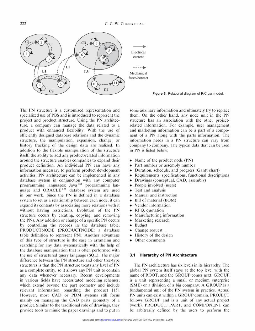
Figure 3 shows a PBS of a simplified R/C (remotecontrol) car model. There are functional interactionsamong components in addition to the physical structureof the model. The binary matrix of the functionalrelationships is shown in Figure 4. Since the model wasbuilt based on the structural diagram from Figure 3,a permutation process is not necessary in this case. Theflow of material is similarly defined in Figure 4, butin this case, there are two types of material flow, i.e.,electronic current and mechanical force.
Figure 4 shows that from Component 1 to 5, thedominant flow is electronic current, while fromComponent 6 to 11, the dominant flow is mechanicalforce. The relational diagram of this interaction is
shown in Figure 5, which shows two types of flowindicated by different types of arrows.
The multiple relationships cannot be representedin a single binary matrix model. The complex, possiblemultiple relationships can be represented in databaserelations (relation: table in a database system) relativelyeasily [14].
3. Product Node Architecture
The design of a dynamic product node (PN) archi-tecture was developed with the intention to simplify theprocess of distributed project and product management.
10000000000111100000000010011000000009001100000008000110000007000011000006000001100005000000110004000000011003000000001102000000000111
1110987654321
10000000000111100000000010011000000009001100000008000110000007000011000006000001100005000000110004000000011003000000001102000000000111
1110987654321
Mechanicalforce/contact
Electroniccurrent/contact
Ele
ctro
nic
curr
ent/
cont
act
Mec
hani
cal
forc
e/co
ntac
t
C1
C2
C3
C4
L1
L2
L3
* C1, C2, C3, and C4 are functional subgroups (subsystems) in modeling* L1, L2, and L3 are the links among the subgroups
Figure 4. Binary matrix of R/C car model.
R/C car
Drivetrain
Frame Exterior
Powerassy
Battery Connector
Controlunits
ServoSpd ctrl
unit
Drivingunit
Motor Gearbox Differential
Wheel
Spoke Tire
Axlehead
Diff.gear
Case
(1) (2) (3) (4) (5) (6) (7)
(8) (9)
(10) (11)
Figure 3. Product structure of an R/C car model.
Product Node Architecture to Provide Structured Flexibility 221
at PURDUE UNIV LIBRARY TSS on November 2, 2009 http://cer.sagepub.comDownloaded from
The PN structure is a customized representation andspecialized use of PBS and is introduced to represent theproject and product structure. Using the PN architec-ture, a company can manage the data related to aproduct with enhanced flexibility. With the use ofefficiently designed database relations and the dynamicstructure, the manipulation, expansion, change, orhistory tracking of the design data are realized. Inaddition to the flexible manipulation of the structureitself, the ability to add any product-related informationaround the structure enables companies to expand theirproduct definition. An individual PN can have anyinformation necessary to perform product developmentactivities. PN architecture can be implemented in anydatabase system in conjunction with any computerprogramming languages; JavaTM programming lan-guage and ORACLETM database system are usedin our work. Since the PN is defined in a databasesystem to set as a relationship between each node, it canexpand its contents by associating more relations with itwithout having restrictions. Evolution of the PNstructure occurs by creating, copying, and removingthe PNs. Any addition or change of a specific PN occursby controlling the records in the database table,PRODUCTNODE (PRODUCTNODE: a databasetable definition to represent PN). Another advantageof this type of structure is the ease in arranging andsearching for any data systematically with the help ofthe database manipulation that is often performed withthe use of structured query language (SQL). The majordifference between the PN structure and other tree-typestructures is that the PN structure treats any level of PNas a complete entity, so it allows any PN unit to containany data whenever necessary. Recent developmentsin various fields have necessitated modeling schemes,which extend beyond the part geometry and includerelevant information regarding the product [15].However, most CAD or PDM systems still focusmainly on managing the CAD parts geometry of aproduct. Similar to the traditional role of drawings, theyprovide tools to mimic the paper drawings and to put in
some auxiliary information and ultimately try to replacethem. On the other hand, any node unit in the PNstructure has an association with the other project-related information. For example, user managementand marketing information can be a part of a compo-nent of a PN along with the parts information. Theinformation needs in a PN structure can vary fromcompany to company. The typical data that can be usedin PN is listed below:
. Name of the product node (PN)
. Part number or assembly number
. Duration, schedule, and progress (Gantt chart)
. Requirements, specifications, functional descriptions
. Drawings (conceptual, CAD, assembly)
. People involved (users)
. Test and analysis
. Manual and instruction
. Bill of material (BOM)
. Vendor information
. RFQ, quotation
. Manufacturing information
. Marketing research
. Budget
. Change request
. History of the design
. Other documents
3.1 Hierarchy of PN Architecture
The PN architecture has six levels in its hierarchy. Theglobal PN system itself stays at the top level with thename of ROOT, and the GROUP comes next. GROUPis a unit representing a small or medium enterprise(SME) or a division of a big company. A GROUP is afundamental unit of the PN system in practice. ActualPN units can exist within a GROUP domain. PROJECTfollows GROUP and is a unit of any actual project(work). PRODUCT, PART, and COMPONENT canbe arbitrarily defined by the users to perform the
3
1
2
4 5
C1
C2
L2L1
96
7C3
10 11
C4
8
L3
Electricalcurrent
Mechanicalforce/contact
Figure 5. Relational diagram of R/C car model.
222 C. C.-W. CHUNG ET AL.
at PURDUE UNIV LIBRARY TSS on November 2, 2009 http://cer.sagepub.comDownloaded from

product design project. The schematic of the overallhierarchy of the PN system is shown in Figure 6.
Users will only see the projects within the GROUPdomain that they are associated with since users do notneed to have system administrator privilege designedto create group and administrators. PN system serverdomain is only ‘ROOT’ for the GROUP domain.Detailed transactions within the GROUP domain willbe explained in the next sections.
4. Types of Product Node
The creator of a PN determines its type. Type allowsusers to know what type of PN they are working on.There are PROJECT, PRODUCT, PART, andCOMPONENT in PN types. Table 1 shows a list ofthe types of PN and their roles. A PN type, PROJECT,is named and treated separately in the system since it isthe starting point of project and it is only parent-PN.Although the structure of a PROJECT-PN is almostidentical to that of the other PN types, it forms the basisof any design activity. An administrator or managerwith privilege can create a PROJECT-PN to initiate aproject.
4.1 Data Definition of Product Node
The PN has multiple attributes and includefield names, primary and foreign keys. The relation,PRODUCTNODE, has basic fields needed sinceother related information is linked to it by the use ofassociation tables (table: different name of relation).
The attributes and definition of the relation,PRODUCTNODE, in the PN system are shown inTable 2. ID is a Primary Key (Primary Key: a unique IDof a database table; often shown with solid underline) ofthe relation, PRODUCTNODE, to make an instance(instance: a record of a database table) of the relationa unique one. Other multiattributes concerning historytracking, and reuse of a PN will be discussed in latersections of this article with implementation examples.
5. Parent–Child Relationship
One of the attributes of a PRODUCTNODE is theForeign Key (Foreign Key: Index to the other table’sPrimary Key), ParentID
�������, to link the current PN to the
Parent-PN. The parent–child relationship forms thebasis of the PN structure. The structure grows from oneparent (i.e., PROJECT-PN) by creating children-PNs (i.e., PRODUCT-PN, PART-PN) underneath.The relationship is shown in Figure 7.
Group domain(SME or a depart of a
large company)
Prj 1
Prod 1 Prod 2 Prod 3
Prt 1 Cmp 1
Cmp 3Cmp 2
Prt 2
Cmp 5Cmp 4
Prj 2
Prod 3
Prt 2
Cmp 5Cmp 4
Prj 3
Create projectsand managers
Groupadministrator
Prj N
PN system server domain
Create group andadministratorsSystem
administrator
Figure 6. Overall hierarchy structure of PN system.
Table 1. Types of product nodes in ‘NODETYPE’.
Node type Role
Project Fundamental unit in PN structure,starting point of any project in acompany (group level)
Product Unit of a product within a projectPart Part, combination of zero to many
componentsComponent A unit component which cannot be
divided any further, leaf node
Product Node Architecture to Provide Structured Flexibility 223
at PURDUE UNIV LIBRARY TSS on November 2, 2009 http://cer.sagepub.comDownloaded from

Among the many types of PN, only PROJECT-PNcan exist without having any Parent-PN associated sincePROJECT-PN is the starting point of any project. In thesystem level (internal logic of the software), GROUPplays the role as the parent of any PROJECT-PN withinthe group. Figure 8 shows the detailed relationshipsbetween parent and child-PNs at the database level. Theforeign key, PID
���, of a child-PN refers to the primary key
ID of a parent-PN.
6. Manipulation of PNs
Dynamic project management entails many changesin the product structure. Based on manipulations(adding, changing, and removing) of the PN structure,the product definition will grow or shrink. After aPROJECT-PN is created by an administrator to initiate
a project at the GROUP domain level, additionalfunctional menus to input other critical information,such as users and tasks, will be available to the usersbased on the privileges given. Creating a PN is the sameas adding one conceptual unit or a physical part in thePN structure. From any location of the PN system,users can create a child-PN of it. With the command tocreate, the PN system will ask the user to input someattributes of the relation, PRODUCTNODE. Name,StartDate, EndDate, NodeType, and Description arethe input needed by the system, and other attributeswill automatically be assigned in the table,PRODUCTNODE. An ID will be assigned with aunique number and the Version will start from 1.0. Afterconfirming the transaction, a new child Node will showup in the PN structure. As shown in Figure 8, theforeign key ParentID
�������will point to the ID of the parent-
PN after the creation.
6.1 History Tracking of PN
Previous design information is a critical resource forcompanies and often differentiates a company with along history from new start-ups. The problem is thata big portion of the company knowledge exists in theheads of company employees and not within a companyrepository. So, as employees leave or retire from thecompany, the design know-how also gets lost. Morethan 50% of designers and manufacturing designers willleave their companies over the next decade [17]. Mostcompanies are trying their best to maintain all theirdesign and related documentation, but in many cases,they fail due to lack of proper tools. PN structureprovides a means to store design-related informationalong with various other functionalities, thus easingthe maintenance of this information for the users.
Table 2. Definition of PRODUCTNODE table.
Field name Definition
ID Node ID, Primary KeyVersion Version of the Node in incremental NumberParentID�������
Parent Node’s ID, Foreign KeyPreviousID���������
ID of a previous version Node, Foreign KeyNodeTypeID�����������
Type of Node, Foreign Key
CurrentFlag Flag to indicate if the Node is thecurrent (latest) one or not. 1 (yes) or 0 (no)
Name Name of the Node, OptionalTimeBuilt The time PN was createdTimeStart Start time of the Node, Duration starting point
given by usersTimeEnd End time of the Node, Duration ending point
given by usersTimeInitiation Time of Initiation of a Node due to a new
versionTimeTermination Time of Termination of the Node due to a
new versionDescription Description of the NodeKeyWord1 Key Word field to assist searchingKeyWord2 Key Word field to assist searching
( ________ ): Primary Key; (�������
): Foreign Key.
PN1
PN2
PN5PN4
ID: Primary key of a PN
PN3
PN6
ID
ID
PID
ID
PID
ID
PID
ID
PID
ID
PIDPN: Product node
PID: Parent PN’s ID: Reference
Figure 8. Product node structure and parent–child relationship.
Parent PN: Can havezero to many PNs as
children PNs
Child PN: Can haveonly one parent node
Child–parent relationship
Figure 7. Parent–child relationship of PNs.
224 C. C.-W. CHUNG ET AL.
at PURDUE UNIV LIBRARY TSS on November 2, 2009 http://cer.sagepub.comDownloaded from

The reasons why companies have to keep a history ofthe design data and related information are listed below:
. Viewing design history
. Reuse of the previous design
. Re-launching of old products [18]
. Retrieval of old information due to mistakes made inthe current design
. Training new employees
. Supporting managerial decision making
There are two ways to track the history of a PN. First,users can select a PN while browsing through thestructure and retrieve the old versions of the Node toview its history. Second, the users can indicate a specifictime to view the structure at that specific time in history.Figure 9 shows the structural change on a portion ofthe PN structure with time. Under Node ‘P,’ five child-Nodes have been generated, one deleted, and twomodified with the progress of time. T1, T2, and T3show the different structures to the users at differentpoints in time. The structure in the history is shownbased on the two attributes, TimeInitiation andTimeTermination.
6.2 Version Control
There are two ways to manage the version of a model.One way is to maintain different versions of the model
as a whole, and the second way is to maintain differentversions of the elements [16]. For a model having manyelements, it is usually not a good option to choose thecriteria of managing versions as a whole system since theamount of data can grow dramatically, especially in adynamic system where the design changes so often. Alsofor a model having a large amount of information, evenif the logic is simple, the size of the data is likely tooverwhelm the storage capacity of the computer systemin a short period of time. The holistic management of aversion can best be used for small individual elements.In the cases when a system rarely changes, managingversions in parts of a system can impose more loads onthe version management system than maintaining thewhole body of individual elements. Nonetheless, fromthe maintenance point of view, it is better to maintainwhole copies of different versions when the capabilityof storage allows. Maintaining versions based on partialchanges is in general more complicated because thesystem has to track the changes according to the versionchanges even at the component level. But for a largemodel having many elements of data within, it isnecessary to have such a system. The PN system is adynamically evolving structure. So it needs to update theversion of each PN when critical changes occur in it. Thearchitecture of the PN structure uses a combination ofboth holistic and partial maintenance of versions of amodel. The PN system applies a holistic maintenanceto the component level changes, and it applies partial
C C1 C2
A
B B1
D
E
P
T1 T2 T3
Deletion of node
Parent node
Creation
Creation
Creation
Creation
Creation Modification
Modification
Axis of time
P
A B D
T1:
P
A B1 C1
T2:
D
P
A B1 C2
T3:
E
Figure 9. Change in the node structure with time under the same parent-PN.
Product Node Architecture to Provide Structured Flexibility 225
at PURDUE UNIV LIBRARY TSS on November 2, 2009 http://cer.sagepub.comDownloaded from

maintenance for content having many subcomponents(sub-PNs or data) within. The data history of any PNshould be maintained based on the version changes.Figure 10 shows the changes in information related to aPN when the version changes. Whenever a PN upgradesits version, the system generates one more instance ofthe associated information based on the new version.In Figure 10, the first version shows a PN created witha user and a file associated with it. The second versionshows the status when the associated user changes; andthe third version shows the record when an associatedfile changes.
6.3 Design Reuses
One of the main advantages which the small andmedium enterprises (SMEs) and division of a bigcompany will get from using the PN structure is thereuse of previous designs. As Figure 11 shows, 80% ofdesign knowledge can be reused in the design process [19].In the context of the PN structure, reuse of previous
design history is equivalent to reusing the previous PNin a current activity. Creating a PN is also equivalent to
creating a child-PN unless it is a PROJECT-PN. Afterfinding an appropriate PN using the search operation,users can then copy this PN as a child of another PN,instead of creating a new one. The procedure of reuse is
Feb. 04
Feb. 01
CF
1.0Version
1000ID
PN Re co rd
TOT
TOI
PN Record
1st version
Feb. 12TOT
Feb. 04TOI
CF
1.1Version
1001ID
PN Record
CF
PN Record
2nd version
NULLTOT
Feb. 12TOI
CF
1.2Version
1002ID
PN Re cordPN Record
New version
………Mfg.DesignDept .LeeJohnName
30033001IDUSER (Table )
………Mfg.DesignDept .LeeJohnName
USER (Table)
………PPT01Doc0 4Name50085004ID
FILE (Table )
………
FILE (Table)
……
True True
True
View
100210011000PN ID
300330033001US ER ID
US ER _P N_ AS SN (T ab le )
……
False
False False
100210011000PN ID
US ER _P N_ AS SN (T ab le )
……
100210011000PN ID
500850045004FI LEID
FI LE_P N_ASSN (T ab le )
……
FILE_PN_ASSN (Table)
3 new record sets generationwith 3 version changes
Figure 10. Changes in associated information based on upgrading versions of a PN.
20%
40%
New partdesign
Complete reuse ofexisting or externally
supplied parts
Slight modificationof existing parts
40%
Figure 11. Design reuse of parts in OEMs.
226 C. C.-W. CHUNG ET AL.
at PURDUE UNIV LIBRARY TSS on November 2, 2009 http://cer.sagepub.comDownloaded from

described in Figure 12. As can be seen from the figure,when a user copies a PN, the system will generate a newPN with a unique ID, and the attribute ParentID
�������of
the new PN will be linked to the ID of the targeting PN(2 in Figure 12). If this PN has children associated withit, they will also be copied together with the copied PN.
The history of the copied PN can always be retrievedfrom the previous one (1 in Figure 12). All theinformation (i.e., database instances or files) associatedwith the reused PN will be duplicated and the new IDwill be changed for the new PN (4 in Figure 12).
7. Management of Contents
7.1 User Management
There are two contradictory issues in product datamanagement concerning the access privilege control ofthe user. It is a well-known fact that transparency andeasy access to product data will boost the understand-ing of the product for all users and will increase theproductivity of the team. In real-world practice, how-ever, most of the design data is company property and,therefore, mostly confidential. But some informationis shared with suppliers on a need basis. When it comesto a multicompany and multiuser project, successful
control between these two conflicting issues is one ofthe key concerns. Hence, providing the means for aprecise control on access to information has beenan important consideration in the design of the PNstructure. The user is one piece of informationassociated with a PN, which has information such asname, email, and the company associated with it. Ingeneral, there are many different types of users whomay use the PN system. For example, in a design teamat a manufacturing company, there is a leader, designteam members, and most likely, a supervisor. In eachdivision or department of a company, there are varioushierarchy-based roles for employees, who all havedifferent authority statuses. Well-defined roles andprivilege management are necessary not only in inter-company collaboration processes but also in intracom-pany processes. There are many users associated witha PN and vice versa. In such a case, creating anassociation table to link those two relations (i.e., USERand PRODUCTNODE) is a general practice. Figure 13shows the relationship between the USER table and thePRODUCTNODE table.
There are six main categories which have been definedto represent different types of users. With a combinationof user types and accessibility to product data, the PNsystem can simulate and generate roles of users similarto those of real-world companies. Administrator (Group
Destination(targeting PN)
Copyingobject
(PN to reuse)
Childrennodes
New PNstructure
1 2 3
PN after reuse
4
Figure 12. Schematic diagram of reusing a product node.
USERPRODUCT
NODEHas HasUSER-NODE
ASSN
: Optional many
ID IDUserID NodeID
: ReferenceFigure 13. ER diagram of user–node (PN) associations.
Product Node Architecture to Provide Structured Flexibility 227
at PURDUE UNIV LIBRARY TSS on November 2, 2009 http://cer.sagepub.comDownloaded from
Administrator) is a user who has all the privileges andcapabilities to control the users and projects in a group.The user types and privileges are described in Table 3.The user types are defined in a database table,USERTYPE.
7.2 File and Document Management
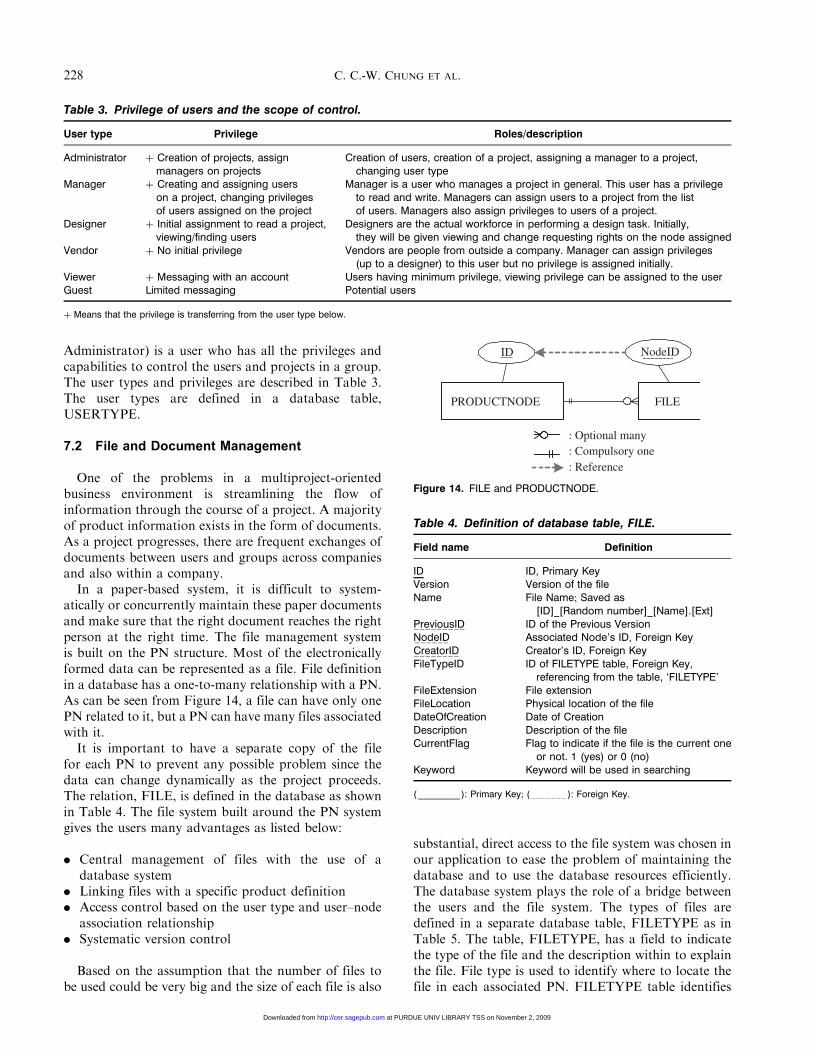
One of the problems in a multiproject-orientedbusiness environment is streamlining the flow ofinformation through the course of a project. A majorityof product information exists in the form of documents.As a project progresses, there are frequent exchanges ofdocuments between users and groups across companiesand also within a company.In a paper-based system, it is difficult to system-
atically or concurrently maintain these paper documentsand make sure that the right document reaches the rightperson at the right time. The file management systemis built on the PN structure. Most of the electronicallyformed data can be represented as a file. File definitionin a database has a one-to-many relationship with a PN.As can be seen from Figure 14, a file can have only onePN related to it, but a PN can have many files associatedwith it.It is important to have a separate copy of the file
for each PN to prevent any possible problem since thedata can change dynamically as the project proceeds.The relation, FILE, is defined in the database as shownin Table 4. The file system built around the PN systemgives the users many advantages as listed below:
. Central management of files with the use of adatabase system
. Linking files with a specific product definition
. Access control based on the user type and user–nodeassociation relationship
. Systematic version control
Based on the assumption that the number of files tobe used could be very big and the size of each file is also
substantial, direct access to the file system was chosen inour application to ease the problem of maintaining thedatabase and to use the database resources efficiently.The database system plays the role of a bridge betweenthe users and the file system. The types of files aredefined in a separate database table, FILETYPE as inTable 5. The table, FILETYPE, has a field to indicatethe type of the file and the description within to explainthe file. File type is used to identify where to locate thefile in each associated PN. FILETYPE table identifies
Table 3. Privilege of users and the scope of control.
User type Privilege Roles/description
Administrator þ Creation of projects, assignmanagers on projects
Creation of users, creation of a project, assigning a manager to a project,changing user type
Manager þ Creating and assigning userson a project, changing privilegesof users assigned on the project
Manager is a user who manages a project in general. This user has a privilegeto read and write. Managers can assign users to a project from the listof users. Managers also assign privileges to users of a project.
Designer þ Initial assignment to read a project,viewing/finding users
Designers are the actual workforce in performing a design task. Initially,they will be given viewing and change requesting rights on the node assigned
Vendor þ No initial privilege Vendors are people from outside a company. Manager can assign privileges(up to a designer) to this user but no privilege is assigned initially.
Viewer þ Messaging with an account Users having minimum privilege, viewing privilege can be assigned to the userGuest Limited messaging Potential users
þ Means that the privilege is transferring from the user type below.
Table 4. Definition of database table, FILE.
Field name Definition
ID ID, Primary KeyVersion Version of the fileName File Name; Saved as
[ID]_[Random number]_[Name].[Ext]PreviousID���������
ID of the Previous VersionNodeID������
Associated Node’s ID, Foreign KeyCreatorID��������
Creator’s ID, Foreign KeyFileTypeID ID of FILETYPE table, Foreign Key,
referencing from the table, ‘FILETYPE’FileExtension File extensionFileLocation Physical location of the fileDateOfCreation Date of CreationDescription Description of the fileCurrentFlag Flag to indicate if the file is the current one
or not. 1 (yes) or 0 (no)Keyword Keyword will be used in searching
( _________ ): Primary Key; (�������
): Foreign Key.
PRODUCTNODE FILE
: Optional many: Compulsory one
ID NodeID
: Reference
Figure 14. FILE and PRODUCTNODE.
228 C. C.-W. CHUNG ET AL.
at PURDUE UNIV LIBRARY TSS on November 2, 2009 http://cer.sagepub.comDownloaded from

the type of file stored in the system. Since mostinformation exists in the form of files, the table indicatesthe kind of information the file has. Based on thereference to the ID of the table, FILETYPE, the systemcan identify the use of the files saved in the PN.
8. Implementation
8.1 Representation of PN
The overall program architecture of the PN system isshown in Figure 15. The prototype implementation wasmade to test the feasibility and the basic operationsnecessary to the PN system architecture. It consists ofthree layers – application layer (front-end), middle layer,and database layer. The information about the PNstructure is retrieved from the database and stored in aneutral Extensible Markup Language (XML) format inthe middle layer. This information is then presented tothe user through the application layer consisting of JavaServer Pages (JSPTM), JavaScriptTM, and Hype-TextMarkup Language (HTML). The application layerhandles all the user interactions and updates its viewaccordingly. The default view of the applicationlayer shows the root node (PROJECT-PN) with thecorresponding node details. The root node can thenbe expanded to view the child-nodes associated withthe project. To get the required information about thechild-nodes, a query is made to the database with the
node ID (i.e., the Project ID) as the query parameter.Subsequently, the information about the child-nodes(i.e., the nodes which have the passed query parameter(Project ID) as its parent ID) is then retrieved from thedatabase. For each such child-node, a query is againmade to the database system to find the nodes at thenext level (i.e., child’s child-node). This recursive querytraverses through the entire database until it reaches theleaf-node (leaf-node: node having no child-node under).This information is made available to the middle layer,where the Microsoft� XML Parser (Microsoft� XMLParser comes with Microsoft� Internet ExplorerTM)puts all the retrieved information into XML format.The application layer uses the node structure in theXML format and then displays it in HTML format asin Figure 16.
8.2 Basic Operation
A child node can be added to an existing node usingthe ‘Add Node’ command as shown in Figure 16. Theuser can fill in the details for the child-node. This willthen be added as a child to the node ‘Drive Train.’ Usingthis ‘Modify’ functionality, the user can make changesto the node details. The user first needs to select theappropriate node on the left side frame and thenproceed to make the changes. The ‘File Management’functionality allows the user to associate files with aparticular node. The files are stored in the server under afolder structure, which reflects the node structure.
9. Conclusions
Various methodologies which deal with the represen-tation of product information and their interactionshave been discussed. Based on an analysis of the existing
GUI interface, tree.jsp,to show a project
node (i.e., RC-CARmodel)
Queries Productinformation
DB
Result-setfirst level productnode (DriveTrain,
frame, exterior,wheels
XMLData
All child node dataretrieved and written
in XML format
Uses MicrosoftXML parser to
convert data intoHTML format
Product node ID for RC-CAR is used as a query
arameter to get information
tree.jsp treeNodeXML.jsp
Recursive queries toDB with IDs of the
subsequentPN entities
Star
t
Figure 15. Basic structure of the PN system.
Table 5. Definition of FILETYPE table.
Field name Definition
ID Primary KeyTypeName File Type
Product Node Architecture to Provide Structured Flexibility 229
at PURDUE UNIV LIBRARY TSS on November 2, 2009 http://cer.sagepub.comDownloaded from

systems, problems arising due to the static structure ofinformation representation as well as non-concurrentoperations have been identified. To address these issues,a new methodology of PN has been introduced.The dynamic structure of the PN system enablesthe synchronization of a project initiation and theactual progress of the project. Database structures of thePN system and the logic of transactions of the use havebeen shown in detail in this work. Manipulation of PN,such as changing the product structure, history tracking,reuse of previous design, file and document manage-ment, and user management show the ‘structuredflexibility’ of the system. The prototype applicationshows the basic functions required by the PN systemand the viability of the system structure.
Acknowledgments
The support of the 21st Century Research andTechnology Fund and the National Science FoundationPartnership for the Innovation Award to PRECISE(Purdue Research and Education Center for Infor-mation in Engineering) is gratefully acknowledged.
References
1. Frank, A., Sellentin, J. and Mitschang, B. (2000).TOGA – A Customizable Service for Data-centricCollaboration, Information Systems, 25(2): 157–176.
2. Prasad, B., Wang, F. and Deng, J. (1997). Towardsa Computer-Supported Cooperative Environment forConcurrent Engineering, Concurrent Engineering: Researchand Applications, 5(3): 233–251.
3. Qiang, L., Zhang, Y.F. and Nee, A.Y.C. (2001).A Distributive and Collaborative Concurrent ProductDesign System through the WWW/Internet, InternationalJournal of Advanced Manufacturing Technology, 17(5):315–322.
4. Miller, E. and Koucky, S. (2002). Market ConsolidationRaises Executive Awareness of PLM, Machine Design,74(14): 56.
5. Lingblom, M. (2001). EDS Forms Unit Devoted to PLMSolutions, Computer Reseller News, 10/8/2001(966): 22.
6. Naumann, T., Vajna, S., Speck, H. and Ende, A. (2002).Relationship Between Process and Product Structures – ANew and Flexible Approach for an Integrated DynamicProcess Management, In: Proceedings of DETC ’02,Montreal, Canada, September 29–October 2.
7. Gane, C. and Sarson, T. (1979). Structured SystemsAnalysis: Tools and Techniques, New York, NY 10019:Improved System Technologies, Inc.
Figure 16. Expanded structure and basic operation view of PN.
230 C. C.-W. CHUNG ET AL.
at PURDUE UNIV LIBRARY TSS on November 2, 2009 http://cer.sagepub.comDownloaded from

8. O’Donnell, F.J., MacCallum, K.J., Hogg, T.D. and Yu, B.(1996). Product Structuring in a Small ManufacturingEnterprise, Computers in Industry, 31(3): 281–292.
9. Szykman, S., Racz, J., Bochenek, C. and Sriram, R.D.(2000). A Web-based System for Design ArtifactModeling, Design Studies, 21(2): 145–165.
10. Gorti, S.R., Gupta, A., Kim, G.J., Sriram, R.D. andWong, A. (1998). An Object-oriented Representation forProduct and Design Processes, Computer Aided Design,28(11): 489–501.
11. Liang, W.Y. and O’Grady, P. (1998). Design with Objects:An Approach to Object-oriented Design, Computer AidedDesign, 30(12): 943–956.
12. Hameri, A.P. and Nitter, P. (2002). Engineering DataManagement through Different Breakdown Structuresin a Large-scale Project, International Journal of ProjectManagement, 20(5): 375–384.
13. Warfield, J.N. (1974). Structuring Complex Systems,Battelle Memorial Institute, Columbus, Ohio.
14. Date, C.J. (2000). An Introduction to Database Systems,Addison Wesley Longman, Inc., Boston, MA.
15. Kumar, V., Burns, D., Dutta, D. and Hoffmann, C.(1999). A Framework for Object Modeling, ComputerAided Design, 31(9): 541–556.
16. Proper, H.A. (1997). Data Schema Design as a SchemaEvolution Process, Data & Knowledge Engineering, 22(2):159–189.
17. Crabb, H.C. (1998). The Virtual Engineer, 21st CenturyProduct Development, New York: SME/ASME Press.
18. Stock, J., Speh, T. and Shear, H. (2002). Many Happy(Product) Returns, Harvard Business Review, pp. 16–18.
19. Rezayat, M. (2000). Knowledge-based ProductDevelopment Using XML and KCs, Computer-AidedDesign, 32(5): 299–309.
20. Prasad, B. (1999). Concurrent Engineering Fundamentals:Integrated Product and Process Organization, Vol. I,New Jersey: Prentice Hall PTR.
21. Prasad, B., Wang, F. and Deng, J. (1998). A ConcurrentWorkflow Management Process for Integrated ProductDevelopment, Journal of Engineering Design, 9(2): 121–135.
Charles Chan-Woo Chung
Dr Chung received his PhDin Mechanical Engineeringfrom the Purdue University.As a graduate student, hewas a NSF/IGERT Fellow. Hereceived his MS from YonseiUniversity, Korea in 1997.His research focus was onRapid Tooling/Prototyping,CAD, Product Informatics,Product/Process Data Model-ing, Knowledge Database
Modeling, Engineering Advisory Systems, and ProductLifecycle Management System Design. Dr Chung iscurrently a Senior Consultant at Samsung Data Systems(SDS) in Korea.
Jun-Ki Choi
Jun-Ki Choi is FredrikAndrews EnvironmentalFellow in the School ofMechanical Engineering atPurdue University. Hereceived his MS degree fromthe University of Michigan,Ann Arbor in 1999. He is aPhD candidate in the Schoolof Mechanical Engineering atPurdue University. His currentareas of research include
Design Methodology, Decision Making Analysis,Design for Environment, Environmental Supply ChainManagement, and Collaborative product/processdesign. His research backgrounds also include machin-ing, manufacturing processes, rapid prototyping, andtooling.
Harshal Patwardhan
Harshal Patwardhanreceived his MS degree inIndustrial Engineering atPurdue University in 2004.He received his BachelorsDegree in MechanicalEngineering from PuneUniversity, India in 2000.His current interests are inthe areas of Product andProcess Development, CostEstimation, Supply Chain
Management, and Logistics. He is currently workingat Alpha Sigma Consulting, LLC at Chicago as aConsultant.
Karthik Ramani
Dr Ramani is a Professorin the School of MechanicalEngineering at PurdueUniversity. He earned hisBTech from the IndianInstitute of Technology,Madras in 1985, an MS fromThe Ohio State University in1987, and a PhD fromStanford University in 1991,all in Mechanical Engineering.He has been awarded the
Dupont Young Faculty Award, the National Science
Product Node Architecture to Provide Structured Flexibility 231
at PURDUE UNIV LIBRARY TSS on November 2, 2009 http://cer.sagepub.comDownloaded from

Foundation Research Initiation Award, the NationalScience Foundation CAREER Award, the RalphTeetor Educational Award from the Society ofAutomotive Engineers, the Outstanding YoungManufacturing Engineer Award from the Society ofManufacturing Engineers, and the Ruth and Joel Spira
Award for Outstanding Contributions to theMechanical Engineering Curriculum. Dr Ramani’scurrent projects are in the area of product and processdesign, information retrieval and management, andrapid tooling for future design and manufacturingsystems.
232 C. C.-W. CHUNG ET AL.
at PURDUE UNIV LIBRARY TSS on November 2, 2009 http://cer.sagepub.comDownloaded from