concrete strength tester (cst) - university of · pdf fileconcrete strength tester (cst) ......
TRANSCRIPT

follow us on Facebook@UWPLATTHTCP
CONCRETE STRENGTH TESTER
(CST)
HIGHWAY TECHNICIAN CERTIFICATION PROGRAMUniversity of Wisconsin-Platteville 049 Ottensman Hall • 1 University Plaza Platteville WI 53818-3099Office phone: 608.342.1545 Fax: 608.342.1982

PREFACE The WisDOT Certified Concrete Strength Tester Course Manual was prepared and developed by the Highway Technician Certification Program (HTCP) staff, the HTCP instructors, and other contributors from the Wisconsin Department of Transportation (WisDOT) and the highway industry. The information contained in this course manual is to be exclusively used to train WisDOT and industry Quality Management Program (QMP) concrete strength testers. The intent of this manual is to provide AASHTO-based training as it applies to the compressive strength cylinder testing procedures. It is the responsibility of the WisDOT Certified Concrete Concrete Strength Tester to follow all current WisDOT specification parameters and procedures in accordance when conducting work assignments for the Wisconsin Department of Transportation.
The WisDOT Certified Concrete Strength Tester course manual was developed with these valuable resources:
(1) AASHTO T 231 Capping Cylindrical Concrete Specimens (2) ASTM C 1231 Use of Unbonded Caps in Determination of Compressive Strength
of Hardened Concrete Cylinders (3) AASHTO T 22 Compressive Strength of Cylindrical Concrete
Specimens(Modified) (4) AASHTO T 24 Obtaining and Testing Drilled Cores and Sawed Beams of
Concrete (5) AASHTO T 97 Flexural Strength of Concrete (Using Simple Beam with Third-Point
Loading) (6) AASHTO T 23 Making and Curing Concrete Test Specimens in the Field
ACKNOWLEDGMENTS The HTCP Portland Cement Concrete Technical Manual Committee members have been instrumental contributors to the contents of this course manual. The committee members are:
Jim Parry - WisDOT Concrete Engineer Kevin McMullen - Wisconsin Concrete Pavement Association Jeff Michalski - WisDOT North Central Region David Kopacz – FHWA-Federal Highway Administration Howard “Buck” Barker – Rettler Corporation Jeff Merten – UW-Platteville
WisDOT Technical Assistance Hotline Representative Russell Frank, WisDOT Concrete & Aggregates Engineer - 608-246-7942

TABLE OF CONTENTS
Course Overview
TOPIC A: AASHTO T 231 – Capping Cylindrical Concrete Specimens
TOPIC B: ASTM C 1231 – Use of Unbonded Caps in Determination of Compressive Strength of Hardened Concrete Cylinders
TOPIC C: AASHTO T 22 – Compressive Strength of Cylindrical Concrete Specimens
TOPIC D: Compressive Strength Fracture Types
TOPIC E: AASHTO T 24 – Obtaining and Testing Drilled Cores and Sawed Beams of Concrete
TOPIC F: AASHTO T 97 - Flexural Strength of Concrete (Using Simple Beam with Third-Point Loading)
TOPIC G: Data Entry
Appendix:
Understanding Concrete Core Testing
NRMCA Publication No. 185
by Bruce A. Suprenant
Field Curing of Beams, Beam Data, Beam Mark
up
QMP Award, Corrections, Course
Evaluation
Lab Exam

8:00 – 8:15 Registration, introduction, course objectives and course syllabus
8:15 – 9:15 AASHTO T 231 – Capping Cylindrical Concrete Specimens
9:15 – 10:00 ASTM C 1231 – Use of Unbonded Caps in Determination of Compressive Strength of Hardened Concrete Cylinders
10:00 – 10:15 Break
10:15 – 11:00 AASHTO T 22 – Compressive Strength of Cylindrical Concrete Specimens
11:00 – 11:15 Compressive Strength Fracture Types, Data Entry
11:30 – 12:30 Lunch
12:30 – 1:30 Laboratory Demonstration of Sulfur Mortar Capping and Compressive Strength Testing
1:30 – 2:00 AASHTO T 24 – Obtaining and Testing Drilled Cores and Sawed Beams of Concrete
2:00 – 2:45 AASHTO T 97 Flexural Strength of Beams
2:45 – 3:30 Laboratory Demonstration of Flexure Strength
3:15 – 3:30 Break
3:30 – 5:00 WRITTEN EXAMINATION
ADJOURN

Course Overview ii
Introduction The Highway Technician Certification Program (HTCP) welcomes you to the Certified Compressive Strength Tester I course. This course requires eight hours of classroom attendance. The course content will cover capping cylindrical specimens, using unbonded (Neoprene) caps in determination of compressive strength of hardened concrete cylinders, and obtaining and testing drilled cores and sawed beams of concrete.
Course Prerequisites
None required. A person may earn 0.8 continuing education units (CEU’s) upon successful completion of this course.
Certification Requirements
The written examination will be limited to a maximum duration of two (2) hours. The written examination will be “open book and open notes” and will consist of true/false questions, multiple-choice questions, and essay problems. A student will be required to obtain a passing score of 70 percent to be certified as a Concrete Strength Technician I.
Recertification Requirements
Recertification is mandatory every three (3) years. The HTCP will send a recertification notice to each certified technician and the firm or agency before the expiration date of the highest certification level(s) of certification obtained. The certified technician must apply for recertification before the expiration date of the highest level(s) obtained. Each certified technician is responsible for obtaining his/her recertification. Recertification may be obtained in one of the following ways:
Complete the next level certification course: A certified technician can obtain recertification by enrolling and successfully completing the next level certification course.
Comprehensive Recertification Exam: Technician can attend the last day of any relevant certification course offered on the course schedule and take the comprehensive recertification exam or come to a remote comprehensive site held throughout the state.
Class at a reduced fee: Opportunity to come back through classroom training to recertify at a reduced fee. A person may earn 0.8 Continuing Education Units (CEUs) upon successful completion of this course.
Revocation/Suspension of Certification Upon written request from any individual, firm, agency, or contractor associated with the HTCP, the HTCP director will provide technical assistance in investigating any alleged report(s) of either certified technician incompetence or act(s) of malfeasance. The HTCP director will then notify WisDOT of the report findings concerning certified technician incompetence or misconduct.

Course Overview ii
Highway Technician Certification Program Goal
The principal goal of the Highway Technician Certification Program (HTCP) is to certify that individuals have demonstrated the abilities to engage in quality control/quality assurance activities in highway work contracted by the Wisconsin Department of Transportation (WisDOT).
Introduction of Course Participants At this time, you will be asked to introduce yourself, company name, years of service to the Portland cement concrete industry, and your present occupational duty.
What do you expect from this Training Course?
This is your opportunity, as a course participant, to ask the course instructor to cover any other topics related to the Concrete Strength Tester I course. Please list and identify topics below:
Duties and Responsibilities of a Certified Concrete Strength Tester I The duties and responsibilities of a Certified Concrete Strength Tester I:
Know how to perform the practice for providing plane surfaces on the ends of freshly
made and hardened cylinders or drilled cores.
Know the calibration frequency and required load rates for cylinder compression testing.
Know the appropriate test methods for obtaining, preparing, and testing drilled cores for axial compression testing.
Know how to apply a compressive axial load to a hardened cylindrical test specimen at a prescribed rate until failure occurs.
Know how to calculate the hardened concrete cylinder compressive strengths and report test data results.
Know the safety, handling, and storage requirements for the equipment.
Know which project personnel to contact to obtain specification requirements, evaluate the test results in relation to these specifications, and report results to the appropriate persons.
Be able to maintain records in an organized manner and document sampling and testing performed and actions taken as a result of sampling and testing required by specification.

Topic A: Capping Cylindrical Concrete Specimens

Topic A: AASHTO T 231 (WisDOT Modified) A-1 Capping Cylindrical Concrete Specimens
Significance and Use ............................................................................. A-2 Equipment ............................................................................................. A-2 Capping Materials .................................................................................. A-2 Neat Hydraulic Cement Paste ................................................................ A-3 High-Strength Gypsum Cement Paste ................................................... A-3 Sulfur Mortar .......................................................................................... A-4 Protection of Specimens after Capping .................................................. A-6 Field-Cured vs. Laboratory-Cured Testing ................................................ A-7

Topic A: AASHTO T 231 (WisDOT Modified) A-2 Capping Cylindrical Concrete Specimens
A.1 Significance and Use This procedure provides plane surfaces on the ends of hardened and freshly-molded concrete cylinders or drilled concrete cores to deliver an even distribution of the force applied by a compression machine to the ends of a cylindrical specimen.
A.2 Equipment
1. Capping Plates shall be at least 1 in. greater than diameter of specimen a. ¼” glass plate, or b. ½ in. machines metal plate, or c. polished plate of granite at least 3 inches thickness
2. 12-inch Carpenter’s Square
3. Alignment Devices or bull’s eye level
4. Melting pot for sulfur mortars and extra Sulfur Mortar material
5. Thermometer (reads to at least 300oF)
6. Exhaust hood
7. Ladle
8. Silicon spray lubricant or mineral oil
9. Cloth if using mineral oil
10. Dead-blow hammer (lead shot in head)
11. 0.002 in. leaf-type feeler gage
12. Machined straight edge
13. Calipers to check dimensions on capping plates
14. Metal implement to find hollow areas
15. Three-gang brass mold with special cover plate
A.3 Capping Materials A.3.1 Three Types of Capping Materials:
1. Neat hydraulic cement paste – Portland or blended cement mixed with water only 2. High-strength gypsum cement paste – white gypsum cement mixed with water
only (“Ultracal” is typically utilized.) 3. Sulfur mortar – ceramic material cast in a molten state that gains strength as it
cools

Topic A: AASHTO T 231 (WisDOT Modified) A-3 Capping Cylindrical Concrete Specimens
A.3.2 Strength and thickness requirements for all three capping materials:
For Normal Strength Concrete: 500 – 7000 psi
1. Minimum Strength of Capping Material a. 5000 psi b. OR cylinder strength if it is greater than 5000 psi
2. Cap Thickness (measured after cylinder has been tested)
a. 0.25 in. (1/4 in.) maximum average b. 0.31 in. (5/16 in.) maximum of any part
If concrete strengths greater than 7000 psi are anticipated, see Table 1 of AASHTO T 231 for strength and thickness requirements of capping materials.
The strength of capping material should be conducted on receipt of new lot or at an interval not to exceed three months. Compressive strength tests of 2 in. cubes performed in accordance with AASHTO T 106 will be used to verify capping material strength.
A.4 Neat Hydraulic Cement Paste
A.4.1 General Requirements
1. A paste made from a mix of water and cements conforming to AASHTO M 85
Types I, II, or III. 2. Conduct qualification tests prior to use for capping to establish relationship
between water-cement ratio and compressive strength of 2-inch cubes. 3. Only acceptable method for capping Freshly Molded Cylinders. 4. This capping method is rarely used.
Optimum consistency is generally produced at the following water cement ratios:
TYPE I & II = 0.32 - 0.36 TYPE III = 0.35 - 0.39
A.4.2 See AASHTO T 231 Sections 5.2 & 6 for mixing and capping procedures
A.5 High-Strength Gypsum Cement Paste
A.5.1 Strength Requirements
1. Optimum water-gypsum cement ratio is generally produced between 0.26 and 0.30. The recommended water-gypsum cement ratio should produce strengths exceeding 5000 psi.

Topic A: AASHTO T 231 (WisDOT Modified) A-4 Capping Cylindrical Concrete Specimens
2. Qualification tests shall be determined for the water-gypsum cement ratio and age required for compressive strength of 2 in. cubes.
A.5.2 Mixing Procedure
1. Mix the next gypsum cement paste at the desired water-gypsum cement ratio
and use the mixture immediately. The mixture will tend to set rapidly.
2. The material is ready to be cast in cubes for strength testing or cast as a cap on a cylindrical specimen or a masonry unit.
A.5.3 Capping Procedure
1. Mix paste and do not exceed water-cement ratio determined from qualification
tests.
2. Place a mound of pre-mixed capping compound on the appropriate capping plate.
3. Lower the specimen, using a bull’s eye level, on top of the cylinder specimen or
guide bar within 1/8 inch in 12 inches.
4. Generally, capping plates may be removed within 45 minutes with Gypsum cement pastes.
A.6 Sulfur Mortar
A.6.1 Strength Requirements
1. Qualification tests shall be performed for compressive strength using 2 inch cubes to determine the relationship of strength to age.
2. Prepare and test specimens using 2-inch
gang cubes and the metal cover conforming to test methods of AASHTO T 106.
3. Sulfur mortar must be allowed to cool at least two hours before testing for
concrete with strength less than 5000 psi. “At least” means a longer cooling time is acceptable.

Topic A: AASHTO T 231 (WisDOT Modified) A-5 Capping Cylindrical Concrete Specimens
4. For concrete strengths greater than 5000 psi, cubes and possibly caps may have to harden at least 16 hours before testing. Qualification tests using cubes can be performed at varying ages to allow a shorter time.
A.6.2 Mixing Procedure and Casting Cubes
1. Warm-up all parts of the testing apparatus to a temperature between 68o to 86oF
(20o to 30oC).
2. Lightly coat the surfaces within contact with sulfur mortar with mineral oil on a cloth or silicon spray.
3. Utilize an exhaust hood when heating molten sulfur mortar to a temperature of
about 265oF (129oC) and stir frequently. (Note: plan ahead as it may take up to four or more hours to melt mortar.)
4. Using a suitable pouring device, quickly fill all three mortar compartments of the
brass cube molds (with special cover plate) until reaching top of filling hole.
5. Wait approximately 15 minutes and refill the three compartments once again to allow for shrinkage during cooling.
6. Once the cubes have cooled sufficiently, carefully
remove them from their molds.
7. Remove oil, sharp edges, and fins from all mortar cubes. Do not remove the knob formed from the filling hole.
8. After two hours, test cubes in compression
machine by AASHTO T 106 and calculate the compressive strength.
A.6.3 Capping Procedure
1. End condition – perpendicular plane through highest point on the uncapped
cylinder shall be less than 1/8 in. (0.125 in.) from any point on the end of the cylinder. If not, cut, lap, or grind the cylinder prior to capping.
2. Prepare sulfur mortar as specified to 265°F and add sulfur mortar materials to
ensure the oldest material in the pot has not been used more than five (5) times. Place sulfur mortar pot underneath exhaust hood.
3. Warm the capping plate to ensure a slow rate of hardening and enable the
production of thin caps.

Topic A: AASHTO T 231 (WisDOT Modified) A-6 Capping Cylindrical Concrete Specimens
4. Lightly apply release agent to the capping plate with mineral oil or silicon spray. Stir sulfur mortar immediately prior to pouring each cap.
5. Ensure cylinder specimens are free from oil or resins and dry at time of capping
to reduce the risk of steam, foam pockets, or air voids forming larger than 1/4 inch (0.25 in.).
6. Then using the vertical device, pour mortar on the surface of the capping plate.
7. Lift the cylinder above the capping plate, being careful not to drop it on capping
plate (could cause severe burns), and contacting the cylinder with the guides, carefully slide the cylinder (pressing against the guide) onto the capping plate. Be careful not to hesitate too long, thick sulfur cylinder caps can cause low measured cylinder strengths.
8. The cylinder should remain on the
capping plate until the sulfur mortar has hardened.
9. Each day, check the planeness of the
caps on at least three specimens representing the start, middle, and end of the run. Use a straight edge and feeler gauge, making a minimum of three measurements at different diameters to ensure that the surfaces are within 0.002 inch.
10. Also, tap surface lightly with a metal implement to see whether surface is solid or
hollow. A coin or other metal instrument works well for identifying holly caps. Caps with hollow voids larger than ¼ in. must be replaced.
11. The cap shall not have gouges, grooves or indentations greater than 0.01 in.
deep or greater than 0.05 in.2 in surface area. A.7 Protection of Specimens After Capping
Maintain moist cured specimens in a moist condition between the completion of capping and time of testing with a double layer of wet burlap. Do not store specimens with gypsum caps immersed in water or for more than four hours in a moist room. Protect plaster caps from dripping water.
For sulfur mortar compounds, allow at least two hours of time upon completion of capping before compression testing. Gypsum cement caps cannot be tested until the following day.

Topic A: AASHTO T 231 (WisDOT Modified) A-7 Capping Cylindrical Concrete Specimens
A.8 Field-Cured vs. Laboratory-Cured Testing Field-Cured Cylinders – test cylinders that are left at the job site for curing should, as nearly as practicable, be maintained in the same manner as the concrete in the structure. This will indicate when supporting forms may be removed, additional construction loads may be imposed, or the structure may be placed in service.
Laboratory-cured cylinders – test cylinders stored on the job site in a temperature range between 60o to 80oF while shielded from the direct rays of the sun and radiant heating devices. Between 24 and 48 hours after casting, transport the specimens to a department-qualified laboratory for standard curing where they are moist-cured at 73 ± 3oF until tested for compressive strength.
The goal of the lab-cured testing is to determine the quality of the concrete mixture without the influence of construction workmanship or environmental conditions on the project site. Field-cured testing attempts to simulate the compressive strength of concrete in the structure. Field-cured test results are not typically used to accept or reject the concrete. Only lab-cured specimens are used to determine if the concrete meets compressive strength specifications. It is important that lab-curing procedures are followed closely.

TOPIC B: Use of Unbonded Caps

TOPIC B: ASTM C 1231 (WisDOT Modified) Use of Unbonded Caps in Determination of Compressive Strength of Hardened Concrete Cylinders
Test Method Summary............................................................................ B-2 Equipment List ........................................................................................ B-2 Equipment and Apparatus ...................................................................... B-2 Test Specimens ...................................................................................... B-3 Unbonded Cap Procedure ...................................................................... B-3 Qualification of Unbonded Capping Systems and Verification of Reuse of Pads ........................................................................................ B-4

TOPIC B: ASTM C 1231 (WisDOT Modified) B-2 Use of Unbonded Caps in Determination of Compressive Strength of Hardened Concrete Cylinders
B.1 Test Method Summary This test method covers requirements for using unbonded caps for compression testing concrete cylinders. The most commonly used material for use in unbonded caps and retaining rings (or retainers) is neoprene and steel respectively. However, the test method allows the use of other materials.
Unbonded caps are not be used for acceptance testing of concrete with compressive strength below 1500 psi or above 12,000 psi.
B.2 Equipment List 1. Two Retaining Rings
2. Elastomeric (neoprene) pads – 50, 60, or 70 durometer hardness
3. 0.20 in. (5 gauge) –diameter heavy wire
4. 0.002 in. leaf-type feeler gage
5. Machined straight edge
6. Calipers to check gouges on retainers
7. 12 in. carpenter’s square modified to fit around a retainer
B.3 Equipment and Apparatus B.3.1 Elastomeric Pads
Elastomeric materials will accommodate surface irregularities in ends of the cylinders. The dimensions of the pad shall be 1/2 in. ± 1/16 in. thick with a diameter not more than 1/16 in. smaller than the inside diameter of the retainer.
Data indicates that 50 durometer pads may be appropriate for cylinder strengths from 1500 psi to 6000 psi. The use of 60 durometer pads is appropriate for 2500 psi 7000 psi. The appropriate strength range for using 70 durometer pads is 4000 psi 12000 psi.

TOPIC B: ASTM C 1231 (WisDOT Modified) B-3 Use of Unbonded Caps in Determination of Compressive Strength of Hardened Concrete Cylinders
B.3.2 Retaining Rings The Retaining Rings are used to restrain the elastomeric pad from excessive lateral spreading as the load is applied. They are made from steel and some made of aluminum alloys have also been found acceptable. Once placed in the rings, the neoprene pads should not fall out when tipped upside-down.
The inside diameter of the retaining rings shall be within 102% to 107% of the diameter of the cylinder. Minimum wall thickness and minimum bearing surface thickness in the ASTM procedure. The outside surfaces of the metal retainer that contact the compression machine bearing blocks shall be machined plane to within a tolerance of 0.002 in free of gouges, or dents larger than 0.01 in. depth or 0.05 in2 surface area. Protrusions are not allowed. These requirements should be regularly checked.
B.4 Test Specimens
Neither end of cylinder specimens shall depart from perpendicularity to the axis by more than 0.5o [approximately equivalent to 1/8” in 12”]. Check cylinder perpendicularity with a small 12" square.
Diameter measurements shall not differ by more than 2%. A minimum of two diameter measurements will be obtained.
Depressions or protrusions shall be plane within 0.20 in. (1/5 in.) under a straight edge measured with a round wire gauge. If the cylinder ends do not meet this tolerance, the cylinder shall not be tested unless irregularities are corrected by sawing or grinding.
B.5 Unbonded Cap Procedure
1. AASHTO states that unbonded caps may be used on either end or both ends of
the specimen during testing. WisDOT has modified the procedure to exclude this option when running compression tests for their projects. To be consistent, the capping procedure should be the same on both ends.
2. Examine pads for excessive wear or damage. Discard the pads if they show
excessive wear or have cracks or splits longer than 3/8 in. regardless of depth.
3. Center unbonded cylinder caps (retainer with pad inserted) on each end of the cylinder.
4. Place the cylinder on the lower bearing block of the testing machine. Carefully
center the cylinder under the upper spherically-seated bearing block.

TOPIC B: ASTM C 1231 (WisDOT Modified) B-4 Use of Unbonded Caps in Determination of Compressive Strength of Hardened Concrete Cylinders
5. While bringing the retainer in contact with the upper block, rotate the upper bearing block gently to align it parallel to the retainer for uniform contact.
6. After a load has been applied, but not more than 10% of the anticipated failure
load: a. Check to see that the cylinder is vertical in the machine to a tolerance of
not more than 1/8 in. in 12 in.
b. Check that the cylinder is centered in both of the retaining rings.
c. A pause in applying the load to perform these checks is permissible, but not required.
d. If these requirements are not met: release the load, realign the cylinder or retaining rings and reapply the load performing this check again.
7. Complete load application as specified in AASHTO T 22 making sure the test is
run until complete failure has occurred.
8. Neoprene caps may cause a cylinder to rupture more intensely than cylinders tested using sulfur-mortar caps. A protective cage on the compression machine will enhance safety.
9. Each neoprene cap shall not be used to test more than 100 cylinders. It’s a good
idea to turn the pads over at 50 uses. B.6 Qualification of Unbonded Capping Systems and Verification of Reuse of Pads
The maximum number of reuses of a pad is 100 unless the user of the pads demonstrates the pad to be acceptable through ASTM C1231.
Many reusable caps are manufactured from materials other than neoprene and Retaining Rings of metals other steel. Verification tests outlined in ASTM C1231 should be performed to confirm that the pads are satisfactory for compression testing. Many laboratories find this is not economical to do.

Topic C: Compressive Strength of Cylindrical Concrete Specimens

Topic C: AASHTO T 22 (WisDOT Modified) C-1 Compressive Strength of Cylindrical Concrete Specimens
Test Method Summary ........................................................................... C-2 Equipment ............................................................................................. C-2 Compression Testing Machine Apparatus ............................................. C-2 Verification of Calibration ...................................................................... C-2 Bearing Blocks ....................................................................................... C-3 Bottom Bearing Blocks ........................................................................... C-3 Upper (Spherically Seated) Bearing Block ............................................. C-3 Centering Cylinder Specimen ................................................................ C-3 Load Indication ...................................................................................... C-4 Cylindrical Specimens ............................................................................ C-4 Calculation of Concrete Cylindrical Specimen Strength .......................... C-5 Cylinder Compression Procedure .......................................................... C-5 Compressive Strength Calculations ....................................................... C-6 Formulas................................................................................................. C-6 Report .................................................................................................... C-6 Student Problem ..................................................................................... C-7 Rate of Loading Calculation .................................................................... C-8 Student Problem Answer......................................................................... C-9 Blank Worksheets can be found at the end of this Topic.

Topic C: AASHTO T 22 (WisDOT Modified) C-2 Compressive Strength of Cylindrical Concrete Specimens
C.1 Test Method Summary This test method consists of applying a compressive axial load to molded cylinder specimens or cores at a rate that is within a prescribed range until failure occurs. The compressive strength of the cylinder specimen is calculated by dividing the maximum load attained during the test procedure by the cross-sectional area of the specimen. This test procedure is limited to concrete having a unit weight in excess of 50 lb/ft3.
C.2 Equipment
1. Compression testing machine - rate of loading 35 ± 7 psi/sec
2. Calipers with 3.5 in. long jaws
3. Ruler to measure length to 0.1” increments
4. Stopwatch
5. Cleaning brush or cloth
6. Machined straight edge
7. Water Storage Tank or Moist-cure Room
8. Hydrated lime
9. Recording thermometer
C.3 Compression Testing Machine This testing machine must apply the load continuously without shock. For compression testing machines of either screw type or hydraulic-operated machines, the load should be applied at a rate of movement on the specimen within a range of 35 ± 7 psi/s. The designated rate of movement shall be maintained at least during the latter half of the anticipated loading range.
C.4 Verification of Calibration Calibration of a compression testing machine must be verified at a 12 month interval (WisDOT Modified) in accordance with AASHTO T 67. The accuracy of the load must be within 1.0% for any value displayed within the verified loading range.

Topic C: AASHTO T 22 (WisDOT Modified) C-3 Compressive Strength of Cylindrical Concrete Specimens
Diameter of Test Specimens, in.
Maximum Diameter of Bearing Face, in.
2 4 3 5 4 6.5 6 10 8 11
C.5 Bearing Blocks
The compression machine shall be equipped with two steel bearing blocks, upper and lower, with hardened surfaces. Bearing faces of the blocks shall have a minimum dimension of at least 3% greater than the diameter of the specimen to be tested.
The bearing surface must be within planeness of 0.001 in. in any 6 inches of blocks 6 inches in diameter or larger or by more than 0.001 inches in the diameter of any smaller block. New blocks shall be manufactured within one half of this tolerance.
C.6 Bottom Bearing Blocks
The bottom bearing block may be fastened to the platen of the testing machine. The horizontal dimension shall be at least 3% greater than the diameter of the specimen to be tested. The top and bottom surfaces must be parallel to each other. The bottom block shall be at least 1 in. thick when new and at least 0.9 in. thick after any resurfacing operation.
C.7 Upper (Spherically Seated) Bearing Block
The maximum diameter of the upper bearing block bearing face for a 6 in. diameter of test specimens is 10 in. Square bearing surfaces are permissible, provided the diameter of the largest possible inscribed circle does not exceed the above diameter.
C.8 Centering Cylinder Specimen
Final centering must be made in reference to the upper spherical block. When the lower bearing block is used to assist in centering the cylinder specimen, the center of concentric rings must be directly below the center of the spherical head.

Topic C: AASHTO T 22 (WisDOT Modified) C-4 Compressive Strength of Cylindrical Concrete Specimens
C.9 Load Indication If a load dial is used on a compression-testing machine, the dial should be on a graduated scale that can be read to the nearest 0.1% of the full scale. The scale should include a graduation line equal to zero and be so numbered. The dial pointer shall be long enough to reach the graduation markings.
Each dial should be easily accessible so the zero adjustment may be made easily and indicate within 1% accuracy the maximum load applied to the specimen.
If the compression testing machine is supplied with a numerical display, then the display must be large enough to be easily read.
C.10 Cylindrical Specimens
The ends of the cylindrical specimens should not be off by more than 0.5o
[approximately 1/8 inch in 12 inches]. The ends of compression test specimens that are not within planeness shall be capped in accordance with AASHTO T 231, sawed, or ground to meet that tolerance.
Cylindrical specimens shall not be tested if any individual diameter of the same cylinder is more than 2%. This may be caused by single use molds that are damaged or deformed during manufacturing.
The diameter used to calculate the cross-sectional area of the test specimen shall be determined to the nearest 0.01 in. by averaging two diameters measured at right angles to each other at mid height of the specimen.
Measure the diameter of each cylinder tested.

Topic C: AASHTO T 22 (WisDOT Modified) C-5 Compressive Strength of Cylindrical Concrete Specimens
The length of the cylinder shall be measured to the nearest 0.05 inch diameter when the length to diameter ratio is less than 1.8 or more than 2.2.
C.11 Calculation of Concrete Cylindrical Specimen Strength The diameter used to calculate the cross-sectional area of the test specimen shall be determined to the nearest 0.01 in. by averaging two diameters measured at right angles to each other at mid-height of the specimen.
C.12 Cylinder Compression Procedure
1. AASHTO M 201 outlines procedures for maintaining moist storage rooms and water storage tanks.
2. The compression test of moist-cured specimens shall be made as soon as
possible after removal from moist storage.
3. Test specimens shall be kept moist by any convenient method during the period between removal from moist storage and testing. They shall be tested in the moist condition.
4. All test specimens for a given test age shall be broken within the permissible
time allowances (seven day test age within six hours and for 28 days within 20 hours).
5. Wipe clean the surfaces of both lower and upper bearing surfaces. Place the
specimen on the lower bearing plate and center specimen directly under upper bearing block.
6. Apply the rate of loading continuously and without shock. During the application
of the first half of the test load, the rate may be at a higher rate up to one-half of the anticipated load.
7. Loads shall be applied at the specified loading rates for screw and hydraulically-
operated machines during the second half of the anticipated loading.
Example hydraulic rate of movement calculation for a 6” x 12” cylinder:
28 lbs sq.in. sec
42 lbs sq.in. sec.
x 28.27 sq.in.792 lbs
sec
x 28.27 sq.in.1,187 lbs
sec
Note: 28.27 sq.in. is the calculated cross-sectional area of a 6.00” dia. concrete cylinder.

Topic C: AASHTO T 22 (WisDOT Modified) C-6 Compressive Strength of Cylindrical Concrete Specimens
8. Apply the load until the specimen fails and record the maximum load carried by the specimen during the test procedure. If the loading rate is too fast, the test result may be erroneously high. Note the type of test failure and the appearance of the concrete.
C.13 Compressive Strength Calculation Calculate the compressive strength of the cylindrical specimen by dividing the maximum load applied to the test specimen and by the average cross-sectional area. Round off the results to the nearest 10 psi.
C.14 Formulas
Average Diameter D1 D2
2
Area = D2 or = R2 = 3.14 or use a calculator key.
4 Compressive Strength = Maximum Load
Ave. Cross-sectional Area NOTE: One pass/fail test result is the average of two compression tests. The CST technician shall round the individual test results to the nearest whole number. Then round the average of two tests to the nearest 10 psi for the pass/fail test.
C.15 Report
The report should include:
Specimen identification number Diameter (and length if outside 1.8 to 2.2 x diameter) Cross-sectional area Age of specimen Date of test* Time of test* Rate of loading* Maximum load* Compressive strength calculated to 10 psi (per AASHTO T22) Type of fracture, if other than the usual cone Defects in either specimen or caps
*AASHTO specifies the testing machine must be capable of automatically recording these four items.

Topic C: AASHTO T 22 (WisDOT Modified) C-7 Compressive Strength of Cylindrical Concrete Specimens
C.15 Student Problem:
Compressive Strength Example
The diameters of a concrete cylinder specimen are measured as 6.04” and 5.98” and the maximum load sustained in a compression test is 99,000 pounds.
a) Calculate the average diameter.
b) Calculate the cross-sectional area.
c) Calculate the compressive strength of the cylinder.
Solution can be found on the Page C-9 of this Topic.

Topic C: AASHTO T 22 (WisDOT Modified) C-8 Compressive Strength of Cylindrical Concrete Specimens
C.16 Rate of Loading Calculation
120000
100000
Peak Load = 99,000 lbs
80000
Load, lbs
60000
40000
20000
0
0 10 20 30 40 50 60 70 80 90
Time, sec
For each 28-day compressive strength test used to determine if specifications are met the rate of loading shall be calculated. Simply providing a graph of Load vs. Time is not enough. It must be determine if the rate of loading 35 ± 7 psi/sec has been met.
1. The rate of loading is the slope of the line on a Load vs. Time plot.
Rate of Loading = (Increase in Load) (Increase in Time) X (Cross-sectional Area)
2. Select two points on the line where it’s easy to pick numbers off the chart.
a. At 20 seconds the load was 40,000 pounds. b. At 60 seconds the load was 80,000 pounds.
3. Rate of Loading = (80,000 – 40,000 lbs) = 40,000 lbs = 35.3 psi
(60 – 20 sec) X (28.35 sq in) 40 sec X 28.35 sq in sec 4. Is it a valid test based on rate of loading? Yes.

Topic C: AASHTO T 22 (WisDOT Modified) C-9 Compressive Strength of Cylindrical Concrete Specimens
Student Problem: Answer
Compressive Strength Example
The diameters of a concrete cylinder specimen are measured as 6.04” and 5.98”, and the maximum load sustained in a compression test is 99,000 pounds.
a) Calculate average diameter.
Average Diameter D1 D2
2
Average Diameter = 6.04 + 5.98 2
Average Diameter = 6.01 (Note: WisDOT always rounds number next to “5” up.)
b) Calculate the cross-sectional area
Area = D2
4
Area = (6.01)2
4
Area = 28.35 sq. inches
c) Calculate the compressive strength of the cylinder.
Compressive Strength = Maximum Load Ave. Cross-sectional Area
Compressive Strength - 99,000 lbs.
28.35 sq. inches
Compressive Strength = 3492.1 psi
Report Compressive Strength = 3490 psi
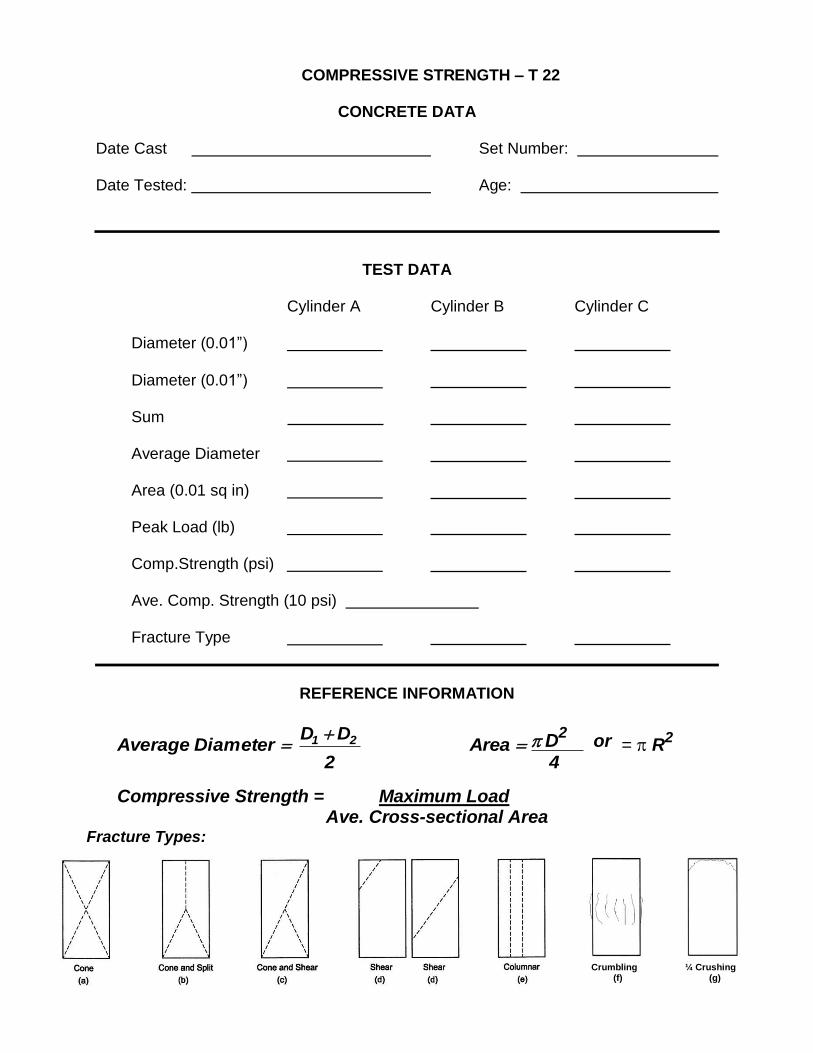
COMPRESSIVE STRENGTH – T 22
CONCRETE DATA
Date Cast Set Number:
Date Tested: Age:
TEST DATA
Cylinder A Cylinder B Cylinder C
Diameter (0.01”)
Diameter (0.01”)
Sum
Average Diameter
Area (0.01 sq in)
Peak Load (lb)
Comp.Strength (psi)
Ave. Comp. Strength (10 psi)
Fracture Type
REFERENCE INFORMATION
Average Diameter D1 D2 Area D
2 or = R2
2 4
Compressive Strength = Maximum Load Ave. Cross-sectional Area
Fracture Types:
Crumbling ¼ Crushing (f) (g)

Topic D: Compression Fracture Types
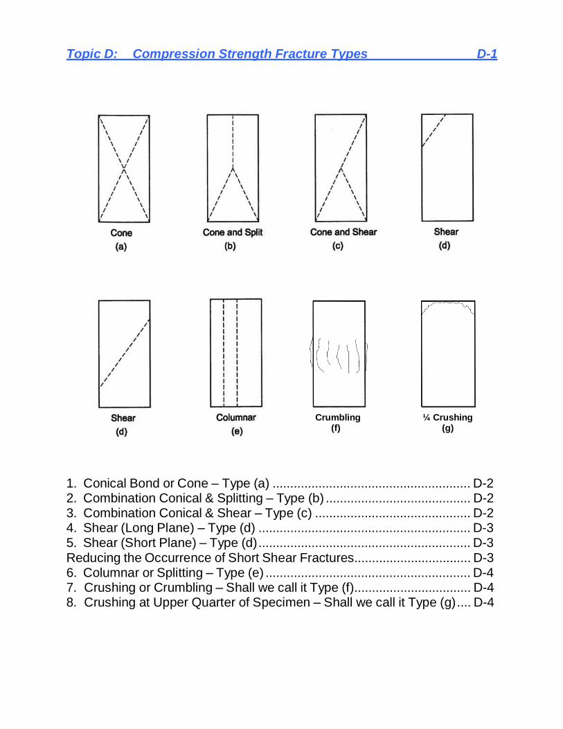
Topic D: Compression Strength Fracture Types D-1
Crumbling ¼ Crushing
(f) (g)
1. Conical Bond or Cone – Type (a) ........................................................ D-2 2. Combination Conical & Splitting – Type (b) ......................................... D-2 3. Combination Conical & Shear – Type (c) ............................................ D-2 4. Shear (Long Plane) – Type (d) ............................................................ D-3 5. Shear (Short Plane) – Type (d) ............................................................ D-3 Reducing the Occurrence of Short Shear Fractures................................. D-3 6. Columnar or Splitting – Type (e) .......................................................... D-4 7. Crushing or Crumbling – Shall we call it Type (f)................................. D-4 8. Crushing at Upper Quarter of Specimen – Shall we call it Type (g).... D-4

Topic D: Compression Strength Fracture Types D-2
D.1 Types of Fractures in Concrete Test Cylinders 1. Conical Bond or Cone – Type (a)
This is by far the most common type of failure. There may be some fractured aggregate particles along the shear faces, but most of the failure occurs at the contact surface of the mortar and aggregates.
2. Combination Conical & Splitting – Type (b) This is typical of the many combinations of the various types of failure that may occur. The fracture may, or may not, be significant and the cylinder should, therefore, be visually examined.
3. Combination Conical & Shear – Type (c)
This is typical of the many combinations of the various types of failure that may occur. The fracture may, or may not, be significant and the cylinder should, therefore, be visually examined for a possible defect such as a large piece of aggregate or a large void perhaps from rodding.

Topic D: Compression Strength Fracture Types D-3
4. Shear (Long Plane) – Type (d) The fracture plane is usually on about a 60-degree angle with the horizontal. This type of failure is common with high strength concretes where failure is more or less instantaneous rather than a gradual crushing. Like Type c above, the cylinder be visually examined for a possible defect
5. Shear (Short Plane) – Type (d)
This type of fracture also usually occurs on a 60-degree plane and is more common with high strength concretes. It differs from number four in that it is restricted to a portion of the cylinder. One end of the fracture intersect the end of the cylinder with is fully supported by the platen. A fracture of this type may indicate a faulty specimen or cap, uneven loading across the end of the cylinder or splitting when unbonded caps are used, particularly with test results less than 5000 psi. The cylinder and caps should, therefore, be carefully examined for defects, as the compressive strength may not be representative of the concrete in the structure.
Reducing the Occurrence of Short Shear Fractures 1. Smooth trowel cylinder when casting. 2. Prevent concave or out-of-round end.
3. Be conscious of using sulfur mortar capping methods when specimen end conditions exceed 0.5o.
4. Limit the number of pad uses to C 1231 specifications 5. Do not use nicked or warped retaining cups
6. Rotate spherical-seated bearing block as specimen contacts cap to provide a uniform load.
7. Check alignment of specimen at approximately 10% of anticipated load. 8. Annually dismantle, clean, and lightly lubricate (SAE 10) spherical seat on upper
bearing block. 9. Do not allow water from cylinders to migrate under pads in lower retainer. 10. Consider using cornstarch or talcum powder on pads and cylinder ends. 11. Run test until cylinder has completely failed.

Topic D: Compression Strength Fracture Types D-4
6. Columnar or Splitting – Type (e) This type of failure is generally associated with relatively weak concrete if barreling of the cylinder is noted. Ho we ve r , i n h i gh s t r e n g t h co n c re t e , t h i s f ailure occurs throughout the length of the specimen without the formation of any definite angled shear plane or cone.
7. Crushing or Crumbling: Shall we call it – Type (f)?
This is typical of weak concrete. It is similar to Type 6 fracture except the bond is so poor that the concrete crumbles over the entire cross-section of the cylinder. It may also be the result of poor quality aggregate, segregation of aggregate, or void spaces at the point of fracture. Loose aggregate particles and the ability to break off pieces of the concrete in hand indicate weak concrete. A defect in the aggregate or in casting of the cylinder will be rather obvious. It takes a mechanical defect of considerable magnitude to seriously affect the test result, however.
8. Crushing at Upper Quarter of Specimen: Shall we call it – Type (g)?
This type of failure normally indicates a defect in the specimen or the cap. It is a common result when the concrete c y l i n d e r was frozen or shows excessive carbonation (indicated by light colored chalky deposits on the top of the surface of the specimen, usually in the form of small dome-like projections). It may also be the result of damage to the cylinder before testing or a weak or otherwise defective cap. The cylinder should be closely inspected after testing to determine whether any defects are evident. Failures of this type may have compressive strengths that are not representative of the concrete in the structure and the defect should, therefore, be noted.

TOPIC E: AASHTO T 24 (WisDOT Modified)

TOPIC E: AASHTO T 24 (WisDOT Modified) E-1 Obtaining and Testing Drilled Cores and Sawed Beams of Concrete
Test Method Summary............................................................................ E-2 Equipment List ........................................................................................ E-2 Sampling ................................................................................................ E-2 Core Drilling ............................................................................................ E-2 Length of Drilled Core Specimens for Pavement Thickness .................... E-2 Compressive Strength of Drilled Cores ................................................... E-3

TOPIC E: AASHTO T 24 (WisDOT Modified) E-2 Obtaining and Testing Drilled Cores and Sawed Beams of Concrete
E.1 Test Method Summary
This test method covers obtaining, preparing, and testing: (1) cores drilled from concrete for length or compressive strength determinations, and (2) beams sawed from concrete for flexural determinations.
E.2 Equipment List
1. Core Drill – Used to obtain cylindrical core specimens.
2. Saw – Used to cut beam specimens to size for flexural tests.
E.3 Sampling A sample must not be extracted until concrete becomes hard enough not to disturb the bond between the mortar and the aggregates. As a general rule, concrete should not be removed until being cured for 14 calendar days. Discard the sample if it displays abnormal defects or was damaged during the sampling and extraction process. Also, samples containing embedded reinforcement for determining compressive strength may cause inconsistent compressive test values. Embedded reinforcement should be avoided if possible to prevent inaccurate compressive strengths.
E.4 Core Drilling Any core specimen taken perpendicular to the bed of concrete should be taken from the middle of the unit when possible. Avoid coring samples near formed joints or obvious edges.
E.5 Length of Drilled Core Specimens for Pavement Thickness
1. If the core length only is measured to document pavement thickness, then the
minimum diameter of the core shall be 3.70 in.
2. The procedure for length determination should be measured in accordance with AASHTO T 148.

TOPIC E: AASHTO T 24 (WisDOT Modified) E-3 Obtaining and Testing Drilled Cores and Sawed Beams of Concrete
E.6 Compressive Strength of Drilled Cores
1. Test Specimens The diameter of core specimens for determination of compressive strength should be at least two times the nominal maximum size of the coarse aggregate in the core sample but no less than 3.75 in.
2. Specimen Length divided by Diameter (L/D) after Capping (See AASHTO T 22 for
additional details): a. The preferred L/D is between 1.9 to 2.1. b. No correction is required for a L/D greater than 1.75. c. L/D of 1.00 to 1.75 requires a strength correction factor be applied to the
metered compressive strength as outlined in T 22. d. A core shorter than L/D = 1.00 before capping shall not be tested. e. Cores with a L/D larger than 2.1 diameters after capping shall be shortened.
3. End Preparation
Ends of the core specimens for compression must be smooth, perpendicular to the longitudinal axis, and the same diameter as the body.
End preparation should be made if: a. Projections extend more than 0.2 in. above end surfaces. b. End Surfaces shall not depart from perpendicularity to the axis by a
slope of more than 1 to 0.3 times the cylinder’s average diameter c. Diameters of ends differ by more than 0.1 in. from the average diameter.
4. Moisture Conditioning
a. After extracting core from concrete, wipe off excess drilling water and allow the core’s surface to dry.
b. No later than 1 hour after drilling, seal the cores in individual plastic bags or nonabsorbent containers.
c. Protect the bagged cores from moisture loss due to heat or sunlight. d. Keep the cores sealed from moisture loss until no more than 2 hours prior to
testing when end preparation is performed. e. Test the cores within 7 days after coring.
5. Capping
Capping shall be performed according to either AASHTO T 231 or ASTM C1231.
6. Length for Compression Testing Length shall be measured to the nearest 0.1 in. This length should be used to compute the length-to-diameter ratio.

TOPIC E: AASHTO T 24 (WisDOT Modified) E-4 Obtaining and Testing Drilled Cores and Sawed Beams of Concrete
7. Diameter Measurement
a. The diameter should be measured to the nearest 0.01 in. whenever possible, but at least to 0.1 in. Take two measurements at right angles to each other at mid height.
b. Report the average core diameter to the nearest 0.01 in. if the difference in core diameters does not exceed 2 % of their average, otherwise report to the nearest 0.05 in.
8. Testing Conduct the testing of the specimen in accordance with the test provisions of Test Method T 22.
9. Calculation
a. Calculate the compressive strength of each specimen using the computed cross- sectional area based on the average diameter of the specimen. If the length-to- diameter ratio of the specimen falls between 1.75 and 2.10, no correction is necessary. Refer to the AASHTO T 24 table below.
Ratio of Length of Cylinder
to Diameter I/d
Strength Correction Factor *
1.75 0.98
1.50 0.96
1.25 0.93
1.00 0.87
*These correction factors apply to lightweight concrete weighing between 100 and 120 lb/ft
3 and to normal weight concrete. They are applicable to concrete dry or soaked at
the time of loading. Values not given in the table shall be determined by interpolation. The correction factors are applicable for nominal concrete strengths from 2000 to 6000 psi. (Correction factors depend on various conditions such as strength and elastic moduli. Average values are given in the table.)
b. Compressive Strength is calculated to the nearest 10 psi when the core
diameter is measured to the nearest 0.01 in. If the condition of the core prevents measuring the diameter accurately, measure it to 0.1 in. increment and round the results to the nearest 50 psi.

TOPIC E: AASHTO T 24 (WisDOT Modified) E-5 Obtaining and Testing Drilled Cores and Sawed Beams of Concrete
10. Report
The report should include: a. Length of test specimen after capping. b. Diameter of the specimen c. Length to Diameter Ratio d. Measured Peak Load e. Average cross-sectional area f. Measured Compressive Strength g. Correction Factor or “Not Applicable” h. Corrected Compressive Strength i. Direction of load application with respect to horizontal plane. j. Moisture condition at time of testing whether saturated or air-dried. k. Nominal maximum of concrete aggregate.
11. ACI 318 Evaluation of Low Strength Test Results:
a. 85% average of 3 cores. If the specified strength is 4000 psi, then this average is required to exceed 3000 psi.
b. 75% minimum per core – each core must be greater than 3000 psi.
E.7 Flexural Strength of Sawed Beams
1. Test Specimen
A beam specimen for the determination of flexural strength shall, in general, have a cross section of 6 by 6 in. The specimen shall be at least 21 in. in length.
2. Moisture Conditioning
The lab curing of beams is the same curing applied to compressive strength core specimens used for acceptance testing.
3. Testing and Reporting
Test and report specimens in accordance with AASHTO T 97.

Topic F: Flexural Strength F-1
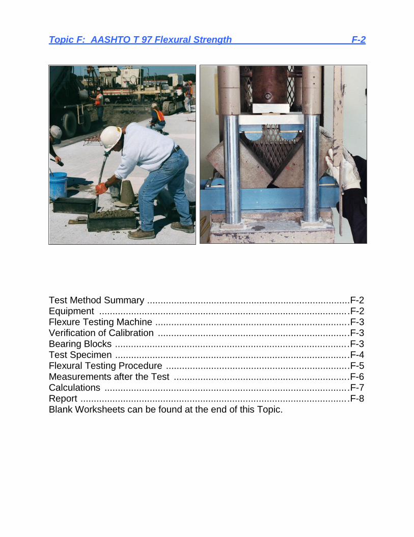
Topic F: AASHTO T 97 Flexural Strength F-2
Test Method Summary ............................................................................F-2 Equipment ..............................................................................................F-2 Flexure Testing Machine .........................................................................F-3 Verification of Calibration ........................................................................F-3 Bearing Blocks ........................................................................................F-3 Test Specimen ........................................................................................F-4 Flexural Testing Procedure .....................................................................F-5 Measurements after the Test ..................................................................F-6 Calculations ............................................................................................F-7 Report .....................................................................................................F-8 Blank Worksheets can be found at the end of this Topic.

Topic F: AASHTO T 97 Flexural Strength F-3
F.1 Test Method Summary This procedure covers determination of the flexural strength of concrete specimens in accordance with AASHTO T 97 using two load-applying blocks placed at the third points of a simply supported concrete beam. This specimen should be molded, cured, and stored according to AASHTO T 23.
Background Information regarding Flexure Testing:
Commonly performed on projects involving Airport Runways/Taxiways. Currently only used only on WisDOT pilot projects. More applicable to pavement design than compression testing.
F.2 Equipment
1. Testing machine with third-point flexural loading apparatus
- rate of loading 125 to 175 psi/min
2. Leaf-type feeler gauges: 0.002 in., 0.004 in., and 0.015 in.
3. Machined straight edge
4. Four Leather shims: ¼ in. thick by 1 to 2 in. wide & as long as specimen is wide
5. Calipers
6. Ruler to measure length to 0.1” increments
7. Stopwatch
8. Small 12” carpenter’s square
9. Magic Marker
10. Water spray bottle or Wet burlap
11. Water Storage Tank or Moist-cure Room
12. Hydrated lime
13. Recording thermometer

Topic F: AASHTO T 97 Flexural Strength F-4
F.3 Flexure Testing Machine This testing machine must apply the load continuously without shock. Although hydraulic machines are mostly used, hand operated machines that can apply a continuous load at a rate of movement within a range of 125 to 175 psi/minute are acceptable. Standard compression machines can be fitted with the bearing blocks used for this testing.
F.4 Verification of Calibration Calibration of the testing machine used for flexure testing must be verified at a 12 month interval (WisDOT Modified) in accordance with AASHTO T 67. The accuracy of the load must be within 1.0% for any value displayed within the verified loading range.
F.5 Bearing Blocks
The flexure machine shall be equipped with four steel bearing blocks, two upper load applying blocks, and two lower support blocks. The distance between the load applying blocks and between the support blocks shall be maintained within 0.05 in. The jig containing the support blocks may be fastened to the testing machine. Lower jigs are not usually fastened to the machine.
The bearing surface must be within planeness of 0.002 in. in any 6 inches of blocks.

Topic F: AASHTO T 97 Flexural Strength F-5
F.6 Test Specimen The most common beams cast for flexure testing is 6” by 6” by 21” long made in accordance with AASHTO T 23. Each specimen should be molded, cured, and stored according to AASHTO T 23.
The span length between the lower support blocks shall be within 2% of three times the depth of the beam. The specimen surfaces must be smooth and free of scars, indentations, holes or inscribed marks.
Turn the specimen on its side with respect to molding when preparing to perform the test. Mark the bottom 1st.
1. Though not required by AASHTO, WisDOT has modified the procedure to include
marking the specimen using a magic marker in a minimum of four locations: a. Once for each of the two load-applying blocks and once for each of the
two support blocks. b. These marks will help when centering the specimen in the testing
machine. 2. Four optional magic marker lines are recommended:
a. Two lines defining the center third of the tension (bottom) surface. b. Two lines marking 5% outside the middle third of the tension surface. c. These marks will aid in identifying the correct formula to use when
calculating test results.
3. Also place four tick marks on each side of the beam at the bearing block location.
Marks on Top of Beam:
Marks on Bottom of Beam:

Topic F: AASHTO T 97 Flexural Strength F-6
F.7 Flexural Testing Procedure
1. AASHTO M 201 outlines procedures for maintaining moist storage rooms and water storage tanks. Concrete beams should be lab-cured in the same fashion as concrete cylinders.
a. Beams should be stood on end in water tanks or moist storage. b. Beams kept in moist-cure rooms shall be placed in a water tank for a
minimum of 20 hours prior to testing (See AASHTO T 23).
2. The flexure test of moist-cured specimens shall be performed as soon as possible after removal from moist storage.
3. Test specimens shall be kept moist by any convenient method during the period
between removal from moist storage and testing. They shall be tested in the moist condition. A water spray bottle is suggested to mist the sample if necessary to keep it moist.
4. After centering the specimen and the loading system in relation to the applied
force, apply a load of 3 to 6% of the anticipated ultimate load to provide a snug contact between the specimen and the blocks.
5. Check for gaps between the specimen and all four bearing blocks.
a. Use a 0.004” leaf-type feeler gauge to search for a 1” or larger gap.
b. If no gap is found, continue the test using this setup.
c. If a ≥1” gap is found, use a 0.015” leaf-type feeler gauge to search for a 1” or larger gap.
d. If no gap is found, release the load, place one shim under all four bearing blocks and continue the test.
e. If a ≥1” gap is found, grind or cap the specimen before performing the test.
f. Try to minimize grinding the specimen. It might be helpful to use a Carborundum Stone (mason’s stone) on the top lip of the specimen at the time of demolding.
g. Capping is typically done using high strength gypsum cement.

Topic F: AASHTO T 97 Flexural Strength F-7
6. Apply the load continuously at a rate of 125 to 175 psi/min until failure.
a. This load rate is extremely slow and may require running a test on an extra sample to adjust the testing machine correctly.
b. Loading Rate: r = Sbd2/L where S = Rate of stress increase, b = width, d = depth, L = span
c. 125 psi/min = (125 x 6 x 62)/18 = 1,500 lbs per minute.
d. 175 psi/min = (175 x 6 x 62)/18 = 2,100 lbs per minute.
7. Some common flexural testing errors include:
Placing the specimen in the machine with the incorrect side to the top. Improper Load Rates used. Specimen allowed to dry out inducing tensile loading due to shrinkage. Incorrect formula used for calculations.
F.8 Measurements after the Test
After the test, measure the width and depth at the fractured face. Take three measurements for each, one at each edge and one in the center for a total of six measurements. Calculate the average width and depth of the specimen at the failure plane.
If the fracture passes through capping material used to create a plane surface, include the thickness of the cap in the measurements.
If the fracture occurs outside of the middle third of the tension surface, take three measurements from the fracture to the nearest support block. Take a measurement at each edge and one in the center.

Topic F: AASHTO T 97 Flexural Strength F-8
F.9 Calculations
1. If the fracture occurs in the middle third of the tension surface of the specimen the use this equation:
R = P L
bd2
R = Modulus of Rupture (Flexure) rounded to 5 psi P = Maximum Load, lbs L = Span Length, in. b = Average Width measured to 0.05 in. or smaller d = Average Depth measured to 0.05 in. or smaller
2. If the fracture occurs outside the middle third of the tension surface of the
specimen by not more than 5% (0.9 in.) of the span length then use this equation:
R = 3Pa
bd2
R = Modulus of Rupture (Flexure) rounded to 5 psi P = Maximum Load, lbs a = Average distance from the fracture to the nearest support, in. (i.e. the bottom bearing block) b = Average Width measured to 0.05 in. or smaller d = Average Depth measured to 0.05 in. or smaller
Note: “a” can vary from 5.1” to 6.0”.
3. If the fracture occurs outside the middle third of the tension surface by more than 5% of the span length, then discard the test results. NOTE: If multiple beams are tested from same sublot, the CST technician shall round the individual test results to the nearest whole number. The average of two or three tests shall then be rounded to the nearest 5 psi for the pass/fail test.

Topic F: AASHTO T 97 Flexural Strength F-9
F.10 Report The report should include:
Specimen identification number Peak Load, lbs Average Width, (0.05” or better) Average Depth, (0.05” or better) Span Length, in. Date of test Time of test Age of specimen Curing History Rate of loading Modulus of Rupture calculated to nearest 5 psi Location of fracture & which equation used Whether the sample was molded or sawed

FLEXURE STRENGTH OF CONCRETE – T 97
CONCRETE DATA
Date Cast Set Number:
Date Tested: Age:
TEST DATA
Beam A Beam B
Span Length (0.05” or better)
Peak Load (lb)
Width (0.05” or better)
Width (0.05”)
Width (0.05”)
Sum
Average Width (0.05”)
Depth (0.05” or better)
Depth (0.05”)
Depth (0.05”)
Sum
Average Depth (0.05”)
Modulus of Rupture (5 psi)
REFERENCE INFORMATION
NOTE: Width and Depth should be measured to the nearest 0.01” if possible.
Average Width B1 B2 B3 Average Depth =
D1 D2 D3
3 3
Case 1: Modulus of Rupture P L Case 2: Modulus of Rupture
3 P a
bd2 bd2

Appendix:
1) Understanding Concrete Core Testing, NRMCA Publication No. 185, by Bruce A.Suprenant, Part III, pgs. 13-16.
2) Field Curing of Beams
3) Beam Data
4) Beam Mark Up
5) Lab Exam

Part III - Factors Affecting Core Strength
Many factors influence the compressive
strength of cores, but some are not well
known. These factors include the practical
considerations of obtaining and testing cores.
Before making the final decision of accepting
or rejecting concrete, consider all the factors
that influence concrete core test results.
Effect of drilling The drilling operation can damage some of the bond between the cut aggregate-paste interface or dislodge coarse aggregate, possibly reducing the core's compressive strength. Occasionally, some damage is apparent when drilling immature or inherently weak concrete, but normally it is not possible to see any damage on the cut surface of the core. ASTM C 42 (Reference 7) recommends waiting 14 days before drilling cores to minimize bond damage between the cut aggregate and paste.
Two investigations tested sleeved
cylinders, cast integrally within the concrete
slab, and cores of the same size and shape as
the cylinders. Campbell and Tobin (Reference
36) cast 6-inch (150 mm) diameter metal
sleeves in each of four 12-inch (300 mm) thick
slabs. At 28, 56, and 91 days, the strength of
pairs of sleeved cylinders was compared with
the strength of pairs of cores of the same size
and shape. On average, the sleeved cylinders
had strength 5% greater than the strength of
the cores.
Similar tests were conducted by Bloem
(Reference 33). Pairs of slabs were cast from
each of three concrete mixes, one being well
cured and one poorly cured. Each slab was cast
with 36 plastic inserts to enable cylinder
removal for testing at six different ages. The
results were compared with those of 36
corresponding cores taken from each slab. The
compressive strength of the sleeved cylinders
averaged 7% greater than the corresponding
core strength.
Field core-drilling equipment and
techniques can be quite different from those
used in the research laboratory. Because of
this, consider research laboratory studies on the
effect of drilling as low-end values. In practice,
cores severely damaged during drilling are not
usually tested. This follows an ASTM C 42
requirement that states "samples that show
abnormal defects or samples that have been
damaged in the process of removal shall not be
used. "
Wet versus dry
ASTM C 42 requires cores to be moisture
conditioned by placing the test specimens in
lime-saturated water for at least 40 hours just
prior to testing. This ASTM standard, however,
does allow a specifying authority to designate a
different moisture conditioning process.
Occasionally, contractors and testing labs
wrongly interpret themselves as the "specifying
authority."
ACI 318 (Reference 1) and ACI 301
(Reference 37) conditioning requirements are
based upon the anticipated service environment
for the structure. Cores should be conditioned
by drying or soaking for dry or wet service
environments. Unfortunately, ACI 318 defines a
wet service environment as "concrete that will
be more than superficially wet." This vague
definition is disappointing in a specification
document and ACI 318 should, at least, address
this issue in the Commentary.
The measured strength of a core depends
upon its moisture condition. The compressive
strength ratio of wet-versus-dry cores varies.
The ACI 318-63 Commentary (Reference 38)
states that dry cores may be 15% to 20%
stronger than wet cores. Some studies show a
lower and others a higher strength difference
than that suggested by ACI 318-63.
Suprenant (Reference 39) presented core
strengths from bridge decks. The average dry-
core compressive strength was 30% stronger
than the average wet-core compressive strength.
Mehta (Reference 40) also indicates that a 30%

strength difference is possible. Bloem
(References 12 and 33) found a strength
difference between dry and wet cores of 20%
for normal-weight concrete and 7% to 10% for
structural lightweight concrete. Campbell and
Tobin (Reference 36) found a 7.5% difference
between dry and wet cores for lightweight
concrete.
Akers and Miller (Reference 41) found
strength differences varying from 0% to 25%.
The strength difference between dry and wet
cores decreased with time. Cores tested at 300
days had a much smaller strength difference
than cores tested at 56 and 28 days.
Because the strength variation can be as
much as 30%, the choice of testing wet or dry
is very important. Testing cores dry, rather than
wet, can alter the acceptance or rejection of
concrete based on ACI 318 criteria. In practice,
cores from interior or protected concrete are
usually tested dry since the concrete is
expected to be in a dry service environment.
Cores from exterior concrete, including
foundations, are tested wet because of the
possible exposure to a wet environment.
Exterior walls are more controversial. Some
engineers believe that exterior walls never
absorb enough moisture to be saturated. The
rain or snow stops, the wall drys, thus cores
should be tested dry. Other engineers believe
that if the wall is exterior, exposed to rain or
snow, that cores should be tested wet.
One rule of thumb is to test air-
entrained concrete wet and non-air-entrained
concrete dry. It's anticipated that entrained air
is used in the concrete because of the potential
for a wet, freezing environment. However,
entrained air is added for a variety of reasons,
including workability, which does not always
indicate a wet environment.
If cores are to be tested dry, ACI 318
requires seven days at 70 °F (22 °C) as the
drying time. On some high-rise construction
projects, one week of drying is equivalent to
building another story. Time is money, so a
drying time of seven days at 70 °F (22 °C) may
need reexamination. Petersons (Reference 14)
indicates that 3- and 4-inch (75 to 100 mm)
diameter cores need only two to three days of
drying to achieve their ultimate dry strength. A
very practical and advantageous procedure is to
remove cores on Friday, dry them over the
weekend, and test on Monday.
Length-to-diameter ratio
Core strength increases as the ratio of its
length-to-diameter (1/d) decreases. While this
general concept has been accepted, the amount
by which the compressive strength of the core
increases is still debated.
According to ASTM C 42, the l/d ratio of a
capped core specimen should not exceed 2.10
nor be less than 1.00. If 1/d is between 1.94
and 2.10, no correction factor is necessary.
Interpolation between the correction factors
given in the table is permitted. The ASTM 1/d
correction factors are applicable for lightweight
concrete with densities ranging from 100 to
120 pcf, normal weight concrete, and for wet or
dry cores with strengths ranging from 2000 to
6000 psi (13.8 to 41.4 MPa).
Meininger et al. (Reference 34) tested
cores to determine the effect of length-to-
diameter ratio. The test variables included
strength levels ranging from 2000 to 7500 psi
(13.8 to 51.7 MPa), cores tested wet and dry,
and different l/d ratios. His work serves as the
basis for the current provisions in ASTM C 42.
Table 3 shows length-to-diameter ratios
recommended by other investigators.
Some studies have been performed for 1/d
less than 1. For instance, Chung (Reference 44)
proposed an equation for 1/d correction factors
from 2.0 to 0.4. Occasionally, cores with an 1/d
less than 1.0 are tested, making Chung's
equation useful. However, this would not be in
strict accordance with ASTM C 42
requirements.
Chung's equation is:
Correction Factor = 1
1+ 0.8 x (1 – 0.5 x )2
where: = length
diameter

TABLE 3. Length to Diameter Correction Factors for Cores
l/d
0.50 -- -- 0.59 -- 0.53
1.00 0.87 0.80 0.81 0.82 0.83
1.25 0.93 0.87 -- -- 0.92
1.50 0.96 0.92 0.92 0.98 0.97
1.75 0.98 0.97 -- -- 0.99
2.00 1.00 1.00 1.00 1.00 1.00
3.00 -- -- -- 1.03 --
Reference 7
ASTM
42
BSI
16
Lewandowski
43
Sangha
44
Chung
Volume effect
Many investigators have shown that
concrete strength increases as the cylinder
specimen size decreases. For instance, 4 x 8-
inch (100 x 200mm) cylinders are about 5%
stronger than 6 x 12inch (150 x 300 mm)
cylinders. Meininger (Reference 21) found the
ratio of compressive strengths of 4- to 6-inch
(100 to 150 mm) diameter cores to be 0.98.
Because the effect of volume on core strength
is so small, it is usually ignored. This is
appropriate considering all the other factors
that influence core strength.
Core diameter
ASTM C 42, Section 6.1, provides
requirements for minimum core diameter:
"The diameter of core specimens
for the determination of
compressive strength should
preferably be at least three times
the nominal maximum size of the
coarse aggregate used in the
concrete, and must be at least
twice the maximum nominal size
of the coarse aggregate in the
core sample. "
For concrete with a 1-inch (25 mm)
maximum
coarse aggregate size, Section 6.1 dictates a
preferred core diameter of 3 inches (75 mm)
but would accept a core diameter of 2 inches
(50 mm).
Section 5 of ASTM C 42 indicates
that the core specimen must be a minimum of
4 inches in diameter to determine the
specimen length. In practice, this requirement
is generally considered to address only
thickness measurements for pay
determination and not as an additional
requirement for minimum core size when
determining compressive strength.
Very often, practical constraints prohibit
large-diameter cores. On a recent project with
3/4-inch (75 mm) maximum aggregate, 1-inch
(25 mm) diameter cores were removed to
prevent any damage to adjacent prestressing
strands. The cores were tested in compression
to evaluate the effects of fire damage.
The difference between small, 2-inch
(50nun), and large, 4-inch (100 mm), core
diameters has been addressed by many
investigators (References 15, 45; 46, 47, 48,
49). The general conclusions from these
studies are:
l. The volume effect on compressive strength
between 2-inch (50 mm), 3-inch (75 mm)
and 4-inch (100 mm) core diameters is
not significant.
2. Core diameters as low as 1.6 times the
maximum nominal aggregate size can
yield the same mean compressive
strength as larger-diameter cores.

3. The testing error increases as the
diameter of the core decreases.
These conclusions suggest that engineers
may use smaller-diameter cores to evaluate the
concrete compressive strength, but a greater
number of smaller cores need to be tested.
Keiller (Reference 15) reported the average
coefficient of variation for 4-inch (100 mm),
3inch (75 mm), and 2-inch (50 mm) cores as
4%, 6%, and 8%, respectively. To obtain the
same degree of testing certainty as three 4-
inch (100mm) diameter cores, test six 3-inch
(75 mm) diameter cores or twelve 2-inch (50
mm) diameter cores (to calculate these
numbers use the equation described in "Why
Three Cores?” Part I).
Embedded reinforcement
If possible, cores containing reinforcing
steel should be avoided. Use a magnetic rebar
locator to find steel and other metallic
embedment, especially electrical conduit that
poses a threat to the core driller's safety.
ASTM C 42 indicates that cores containing
embedded reinforcement can yield either
higher or lower values than cores without
embedded steel. They suggest avoiding these
cores or, if possible, trimming the cores to
eliminate the reinforcement, provided a
length-to-diameter ratio of 1.00 or greater is
attained. Gaynor (Reference 50) recommends
trimming the cores to remove transverse steel
if the length-to-diameter ratio can be
maintained above 1.5.
Gaynor (Reference 51) tested a total of
66 cylinders, some reinforced. Some were
reinforced with one bar and others with two
perpendicular bars. All bars were
perpendicular to the direction of casting. The
particular location of the bars was found to
have little effect on the cylinder strength. The
average compressive strength reduction for
one bar was about 8% and, for two bars,
about 12%.
A series of tests conducted in Germany
(Reference 16) involved more than 300 cores
removed vertically from slabs. The cores
were 6 inches (150 mm) high and 4 inches
(100 mm) in diameter. The testing variables
included percentage of reinforcement, the
number of bars, the position of bars, and
concrete strength. The results indicate that
the volume of reinforcement had little effect
on the measured strength, the maximum
reduction being 3%.
Tension versus compression
Although not found in the literature, the
author's experience indicates that cores
drilled from tension and compression regions
of a continuous beam may have different
strengths. On one project, cores were drilled
vertically from the compression zone of a
beam. The cores' compressive strengths were
used to determine the anchorage length of
inserts placed in the tension side of the beam.
On proof loading, the anchors pulled out.
For this project, the beams were cracked
and excessive deflection had occurred.
Removing the cores from the tension zone
would have provided a more realistic
estimate of the surrounding concrete strength
and the required anchorage length. For new
construction, concrete microcracking occurs
due to construction loading of early-age
members.
A correction factor is not possible, so
drill cores from a compression region when
evaluating low-strength concrete. Cores
drilled from the tension region or a high-
shear diagonal tension region of a member
should be so noted on the test report.

STUDENT
DATE
HIGHWAY TECHNICIAN CERTIFICATION PROGRAM
THE UNIVERSITY OF WISCONSIN - PLATTEVILLE
CONCRETE STRENGHT TESTER
QUALIFYING LABORATORY EXAM
AREA OF QUALIFICATION PASS/FAIL INSTRUCTOR
A. Explain Sulfur Mortar Capping of a Concrete Cylinder
B. Explain Unbonded Capping of a Concrete Cylinder
C. Explain AASHTO T-22 Compression Testing of Cylinder
D. Explain AASHTO T-97 3rd
Pt.
Flexure Testing of a Beam

Competencies to Demonstrate or Explain
Measurable Quantifiable Activity Pass (P)/Fail (F)
A. Sulfur Capping Concrete Cylinder
1. Identify capping material
2. Strip cylinder
3. Cap cylinder
4. Perform hollowness check
5. Perpendicularity-end condition
6. Perpendicularity-diameter measurement
B. Unbonded Capping Concrete Cylinder
1. Has the neoprene pad exceeded its maximum number of uses?
2. Center the Retaining Rings on each end of the Cylinder
3. Apply 10% anticipated load and Check Alignment
4. Continue with standard Compression Test
C. Compressive Strength Test of Concrete Cylinder
1. Load machine with cylinder
2. Sulfur cap/ neoprene-Check with square
3. Describe rate of loading-Calculate
4. Perpendicularity-in machine
5. Test to failure
6. Describe break
7. Fill out report
D. Third-Point Flexure Testing of Beam
1. Describe the required equipment
2. Describe the procedure
3. Describe the report

APPENDIX: QMP Award Nomination Form
The Quality Management Program Award recognizes outstanding certified highway materials technicians who have displayed exceptional leadership roles in developing quality materials used in highway construction projects.
These winners are chosen from contractors, consultants, and the Wisconsin Department of Transportation. It is this industry support and joint partnering that makes this program a success.
Some of the qualities attributed to the award winners include HTCP certification, HTCP promotion, development of cost savings, development of time savings, quality improvement, being a team player and possessing a positive attitude.
APPENDIX: Corrections APPENDIX: Course Evaluation

Quality Management Program Award Nomination
Application
*Application submitted by: Date:
Do you wish to remain anonymous?
(* Required for nomination)
Yes No
Please fax (608) 342-1982 or send completed application before November 1 of each year to Highway Technician Certification Program, University of Wisconsin-Platteville, 049 Ottensman Hall, 1 University Plaza, Platteville, WI 53818-3099.
This Outstanding Individual or Team is Nominated to Receive this Year’s “Quality Management Program Award”
Individual/Team: Employer:
Address: Work Address:
City/State/Zip: City/State/Zip:
Telephone: Telephone:
Fax :
List individual or team nominated:
Identify outstanding individual or team achievement(s) that exemplify this nomination for the “Quality Management Program Award

OOPS! Found an error?
Course Title:
Please describe the error and the page or topic where you found it:
We might have questions. How can we reach you?
Name:
Date: _______________________________
E-Mail:
Phone:
Note to Development Team: Send updates to [email protected], or call 608.342.1545, or mail to HTCP, 1 University Plaza, University of Wisconsin-Platteville, Platteville, WI 53818.
THANK YOU!

HIGHWAY TECHNICIAN
CERTIFICATION PROGRAM
(HTCP) EVALUATION
The HTCP would appreciate your thoughtful completion of all items on this evaluation. Your comments and constructive suggestions will be carefully studied and will serve as a valuable resource to improve our course presentations:
Course:
Date:
1. Overall rating of this program:
Outstanding Above
Average
Below Unacceptable
Average Average
How prepared the course material made you for the examinations.
5 4 3 2 1
Quality and quantity of the course materials? 5 4 3 2 1
How prepared the course has made you for the role you will be performing in your job.
5 4 3 2 1
Course registration process. 5 4 3 2 1
Please rate the relevancy of the technology used during the course.
5 4 3 2 1
Please rate the responsiveness of the HTCP administrative staff.
5 4 3 2 1
Please provide specific detail for ratings that are below average or unacceptable:
2. Facilities/Lab Ratings:
Outstanding Above
Average Below
Unacceptable Average Average
Seating/size of the classroom 5 4 3 2 1
Parking at the facility. 5 4 3 2 1
Size and layout of the lab. 5 4 3 2 1
Condition of the lab equipment. 5 4 3 2 1
Condition of the lab material. (Aggregate, concrete, asphalt, etc...)
5 4 3 2 1
Please provide specific detail for ratings that are below average or unacceptable:

3. Instructor Ratings:
Outstanding Above
Average Below
Unacceptable Average Average
Instructors knowledge of the course materials:
5 4 3 2 1
Instructor organization: 5 4 3 2 1
Student/Instructor interactions: 5 4 3 2 1
Feedback provided by the instructors: 5 4 3 2 1
Encouraged class discussion: 5 4 3 2 1
Please rate the ability of the instructor to stay within the agenda's timelines:
5 4 3 2 1
Referred to, and utilized course materials: 5 4 3 2 1
How would you rate the instructor’s overall teaching effectiveness?
5 4 3 2 1
Please provide specific detail for ratings that are below average or unacceptable:
4. What did you like most about the course?
5. What did you like least about the course?
6. Please comment about overall course quality and length:
: