concrete jointing and details: thickness is only the start pavements... · concrete jointing and...
TRANSCRIPT

Concrete Jointing and Details:
Thickness is Only the Start
Brian Killingsworth, P.E.
Senior Vice President, Local Paving
National Ready Mixed Concrete Association

Agenda
Why Are Joints Needed in Concrete Pavement?
Types of Joints
Joint Load Transfer
Joint Layout Guidelines
Recommended Jointing Plan
Joint Sealing
Methods for Making a Joint
Slides compiled from NRMCA, ACPA, and PCA documents.

ACI 330: Parking Lots

ACI 325.12R: Streets and Roads

American Concrete Pavement Association
(ACPA)

CPTech Center: Joint Performance

Jointed Plain Concrete Pavement (JPCP)
8 to 15 feet
Where can JPCP be used?
Urban Highway/Interstates
Ramps & Shoulders
Intersections & Roundabouts
Industrial Areas, Truck Stops, Weigh Stations
Airport Runways, Taxiways, Aprons
Parking Lots
Streets & Roadways
Overlays

Pavement Design
Longitudinal Joint
Transverse Joint
Subgrade
Subbase
Surface Texture
Surface Smoothness
or Rideability THICKNESS DESIGN
Dowel Bars
Concrete Materials
Tiebars

What Causes Pavement Distress?
Traffic Loading
Environmental Conditions
Material Properties of
Pavement Layers
Stress, Strain, and Deflection
(σ, ε, ∂)
Tensile, Compressive, Shear or in 3-D space

Design to Minimize Key Distresses
Transverse Cracking Joint Faulting
Under Slab Erosion Corner Cracking
Other Possible Concrete Distresses:
-Longitudinal Cracking
-Spalling of Joint or Crack
-Plastic Shrinkage Cracking*
-Scaling*
-Dusting*
-Crazing*
-Early Age Cracking*
(*These are not directly
associated with traffic loading.)

Environmental and Loading Stresses
Tensile stresses crack concrete slabs.
Environment-related mechanisms causing tensile stresses: shrinkage and warping,
curling.
Load related mechanisms: load mass, and
load location on slab.
Environment and load stresses are additive.
Where joints are located and when they are placed affect pavement stresses.
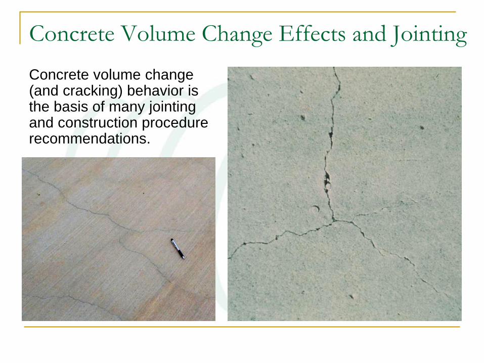
Concrete volume change (and cracking) behavior is the basis of many jointing and construction procedure recommendations.
Concrete Volume Change Effects and Jointing

Shrinkage + Restraint = Cracking
Cracking results from combined effects of restraint and shrinkage (drying and/or thermal)…
…whenever resulting tensile stresses exceed tensile strength.
Drying Shrinkage and Cracking

Why Are Joints Needed in Concrete Pavement?
Control the location, width, and
appearance of expected
cracks.
Accommodate normal slab
movements.
Reduce stress build up.
Provide load transfer where needed.
Minimize performance
implications of any random
(unexpected) cracks.

JOINT SPACING
How to determine…

Joint Design & Layout Affect Performance
Spacing Issue

The extent of cracking due to key
influences is somewhat predictable;
joints can be spaced accordingly.
Recommended Spacing
Exception: good design may call for even closer
joint spacing due to load transfer considerations.
Joint Spacing

Rules of Thumb for Jointing & Slab
Dimensions
Spacing:
Recommendation of 2.5 times the depth in feet
For example: 4” thick = 10’ maximum (4 x 2.5)
Panel shall be kept as square as possible
L:W of 1½:1 (Maximum length to width ratio)

Slab Length & Related Design Factors
Experience indicates that there is an increase in transverse
cracking when the ratio L/ℓ exceeds 4.44 (L=slab length).

Slab Length vs. Pavement Thickness Relationships
Using the criterion of a maximum L/ℓ ratio of 4.44, the allowable joint spacing would increase with increased
slab thickness but decrease with increased (stiffer) foundation support conditions.

TYPES OF JOINTS

Definitions - Joints
Contraction/Sawcut Construction
Longitudinal
Isolation

Types of Joints: Schematic Representation
Contraction or Control
Construction
Isolation

Expansion Joints Pavement expansion joints are only needed when:
1. the pavement is divided into long panels (60 ft or more)
without contraction joints in between to control transverse
cracking.
2. the pavement is constructed while ambient temperatures are
below 40°F (4°C).
3. the contraction joints are allowed to be infiltrated by large
incompressible materials.
4. the pavement is constructed of materials that in the past
have shown high expansion characteristics.
Under most normal concrete paving situations, these criteria do
not apply. Therefore, expansion joints should not normally be
used.

CONTRACTION (CONTROL) JOINTS Also called sawcut joints…

Joint Sawing/Forming

Tooled Control Joints
Advantages:
Simplest to make.
Most reliable crack initiation.
Disadvantages:
Most noticeable joint.
Not smoothest for rolling wheels.
Not designed for sealers / fillers.
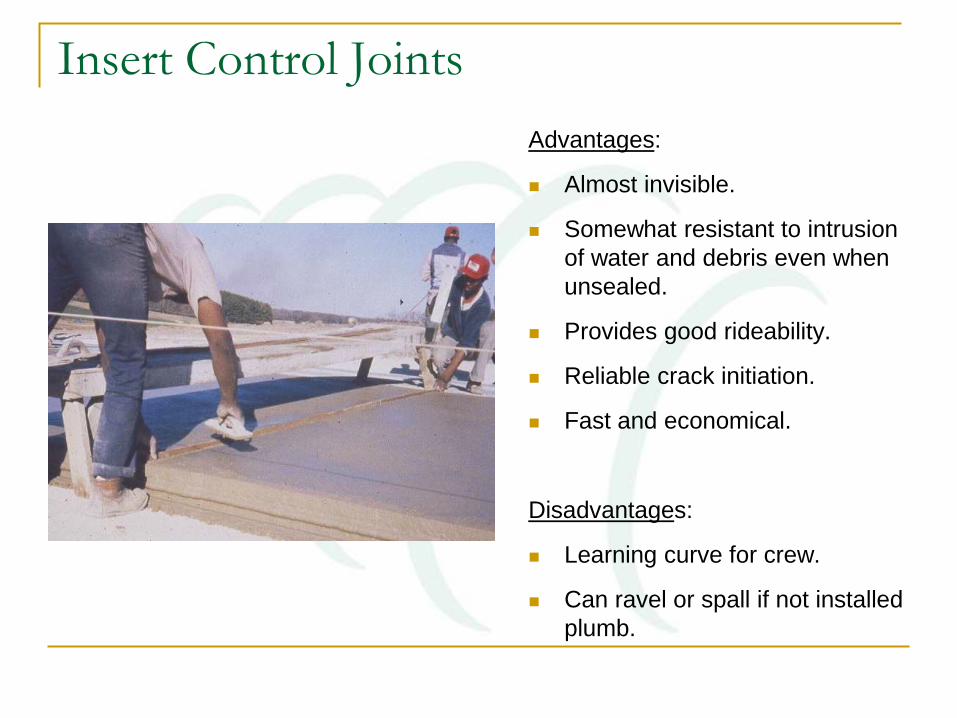
Insert Control Joints
Advantages:
Almost invisible.
Somewhat resistant to intrusion
of water and debris even when
unsealed.
Provides good rideability.
Reliable crack initiation.
Fast and economical.
Disadvantages:
Learning curve for crew.
Can ravel or spall if not installed
plumb.

Spalling Results If The Insert Is Not Plumb

Advantages:
• Makes best sealant reservoir.
• Not as noticeable as tooled.
• Smoothest for wheels.
Disadvantages:
• Timing is critical to success -
least reliable crack initiation
with gravel aggregates.
• Expensive to make.
Sawcut Control Joints

Rules of Thumb for Sawcut Joints
Depth:
Conventional Sawing:
Minimum of ¼ of the depth: e.g. 8” thick = 2” deep
Recommended
Early Entry Sawing:
Typical 1” to 1.5” depth
3
t

Sawcut joints with
conventional saws must be
made within 4-12 hours after
final finishing.
This joint was sawed at correct time
This one was sawed too late
Timing of Joint Sawing–A Critical Factor

Saw Blades
Most common are industrial diamond (require water cooling) or abrasive (carborundum).
Must match the saw blade to the concrete which is based primarily on aggregate hardness but also depends on power output of saw.
Very thin blades (~2 to 3 mm) may be used when joint sealing is not specified.

Early Entry “Dry Cut” Saws
Designed to initiate
cracks with a shallow
cut made much earlier
than with wet-cut
saws.
Timing - “window of
opportunity” is 1 to 2
hours.

No Speeding!
Sawing speed controls cut depth; hard aggregate might require a slower speed.
Speed typically controlled by saw’s self-propelling mechanism.
• Saw operators that attempt to speed up cutting may tend to push a
saw too fast, causing the blade to ride up out of its full cut… not
cutting to proper depth = risk for cracking!
Source: ACPA

CONSTRUCTION JOINTS

Construction joints are used between separate concrete
placements, typically along placement lane edges.
formed or slipped face
Butt joints are
recommended for
most parking lots
where load transfer
needs are minimal.
1st placement
2nd placement
Use of Construction Joints

Keyway Dimensions
D
0.1D
0.2D
1:4 Slope
0.2D
Trapezoidal Half-round
No longer recommended for light traffic pavements!

Keyway Construction Joints in
5” Thick Pavements

ISOLATION JOINTS

…are sometimes called expansion joints but should generally not be used to provide for expansion. They provide no load transfer and should not be used as regularly spaced joints in a joint layout. Their proper use is to isolate fixed objects, providing for slight differential settlement without damaging the pavement.
Isolation Joints

Improper Use of Isolation Joints
If isolation joints are used as routine joints:
Slabs “crawl” as isolation
joints compress.
Adjacent control joints
open and fill with debris.
No load transfer.
Failure of sealants.
Water intrusion.
Common issue in construction practice.

Common Details for Isolation of Fixtures Diagonal
Isolation joint
Inlet
Isolation joint
Circular
Isolation joint
Square with Fillets
Isolation joint
Inlet - Round
Isolation joint
Telescoping Manhole
No boxout or isolation joint necessary
None
Isolation joint around perimeter
Square
Isolation joint
Reinforcing bars recommended to hold cracks tight

Examples - Isolation of Fixtures

LONGITUDINAL JOINTS

Longitudinal Joints
Spacing Criteria:
Spacing of 12 to
15 feet serves as
both crack control
and lane
delineation.
Lanes (driveways)
that are greater
than 15’ require a
longitudinal joint.

Tie Bar Dimensions and Spacing (US)
Table 4.1—Tie bar dimensions and spacings (commonly Grade 60)*
Slab
thickness,
in. (mm)
Tie bar size ×length,
in. (mm)
Tie bar spacing, in. (mm)
Distance to nearest free edge or to nearest joint where movement can occur
10 ft (3.0 m) 12 ft (3.7 m) 14 ft (4.3 m) 24 ft (7.3 m)
5 (130) #4 x 24 (13M × 600) 30 (760) 30 (760) 30 (760) 28 (700)
6 (150) #4 x 24 (13M × 600) 30 (760) 30 (760) 30 (760) 23 (580)
7 (180) #4 x 24 (13M × 600) 30 (760) 30 (760) 30 (760) 20 (500)
8 (200) #4 x 24 (13M × 600) 30 (760) 30 (760) 30 (760) 17 (430)
9 (230) #5 x 30 (16M × 760) 36 (900) 36 (900) 36 (900) 24 (600)
10 (250) #5 x 30 (16M × 760) 36 (900) 36 (900) 36 (900) 22 (560)
11 (280) #5 x 30 (16M × 760) 36 (900) 36 (900) 34 (860) 20 (500)
12 (310) #5 x 30 (16M × 760) 36 (900) 36 (900) 31 (780) 18 (460)
*Corrosion protection should be used in an area where deicing salts are used on the pavement on a regular basis.

THE JOINTING PLAN

Jointing Plans and Details
Designer provides basic recommendations
regarding joint layout and other joint considerations
that affect pavement performance. May also provide
jointing plan.
Materials and construction specifications provide
requirements for acceptable joint placement
methods and the equipment that may be used.
Contractor implements the above requirements by
following or developing a comprehensive jointing
plan.
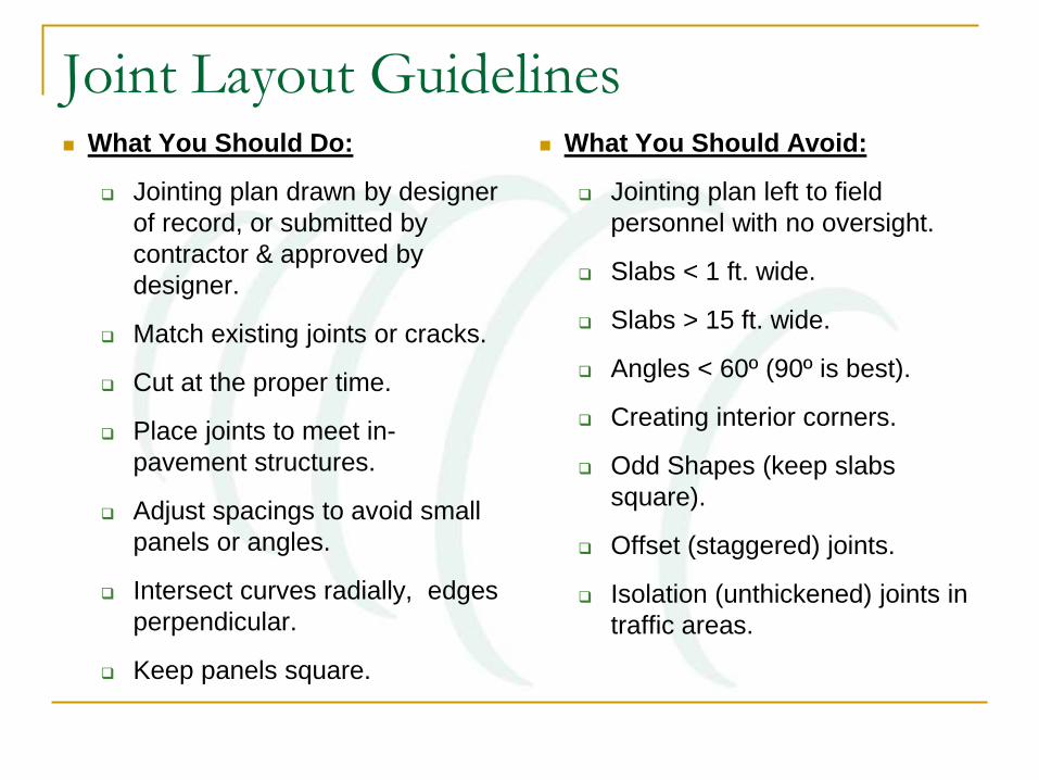
Joint Layout Guidelines What You Should Do:
Jointing plan drawn by designer
of record, or submitted by
contractor & approved by
designer.
Match existing joints or cracks.
Cut at the proper time.
Place joints to meet in-
pavement structures.
Adjust spacings to avoid small
panels or angles.
Intersect curves radially, edges
perpendicular.
Keep panels square.
What You Should Avoid:
Jointing plan left to field
personnel with no oversight.
Slabs < 1 ft. wide.
Slabs > 15 ft. wide.
Angles < 60º (90º is best).
Creating interior corners.
Odd Shapes (keep slabs
square).
Offset (staggered) joints.
Isolation (unthickened) joints in
traffic areas.

Jointing Layouts:
Corners, acute angles,
edges with extreme
curvature
Carry joint through curb
(integral curb shown)
Intersect joints
(Avoids acute angles)
Intersect at corners

Jointing Layouts:
Corners, acute angles,
edges with extreme
curvature
Meet structures at corners
Avoid acute angles
(Intersect at perpendicular)

Thickened Edges
Concrete at pavement edges or along isolation joints that will support wheel loads may be thickened to provide extra support.

Source: ACPA

JOINTING AND LOAD
TRANSFER

Load
Load
Without load transfer:
Excessive deflections and flexure - same as free edge loading.
With load transfer:
Deflections and flexural stresses are reduced.
Definition – Load Transfer
Shear strength provided at joints (or cracks) by dowels or
other features, aggregate interlock, or contact friction.
Significantly reduces load-related deflection.

Load Transfer Efficiency (LTE)

Load Transfer
Load Transfer is a Function of:
Aggregate Interlock
Stiffness of Supporting Layers
Mechanical Devices (i.e. Dowels)

Aggregate Interlock
Effectiveness depends on the crack width
and the spacing between joints.
Good for lighter traffic.
For ADTT greater than 100, aggregate
interlock may not be sufficient.

Factors That Enhance Aggregate Interlock Effectiveness:
Larger coarse aggregate sizes
Angular coarse aggregate texture (crushed vs. natural)
Thicker slabs
Shorter joint spacing
Stiff subbases
Edge support
Coarse-grained subgrade soils
Functioning drainage system
Aggregate interlock load transfer may not be sufficient for high
volumes of heavy truck traffic!

Stabilized Subgrades or Subbases in Relation to Joint
Considerations
Reduces:
Potential joint deflection,
Erosion potential.
Improves working surface, if necessary.
Use caution when using as permeable layers.
Extend 2’ beyond an unsupported slab edge.
Doweled Joints
Not needed on low volume streets and roads.
Especially when transverse joint spacing is less
than 15 feet.
May be justified when k values are less than
75 psi/in.
Generally, pavement must be at least 8” thick
to accommodate conventional dowels.

Dowels…
Generally not used in low volume situations. May be
needed when there is poor subgrade and/or many
trucks.
Dowels provide
load transfer
and allow the
joints to move.

Smooth Round Dowels

Dowel Bar Recommendations
Thickness
(in)
Diameter
(in)
Length
(in)
Spacing
(in)
< 10 1.25 18 12
10 or greater 1.50 18 12

Round Dowels in Baskets

Round Dowels in Baskets

Plate Dowels – Widely Used in Floor Slabs Now being used in some parking
areas / industrial pavements.
Accommodate some differential
movement longitudinally along the
joint.
Greater concrete bearing area, less
stress.
Can be effectively used in thinner
slabs than round dowels.
Efficient use of steel.
Diamond shapes for formed
construction joints.
Trapezoidal shapes in baskets for
control joints.

Diamond dowels for
construction joints:
Dowel receptacle is
nailed to form prior
to placement.
Dowel is inserted
into receptacle
after form removal.

Construction joints using
diamond dowel system

Plate/Diamond dowel system for both control joints and construction
joints – prior to concrete placement


JOINT SEALING
Do I or Don’t I…

Joint Sealing Topic of some debate.
Sealants must be maintained and drainage
design must be effective.
Low cost poured sealants not durable.
Some joint types difficult to seal.
Factors to consider in whether or not to seal
joints:
Traffic level
Soil types & local performance
Subbase use
Presence of wind blown debris

Joint Sealing
Minimize surface water & incompressibles into
pavement system in an attempt to reduce:
-Subgrade softening
-Pumping/Faulting
-Erosion of fines
-Spalling

To Seal or Not to Seal?
Sealing joints & maintaining well-sealed joints MAY
improve performance of the pavement; research into this
topic is ongoing…
… however, some agencies/owners no longer require
joints to be sealed under certain conditions
www.sealnoseal.org

Joint Sealants
Three basic types are:
Hot poured
Silicone
Preformed
Applicable specs for each type.
Specialty types (e.g., jet fuel resistant, self-leveling and no tooling, etc.), and backer rods are available in literature and from manufacturers.

Sealing? Make Certain the Joint is Clean!
All sealed joints must be
cleaned immediately behind
saw cutting or joint widening
and immediately prior to sealing
operations:
Removes saw-cut slurry, soil, sand,
etc.
Cleanliness of both joint faces is
extremely important to
concrete/sealant bond.

It’s Not Hard to Check…
If wiping a finger along the face picks up dirt or dust,
recleaning should be done before sealing!

Sealant Selection

Reservoir

Pavement Design Assistance Program
Image Source: South Dakota Ready Mix Assoc.
Concrete Parking Lots
Concrete Streets and Roads
•Conventional Concrete,
•Pervious Concrete,
•Roller-Compacted Concrete,
•Concrete Overlays, or
•Full Depth Reclamation.
•New Pavements, or
•Rehabilitation of Existing
Pavements

Pavement DAP – How do I obtain a DAP Report?
http://www.concretepromotion.org/index.html

Pavement DAP – Jointing Plan Assistance

Thank You!
Brian Killingsworth, P.E.
Senior Vice President, Local Paving
National Ready Mixed Concrete Association
Phone: (830) 438-2690
Mobile: (210) 508-4923
http://www.nrmca.org/about/Staff-Bio-BKillingsworth.asp
http://www.nrmca.org