concrete face rock-fill dam compared to roller compacted...
TRANSCRIPT

Concrete Face Rock-fill dam compared to
Roller Compacted Concrete dam A case study of dam constructions in Panama
Master of Science Thesis in the Master’s Programme Geo and Water Engineering
TOM KARLSSON AND JONAS TALLBERG
Department of Civil and Environmental Engineering
Division of Water Environment Technology
CHALMERS UNIVERSITY OF TECHNOLOGY
Göteborg, Sweden 2011
Master’s Thesis 2011:120
template
Replace the yellow marked text with your own title, name etc on the first nine pages.
Replace only the text and not the return-signs, comment marks [mp1] etc. Update all
field in the document by choosing Edit: Select All (Ctrl A) and then clicking the F9-
button. (The footers need to be marked separately and updated with the F9-button.)
Write your report using the formats and according to the instructions in this template.
When it is completed, update the table of contents.
The report is intended to be printed double-sided.


MASTER’S THESIS 2011:120
Concrete Face Rock-fill dam compared to
Roller Compacted Concrete dam A case study of dam constructions in Panama
Master of Science Thesis in the Master’s Programme Geo and Water Engineering
TOM KARLSSON AND JONAS TALLBERG
Department of Civil and Environmental Engineering
Division of Water Environment Technology
CHALMERS UNIVERSITY OF TECHNOLOGY
Göteborg, Sweden 2011

Concrete Face Rock-fill dam compared to
Roller Compacted Concrete dam A case study of dam constructions in Panama
Master of Science Thesis in the Master’s Programme Geo and Water Engineering
TOM KARLSSON AND JONAS TALLBERG
© JONAS TALLBERG AND TOM KARLSSON 2011
Examensarbete / Master of Civil Engineering
Chalmers tekniska högskola 2011:120
Department of Civil and Environmental Engineering
Division of Water Environment Technology
Chalmers University of Technology
SE-412 96 Göteborg
Sweden
Telephone: + 46 (0)31-772 1000
Cover:
An Autocad figure of a CFRD design for Changuinola II, described in Chapter 4.

Department of Civil and Environmental Engineering
Göteborg, Sweden 2011


I
Concrete Face Rock-fill dam compared to Roller Compacted Concrete dam
A case study of dam constructions in Panama
Master of Science Thesis in the Master’s Programme Geo and Water Engineering
TOM KARLSSON AND JONAS TALLBERDepartment of Civil and Environmental
Engineering
Division of Water and Environmental Technology
Chalmers University of Technology
ABSTRACT
This report compares two different dam types (Roller Compacted Concrete Dam and
Concrete Face Rock-fill Dam) in order to help the decision making when choosing
what dam type to build in Panama, where Vattenfall is involved in a joint venture to
build a dam called Changuinola II.
First a literature study was conducted to build a basic understanding regarding the two
different dam types. Material for this part of the report was mostly gathered through
conventional studying of books and reports, but also from conversations and lectures
with senior staff members at both Chalmers University of Technology and VPC
(Vattenfall Power Consultants).
The case study focuses on how other dam projects have progressed and what we can
learn from past experience. The dam projects studied are the construction of
Changuinola I, two dams in Rio Esti and the rejected project Changuinola-75. We
found that the studying of Changuinola I was of particular interest due to the fact that
that project faced the same issues this report is trying to answer.
Finally our findings are applied to the project of Changuinola II. We conclude that
Changuinola II should be constructed as an RCCD due to facilities, such as batching
plants and logistics centres, from Changuinola I still being present in the area.
Furthermore, a general proposal of which dam type that should be constructed cannot
be made due to the fact that external factors affect the choice hugely.
Key words: CFRD, Concrete face rock-fill dam, RCCD, Roller Compacted Concrete
dam, dam, construction, Changuinola

II
Jämförelse mellan två dammtyper, Concrete face rock-fill dam och Roller compacted
concrete dam
En fallstudie av dammbyggnader i Panama
Examensarbete inom Geo and Water engineering
TOM KARLSSON OCH JONAS TALLBERG
Institutionen för Bygg- och miljöteknik
Avdelningen för Vatten Miljö Teknik
Chalmers tekniska högskola
SAMMANFATTNING
Det här examensarbetet fokuserar på att jämföra två olika dammtyper för att
underlätta Vattenfalls beslutsprocess då företaget är involverat i ett
dammbyggnadsprojekt i Panama. De två dammtyper som jämförs är en såkallad
”Roller Compacted Concrete Dam” (i examensarbetet kallat RCCD) och en ”Concrete
Face Rockfill Dam” (i examensarbetet kallat CFRD).
Först utfördes en litteraturstudie för att bygga på den basala kunskapen om de olika
dammtyperna. Den största delen av litteraturstudien gjordes med böcker, men även
seminarier och samtal samt undervisning av kompetent personal på både Chalmers
och Vattenfall Power Consultants förekom.
Examensarbetet fortsätter sedan med en fallstudie av tidigare dammar som har byggts
i området där Vattenfall varit en del av projekteringen. De dammar som studerats är
Changuinola I, en damm vid floden Rio Esti samt ett förkastat projekt vid namn Chan-
75 som aldrig blev byggt. I fallstudien fann vi att Chan-75 var av störst intresse för
oss då projektet hanterade samma frågeställningar som examensarbetet försöker
besvara.
Slutligen appliceras resultaten av fall- och litteraturstudien på Changuinola II
projektet. Rekommendationen är att Changuinola II byggs som en RCCD av
anledningar som redovisas i rapporten.
Nyckelord: CFRD, Concrete face rock-fill dam, RCCD, Roller Compacted Concrete
dam, dam, construction, Changuinola

CHALMERS Civil and Environmental Engineering, Master’s Thesis 2011:120 III
Contents
ABSTRACT I
SAMMANFATTNING II
CONTENTS III
PREFACE V
1 INTRODUCTION 1
1.1 Background 1
1.2 Purpose 1
1.3 Problem 1
1.4 Method 2
1.5 Delimitation 2
2 DAM TYPES 3
2.1 Concrete Faced Rock-fill dam 3 2.1.1 History and expansion 4 2.1.2 Design 4
2.1.3 Material 12 2.1.4 Foundation 13
2.1.5 Construction 14
2.1.6 Risks and experiences 16
2.2 Roller-Compacted Concrete Dams 18 2.2.1 History and expansion 18
2.2.2 Design 18 2.2.3 Material 22 2.2.4 Foundation 24 2.2.5 Construction 24
2.2.6 Risks and experiences 26
3 CASE STUDIES 31
3.1 Rio Esti 32
3.1.1 Site description 33 3.1.2 Design 34 3.1.3 Construction 36
3.2 Changuinola I 36
3.2.1 Site description 38 3.2.2 Design 39 3.2.3 Construction 40 3.2.4 Challenges and experiences 40
3.3 Chan-75 41
3.3.1 Site description 41 3.3.2 Design 41

CHALMERS, Civil and Environmental Engineering, Master’s Thesis 2011:120 IV
4 CHANGUINOLA II 44
4.1 Site description 45 4.1.1 Site C 46
4.2 RCCD alternative 46
4.2.1 Design 47 4.2.2 Construction 49 4.2.3 Material 49
4.3 CFRD alternative 50 4.3.1 Dam design 50
4.3.2 Dam body 51 4.3.3 Sealing design 52 4.3.4 Spillway design 53
4.3.5 Diversion 53 4.3.6 Final design 55
5 CONCLUSION AND DISCUSSION 57
5.1 Conclusion 57
5.2 Discussion 57 5.2.1 Problems 57
5.2.2 Further work 58
6 REFERENCES 59

CHALMERS Civil and Environmental Engineering, Master’s Thesis 2011:120 V
Preface
We would like to thank everyone involved in the making of this report. Steffen
Häggström, our supervisor, who has provided us with invaluable input and writing
tips. We would also like to thank the staff at VPC (Vattenfall Power Consultants) who
were kind enough to let us take part of their work, as well as providing us with
extensive material and office space. A special mention also goes out to Anna
Gyllenswärd, who has helped us with picture editing and general layout design.
Lastly we send our gratitude to our examiner, Lars Bergdahl, for making this report
even possible. This would not have been done without him.

CHALMERS, Civil and Environmental Engineering, Master’s Thesis 2011:120 VI
Abbreviations
CFRD Concrete faced rock-fill dam
MD&A Malcom Dunstan & associates
RCCD Roller compacted concrete dam
RMR Rock mass rating
RQD Rock quality designation
VPC Vattenfall power consultant AB


CHALMERS, Civil and Environmental Engineering, Master’s Thesis 2011:120 1
1 Introduction
1.1 Background
In Sweden very few water power stations have been built during the last decades.
Thus there is very little experience of dams built with RCC and CFR technique.
Internationally, CFRDs and RCCDs are common and in many parts of the world there
is a large potential for new water power stations. The company Vattenfall is currently
involved in pre-studies, layout design and project management in several international
projects.
Three dams in Panama are some of the international projects that Vattenfall is
involved in. The dam types considered are RCCD (Roller Compacted Concrete dams)
and CFRD (Concrete Faced Rock-fill Dams).
1.2 Purpose
The main purposes of this project is to gather and provide information, knowledge
and experiences about RCCD and CFRD dam types, compare them to each other and
gain knowledge that can be used in planning of other projects in the future. The
increased understanding should include, but not be limited to, how the choice of dam
type is done in regard to different parameters such as geotechnical and geological
properties as well as accessible material and its difficulties during construction.
1.3 Problem
The main problem is to analyze which dam type that is preferable for the construction
of Changuinola II.
This report is mainly divided into three parts. Part one is a description of RCCD and
CFRD with respect to design and construction. Part two will try to answer the
following questions.
What is the main difference between RCCD and CFRD?
How do these dams differ in regard to
- Geological and geotechnical properties of the surrounding area?
- Maintenance issues?
- Seismic loads?
- Economy in regard of construction, materials etc.?
Part three represents the main conclusions and results based on part one and two. The
results are then applied to Changuiola II.

CHALMERS, Civil and Environmental Engineering, Master’s Thesis 2011: 2
1.4 Method
Part one is a description of the two dam types, CFRD and RCCD. Knowledge about
e.g. design, foundation and construction are gathered is presented.
Part two is based on reports from already finished projects, mainly the Barrigon Dam
and Changuinola I in Panama. These projects are used as case studies along with
information from other projects worldwide. The original plans for Changuinola I was
to construct a CFRD at the same location, in the text referred to Chan-75. Because of
far-reaching plans and the amount of background material available, we have chosen
to also give a short description of this alternative. Part two also consist of a study of
the area for the planned dam Changuinola II.
Finally part three is a study of Changuinola II where part one and two are used as
base. Part three will describe and compare the different alternatives possible for
Changuinola II with focus on the features stated below. The main focus for the
evaluation of Changuinola II is on the two points below.
Material costs for construction of dam body.
Time spent, e.g. total construction time, man-hours, need of vehicles etc.
In addition to the topics above, following points are also discussed and evaluated.
Time and costs used for trial tests, e.g. full scale trial test for RCCD.
Preparation for construction, e.g. excavation, foundation, diversion and
construction of batching and crush plants.
Comparison of spillway design, space needed, difficulties etc.
These features are chosen from experiences from earlier constructions and in
discussion with supervisor.
1.5 Delimitation
The delimitations are done in order to obtain the purpose stated above. First the report
will concentrate only on the dam design and not take interest in powerhouse or any
other surrounding constructions.
Because of the limitation regarding time it has not been possible to consider all costs
tied to the construction. The emphasis has therefore been to the most distinguish costs,
based on experiences from earlier projects. The powerhouse part of the water power
plants is not treated.
The limitation will be as follow:
Geological and geotechnical challenges
Maintenance experiences, problems and risks
Seismic loads
Economy, pros and cons of the two different dam types
Development of dam construction for the future

CHALMERS, Civil and Environmental Engineering, Master’s Thesis 2011:120 3
2 Dam Types
Chapter 2 in this thesis aims at finding an overall description of the two dam types,
Concrete Faced Rock-fill Dams (CFRD) and Roller-Compacted Concrete dams
(RCCD). The chapter is divided into two parts, one for each dam type, where each
part consists of chapters describing e.g. design, construction, material use and risks.
2.1 Concrete Faced Rock-fill dam
Concrete faced rock-fill dams, CFRD, is the term used to describe a certain type of
dam that have a dam body of rock-fills or gravel that is compacted in layers.
Moreover, there is an anti-seepage system using a concrete face slab. The concrete
slab works like an impervious layer while the rock-fill body consists of granular
material which has a high permeability and supports the concrete face slab by giving
the dam stability. Figure 2.1 shows an example of a CFRD, the Mohale dam in
Lesotho.
Figure 2.1 Downstream view of the Mohale dam in Lesotho
(Frysinger, 2011)

CHALMERS, Civil and Environmental Engineering, Master’s Thesis 2011: 4
One of the main characteristics with the CFRD is that the dam type enables usage of
local materials from the riverbed and the compulsory excavations in the rock-fill dam
body, as opposed to using expensive material from quarries which may have to be
transported a long way etc. However, there are some quality requirements on the
aggregates which have to be met in order to be able to use them in the dam body. The
quality is mainly determined by the local geology and highlights the importance of
good geological surroundings in order to exploit all advantages with the dam type.
When designing CFRDs there are certain properties that have to be assessed
thoroughly such as zoning of the dam body, filling materials, design of the dam body,
various analyses and seepage control to name a few. (Vncold, 2008)
2.1.1 History and expansion
CFRD have a long history and have been in a hidden, but integral, part in human life
for centuries. They are basically an evolved embankment dam. According to Yang
(1999) the first embankment dam was built around 2000 B.C in Mesopotamia close to
Baghdad.
Due to its long history there is a vast knowledge base regarding the building
technique, the dam type can be found almost everywhere in the world. Embankment
dams, such as the CFRD, are still being built. Current projects span all over the world,
from Kárahnjúkar dam in Iceland in the north to Mohale dam in Lesotho, South
Africa in the south.
2.1.2 Design
There are many ways to design a CFRD. Recently Vncold (Vietnamese national
committee of large dams) produced a paper containing some fundamental design
guidelines on behalf of ICOLD (International committee of large dams). In this
guideline there is detailed information of how the designing of the dam body should
be performed, the quality of materials used, foundation treatments as well as design
values for the face slab etc. The guideline summarizes experience from building
CFRDs and gives a valuable overview of the potential difficulties of building a dam
of this type. (Vncold, 2008)
We have decided to look in to these parameters and shortly describe them.
2.1.2.1 Dam body design
The dam body design includes several properties of the CFRD are:
Inclination of the dam slopes
Crest properties and parapet walls
Height of the dam
Settlements of the dam body
A typical cross section for a CFRD project is shown in figure 2.2.

CHALMERS, Civil and Environmental Engineering, Master’s Thesis 2011:120 5
Figure 2.2 CFRD cross section with upstream and downstream cofferdams.
(Novak, et al. 2001)
When designing the dam slopes, consideration to the gravel material has to be taken.
If the material is of good enough quality, the up and downstream slopes can be
designed at a slope of 1:1.3 – 1:1.4. However, if the material consists of poorer quality
rock-fill the slopes should not be steeper than 1:1.5 – 1:1.6. (Vnocold, 2008) On the
crest of the dam there should be a parapet wall. Furthermore, Vncold (2008) suggests
that the crest width should be within the limits of five to eight meters wide. However,
the crest width is subject to the regulations of the local authorities as well as the
operation of the dam, perhaps there is a need for a road or other operations on the
crest.
The height of the dam is decided on an economical- as well as on a practical base. The
constructor and consultant have to calculate the reservoir volume and the height of the
dam in order to produce enough electrical power to ensure good economy within the
project. This means that also the variations of the river flow have to be considered.
(Vncold, 2008)
It is also important to make an analysis of the dam design to ensure that stresses and
deformation is within the set limits. Several models should be made on different parts
of the dam body. These include, but are not limited to, the concrete face slab,
perimeter joint of the dam body and rock-fill creep etc. When doing the analyses it is
important to include dynamic loading to see how the dam responds to seismic loads.
(Vncold, 2008)
If the dam is a high CFRD, above 100 meters (Vncold, 2008) it is also necessary to
make a stability analysis of the ground. It is also needed if the dam is constructed on
weak bedrock or a gravel foundation, if the seismic activity in the area is high, if the
dam is constructed with soft rock-fill materials or if there exists difficult terrain
conditions at the site.

CHALMERS, Civil and Environmental Engineering, Master’s Thesis 2011: 6
2.1.2.2 Zoning of CFRD
Ensuring good material for the CFRD body is essential to keep it competitive, both
from a technical and an economical stand point. The principle is that only a small part
of the dam filling materials should be excavated from quarries to make it cost
effective. This is enabled by dividing the CFRD body into zones that have different
properties, as shown in figure 2.3.
Figure 2.3 Zoning of the CFRD body
(Zhang, Wang, & Shi, 2004)
The zones can have different relative volumes depending on how large the dam
should be, surrounding geology, bank slopes etc. Figure 2.3Error! Reference source
not found. (Zhang, Wang, & Shi, 2004) presents the different zones from the dam
“Tianshengqiao 1” in China, where the following properties of the fillings are shown
Table 2.1.
Table 2.1 Material properties of zones shown in Figure 1
(Zhang, Wang, & Shi, 2004)
Material No. Material description Maximum particle size
[mm]
II A Processed Limestone 8
III A Limestone 30
III B Limestone 80
III C Sandstone and Mudstone 80
III D Limestone 160

CHALMERS, Civil and Environmental Engineering, Master’s Thesis 2011:120 7
These values give us an idea of how the materials of the zonings in the CFRD body
can look like. The values can vary slightly depending on the rock types of the bedrock
and the aggregates available, since the values are determined by material properties.
2.1.2.3 Upstream sealing
The concrete face slab functions like an impermeable unit. However, there are both
vertical and horizontal joints to allow some deformation on the slab to prevent
cracking and thus leakage through the dam body. (Vncold, 2008)
When constructing the face slab thickness, Vncold (2008) suggest that it should be
calculated as:
(VnCold, 2008)
Where T is the thickness in meters and H is the height of the dam, also in meters. This
suggests that the slab design gets thicker at the base since the variable, H, starts at
zero at the top of the dam. The minimum thickness of the slab should therefore be 0.3
m to allow for steel reinforcements and impermeable features.
(Vncold, 2008)
Figure 2.4 Placement of face concrete at Shuibuya dam in China.
HT 0035.030.0 (2.1)
HT 0035.040.0 (2.2)

CHALMERS, Civil and Environmental Engineering, Master’s Thesis 2011: 8
(China Gezhouba Group Corporation, 2010)
In some cases, the minimum thickness of the slab can be increased to 40 cm for
certain high CFRDs in narrow valleys to account for the easy extruded failure zone of
central face slabs during these conditions. (Vncold, 2008)
2.1.2.4 Joint seals
Since the face slab is casted in a stage-by-stage construction and not a homogenous
slab, there are joints between the different slabs. These can be sealed and reinforced in
numerous ways. To prevent seepage through the joints in the face slab it is important
to seal them properly. The most important joint to seal, is however the perimeter joint
which is between the face slab and the concrete plinth. The plinth connects the slab
with the foundation. (Tan ev, 2005)
This is usually done by installing sheet plates. In some occasions asphalt is used in
between the sheet plates to seal the joints even better. However, the properties of the
asphalt need to be carefully chosen so that the asphalt does not become liquefied or to
stiff at extreme temperatures. (Reinus, 1968)
Some seals also include copper castings as well as PVC film. The most efficient way
to stop seepage through the perimeter joint is to use features of different materials and
shape at the same time. Tan ev (2005) proposes a design, which he states is the most
efficient one, shown in figure 2.5.
Figure 2.5 Perimeter joint
1. Concrete plinth
2. Waterstop of copper sheet
3. Rubber waterstop
4. Concrete bedding
5. Face slab
(Tan ev, 2005)

CHALMERS, Civil and Environmental Engineering, Master’s Thesis 2011:120 9
2.1.2.5 Design of concrete plinth
According to Sramoon (2010) the concrete plinth is the most important part of a
CFRD. The plinth is needed to connect the foundation with the face slab to form a
perimeter joint which functions as a primary water barrier. It is normally constructed
with reinforced concrete.
Figure 2.6 Loading conditions for the concrete plinth
(Sramoon, 2010)
The plinth is located on top of the bedrock underneath the dam. It should, according to
Vncold (2008), be joined with the bedrock trough grouted bolts, a so called grout
curtain. In figure 2.6 the loading condition for the concrete plinth is shown to give an
overview of how the loads are distributed upstream of the dam.
Table 2.2 Allowable hydraulic gradient of the rock foundation, if weathered
(Vncold, 2008)
Rock rot degree Allowable hydraulic gradient
Fresh weathering >20
Moderate weathering 10 – 20
Intense weathering 5 – 10
Full weathering 3 – 5

CHALMERS, Civil and Environmental Engineering, Master’s Thesis 2011: 10
The hydraulic gradient is sometimes called Darcy’s slope, which means it is the
difference between the head in two points divided with the distance along the flow.
The allowable hydraulic gradient shows the ability of the bedrock to withstand
leakage at an acceptable level, which is described in table 2.2. (Vncold, 2008)
2.1.2.6 Spillway and bottom outlet
There are several alternatives when designing the spillway and bottom outlet. For the
spillway there are two main types, spillway passing through the dam body and
spillway outside the dam body.
For embankment dam-types, such as the CFRD, the option of spillway outside the
dam body is most suitable. However, the spillway outside the dam body can also be
used in some concrete dams. Using crest spillways (spillways trough the dam body)
may increase the safety regarding flooding and overflow but that design is not
favorable for embankment dams. (Tan ev, 2005)
The spillway is also designed on behalf of the maximum flood occurrence which has
to be calculated so that the spillway can evacuate sufficient amounts of water. There
are three main spillway designs when considering the choice of a spillway outside the
dam body. These three options are:
Ogee spillway (figure 2.7)
Side-channel spillway (figure 2.8)
Shaft spillway (figure 2.9)
The Ogee spillway (figure 2.7), is a spillway structure that is placed near the dam
body. It consists of a constructed pathway with banks that leads the water past the
dam to the riverbed downstream. In the case of soil foundation, the ogee must be
prepared with facing and lining to counteract erosion etc. (Tan ev, 2005)
The side-channel spillway and channel (figure 2.8) is very similar to the frontal
spillway. However, the water intake is located to the side of the dam.

CHALMERS, Civil and Environmental Engineering, Master’s Thesis 2011:120 11
Figure 2.7 Ogee spillway
(Tan ev, 2005)
Figure 2.8 Side-channel spillway
(Tan ev, 2005)
CHALMERS, Civil and Environmental Engineering, Master’s Thesis 2011: 12
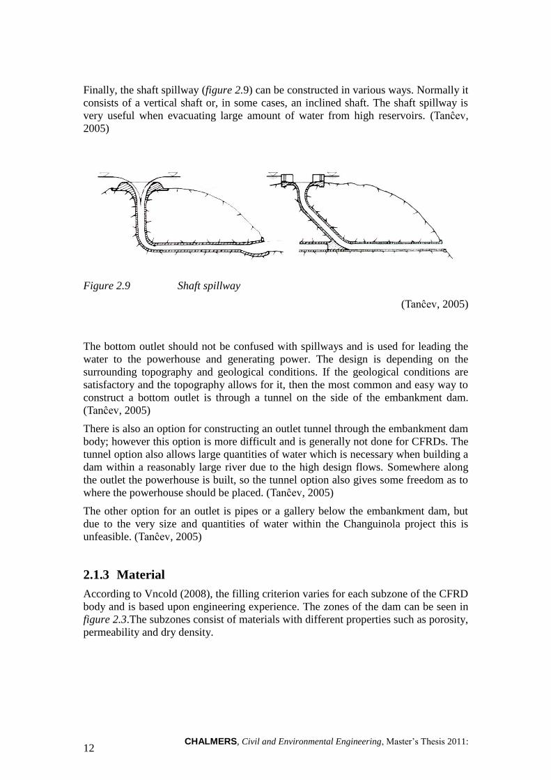
Finally, the shaft spillway (figure 2.9) can be constructed in various ways. Normally it
consists of a vertical shaft or, in some cases, an inclined shaft. The shaft spillway is
very useful when evacuating large amount of water from high reservoirs. (Tan ev,
2005)
Figure 2.9 Shaft spillway
(Tan ev, 2005)
The bottom outlet should not be confused with spillways and is used for leading the
water to the powerhouse and generating power. The design is depending on the
surrounding topography and geological conditions. If the geological conditions are
satisfactory and the topography allows for it, then the most common and easy way to
construct a bottom outlet is through a tunnel on the side of the embankment dam.
(Tan ev, 2005)
There is also an option for constructing an outlet tunnel through the embankment dam
body; however this option is more difficult and is generally not done for CFRDs. The
tunnel option also allows large quantities of water which is necessary when building a
dam within a reasonably large river due to the high design flows. Somewhere along
the outlet the powerhouse is built, so the tunnel option also gives some freedom as to
where the powerhouse should be placed. (Tan ev, 2005)
The other option for an outlet is pipes or a gallery below the embankment dam, but
due to the very size and quantities of water within the Changuinola project this is
unfeasible. (Tan ev, 2005)
2.1.3 Material
According to Vncold (2008), the filling criterion varies for each subzone of the CFRD
body and is based upon engineering experience. The zones of the dam can be seen in
figure 2.3.The subzones consist of materials with different properties such as porosity,
permeability and dry density.

CHALMERS, Civil and Environmental Engineering, Master’s Thesis 2011:120 13
Table 2.3 Filling criteria for dam materials
(Vncold, 2008)
Material / Zone Porosity [%] Relative density
Cushion material 15 – 18
Transition zone 18 – 20
Main rock-fill zone 19 – 21
Downstream rock-fill zone <22
Gravel material zone 0.80 – 0.85
Also, the dry density can be derived from the porosity show in Table 2.3 if the rock
density is known. It is important that the mean dry density standard deviation of the
materials and zones are not bigger than 100 kg/m3 to ensure that the stability of the
dam is sufficient; the materials need to be homogenous. (Vncold, 2008)
2.1.4 Foundation
The main purpose of constructing a good foundation for the dam is to lessen the
deformation caused by the weight of the dam as well as increasing the compressive
strength of the bedrock, prevent seepage under the dam and erosion that may follow
seepage. According to Tan ev (2005), the requirements of any dam foundation
concern deformability, stability and water impermeability.
To prevent the seepage a grout curtain is used. The curtain grout should be well into
the bedrock depending on hydro geological conditions and lower the pressure lines
under the dam which originates from seeping water. (Renius 1968)

CHALMERS, Civil and Environmental Engineering, Master’s Thesis 2011: 14
Figure 2.10 Grout curtain
(Reinius, 1968)
The curtain grout works as an impermeable shield and consist of cement, or other
compounds such as silica sol, which is pumped into the bedrock under large pressures
and thus sealing cracks and stabilizing the rock. (Renius, 1968)
Embankment dams, such as CFRDs, are normally built on rock. However,
foundations of gravel can also be feasible due to embankment dams transmitting
relatively low stresses to the foundation. If the dam is being constructed on gravel, the
curtain grout becomes even more important due to the fact that gravel is much more
permeable than bedrock, depending on the bedrocks RMR and RQD values. (Novak,
et al. 2001)
RMR and RQD are two methods of classifying the quality of a rock by comparing,
amongst other variables, discontinuities of the rock mass.
2.1.5 Construction
The construction process of a CFRD is fairly straight forward. However, an
equilibrium rise of both upstream and downstream zones is required. When building
the CFRD, the backfilling level should also be slightly higher due to different
settlement behavior compared to the materials used for the front filling. (Vncold,
2008)
The pre-settlement of the dam body also needs consideration. It is inevitable that
settlements will occur within the dam body and if the face slab is constructed too
early, the risk of cracking and failure of the slab is increased. Vncold (2008)

CHALMERS, Civil and Environmental Engineering, Master’s Thesis 2011:120 15
recommends the presetting period to be 5 to 7 months and the settlement should not
be higher than 5-6 millimeters per month depending on how large (heavy) the dam is.
The materials used for construction could be taken directly out of the riverbed or from
a nearby crushing plant. If conditions allow, the gathering of materials is preferably
done from the riverbed. (Vncold, 2008)
During construction a water diversion may be used by retaining water using a
temporary cross section or allowing a flood passing cross the dam during extreme
flows. If a temporary cross section is used, then the requirements of the temporary
cross section should be met regarding sliding stability, seepage and high water
conditions. (Vncold, 2008)
2.1.5.1 Diversion
During the construction on a dam site, it is vital to divert the river flow in order to
progress with the dam building. Especially during construction of CFRDs since the
gravel material can be easily flushed away or cause damage to an unfinished dam
body. Both Tan ev (2005) and Novak (et al. 2001) suggest some diversion options
which help to facilitate the erection of the dam, shown in figure 2.11. During normal
conditions, cofferdams are used to create a good working space for the erection but
also to shelter the construction site from potential flash floods etc.
Figure 2.11 Example of diversion solution during the constructing period
(Novak, et al. 2001)

CHALMERS, Civil and Environmental Engineering, Master’s Thesis 2011: 16
There are two different types of cofferdam designs that preferably can be used when
building in a riverbed and there is a stream of water that needs to be controlled, which
is the same method used for the CFRD alternative. (Tan ev, 2005 and Novak, et al.
2001)
2.1.6 Risks and experiences
Safety monitoring of CFRDs should be based upon local regulations in the actual
country that the CFRD is being built in. However, there are some properties that
should always be monitored for high CFRDs according to Vncold (2008). Systematic
measurements and observations should be made before, during and after construction.
The idea is that observations made during the early phase of construction should guide
the construction resulting in a more optimized design in the later phase.
Vncold (2008) has designed a list with properties that should always be monitored at
high CFRDs. In this report we have focused on the risks that we consider are the most
hazardous for dams of concrete faced rock-fill type:
Overtopping
Frost and ice
Seismic loads
In the following chapters we will try to explain what the risks mean and how to avoid
them.
2.1.6.1 Overtopping
The biggest risk for a CFRD is the case of overtopping. According to (Chinnarasri,
2001) overtopping has caused CFRDs to fail numerous times in the past. When water
starts overtopping the dam, an erosion process starts which will reduce the dams
general stability and could cause the dam to fail.
To counter this risk, an internal warning system could be installed to indicate too large
flows in the river or too high levels in the reservoir. If this warning system indicates
dangerously high levels of water (usually the CFRD is designed for the 10,000 year
flood), the outflow though the spillways can be increased and the risk of overtopping
is then reduced although a decrease in energy output is also likely. (Chinnarasri, 2001)
2.1.6.2 Frost and ice
When building dams in colder climates, the temperature change during the year can
have some unwanted effects. For CFRDs this affects the concrete face plate.
Temperature contractions and expansions can cause cracking leading to leakage and
erosion of the concrete. The main dam body of the CFRD is, however, fairly resistant
to frost problems due to the permeable nature of the rock-fill. (Reinius, 1968)

CHALMERS, Civil and Environmental Engineering, Master’s Thesis 2011:120 17
2.1.6.3 Seismic
There are some cases of CFRD´s being subjected to seismic forces and earthquakes.
This can be potentially disastrous for the dam. It can fail or be heavily damaged due to
the dynamic forces of the earthquake. (Reinus, 1968)
Figure 2.12 Damage along the vertical joints at Zipingpu dam in China due to
earthquake.
(Wieland & Houqun, 2009)
In China this has been observed and studied by the Chinese committee of large dams
(Zeping, 2009) by firsthand experience. In 2008 an earthquake stroked the CFRD in
Zipingpu, measuring 8 on the Richter scale. This is the strongest earthquake a CFRD
has ever been subjected to. Even as this was a very intense earthquake the dam did not
fail, although the damages on the dam were substantial and the reservoir was filled
with water.
The main crest of the dam settled almost 800 mm, with more settlements higher up in
the dam body than in the lower parts, which should be expected. The face slab
suffered heavy cracking as well as the parapet wall on the dam crest. The cracking of
the face slab resulted in somewhat higher leakage. Also the seepage under the dam
increased after the quake. (Zeping, 2009)
The downstream slope was also affected by the earthquake. However, the deformation
of the downstream slope was not critical due to the two-part design of the slope where
the lower part of the slope had a lower inclination than the higher part. (Zeping,
2009)
After all, the water stopping effect of the dam was not fundamentally compromised
which concludes that CFRDs are very resilient to dynamic loads such as earthquakes.
(Zeping, 2009)

CHALMERS, Civil and Environmental Engineering, Master’s Thesis 2011: 18
2.2 Roller-Compacted Concrete Dams
Roller-compacted concrete dams have many similarities with conventional gravity
concrete dams. The dam is built to a certain height and depth where it can resist the
expected forces from the water by its weight. But instead of using rock-fill or earth-
fill as a CFRD, RCCD consist of concrete which is spread in thin layers and
compacted by vibrator rollers. Figure 2.13 shows the downstream view of the Mujib
dam in Jordan.
Figure 2.13 Downstream view of the Mujib dam in Jordan.
(Lahmeyer International, 2011)
2.2.1 History and expansion
The method is originally from the 1 s Canada where the forest industry needed a
durable paving material that could carry heavy loads. ( ortland Cement Association,
1 ) According to Tan ev (2005), the method was applied to concrete dams already
in the 1970s. The first dams were constructed in the early 1980s and PCA (Portland
Cement Association) refers to the first RCCD built in the United States, the Willow
Creek dam in Oregon that was finished in 1982. By 2000 more than 200 large RCCDs
have been constructed and RCCD is quickly becoming one of the leading dam types
in the world. (Tan ev, 2005)
2.2.2 Design
There is no set way to design an RCCD since RCC simply stand for the construction
method and material. The most common design is however the theoretical triangular
cross-section which functions as a gravity dam. Figure 2.14 shows a typical cross-
section for a RCCD.

CHALMERS, Civil and Environmental Engineering, Master’s Thesis 2011:120 19
Figure 2.14 Typical cross-section for a RCCD
1. RCC-layers, approximately 300 mm
2. Sealed upstream face
3. Drainage gallery
(Tan ev, 2005)
The cross-section can as well consist of a shaped crest, sloped upstream face, drainage
gallery and toothed foundation. (Tan ev, 2005)
2.2.2.1 Dam body design
The dam body can be built after various designs where arch dams and buttress dams
are most common together with the gravity dam. The choice of design is normally
done after considering the general environment and topography as well as geological
conditions for the foundation. The dam body of Changuinola I is designed as an arch
dam.
Arch dams are a type of construction method that is built to transfer the water loading
from the dam itself, to the banks. Conventional gravity dams, on the other hand,
transfer the loading from the upstream face to the foundation.
There are two basic construction designs for arch dams, shown in figure 2.15, one
with constant external radius along the height of the dam and the other with constant
central angle. (Tan ev, 2005)

CHALMERS, Civil and Environmental Engineering, Master’s Thesis 2011: 20
Figure 2.15 Arch dam design for RCCD
(Tan ev, 2005)
2.2.2.2 Upstream sealing
It is important to provide the RCCD with sufficient resistance to water leakage
(seepage). To achieve low permeability in the dam body Tan ev (2005) suggests a
number of measures that can be used for an upstream face treatment, some of them
shown in figure 2.16.
Geo-membrane
Asphalt layer
Higher content of binder in the cement in the vicinity of the upstream face
Both the geo-membrane and the asphalt layer are applied behind prefabricated
concrete panels that are placed as the upstream face of the dam.
Design 1 Design 2

CHALMERS, Civil and Environmental Engineering, Master’s Thesis 2011:120 21
Figure 2.16 Different alternatives for upstream sealing of RCCD using
conventional concrete.
(Schrader, 2011)
The method of using a concrete with higher binder close to the upstream face will
decrease the permeability by creating a water tight barrier of concrete with higher
quality. However, according to some theories in RCCD building the most permeable
part of the dam is the joints between the RCC layers and if these joints can be sealed
properly then the upstream face treatment might be unnecessary. (Tan ev, 2005)
2.2.2.3 Spillway and bottom outlet
Commonly, crest spillways are used for concrete dams. This means that excessive
flood water will be evacuated through the dam, using an overflow section. The
overflow section might be placed in the middle of the dam, or more to the sides,
shown in figure 2.17. (Tan ev, 2005)

CHALMERS, Civil and Environmental Engineering, Master’s Thesis 2011: 22
Figure 2.17 Example of overflow section
(Tan ev, 2005)
Usually, the bottom outlets consist of steel pipes embedded in concrete. It is
recommended to have at least two pipes, which gives more control of the outflow and
reservoir levels. They are fairly straightforward to construct when dealing with
concrete dams. The main purpose is to regulate the flow or provide water to the
turbines in the power house. (Tan ev, 2005)
2.2.3 Material
There are several options when it comes to the choice of material used for the RCC.
Novak (et al. 2001) mentions that research, mainly done in Japan and America, has
resulted in two distinct approaches in RCCD construction which demands different
materials.
The two approaches will result in different dam profiles as shown in figure 2.18.

CHALMERS, Civil and Environmental Engineering, Master’s Thesis 2011:120 23
Figure 2.18
(Moffat p.133)
The main difference between the two is the upstream sealing and the possibility of
constructing an optimized profile.
Since the RCCD constructed with a dry concrete that is more permeable than the
option of a high-paste compacted concrete, it needs a high-quality concrete membrane
for water stopping upstream. When using the dry concrete, it also becomes easier to
develop an optimum profile during construction.
Table 2.4 Composites of the different concrete mixes
(Novak, Moffat, Nalluri, & Narayanan, 2001)
Characteristics Lean RCC (RDLC) High Paste RCC
Cement + PFA (kg/m3) 100-125 > 150
PFA / (Cement + PFA)
(%) 0-30 70-80
Water to PFA + Cement
ratio 1.0-1.1 0.5-06
90-day compressive
strength (MN/m2) 8-12 20-40
mass RDLC
fill in 0.3m
layers
concrete base layer gallery
slipformed
concrete
facing if
required
no-fines
concrete
transition
and drain
zone
grout
curtain uplift relief drains
1.0-1.5m thick concrete
diaphragm slipformed
horizontally
grout
curtain
uplift relief drains
base layer
gallery
RCC hearting
in 0.3m
layers
horizontally
slipformed
facings

CHALMERS, Civil and Environmental Engineering, Master’s Thesis 2011: 24
Unit Weight (kN/m3) 23 25
Layer thickness (m) 0.3 0.3
Contraction Joints Sawn Sawn or formed
One important parameter is that the high-paste concrete, while having a higher
compressive strength, is demanding a lot more PFA or cement which can be difficult
to attain in desolate places. Specifications of the composites of the different concrete
mixes mentioned by Novak (et al. 2001) are shown in table 2.4.
2.2.4 Foundation
Foundation of the RCCD is very similar to the foundation described for CFRD. The
main difference is that the RCCD is much heavier and thus demand better bedrock
allowing the stresses produced by the dam weight and the water pressure. If the
bedrock is heavily foliated, the foundation may suffer from shearing failure according
to Tan ev (2005). Before and during construction of RCCD, the geological conditions
at the site must be investigated much more thoroughly than for example during a
CFRD project.
The foundation treatment of the Changuinola I dam has been covered in Design
Criteria Memorandum. Several tests of rock masses and geotechnical conditions have
been performed.
Due to the weight of the dam and the bedrock´s general condition, an excavation
foundation treatment has been carried out. The decision was made due to rather poor
RMR-values and the joint conditions.
In addition to the excavation, a grout curtain should also be constructed so the
foundation meets the set value of seepage of 2-3 Lugeon. (Changuinola Civil Works
Joint Venture, 2009)
2.2.5 Construction
The big advantage with RCCDs is the rapid and simple construction. According to
CA the construction method gained their popularity “because it proved to be less
expensive than conventional methods of dam construction, including rock-fill and
earth-fill construction.” The main reason to the smaller expense is assigned the shorter
construction time (Portland Cement Association, 2011). Also in Hydraulic structures
(Novak, et al. 2001) the shortened construction time is mentioned as one of the
advantages.

CHALMERS, Civil and Environmental Engineering, Master’s Thesis 2011:120 25
Figure 2.19 Example of layer thickness for a RCCD.
(Schrader, 2011)
The conventional RCCD is constructed in 300 mm layers, as shown in figure 2.19.
Concrete is spread from abutment to abutment by conveyor belts and dumpers before
it is compacted with vibratory rollers. The technique has been evolved in the later
years and the ambition to optimize the design has generated improvements of
different details in the construction. Some stated below.
The construction of RCCDs as arch dams.
The use of an impermeable upstream barrier. GEVR (Grouted Enriched
Vibratable RCC).
It is also important to have a full-scale testing of the RCC to ensure the quality of the
construction and that the concrete is impermeable enough, but also that the
construction equipment is functional as well as the education of the workers on how
an RCCD project is performed. Another reason to have a full-scale test is that the test
will yield important data on:
Aggregate mix
Concrete mix
Fresh concrete behavior
Hardened concrete behavior
In-situ behavior, such as compaction of the concrete and foundation

CHALMERS, Civil and Environmental Engineering, Master’s Thesis 2011: 26
2.2.5.1 Diversion
The sensitivity of the cofferdam structure is not as high for an RCCD as for a CFRD.
This means that less time and money can be spent on building smaller provisory
cofferdams since RCCDs can be erected much faster than a CFRD. Thus the
cofferdams only have to be designed for seasonal high flows and not more than
annual high flows. Furthermore, the RCCD structure is not as sensitive to erosion as
the CFRD, so overtopping of the cofferdams is not necessarily catastrophic. (US
Army Corps of Engineers, 1995)
2.2.6 Risks and experiences
The risks of building dams with RCC technique are, nowadays, well documented. The
experiences of these types of dams have increased and so has the know-how. We have
chosen to look closer at some risks we feel could have a real impact on the average
RCCD project. The common denominator for these risks are that they are all well
documented and their behavior is well understood and described in the leading books
of hydraulic structures.
The risk factors are described below:
Internal uplift
Sliding stability
Internal stresses and loads
Seismic loads
Frost and ice
Other considerations when building RCCDs also have to be made, such as bedrock
and foundation stability. However, those aspects are already described earlier in the
report.
2.2.6.1 Internal uplift
The internal uplift is caused by seepage through the concrete in the dam body. This
pressure is due to water penetrating along the upstream face as well as water seeping
through the foundation. This uplift pressure has caused several dam failures. The
seepage through the dam causes not only uplift pressures, but also chemical erosion
problems like hydratisation etc. (Renius, 1968)
To solve the problem of internal uplift in the dam body a drainage system can be built
in the dam. Normally this is done by constructing a drainage gallery inside the dam
which reduces the pressure downstream in the dam body. A drainage gallery in the
foundation reduces the water pressure and stabilizes the dam (figure 2.20). This
measure can also be used to improve the water permeability of the dam. (Renius,
1968)

CHALMERS, Civil and Environmental Engineering, Master’s Thesis 2011:120 27
Figure 2.20 Drainage gallery in foundation
(Reinus, 1968)
2.2.6.2 Sliding stability
There are three ways the stability of a gravity dam could be jeopardized according to
Tan ev (2005). These three includes sliding across the foundation or cracks in the
foundation, overturning of the dam loosing contact with the foundation and failure of
the concrete in the dams body or failure of the rock mass in the foundation.
The only real risk of those three scenarios is, according to Tan ev (2005), the dam
sliding across the foundation. One remediation of the risk is usually to form the
foundation with several “teeth” to stabilize the joint created with the foundation (see
figure 2.21). This however, is only really effective if the rock mass under the
foundation is considered good enough.

CHALMERS, Civil and Environmental Engineering, Master’s Thesis 2011: 28
Figure 2.21 Teeth to prevent sliding
(Tan ev, 2005)
Another way to eliminate this risk is to lower the uplift pressure under the dam. This
can be done by having a grout curtain under the dam front which will decrease the
pressure; if the grout curtain also is complemented with a drainage gallery the uplift
pressure will be greatly reduced. (Häggström, 2011 and Tan ev, 2005)
2.2.6.3 Internal stress and loads
The internal loads within the dam can be minimized by designing the profile of the
RCCD, especially for large dams. It is important that the stress levels give no tension
under any loading condition (full reservoir, empty reservoir etc.)
However, since multi-stage profiles are somewhat more expensive to build single-
stage design is often used today. Single-stage means that the downstream slope is
uniform while the multi-stage design consists of multiple angles of the slope, shown
in figure 2.22. (Novak, et al. 2001)

CHALMERS, Civil and Environmental Engineering, Master’s Thesis 2011:120 29
Figure 2.22 Downstream with multiple angles and with uniform slope.
2.2.6.4 Seismic
Earthquakes and dynamic loads affect the RCCD type quite differently than the
CFRD type. Since concrete dams are considered as compact elastic structures it is
important that the dynamic loads does not give tension stresses that can induce
cracking in the dam body. However, this risk is reduced in the design phase where
such loadings are considered.
There is also the risk of structural resonance when the dam is being subjected to
dynamic loads. Structural resonance is more likely to occur in high (large) dams
rather in smaller dams. This is because the natural frequency of the dam is normally
estimated as:
(Novak, et al. 2001)
Where H is the height of the dam and T is the length of the dam base. This basically
means that dams 20 meters high have a natural frequency of 15-25 Hz, depending on
base thickness. Dams 50 meters high have a corresponding frequency of 6-9 Hz.
Normally, major seismic shocks are in the range of 1-10 Hz. (Tan ev, 2005)
Resonance in the entire structure is very unlikely but due to inertia forces created by
the dynamic loading, local high-stress areas in the dam can produce cracking. These
effects can be reduced by designing the cross-section of the dam in such ways that the
vulnerable areas are satisfactory. (Novak, et al. 2001)
H
Tf
n2
600 (2.4)
α
β
γ
δ

CHALMERS, Civil and Environmental Engineering, Master’s Thesis 2011: 30
2.2.6.5 Frost and ice
When it comes to RCCDs, the frost can have some effect on the uplift pressure. If
frost is being allowed on the bedrock downstream of the dam, or on the face of the
downstream side, the uplift pressure will become greater thus increasing the risk of
sliding. However, the risk of overturning the RCCD will remain at a constant low
level. (Reinius, 1968)

CHALMERS, Civil and Environmental Engineering, Master’s Thesis 2011:120 31
3 Case Studies
When planning a dam project there is an infinite amount of choices to make. The most
urgent choices may be where to place the dam and what kind of dam construction
should be used. In this report the two different dam constructions CFRD and RCCD
are compared and evaluated. This is done on the basis of four case studies:
The Rio Esti Hydropower Project (Rio Esti) in the Chiriquí province is the
oldest project of the case studies and was finished already in 2003. The entire
hydropower project consists of two dams where the Barrigon dam, evaluated
in this report, is constructed as a CFRD.
Changuinola I in the Bocas del Toro province is the first part of the
Changuinola hydropower project. The dam is under construction when this
report is written (2010). Changuinola I was first planned as a CFRD (see the
study of Chan-75 below.) but plans were changed in an early stage and the
dam is now built with RCC-technique instead.
Chan-75 is used as a case study though it was never built. The dam was
planned as a CFRD, slightly lower than Changuinola I but higher than Rio
Esti. Chan-75 was replaced with the Changuinola I project.
Changuinola II is the second part of the Changuinola hydropower project and
it is under investigation (2010). Changuinola II is planned to be built as a
RCCD. It is very likely that the investments in Changuiola I can be useful in
this project, making an RCCD design more favorable than a CFRD. Though,
the aim of this evaluation is to give an overall and objective description of the
two dam types and therefore those advantages are excluded in the first run.
The four cases appear in text in the same order as listed above. The description is
based on the same aspects as the dam type description in Chapter 2. The aim of the
project is not to do any economical study of which alternative is preferable. It is
impossible to ignore that money is the main driving force when the choices are made.
This comparison between the case studies is used for evaluation of the Changuinola II
project since the case study for this dam is slightly different due to the fact that
Changuinola II is yet to be built.
Panama City
Bocas del Toro Province
Chiriqui Province

CHALMERS, Civil and Environmental Engineering, Master’s Thesis 2011: 32
Figure 3.1 Overview of Panama
The two case studies have the same layout in order to simplify the comparison. Below
follows a short description of the properties described for each case.
Site
This part describes the conditions for the different sites, which includes for
example geology, topography, flows and climate.
Design
This part aims to give a summary of the chosen dam design, CFRD or RCCD
and how the spillway is designed.
Construction
This part will describe the construction procedure.
Challenges and Experiences
This part describes what challenges that have appeared during design and
construction. It will also describe what experiences can be helpful in the
future.
3.1 Rio Esti
The Rio Esti hydroelectric power project was completed during 2003. It is located 400
km west of Panama City in the province of Chiriquí. The plant partially regulates the
daily flow during dry season and it is projected to have a total installed capacity of
120 MW. Besides canals, tunnels and powerhouses Rio Esti consists of two dams,
Chiriquí Dam and Barrigon Dam. (Swedpower, 2001)

CHALMERS, Civil and Environmental Engineering, Master’s Thesis 2011:120 33
Figure 3.2 Overview of Rio Esti Hydroelectric power project
1. Chiriquí dam 2. The canal 3. Barrigon dam
The Chiriquí Dam is a 213 meters long concrete dam located in the Chiriquí River. It
is 35.5 meters high and has an ungated spillway with a discharge capacity of 3,390
m3/s. The Barrigon dam, which is the one of interest for this project, is a 60 meters
high CFRD which has a chute spillway with a discharge capacity of 1077 m3/s.
(Swedpower, 2001)
The main part of the inflow to the Barrigon reservoir is water conveyed from Chiriquí
through a canal. The canal is a 6.1 km long concrete channel with intake in the
Chiriquí reservoir and outlet in the Barrigon reservoir. The position of the cannel is
shown in figure 3.2 and figure 3.3. (Swedpower, 2001)
The Barrigon Dam is a storage reservoir and has a total volume of about 47 million
m3. The operation elevation is between +218.0 and +222.0 m.a.s.l and gives an active
volume of 10 million m3. (Swedpower, 2001)
3.1.1 Site description
The dam site is mainly formed of volcanic sedimentary rocks and some more recent
fluvial deposits. The deposits, which can be found on the right side of the valley, can
be up to 35 meters deep according to the performed geological survey. The survey
also concludes that the bedrock can be considered to be of good quality. (AES
Panama, 2001:1)
CHALMERS, Civil and Environmental Engineering, Master’s Thesis 2011: 34
3.1.2 Design
The design for Barrigon Dam is distinct described in ―Esti Hydroelectric Project:
Owner's technical requirements, part B - Design requirements and criteria‖ (AES
Panama, 2001:1) and this part will contain the most important features and
assumptions. First it is a description of the criteria determining what properties are
used for design. Followed by summary of the design details used for Barrigon Dam.
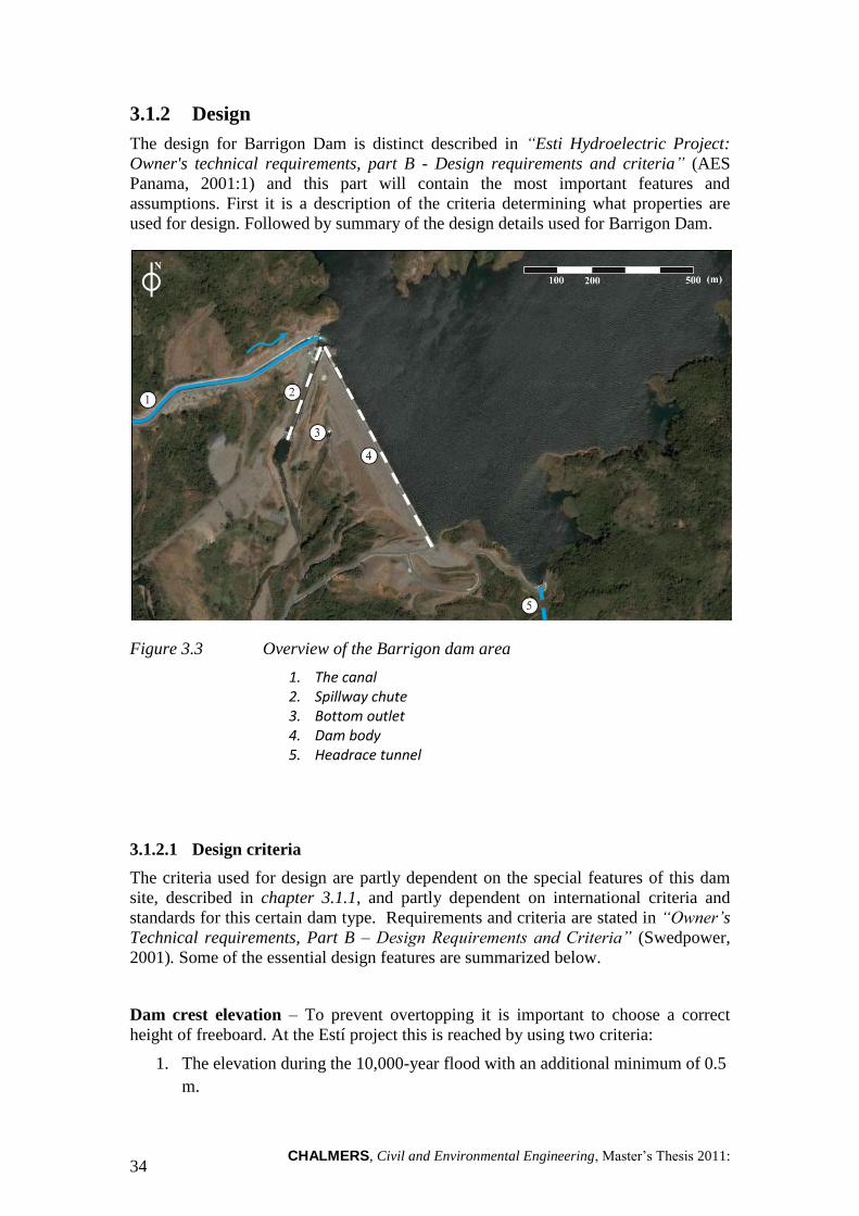
Figure 3.3 Overview of the Barrigon dam area
1. The canal 2. Spillway chute 3. Bottom outlet 4. Dam body 5. Headrace tunnel
3.1.2.1 Design criteria
The criteria used for design are partly dependent on the special features of this dam
site, described in chapter 3.1.1, and partly dependent on international criteria and
standards for this certain dam type. Requirements and criteria are stated in ―Owner’s
Technical requirements, Part B – Design Requirements and Criteria‖ (Swedpower,
2001). Some of the essential design features are summarized below.
Dam crest elevation – To prevent overtopping it is important to choose a correct
height of freeboard. At the Estí project this is reached by using two criteria:
1. The elevation during the 10,000-year flood with an additional minimum of 0.5
m.

CHALMERS, Civil and Environmental Engineering, Master’s Thesis 2011:120 35
2. Maximal normal operating elevation plus wave run-up and an additional
minimum of 0.5 m.
Seepage – The maximum seepage loss for Barrigon dam is 200 liters/ second.
Spillway – Spillways are designed with capacity to discharge the 10,000-year flood.
3.1.2.2 Dam body design
As mentioned above Barrigon Dam is built as a Concrete Faced Gravel Dam / Rock-
fill Dam with a crest length of 675 meters. Figure 3.4 shows a cross section of the
dam construction with numbers referring to the text below. (Swedpower, 2001)
1. The height of the dam is 60 meters with a freeboard of 2.75 meters.
2. Upstream slope is 1:1.5.
3. As face a 300 mm reinforced concrete face is used.
4. Downstream slope is set to 1:1.6.
5. The crest width is 6 meters
6. The dam body is split into several zones of different granular materials.
3.1.2.3 Spillway design
An important detail not shown in figure 3.4 is the spillway solution. The spillway is
designed with three radial gates to control the floods. All gates are 6 meters wide,
10.5 meters high and have a still level at +211.0 m.a.s.l. The gates starts to operate
when reservoir level reaches +222.0 meters, maximal operation level, and then
operate in stages until they are fully open when reservoir rises to +222.5 m.a.s.l. (AES
Panama, 2001:1)
Figure 3.4 Cross section of the Barrigon dam
During construction the river will be diverted through the bottom outlet culvert, later
used for emergency drawdown. The culvert is dimensioned to control the 1 in 50 year
flood flow (464 m3/s). (AES Panama, 2001:1)
60
6
192
Upsteam slope 1:1.5 Downstream slope
1:1.6
[m]
CHALMERS, Civil and Environmental Engineering, Master’s Thesis 2011: 36
3.1.3 Construction
The construction of the Barrigon CFRD is executed in several steps, diversion
culverts, excavation, concreting of plinth, reinforcement, fill of zones in different
stages, face construction, parapet wall and finally the filling procedure. (AES Panama,
2001:2)
Diversion of the river is mandatory preparative work in order to proceed with dam
excavation and concreting of the plinth. An excavation for the diversion culvert is
done along the proposed alignment. When a suitable rock foundation is confirmed, the
excavation is widened enough to accommodate the diversion culverts. When
excavation is done the culvert can be concreted. (AES Panama, 2001:2)
Before the river is diverted the excavation works are confined to the abutment areas.
When the diversion culverts are in use and the flood plain is dewatered, excavation
works can be extended to the whole foundation area. Concreting of the plinth at the
upstream toe is performed and when the concrete has gained sufficient strength,
grouting is started from the plinth surface. (AES Panama, 2001:2)
3.2 Changuinola I
Changuinola River lies in the far north-west of Panama in Bocas del Toro province. In
2003 the first water rights concession was issued to Hydroteribe S.A. Though, the
company had not enough financial resources and in 2004 the water rights were sold to
AES Changuinola S.A. AES is one of the largest power companies in the world and
has a capacity to serve 100 million people worldwide. In Panama AES is the largest
energy producer with a capacity of more than 480MW. (AES Changuinola, 2008)
The project head is between the elevation +320 and +55 m.a.s.l and the original plan
was to split the range into three power stations, according to figure 3.5. Problems with
the projects economical feasibility made it desirable to raise the reservoir level for
Chan-75 to +165 m.a.s.l, which inundated the power station for Chan-140.

CHALMERS, Civil and Environmental Engineering, Master’s Thesis 2011:120 37
Figure 3.5 Original plans for Changuinola Hydropower project
Figure 3.6 Final solution for Changuinola Hydropower project
The layout was now changed and the three projects were reduced to two large
projects, Changuinola I and II (figure 3.6). Changuinola I has the same position as the
former Chan-75 and Changuinola II is placed about two kilometers upstream the

CHALMERS, Civil and Environmental Engineering, Master’s Thesis 2011: 38
confluence of Changuinola and Culubre rivers. (Changuinola Civil Works Joint
Venture, 2009)
Figure 3.7 The Changuinola project area
The construction of Changuinola I started in October 2007 and the commercial
operation is estimated to start early 2011. To a large extent Changuinola I is the same
project as the original Chan-75. The main differences are stated below:
1. The reservoir elevation is raised from +152 to +165 m.a.s.l.
2. The dam type is changed from a CFRD to an RCCD.
According to AES Changuinola the project will have an annual average generation of
almost 1,050 GWh and the approximate investment will be 563 million dollars. (AES
Changuinola, 2008)
As mentioned above the first plan was to build a CFRD but after some reconsideration
it was decided to build a RCCD instead. According to Frostberg (2010) the decision
was made due to the following four arguments:
1. Economy
2. Construction time
3. Problems with space for spillway and diversion for CFRD
4. Expensive diversion tunnels under the dam for CFRD
3.2.1 Site description
The area at Changuinola River is characterized by very steep slopes and a deep river
valley. The geology and geotechnical properties of the area are, however, poorly
studied which means that the case study will lack certain valuable information
regarding said properties. (Monaghan, 2007)

CHALMERS, Civil and Environmental Engineering, Master’s Thesis 2011:120 39
3.2.2 Design
Figure 8 shows an overview of the Changuinola I dam construction.
Figure 3.8 Plan layout for Changuinola I during construction.
1. Left abutment
2. Right abutment
3. Dam body with uncontrolled ogee spillway
4. Downstream cofferdam
5. Upstream cofferdam
6. Diversion inlet and outlet
7. Diversion channel
(Changuinola Civil Works Joint Venture, 2009)
N
0 200 400 m

CHALMERS, Civil and Environmental Engineering, Master’s Thesis 2011: 40
3.2.3 Construction
3.2.3.1 Material
The total volume of concrete needed for Changuinola I is approximately 900,000 m3
(Changuinola Civil Works Joint Venture, 2009). Therefore, the access to cement, fly
ash and aggregate is essential during construction. The concrete is produced in a
batching and mixing plant located just downstream the construction site. From there
the concrete is delivered to the dam wall by a conveyor belt.
Besides the importance of efficient production and transportation of the RCC, the
access of raw material is essential to an effective construction. Following chapter will
describe the producing of RCCD at Changuinola I.
3.2.3.2 RCCD
The production of an RCCD can roughly be divided into four parts.
1. Raw material supply. Such us cement, aggregate, fly ash and water.
2. Batching and mixing
3. Transportation to construction site.
4. Construction, spreading and vibrating.
To achieve efficiency during the construction period it is essential to take all these
parts in consideration and make them work smoothly.
It is preferable to have a nearby access to raw material as it is of such a great
importance for the construction. It can be assumed that water supply won’t be any
problem at this site and will therefore not be treated here.
Cement and fly ash have to fulfill certain criteria and also have a steadiness in their
quality. This is necessary in order to warrant an even and high quality of the concrete
in an RCCD. At the Changuinola I project it was not possible to meet these demands
in Panama and therefore both cement and fly ash were shipped from Florida, United
States. (Frostberg, 2010)
According to Frostberg (2010) the choice of shipping material from Florida lead to
significant problems with logistics. The cement and the fly ash were shipped to the
harbor in Amirante. Those continuous transportations were made on a ship specially
modified for this purpose. Cement and fly ash were pumped into two silos and from
there loaded on trucks for transportation to the batching plant at Changuinola.
3.2.4 Challenges and experiences
The challenges for the Changuinola I project are similar to the standard dam
construction problematics; materials and location.
The construction of a RCCD at Changuinola I have not been totally fuss-free.
According to Gunnar Frostberg problems have occur as an affect of underestimations
of the complexity of the problems and too optimistic approach concerning the time
aspect. Frostberg (2010) is pointing at:
CHALMERS, Civil and Environmental Engineering, Master’s Thesis 2011:120 41
Access to cement and fly ash of sufficient quality. In the case for Changuinola
I this has been bought from Florida, US, leading to extended logistic problems
compared to a local solution in Panama.
Numerous tests are required in order to get a proper aggregate mix. Plants for
aggregate crushing has to be built if they don not already exist.
Numerous tests have been done in order to find a proper formula for the RCC.
It has also been an extensive work finding rock that satisfies the necessary
criteria.
It is not possible to cast RCC when it rains more than 0.2 – 0.5 mm per hour,
which can occur in this region.
Capacity for batching plant and conveyor belts also limits the construction
speed.
According to Frostberg (2010) it takes about 12 months to cast RCC for a dam with
similar size as Changuinola I. But it is important to be well prepared for those
parameters mentioned above.
3.3 Chan-75
The Changuinola Hydropower Project has been re-projected several times and there
have been a lot of different design alternatives. Because of the access to material
about earlier plans and the near relation to Changuinola II, it will follow a summary of
the plans for Changuinola I as a CFRD. These plans are most often referred to as
Chan-75.
Chan-75 is the original plans for the Changuinola River. The dam was designed as a
CFRD and the preliminary design was evaluated in 2005 and it is located at the same
place as Changuinola I. This chapter is based on the background material from these
plans and it is noteworthy that this dam has not been built. For further information
about the project see chapter 3.2.
3.3.1 Site description
Site description is the same as for Changuinola I, chapter 3.2.1.
3.3.2 Design
As mentioned above Chan-75 is a stage in developing the Changuinola Hydropower
Project. This chapter describes the first stages of the plans for building a CFRD. This
is not a constructed project. The plans are therefore less detailed than for the other
projects. However the plans are of interest because of the similarities with
Changuinola II. Figure 3.9 shows the final design proposal.

CHALMERS, Civil and Environmental Engineering, Master’s Thesis 2011: 42
Figure 3.9 Plan layout for Chan-75 during construction.
1. CFRD body
2. Spillway gates
3. Spillway Chute
4. Cofferdams, for construction only
5. Diversion inlet/outlet, for construction only
6. Power house
(Gavilan group, 2005)
N

CHALMERS, Civil and Environmental Engineering, Master’s Thesis 2011:120 43
3.3.2.1 Dam body design
Figure 3.10 shows the dam body in profile.
Figure 3.10 Profile view of Chan-75
(Gavilan group, 2005)
3.3.2.2 Spillway design
The spillway for Chan-75 was preliminary designed as shown in figure 3.11. It
consists of four gated spillways, each 16 meters wide and 18.5 meters high. This
design would give a possible discharge capacity of 10,000 m3/s.
Figure 3.11 Spillway design for Chan-75
(Gavilan group, 2005)

CHALMERS, Civil and Environmental Engineering, Master’s Thesis 2011: 44
4 Changuinola II
Changuinola II will be located a few km upstream the site for Changuinola I in the
Changuinola River. Further location details are described in chapter 3.2 and in figure
4.1. The head elevation for Changuinola I is +165 m.a.s.l and it is reached somewhere
around two kilometers upstream the confluence of Changuinola and Culubre rivers.
In November 2007 a preliminary conceptual design was developed for how the
remaining head between +320 and +165 m.a.s.l shall be used. ―The preliminary
conceptual design‖ (Frostberg, 2007) is developed by VPC with assistance of
MD&A. This report is used as a base in this part, which will describe the alternatives
developed and evaluated by VPC and MD&A. There will also be a description of a
possible location and construction of a CFRD.
The ―The preliminary conceptual design‖ (Frostberg, 2007) considers three different
dam sites, A, B and C, and for all sites a RCCD is suggested.
In the report from 2007 (Frostberg, 2007) the biggest focus is on site C which
according to VPC would be the optimal site for a RCCD. A further development of
this assumption is done below in chapter 4.1.1.
As mentioned above this chapter will both describe a RCCD and CFRD alternative for
the constructing of Changuinola II. The RCCD alternative, developed by VPC and
MD&A, is described in chapter 4.2. The CFRD alternative, developed based on
descriptions in this report, is developed in chapter 4.3.
Figure 4.1 Overview of Changuinola River and the two dam sites,
Changuinola I and Changuinola II.
(Frostberg, 2007)
The preliminary conceptual design does only consider the alternative to constructing a
RCCD but according to Gunnar Frostberg (2010) it would be possible to build a
CFRD at for example site B. In order to compare the CFRD with RCCD it is
necessary to create a CFRD option. This chapter both gives a summary of the RCCD
alternatives in the Preliminary Conceptual Design and compares those with possible
CFRD alternatives.

CHALMERS, Civil and Environmental Engineering, Master’s Thesis 2011:120 45
4.1 Site description
Beneath three different site alternatives are described, A, B and C. The alternatives
are developed by VPC in assistance with MD&A and they are described in ―The
preliminary conceptual design‖ (Frostberg, 2007) and the following text is based on
this report. All three sites are located upstream of the confluence between
Changuinola and Culubre rivers, within a span of 1 km, and figure 4.1 shows the sites
intermutual location.
Figure 4.2 Locations for dam sites A, B and C
(Changuinola Civil Works Joint Venture, 2007)
As mentioned above the emphasis for the conceptual design (Frostberg, 2007) is in
site C, which is considered to be the most favorable site for a RCCD. In the report this
choice is based on the amount of concrete needed for the construction, shown in table
4.1. Assumptions and calculations for this decision are done on basis of satellite maps.
The obvious focus on site C in the ―The preliminary conceptual design‖ (Frostberg,
2007) will also reflect on this chapter.

CHALMERS, Civil and Environmental Engineering, Master’s Thesis 2011: 46
Table 2.4 Concrete amount for the dam sites
(Frostberg, 2007)
Dam site RCC
[Mm3]
GEVR
[m3]
Convetional
concrete, [m3]
Site A 1.46 67,760 22,810
Site B 1.84 79,220 22,810
Site C 1.15 47,620 22,810
The considerable smaller amount of concrete needed and the narrow floodway for site
C makes it more favorable for an RCCD. But according to Gunnar Frostberg (2007) it
would be possible to build a CFRD at site A which is not as narrow and have not as
steep embankments as site C. Therefore there is more room for diversion tunnels and
spillway.
Site A, the most upstream site, located about 2 km upstream of the confluence
with Culubre River. (figure 4.2)
Site B, located around 1600 meters from the confluence between Changuinola
River and Culubre River. As shown on the map (figure 4.2) the site is located
just upstream of a bend on the river.
Site C, the most downstream site located about 1 km upstream of the
confluence with Culubre River. As mentioned above this is the most favorable
site for constructing an RCCD.
4.1.1 Site C
According to Frostberg (2007), the valley slopes on both sides are very steep,
typically 65 degrees over 200 meters, which indicates very good rock mass quality.
RMR was estimated to around 73 while RQD was thought to be 24. Site C is also
thought to be particularly in favor for an arch dam type.
At the time for this report, no thorough geotechnical survey has been done which
leaves an uncertainty regarding some of the dam features such as the spillway
construction etc. This will have to be resolved before initiating the final design stage.
4.2 RCCD alternative
The plans in ―The preliminary conceptual design‖ (Frostberg, 2007) are to construct
an RCCD at site C. This construction will be described in the following text

CHALMERS, Civil and Environmental Engineering, Master’s Thesis 2011:120 47
4.2.1 Design
The dam body design is proposed as an arch dam due to the site conditions with steep
slopes and relatively narrow valley.
Figure 4.3 Preliminary dam body design for Changuinola II. Downstream face
to the left and upstream face to the right.
(Changuinola Civil Works Joint Venture, 2007)
4.2.1.1 Dam body
As previously stated, the report also suggests that a volume of about 1.1 million cubic
meters of RCC is needed to build the dam at site C. The concrete will be distributed in
the preliminary design as in figure 4.4.
Figure 4.4 Volume of the 300 mm thick RCC layers derived from the
preliminary design of the arch dam at Changuinola 2, Site C, for a
total volume of 1.1 Mm3.
Downstream face Upstream face
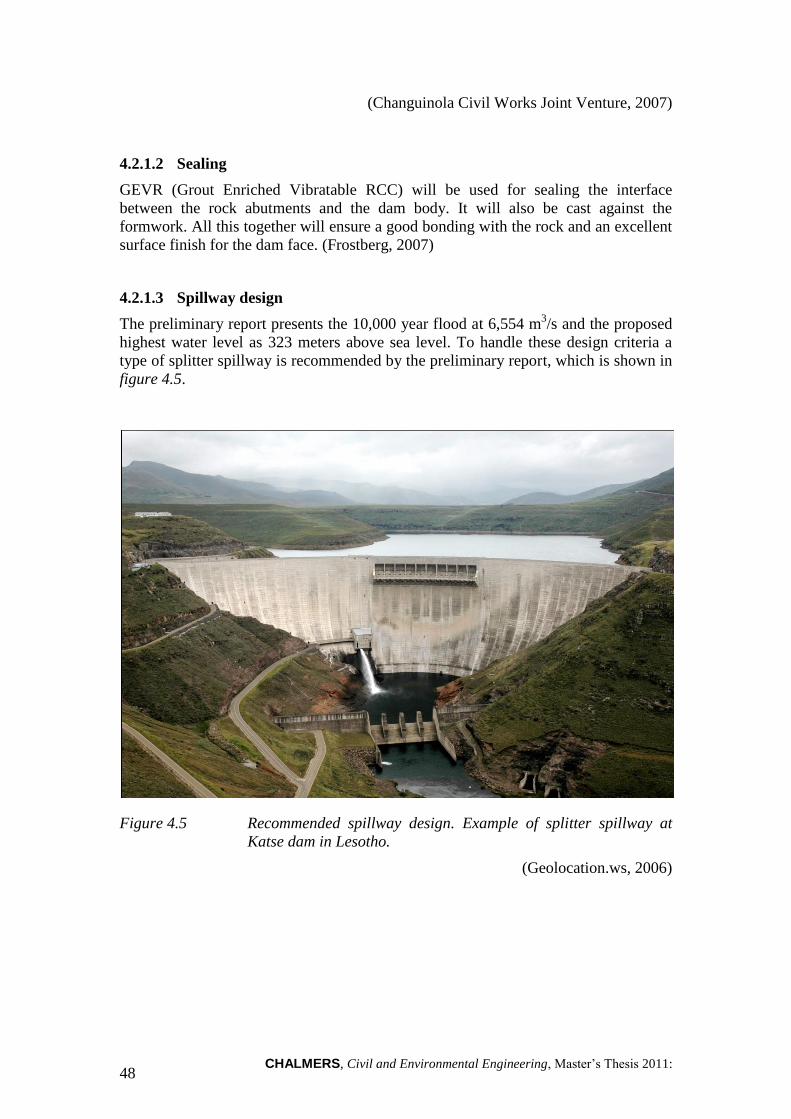
CHALMERS, Civil and Environmental Engineering, Master’s Thesis 2011: 48
(Changuinola Civil Works Joint Venture, 2007)
4.2.1.2 Sealing
GEVR (Grout Enriched Vibratable RCC) will be used for sealing the interface
between the rock abutments and the dam body. It will also be cast against the
formwork. All this together will ensure a good bonding with the rock and an excellent
surface finish for the dam face. (Frostberg, 2007)
4.2.1.3 Spillway design
The preliminary report presents the 10,000 year flood at 6,554 m3/s and the proposed
highest water level as 323 meters above sea level. To handle these design criteria a
type of splitter spillway is recommended by the preliminary report, which is shown in
figure 4.5.
Figure 4.5 Recommended spillway design. Example of splitter spillway at
Katse dam in Lesotho.
(Geolocation.ws, 2006)
CHALMERS, Civil and Environmental Engineering, Master’s Thesis 2011:120 49
4.2.2 Construction
4.2.2.1 Diversion
As diversion solution the preliminary conceptual design describes two solutions.
Diversion culverts along left or right abutment. (Preferred option)
Diversion tunnels in the left abutment. (Second option)
For the RCCD alternative the preferred option is used and therefore the only option
described in this chapter. The second option is assumed to be used for a CFRD and
therefore described in chapter 4.2.1.
The preferred option entails two reinforced concrete culverts, 9 times 9 meters, and
two cofferdams, one 20 meters high upstream and one 6 meters high downstream.
This corresponds to at least a four year recurrence interval flood and has clear
similarities with the diversion solution for Changuinola I. It is also noted in the
Preliminary conceptual design that it would be possible to enhance the diversion
capacity with higher cofferdams. (Frostberg, 2007)
4.2.3 Material
It is important to secure the availability of material of adequate standard. This is for
all components in the concrete mixtures, e.g. aggregate, cement, water and fly ash.
As aggregate supply the Frostberg (2007) suggest two solutions. The first alternative
is to extract the aggregate needed from alluvial deposits in the Changuinola River,
between the Changuinola I and Changuinola II. The second alternative is to
investigate a limestone quarry on the right abutment above the area.
Regarding cement and fly ash it is not possible to find a solution in ―The preliminary
conceptual design‖ (Frostberg, 2007). However, according to Gunnar Frostberg
(2010) the solution for Changuinola I was used because of the absence of adequate
material in the local area. Therefore it seems likely to assume that the same solution
will be used for Changuinola II, which imply transportation by ship from Florida to
Almirante harbor and further on by trucks to plants at dam site.
―The preliminary conceptual design‖ (Frostberg, 2007) also have conducted a pre-
study of how the entire dam site, with all installations, concrete and aggregate
production areas, as well as access roads might look like. Consideration has been
taken to where deposits of aggregates actually exist where the location of access roads
and concrete production areas is more of a logistical problem. Figure 4.6 show an
overview of the project area.
N

CHALMERS, Civil and Environmental Engineering, Master’s Thesis 2011: 50
Figure 4.6 1. Dam site
2. Concrete production area (option 1)
3. Concrete production area (option 2)
4. Aggregates production area
5. Alluvium deposit
6-10. Access roads
(Changuinola Civil Works Joint Venture, 2007)
4.3 CFRD alternative
Because the preliminary design only consists of RCCD alternatives it is necessary to
construct a CFRD alternative in order to make the comparison possible. In this part
previous chapters are used as base for the development of a CFRD alternative for
Changuinola II.
4.3.1 Dam design
It is likely to assume that the dam design will have a lot of similarities with the design
for Rio Esti and the planned CFRD alternative for Changuinola I (Chan-75), see the
CFRD section in figure XX. Therefore these two projects can be used as model for the
design in of a CFRD alternative for Changuinola II. It is important that the design fits
the certain properties at the Changuinola II dam site.
.
N

CHALMERS, Civil and Environmental Engineering, Master’s Thesis 2011:120 51
Figure 4.7 Section for Chan-75
(Gavilan group, 2005)
The most important difference when designing a CFRD for Changuinola II is the
height. The RCCD planned are distinctly higher than the CFRDs described in
previous chapter and this will obviously influence the design. Improvements are done
in accordance to chapter 1.
4.3.2 Dam body
The geometry of the dam body can be split into five parts, whereof four are shown in
section (figure 4.7).
1. Height
2. Upstream slope
3. Downstream slope
4. Crest width
And the fifth geometrical property is the crest length. If these properties can be
determined it will be possible to calculate the amount of rock-fill needed. Below
follows a description of how the determination is done.
The height is depending on head elevation chosen for the project. For Changuinola II
the head elevation is investigated in ―The preliminary conceptual design‖ (Frostberg,
2007) and set to +320 m.a.s.l. In combination with head elevation for Changuinola I,
+165 m.a.s.l, a dam height of at least 155 meters are needed.
Upstream and downstream slopes are chosen in accordance to chapter 2. Natural
gravel fill results in less steep slopes instead of what could be applied if rock-fill were
used. However, the access of alluvial material is hopefully very good and therefore it
will not be a problem.

CHALMERS, Civil and Environmental Engineering, Master’s Thesis 2011: 52
According to chapter 2 the crest should has width between 6 and 8 meters. Due to size
of the dam an 8 meter wide crest is used.
4.3.3 Sealing design
As described in chapter 2.1.2 and also in the case studies, sealing is done by using a
concrete face slab. Sealing to the foundation is done in combination with a concrete
plinth. In chapter 2.1.2, thickness of the concrete slab is calculated as:
(Vncold, 2008)
Where Tmin is 0.3 meters in the regular case and increased to 0.4 meters for high dams.
Hi is the distance from the top and Ti is the thickness at certain height. As described in
chapter 2.1.2 the increased thickness is used to avoid ruptures in the upper part of the
slab, due to compaction in the dam body. Using the given dam height of 155 meters a
horizontal joint should be placed approximately 50 meters from top for the central
slabs. Equation 4.2 gives the thickness at the top of the lower stage slab.
(Vncold, 2008)
Next step is to correlate the thickness at the top of the lower stage with bottom of the
upper stage.
(Vncold, 2008)
(Vncold, 2008)
Gives the following thickness for the upper stage (Hi<50m):
ii HXTT min (4.1)
475.0500035.030.050 T (4.2)
5040.050 XT (4.3)
0015.0
50
40.050
T
X (4.4)
ii HT 0015.040.0 (4.5)

CHALMERS, Civil and Environmental Engineering, Master’s Thesis 2011:120 53
(Vncold, 2008)
And for the lower stage:
(Vncold, 2008)
The increased thickness are only used for the central slabs were the stresses are
highest. For lower slabs closer to the abutments, equation 4.1 is used for the whole
height.
4.3.4 Spillway design
What spillway design to use depends on the design flood. The RCCD alternative for
Changuinola II are dimensioned to control the 10,000 year flood, which corresponds
to 6,554 m3/s. Comparing to Rio Esti and Chan-75, it is likely to assume that the
10,000-year flood is enough also for the design of a CFRD alternative.
Spillway for Chan-75 was preliminary designed for a capacity of 10,000 m3/s, which
will clearly be enough. Figure 3.11 shows the spillway design for Chan-75. As shown
it is four gated spillways, each 16 meters wide and 18.5 meters high.
4.3.5 Diversion
For diversion design it is assumed that the second option in chapter 3.7.2.1, diversion
tunnels in the left abutment, can be used. This alternative is originally designed for the
RCCD alternative and described in the ―The preliminary conceptual design‖
(Frostberg, 2007). However, it is in this report assumed that it is a suitable solution for
diversion design when constructing a CFRD. Assumptions are done in comparison
with diversion design for Rio Esti and Chan-75.
The diversion for the CFRD is designed with two circular tunnels in the left abutment,
each with a diameter of 9.9 meters. The lengths of the tunnels are 413 and 366 meters.
ii HT 0035.030.0 (4.6)

CHALMERS, Civil and Environmental Engineering, Master’s Thesis 2011: 54
Table 4.2 Lining options
(Frostberg, 2007)
Type of lining Lining
thickness [mm] Cross-sectional
area [m2]
Velocity1
[m/s] Velocity
2
[m/s]
Shotcrete 150 72.4 12.4 16.2
Concrete 500 62.2 14.5 18.9
1) 4-year design flood (1728 m
3/s)
2) 10-year design flood (2350 m
3/s)
There are two alternatives of lining for the tunnels (table 4.2), 150 mm shotcrete or
500 mm concrete. Diversion should be designed for a four year recurrence interval
flood (1798 m3/s), which corresponds to a velocity of about 12 m/s for the shotcrete
lining and about 14.5 m/s for the concrete lining. The shotcrete velocity is on the limit
for the shotcrete lining and at the same time the concrete velocity is well below limit.
This makes it likely to assume that concrete lining should be used. As bonus the
diversion solution would even manage the ten year recurrence interval flood of 2350
m3/s, which corresponds to a velocity of about 18.9 m/s.

CHALMERS, Civil and Environmental Engineering, Master’s Thesis 2011:120 55
4.3.6 Final design
This part is a brief description of what a CFRD alternative could look like for
Changuinola II. The figures made in AutoCAD are simplified models of a possible
dam construction. Figure 4.8 show perspective view of the CFRD with attached
spillway construction. The total volume of the dam body is more than 11 million m3.
Figure 4.8 Perspective of final design proposal
Figure 4.9 shows the spillway solution. It is the same spillway design used for Chan-
75 and it has a capacity of 10,000 m3/s. This is more than enough considering the
design flow for Changuinola II is 6,554m3/s.
Figure 4.9 Four gated spillway
Upstream face
Downstream face
Concrete facing
Spillway
Water direction

CHALMERS, Civil and Environmental Engineering, Master’s Thesis 2011: 56
547 74
155
[m]
Figure 4.10 shows upstream view with the concrete face.
Figure 4.10 Upstream face

CHALMERS, Civil and Environmental Engineering, Master’s Thesis 2011:120 57
5 Conclusion and Discussion
In this chapter we will firstly present our conclusions from the project. We will then
continue by a discussion regarding the conclusion and then finish the report by a brief
discussion about problems encountered during the process of writing this report and
some recommendations for further work.
5.1 Conclusion
Changuinola II dam should be constructed as a RCCD due to reasons
discussed in the discussion chapter.
The choice of dam type is a very complex issue which is influenced by
multiple variables such as topography, access of material, geological
surroundings and economy.
Dam features, such as spillways, outlets and power houses all depend on the
dam type, economy and surrounding topography which means no general
conclusion can be made regarding this.
Both RCCD and CFRD are viable options when choosing a dam type.
5.2 Discussion
As we demonstrate in the conclusion part, we recommend Changuinola II being built
as a RCCD. Constructing Changuinola II as a RCCD will make it possible to achieve
some benefits from Changuinola I, e.g. as follows.
The logistics for transport of concrete and fly ash with ship from Florida,
through the port in Almirante, to Changuinola River are in a large extent
already built.
It is possible to re-use some of the crushing- and batching plants from
Changuinola I.
Trial tests for the concrete may not have to be done in the same extent.
The knowledge about constructing RCCD is big, both concerning construction
management but also among construction workers.
We believe these bullet points out-weigh the choice of a CFRD. If Changuinola I
would not have been built and excluded from the case study, this project might have
come to a different conclusion.
5.2.1 Problems
In writing this report there has been some encountered issues.
Material for the case studies have been rather difficult to assess, mostly
regarding economic information but also time consumption for the
construction and project planning stage as well as the amount of material used.
The scope proved to be very extensive which resulted in cutting down certain
features that were meant to be included.

CHALMERS, Civil and Environmental Engineering, Master’s Thesis 2011: 58
5.2.2 Further work
We propose that further studies regarding a cost study should be done, where key
numbers for the different dam types are evaluated. Such key numbers could include,
but are not limited to, man hour per m3, hours needed for project planning, cost per
kWh.
Furthermore a study could be done evaluating concrete choices for the RCCD, since
the material is a significant cost to the project as well as the possibility to place the
concrete in desired pace and in a correct profile.
Also, a study concentrating on dam features and general recommendations for dam
features could be done in order to help the project planning process and choices.

CHALMERS, Civil and Environmental Engineering, Master’s Thesis 2011:120 59
6 References
Literature
Chinnarasri, T. T. (2001). Numerical modelling of dam failure due to flow
overtopping. Hydrological Sciences-Journal—des Sciences Hydrologiques, 46(1)
February .
Novak, P., Moffat, A., Nalluri, C., & Narayanan, R. (2001). Hydarulic Structures 3rd
Edition.
Reinius, E. (1968). Vattenbyggnad, del 3. Dambyggnader. Stockholm .
Tan ev, L. (2005). Dams and appurtenant hydraulic structures.
Vncold. (2008). Guidelines for Design High Concrete Face Rockfill Dam.
Zeping, X. (2009). Performance of Zipingpu CFRD during the strong earthquake.
Retrieved 05 07, 2010, from Chinese national committee of large dams:
http://www.chincold.org.cn/newsview.asp?s=3226
Zhang, B., Wang, J., & Shi, R. (2004). Time-dependent deformation in high concrete-
faced rockfill dam.
Consult reports
AES Panama. (2001:1). Esti Hydroelectric Project: Owner's technical requirements,
part B - Design requirements and criteria.
AES Panama. (2001:2). Esti Hydroelectric Project: Owner's technical requirements,
part C - Construction requirements.
Changuinola Civil Works Joint Venture. (2009). Changuinola I dam, foundation
approval report.
Changuinola Civil Works Joint Venture. (2007). Changuinola II dam - Memorandum
on preliminary site evaluation for alignment IIc.
Frostberg, G. (2007). Preliminary Conceptual Design - Changuinola II HPP.
Gavilan group. (2005). Evaluation of the design and target price for the hydropower
potential Gavilan on the Changuinola river, Panama.
Monaghan, B. (2007). RCC dam site investigation factual report - Report: EHP 003.
Swedpower. (2001). Basic Design and Hydraulics Report - Main Report Final.
Electronic sources
AES Changuinola. (2008). Retrieved June 26, 2011, from:
http://www.aeschanguinola.com
China Gezhouba Group Corporation. (2010). Retrieved June 26, 2011, from:
http://www.gzbgj.com/english/article.asp?id=711
Frostberg, G. (2010). Electronic correspondences with Gunnar Frostberg.

CHALMERS, Civil and Environmental Engineering, Master’s Thesis 2011: 60
Frysinger, G. Retrieved May 07, 2011, from:
http://www.galenfrysinger.com/lesotho_mohale_dam.htm
Lahmeyer International. (2011). Retrieved June 26, 2011, from:
http://www.lahmeyer.de/en/projects/details/browse/0/project/136/mode/1/show/show
All
Portland Cement Association. (2011). Retrieved June 26, 2011, from:
http://www.cement.org/
Schrader, E. (2011). Dam Design: Designing Facings and Contraction Joints for
Roller-Compacted-Concrete Dams. Retrieved June 26, 2011, from:
http://www.hydroworld.com/index/display/article-display/356887/articles/hydro-
review-worldwide/volume-16/issue-3/articles/dam-design-designing-facings-and-
contraction-joints-for-roller-compacted-concrete-dams.html
Sramoon, A. (2010). Retrieved March 12, 2010, from
http://dds.co.th/attach/article12.pdf
US Army Corps of Engineers. (1995). Retrieved June 26, 2011, from:
http://140.194.76.129/publications/eng-manuals/em1110-2-2200/entire.pdf
Wieland, M., & Houqun, C. (2009). Lessons learnt from the Wenchuan earthquake.
Retrieved June 26, 2011, from:
http://www.waterpowermagazine.com/graphic.asp?sc=2054099&seq=11
Yang, H., Haynes, M., Winzenread, S., & Okada, K. The history of dams. Retrieved
May 7, 2011, from:
http://cee.engr.ucdavis.edu/faculty/lund/dams/Dam_History_Page/History.htm