concrete and clay roof tile march 2010 icc esr-2015 ... · design criteria i p r b concrete and...
TRANSCRIPT
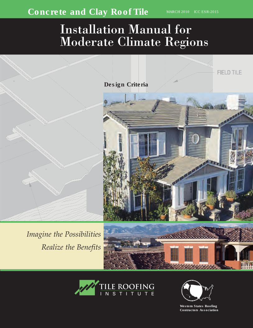
Design Criteria
Imagine the Possibilities
Realize the Benefits
Concrete and Clay Roof Tile MARCH 2010 ICC ESR-2015
Western States Roofing Contractors Association
Installation Manual forModerate Climate Regions

TRI/WSRCA
PRINTED IN THE U.S.A.
COPYRIGHT © TILE ROOFING INSTITUTE\WSRCA ICC-ES ESR-2015 01/2000 Revised 3/2010
FOREWORD
The Tile Roofing Institute (TRI) is the premier resource for technical information on the proper design andinstallation of concrete and clay roof tile systems. The Tile Roofing Institute in partnership with theWestern States Roofing Contractors Association (WSRCA) assembled a task group in 1991 to develop aninstallation manual that would provide a representation proper installation practices, industry standards,and code requirements. These recommendations have provided successful installations of roof tile whichhave endured the test of time.
During the last year the TRI and WSRCA technical committees reviewed the existing 2006 manual andsolicited valuable input from the entire roofing community. The culmination of those efforts has been thecreation of the 2010 Edition of the Installation Manual for Moderate Climate Regions. As with the previ-ous editions, the TRI has submitted the manual for formal review and issuance of an ICC-ES EvaluationReport number ICC-ES- ESR 2015P to help provide a stronger foundation to the formal practices and rec-ommendations included in this manual.
The Tile Roofing Institute offers additional installation manuals Concrete and Clay Tile Roof Design CriteriaManual for Cold and Snow Regions and FRSA/TRI Concrete and Clay Roof Tile Installation Manual. Allof our publications can be ordered through the publication page on our website (www.tileroofing.org).The TRI will be offering formal installer training programs based upon the manuals to allow roofing pro-fessionals to become certified tile installers.
TRI continues to provide the leading edge technology for roof innovations that will provide the highestquality, energy efficient roofing systems available in the market today. Tile roofing systems provide one ofthe most durable, energy efficient roofing systems found anywhere in the world.
Updates and Bulletins - The Tile Roofing Institute would like to make sure that we provide the latest infor-mation and updates available directly to you. If you would like to receive notices of any changes, updates,or provide comments on this manual please visit our website www.tileroofing.org or email us [email protected] and ask to be placed on our email listing for future notices.
LIMITATIONS ON USE AND DISCLAIMER FOR THIS TRI/WSRCA INSTALLATION MANUAL
These drawings and recommendations are the compilation of the individual experiences of industry mem-bers and the Technical Committee of the TRI/WSRCA. It is intended to be used with the judgment andexperience of professional personnel competent to evaluate the significance and limitations of the materialcontained and who will accept responsibility for its application. The TRI/WSRCA expressly disclaims anyguarantees or warranties, expressed or implied, for anything described or illustrated herein; and assumesno responsibility for error or omissions.
TRI/WSRC
TABLE OF CONTENTSIntroduction . . . . . . . . . . . . . . . . . . . . . . . . . . . . . . . . . . . . . . . . . . . . . . . . . . . . . . . . . . . . . . . . . . . . . . . . . . . . . . . . .1
Tools Required . . . . . . . . . . . . . . . . . . . . . . . . . . . . . . . . . . . . . . . . . . . . . . . . . . . . . . . . . . . . . . . . . . . . . . . . . . . .1Safety Warning - Tile Dust/Governing Bodies/Environmental Statement . . . . . . . . . . . . . . . . . . . . . . . . . . . . .2Specifications . . . . . . . . . . . . . . . . . . . . . . . . . . . . . . . . . . . . . . . . . . . . . . . . . . . . . . . . . . . . . . . . . . . . . . . . . . . . . .3 -6
Suggested Material Checklist/Roof Tile Classifications . . . . . . . . . . . . . . . . . . . . . . . . . . . . . . . . . . . . . . . . . . . . .3Tile Specifications/Materials and Manufacture . . . . . . . . . . . . . . . . . . . . . . . . . . . . . . . . . . . . . . . . . . . . . . . . .4 - 6
Installation . . . . . . . . . . . . . . . . . . . . . . . . . . . . . . . . . . . . . . . . . . . . . . . . . . . . . . . . . . . . . . . . . . . . . . . . . . . . . . .7 - 14General Information . . . . . . . . . . . . . . . . . . . . . . . . . . . . . . . . . . . . . . . . . . . . . . . . . . . . . . . . . . . . . . . . . . . . . . .7New Construction . . . . . . . . . . . . . . . . . . . . . . . . . . . . . . . . . . . . . . . . . . . . . . . . . . . . . . . . . . . . . . . . . . . . . .8 - 9Reroofing . . . . . . . . . . . . . . . . . . . . . . . . . . . . . . . . . . . . . . . . . . . . . . . . . . . . . . . . . . . . . . . . . . . . . . . . . . . . . . . .9Ventilation Guidelines . . . . . . . . . . . . . . . . . . . . . . . . . . . . . . . . . . . . . . . . . . . . . . . . . . . . . . . . . . . . . . . . . . . . . .9Table 1A Roof Tile Application . . . . . . . . . . . . . . . . . . . . . . . . . . . . . . . . . . . . . . . . . . . . . . . . . . . . . . . . . . . . . .10Table 1B Roof Tile Application . . . . . . . . . . . . . . . . . . . . . . . . . . . . . . . . . . . . . . . . . . . . . . . . . . . . . . . . . . . . . .11Table 2 Batten Allowable Loads . . . . . . . . . . . . . . . . . . . . . . . . . . . . . . . . . . . . . . . . . . . . . . . . . . . . . . . . . . . . .12Table 3 Guidelines for Battens . . . . . . . . . . . . . . . . . . . . . . . . . . . . . . . . . . . . . . . . . . . . . . . . . . . . . . . . . . . . . .13Table 4 Roof Slope Conversion . . . . . . . . . . . . . . . . . . . . . . . . . . . . . . . . . . . . . . . . . . . . . . . . . . . . . . . . . . . . . .14Table 5 Metric Conversion . . . . . . . . . . . . . . . . . . . . . . . . . . . . . . . . . . . . . . . . . . . . . . . . . . . . . . . . . . . . . . . . .14
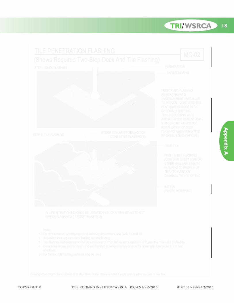
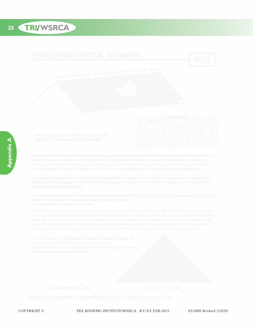
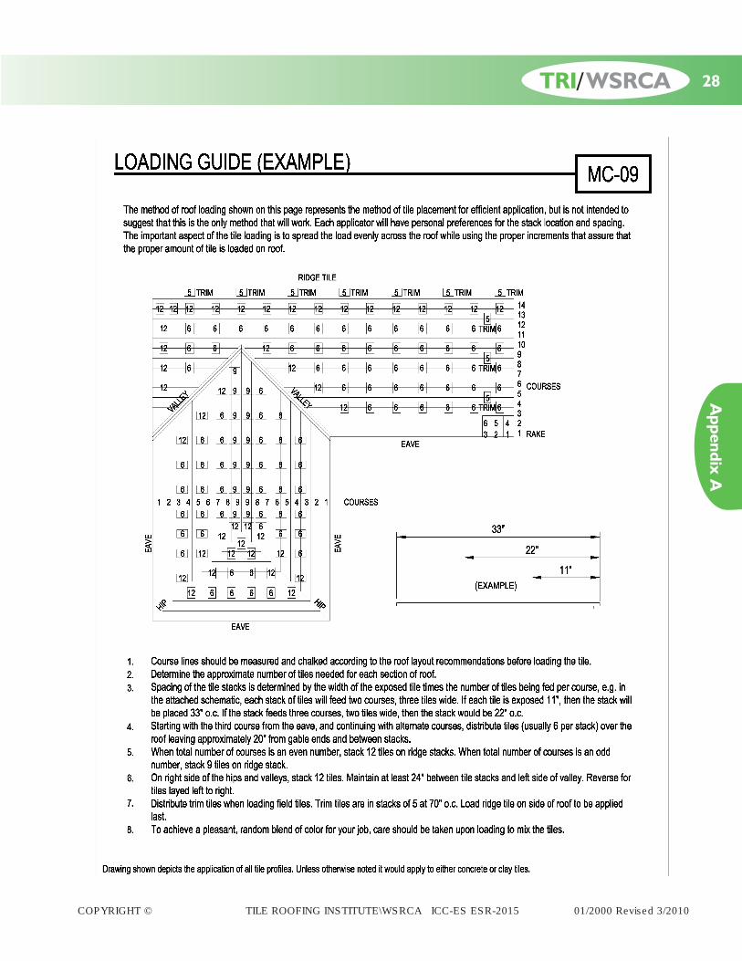
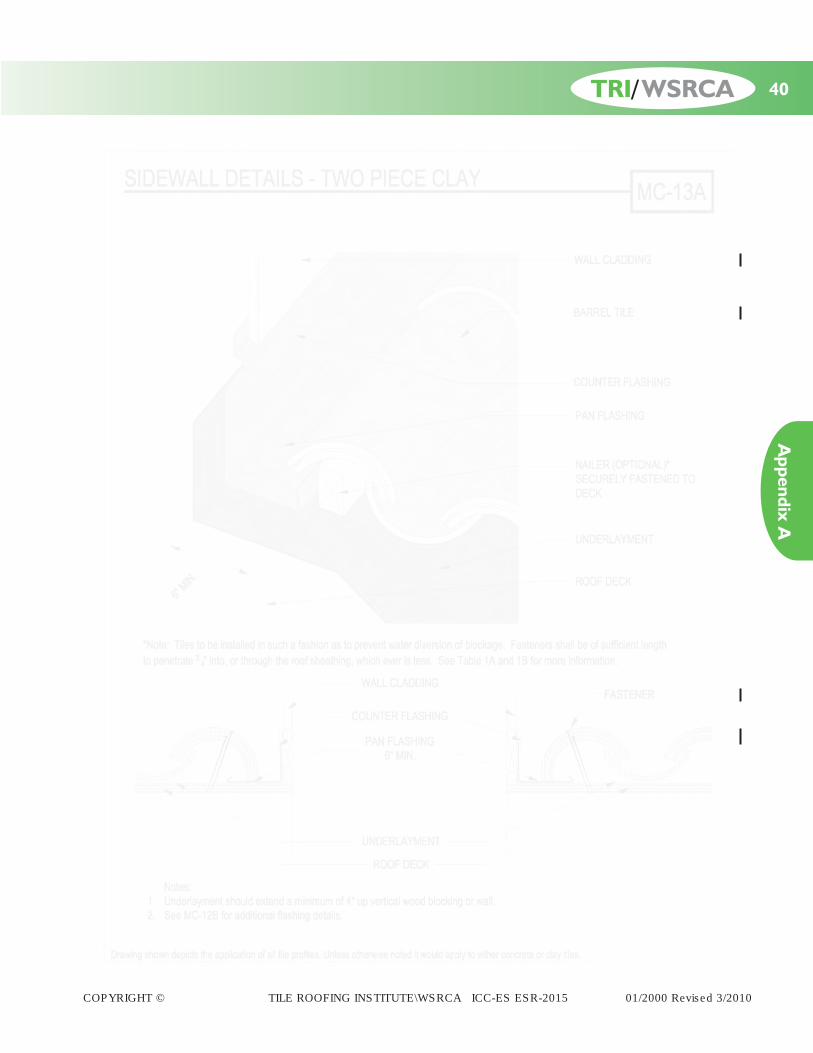
Appendix A - Installation Detail Drawings . . . . . . . . . . . . . . . . . . . . . . . . . . . . . . . . . . . . . . . . . . . . . . . . . . . . .15 - 74Identification of Roof Areas . . . . . . . . . . . . . . . . . . . . . . . . . . . . . . . . . . . . . . . . . . . . . . . . . . . . . . . . . . . . . . . . .15Single-Layer Underlayment . . . . . . . . . . . . . . . . . . . . . . . . . . . . . . . . . . . . . . . . . . . . . . . . . . . . . . . . . . . . . . . . .16Double Layer Underlayment . . . . . . . . . . . . . . . . . . . . . . . . . . . . . . . . . . . . . . . . . . . . . . . . . . . . . . . . . . . . . . . .17Tile Penetration Flashing . . . . . . . . . . . . . . . . . . . . . . . . . . . . . . . . . . . . . . . . . . . . . . . . . . . . . . . . . . . . . . . . . . .18Valley Underlayments (Woven Underlayment) . . . . . . . . . . . . . . . . . . . . . . . . . . . . . . . . . . . . . . . . . . . . . . . . . .19Valley Underlayments (Overlapping Underlayment) . . . . . . . . . . . . . . . . . . . . . . . . . . . . . . . . . . . . . . . . . . . . . .20Batten Layout Options . . . . . . . . . . . . . . . . . . . . . . . . . . . . . . . . . . . . . . . . . . . . . . . . . . . . . . . . . . . . . . . . . . . .21Counterbatten Installation . . . . . . . . . . . . . . . . . . . . . . . . . . . . . . . . . . . . . . . . . . . . . . . . . . . . . . . . . . . . . . . . . .22Vertical Battens - For Deep Trough Valley . . . . . . . . . . . . . . . . . . . . . . . . . . . . . . . . . . . . . . . . . . . . . . . . . . . . .23Vertical Battens - For Standard Valley and Hips . . . . . . . . . . . . . . . . . . . . . . . . . . . . . . . . . . . . . . . . . . . . . . . . .24Establishing Vertical Alignment . . . . . . . . . . . . . . . . . . . . . . . . . . . . . . . . . . . . . . . . . . . . . . . . . . . . . . . . . . . . . .25Roof Layout . . . . . . . . . . . . . . . . . . . . . . . . . . . . . . . . . . . . . . . . . . . . . . . . . . . . . . . . . . . . . . . . . . . . . . . . . . . . .26Roof Layout - Quick Reference . . . . . . . . . . . . . . . . . . . . . . . . . . . . . . . . . . . . . . . . . . . . . . . . . . . . . . . . . . . . . .27Suggested Loading Guide . . . . . . . . . . . . . . . . . . . . . . . . . . . . . . . . . . . . . . . . . . . . . . . . . . . . . . . . . . . . . . . . . .28Down Slope Eave Details . . . . . . . . . . . . . . . . . . . . . . . . . . . . . . . . . . . . . . . . . . . . . . . . . . . . . . . . . . . . . . . . . .29Raised Fascia . . . . . . . . . . . . . . . . . . . . . . . . . . . . . . . . . . . . . . . . . . . . . . . . . . . . . . . . . . . . . . . . . . . . . . . . . . . .30Eave At Flush Wall or Fascia/Zero Overhang . . . . . . . . . . . . . . . . . . . . . . . . . . . . . . . . . . . . . . . . . . . . . . . . . . .31Low Slope/Ventilated Roof Eave Detail . . . . . . . . . . . . . . . . . . . . . . . . . . . . . . . . . . . . . . . . . . . . . . . . . . . . . . . .32Double Lap Tile (Non-Interlocking) . . . . . . . . . . . . . . . . . . . . . . . . . . . . . . . . . . . . . . . . . . . . . . . . . . . . . . . . . .33Head Wall Metal Flashing (With Counterflashing) . . . . . . . . . . . . . . . . . . . . . . . . . . . . . . . . . . . . . . . . . . . . . . . .34Head Wall Metal Flashing (Without Counterflashing) . . . . . . . . . . . . . . . . . . . . . . . . . . . . . . . . . . . . . . . . . . . . .35Pan Flashing At Roof-To-Sidewall (Where Wall Extends Past Eave With Counterflashing) . . . . . . . . . . . . . . . . .36Pan Flashing At Roof-To-Sidewall (Where Wall Extends Past Eave) . . . . . . . . . . . . . . . . . . . . . . . . . . . . . . . . . .37Metal Flashing Options . . . . . . . . . . . . . . . . . . . . . . . . . . . . . . . . . . . . . . . . . . . . . . . . . . . . . . . . . . . . . . . . . . . .38Sidewall Details - Clay ‘S’ Tile . . . . . . . . . . . . . . . . . . . . . . . . . . . . . . . . . . . . . . . . . . . . . . . . . . . . . . . . . . . . . . .39Sidewall Details - Two Piece Clay . . . . . . . . . . . . . . . . . . . . . . . . . . . . . . . . . . . . . . . . . . . . . . . . . . . . . . . . . . . .40Chimney Flashing - Pan Type . . . . . . . . . . . . . . . . . . . . . . . . . . . . . . . . . . . . . . . . . . . . . . . . . . . . . . . . . . . . . . . .41Chimney Flashing - Step Type . . . . . . . . . . . . . . . . . . . . . . . . . . . . . . . . . . . . . . . . . . . . . . . . . . . . . . . . . . . . . . .42Chimney Cricket Flashing - Pan Type . . . . . . . . . . . . . . . . . . . . . . . . . . . . . . . . . . . . . . . . . . . . . . . . . . . . . . . . .43
COPYRIGHT © TILE ROOFING INSTITUTE\WSRCA ICC-ES ESR-2015 01/2000 Revised 3/2010
TRI/WSRCA
Chimney Cricket Flashing - Step Type . . . . . . . . . . . . . . . . . . . . . . . . . . . . . . . . . . . . . . . . . . . . . . . . . . . . . . . .44Skylight Underlayment Detail . . . . . . . . . . . . . . . . . . . . . . . . . . . . . . . . . . . . . . . . . . . . . . . . . . . . . . . . . . . . . . .45Skylight Flashing - Pan Type . . . . . . . . . . . . . . . . . . . . . . . . . . . . . . . . . . . . . . . . . . . . . . . . . . . . . . . . . . . . . . . . .46Skylight Step Flashing . . . . . . . . . . . . . . . . . . . . . . . . . . . . . . . . . . . . . . . . . . . . . . . . . . . . . . . . . . . . . . . . . . . . . .47Open Valley - Tile Installed With Gap At Valley Metal . . . . . . . . . . . . . . . . . . . . . . . . . . . . . . . . . . . . . . . . . . . .48Three Rib Valley Metal Profiles . . . . . . . . . . . . . . . . . . . . . . . . . . . . . . . . . . . . . . . . . . . . . . . . . . . . . . . . . . . . . .49Valley Metal - For Deep Trough Valley . . . . . . . . . . . . . . . . . . . . . . . . . . . . . . . . . . . . . . . . . . . . . . . . . . . . . . . .50Valley Transitions . . . . . . . . . . . . . . . . . . . . . . . . . . . . . . . . . . . . . . . . . . . . . . . . . . . . . . . . . . . . . . . . . . . . . . . . .51Boxed-in Soffit . . . . . . . . . . . . . . . . . . . . . . . . . . . . . . . . . . . . . . . . . . . . . . . . . . . . . . . . . . . . . . . . . . . . . . . . . . .52Hip And Ridge A . . . . . . . . . . . . . . . . . . . . . . . . . . . . . . . . . . . . . . . . . . . . . . . . . . . . . . . . . . . . . . . . . . . . . . . . .53Hip And Ridge B . . . . . . . . . . . . . . . . . . . . . . . . . . . . . . . . . . . . . . . . . . . . . . . . . . . . . . . . . . . . . . . . . . . . . . . . .54Vented Ridge (Option) . . . . . . . . . . . . . . . . . . . . . . . . . . . . . . . . . . . . . . . . . . . . . . . . . . . . . . . . . . . . . . . . . . . .55Parapet Or Mansard Condition . . . . . . . . . . . . . . . . . . . . . . . . . . . . . . . . . . . . . . . . . . . . . . . . . . . . . . . . . . . . . .56Rake Flashing - Counter Batten System . . . . . . . . . . . . . . . . . . . . . . . . . . . . . . . . . . . . . . . . . . . . . . . . . . . . . . .57Rake Flashing - Options . . . . . . . . . . . . . . . . . . . . . . . . . . . . . . . . . . . . . . . . . . . . . . . . . . . . . . . . . . . . . . . . . . .58Rake Tile Installation . . . . . . . . . . . . . . . . . . . . . . . . . . . . . . . . . . . . . . . . . . . . . . . . . . . . . . . . . . . . . . . . . . . . . .59Gable / Eave Installation - Barrel Tile . . . . . . . . . . . . . . . . . . . . . . . . . . . . . . . . . . . . . . . . . . . . . . . . . . . . . . . . .60Gable / Eave Installation . . . . . . . . . . . . . . . . . . . . . . . . . . . . . . . . . . . . . . . . . . . . . . . . . . . . . . . . . . . . . . . . . . .61Roof Vents (Off Ridge) . . . . . . . . . . . . . . . . . . . . . . . . . . . . . . . . . . . . . . . . . . . . . . . . . . . . . . . . . . . . . . . . . . . . .62Slope Change Applications . . . . . . . . . . . . . . . . . . . . . . . . . . . . . . . . . . . . . . . . . . . . . . . . . . . . . . . . . . . . . . . . .63Gutters . . . . . . . . . . . . . . . . . . . . . . . . . . . . . . . . . . . . . . . . . . . . . . . . . . . . . . . . . . . . . . . . . . . . . . . . . . . . . . . .64Tile Repairs / Replacement . . . . . . . . . . . . . . . . . . . . . . . . . . . . . . . . . . . . . . . . . . . . . . . . . . . . . . . . . . . . . . . . .65Tile Repairs / Replacement - Continued . . . . . . . . . . . . . . . . . . . . . . . . . . . . . . . . . . . . . . . . . . . . . . . . . . . . . . .66Specialty Conditions- Pre-Engineered Roof (Installation on Metal Deck - Considerations) . . . . . . . . . . . . . . . .67Specialty Conditions- Pre-Engineered Roof (Installation on Metal Deck - Optional Considerations) . . . . . . . .68Specialty Conditions- Pre-Engineered Roof (Installation on Metal Deck - Optional Considerations) . . . . . . . .69Specialty Conditions- Pre-Engineered Roof (Installation on Metal Deck - Optional Considerations) . . . . . . . .70Specialty Conditions- Pre-Engineered Deck (Installation on Concrete Deck Considerations) . . . . . . . . . . . . .71Specialty Conditions- Pre-Engineered Deck (Installation on Concrete Deck Considerations) . . . . . . . . . . . . .72Specialty Conditions- Pre-Engineered Roof (Wire Attachment System) . . . . . . . . . . . . . . . . . . . . . . . . . . . . . .73Specialty Conditions- Pre-Engineered Roof (Wire Attachment System) . . . . . . . . . . . . . . . . . . . . . . . . . . . . . .74Specialty Conditions- Nailer Installations . . . . . . . . . . . . . . . . . . . . . . . . . . . . . . . . . . . . . . . . . . . . . . . . . . . . . .75
Appendix B - Specialty installations . . . . . . . . . . . . . . . . . . . . . . . . . . . . . . . . . . . . . . . . . . . . . . . . . . . . . . . . . . .76 - 86Draped Underlayment Applications . . . . . . . . . . . . . . . . . . . . . . . . . . . . . . . . . . . . . . . . . . . . . . . . . . . . . . . . . .76Installation of Underlayments Under Spaced Sheathing . . . . . . . . . . . . . . . . . . . . . . . . . . . . . . . . . . . . . . . . . . .76Adhesive Fastening Systems . . . . . . . . . . . . . . . . . . . . . . . . . . . . . . . . . . . . . . . . . . . . . . . . . . . . . . . . . . . . . . . .77Design Considerations for High Wind Applications . . . . . . . . . . . . . . . . . . . . . . . . . . . . . . . . . . . . . . . . . .77 - 79Design Considerations for High Wind Applications Table 5A . . . . . . . . . . . . . . . . . . . . . . . . . . . . . . . . . . . . . . .79Design Considerations for High Wind Applications Tables 5B & 5C . . . . . . . . . . . . . . . . . . . . . . . . . . . . . . . . .80Design Considerations for High Wind Applications Tables 5D & 6A . . . . . . . . . . . . . . . . . . . . . . . . . . . . . . . . .81Design Considerations for High Wind Applications Table 6B & 6C . . . . . . . . . . . . . . . . . . . . . . . . . . . . . . . . . .82Design Considerations for High Wind Applications Table 6D, 6E, & 6F . . . . . . . . . . . . . . . . . . . . . . . . . . . . . .83Allowable Aerodynamic Uplift Moments Mechanical Fastening Systems Table 7A . . . . . . . . . . . . . . . . . . . . . .84Allowable Aerodynamic Uplift Moments Mechanical Fastening Systems Table 7A cont’d . . . . . . . . . . . . . . . . .85Allowable Aerodynamic Uplift Moments Mechanical Fastening Systems Notes . . . . . . . . . . . . . . . . . . . . . . . .86Design Considerations for Installations in Earthquake Regions . . . . . . . . . . . . . . . . . . . . . . . . . . . . . . . . . . . . .86
Appendix C - Glossary of Terms . . . . . . . . . . . . . . . . . . . . . . . . . . . . . . . . . . . . . . . . . . . . . . . . . . . . . . . . . . . . .87 - 89
COPYRIGHT © TILE ROOFING INSTITUTE\WSRCA ICC-ES ESR-2015 01/2000 Revised 3/2010
Since tile is installed across a wide range of climatic andgeographic conditions, there are a variety of details thatmust be considered in preparing an effective installation.The minimum recommendations shown for moderateregions are effective for a relatively wide range of condi-tions including occasional storms or snow. While it is notpractical to prescribe precise solutions for all conditions,the following has been provided to offer suggestions forvarious treatments in a moderate climate application. Localbuilding officials should always be consulted to learn ofspecial requirements that may exist. Some of the changescontained will require code approval.
This manual provides the minimum design recommenda-tions with optional upgrades for the installation of under-layment, flashings, fastening and related measures toprovide a weather resistant roofing assembly for concreteand clay tile.
Designers should be familiar with local climatic conditionsand make sure that they are reviewing the proper designmanual. Please see the following list of reference publica-tions for additional information.
INTRODUCTION
These recommendations are meant for areas with moder-ate climates that may experience occasional storms, butnot regular repetitive freeze thaw cycling. In locationswhere the January mean temperature is 25 deg. F (-4 degC) or less or where ice damming often occurs, the TRI/WSRCA suggests reference to the Concrete and ClayTile Roof Design Criteria Manual for Cold and SnowRegions. While generally considered the minimum stan-dard, proper adherence to these recommendations andattention to detail and workmanship provide a functionalroof in most all moderate climate conditions. Local buildingofficials should be consulted for engineering criteria orother special requirements.
The manner in which tile roofs are installed makes thema highly effective water shedding assembly that affordsyears of service and protection. The effectiveness of a tileroof system as a weather resistant assembly howeverdepends on the proper installation of all the tile roofcomponents, and installing them properly is critical to theperformance of the installed system.
1
TOOLS REQUIRED (Other items may be required per field conditions)
Basic Hand ToolsTape Measure Crayon HammerTin Snips Felt Knife Nail BagChalkline Chalk Pry BarMetal Crimper Mortar Trowel Mastic trowelCaulking Gun Hand Saw RollerBrush Broom
Specialty Tools & EquipmentForklift Conveyor Tile CutterLadder Tile Nippers
Introduction
TRI/WSRCA
COPYRIGHT © TILE ROOFING INSTITUTE\WSRCA ICC-ES ESR-2015 01/2000 Revised 3/2010
Power Tools
Drill 3/16” Masonry Bit Screw GunPower Cords Compressor w/ Hose Nail GunTile Saw Diamond Saw Blade
Safety & Personal Protective Equipment Per Federal & State OSHA Requirements
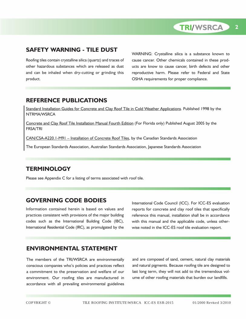
REFERENCE PUBLICATIONSStandard Installation Guides for Concrete and Clay Roof Tile in Cold Weather Applications. Published 1998 by theNTRMA/WSRCA
Concrete and Clay Roof Tile Installation Manual Fourth Edition (For Florida only) Published August 2005 by the FRSA/TRI
CAN/CSA-A220.1-M91 – Installation of Concrete Roof Tiles, by the Canadian Standards Association
The European Standards Association, Australian Standards Association, Japanese Standards Association
TERMINOLOGYPlease see Appendix C for a listing of terms associated with roof tile.
GOVERNING CODE BODIES Information contained herein is based on values andpractices consistent with provisions of the major buildingcodes such as the International Building Code (IBC),International Residential Code (IRC), as promulgated by the
The members of the TRI/WSRCA are environmentallyconscious companies who’s policies and practices reflecta commitment to the preservation and welfare of ourenvironment. Our roofing tiles are manufactured inaccordance with all prevailing environmental guidelines
International Code Council (ICC). For ICC-ES evaluationreports for concrete and clay roof tiles that specificallyreference this manual, installation shall be in accordancewith this manual and the applicable code, unless other-wise noted in the ICC-ES roof tile evaluation report.
and are composed of sand, cement, natural clay materialsand natural pigments. Because roofing tile are designed tolast long term, they will not add to the tremendous vol-ume of other roofing materials that burden our landfills.
ENVIRONMENTAL STATEMENT
2
SAFETY WARNING - TILE DUST
Roofing tiles contain crystalline silica (quartz) and traces ofother hazardous substances which are released as dustand can be inhaled when dry-cutting or grinding thisproduct.
WARNING: Crystalline silica is a substance known tocause cancer. Other chemicals contained in these prod-ucts are know to cause cancer, birth defects and otherreproductive harm. Please refer to Federal and StateOSHA requirements for proper compliance.
TRI/WSRCA
COPYRIGHT © TILE ROOFING INSTITUTE\WSRCA ICC-ES ESR-2015 01/2000 Revised 3/2010

Roof To Wall: Minimum 3" coverage over tile or flexible flashing. See Table A on page 4 for more details.
Pipe Flashing: Deck & Tile flashing is required. Profile tile flashing to be malleable metal flashings. See Table A on page 4 for more details.
In wall Counter Flashing: Z bar recommended or surface
mount reglet (pin) Flashing forre-roof. See Table A for more details.
Fasteners: See page 6 and Table 1A/1B for requirements.
Ventilation: Per local building code requirements.
Decking: Sheathing must be adequate tosupport the loads involved, but not less than nominal 1-inch-thick lumber or nominal 15/32-inch-thick plywood or other decking material recognized in a code evaluation report or by the local building official.
Underlayment: ASTM D226 Type II (No. 30 felt)/ASTM D4869 Type IV or ASTM D1970 (self adhering), meeting AC 150.
Battens: Nominal 1" x 2" complying with IBCChapter 23, section 2302 (nominal size).
Eave Treatments: Bird Stop/Eave riser.
Valley Flashing: Shall extend each way 11" fromcenter and have a splash diverter rib 1" high. See Table A on page 4 for more details.
Wall Trays (Pans): Minimum 6" trough. See Table A onpage 4 for more details.
MATERIAL CHECKLIST(Other options/upgrades may be allowed per codes)
ROOF TILE•CLASSIFICATIONSRoof tiles manufactured are typically of the following types:
Low Profile Tile – Tiles, such as flat tile that have a top surface rise of ½” or less.
Medium Profile Tile – Tiles having a rise to width ratio equal to or less than 1:5
High Profile Tile – Tiles having a rise to width ratio greater than 1:5 (measured in installed condition)
Accessory Tile – Shall include those tile such as ridge, rake, hip, valley and starter tile used in conjunction with thosetile listed above.
3 TRI/WSRCA
Specifications
Clay Tile
Clay Tile
Clay Tile
Concrete Tile
Concrete Tile
Concrete Tile
1/2"
H
H
W
W
COPYRIGHT © TILE ROOFING INSTITUTE\WSRCA ICC-ES ESR-2015 01/2000 Revised 3/2010

4
Specifications
TRI/WSRCA
COPYRIGHT © TILE ROOFING INSTITUTE\WSRCA ICC-ES ESR-2015 01/2000 Revised 3/2010
REFERENCE TABLE FOR DRAWING DETAILS
TYPE SPECIFICATIONS DETAILS
VALLEY FLASHING MC-12B, MC-17, MC-17A, MC-17B
PAN FLASHINGCHANNEL FLASHING MC-12, MC-12A, MC-12B, MC-13, MC-13AWALL TRAYS FLASHING
HEADWALL FLASHINGROOF TO WALL FLASHING MC-11, MC-11AAPRON FLASHING
COUNTER FLASHING NO. 26 GALVANIZED SHEET GAUGEZ BAR FLASHING
NOT LESS THAN 0.019"DRIP EDGE FLASHINGEAVE FLASHING ASTM A653
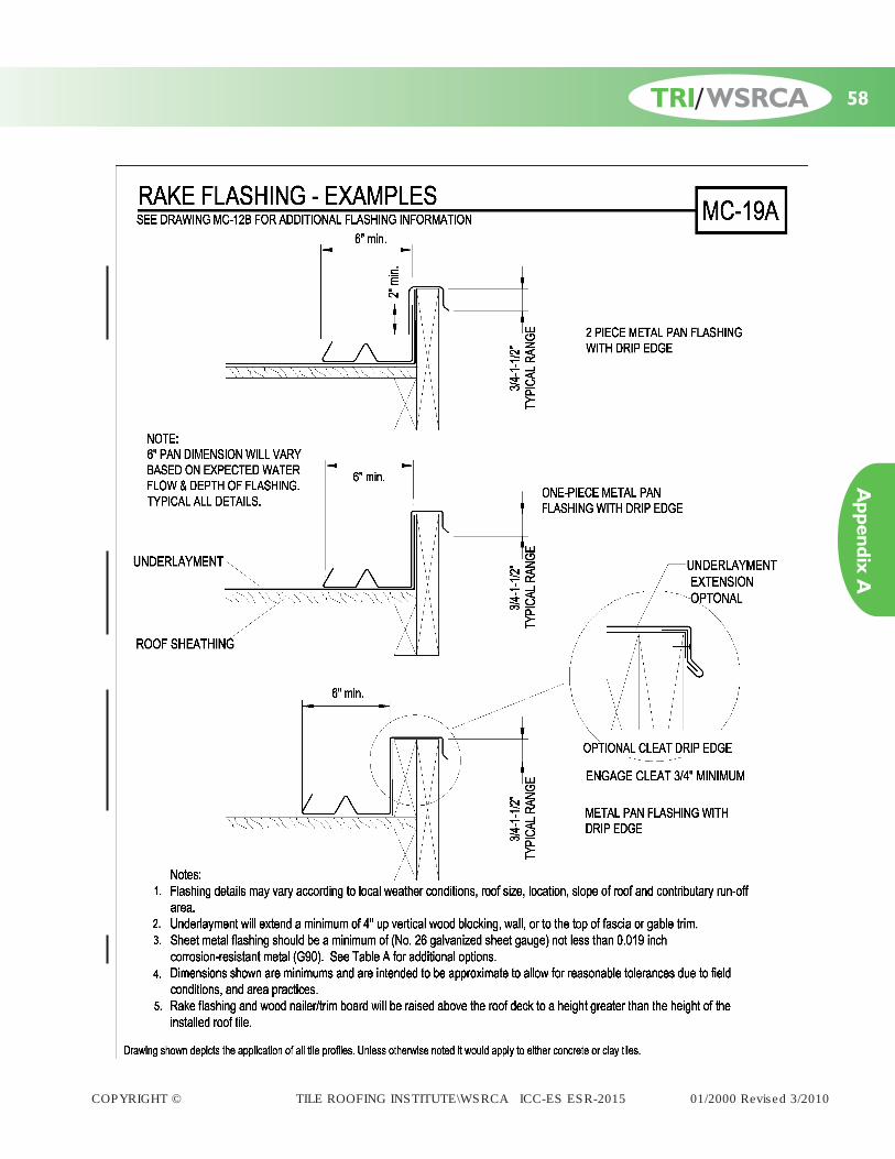
RAKE FLASHING G90 MC-12B, MC-19, MC-19A
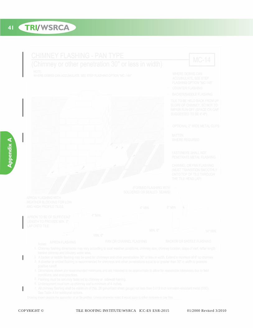
CHIMNEY FLASHINGSKYLIGHT FLASHING MC-14, MC-14A, MC-15, MC-15A, MC-16A, MC-16BSADDLE FLASHING
PIPE FLASHINGDECK FLASHING
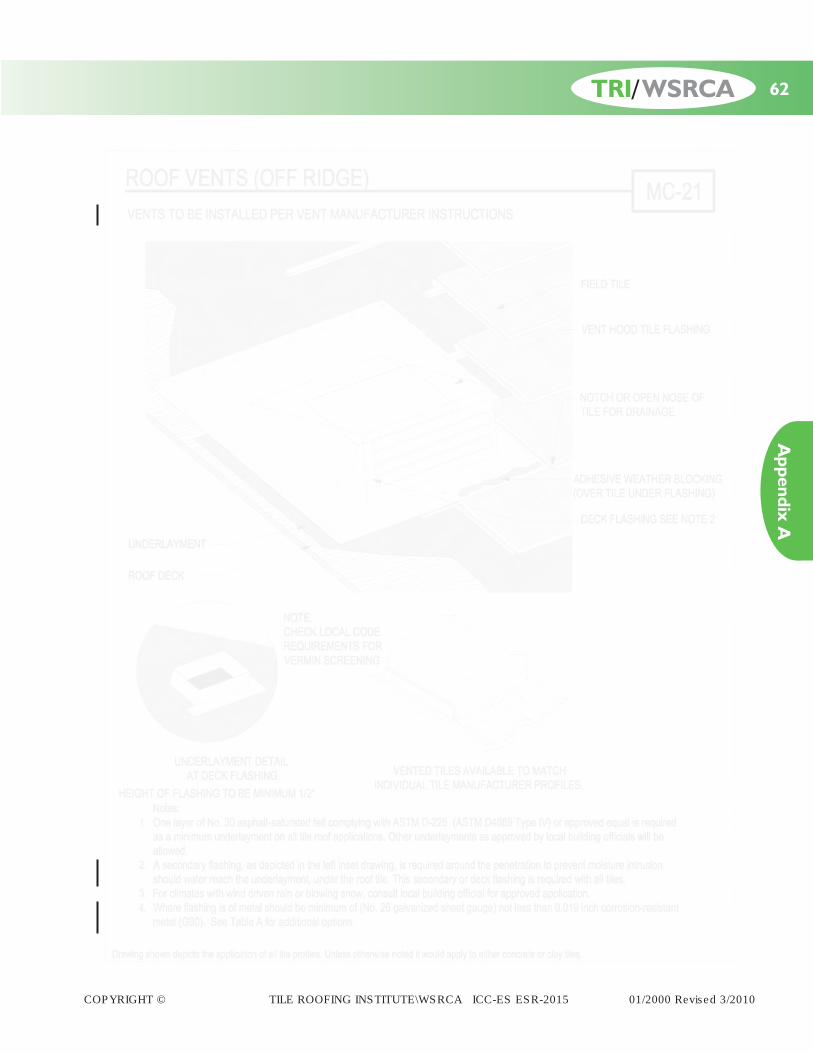
ROOF VENTSATTIC VENTS
SOFT LEAD NOT LESS THAN 3 LBS / SQ.FTPROFILE TILE FLASHING DEAD SOFT ALUMINUM NOT LESS THAN 0.019" MC-02
SOFT COPPER NOT LESS THAN 16 OZ/SQ.FT
ACCESSORIES
TYPE SPECIFICATIONS DETAILS
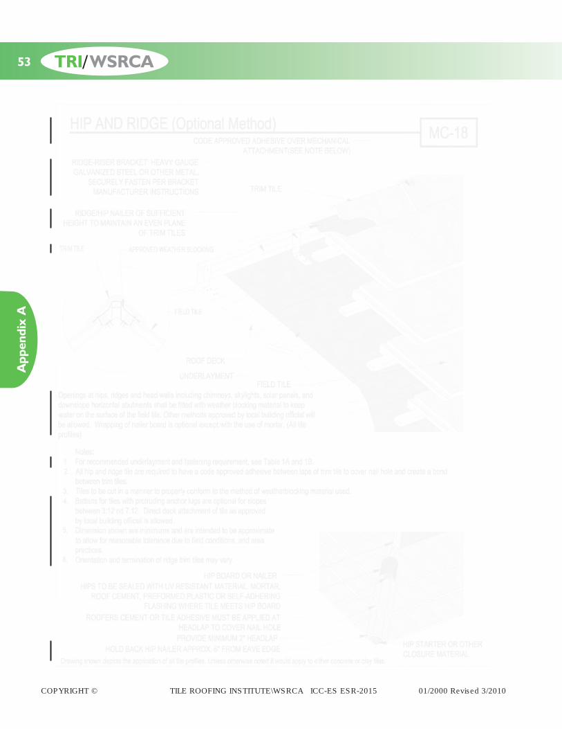
BIRDSTOP MC-10A, MC-10B, MC-10C, MC-23, MC-25EAVE RISER PER MANUFACTURER PER MANUFACTURER’S SPECIFICATIONSWEATHER BLOCKING MC-18, MC-18A, MC-18B
* All flashings above are considered minimums.* For other special metal type upgrades see IBC Tables 1507.4.3(1) and 1507.4.3(2) or lRC Tables R 905.10.3(1) and R 905.10.3(2), as applicable.
TABLE A
MC-11, MC-12, MC-13, MC-13A
MC-10, MC-10A, MC-10B, MC-10C, MC-10D
MC-02, MC-21
MC-21

TILE SPECIFICATIONS/RECOMMENDATIONS
Freeze Thaw – Different climatic conditions will result inthe need for different roofing materials that will allow thesuccess of the roofing system over the long-term.Resistance to freeze/thaw is very important in weatheringsituations where the roofing material is expected to with-stand repetitive freezing and thawing cycles. BothConcrete and Clay Tile must have passed the require-ments of ASTM C1492 (Concrete) ASTM C1167 (Clay) forfreeze thaw regions.
Strength – A Concrete (ASTM C1492) or Clay tile’s(ASTM C1167) transverse strength will meet or exceedrequirements of the specified codes.
Thickness – Roof tile typically ranges in thickness from3/8" to 11/2", depending upon composition, type and style.
Quantities of Tile Per Square – The size of the tile andthe exposure of each course of tile determines the numberof tile needed to cover one square (100 sq. ft.) of roof area.When the tile is installed at the manufacturer’s maximumexposure, the number of tile needed to cover one squareof roof area may range from 75 to over 400 pieces.
Tile Weight – The size of the tile and the exposure ofeach course will determine the installed weight of the rooftile. In general, the amount of tile to cover one square(100 sq ft.) set at the standard 3 inch head lap, will dependon the thickness, length, width, shape and aggregatematerials used in the manufacturing process of the tile.Please consult with the tile manufacturer when determin-ing the weight of the specific tile that will be used. As withany roofing material the designer should always considerthe weight of the underlayment, fastening system, roofaccessories and special hip/ridge treatments.
MATERIALS AND MANUFACTURE
Concrete Tile – Cementitious materials such as portlandcement, blended hydraulic cements and fly ash, sand, raw orcalcined natural pozzolans and aggregates shall conform to thefollowing applicable ASTM specifications.
Concrete Tile ASTM C1492 Specifications –Portland Cement – Specification C150 or Performance Specification C1157Modified Portland Cement – Specification C90Blended Cement – Specification C595 Pozzolans – Specification C618Ground Granulated Blast Furnace Slag – Specification C989
Aggregates such as normal weight and lightweightshall conform to the following ASTM specifications;except that grading requirements do not apply.Normal Weight Aggregates – Specification C33Lightweight Aggregates – Specification C331
Clay Tile – Tiles are manufactured from clay, shale, orother similar naturally occurring earthly substances andsubjected to heat treatment at elevated temperatures (fir-ing). The heat treatment must develop a fired bondbetween the particulate constituents to provide thestrength and durability requirements.
Clay Tile ASTM C1167 Specifications –
Terminology for structural clay products – C43Test methods and sampling and testing brick and
structural clay – C67Test methods for tensile strength of flat sandwich
construction in flat wise plane – C297Test method for crazing resistance of fired glazed
ceramic whitewares by thermal shock method – C 554
Additional Standards for Concrete & Clay Tile maybe referenced in the following additional standards:
ASCE-7 Uniform Building CodeIBC/IRC ICC-ES AC 152 Acceptance CriteriaStandard Building Code CAN/CSA – A220.1-M91ICC-ES AC180 Acceptance Criteria
Adhesive – Bonding materials designed to stick tiles totiles, or tiles to a substrate and can include mortar, syn-thetic mortar, mastics, silicones, polymers, Trig-polymers,or other materials approved by the local building official.Contact the adhesive manufacturer for additional informa-tion. Refer to current ICC-ES evaluation reports of rooftile adhesives for installation requirements and conditionsof use.
Batten – A sawed strip of wood installed horizontally andparallel to the eave line which is mechanically attached to
COPYRIGHT © TILE ROOFING INSTITUTE\WSRCA ICC-ES ESR-2015 01/2000 Revised 3/2010
5 TRI/WSRCA
Specifications

the roof deck or rafters to engage the anchor lugs to preventslippage of the roof tile. Battens of nominal 1"x2" lumbercomplying with IBC Chapter 23, section 2302 may bedimensionally increased in size to accommodate structuralloads for snow or unsupported spans over counter battensor rafters. Battens may also be corrosion resistant metal,or other man-made material that meets the approval ofthe local building official. In dry/low humidity climatesmoisture resistant battens are not required. See Tables 1Aand 1B on pages 10 and 11.
Battens installed over counter battens or which span overrafters commonly are of soft wood, spruce, pine, or firtype species but may be of any type of lumber, metal orman-made materials that meet the approval of thelocal building official. See table 2 on page 12.
Counter Battens – Additional set of battens installedvertically and parallel to the roof slope and mechanicallyattached to the roof deck under the batten. Counterbattens are commonly 1/4 inch lath but may be dimen-sionally increased in size to provide a greater flow of airor moisture beneath the horizontal battens. Counterbattens do not need to be of moisture resistant lumber asthey do not impede moisture flow. Counter battens mayalso be of corrosion resistant metal or other man-madematerials that meet the approval of the local buildingofficial. See table 2 on page 12.
Note: If counter battens are installed under the underlay-ment, caution must be used to prevent damage to underlay-ment or reinforced underlayment shall be used.
Note: Care should be taken in selecting the proper battendesign. Excessive deflection of the batten may lead to tilebreakage. See table 2 on page 12.
Caulking and Sealant
Caulking and sealants shall be suitable for exterior useand be resistant to weathering. The caulking and sealantsshall be compatible with and adhere to the materials towhich they are applied.
Nails and Fastening Devices
Corrosion resistant meeting ASTM A641 Class 1 or approvedcorrosion resistance, of No. 11 gauge diameter and of suffi-cient length to properly penetrate 3/4" into or through thethickness of the deck or batten, whichever is less.
The head of the nail used for tile fastening shall not be lessthan 5/16" (.3125") and complying with ASTM F 1667 fordimensional tolerances (+0%, -10%).
Nail Length –
Nailing of Batten Nails for fastening battens shall have sufficient length topenetrate at least 3/4" into the roof frame or sheathing.
Nailing Tile to Batten and Direct Deck SystemsNails for fastening roof tiles shall penetrate at least3/4" into the batten or through the thickness of thedeck, whichever is less. Once the batten is installed itbecomes part of the deck for fastening purposes.
Nailing Tile to Battens on Counter Batten orDraped Underlayment Systems Nails for fastening roof tiles shall penetrate at least3/4" but should not penetrate the underlayment.
Nailing AccessoriesWhere nail(s) are required for fastening accessories,such nails shall have sufficient length to penetrate atleast 3/4" into the supporting member.
Screws – Corrosion resistant meeting code approvalequal of sufficient length to properly penetrate ¾" into orthrough the thickness of the deck or batten, whichever isless. Screw diameter and head size should be selected tomeet good roofing practices and the screw manufactur-er’s recommendations. See above section on nail length foradditional requirements.
Staples for Battens – No 16 gauge by 7/16 inch-crownby minimum 11/2 inch long corrosion-resistant staples.
Flashing – Flashing shall be installed at wall and roofintersections, wherever there is a change in roof slope ordirection and around roof openings. Where flashing is ofmetal, it shall be of;
0.019" Galvanized (G90) 0.019" Aluminum16 Oz Copper 3 lb Soft Lead.
Underlayment Materials
Single layer underlayments shall meet the minimumrequirements of ASTM D226 Type II (No. 30 Felt) (ASTMD4869 Type IV), or approved equal.
COPYRIGHT © TILE ROOFING INSTITUTE\WSRCA ICC-ES ESR-2015 01/2000 Revised 3/2010
6TRI/WSRCA
Specifications

COPYRIGHT © TILE ROOFING INSTITUTE\WSRCA ICC-ES ESR-2015 01/2000 Revised 3/2010
Algae/Moss – In certain climatic regions of the country,the development of algae and/or moss can occur on anybuilding material. Unlike other roofing materials, the for-mation of these items can easily be treated and does notdeteriorate the roofing tile. The growth of moss and algaeform on the dirt and moisture on the surface of the tile.
Algae – Like the moss, the algae can be easily removedthrough the use of pressure washers. Often times a verydilute amount of bleach can help kill the algae and slowdown the re-occurrence. Again, this should be left to theprofessionals to perform.
Moss – In most cases the use of a high pressure cleanerwill remove the presence of the moss that traditionallygrows in the dirt/pine needles or other debris that accu-mulates on the edge of the tile. Note that you may wishto contact a professional to clean your roof, since roofscan be extremely dangerous to walk on.
Shading – Slight variations in sand, cement, and coloroxides (natural products) can cause minimal color shading.This slight variance is not detectable through standardquality control practices. In order to minimize color pat-terning, stair stepping, or hot-spots, tile should be selectedand spread over the entire roof plane when loading the tileon the roof.
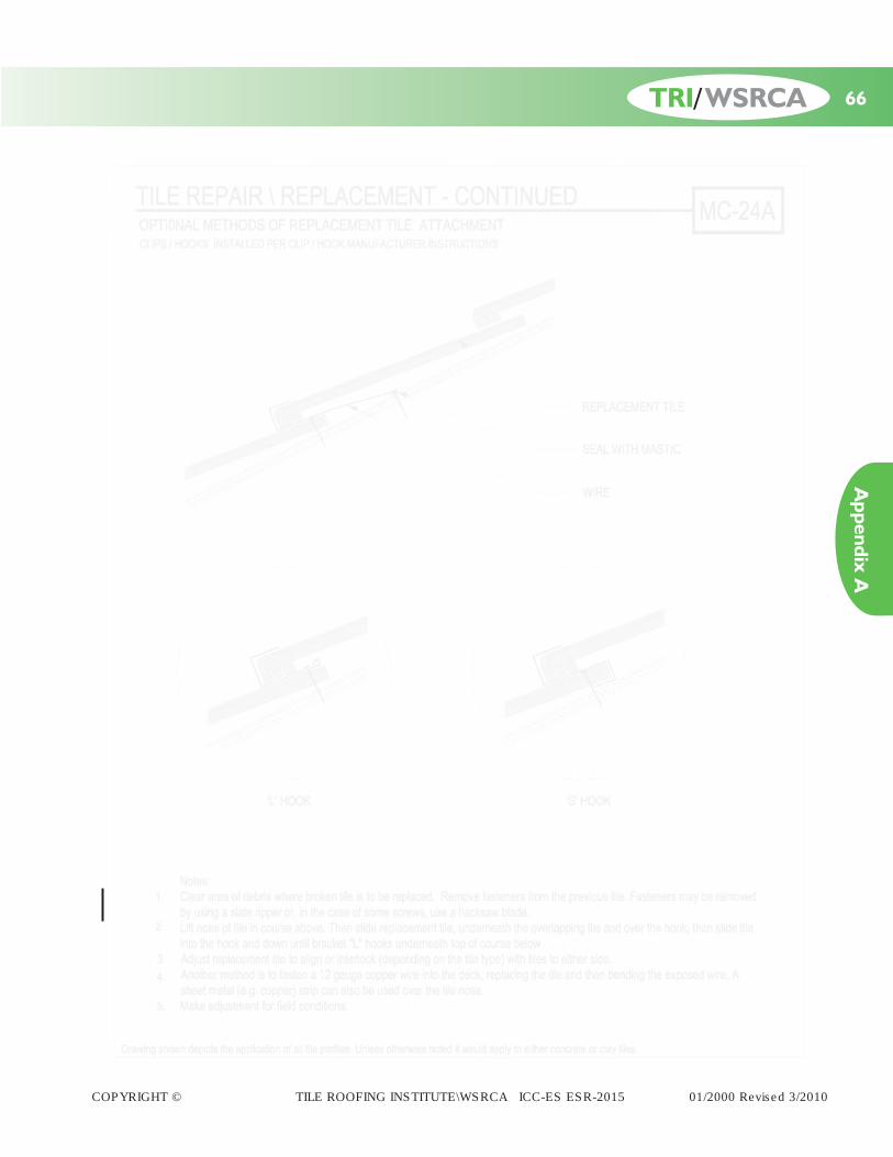
Broken Tile Replacement – The broken tile is firstremoved, if battens were used originally, existing fastenersif any, are cut, removed, underlayment repaired and thenew tile is inserted. If no battens were used, a 12" x 6" by½" plywood piece is nailed to the deck to act as a batten.As an alternative, new tiles may be inserted using roofersmastic, hooks, wires or approved adhesives to form thebond at the head of the lap area. See pages 65 and 66 (TileRepair).
Efflorescence – Efflorescence is a temporary surfacediscoloration common to all concrete based roofing tile.It is a nuisance not only to the manufacturer, but alsothose involved in specification, installation, and usage. Itis however, in no way detrimental to the overall quality,structural integrity, or functionality of the tile.
Efflorescence is mostly caused by the chemical nature ofthe cement. Manufactured cement contains free lime, andwhen water is added, a series of chemical reactions takeplace. These reactions are accompanied by the release ofcalcium hydroxide which can form a white chalky crys-talline salt deposit on the tile surface when reacting withcarbon dioxide. This reaction can appear as an overall“bloom” (overall softening of color) or in more concen-trated patches.
It is difficult to predict how long the effects of efflorescencewill last. It depends on the type and amount of deposit aswell as the local weather conditions. The action of carbondioxide and rain water will gradually, in most cases,remove the deposit leaving the original color of the con-crete roof tile intact without further efflorescence.
Walkability – The inert nature of tile, its characteristics ofstrength over age, and its durability will contribute to a longterm life expectancy. With a good installation and rea-sonable precautions against severe roof traffic, a tiledroof system will require very low maintenance. Walkingon a roofing tile should be done with extreme caution.Place antennas and roof mounted equipment where aminimum of roof traffic will be necessary for servicingand maintenance. If necessary to walk on the tile sur-faces, pressure should only be applied on the headlap ofthe tile units (lower 3-4 inches). This distributes the loadnear the bearing points of the tile. When painting orrepairing adjoining walls or appurtenances, safely coverthe tile surface with secured plywood to distribute trafficloads and prevent dirt, building materials, and paint/stainfrom damaging or discoloring the tile.
Weather Effects On Tile – After constant exposure tonature’s elements some tile can be expected to lighten tosome degree from the original color or lose some surfacetexture. This is due primarily to the effects of oxidationon the surface of the tile. This will not effect the struc-tural integrity or water shedding abilities of the tile.
Vermin Screening – Metal, honeycomb plastic, foamfillers, mortar or equivalent should be considered to seallarger access areas. This will help minimize the access ofbirds and vermin infiltration.
GENERAL INFORMATION
7
Installation
TRI/WSRCA
COPYRIGHT © TILE ROOFING INSTITUTE\WSRCA ICC-ES ESR-2015 01/2000 Revised 3/2010
Sheathing – Sheathing must be structurally adequate tosupport the loads involved and of a material recognizedin a code evaluation report or as approved by the localbuilding official.
Underlayment – One layer of minimum ASTM D226Type II (No. 30 felt) (ASTM D4869 Type IV) or approvedequal, with a recognized code evaluation report, shallcompletely cover the decking and be lapped over hips andridges and through valleys. Underlayment shall be lapped6" vertical (end or side lap) and 2" horizontally (head lap).
On roof slopes below 3:12 an approved multi-ply mem-brane roof such as a built-up roof system, applied inaccordance with Table 1A, or a single-ply roof membraneassembly, or other underlayment systems approved by
the local building official, is first installed. Tile installed at lessthan 3:12 shall be considered decorative.
Where roof slopes fall between 3:12 and under 4:12,underlayment shall be as described in the previous para-graph, underlayments meeting ASTM D1970 (such asEPDM, Ice and Water Shield), or two layers of ASTM D226Type II (No. 30 felt) (ASTM D4869 Type IV), installedshingle fashion, or single ply roof membrane assemblyinstalled per code, or other approved underlayments.
In locations where the January mean temperature is 25deg. F (-4 deg C) or less or where ice damming oftenoccurs, the TRI/WSRCA suggests reference to theConcrete and Clay Tile Roof Design Criteria Manual forCold and Snow Regions.
NEW CONSTRUCTIONSee Tables 1A, 1B and 3 for specific code related installation requirements.
Roof Layout – To achieve the optimum performanceand appearance, the roof area between the eave andridge should be divided into equal tile courses, when pos-sible. A minimum 3-inch overlap must be maintained forall tile, unless the tile design precludes. The actual layout
of the roof courses will be determined by the length ofthe specific tile being installed. Medium profiled tiles canbe installed either straight or staggered bond.
Please consult with the individual manufacturer for addi-tional information.
Batten Installation – Tiles with projecting anchor lugsthat are installed on battens below 3:12 slopes shall berequired to have one of the following batten systems orother methods as approved by the local building officials.
Nominal 1 inch by 2 inch, or greater, wood batten strips(See counter batten system.) installed over a counterbatten system are required where slopes fall below 3:12in order to minimize membrane penetration. Nominal 1inch by 2 inch, or greater, wood battens are requiredwhere slopes exceed 7:12, to provide positive tile anchoring.Battens are nailed to the deck with 8D corrosion resistantbox nails 24 inches on center, or No 16 gauge by 7/16inch-crown by 11/2 inch long corrosion-resistant stapleson 12-inch centers, allowing a 1/2" separation at thebatten ends. Tile installed on roof slopes of less than 3:12
are considered decorative only and must be applied oncounter battens over an approved membrane roof covering,subject to local building official approval.
Battens installed on roof slopes of 4:12 to 24:12 shall befastened to the deck at no greater than 24 inches on center,and shall have provisions for drainage by providing ½-inchseparation at the batten ends every 4 feet, or by shimmingwith a minimum 1/4" material of wood lath strips, 2-inchshims, cut from multiple layers of material, placedbetween the battens and deck to provide drainage beneaththe battens or other methods approved by the local build-ing official. Tile installed without projecting anchor lugsmay be installed as provided above as an optional methodof installation.
Counter Batten System – Counter battens 1/4” andlarger in height will be installed vertically on the roof toprovide the space between the battens, to which the tilesare attached, and the roof deck, thus facilitating air flowcapability and moisture drainage.
Taking the anticipated roof loading into account, design
consideration should be given to the size and quality ofthe wooden battens or sheathing boards used to supportthe roof tile covering.
If the battens are not strong enough to support the antici-pated loading, including the roof tile and snow and/or ice,the battens could deflect between the support points
8TRI/WSRCA
Installation

COPYRIGHT © TILE ROOFING INSTITUTE\WSRCA ICC-ES ESR-2015 01/2000 Revised 3/2010
causing roof tile breakage and/or other roof damage. Knotsand knot holes weaken the batten. See Table 2 on page 12.
Note: If a counter batten system is to be installed under theunderlayment, caution must be used to prevent damage to theunderlayment or a reinforced underlayment will be used.
REROOFINGRoof structure must be adequate to support the antici-pated roof load of tile.
Clay and concrete roofing tiles, recognized as a Class Aroof assembly passing testing according to ASTM E 108,UL 790 or recognized in accordance with IRC sectionR902.1, will be allowed to be installed over existingasphalt shingles, plywood or OSB.
Care will be taken to ensure both horizontal and verticalalignment on the roof.
Foreign matter will be cleaned from all interlocking areas.Cracked or broken tile must be removed from the roof.
Damaged, rusted, improper flashing will be replaced.
When reroofing wood shake/shingle roofs, existing
shakes/shingles shall be removed and solid sheathingdecking, tile, and flashings installed as with new construc-tion. One layer of ASTM D226 Type II (No. 30) (ASTMD4869 Type IV) felt or approved equal underlayment shallbe installed on the roof prior to application of tile. Wheninstalled over existing spaced sheathing boards, underlay-ment recognized by the local building code, for this typeof application with, or without battens, will be used.
In lieu of such underlayment’s being provided, the buildingofficial has the discretion to determine if the existing roofcovering provides the required underlayment protection.
Check with local building official for any additionalrequirements.
Follow installation requirements as listed for new con-struction, once these items listed have been addressed.
VENTILATION GUIDELINESThe need for proper attic ventilation is required by mostbuilding code authorities, in accordance with the IBC andIRC. These codes recognize that the proper ventilation isa necessary component of any successful steep slope roofsystem.
Generally building codes require that a minimum net free
ventilating area for attic vents be a 1:150 ratio of the atticspace being ventilated, the codes generally allow for thereduction of the ratio from 1:150 to 1:300 if the attic ventsare a balanced system on a roof and/or a vapor retarder isinstalled on a ceiling assembly’s warm side. Check withlocal building official for regional requirements.
9
Installation
TRI/WSRCA
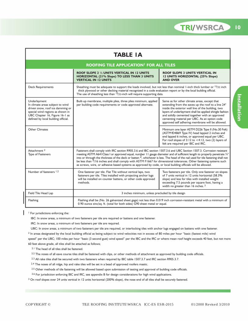
ROOFING TILE APPLICATION1 FOR ALL TILES
ROOF SLOPE 2 ½ UNITS VERTICAL IN 12 UNITS ROOF SLOPE 3 UNITS VERTICAL IN HORIZONTAL (21% Slope) TO LESS THAN 3 UNITS 12 UNITS HORIZONTAL (25% Slope) VERTICAL IN 12 UNITS AND OVER
Deck Requirements Sheathing must be adequate to support the loads involved, but not less than nominal 1-inch thick lumber or 15/32 inchthick plywood or other decking material recognized in a code evaluation report or by the local building official.The use of sheathing less than 15/32-inch will require supporting data.
Underlayment Built-up membrane, multiple plies, three plies minimum, applied Same as for other climate areas, except that In climate areas subject to wind per building code requirements or code approved alternate. extending from the eaves up the roof to a line 24"driven snow, roof ice damming or inside the exterior wall line of the building, twospecial wind regions as shown in layers of underlayment shall be applied shingle fashionUBC Chapter 16, Figure 16-1 as and solidly cemented together with an approveddefined by local building official. cementing material per UBC. As an option code
approved self adhering membrane will be allowed.
Other Climates Minimum one layer ASTM D226 Type II (No.30 Felt) (ASTM•D4869 Type IV) head lapped 2 inches and end lapped 6 inches, or approved equal per UBC.For roof slopes of 3:12 to <4:12, two (2) layers of felt are required per IBC and IRC.
Attachment 2 Fasteners shall comply with IRC section R905.3.6 and IBC section 1507.3.6 and UBC Section 1507.3. Corrosion resistantType of Fasteners meeting ASTM A641Class I or approved equal, number 11 gauge diameter and of sufficient length to properly penetrate ¾"
into or through the thickness of the deck or batten 2, whichever is less. The head of the nail used for tile fastening shall notbe less than 5/16 inches and shall comply with ASTM F1667 for dimensional tolerances. Other fastening systems such as screws, wire, or adhesive based systems as approved by code, or local building officials will be allowed.
Number of fasteners 1,2 One fastener per tile. Flat Tile without vertical laps, two Two fasteners per tile. Only one fastener on slopes fasteners per tile. Tiles installed with projecting anchor lugs of 7 units vertical in 12 units horizontal (58.3% will be installed on counter battens, or other code approved slope) and less for tiles with installed weight methods. exceeding 7.5 pounds per square foot, having a
width no greater than 16 inches. 3
Field Tile Head Lap 3 inches minimum, unless precluded by tile design
Flashing Flashing shall be (No. 26 galvanized sheet gage) not less than 0.019 inch corrosion-resistant metal with a minimum of 0.90 ounce zinc/sq. ft. (total for both sides) G90 sheet metal or equal.
1 For jurisdictions enforcing the:
IBC: In snow areas, a minimum of two fasteners per tile are required or battens and one fastener.
IRC: In snow areas, a minimum of two fasteners per tile are required.
UBC: In snow areas, a minimum of two fasteners per tile are required, or interlocking tiles with anchor lugs engaged on battens with one fastener.2 In areas designated by the local building official as being subject to wind velocities not in excess of 80 miles per hour “basic (fastest mile) wind
speed” per the UBC; 100 miles per hour “basic (3 second gust) wind speed” per the IBC and the IRC or where mean roof height exceeds 40 feet, but not more
60 feet above grade, all tiles shall be attached as follows;2.1 The head of all tiles shall be fastened.2.2 The noses of all eave course tiles shall be fastened with clips, or other methods of attachment as approved by building code officials.2.3 All rake tiles shall be secured with two fasteners when required by IBC table 1507.3.7 and IRC section R905.3.7.2.4 The noses of all ridge, hip and rake tiles will be set in a bead of approved roofers mastic.2.5 Other methods of tile fastening will be allowed based upon submission of testing and approval of building code officials.2.6 For jurisdiction enforcing IBC and IRC, see appendix B for design considerations for high wind applications.
3 On roof slopes over 24 units vertical in 12 units horizontal (200% slope), the nose end of all tiles shall be securely fastened.
TABLE 1A
COPYRIGHT © TILE ROOFING INSTITUTE\WSRCA ICC-ES ESR-2015 01/2000 Revised 3/2010
10
Installation
TRI/WSRCA

ROOFING TILE APPLICATION FOR INTERLOCKING CONCRETE AND CLAY TILES WITH PROJECTING ANCHOR LUGS WHEN INSTALLED ON ROOF SLOPES OF 4 UNITS
VERTICAL IN 12 UNITS HORIZONTAL (33% Slope) AND GREATER
4 UNITS VERTICAL IN 12 UNITS HORIZONTAL (33% Slope) and over
Deck Requirements Sheathing must be adequate to support the loads involved, but not less than nominal 1-inch thick lumber or 15/32- inchthick plywood or other decking material recognized in a code evaluation report or by the local building official. The useof sheathing less than 15/32- inch will require supporting data.
Underlayment Solid sheathing one layer of ASTM D226 Type II (No. 30) (ASTM•D4869 Type IV), or approved equal, lapped 2 inches In climate areas subject to wind horizontally and 6 inches vertically, except that extending from the eaves up the roof to a line 24 inches inside the driven snow, roof ice damming exterior wall line of the building, two layers of the underlayment shall be applied shingle fashion and solidly cemented or wind regions as defined by together with approved cemented material. As an option a code approved self adhering membrane may be used. local building codes
Underlayment for For spaced sheathing, approved reinforced membrane. For solid sheathing, a minimum single layer ASTM D226 Other Climates Type II (No 30) (ASTM D4869 Type IV), or approved equal, felt lapped 2 inches horizontally and 6 inches vertically.
Attachment1 Fasteners shall comply with IRC section R905.3.6 and IBC section 1507.3.6 and UBC Section 1507.3 and shall comply withType of Fasteners ASTM F1667 for tolerances. Corrosion resistant meeting ASTM A641 Class 1 or approved equal, or number 11 gauge
diameter and of sufficient length to properly penetrate ¾" into or through the thickness of the deck or batten 3, whichever isless. The head of the nail used for tile fastening will not be less than 5/16 inches and shall comply with ASTM F1667 fortolerances. Other fastening systems such as screws, wire or adhesive based systems as approved by code, or local buildingofficials will be allowed. Horizontal battens are required on solid sheathing for slopes greater than 7 units vertical in 12 unitshorizontal (58.3% Slope).1, 2
Number of fasteners 5 units vertical in 12 units horizontal and below (42% slope), fasteners not required. Above 5 units vertical in 12 units Spaced/Solid sheathing horizontal (42% slope) to less than 12 units vertical in 12 units horizontal (100% slope), one fastener per tile every With Battens or spaced sheathing 1, 2 other row or every other tile in each course. Twelve units vertical in 12 units horizontal (100% Slope) to 24 units vertical
in 12 units horizontal (200% slope), one fastener every tile4. All perimeter tiles require one fastener5. Tiles with installedweight less than 9 pounds per square foot require a minimum of one fastener per tile, regardless of roof slope. See current codeapproved evaluation report for additional installation requirement.
Solid sheathing without battens 1, 2 One fastener per tile
Field Tile Head Lap 3 inches minimum unless precluded by tile design
Flashing Flashing shall be (No. 26 galvanized sheet gage) not less than 0.019 inch corrosion-resistant metal with a minimum of 0.90 ounce zinc/sq. ft. (total for both sides) G90 sheet metal or equal.
1 For jurisdictions enforcing the:IBC: In snow areas, a minimum of two fasteners per tile are required or battens and one fastener.IRC: In snow areas, a minimum of two fasteners per tile are required.UBC: In snow areas, a minimum of two fasteners per tile are required, or interlocking tiles with anchor lugs engaged on battens with one fastener.
2 In areas designated by the local building official as being subject to wind velocities not in excess of 80 miles per hour “basic (fastest mile) wind speed”per the UBC; 100 mile per hour “basic (3 second gust) wind speed” per the IBC and the IRC or where mean roof height exceeds 40 feet, but not morethan 60 feet above grade, all tiles shall be attached as follows:2.1 The heads of all tiles shall be fastened.2.2 The noses of all eave course tiles shall be fastened with clips, or other methods of attachment as approved by building code officials.2.3 All rake tiles shall be secured with two fasteners when required by IBC table 1507.3.7, IRC section R905.3.7 or UBC Table 15-D-2 as applicable.2.4 The noses of all ridge, hip and rake tiles shall be set in a bead of approved roofers mastic.2.5 Other methods of tile fastening will be allowed based upon submission of testing and approval of building code officials.2.6 For jurisdictions enforcing the IBC and the IRC, see appendix B for design considerations for high wind applications.
3 Battens shall not be less than nominal 1-inch by 2-inch complying with IBC Chapter 23, section 2302. Provisions shall be made for drainage beneath battens by a minimum ¼-inch riser at each nail or by 4 foot long battens with at least ½-inch separation between battens or other methods approved by local buildingofficials. For jurisdictions enforcing the UBC, battens shall be fastened with approved fasteners spaced not more than 24" O.C. For jurisdictions enforcing the IBC horizontal battens are required for slopes over 7:12.
4 On roof slopes over 24 units vertical in 12 units horizontal (200% slope), the nose end of all tiles shall be securely fastened.5 Perimeter fastening areas include three tile courses but not less than 36 inches from either side of hips or ridges and edges of eaves and gable rakes.
TABLE 1B (Alternative option) For Roof Slopes Below 4:12 See Table 1A
COPYRIGHT © TILE ROOFING INSTITUTE\WSRCA ICC-ES ESR-2015 01/2000 Revised 3/2010
11 TRI/WSRCA
Installation

12TRI/WSRCA
Installation
COPYRIGHT © TILE ROOFING INSTITUTE\WSRCA ICC-ES ESR-2015 01/2000 Revised 3/2010

COPYRIGHT © TILE ROOFING INSTITUTE\WSRCA ICC-ES ESR-2015 01/2000 Revised 3/2010
TABLE 3GUIDELINES FOR BATTENS & COUNTER BATTENS
ROOF SLOPE STANDARD REQUIREMENTS OPTIONAL UPGRADE(S)
2 1/2 / 12 (21%) TO LESS Counter Batten System Alternates:THAN 3/12 (25%) Refer to Counter Batten Systems (Page 6) & MC-05 / Corrosive resistant metal, or other man-
MC-06A made material that meets the allowable loads (see Table 2), ICC-ES recognized, and/or approval of the local building official.
3/12 (25%) TO Not Required Nominal* 1" x 2" x 4' or less7/12 (58.3%) See below for special climatic conditions (min 1/2" separation between battens)
Nominal* 1" x 2" x greater than 4'(Provision for drainage beneath batten with min 1/4" thick decay-resistant riser at each fastener)
Counter BattenRefer to Counter Batten Systems (Page 6)& MC-05 / MC-06A
Alternates:Corrosive resistant metal, or other man-made material that meets the approval of the local building official and/or ICC-ESrecognized batten system.
GREATER THAN Nominal* 1" x 2" x 4' Counter Batten7/12 (58.3%) (min 1/2" separation between battens) Refer to Counter Batten Systems (Page 6)
& MC-05 / MC-06A
Nominal* 1" x 2" x 8' Alternates:(Provision for drainage beneath batten with min 1/4" thick Corrosive resistant metal, or other man-decay-resistant riser at each fastener) made material that meets the approval of
the local building official and/or ICC-ESrecognized batten system.
Nominal:* Refer to IBC, Chapter 23 (WOOD), SECTION 2302 (DEFINITIONS).
Allowable Loads: When using counter battens, refer to Table 2 for additional load considerations.
Batten Fastening: 24" OC to the deck with 8d corrosive resistant nails.12" OC to the deck with No 16 gauge by 7/16-inch crown by 1 1/2-inch long corrosive-resistant staples.Once the batten is installed, it becomespart of the deck for fastening purposes.
Climatic Conditions: In dry/low humidity climates, moisture resistant battens are not required.Consideration should be given to lower slope roofs that are susceptible to wind driven snow and rain. Optional upgrades should be considered.Standard 4' battens fastened direct tothe deck are not allowed in the Cool/ Humid climate zone. Batten systems that provide drainage/air-flow (shims, counter battens or other approved systems) are required.
Hot/humid climate
Cool/humid climate
Mixed and cold climate
Hot/ dry and cool/dry climates
13 TRI/WSRCA
Installation
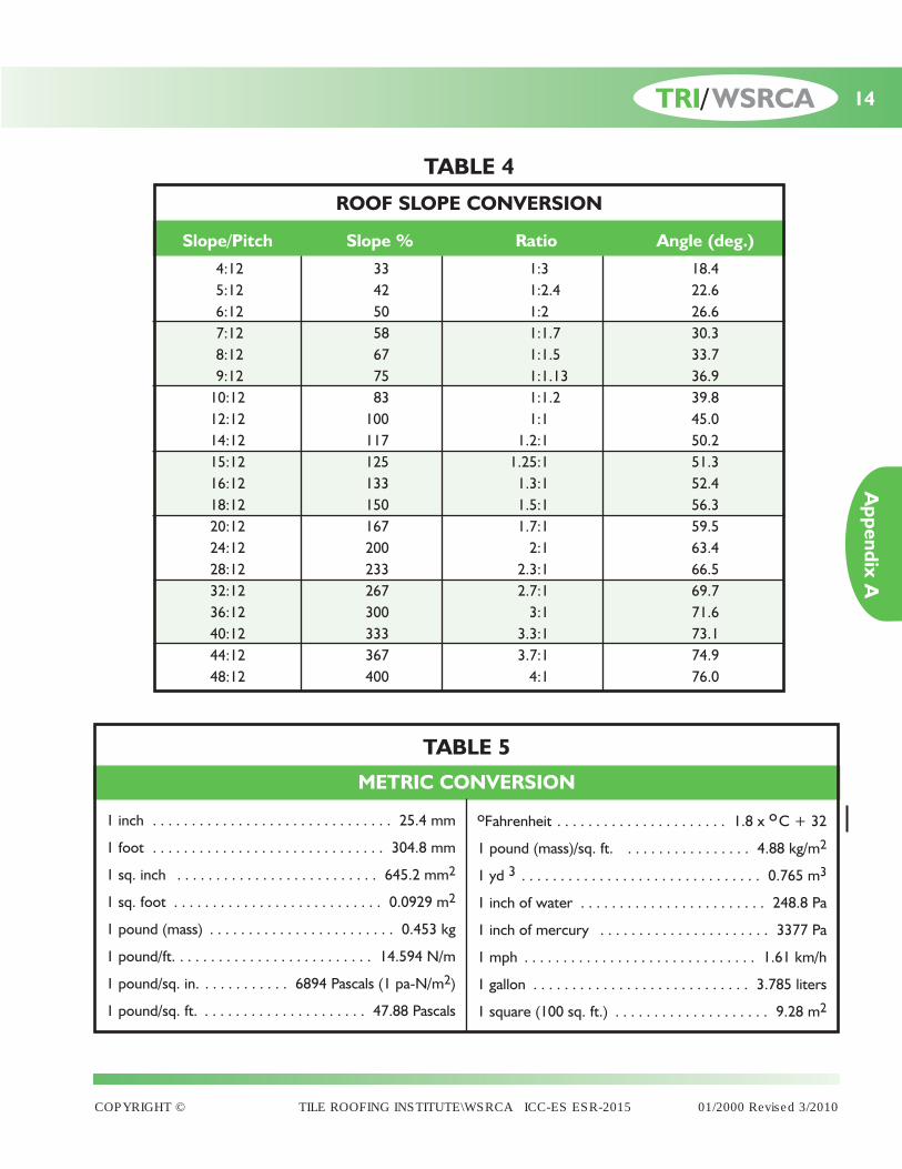
Slope/Pitch Slope % Ratio Angle (deg.)
4:12 33 1:3 18.45:12 42 1:2.4 22.66:12 50 1:2 26.67:12 58 1:1.7 30.38:12 67 1:1.5 33.79:12 75 1:1.13 36.910:12 83 1:1.2 39.812:12 100 1:1 45.014:12 117 1.2:1 50.215:12 125 1.25:1 51.316:12 133 1.3:1 52.418:12 150 1.5:1 56.320:12 167 1.7:1 59.524:12 200 2:1 63.428:12 233 2.3:1 66.532:12 267 2.7:1 69.736:12 300 3:1 71.640:12 333 3.3:1 73.144:12 367 3.7:1 74.948:12 400 4:1 76.0
TABLE 4
ROOF SLOPE CONVERSION
1 inch . . . . . . . . . . . . . . . . . . . . . . . . . . . . . . . 25.4 mm
1 foot . . . . . . . . . . . . . . . . . . . . . . . . . . . . . . 304.8 mm
1 sq. inch . . . . . . . . . . . . . . . . . . . . . . . . . . 645.2 mm2
1 sq. foot . . . . . . . . . . . . . . . . . . . . . . . . . . . 0.0929 m2
1 pound (mass) . . . . . . . . . . . . . . . . . . . . . . . . 0.453 kg
1 pound/ft. . . . . . . . . . . . . . . . . . . . . . . . . . 14.594 N/m
1 pound/sq. in. . . . . . . . . . . . 6894 Pascals (1 pa-N/m2)
1 pound/sq. ft. . . . . . . . . . . . . . . . . . . . . . 47.88 Pascals
TABLE 5
METRIC CONVERSION
oFahrenheit . . . . . . . . . . . . . . . . . . . . . . 1.8 x oC + 32
1 pound (mass)/sq. ft. . . . . . . . . . . . . . . . . 4.88 kg/m2
1 yd 3 . . . . . . . . . . . . . . . . . . . . . . . . . . . . . . . 0.765 m3
1 inch of water . . . . . . . . . . . . . . . . . . . . . . . . 248.8 Pa
1 inch of mercury . . . . . . . . . . . . . . . . . . . . . . 3377 Pa
1 mph . . . . . . . . . . . . . . . . . . . . . . . . . . . . . . 1.61 km/h
1 gallon . . . . . . . . . . . . . . . . . . . . . . . . . . . . 3.785 liters
1 square (100 sq. ft.) . . . . . . . . . . . . . . . . . . . . 9.28 m2
COPYRIGHT © TILE ROOFING INSTITUTE\WSRCA ICC-ES ESR-2015 01/2000 Revised 3/2010
14TRI/WSRCA
Appendix A

15 TRI/WSRCA
Appendix A
COPYRIGHT © TILE ROOFING INSTITUTE\WSRCA ICC-ES ESR-2015 01/2000 Revised 3/2010

16TRI/WSRCA
Appendix A
COPYRIGHT © TILE ROOFING INSTITUTE\WSRCA ICC-ES ESR-2015 01/2000 Revised 3/2010

17 TRI/WSRCA
Appendix A
COPYRIGHT © TILE ROOFING INSTITUTE\WSRCA ICC-ES ESR-2015 01/2000 Revised 3/2010
18TRI/WSRCA
Appendix A
COPYRIGHT © TILE ROOFING INSTITUTE\WSRCA ICC-ES ESR-2015 01/2000 Revised 3/2010

19 TRI/WSRCA
Appendix A
COPYRIGHT © TILE ROOFING INSTITUTE\WSRCA ICC-ES ESR-2015 01/2000 Revised 3/2010

20TRI/WSRCA
Appendix A
COPYRIGHT © TILE ROOFING INSTITUTE\WSRCA ICC-ES ESR-2015 01/2000 Revised 3/2010

21 TRI/WSRCA
Appendix A
COPYRIGHT © TILE ROOFING INSTITUTE\WSRCA ICC-ES ESR-2015 01/2000 Revised 3/2010

22TRI/WSRCA
Appendix A
COPYRIGHT © TILE ROOFING INSTITUTE\WSRCA ICC-ES ESR-2015 01/2000 Revised 3/2010

23 TRI/WSRCA
Appendix A
COPYRIGHT © TILE ROOFING INSTITUTE\WSRCA ICC-ES ESR-2015 01/2000 Revised 3/2010

24TRI/WSRCA
Appendix A
COPYRIGHT © TILE ROOFING INSTITUTE\WSRCA ICC-ES ESR-2015 01/2000 Revised 3/2010
25 TRI/WSRCA
Appendix A
COPYRIGHT © TILE ROOFING INSTITUTE\WSRCA ICC-ES ESR-2015 01/2000 Revised 3/2010

26TRI/WSRCA
Appendix A
COPYRIGHT © TILE ROOFING INSTITUTE\WSRCA ICC-ES ESR-2015 01/2000 Revised 3/2010

27 TRI/WSRCA
Appendix A
COPYRIGHT © TILE ROOFING INSTITUTE\WSRCA ICC-ES ESR-2015 01/2000 Revised 3/2010
28TRI/WSRCA
Appendix A
COPYRIGHT © TILE ROOFING INSTITUTE\WSRCA ICC-ES ESR-2015 01/2000 Revised 3/2010

29 TRI/WSRCA
Appendix A
COPYRIGHT © TILE ROOFING INSTITUTE\WSRCA ICC-ES ESR-2015 01/2000 Revised 3/2010

30TRI/WSRCA
Appendix A
COPYRIGHT © TILE ROOFING INSTITUTE\WSRCA ICC-ES ESR-2015 01/2000 Revised 3/2010

31 TRI/WSRCA
Appendix A
COPYRIGHT © TILE ROOFING INSTITUTE\WSRCA ICC-ES ESR-2015 01/2000 Revised 3/2010

32TRI/WSRCA
Appendix A
COPYRIGHT © TILE ROOFING INSTITUTE\WSRCA ICC-ES ESR-2015 01/2000 Revised 3/2010

33 TRI/WSRCA
Appendix A
COPYRIGHT © TILE ROOFING INSTITUTE\WSRCA ICC-ES ESR-2015 01/2000 Revised 3/2010

34
Appendix A
TRI/WSRCA
COPYRIGHT © TILE ROOFING INSTITUTE\WSRCA ICC-ES ESR-2015 01/2000 Revised 3/2010

35 TRI/WSRCA
Appendix A
COPYRIGHT © TILE ROOFING INSTITUTE\WSRCA ICC-ES ESR-2015 01/2000 Revised 3/2010

36TRI/WSRCA
Appendix A
COPYRIGHT © TILE ROOFING INSTITUTE\WSRCA ICC-ES ESR-2015 01/2000 Revised 3/2010

37 TRI/WSRCA
Appendix A
COPYRIGHT © TILE ROOFING INSTITUTE\WSRCA ICC-ES ESR-2015 01/2000 Revised 3/2010

38TRI/WSRCA
Appendix A
COPYRIGHT © TILE ROOFING INSTITUTE\WSRCA ICC-ES ESR-2015 01/2000 Revised 3/2010

39 TRI/WSRCA
Appendix A
COPYRIGHT © TILE ROOFING INSTITUTE\WSRCA ICC-ES ESR-2015 01/2000 Revised 3/2010
40TRI/WSRCA
Appendix A
COPYRIGHT © TILE ROOFING INSTITUTE\WSRCA ICC-ES ESR-2015 01/2000 Revised 3/2010
41 TRI/WSRCA
Appendix A
COPYRIGHT © TILE ROOFING INSTITUTE\WSRCA ICC-ES ESR-2015 01/2000 Revised 3/2010

42TRI/WSRCA
Appendix A
COPYRIGHT © TILE ROOFING INSTITUTE\WSRCA ICC-ES ESR-2015 01/2000 Revised 3/2010

43 TRI/WSRCA
Appendix A
COPYRIGHT © TILE ROOFING INSTITUTE\WSRCA ICC-ES ESR-2015 01/2000 Revised 3/2010

44TRI/WSRCA
Appendix A
COPYRIGHT © TILE ROOFING INSTITUTE\WSRCA ICC-ES ESR-2015 01/2000 Revised 3/2010

45 TRI/WSRCA
Appendix A
COPYRIGHT © TILE ROOFING INSTITUTE\WSRCA ICC-ES ESR-2015 01/2000 Revised 3/2010

46TRI/WSRCA
Appendix A
COPYRIGHT © TILE ROOFING INSTITUTE\WSRCA ICC-ES ESR-2015 01/2000 Revised 3/2010

47 TRI/WSRCA
Appendix A
COPYRIGHT © TILE ROOFING INSTITUTE\WSRCA ICC-ES ESR-2015 01/2000 Revised 3/2010

48TRI/WSRCA
Appendix A
COPYRIGHT © TILE ROOFING INSTITUTE\WSRCA ICC-ES ESR-2015 01/2000 Revised 3/2010

49 TRI/WSRCA
Appendix A
COPYRIGHT © TILE ROOFING INSTITUTE\WSRCA ICC-ES ESR-2015 01/2000 Revised 3/2010

50TRI/WSRCA
Appendix A
COPYRIGHT © TILE ROOFING INSTITUTE\WSRCA ICC-ES ESR-2015 01/2000 Revised 3/2010

51 TRI/WSRCA
Appendix A
COPYRIGHT © TILE ROOFING INSTITUTE\WSRCA ICC-ES ESR-2015 01/2000 Revised 3/2010

52TRI/WSRCA
Appendix A
COPYRIGHT © TILE ROOFING INSTITUTE\WSRCA ICC-ES ESR-2015 01/2000 Revised 3/2010
53 TRI/WSRCA
Appendix A
COPYRIGHT © TILE ROOFING INSTITUTE\WSRCA ICC-ES ESR-2015 01/2000 Revised 3/2010

54TRI/WSRCA
Appendix A
COPYRIGHT © TILE ROOFING INSTITUTE\WSRCA ICC-ES ESR-2015 01/2000 Revised 3/2010

55 TRI/WSRCA
Appendix A
COPYRIGHT © TILE ROOFING INSTITUTE\WSRCA ICC-ES ESR-2015 01/2000 Revised 3/2010

56TRI/WSRCA
Appendix A
COPYRIGHT © TILE ROOFING INSTITUTE\WSRCA ICC-ES ESR-2015 01/2000 Revised 3/2010

57 TRI/WSRCA
Appendix A
COPYRIGHT © TILE ROOFING INSTITUTE\WSRCA ICC-ES ESR-2015 01/2000 Revised 3/2010
58TRI/WSRCA
Appendix A
COPYRIGHT © TILE ROOFING INSTITUTE\WSRCA ICC-ES ESR-2015 01/2000 Revised 3/2010

59 TRI/WSRCA
Appendix A
COPYRIGHT © TILE ROOFING INSTITUTE\WSRCA ICC-ES ESR-2015 01/2000 Revised 3/2010

60TRI/WSRCA
Appendix A
COPYRIGHT © TILE ROOFING INSTITUTE\WSRCA ICC-ES ESR-2015 01/2000 Revised 3/2010

61 TRI/WSRCA
Appendix A
COPYRIGHT © TILE ROOFING INSTITUTE\WSRCA ICC-ES ESR-2015 01/2000 Revised 3/2010
62TRI/WSRCA
Appendix A
COPYRIGHT © TILE ROOFING INSTITUTE\WSRCA ICC-ES ESR-2015 01/2000 Revised 3/2010

63 TRI/WSRCA
Appendix A
COPYRIGHT © TILE ROOFING INSTITUTE\WSRCA ICC-ES ESR-2015 01/2000 Revised 3/2010

64TRI/WSRCA
Appendix A
COPYRIGHT © TILE ROOFING INSTITUTE\WSRCA ICC-ES ESR-2015 01/2000 Revised 3/2010

65 TRI/WSRCA
Appendix A
COPYRIGHT © TILE ROOFING INSTITUTE\WSRCA ICC-ES ESR-2015 01/2000 Revised 3/2010
66TRI/WSRCA
Appendix A
COPYRIGHT © TILE ROOFING INSTITUTE\WSRCA ICC-ES ESR-2015 01/2000 Revised 3/2010

67 TRI/WSRCA
Appendix A
SPECIALTY INSTALLATIONSFor Informational Purposes Only–These have not been evaluated by ICC-ES Reports.
COPYRIGHT © TILE ROOFING INSTITUTE\WSRCA ICC-ES ESR-2015 01/2000 Revised 3/2010

68TRI/WSRCA
Appendix A
SPECIALTY INSTALLATIONSFor Informational Purposes Only–These have not been evaluated by ICC-ES Reports.
COPYRIGHT © TILE ROOFING INSTITUTE\WSRCA ICC-ES ESR-2015 01/2000 Revised 3/2010
69 TRI/WSRCA
Appendix A
SPECIALTY INSTALLATIONSFor Informational Purposes Only–These have not been evaluated by ICC-ES Reports.
COPYRIGHT © TILE ROOFING INSTITUTE\WSRCA ICC-ES ESR-2015 01/2000 Revised 3/2010

70TRI/WSRCA
Appendix A
SPECIALTY INSTALLATIONSFor Informational Purposes Only–These have not been evaluated by ICC-ES Reports.
COPYRIGHT © TILE ROOFING INSTITUTE\WSRCA ICC-ES ESR-2015 01/2000 Revised 3/2010

71 TRI/WSRCA
Appendix A
SPECIALTY INSTALLATIONSFor Informational Purposes Only–These have not been evaluated by ICC-ES Reports.
COPYRIGHT © TILE ROOFING INSTITUTE\WSRCA ICC-ES ESR-2015 01/2000 Revised 3/2010

72 TRI/WSRCA
Appendix A
SPECIALTY INSTALLATIONSFor Informational Purposes Only–These have not been evaluated by ICC-ES Reports.
COPYRIGHT © TILE ROOFING INSTITUTE\WSRCA ICC-ES ESR-2015 01/2000 Revised 3/2010

73 TRI/WSRCA
Appendix A
SPECIALTY INSTALLATIONSFor Informational Purposes Only–These have not been evaluated by ICC-ES Reports.
COPYRIGHT © TILE ROOFING INSTITUTE\WSRCA ICC-ES ESR-2015 01/2000 Revised 3/2010
74 TRI/WSRCA
Appendix A
SPECIALTY INSTALLATIONSFor Informational Purposes Only–These have not been evaluated by ICC-ES Reports.
COPYRIGHT © TILE ROOFING INSTITUTE\WSRCA ICC-ES ESR-2015 01/2000 Revised 3/2010

75 TRI/WSRCA
Appendix A
SPECIALTY INSTALLATIONS
COPYRIGHT © TILE ROOFING INSTITUTE\WSRCA ICC-ES ESR-2015 01/2000 Revised 3/2010
Underlayment applications under battens (e.g.,sarking systems or open batten systems) that isrecognized in an ICC-ES Evaluation Report for thisuse and approved by local building officials.
DRAPED•UNDERLAYMENT APPLICATIONS
INSTALLATION OF UNDERLAYMENT UNDER SPACED SHEATHING (Draped Underlayment)
ROLLED UNDERLAYMENT
A tapered antiponding board not less than 8" x 1/2" shall benailed to the top of the fascia board to prevent the under-layment from sagging below the line of the fascia board.
The underlayment shall drape not less than 3/4" and nomore than 1 1/2" between the trusses or rafters.
The underlayment shall be laid over the ridge to provide6" laps in each direction at ridges (providing a minimum12" overlap).
The underlayment shall be laid over the hip to provideminimum 6" side laps in each direction at hips and shall befastened at two adjacent trusses or rafters.
When ending a roll in the field or the truss or rafter, begin anew roll one full truss or rafter back creating 24" side lapand mechanically fix both end and starter rolls on a member.
At roof-to-wall and roof-to-curb intersections/abutmentsthe underlayment shall be turned up not less than 6" andshall be fastened to the abutting wall.
A lining ply or sheet of underlayment shall be installed inthe valley and extend not less than 24" on each side of thevalley center line. Underlayment shall be laid from eachadjacent roof side parallel with the fascia board, ordownslope roof perimeter, and shall be brought to thevalley centerline.
Vents and protrusions such as plumbing stacks shall beflashed or sealed at the underlayment layer with mem-brane compatible sealant to prevent water from passinginto the attic space.
RIGID UNDERLAYMENT
Rigid underlayment shall be installed with the longest sidehorizontal, allowing a minimum 6" side lap on the trussesor rafters and a minimum 4" head lap.
At the eave the underlayment shall overhang not less than3/4" and shall be protected by an approved self adheringmembrane a minimum of 6" on both sides.
Where a fascia board is used, the underlayment shall befastened to the top of the fascia board and the junction ofthe trusses or rafters at the fascia.
The underlayment shall lap ridges and hips a minimum 6" ineach direction, providing a total 12" overlap. At hip loca-tions fastened to an adjacent truss or rafter.
A lining ply or base sheet shall be installed in the valleyand extend not less than 24" on each side of the valleycenter line. The head lap shall be a minimum of 4".
Vents and protrusions, such as plumbing stacks, shall beflashed or sealed at the underlayment layer with mem-brane compatible sealant to prevent water from passinginto the attic space.
TILE BATTENS FOR SPACED SHEATHING
Tile battens for spaced sheathing shall be a minimum 1" x 4"nominal spruce/pine/fir (SPF) standard No. 2 or bettergrade, or structurally equal. Fasteners and other fasteningdevices shall be corrosion resistant with shanks a mini-mum No. 11 gauge diameter and of sufficient length topenetrate 3/4" into the truss or rafter.
Two types of underlayment may be used in drapedapplications:
Rolled underlayment (non-rigid) Rigid underlayment (rigid board)
COPYRIGHT © TILE ROOFING INSTITUTE\WSRCA ICC-ES ESR-2015 01/2000 Revised 3/2010
76 TRI/WSRCA
Appendix B

COPYRIGHT © TILE ROOFING INSTITUTE\WSRCA ICC-ES ESR-2015 01/2000 Revised 3/2010
As an alternative to mechanical fastening of roof tiles, theuse of foam adhesive securement systems that areapproved by the authority having jurisdiction may beused.
The restrictions, if any, are found in the code approval orevaluation report and will address any special considerationsfor underlayment attachment climate restrictions and therequired amount and placement of the foam adhesivematerials to provide the code required uplift resistance
when installed on direct deck and batten applicationsfor concrete and clay tile.
When deciding to use foam adhesives for the securementof tile, consideration must be made on the compatibilityof the adhesive to the underlayment surface. Althoughmost code approved foam adhesives bond well to a varietyof products like smooth or granulated underlayments,metal, concrete, clay, wood, etc., typically, they do notadhere to polyethylene or silicon surfaced products.
ADHESIVE SECUREMENT SYSTEMS(WHEN USED AS AN ALTERNATIVE TO MECHANICAL FASTENING)
77
Appendix B
TRI/WSRCA
The installation requirements provided in Table 1A and 1Bprovide the normal installation guidelines for concrete andclay tile to comply with the International Building Code(Section 1507.3.7). The installation of tile in the specificregions of the country that are identified by ASCE 7-05 assubjected to wind speeds in excess of 100 miles per hour,may be required to have additional fastening options notfound in Tables 1A and 1B.
The Tile Roofing Institute has derived various uplift resist-ance values for nails, screws and adhesive fastening systems.Each of these methods of installation may have limitingfactors depending upon wind speed, roof slope and roofheight. Please consult with your tile supplier or design pro-fessional for additional information about these optionalsystems for those unique installations.
Design Considerations For High Wind ApplicationsPlease Refer to Tile Manufacturer’s ICC-ES Evaluation Report for Additional Details.
IRC: On buildings having a maximum mean roof height of40 feet (12.2m), tile application must comply with IRCsection R905.3.7. For higher basic wind speeds or meanroof heights, installation must be in compliance with IBCSections 1507.3.7 & 1609.5.3.
The following design aids are provided to the roof designerfor consideration in determining the required aerodynamicuplift moment for roof tiles for wind applications beyondthe prescriptive requirements in the IBC or IRC. Thesetables were developed based on the requirements of IBCSection 1609.5.3 and ASCE 7-05. Buildings and otherstructures that represent a substantial hazard to human lifein the event of failure are to be designed using anImportance Factor of 1.15 (See ASCE 7-05, Table 1-1 formore information).
Design of Attachment System:
Building is a low rise structure located in an Exposure B region where thebasic wind speed is 140 mph (3-second gust). The building is a Category IIstructure. The mean roof height of the building is 30 feet. The roof is agable roof with a roof slope of 3:12. The terrain around the buildingdoes not abruptly change so as to create any wind speedup effects dueto channeling, or shielding. The building is not located on a hill, ridge,or escarpment that would cause the wind to speedup. The roof tileswill be flat/low profile concrete roof tile with a total tile length of 16-½"and an exposed width of 11". The roof tiles weigh 9 pounds each. Theroof covering is installed on solid sheathing.
Example 1: Calculate the Required Aerodynamic Uplift Momentand the Allowable Aerodynamic Uplift Resistance from Table 7:
Velocity Pressure:
qh = 0.00256 Kz Kzt Kd V2 I (ASCE 7 - 6.5.10)
qh = velocity pressure elevation at height z (psf)
Kz = velocity pressure exposure coefficient at height z(ASCE 7 - Table 6-3)
Kz = 0.70
Kzt = topographic factor (ASCE 7 - Figure 6-4)
Kzt = 1.00cont’d on page 78

COPYRIGHT © TILE ROOFING INSTITUTE\WSRCA ICC-ES ESR-2015 01/2000 Revised 3/2010
cont’d on page 79
78
Appendix B
TRI/WSRCA
Kd = wind directionality factor (ASCE 7 - Table 6-4)
Kd = 0.85
V = basic wind speed (mph) (ASCE 7 - Figure 6-1)
V = 140 mph
I = importance factor (ASCE 7 - Table 6-1)
I = 1.00
qh = 0.00256 Kz Kzt Kd V2 I = 0.00256 (0.70) (1.00) (0.85) (140 mph)2 (1.00)
qh = 29.85 psf
Required Aerodynamic Uplift Moment:
Ma = qh CL b L La (1- GCp) (IBC - Eq. 16-33)
Ma = aerodynamic uplift moment (ft-lbf)
qh = velocity pressure elevation at mean roof height h (psf)
qh = 29.85 psf
CL = lift coefficient = 0.2 (IBC - Section 1609.5.3)
b = exposed width of roof tile (ft)
b = 11" ~ 0.917'
L = length of roof tile (ft)
L = 16-½" ~ 1.375'
La =moment arm for the roof tile = 0.76 L(IBC - Section 1609.7.3)
La = 0.76 (16-½") = 12.54" ~ 1.045'
GCp = product of external pressure coefficient and gust factor
GCp = -2.6
Note: The external pressure coefficient for Zone 3 was selected tocalculate the required aerodynamic uplift moment. The use of thisexternal pressure coefficient is conservative for zones 1 and 2.
Ma = qh CL b L La (1- GCp) = (29.85 psf) (0.2) (0.917')(1.375') (1.045') (1 - [-2.6])
Ma = 28.3 ft lbf
Required Aerodynamic Uplift Resistance:
For a direct deck installation select a fastening system from Table 7,Allowable Aerodynamic Uplift Moments - Mechanical FasteningSystems that is equal to or greater than 28.3 ft-lbf in order to complywith the code, such as 2-10d ring shank nails or 1-#8 screw.
2-10d ring shank nails = 39.1 ft-lbf (TRI Manual - Table 7)
1-#8 screw = 39.1 ft-lbf (TRI Manual - Table 7)
Example 2: Determine the Required Aerodynamic Uplift Momentusing Table 5 or Table 6 and Allowable Aerodynamic UpliftResistance from Table 7:
The flat/low concrete roof tile is within the combined maximum tilelength and maximum exposed width listed in Table 6E, MaximumCombination of Tile Length and Tile's Exposed Width. This roof tilemay be designed using the appropriate Table 5 or Table 6.
Based on the exposure and the roof pitch the appropriate table isTable 5A, Exposure B - Required Aerodynamic Uplift Moment. Table5A indicates that the required aerodynamic uplift moment for thisroof covering, Ma, is 30.3 ft-lbf.
Required aerodynamic uplift moment, Ma, = 30.3 ft lbf
(TRI Manual - Table 5A)
Note: The difference between the Ma's in Example 1 and Example 2is in the tile factor. Table 5 and Table 6 are based on a tile factor of1.407 ft³ while the actual tile factor for this roof tile is 1.318 ft³. (TileFactor = b L La = (0.917') (1.375') (1.045') = 1.318 ft³).
Required Aerodynamic Uplift Resistance:
For a direct deck installation select a fastening system from Table 7,Allowable Aerodynamic Uplift Moments - Mechanical FasteningSystems that is equal to or greater than 30.3 ft-lbf in order to complywith the code, such as 2-10d ring shank nails or 1-#8 screw.
2-10d ring shank nails = 39.1 ft-lbf (TRI Manual - Table 7)
1-#8 screw = 39.1 ft-lbf (TRI Manual - Table 7)
Example 3: Design the Roof Tile Installation for a LightweightRoof Tile:
The roof tile installation is identical to the previous examples exceptthat the roof tiles lightweight roof tiles weighing 5 pounds each.
The flat/low lightweight concrete roof tile is within the combinedmaximum tile length and maximum exposed width listed in Table 6E,Maximum Combination of Tile Length and Tile's Exposed Width. Thisroof tile may be designed using the appropriate Table 5 or Table 6.
Required Aerodynamic Uplift Moment:Based on the exposure and the roof pitch the appropriate table isTable 5A, Exposure B - Required Aerodynamic Uplift Moment. Table5A indicates that the required aerodynamic uplift moment for thisroof covering, Ma, is 30.3 ft-lbf.
Ma, = 30.3 ft lbf (TRI Manual - Table 5A)
cont’d from page 77

COPYRIGHT © TILE ROOFING INSTITUTE\WSRCA ICC-ES ESR-2015 01/2000 Revised 3/2010
85 90 100 105 110 120 125 130 140 145 150 170
0-30 11.2 12.5 15.4 17.0 18.7 22.2 24.1 26.1 30.3 32.5 34.7 44.6
40 12.1 13.6 16.8 18.5 20.3 24.1 26.2 28.3 32.9 35.3 37.7 48.5
50 12.9 14.5 17.9 19.7 21.6 25.7 27.9 30.2 35.0 37.6 40.2 51.6
60 13.6 15.2 18.8 20.8 22.8 27.1 29.4 31.8 36.9 39.6 42.4 54.4
0-30 12.8 14.4 17.8 19.6 21.5 25.6 27.7 30.0 34.8 37.3 40.0 51.3
40 13.9 15.6 19.3 21.3 23.3 27.8 30.1 32.6 37.8 40.5 43.4 55.7
50 14.8 16.6 20.6 22.7 24.9 29.6 32.1 34.7 40.3 43.2 46.2 59.4
60 15.6 17.5 21.6 23.9 26.2 31.2 33.8 36.6 42.4 45.5 48.7 62.6
TABLE 5AExposure B
Required Aerodynamic Uplift Moment1
Required Aerodynamic Uplift Moment, Ma (ft-lbf)Exposure B
Gable Roof 2 ½:12 < q < 6:12 (12° < q < 27°)Hip Roof 5 ½:12 < q < 6:12 (25° < q < 27°)
Basic Wind Speed, V (mph)
Importance Factor = 1.00
Importance Factor = 1.15
Mean RoofHeight (ft)
79
Appendix B
TRI/WSRCA
cont’d from page 78
Mechanical Attachment Resistance:
For a direct deck installation select a fastening system from Table 7,Allowable Aerodynamic Uplift Moments - Mechanical Fastening Systemsselect an attachment resistance that is equal to or greater than 30.3 ft-lbf.Use 1-#8 screw which has a resistance of 39.1 ft-lbf.
1-#8 screw = 39.1 ft-lbf (TRI Manual - Table 7)
Attachment Resistance:
Determine the attachment resistance with the generic restoring gravitymoment used in Table 7. Footnote 10 for Table 7 states that the tableis based on a generic restoring gravity moment of 6.5 ft-lbf for a directdeck installation and 5.5 ft-lbf for a batten installation. Based on a directdeck installation the attachment resistance for 1-#8 screw is 32.6 ft-lbf.
Mf = 39.1 ft-lbf - 6.5 ft-lbf = 32.6 ft-lbf
Restoring Gravity Moment:
From Table 6F the restoring gravity moment for a roof tile weighing5 lbm is 3.17 ft-lbf
Mg = 3.17 ft-lbf (TRI Manual - Table 6F)
Allowable Aerodynamic Uplift Resistance:
The allowable aerodynamic uplift resistance for the flat/low lightweightconcrete roof tile is the sum of the attachment resistance plus therestoring gravity moment for the flat/low lightweight concrete roof tile.
Allowable Aerodynamic Uplift Resistance, Mall = Mf + Mg = 32.6 ft-lbf + 3.17 ft-lbf = 35.77 ft-lbf
Mall = 35.8 ft-lbf > Ma, = 30.3 ft lbf
The use of 1-#8 screw to install each lightweight roof tile complieswith the code for uplift resistance.

COPYRIGHT © TILE ROOFING INSTITUTE\WSRCA ICC-ES ESR-2015 01/2000 Revised 3/2010
85 90 100 105 110 120 125 130 140 145 150 170
0-30 8.4 9.4 11.6 12.8 14.0 16.7 18.1 19.6 22.7 24.4 26.1 33.5
40 9.1 10.2 12.6 13.9 15.2 18.1 19.6 21.3 24.6 26.4 28.3 36.3
50 9.7 10.9 13.4 14.8 16.2 19.3 20.9 22.6 26.3 28.2 30.2 38.7
60 10.2 11.4 14.1 15.6 17.1 20.3 22.1 23.9 27.7 29.7 31.8 40.8
0-30 9.6 10.8 13.3 14.7 16.1 19.2 20.8 22.5 26.1 28.0 30.0 38.5
40 10.4 11.7 14.5 15.9 17.5 20.8 22.6 24.4 28.3 30.4 32.5 41.8
50 11.1 12.5 15.4 17.0 18.6 22.2 24.1 26.0 30.2 32.4 34.7 44.5
60 11.7 13.2 16.2 17.9 19.6 23.4 25.4 27.4 31.8 34.1 36.5 46.9
TABLE 5BExposure B
Required Aerodynamic Uplift Moment1
Required Aerodynamic Uplift Moment, Ma (ft-lbf)Exposure B
Hip Roof 2 ½:12 < q < 5 ½:12 (12° < q < 25°)
Basic Wind Speed, V (mph)
Importance Factor = 1.00
Importance Factor = 1.15
Mean RoofHeight (ft)
85 90 100 105 110 120 125 130 140 145 150 170
0-30 6.8 7.6 9.4 10.4 11.4 13.6 14.7 15.9 18.5 19.8 21.2 27.3
40 7.4 8.3 10.2 11.3 12.4 14.8 16.0 17.3 20.1 21.5 23.1 29.6
50 7.9 8.8 10.9 12.0 13.2 15.7 17.1 18.5 21.4 23.0 24.6 31.6
60 8.3 9.3 11.5 12.7 13.9 16.6 18.0 19.4 22.5 24.2 25.9 33.2
0-30 7.8 8.8 10.9 12.0 13.1 15.6 17.0 18.3 21.3 22.8 24.4 31.4
40 8.5 9.5 11.8 13.0 14.3 17.0 18.4 19.9 23.1 24.8 26.5 34.1
50 9.1 10.2 12.6 13.8 15.2 18.1 19.6 21.2 24.6 26.4 28.3 36.3
60 9.6 10.7 13.2 14.6 16.0 19.1 20.7 22.4 25.9 27.8 29.8 38.2
TABLE 5CExposure B
Required Aerodynamic Uplift Moment1
Required Aerodynamic Uplift Moment, Ma (ft-lbf)Exposure B
Gable Roof 6:12 < q < 12:12 (27° < q < 45°)
Basic Wind Speed, V (mph)
Importance Factor = 1.00
Importance Factor = 1.15
Mean RoofHeight (ft)
80
Appendix B
TRI/WSRCA

COPYRIGHT © TILE ROOFING INSTITUTE\WSRCA ICC-ES ESR-2015 01/2000 Revised 3/2010
85 90 100 105 110 120 125 130 140 145 150 170
0-30 12.1 13.6 16.7 18.4 20.2 24.1 26.1 28.3 32.8 35.2 37.6 48.3
40 13.1 14.7 18.2 20.0 22.0 26.2 28.4 30.7 35.6 38.2 40.9 52.5
50 14.0 15.7 19.4 21.3 23.4 27.9 30.2 32.7 37.9 40.7 43.6 55.9
60 14.7 16.5 20.4 22.5 24.7 29.4 31.9 34.5 40.0 42.9 45.9 58.9
0-30 13.9 15.6 19.2 21.2 23.3 27.7 30.1 32.5 37.7 40.5 43.3 55.6
40 15.1 16.9 20.9 23.0 25.3 30.1 32.6 35.3 40.9 43.9 47.0 60.4
50 16.1 18.0 22.3 24.5 26.9 32.1 34.8 37.6 43.6 46.8 50.1 64.3
60 16.9 19.0 23.5 25.9 28.4 33.8 36.6 39.6 46.0 49.3 52.8 67.8
TABLE 5DExposure B
Required Aerodynamic Uplift Moment1
Required Aerodynamic Uplift Moment, Ma (ft-lbf)Exposure B
Monoslope Roof 2 ½:12< q < 6 ¾:12 (12° < q < 30°)
Basic Wind Speed, V (mph)
Importance Factor = 1.00
Importance Factor = 1.15
Mean RoofHeight (ft)
85 90 100 105 110 120 125 130 140 145 150 170
0-15 13.5 15.2 18.7 20.6 22.6 26.9 29.2 31.6 36.7 39.3 42.1 54.120 14.4 16.1 19.9 21.9 24.1 28.6 31.1 33.6 39.0 41.8 44.7 57.525 15.1 16.9 20.8 23.0 25.2 30.0 32.6 35.2 40.8 43.8 46.9 60.230 15.6 17.5 21.7 23.9 26.2 31.2 33.8 36.6 42.4 45.5 48.7 62.640 16.6 18.6 23.0 25.4 27.8 33.1 35.9 38.9 45.1 48.4 51.8 66.550 17.4 19.5 24.1 26.6 29.2 34.7 37.7 40.7 47.3 50.7 54.2 69.760 18.1 20.3 25.1 27.6 30.3 36.1 39.1 42.3 49.1 52.7 56.4 72.4
0-15 15.5 17.4 21.5 23.7 26.0 31.0 33.6 36.4 42.2 45.2 48.4 62.220 16.5 18.5 22.9 25.2 27.7 32.9 35.7 38.6 44.8 48.1 51.4 66.125 17.3 19.4 24.0 26.4 29.0 34.5 37.4 40.5 47.0 50.4 53.9 69.230 18.0 20.2 24.9 27.5 30.1 35.9 38.9 42.1 48.8 52.4 56.0 72.040 19.1 21.4 26.5 29.2 32.0 38.1 41.3 44.7 51.8 55.6 59.5 76.550 20.0 22.5 27.7 30.6 33.5 39.9 43.3 46.9 54.3 58.3 62.4 80.160 20.8 23.3 28.8 31.8 34.9 41.5 45.0 48.7 56.5 60.6 64.8 83.3
TABLE 6AExposure C
Required Aerodynamic Uplift Moment1
Required Aerodynamic Uplift Moment, Ma (ft-lbf)Exposure C
Gable Roof 2 ½:12 < q < 6:12 (12° < q < 27°)Hip Roof 5 ½:12 < q < 6:12 (25° < q < 27°)
Basic Wind Speed, V (mph)
Importance Factor = 1.00
Importance Factor = 1.15
Mean RoofHeight (ft)
81
Appendix B
TRI/WSRCA

COPYRIGHT © TILE ROOFING INSTITUTE\WSRCA ICC-ES ESR-2015 01/2000 Revised 3/2010
85 90 100 105 110 120 125 130 140 145 150 170
0-15 10.1 11.4 14.0 15.5 17.0 20.2 21.9 23.7 27.5 29.5 31.6 40.620 10.8 12.1 14.9 16.4 18.0 21.5 23.3 25.2 29.2 31.3 33.5 43.125 11.3 12.7 15.6 17.2 18.9 22.5 24.4 26.4 30.6 32.9 35.2 45.230 11.7 13.2 16.2 17.9 19.6 23.4 25.4 27.4 31.8 34.1 36.5 46.940 12.5 14.0 17.3 19.0 20.9 24.8 27.0 29.2 33.8 36.3 38.8 49.950 13.1 14.6 18.1 19.9 21.9 26.0 28.3 30.6 35.4 38.0 40.7 52.360 13.6 15.2 18.8 20.7 22.7 27.1 29.4 31.8 36.8 39.5 42.3 54.3
0-15 11.7 13.1 16.1 17.8 19.5 23.2 25.2 27.3 31.6 33.9 36.3 46.620 12.4 13.9 17.1 18.9 20.7 24.7 26.8 29.0 33.6 36.1 38.6 49.625 13.0 14.6 18.0 19.8 21.7 25.9 28.1 30.4 35.2 37.8 40.4 51.930 13.5 15.1 18.7 20.6 22.6 26.9 29.2 31.6 36.6 39.3 42.0 54.040 14.3 16.1 19.8 21.9 24.0 28.6 31.0 33.5 38.9 41.7 44.6 57.350 15.0 16.8 20.8 22.9 25.2 29.9 32.5 35.1 40.8 43.7 46.8 60.160 15.6 17.5 21.6 23.8 26.1 31.1 33.8 36.5 42.4 45.4 48.6 62.4
TABLE 6BExposure C
Required Aerodynamic Uplift Moment1
Required Aerodynamic Uplift Moment, Ma (ft-lbf)Exposure C
Hip Roof 2 ½:12 < q < 6:12 (12° < q < 27°)
Basic Wind Speed, V (mph)
Importance Factor = 1.00
Importance Factor = 1.15
Mean RoofHeight (ft)
85 90 100 105 110 120 125 130 140 145 150 170
0-15 8.3 9.3 11.4 12.6 13.8 16.5 17.9 19.3 22.4 24.0 25.7 33.020 8.8 9.8 12.1 13.4 14.7 17.5 19.0 20.5 23.8 25.5 27.3 35.125 9.2 10.3 12.7 14.0 15.4 18.3 19.9 21.5 25.0 26.8 28.6 36.830 9.6 10.7 13.2 14.6 16.0 19.1 20.7 22.4 25.9 27.8 29.8 38.240 10.2 11.4 14.1 15.5 17.0 20.2 22.0 23.8 27.6 29.6 31.6 40.650 10.6 11.9 14.7 16.2 17.8 21.2 23.0 24.9 28.9 31.0 33.2 42.660 11.1 12.4 15.3 16.9 18.5 22.0 23.9 25.9 30.0 32.2 34.4 44.2
0-15 9.5 10.7 13.2 14.5 15.9 18.9 20.5 22.2 25.8 27.6 29.6 38.020 10.1 11.3 14.0 15.4 16.9 20.1 21.8 23.6 27.4 29.4 31.4 40.425 10.6 11.9 14.6 16.1 17.7 21.1 22.9 24.7 28.7 30.8 32.9 42.330 11.0 12.3 15.2 16.8 18.4 21.9 23.8 25.7 29.8 32.0 34.2 44.040 11.7 13.1 16.2 17.8 19.6 23.3 25.3 27.3 31.7 34.0 36.4 46.750 12.2 13.7 16.9 18.7 20.5 24.4 26.5 28.6 33.2 35.6 38.1 49.060 12.7 14.3 17.6 19.4 21.3 25.4 27.5 29.8 34.5 37.0 39.6 50.9
TABLE 6CExposure C
Required Aerodynamic Uplift Moment1
Required Aerodynamic Uplift Moment, Ma (ft-lbf)Exposure C
Gable Roof 6:12 < q < 12:12 (27° < q < 45°)Basic Wind Speed, V (mph)
Importance Factor = 1.00
Importance Factor = 1.15
Mean RoofHeight (ft)
82
Appendix B
TRI/WSRCA
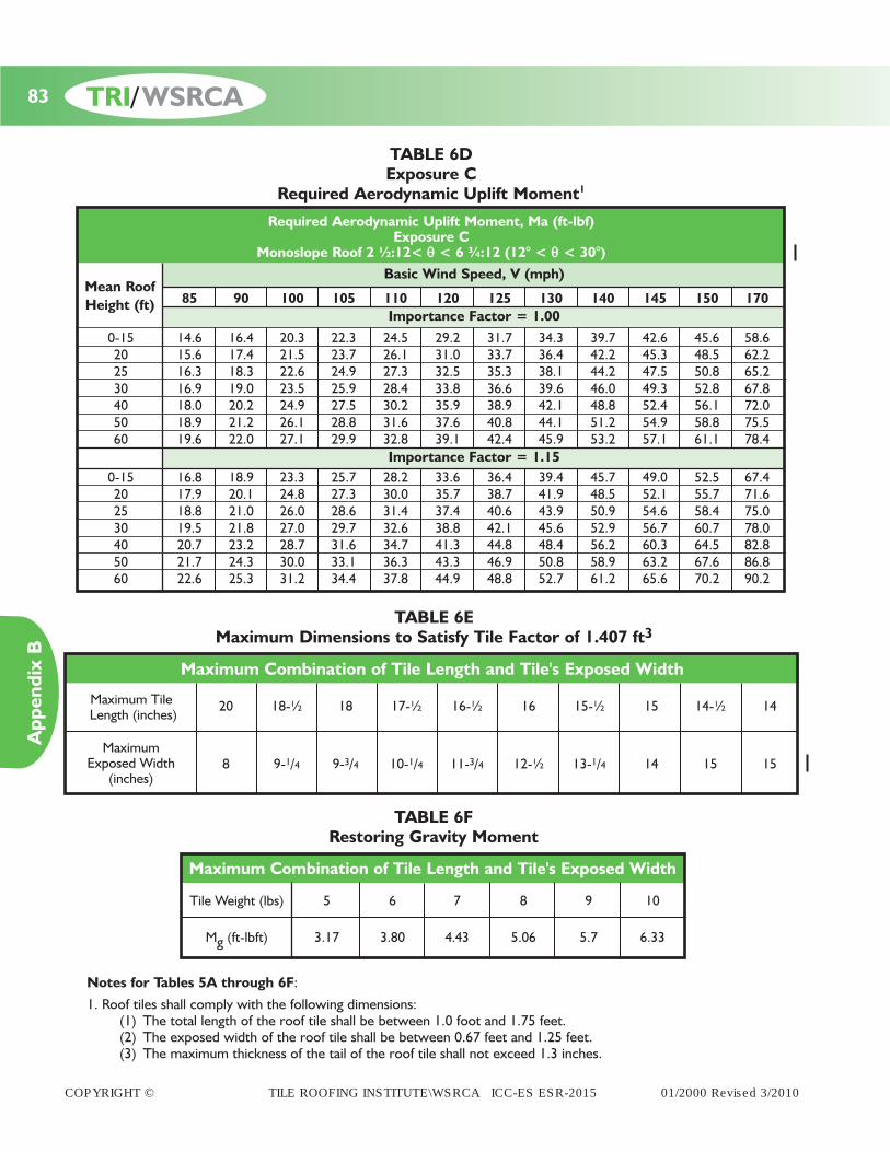
COPYRIGHT © TILE ROOFING INSTITUTE\WSRCA ICC-ES ESR-2015 01/2000 Revised 3/2010
85 90 100 105 110 120 125 130 140 145 150 170
0-15 14.6 16.4 20.3 22.3 24.5 29.2 31.7 34.3 39.7 42.6 45.6 58.620 15.6 17.4 21.5 23.7 26.1 31.0 33.7 36.4 42.2 45.3 48.5 62.225 16.3 18.3 22.6 24.9 27.3 32.5 35.3 38.1 44.2 47.5 50.8 65.230 16.9 19.0 23.5 25.9 28.4 33.8 36.6 39.6 46.0 49.3 52.8 67.840 18.0 20.2 24.9 27.5 30.2 35.9 38.9 42.1 48.8 52.4 56.1 72.050 18.9 21.2 26.1 28.8 31.6 37.6 40.8 44.1 51.2 54.9 58.8 75.560 19.6 22.0 27.1 29.9 32.8 39.1 42.4 45.9 53.2 57.1 61.1 78.4
0-15 16.8 18.9 23.3 25.7 28.2 33.6 36.4 39.4 45.7 49.0 52.5 67.420 17.9 20.1 24.8 27.3 30.0 35.7 38.7 41.9 48.5 52.1 55.7 71.625 18.8 21.0 26.0 28.6 31.4 37.4 40.6 43.9 50.9 54.6 58.4 75.030 19.5 21.8 27.0 29.7 32.6 38.8 42.1 45.6 52.9 56.7 60.7 78.040 20.7 23.2 28.7 31.6 34.7 41.3 44.8 48.4 56.2 60.3 64.5 82.850 21.7 24.3 30.0 33.1 36.3 43.3 46.9 50.8 58.9 63.2 67.6 86.860 22.6 25.3 31.2 34.4 37.8 44.9 48.8 52.7 61.2 65.6 70.2 90.2
TABLE 6DExposure C
Required Aerodynamic Uplift Moment1
Required Aerodynamic Uplift Moment, Ma (ft-lbf)Exposure C
Monoslope Roof 2 ½:12< q < 6 ¾:12 (12° < q < 30°)Basic Wind Speed, V (mph)
Importance Factor = 1.00
Importance Factor = 1.15
Mean RoofHeight (ft)
20 18-½ 18 17-½ 16-½ 16 15-½ 15 14-½ 14
8 9-1/4 9-3/4 10-1/4 11-3/4 12-½ 13-1/4 14 15 15
Maximum TileLength (inches)
Maximum Exposed Width
(inches)
Maximum Combination of Tile Length and Tile's Exposed Width
TABLE 6EMaximum Dimensions to Satisfy Tile Factor of 1.407 ft3
Tile Weight (lbs) 5 6 7 8 9 10
Mg (ft-lbft) 3.17 3.80 4.43 5.06 5.7 6.33
Maximum Combination of Tile Length and Tile's Exposed Width
TABLE 6FRestoring Gravity Moment
Notes for Tables 5A through 6F:
1. Roof tiles shall comply with the following dimensions:(1) The total length of the roof tile shall be between 1.0 foot and 1.75 feet.(2) The exposed width of the roof tile shall be between 0.67 feet and 1.25 feet.(3) The maximum thickness of the tail of the roof tile shall not exceed 1.3 inches.
83
Appendix B
TRI/WSRCA

COPYRIGHT © TILE ROOFING INSTITUTE\WSRCA ICC-ES ESR-2015 01/2000 Revised 3/2010
2. The required aerodynamic uplift moments in these tables are based on a roof tile that has a Tile Factor of 1.407 ft3. The required aerodynamic uplift moment for roof tiles with a Tile Factor other than 1.407 ft3 may be determined by using the following procedure. These tables are conservative for roof tiles with a Tile Factor less than 1.407 ft3.
(1) Calculate the Tile Factor for the desired roof tile.Tile Factor = b (L) (La)
b = exposed width of the roof tile (ft)L = total length of roof tile (ft)La = moment between point of rotation and the theoretical location of the resultant of the wind uplift force.
For the standard roof tiles the moment arm = 0.76 L (See IBC - Section 1609.7.3)(2) Based on exposure, roof style, roof pitch, importance, basic wind speed, and mean roof height select the appro-
priate required aerodynamic uplift moment from the tables for the desired roof tile.(3) Multiply the selected required aerodynamic uplift moment by the ratio of the tile factor for the desired roof tile
and 1.407 ft3.(4) Select an attachment system that is equal to or greater than the calculated required aerodynamic uplift moment
in step 3.3. Table 6E provides a combination of exposed widths and total lengths that generate a Tile Factor of 1.407 ft3. The table "Maximum Combination of Tile Length and Tile's Exposed Width" provides a listing of tiles that fit this Tile Factor.
Notes cont’d from page 83
TABLE 7Allowable Aerodynamic Uplift Moments
Mechanical Fastening Systems
Direct Deck Installation
Roof Tile Profiler15/32" Sheathing (plywood Allowable Aerodynamic
or code approved Uplift Resistanceequivalent) (ft-lbf)
Flat/Low 39.1Medium 36.1High 28.6
Flat/Low 39.1Medium 33.3High 28.7
Flat/Low 50.1Medium 55.5High 51.3
Flat/Low 13.5Medium 12.9High 11.3
Flat/Low 20.2Medium 19.1High 13.1
Flat/Low 25.2Medium 25.2High 35.5
Flat/Low 38.1Medium 38.1High 44.3
2-10d ring shank nails(18-22 rings per inch)
1-#8 screw
2-#8 screws
1-10d smooth or screw shank nail
2-10d smooth or screw shank nails
1-10d smooth or screw shank nail with clip
2-10d smooth or screw shank nail with clip
84
Appendix B
TRI/WSRCA

COPYRIGHT © TILE ROOFING INSTITUTE\WSRCA ICC-ES ESR-2015 01/2000 Revised 3/2010
Direct Deck Installation
Roof Tile Profiler19/32" Sheathing (plywood Allowable Aerodynamic
or code approved Uplift Resistanceequivalent) (ft-lbf)
Flat/Low 46.4Medium 45.5High 41.2
Flat/Low 16.0Medium 15.2High 13.0
Flat/Low 25.0Medium 23.4High 15.4
2-10d ring shank nails(18-22 rings per inch)
1-10d smooth or screw shank nail
2-10d smooth or screw shank nails
TABLE 7 (Cont’d)Allowable Aerodynamic Uplift Moments
Mechanical Fastening Systems
Batten Installation
Roof Tile Profiler15/32" Sheathing (plywood Allowable Aerodynamic
or code approved Uplift Resistanceequivalent) (ft-lbf)
Flat/Low 24.6Medium 36.4High 26.8
Flat/Low 25.6Medium 30.1High 25.5
Flat/Low 36.1Medium 41.9High 37.1
Flat/Low 10.1Medium 8.7High 8.2
Flat/Low 12.8Medium 11.9High 12.7
Flat/Low 27.5Medium 27.5High 29.4
Flat/Low 37.6Medium 37.6High 47.2
2-10d ring shank nails(18-22 rings per inch)
1-#8 screw
2-#8 screws
1-10d smooth or screw shank nail
2-10d smooth or screw shank nails
1-10d smooth or screw shank nail with clip
2-10d smooth or screw shank nail with clip
Notes for Table 7:
1. For attachment systems not listed in the table for 19/32" sheathing use the allowable aerodynamic uplift resistance from the table for 15/32" sheathing.
2. Fasteners shall have a minimum edge distance of 1-½ inches from the head of the tile and located in the pan of the tile to obtain the values in Table 7. Consult the tile manufacturer for additional limitations or restrictions.
Notes cont’d on page 86
85 TRI/WSRCA
Appendix B
COPYRIGHT © TILE ROOFING INSTITUTE\WSRCA ICC-ES ESR-2015 01/2000 Revised 3/2010
Notes for Table 7(Cont’d):
3. Ring shank nails shall be 10d ring shank corrosion resistant steel nails with the following minimum dimensions: (3 inches long, 0.283 inch flat head diameter, 0.120 inch undeformed shank diameter or 0.131 inch screw diameter).
4. Smooth or screw shank nails shall be 10d corrosion resistant steel (with the following minimum dimension. 3 inch long, 0.283 inch flat head diameter, 0.120 inch undeformed shank diameter or 0.131 inch screw diameter).
5. Screws are #8 course threaded, 2.5 inches long corrosion-resistant steel wood screws conforming to ANSI/ASME B 18.6.1.
6. The fastener hole nearest the overlock shall be used when a single nail or screw is required. The fastener hole nearestthe underlock and the fastener hole nearest the overlock shall be used when two nails or screws are required.
7. When using eave and field clips, attachment of the tiles is accomplished by a combination of nails and clips. Tiles arenailed to the sheathing or through the battens to the sheathing with one or two 10d corrosion resistant nails (Note 2 and 3 above) as required by Tables 5 and 6. Additionally, each tile is secured with a 0.060 inch thick and 0.5 inch wide clip which is secured to the plywood sheathing or eave fascia, as appropriate, with a single nail per clip. The nail shall be placed in the hole closest to the tile for clips having more than one nail hole. The following clip/nail combinations are permitted:
(1) Aluminum alloy clip with 1.25 inch HD galvanized roofing nail (0.128 inch shank diameter).(2) Galvanized steel deck clip with 1.25 inch HD galvanized roofing nail (0.128 inch shank diameter).(3) Stainless steel clip with 1.25 inch HD galvanized roofing nail (0.128 inch shank diameter).
8. Field clips and eave clips are to be located along the tile where the clip's preformed height and the tile's height abovethe underlayment are identical.
9. Counter batten values not included.10. For attachment systems not listed in table for 19/32 inch sheathing, use allowable aerodynamic uplift moment from
table for 15/32 inch sheathing.11. The allowable aerodynamic uplift moments include a generic restoring gravity moment of 6.5 ft-lbf for a direct deck
installation and a generic restoring gravity moment of 5.5 ft-lbf for a batten installation."
Additional Notes [outside the scope of ICC-ES report (ERS-2015P) on this manual]
Allowable Aerodynamic Uplift MomentsAdhesive Fastening Systems
Refer to the adhesive manufacturer for the allowable aerodynamic uplift moment for the installation method used tocomply with the applicable code requirements. Installation of roof tiles using the adhesive system should be done bytechnicians trained and having a current certification by the adhesive manufacturer to comply with the applicable coderequirements.
Allowable Aerodynamic Uplift MomentsMortar Fastening Systems
Refer to the pre-bagged mortar mix manufacturer for the allowable aerodynamic uplift moment for the installation methodused to comply with the applicable code requirements. Mixing of mortar at the jobsite is not a recommended practice.Installation of roof tiles using the mortar system should be done by technicians trained and having a current certificationby the mortar mix manufacturer to comply with the applicable code requirements.
Design Considerations for Installations in Earthquake Regions[Outside the scope of ICC-ES report (ERS-2015P) on this manual.]
The Tile Roofing Institute in conjunction with the Universityof Southern California, Structural Engineering Departmentconducted a series of testing on the Seismic Performance ofConcrete and Clay Tile. The testing concluded thatConcrete and Clay tile, when installed according to ICCcode requirements, withstood forces almost twice the coderequirements for structures.
Tile is the only roofing material to have conducted suchtesting on roof assemblies and is pleased to report thatconcrete and clay tile will not require any additional fas-tening requirements, other than those required under thecurrent ICC code.
86TRI/WSRCA
Appendix C
COPYRIGHT © TILE ROOFING INSTITUTE\WSRCA ICC-ES ESR-2015 01/2000 Revised 3/2010
Abutment: The intersection between the roof and thechimney, wall or other vertical face.
Adhesives: A bonding agent to join two surfaces for thepurpose of permanent attachment as approved by thelocal building official.
Anti-Ponding: A device such as beveled cant strip or shop-formed sheet metal is recommended at all raised fasciaconditions to support the underlayment.
Batten: A nonstructrual horizontal fastening strip to whichthe roof tiles are attached.
Batten Lugs: Protrusions (anchor lugs) on the underside ofthe tile designed to engage over the upper edge of tilingbattens.
Bedding: Refers to the installation of roof tiles to a mortaror adhesive foam patty and is structural in nature for thebasic securement.
Bird Stop: A product used at the eave of a profile tile roofto stop birds from entering below the tile.
Booster Tile: Normally 3"-4" long tile strip used to lift upthe cover tile. Sometimes it is used in boosting up field tileto create an authentic looking roof.
Cant Angle: The angle formed between the upper surfaceof the installed roof tile and the roof deck.
Clay Rooftile: An interlocking or non-interlocking clay roofcovering, used to cover the roof surface.
Concrete Rooftile: An interlocking, or non-interlockingconcrete roof covering, used to cover the roof surface.
Counter Battens: Vertical furring strips running beneathand perpendicular to horizontal tile batten, to allowdrainage and air flow beneath the roof tile. Also known asstrapping.
Counter Flashing: A flashing material that provides theenclosure at the transition line between the roof to wallflashing at intersecting vertical surfaces.
Counter Batten System: A method of elevating horizontalbattens above the roof deck to allow drainage and air flow
beneath the horizontal battens and roof tile
Cricket: See Saddle.
Dead Loads: The weight of all materials of constructionincorporated into the roof assembly including but not lim-ited to, fixed service equipment, roof tiles, battens,underlayment, flashing, roof deck, etc.
Direct Deck: Those tiles fastened directly to the roof deckwithout the use of battens.
Eave: Outer edge of the roof downslope.
Eave Closure: A material available for S-tile or Pan andCover tile. Eave closures are used to close the convexopening created by the shape of the tile at the eave. Thisaccessory also provides the proper rise for the firstcourse of tile. See Bird Stop.
Eave Riser: Method/material used for elevating the nose ofthe first course of tile to the plane of the field tile.
Fascia: A decorative board concealing the lower ends ofthe rafters or the outer edge of the gable.
Flashing: Impervious material used to cover, waterproof,and direct water away from roof penetrations and fromintersections between the roof tile and other materials.
Fully Engaged: The horizontal batten material thicknessshall be equal to or greater than the design depth of theanchor lug of the tile.
Gable End: The generally triangular area at the end of asloped roof extending from the eaves to the ridge.
Head Lap: The measurement of the overlap between acourse of roofing components and the course above.
Headwall Flashing: The flashing that is installed at thehorizontal, intersecting wall or other vertical surface.
Hem: An edge of metal bent back on its self to givestrength to the edge of the metal.
High Profile Tile: Those tiles having a rise to width ratiogreater than 1:5. (Typically referred to as “S” or barrel,2-piece, Pan & Cover tile). Measured in the installedcondition.
GLOSSARY OF TERMS
87
Appendix C
TRI/WSRCA

COPYRIGHT © TILE ROOFING INSTITUTE\WSRCA ICC-ES ESR-2015 01/2000 Revised 3/2010
Hip: The exterior sloping ridge formed by the intersectionof two inclined roof surfaces.
Hip/Ridge Tile: Accessory trim tile used to cover a hip ora ridge.
Hip Starter: The closed hip piece which is used at the out-side corner, intersecting of two eaves to start the hip tile.
Interlocking Tile: Those tiles with a system of rib(s) orgroove(s) enabling the joining of adjacent tiles in thesame horizontal or vertical row, with the overlapping lockcovering the underlapping lock.
Length: The maximum overall dimension of the tiles asmeasured parallel to the water course.
Live Loads: A load produced by the use and occupancy ofthe building or other structure that does not include con-struction or environmental loads, such as wind load, snowload, rain load, earthquake load, flood load, or dead load.
Low Profile Tile: Low profile tiles are defined as those flattiles having a top surface rise equal to or less than ½".
Medium Profile Tile: Tiles having a rise greater than ½" anda rise to width ratio of less than or equal to 1:5.
Metal Drip Edge: Perimeter metal flashing installed to pro-tect raw edges of roof deck.
Mortar: A mixture of cementitious material, aggregate,and water used for bedding, jointing, and bonding ofmasonry or roof tile and accessories.
Nail Hole: A small opening passing partially or totallythrough the tiles to allow the penetration of a nail, screwor other approved fastener for the purpose of fasteningthe tile to a support.
Nailer Board/Stringer: A piece of wood or other material ofproper height, attached to a roof at the ridge and/or hipsto allow for proper support and means of attachment forthe hip and ridge tile. Can also be used in pan and coverapplications under the cover tile for proper support.(Commonly known as a vertical stringer)
Non-Interlocking Tile: Those tile that do not have verticalrib(s) or grooves creating an interlocking tile.
Nose Clips: A fastening device designed to hold the nose(or butt) end of the tile against uplift or sliding down theslope. Also known as wind clips or tile locks.
Nose Lugs: Protrusion(s) on the underside of the tile thatare designed to restrict the flow of weather between twoconsecutive courses of tile.
Pan and Cover Tile: Semi-circular shape tile. Also known astwo piece mission or barrel mission tile. There aretapered and straight two piece mission styles available.
Pan Flashing: Metal flashing running under the tile at theside walls.
Point-up: The application of mortar to fill voids to variousends, sides and angles of a tile roof, which are non struc-tural in nature.
Profile: The contour of the top surface of the tiles whenviewed from the nose end.
Rake Trim: A roof tiling accessory used to cover the inter-section between the gable end and a roof.
Ridge Trim: The piece of ridge available to close off thegable end and peak of a roof. Some ridge tile have aninterlocking feature and require either a “starter” or“finisher”.
Ridge Tile: See hip/ridge tile.
Roof Live Load: A load on the roof produced (1) during themaintenance by workers, equipment, and materials and(2) during the life of the structure by moveable objects,such as planters or other similar small decorative appur-tenances that are not occupancy related.
Saddle Flashing: The flashing at the upper intersectionbetween a chimney or skylight and the roof. (Commonlyreferred to as a Cricket or Backpan)
Side Clips: A fastening device for tile with a side interlockdesigned to prevent rotation of the tile when subjected touplifting forces. Also known as hurricane clip.
88
Appendix C
TRI/WSRCA

COPYRIGHT © TILE ROOFING INSTITUTE\WSRCA ICC-ES ESR-2015 01/2000 Revised 3/2010
Side Lap: The measurement of the overlap between aroofing component and a component to one side of it.
Side Wall: The vertical intersection that runs parallel to theroof slope.
Spaced Sheathing: Sheathing boards or battens, which aremechanically attached to the rafters or framing members,with gaps or spaces between them and is used in lieu of asolid sheathing.
Standard Weight Rooftile: Roof tile of mass/unit area of 9lbs/ft2 or greater installed weight excluding all other roof-ing components.
Starter Tile: First course of cover tile for two piece misson.Normally 3"-4" shorter than the field tile.
Step Flashing: A piece of flashing material covering eachcourse of tile at sidewalls.
Stringer: See nailer board.
Sweat Sheet/Bleeder Sheet: A layer of underlayment underthe valley metal to prevent moisture/condensation fromentering the roof deck.
Tile Course: The horizontal increment of exposure.
Tile Thickness: Any vertical measurement of the cross sec-tion of the tiles excluding the lapping area, head or noselugs, and weather checks.
Tile Thickness (visual): The overall thickness of the tileprofile when installed as measured from the top surfaceof the lower tile to the top surface of the upper tile.
Tile Batten: See Batten
Underlayment: A water shedding membrane installedover the roof sheathing, rafters, or trusses. The under-layment may be rigid or roll form.
Valley: The angle of a roof where two slopes intersectinternally.
Closed Valley: Where tile(s) are cut to meet at thecenter of the valley metal.
Open Valley: Where tile(s) are cut to expose thetrough area of the metal.
Vent Tile: A tile designed to allow air circulation from theroof space to the outside.
Water Course: The valley portions of profiled tiles alongwhich water drains.
Weather Blocking: A barrier of moldable or preformedrigid material which blocks the entry of wind drivenmoisture at openings between the field tile and trim tileor the field tile and roof flashing.
Weather Checks: Protrusion(s) on the tile that are designedto restrict the flow of water between two consecutivecourses of tile.
Width: The maximum overall dimension of the tiles asmeasured perpendicular to the length of the water channel.
Width, Exposed: The maximum overall dimension of thetile as measured perpendicular to the length of the waterchannel minus the side lap of the adjacent roof tile.
Wire Tie System: A roof tile fastening system approved bythe local building code, that limits the penetration of theunderlayment and allows tile to be fastened to non-nailable roof decks.
89
Appendix C
TRI/WSRCA

230 East Ohio, Suite 400Chicago, IL 60611312.670.4177www.tileroofing.org
Western States Roofing Contractors Association465 Fairchild Drive, Suite 210Mountain View, CA 94043800.725.0333www.wsrca.com