conceptualization of an exoskeleton continuous...
TRANSCRIPT
Conceptualization of an exoskeleton Continuous Passive Motion(CPM) device using a link structure
Kyu-Jung Kim1, Min-Sung Kang2 Department of Intelligent Robot Engineering1 and
Department of Mechatronics Engineering2 Hanyang University1,2
Seoul, Republic of Korea1,2 [email protected], [email protected]
Youn-Sung Choi1, Jungsoo Han2 and Changsoo Han3 Department of Mechanical Engineering1,3 and Department
of Industrial & Mechanical System Engineering2 Hanyang University1,3 and Hansung University2
Seoul, Republic of Korea1,2,3 [email protected], [email protected] and
Abstract—This study is about developing an exoskeleton Continuous Passive Motion (CPM) with the same Range of Motion (ROM) and instant center of rotation as the human knee. The key feature in constructing a CPM is an accurate alignment with the human knee joint enabling it to deliver the same movements as the actual body on the CPM. In this research, we proposed an exoskeleton knee joint through kinematic interpretation, measured the knee joint torque generated while using a CPM and applied it to the device. Thus, this new exoskeleton type CPM will allow precise alignment with the human knee joint, and follow the same ROM as the human knee in any position.
Keywords-component; Continuous Passvie motion(CPM); Knee joint; Exoskeleton; Total Knee Arthroplasty(TKA); Rehabilitation; Range of Motion(ROM)
I. INTRODUCTION Continuous Passive Motion (CPM) is a knee rehabilitation
device used to recover the range of motion (ROM) or to lessen edema and swelling of the knee following surgeries associated with knee joint diseases like knee replacement arthroplasty or reconstruction of the cruciate ligament. This manual motion device is a manual rehabilitation physical exercise device by helping the joints move gradually, therefore recovering the ROM of the knee.
Salter initially defined this kind of manual rehabilitation exercise, reporting that the immobilization treatment was injurious to the joints and therefore moving the joints occasionally was more effective[1]. There have been many different opinions regarding the CPM treatment since then. According to the comparison study between groups receiving physical modalities and CPM treatment, there were not any notable ROM changes or differences in pain[2]. There was a difference 2 weeks after the surgery for the group which received CPM treatment regarding ROM recovery, but there was not an eminent distinction with the physical modalities after the 2 weeks. These manual joint exercise devices were only different in their approach method compared with the immobilization treatment[3]. Nevertheless, even though it was only for a short period of time, CPM treatment pathologically minimized the stiffness in the joints compared to the immobilization method. The pathological CPM treatment
repeats flexion and extension exercises manually in order to promote the circulation of the blood and maximize the rehabilitation process in a short period of time. This process helps minimize hemiarthrosis and periarticular edema around the joints after external injury and surgery of the knee[4]. On account of this, using the CPM method decreases the number of times visiting hospitals and thus continues to rise in its usage. The existing CPM device intends to follow the exact ROM of the human body, but according to the previous reports, it does not succeed. The previous studies compared the ROM of the knee with the CPM using motion capture devices and electrogoniometers. In the study comparing ROMs of 4 CPM devices and that of the actual knee using motion capture devices showed that the actual ROM was shorter than those of the CPM devices, and the alignment of the human body and the CPM was not accurate, resulting in error. The study using eletrogoniometers was to figure out the correlation between the angle of a bed and the human knee ROM. Since CPM devices are used mostly in bed, the experiments were carried out under the same conditions, while changing the angles of the beds. Differences in angles brought out differences in the hip joint angles which affected on the ROM of the knee. From these two studies, we can conclude that the accurate alignment between the knee joint and the CPM joint, and the identical ROM embodiment of the human knee are the most important requirements for knee rehabilitation[5-6].
In this study, we have analyzed the kinematic joint movements of the knee and the CPM using the four-bar linkage structure. This is then applied to the designing of the CPM knee joint with a ROM similar to that of a human knee. In addition, we estimated the torque needed to put the CPM in motion based on the human body measurements. Also, we have calculated the torque of the human knee joint and conceptualized the CPM and the simulation of it through experiments. We have used the linear actuator to put the CPM in motion which had an advantage over rotary motors that took up much space around the axis and also space between the legs, causing the user to be in an uncomfortable position. This allowed the users to utilize the device in various positions.
II. HUMAN KNEE MODEL
A. The Linkage Structure of Human Knee Joint
This research was supported by the Happy tech. program through the National Research Foundation of Korea(NRF) funded by the Ministry of Education, Science and Technology (No. 2010-0020487).
2011 IEEE International Conference on Rehabilitation Robotics Rehab Week Zurich, ETH Zurich Science City, Switzerland, June 29 - July 1, 2011
978-1-4244-9861-1/11/$26.00 ©2011 IEEE 1024

Figure 1. Schematic illustration of Knee joint motion.
Figure 2. The diagram of the four-bar linkage ABCD is superimposed, representing the Anterior(AB) and Posterior(CD) cruciate ligaments, the Femur(CB) and Tibial(AD) rigid bond links. I represents the instantaneous centre of flexion[8].
The human knee joint is composed of a medial tibiofemoral joint, lateral tibiofemoral joint, and a patellar. It flexes and extends from the sagittal plane, and rotates internally and externally in the horizontal place. We only focused on flexion and extension on the sagittal plane excluding internal rotation and external rotations. Shown in Fig.1, flexion and extension in the knee are not fixed on the medial and lateral axes, but rather generated in a rolling and sliding manner on the femoral condyle. This pathway is called evolute or instant center of rotation which biomechanically changes the length of the internal moment arm[7]. This knee structure can be presented as a four-bar linkage model in the sagittal plane which enables the analysis of the changes in the instant center of rotation and the ROM of the femur and tibia.
Fig.2 is a four-bar linkage model of the human knee cruciate ligament, AB being the anterior cruciate ligament (ACL), CD being the posterior cruciate ligament (PCL). AD and BC is a link structure between tibia and femur, and the angle between the tibia link and the femur link indicates the angle of the knee joint. Instant center of rotation of the knee is strong index. The instant center of rotation is an important index that presents the knee motion. The knee angle and the center of rotation is changed simultaneously, and these positioning change makes trajectory of ICR in knee. These ICR is consisting of ACL and PCL, also the cross point of the ligaments is ICR I. When it is looked on the horizontal plane, It
Figure 3. Knee joint of “Screw-home” motion.
Figure 4. Configuration of the center of mass of the lower leg.
is formed at the center of the human joint. However, as shown in Fig.3, because of the different circular shape between medial and lateral condyles, it makes each different trajectory. In the medial condyle, the rotation of “screw-home’ appears, Screw-home is influenced by the shape of the medial condyle, the passive tension at ACL, and external traction of quadriceps femoris. As a result, the external rotation appears when the knee joint is in full extension[11-12]. As mentioned above, however, only the flexion and extension on the sagittal plane were considered in this study. The exercises other than flexion and extension were excluded to ensure mental and physical calmness of the patient because this training was conducted for rehabilitation and for the patient to adapt to the artificial joint after its insertion. Therefore, this can somewhat differ from the actual motions on the knee joint. Unnecessary rotation on the knee can also cause secondary damage[13].
In this research, we predicted the changes of the instant center of rotation and estimated the ROM through the four-bar linkage structure, applying it to the designing of the CPM joints.
B. A Leg Model to Calculate the Knee Joint Torque The CPM to be developed will be universal, and not be
customized. The statistical human measurement data were used to select the actuator.
We have collected data from 11 musculotendinous units for the knee model used in this study and composed the geometrical leg model based on cadaver data. Fig.4 is a human body model 175 centimeters in height, 746N in weight and shows the length, mass, and center of mass of each part in a
1025
sagittal plane[9]. To compute the moment of the knee joint, we calculated the location of the center of mass of the lower leg which leads to the moment of the lower leg .
Supposed that the segment 1 is shank and the segment 2 as foot, each moment arm about the center of mass belong to the segment 1 and 2 can be x1 and x2; the mass of each segment is W1 and W2. According to the conventional calculation method about the moment of force, the center of mass point can be derived by the equation (1). So as to explore the critical design requirement of the proposed system, the minimum nominal torque can be estimated through the equation (2).
1 1 2 2
1 2cg
x W x WxW W
+=+
(1)
1 2( )O cgM W W x= + (2)
III. CONCEPTUAL DESIGN
A. Designing the CPM Exoskeleton Knee Joint We collected cadaver knee joint data to design a ROM
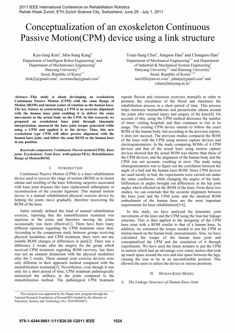
identical to the human knee[8]. The CPM moves in a way that tibia flexes and extends against the femur in the sagittal plane. We ignored the screw-home rotational movement in the knee joint and designed it in a two-dimensional plane. Fig.5 is a knee joint using the CPM four-bar linkage structure in which l4 represents the anterior cruciate ligament, l2 represents the posterior cruciate ligament, l1 and l3 represents the adhesive points of the femur and tibia. We have designed the exoskeleton CPM knee joint taking into consideration that the human knee joint is endoskeleton. Through using the suggested method form from Walker et al. (1985) model, the design parameters for the exoskeleton model were determined[14-16], therefore equations (3) and (4) are derived. [mm]
1 2 4 3L L L L+ = + (3)
2 21 2
2 2
3 34 4 4 3
3 34 4
cos sinsin cos0 0
cos sincos sinsin cossin cos 0 0
θ θθ θ
θ θθ θθ θθ θ
−⎡ ⎤⎡ ⎤ ⎡ ⎤+ ⎢ ⎥⎢ ⎥ ⎢ ⎥
⎣ ⎦ ⎣ ⎦⎣ ⎦−− ⎡ ⎤⎡ ⎤ ⎡ ⎤ ⎡ ⎤
= + ⎢ ⎥⎢ ⎥ ⎢ ⎥ ⎢ ⎥⎣ ⎦ ⎣ ⎦⎣ ⎦ ⎣ ⎦
(4)
These kind of four-bar linkages have the most similar ROM to the human body, whereas monocentric and polycentric hinges which are widely used in orthotics tend to differ in alignment with the human body greatly as the bent angle increases[10].
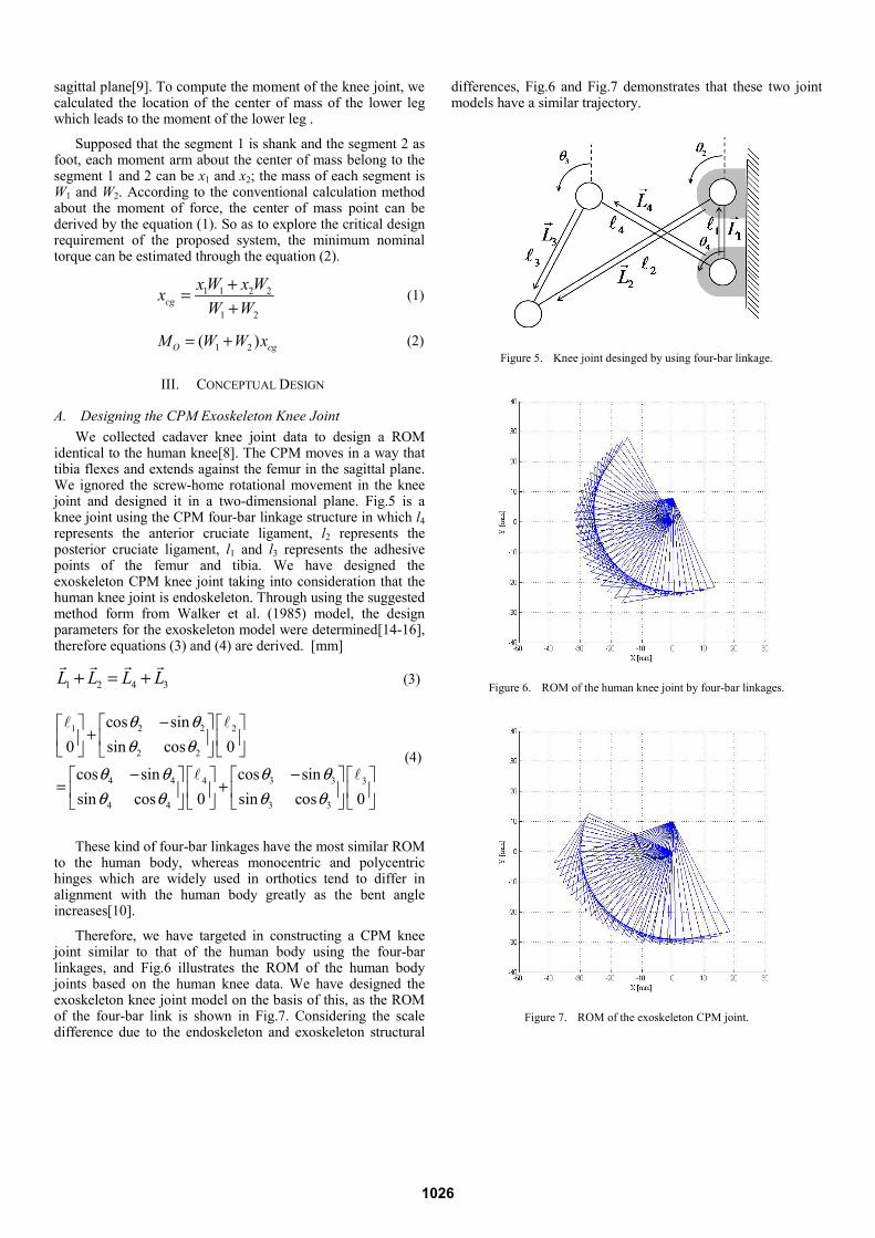
Therefore, we have targeted in constructing a CPM knee joint similar to that of the human body using the four-bar linkages, and Fig.6 illustrates the ROM of the human body joints based on the human knee data. We have designed the exoskeleton knee joint model on the basis of this, as the ROM of the four-bar link is shown in Fig.7. Considering the scale difference due to the endoskeleton and exoskeleton structural
differences, Fig.6 and Fig.7 demonstrates that these two joint models have a similar trajectory.
Figure 5. Knee joint desinged by using four-bar linkage.
Figure 6. ROM of the human knee joint by four-bar linkages.
Figure 7. ROM of the exoskeleton CPM joint.
1026

B. Designing the CPM Driving Mechanism The position of the actuator was first considered to select
the actuator for knee rehabilitation, and the actuator was selected considering the load that influences the knee rehabilitation and the posture that limits the ROM. We used the linear actuator to operate the CPM exoskeleton knee joint. The range of motion was from -45 degrees to 95 degrees which is the same as the human knee joint[7]. However, a mechanical problem arises since it is difficult to embody an ROM of -45 to 95 degrees with a short 100 millimeter stroke. Therefore, we designed the device as a synthesis of mechanical linkage between the CPM exoskeleton knee joint and the linear actuator to solve this problem. Fig.9 illustrates the entire body of the CPM control link structure. Input is delivered to the control links through the linear actuator while output is produced in the form of back-and-forth motion by rotating l3. The link structure can be divided into two main parts. One being the upper part, comprised of four-bar linkage system as seen on Fig.10, and modeled as equations (5) and (6).
10 6 9 8L L L L+ = + (5)
1 6 6 6
10 6 6
9 9 8 87 8
9 9 8 8
/ 2 cos sinsin cos 0
cos sin cos sinsin cos sin cos0 0
θ θθ θ
θ θ θ θθ θ θ θ
−⎡ ⎤ ⎡ ⎤ ⎡ ⎤+⎢ ⎥ ⎢ ⎥ ⎢ ⎥
⎣ ⎦⎣ ⎦ ⎣ ⎦− −⎡ ⎤ ⎡ ⎤⎡ ⎤ ⎡ ⎤
= +⎢ ⎥ ⎢ ⎥⎢ ⎥ ⎢ ⎥⎣ ⎦ ⎣ ⎦⎣ ⎦ ⎣ ⎦
(6)
The other, lower part as seen on Fig.11 is a composition of exoskeleton CPM knee joint and four-bar linkages. θ6,θ9,θ8 can be derived from equation (6) by the input force transmitted through the linear actuator. θ3,θ4 on the CPM exoskeleton knee joint can be derived from equation (4). Therefore, by getting θ5 from equations (7) and (8), we are able to calculate the ROM of the CPM.
4 3 5 1 6 7/ 2L L L L L L+ + = + + (7)
3 34 4 4 3
3 34 4
5 5 5
5 5
6 6 7 71 6 7
6 6 7 7
cos sincos sin / 2sin cossin cos 0 0
cos sinsin cos 0
cos sin cos sinsin cos sin cos0 0 0
θ θθ θθ θθ θ
θ θθ θ
θ θ θ θθ θ θ θ
−− ⎡ ⎤⎡ ⎤ ⎡ ⎤ ⎡ ⎤+ ⎢ ⎥⎢ ⎥ ⎢ ⎥ ⎢ ⎥
⎣ ⎦ ⎣ ⎦⎣ ⎦ ⎣ ⎦−⎡ ⎤ ⎡ ⎤
+ ⎢ ⎥ ⎢ ⎥⎣ ⎦⎣ ⎦
− −⎡ ⎤ ⎡ ⎤⎡ ⎤ ⎡ ⎤ ⎡ ⎤= + +⎢ ⎥ ⎢ ⎥⎢ ⎥ ⎢ ⎥ ⎢ ⎥⎣ ⎦ ⎣ ⎦ ⎣ ⎦⎣ ⎦ ⎣ ⎦
(8)
IV. EXPERIMENT AND SIMULATION In this study, we have suggested an exoskeleton structure
combined with links and determined the torque to run the device to create the equal alignment and the identical ROM as
the human knee. To select actuators that can drive proposed model. We measured torque occurring in knee joint.
Figure 8. Structure of the CPM linkage.
Figure 9. Upper linkage structure of the CPM driving mechanism.
Figure 10. Lower linkage structure of the CPM driving mechanism.
1027

A. Measuring the Human Knee Joint Torque using Muscular Power Measuring Apparatus
From the sagittal plane, the knee flexes and extends. These two movements were analyzed with a muscular strength measuring apparatus Kin-Com in the Fig.11 to evaluate the knee joint torque. The subjects of the experiment were 13 healthy men with an average age of 28.4, average weight 76kg, average height 173.2 cm which were similar to the human body data. This experiment was set on a passive isokinetic mode, under a velocity of 10 RPM and performed 5 sets of 10 times. The force measured by the load sell fixed on the Kin-Com arm was multiplied to the Moment arm which leads to the torque of the knee joint. The highest torque was 22.40Nm as seen on Fig.13. The average of the highest torques among the subjects was 14.45Nm, the lowest torque was recorded at 8.55Nm. The CPM can be used by the aged who underwent the knee replacement arthroplasty because of osteoarthritis. The actuator was finally selected considering the users and safety factor. The actuator of CPM is typically driven at a speed of 10 RPM or less, and it was considered in this study. A low speed is used for the CPM to ensure mental calmness of the user and prevent secondary damage after operation. An unnecessarily high speed may cause discomfort and strong pain to the user[3-4].
Figure 11. (right) ROM of Kin-Com (left) Experiment.
Figure 12. The highest torque value through the Kin-Com experiment.
B. Measuring the ROM using a Linear Actuator Through experiments, we have calculated the torque needed
to drive the CPM. On the basis of this, we have determined the force of the linear actuator and designed the CPM as seen on Fig. 13. We designed the CPM by 3D design tool Solidworks and used the Recurdyn to figure out the movements of the links and the differences in angle followed by the stroke changes of the linear actuator. Fig.14 shows the angles in l5 when the linear actuator is set in motion. It demonstrates the same ROM as the human body. Fig.15 shows the angle differences of the 4 links under a same condition. In order for l5 to rotate 140 degrees, the first link(l9) has to rotate about 30 degrees. Stroke were limited because a linear actuator was used, but the ROM that was the same as that of the knee joint was realized using the link combination structure. The link structure amplifies the relative angle between the input and output angles to produce a gain.
Figure 13. The design of the exoskeleton CPM.
Figure 14. The angle changes follwing the linear actuator stroke change.
Figure 15. The angle changes on each links following the linear actuator stroke.
1028

V. RESULT In this study, we developed a CPM exoskeleton knee joint
with the same instant center of rotation trajectory as the human body, and designed the links so as to follow the same ROM as the human knee. This linkage system produced a big movement even with a slight stroke change made by the linear actuator. In fact, as a result of the simulation, 85mm stroke displacement was needed to attain a ROM ranging from -45 degrees to 95 degrees. Also, to estimate the torque generated on the human knee joint when the lower leg undergoes a passive exercise, we measured the torque from the human body data, collected the simulation results wearing the exoskeleton device, and evaluated the actual torque of human body with a muscular strength measuring device. We determined the spec of the linear actuator from this torque, and confirmed in the simulation that the links move in the same angles as the ROM of the human knee.
VI. CONCLUSION In this research, we solved the difficulties such as the
discordance between the existing CPM joints and the human body joints, and the evidently small ROM in existing CPM devices. Also, we designed the exoskeleton type CPM to benefit the wearer. Based on the theoretical and experimental results of this study, we designed the exoskeleton knee joint and proved that the composition of the driving and subordinate links has the similar ROM to that of the human body knee joints.
REFERENCES
[1] E. Burke Evans, G. W.N. Eggers, James K. Butler and Johanna Blumel, “Experimental Immobilization and Remobilization of Rat Knee Joints,” J Bone Joint Surg Am, vol. 42, pp.737–758, 1960.
[2] Fredrik Montgomery, Malou Eliasson, “Continuous passive motion compared to active physical therapy after knee arthroplasty,” Acfa Orthop Scand, vol. 67, pp.7–9, 1996.
[3] B. Lucie, M. Sarah, W. George, “ Efficacy of Continuous Passive Motion Following Knee Arthroplasty: A metaanalysis,” The Journal of Rheumatology.vol.33, pp.2252–2264, 2004.
[4] W. Shawn, J. Nicholas, “Continuous passvie motion (CPM): Theory and principles of clinical application,” The Journal of Rehabilitation Research and Development, vol.37(2), pp.179–188, 2000.
[5] E. Jesse, BS. Bible, K. Andrew, “Actual Knee Motion during Continuous Passive Motion Protocols is Less Than Expected,” Clin Orthop Relat Res, vol.467, pp.2656–2661, 2009.
[6] Won Man Park, Yoon Hyuk Kim, “Analysis of Range-of-Moition in Continuous Passive Motion Rehabilitation,” Conference on The Korean Society of Mechanical Engineers, vol.11, pp.1515–1517, 2008.
[7] A. Donald Neumann, David Neumann, Kinesiology of the Musculoskeletal System: Foundations for Physical Rehabilitation. pp.472–499.
[8] Vincenzo Parenti-Castelli, Alberto Leardini, Raffaele Di Gregorio, J. John, “On the Modeling of Passive Motion of the Human Knee Joint by Means of Equivalent Planar and Spatial Parallel Mechanisms,” Autonomous Robots, vol.16 , pp.219–232, 2004.
[9] B. Kevin, Shelburne, G. Marus, Pandy, “A Musculoskeletal Model of the Knee for Evaluation Ligament Forces during Isometric Contractions,” J. Biomechanics, vol.30. pp.163–176, 1997.
[10] L. Pnons, Wearable Robots: biomechatronic exoskeleton. pp.75–79. [11] Michal Kozanek, Ali Hosseini, Harry E.Rubash, “Tibiofemoral
kinematics and condylar motion during the stance phase of gait,” Jounal of Biomechanics, vol.42, pp.1877-1884, 2009.
[12] Mirza Biscevic, Mujo Hebibovic and Dragica Smrke, “Variations of Femoral Condyle Shape,” Coll.Antropol, vol.29, pp.409-414, 2005.
[13] Young-Hoo Kim, Keun-Soo Sohn and Jun-Shik Kim, “Range of Motion of Standard and High-Flexion Posterior Stabilized Total knee Prostheses. A Propective, Randomized study.” The Jounal of Bond & Joint surgery, vol.87. pp.1470-1475, 2005.
[14] H.Kurosawa, P.S. Walker, S.Abe, A.Garg and T. Hunter, “Geometry and motion of the knee for implant and orthotic design.” The Jounal of Biomechanics. vol.18, pp.487-499, 1985.
[15] Jose Maria Baydal, Juan manuel, Jaime Pastor, “Development of a hinge compatible with the kinematics of the knee joint,” Prosthetics and Orthotics International, vol.31, pp.371-383, 2007.
[16] Walker PS, Kurosawa H, Rovick Js, Zimmermans RA, “ External knee joint design based on normal motion,” J rehabil Res, vol.22, pp.19-22, 1985.
1029