conceptual - san onofre safety
TRANSCRIPT

CONCEPTUAL PROJECT ASSESSMENT
,,, CPA NO. 97-42
, I . .
) TITLE: SPENT FUEL POOL ISLAND PROJECT i COST ESTIMATE: $4,353,627
ORIGINATOR: W. Henries & SFPl Engineering DATE: 1019197 ENGINEERING PROJECT MANAGER: S. Dahlgren DATE: iohf9F ENGINEERING SECTION HEAD REV EN: W. h DATE: m/3 97 COGNIZANT PSS REVIEW: - 4 ; %r DATE: / ~ ~ / 6 7 PURPOSE/PROBLEM(S): This CPA describes the work required to create a Spent Fuel Pool Island (SFPI). The purpose of the SFPl creation is to permit, along with other planned activities, the unencumbered dismantling of the remainder of the Maine Yankee plant. A conceptual overview of the proposed SFPl is provided on the following pages and more thorough descriptions of the proposed installations are provided in Attachment A of this CPA.
RECOMMENDATION(S): Proceed with the SFPl design and construction as described in this CPA. Due to the requested expedited schedule of this effort, final design details will be developed and approved by the SFPt Project Team.
PROJECTED SCHEDULE: CPA approval 10116197; EDCR PORC approval 12/31/97; Installation & Testing complete 3130198.
ATACHMENTS: (1)Completed Team Assignment sheet (2)PAR and SFPl Cost Benefit Analysis (In
) lieu of Financial Analysis Form), (3)Estimated REM exposure sheet, (A) SFPl Design Details
ROUTING FOR APPROVAL:
1. APPLICABLE ENGINEERING MANAG
2. PLANT MANAGER:
5. PRESIDENT:
COMMENTS BY MANAGEMENT:
L 3 - H A b& h l , B U f A L L kG?4
1 EZ.!CU?Si.!fiE 8 Procedure No. 17-301 Rev. No. 6 ?AGE 1

CPA No. 9742 Page 2
PURPOSE (continued):
As the decommissioning and dismantling of Maine Yankee proceeds, the current spent fuel pool ( S i p ) support systems (i.e. PCCWISW for pool cooling, electric power, building HVAC, etc.) will be gradually removed and replacement components and systems will have to be installed to allow safe operation of the SFP until the spent fuel is removed from the pool and/or from the site. decommissioning studies prepared for Maine Yankee indicate that rapid creation of a SFPl results in the most cost effective option since its creation speeds up the overall decommissioning time line.
Based upon this conclusion, Design Engineering was instructed to design a new SFPl and to aim for an April 1, 1998 operability date. Given this ambitious schedule, the Design Engineering Team reviewed the SFPl plans from Yankee Rowe and Connecticut Yankee and selected the following basic S iP l support systems: (Note: Detailed descriptions of each of these support systems are provided in Attachment A of this CPA).
It should be claritied that the creation of this SFP 'Island" is not sufficient to provide the desired "cold, dark plant." Additional work, separate from this effort, will be required to power non-SFPI electrical loads and systems which will be needed for some of the plant decommissioning time-frame. These needs are currently being identified and it is anticipated that subsequent engineering efforts wiil be performed to resolve the identiiied needs.
I Spent Fuel Pool Cooling: The existing "primary side" spent fuel cooling operation which utilizes P-17NB and E-25 wiil remain essentially as-is except that it wiil be powered by the new SFPl electrical system and new globe valves wiil be installed (replaang the existing pump discharge gate valves) which will permit throttling of the system to improve the performance of the existing pumps (i.e. push the pumps back onto their pump curves). The 'secondary-side" cooling, currently supplied by PCCWISW, will be replaced by an airlfan-cooled system. The fan coolers will be installed on a new diked structure (to assure containment of any potential leakage of the system's glycol solution) and will be located to the north of the Boron Waste Storage Tanks (BWST). (Note: The use of ethylene glycol has been evaluated and approved for the proposed usage.)
Spent Fuel Pool Make-up, Chemical Addition and Filtration: The current purification system (which will be re-powered via the SFPl's new electrical system) will be used for filtration on an as-needed basis. The proposed "boron addition system" will consist of a the ability to connect a simple temporary system (tank, mixer, pump, hoist and funnel) which can be used whenlif needed. An underwater ion exchange demineralizer system, which will rest on the bottom of the SFP, will operate either continuously or on an 'as-needed" basis. Primary and seconda~y make- up capabilities will be provided. The primary system will have normal make-up provided by either the PWST or truck. Emergency make-up is supplied either from the fire pond (via P-4 or P-5) or the plant's Wiscasset Town water connection. Secondary make-up and glycol addition will be available via hose connections and system feed and bleed. The hose connections will be provided with appropriate check valvelback flow devices.
Procedure No. 17-301

CPA No. 9742 Page 3
Electric Power: Dedicated electric power for the SFPl will be provided to eliminate the current SFP's tie to the remainder of the plant. The conceptual design calls for the use of existing transformer X-16 and the installation of a 250013125 KVA stepdown transformer and outdoor unit substation. This 480v power will supply existing MCC-1 1B and a new SFPl MCC (Note: The 'new" MCC is currently a spare which is located in the Warehouse). The ability to power the SFPl loads via a manually-started diesel generator connection will be provided. i 3 e decision to use DG-2 for the back-up power supply or to purchase a new DG is still being evaluated. Necessary local emergency lighting and electrical power outlets and UPS power supplies for Security and Operations will also be provided for the SFPI.
HVAC: A new HVAC system will be installed for h e Fuel Building so that the existing multi-building HVAC system can be dismantled as part of the decommissioning effort. The new system will consist of inlet air louvers, dampers (manual), and filters. Two building exhaust fans will be roof mounted. A minimum flow fan will be used for winter operation and a high flow fan for summer operation. The existing exhaust ductwork in the Fuel Building will be used for the new system. Required ductwork modifications include the appropriate sealing of the M-line penetration into the PAB. Radiation monitoring and sampling capability of the system's exhaust will be provided. Electric resistance heaters will replace the existing auxiliary steam system.
The following modifications to the existing Gatehouse HVAC system will be required to accommodate the new Control Room1 Security CAS area : (a) repower the area from the SFPI electrical distribution system and (b) install a new roof-mounted chiller to replace the current system's reliance on SCCW.
Security Modifications: Security modifications associated with the SFPl include relocation of the plant's vehicle threat barrier system so that it only protects the SFP, relocation of the CAS to the Gatehouse area (where it will share a room with the re-located control mom), and modifications to various area alarms, detectors, gates and barriers. (Exact details will be maintained as part of the revised site SAFEGUARDS security plan.) Security inspections for personnel requiring access to the Fuel Building will be performed at the El. 36' entrance from the PAB. It is anticipated that this area may eventually become the HP Checkpoint after the remainder of the plant has been de-contaminated.
Instruments and ControllControl Room Re-location: A remote monitoring station/control room for the SFPl will be created in the current Gatehouse area. In addition to kitchen, bathroom and communication facilities (normal and emergency), the following PLC-based instrumentation will be provided: level instrumentation and alarms, temperature indication (2) and alarms, SFP power supply monitoring and SFP RMS monitoring. The PLC control system will be installed with sufficient reserve capacity to permit the addition of future plant systems which will be selected in conjunction with the Operations Department as part of the planned phase-out of the current control room. It is anticipated that additional architectural enhancements to the new control room will be installed after the SFPl becomes operational and the existing security force manpower is reduced. Enlargement of the new control room into the current Security locker area and the installation of a window in the west wall are envisioned.
Procedure No. 17-301 Rev. No. 6

CPA No. 9742 Page 4
Fire Protection:
A fire detection and alarm system will be'installed to monitor the new SFPl as directed by the Maine Yankee Fire Protection Coordinator. It is anticipated that the existing exterior fire main and hose stations. backed by the existing fire cumps. will remain functional for the life of the SFPI and will be sufficient to provide adequate SF?l fire protection.
Radioactive Waste Processing:
The SFPl will initially depend upon the plant's existing waste processing systems. The existing Fuel Building sump pumps (P-59NB) will continue to pump accumulated wastes to the RCA building. Current plans call for the installation of isolation valves and a tee-connection into the sump discharge piping which will permit the SFPI wastes to be connected to the to-bedesigned future treatment system and/or storage tanks which may be used in conjunction with a to-be-named waste processing/disposal vendor.
SFPl Design Basis:
Due to the expedited schedule of this design change, definitive licensing and design basis guidance for the SFPl do not currently exist. Revisions to the Plant's Technical Specification and FSAR are currently in progress. Similarly, changes to the safety classification of existing (and future) systems are in progress. It is anticipated that final completion and review of the design and licensing basis changes will not be completed until December 1997. In order to proceed with the SFPI design change, the following design basis assumptions have been made. All of the assumptions will be verified prior to approval of the EDCR in late December. (Note: The assumptions were made based upon our review of the Yankee Rowe and CY designs.)
1. The new SFPl systems will be classified as NNS (non-nuclear safety) based upon the inherent passive safety of the Maine Yankee SFP, the significant amount of time available for plant operators to respond to any system failure and the availability of back-up systems. The current applicable Chapter 14 accidents (fuel handling and cask drop accidents) only rely on the height of water available above the top of the spent fuel (b23' based upon draft TS 3.1.1). Very conservative estimates currently indicate that when the SFPl goes into operation next April the minimum time required for the pool to begin boiling, assuming a complete loss of SFP cooling, is approximately four days. A spent fuel pool heat-up test will be conducted to more accurately predict the current and projected future pool heat-up rate. Based upon the experience at Yankee Rowe, we anticipate that significantly more than four days will be available for operators to restore pool cooling (and other SFPl functions). Although the new SFPl systems will be classified as NNS, a substantial level of quality will be engineered into them based upon the planned engineering oversight and functional testing. A more detailed discussion of the 'good. commercial qualiy design parameters utilized for each sub-system design is provided in Attachment A of this CPA. (Note: The SFPI design does not consider a radwaste processing accident to be credible due to the small amount of waste being generated by Island operation. It is assumed that the Liquid Radwaste Incident (14.21) will either be removed from the FSAR prior to the SFPl commissioning or that clarifying language will be added to the FSAR eliminating the SFPl as a source of concern.)
Procedure No. 17-301 Rev. No. 6
CPA NO. 97-42 Page 5
. ,. SFPI Design Basis (continued): 1
2. Given the time available for operator intervention noted above, system redundancy is not required. In order to assure the design adequacf of the new SFPl system, built-in spare active components are planned for the new secondary-side cooling pumps. (The existing primary side pumps (P-17NB) provide similar built-in spare capability.) This small increase in cost will permit on-line testing and maintenance activities. In.addition to the built-in spare pumps, the currently yellow-tagged hose connections (both fire water and SCCW) to the E-25 heat exchanger will be maintained and made permanent as part of this design change. A fire hydrant hose connection to the Wiscasset water supply, located adjacent to the Fire Pump House, will provide added back-up capability to the current Maine Yankee plant fire water system.
3. The normal SFP make-up water system will be designed to provide for a maximum SFP boilaff rate of 60 gpm. Normal make-up will draw from the PWST (which will be insulated and have it's current auxiliary steam heater replaced with an electric resistance heater). Emergency make-up suction sources include the fire pond and the Wiscasset town water system.
4. Seismic design and 1E qualification of the new installations is not required. Although not required, the existing SFP cooling lines have been seismically evaluated based upon their previous SC-3 cfassification and all new components will be installed using good structural/seismic engineering principles to assure that they will be available, within the time provided for Operator action, even after a significant seismic event. Similarly, structural loads will be as defined in the Maine State Building Code (wind, snow, rainfall, etc.). Electrical design will be in accordance with the National Electric Code (NEC) and appropriate Maine Yankee standards.
5. Since 10CFR50.73 requires emergency back-up power for the SFPl security system and ANSIIANS 57.7 recommends emersencv back-uo Dower for SFP monitoring. we will provide 2 hour UPS power supplies for both the security and new control room's monitoring systems. A manually started diesel generator will be used to provide power beyond the 2 hour coping period. (Note: The availability of this diesel enhances the NNS classification arguments made in Item (1) above.)
6. Specially designed ventilation for the SFP area and for the new control room is not required due to the age of the spent fuel. Ongoing fuel and cask handling accident analyses will demonstrate that the anticipated doses at both locations are considerably below the applicable regulatory limits.
7. Radiation monitoring of the new SFPl ventilation system exhaust will be required in order to comply with Maine Yankee's Offsite Dose reporting requirements. Radiation monitoring of the secondary-side cooling system will not be required based upon the same arguments used to eliminate the PCCW radiation monitoring (1.e. the secondary side pressure is greater than the primary side pressure and there is adequate level indication of bothsystems to assure rapid leakage detection. Additionally, the need for a periodic sampling program is being explored with Chemistry).
Procedure No. 17-301 Rev. No. 6
CPA NO. 97-42 Page 6
,,, SFPl Design Basis (continued): I
8. The conceptual revisions to the site Security response plan are based upon our review of the SANDIA evaluation of Rowe and CY. We believe that the design is conservative and the actual SANDIA evaluation of Maine Yankee may permit elimination of the re-location of the vehicle threat barrier system.
9. A thermal analysis of the spent fuel pool concrete and liner is being prepared to demonstrate the adequacy of both items at the anticipated Worst-case" temperature of 212°F. The SFP cooling piping, heat exchanger and pumps are also being re-evaluated at this elevated temperature.
10. Potential draining of the SFP via freezing of the fuel transfer canal or operator error will be addressed as a parallel effort via either (a) abandonment of the canal and plugging it with concrete, (b) penanent installation of the coffer dam or (c) installation of blank flanges in lieu of or adjacent to FP-21.
f I. The new 1000 ppm minimum boron concentration specified in the draft technical specification is not anticipated to present any real operator action concerns since the current concentration of boron in the pool greatly exceeds this value and loss through evaporation is anticipated to be negligible. A small manual system will be provided simply to assure its availability.
12. Pool chemistry and cleanliness will be monitored and maintained by means of the described filtration and demineralization systems. The need for a new UV treatment system to handle possible organic contamination concerns was considered and rejected at this time due to the past
1 operating history of the pool (i.e. there has never been an organic contamination problem). This decision will be reviewed after the new SFPl has operated for a reasonable period of time.
Procedure No. 17-301 Rev. No. 6
CPA NO. 97-42 Page 7
List of Attachments
(1) Completed Team Assignment Sheet
(2) PAR and SFPl Cost Benefit Analysis (In lieu of Financial Analysis Form)
(3) Estimated REM Exposure Sheet
(A) SFPl System Descriptions
(Al) SFPl Cooling System (A4 SFPl Purification And Make-up Systems (A3) SFPl Ventilation System (A4) SFPl Electrical System (A5) SFPl Security System (A6) SFPI tnstrumentation & Controls System
)
Procedure No. 17-301 Rev. No. 6
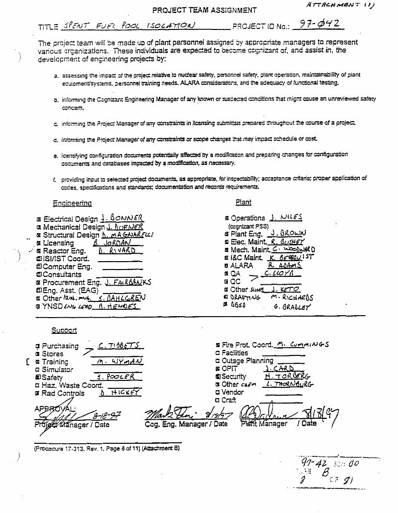
ATTACH MEN 7 I I ) PROJECT TEAM ASSIGXMENT
- I ne prc,iec: :earn will Se made up of plant penonnei assigned by a~prccriate managers to represent varicus zr~anizaticns. Tnese individuals are expected to b e c x e cqnizant of, and assist in, the
1 develocnent of e n y e s i n g p m j e e by:
a. assessing Lye impac: ~f !be Frnjedreiaiive to nueear &Cy. pencnne! safe?/. ;larnoperaticn, maintainability of plant micmentfsys:ems. tencnnd training needs. ALARA unsideradcns, and the adequacl of funticnal testing.
b. infcm~ng me C~qnuanr Eqglneenng Manager of any known or arszeced cndbcns aat migm cause an unrevlewed safeCy cncem.
c. infc-ing 3 e ?rcjes Managerof any unmaints in licensing submit& pregared 3mughcut h e c u n e of a p m j e
a. inicrning me P r c j e ~ Manag~OfaRy unsbaints orsupe danges 3at may impae sffledule or ust
e. icenaving anfirgadon dowments potentialty affecM by a mcddicancn and preparing eanqes for umlguraticn dcwrnents and databases impacted by a modaiCatim, as nec?sSW.
f. prcviding input :o seleded pmjed documents, as appropriate, for ins@abilility: a e p t a n e citeria' pmper application of cces, speCncadcns and standard% documenfatfan and ffi& rguirements.
Encineorina
a Eecttcal Design 1. Oo~aEk IZ Mechanical Design J. h r > ~ t J f l
.. B Structural Design b. MA G ~ h i i € W , m Licensing lo RnAd
- ~4 Reactor Eng. R j v A R o ) ISlflSTCood. a
Computer Eng. Consultants
o Procxement Eng. J. f h ~ RBAUKS Eng. Ass:. (E4G)
E Other h l m 6 . 3 . OA~Ldkt 'hl r8 YNSDmk Lk70 6. r \ E W K I
q Purcnasing m Ere Prot Cocrd. f i - C u r l u ~ u G S 6 Stores o Faciities
[ 8 Trainmg M . U Y n A U 0 Outage Planning 0 Sirnulatcr sp OPlT
Safety 5 . PWLPR Secdrity n Haz. Waste Coord. a Other cur* f . 'ntcad&R~r @ Rad Cantrois b rCrCu&Y o Vendor
0 c m A
Cog. Eng. Manager I Date
(Prccecure 17-313. Rev. 1. Page a of 11) (Attx!Iment 6) J

N0.8.5 6, . I 4 a
Rev. No. 1 A T j - 4 ~ ~ ~ L f N T ; Page 4 o i 10
ATTACHMENT A Continued (Page 1 of 2)
MAINE YANKEE PROJECT AUTHORIZATION REQUEST
A. PAR No: 97-062 Capital: IE] Deferred: 0
- O&M: Insurance Claim: i_'
B. TITLE: SPENT FUEL POOL ISOLATION
C. BRIEF DESCRIPTION: Tne'spent fuel pool will be isolated from the rest o i the plant. This will i n c ! ~ but not limited to the following: spent fuel pool cooling, filtration, chemical addition, fuel building HV control room relocation, secunty perimeter reductions, fire protection isolation, and the assock electrical changes required to isolate the fuel building from the remainder of the plant.
D. PROJECT DESCRlPTlONlDlSCUSSlONIJUSTIFICATION: (Information from Estimator's wor!aheer Par1 See attached cost beaefic analysis for jusrificarion.
TOTAL ESTIMATE: S1.353.6 1 F i p e Detnn~nrl on EIIIMCO~': '.S'~:rLhe:: ?..
E. MILESTONE SCHEDULE: (MONTHNEAR) F. ROUTING FOR APPROV) ' PLANNlNGiPRELlMlNARY ENGINEERING PHASE:
ESTIMATED START DATE: , 0811 3/97 ESTIMATED FINISH DATE: 1211 5/97
CONSTRUCTlONllNSTALLATlON PHASE:
ESTIMATED STAXT DATE: ESTIMATED FINISH DATE:
ACCEPTANCE PHASE:
START DATE: FINISH DATE:
. i $4 - 1
Department 8Manaser
Plant Manager (For Plant Depts.:
Cognizant VP
(Funding Review)
VP Fin. 8 Adm. (All Capital PAR3 > S50.0001
President (OBM PAR;- > S250.000 and all Capital 7Ai7'sl
Accounting (All PAR'S;
No.8.5 Rev. No. 1 Page 5 of 10
ATiACI-1MENT A Continued (Page 2 of 2)
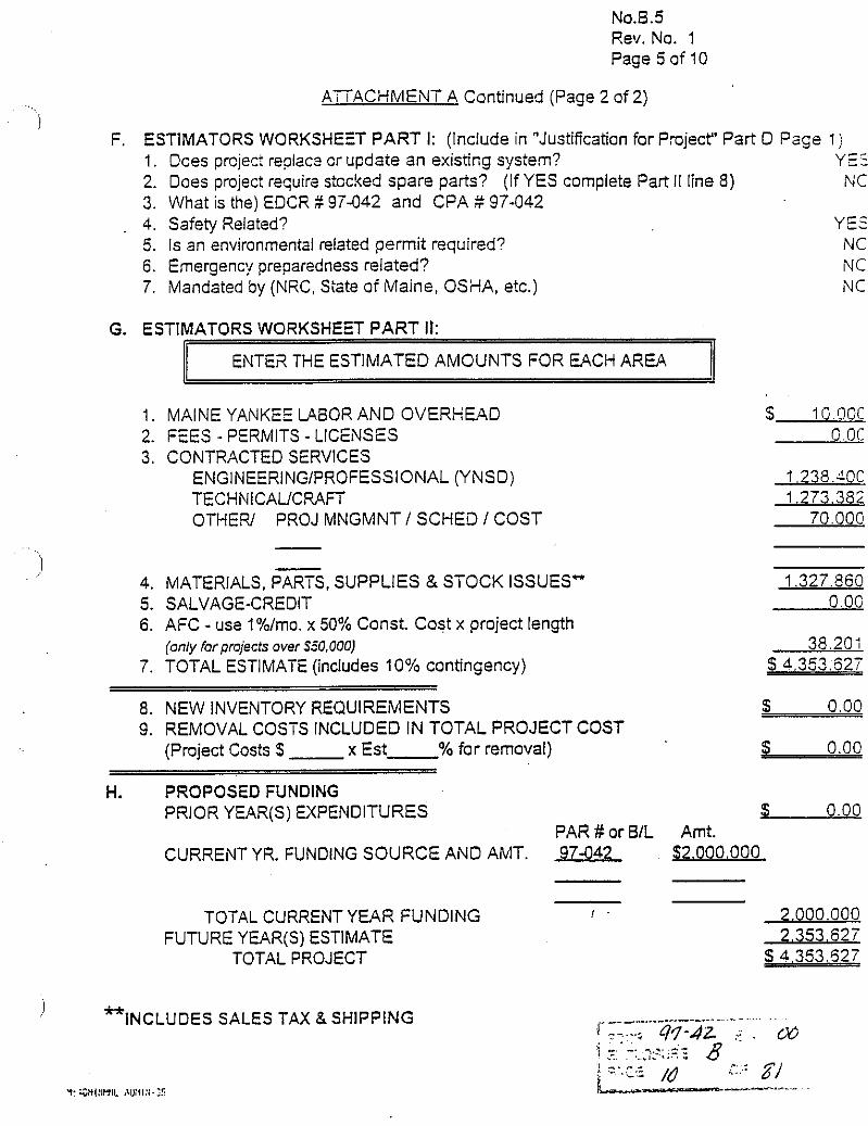
F. ESTIMATORS WORKSHEET PART I: (Include in "Justification for PmjecY Part D P a ~ e 1 ) 1. Does prcject reglac2 cr update an existing system? Y25 2. Does project require stocked spare parts? (If YES complete Part II line 8) N C 3. What is the) EDCR $97-042 and CPA S 97-042
. 4. Safety Related? YE: 5. Is an environmenial related permit required? N C 6. Emergency preparedness related? N C 7. Mandated by (NRC, Siate of Maine, OSHA, etc.) N C
G. ESTIMATORS WORKSHEET PART It:
ENTE2 THE ESTIMATED AMOUNTS FOR EACH AREA
1. MAINE YANKEE LAaOR AND OVERHEAD 2. FEES - PERMITS - LICENSES 3. CONTRACTED SERVICES
ENGINEERINGIPROFESSIONAL (YNSD) TECHNICAUCRAFT OTHE,V PROJ MNGMNT / SCHED I COST
- 4. MATERIALS. PARTS. SUPPLIES & STOCK ISSUES" 5. SALVAGE-CREDIT 6. AFC - use l%/mo. x 50% Const. Cost x project length
(only for projects over S50.000) 7. TOTAL ESTIMATE (includes 10% contingency)
8. NEW INVENTORY REQUIREMENTS 9. REMOVAL COSTS INCLUDED IN TOTAL PROJECT COST
(Project Costs S x Est- % for removal)
H. PROPOSED FUNDING PRIOR YEAR(S) EXPENDITURES
PAR # or BIL CURRENT YR. FUNDING SOURCE AND AMT. 97642
TOTAL CURRENT YEAR FUNDING , FUTURE YEAR(S) ESTIMATE
TOTAL PROJECT
i *-*. INCLUDES SALES TAX &SHIPPING
Y ~ W I , Y l L ,!u;llY.?
$ 0.00 Amt.
$2.000.000

SPENT FUEL POOL ISOLATION COST BESEFIT ANALYSIS
It has been proposed :hat the Spent Fuel Pool and supponing systems be isolated from the remainder of rhe plant in order to bener support plant decommissioning activities. Currently the Spent Fuel Pool is supponed by numerous systems and components not located within the Spent Fuel Pool Building. This analysis will examine the potential cost benefit ofcreating a Spent Fuel Pool "isiand". while alsa considering potential aflecrs on penonne! and ?lam safcy.
Ele latest "Decommissioning Cost .Analysis for the Maine Yankee Atomic Power Station", prepared by TLG Scrcices. assumed thar a Spent Fuel Pool island would be created to suppon decommissioning activities. This study is being used in preparation for the upcoming FERC rate case.
Snis cost benefit analysis will be valid regardless of whetl~er rhe Maine Yankee plant is decommissioned by ;Chine Yankee personnel. a Decommissioning Operaring Company (DOC), or some combination thereof.
The ultimate purpose of this project is to allow for the decommissioning of the Maine Yankee plant, unencumbered by the presence of operating. pressurized. or energized equipment The Spent Fuel Posl isolation project will accomplish the majority of work required to reach this objective: however, additional projects will be required in order for the plant to reach a h l ly "deenergized" state.
T'iie removal cost of operating equipment, that will be abandoned as a result of this project, has not been included in this analysis. This is a reasonable assumption, as MaineYankee is currently decommissioning, and removal cost for all equipment, currentiy installed. is included under decommissioning costs. The removal and disposal cost of any nerv equipment installed by this project are included in this analysis.
The majority of the equipment insxlled by this project will be installed in non- contaminated areas, and is assumed to be Free released as part of future dismantlement. New equipment that is assumed to become contaminated, inclides HVAC motors. the unit hezten closest to the pool, the Spent Fuel Pool tiitration and chemical addition skids, as well as a new hel pool skimmer system. It is assumed that these waste will be compacted as necessary to obtain at l e s t a 60.1 lbs'fr' density, and will be disposed of at the current cost ofS5.50 / Ib.
The man-rem estimate found in the current TLG decommissioning cost srudy represents dose'rec-ived by personnel directly involved in the decontamination and dismantlement
ac:ivities. as we!l as associated health physics personne!. As decontamination and disnantlement activity durations are reduce&. a corresponding reduczion in dose is recogized. Tne dose savings used in this analysis rearesenn the diKerenc2 beween the man-rem e s i L mate found in the T i G cos: study and that found in the Generic Environmental Impac: Srudy. This is roughly half oi the dose savinss calculatei using expeczed reductions in decontamination and dismantlement activity durations. It is asiuned that decon activities would be undertaken, to the extent necessr!. to remain under the man-re3 estimate found in the GEIS. This assumption is consistent with the PSDAR. The cost of additional "loop decon" ac5vities is not considered in this analysis.
It is assumed that the m o u n t of mateials required to be stocked is negligible, when compared to the amount of stock items required currently for Spent Fuel Pool support systems. Any spare parrs required to be stocked. that a~ not currently stocked. have been included in the project estimate.
'vthile substantial changes to tax and insurance rates are expected due to pimt decommissioning, these are not a direct re~ul i of Spent Fue! Pool isolation, and nil1 not be considered in this analysis.
The schedule for Spent Fuel Pool isolation is attached. As a summation. the EDCR .
should be complete by 1/98. mith installation and testing being completed by G9S. These dates support the current decommissioning schedule found in the PSDAR.
The consrmction of a Independent Spent Fuel Storage Installation is assumed to be completed in a time h e which would permit the spent fuel to be transferred out of the Spent Fuel Pool by June of 2003. This is consisrent with the assumptions made in the TLG cos: s ~ d y .
l 3 e cash flow graphics are attached for the Spent Fuel Pool isolation project. The current c u h flow projections estimate that approximately nvo million dollars will be spent in 1997, with the remaining 2.35 million dollars being spent in 1998.
The isolation of the spent fuel pool is not required by reglation. and no regulatory action would be expec:ed if the fuel pool island would not be created.
ASSESSMENT OF X E D :
This project is not required to me-: regulatory requirements, and thus is not categorized as ma mi at on^.
Additionally, it is not required for the safe operation of the plant (or Spent Fuel Pool and associated systems), and would not be viewed as a critical project. hllile the creation o f a Spent Fue! Pool island may decrease the probability of damage to fuel pool cooling and auxiliary systems during the demolition of the plant, it is not essential to the safe operation of these systems. .. -- - --.-.-...--.---..--------.
- -. .- . . . . . .. 9.1- 42 .:.,:< . . . . B . . . - .. . . . . . 12 El
-. >...--...-, .
Tne Spent Fuel Pool Isolation project is categorized as imporranl. Tnis c!assification includes projec:~ which are economically justifiable, bxed upon the resulting cost savings.
ALTERUXTIVES:
1) Isolation of the Spent Fcel Pool island in order to allow for the decommissioning of the blaine Yankee plant. unencmbered by the presence of operating pressurized. or ene:,nized equipment. This alternative is reflected in the lates~ "Decommissioning Cost .balysis for the Maine Yankee .Atomic Power Station", as prepared by TLG S e , ~ i c t s .
2 ) L't~lize the current jystems to maintain the Spent Fuel Pool and associated auxiliaries in their current configuration. Demolition activities would be "engineered" so as not to damage active systems required for spent Fuel pool cooling. .4dditional activities result~ng From this approach would include: heavy load drop analysis'. de:e,ninations of electrical equipment. additional component danger tagging by operations. labeling of systems approved for demolition to allow crafr identification. etc. .in overall increase in the decommissioning cost estimate would be expec:ed if this alternative were st!ecred.
3) The third alternative considered was to implement some poriion of the proposed projec:. It has been dem.mined that the benefits of ensuring that the plant is in a deenergized state can not be h l ly realized until project completion. Thus. by delaying, or cancelin%, someporrion of the proposed project the return on investmenr would not be realized.
The proposed projec: consolidates systems and equipment important to maintaining the spent he1 in a safe manner, and in accordance with plant technical specifications. These systems would be isolated Evrn the remainder of the site, which will become, effectively, a demohion site. This will protect worken kom energized systems, and critical systems From demolition activities. CreatiqaSpent Fuel Pool island will inherently increase safety. both for the worker and the plant.
The creation of a Spent Fuel Pool island also allows decommissioning activities to be undertaken in a much more tfficient and expedient manner. This allows the entire decommissioning process to be completed in a shorter time h m e . The cost benefit ofbeing "green in seven" as Opposed to being "green in eight or nine" is not limited to the quantirarive benefits found in this analysis. The consolidation of decommissioning activities within a shorter time frame, allows the truncation of expenditures that represent "suppori"activities earlier, thus reducing the overall decommissioning cost. This reduction of cost is not being quantified within this analysis.
In addition, the Spent Fuel Pool island approach is essential to the successful completion of our mission to safely and cost effectively decommission the Maine Yankez plant, while beinz
responsible to our community and our employees.
The results oithis cost benefit malysis s u p p o ~ the estimated expenditure of 4.35 million dollars in order to isolate the spent fuel pool. The pay back period is approximately bvo years with the oven11 cost benefit of over nineteen million dollars. net present value. through the end of decommissioning In addition, the implementation of this project will substantially enhance the safety of the work place, throughout the decommissioning process.

CASH FLOW I\/LiTRI,Y
CJSG Initid Invesunent 2.000.000i 2.353.627 01 0 0 0 4.35;. 52- ,Additional Ware Disposal 0: 0 0: 0 0 22.338. -- Y .- y,~ CJSI Additional Removal Cosc 0. 0 0: 0 0 150.000 1511.0CC Total Yominal Costs 2.000.000 2.353.62: Om 0 0 173.338, 4.525.965 P:eser.t Vdue 2.000.000 2.lj9.66i 0. 0 0 107.629 42i-,291:
Bene:',~ Impac: on Operadons 0: 110.000 60.000 60.000 I l O . O G C , Impac: on Maintenance 0 160.000 240.000 240.000 240.000 L60.000 1.0'0.OOCi Impact on Security 0 240.000 360.000i 360.000 360.000 240.000 l.56fi.0001 Impact on Engineering i 0 1.320.000 l.320.000: 1.320.000. 1.320.000 1.320.000: 6.600.000I Impx: on Personnel Dose i 0: 94 .64 L89.380 189.230 189.280 182.520. 8~5.0CCi Impact on Demolidon ! 0; 2.350.000 4.700.000! 4.700.000: 4.700.000 4.350.000: 21.000.fiGO! .kcivities ! Total Nominal Benefits 0: 4.234.640 6.869.280: 6.369.280 6.809.180 6.452.520 3i.2SS.OOCl Present Value 0' 3,595,127 5.677.09l. 5,160.993. 4.650.830 4.006.507 Z.590.547i
Total Nominal Impact . (?.OOO.OOO)! 1.931.013: 6.569.180! 6.869.290 6.309.180 6.179.182 26.i53.03Si
Cumulative Nominal Impact i (2.000.000) (68.987); 6.3002931 13.669.533 t0.47S.S5j 36.758.033 1 I
Total [mpact (NPV) i (2.000,000)! 1.755.466 5.677.091; 5.160.992 4.630.830 3.598.5781 19.1G.257 Cumulative Impact (NPV i (2.000.000Y 5 3 5.432557 10.5933~9 l5.344.379 L9.14j.257 I
I

CASH FLOW DETAILS
DESCRIPTION
costs
Initial Investment Scent 5 e I Pool Isolation 4353627 dollars
TOTAL COST 4353627'doIlars
- ~ -
Additional \Naste Disposal Cost HVAC motor weight 453 ibs
HVAC unit heater wight 200 lbs
.SF= ffltrationlchem additionlskimmer weisht 3550 lbs
TOTAL we~cht 4205 lbs
D~soosal cost per pound 5.55
TOTAL COST 23337.75 dollars
Additional Removal Cost :Mac?ower 10 people
!Duration in weeks 15'weeks
iHours per week A0 hourslwesk
iCos: per hour 25~doilan:hr !
!TOTAL COST 150000 dollars I . .
Benefits
Impact on Operations 'Manpower 1 *people
iDuration in yean 2'years
lHours per year 2000~hourslyr
!cost per hour 6O:dollanihr I
!TOTAL COST 240000 dollars I I
Impact on Maintenance IManoower 2lpeoole :Duration in months 52lmonths
i Hours per month 166.67'hourslrnonlh
ICOS: per hour 60idollardhr ! I
t !TOTAL COST 1040020.8~dollars
imoac: on Security ~blanoower in peoole per shiit 3:peoole ---.. . . ...
,. -..A,- . ! -. . . 07-42 : . Ud : :=.:+ - ..,. -.. L. :-LL:C,;.::; 6 2 .= : . .- -- /& . XI'
i ... .-.. . . . . .
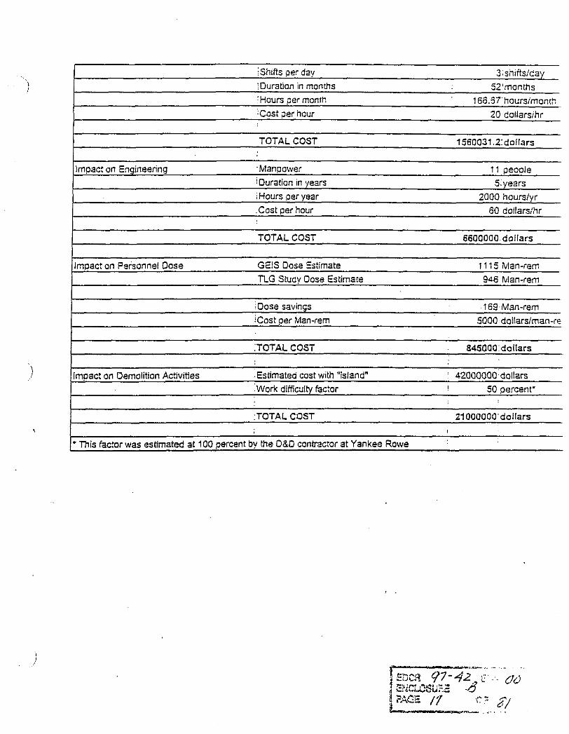
Shlfts per day 3:shlits:day ;Duration in months 52'months !Hours ger month 16C.5'i'hoursimonr~ Cos: 3er hcur 20 collars;hr
TOTAL COST 1560031.2:dollars
Impact on Engineering .Manpower 11 peoole ~ :Hours per year ZOO0 hoursiyr
.Cost per hour 60 do1lars:hr
TOTAL COST 6600000 dollars
Impact on Personnel Dose GE!S Dose Estimate 1 1 15 (Man-ram TLG Study Dose Es:ima!e $46 Man-rem
Dose savin~s 1 6 Man-rem
'Cost per Man-rem 5000 dollarsiman-re
:TOTAL COST 845000 dollars
Irnpac: on Demolition Activities .Estimated cost with "islznd" : 42000000dollan .Work difric~lty fac:or ! 50 percent'
:TOTAL COST 21000000'dollars
- This factor was estimated at 100 percent by the D&O contrac:or at Yankee Rowe

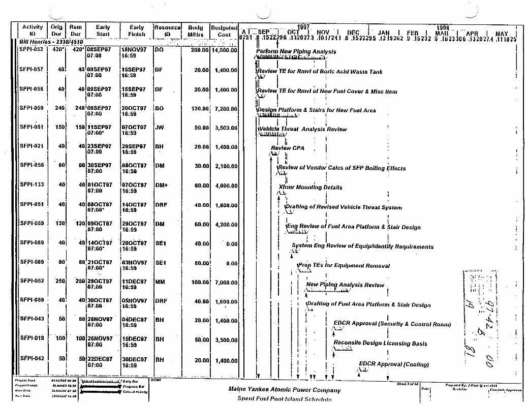
Acllvlty I ID BIN t ler~r l SFPI-052
SFPI-057
SFPI-058
SFPI-059
SFPI-051
SFPI-021
SFPI-056
SFPI-133
SFPI-051
SFPI-059
SFPI-089
SFPI-089
SFPI-052
SFPI-059
SFPI-043
SFPI-019
SFPI-042
-
~rforni New Plplna Analysis . .. . . . * -,
I ' I !evlew TE for Rn~vl of Boric Acid Wasle Tank iz 1
1 5 ~ ~ ~ 9 7 IDF 16:59
I5SEP97 DF 16:59
ZOOCT87 160 16.59
070CT97 JW 1659
Z9SEPB7 BH 1659
OBOCT07 DM 1659
070CT97 DM+ 1659
140CTB7 DRF 18:59
28OCTB7 DM 16:59
2OOCTB7 SEl 16:59
03NOV97 SEl 1659
11DEC97 MM 16x59
05NOV97 DRF 16:59
04DECB7 BH 16:59
15DECB7 BH 16:59
30DEC97 BH 16:59
I 1 !evlew TE for Rnivl of New Fuel Cover 8 Mlsc lleni ii I . !
!
n 8 Slalrs for New Firel Area , I
I I i Jel~lcle . -. Tl~real Analysis Review -1
I 1. I I I1
review CPA , I ' il
I 1; ~Revlew of ~ e n d o i Calcs of SFP B o l l l n ~ &CIS I LLS !
i
I t &rafIlng of Revised Vel~lcle Threat S;slenl i .U.' I
I I i \Ella Revlew of Ftrel Aroa Plalforrr~ 8 Slalr Dosign ,.-
i . I 1 ' !
) System En0 Review of EqrrlpNdenlMy Raq~rlren~ents .:a: I I
Prep TEs for Eq~r lp~ i~en t Removal I i .LI I I . I
I ! j New ., p+inl! ., Analysls . .. , Revlew I I * , I -
I I
I 1I)raftino of Fuul Area Plallorru 8 Slalr Dunloo . I . ! ~,* i I EDCR Approval (Seqrrlly 1 8 Conlrol Roonl)
! I Reconslle Doslan Llcenslng Basls
I . I


a:", t., C 0 = ." 0 x z g z x - - Z Z E Z Z 7 , .- - '7 - i
'7 C '7 7 '7 - 7 - - '7 7 C '7 '7 '7 '7 . - 5 " L a L L ' " L i $ $ $ Z . i ; : . . , 2 2 L L u. . : = 2 < - w a w m a a a a m a u 1 a a w m U) $ 3 : :
o < . a $

SFPI-094 40 OBOCTB7 140CTS7 DRF 1 1 '1 1 0 7 0 I : I 1 40.00 I 1.600.00 I I 1 - . . --..I i . . . - 1 ... : ............... , . . . ............. . . . . . . . . . . . . . Mlke Mallow - 2142 .: i l
. . . ,. SFPI-037. ; 200,' ...-..... .- ......................
200' 220CT87 2 5 ~ 0 ~ ~ 7 : ! I ~ : O o P6;!i9 I .. ! . . . . . . . .
Bob Jordan - 4243 . . . S P l - 0 1 9 1 6 5 0 ~ 2 ~ ' a j
1659 1 I . . . . . . I 1 . . . I . . . . . . . . , . . . . Slan Urbanowskl- 2380 ., .
Ep--- ... (
8.1 ,E ,15.222$6.
i I
. i i I
l f l ly Fuel Pool I LJZa:
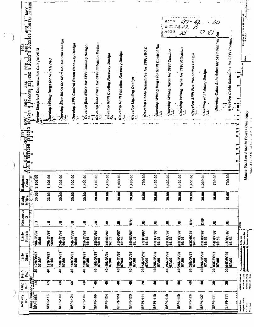
C l e c Drafflno o f SFPI coo11110 Deslan . \ ; !I: i . \Elec DraHlnq of SFPI Flllrallon Daslan ,.: ! A:
i ~ c ~ : $ + f y d a n t Ravlew (lnnslr. d Controls)
I .,
i -: ! EDCR ~ p p r o v a l (Elacfrlcal) . .u.;
11 I A
II : I I i i i vlda CPA l n p ~ r l - Seclrrily d Con/rol Roo111
! .!,
Weslan Fuel Pool lsland Seclrrlly S y s l e r ~ ~ .Wi'i'
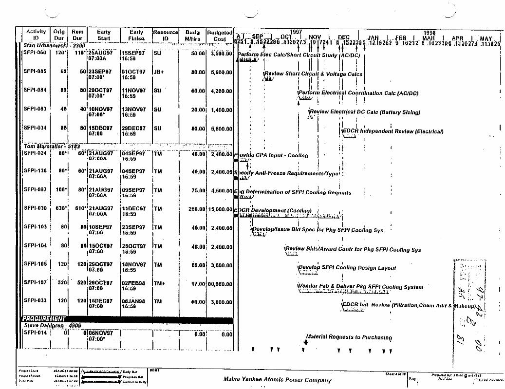
keview BidslAward Canlr for Pkg SFPI CooNng Sys U i
develop SFPl Cooling Design Layor11 . L A
! $'!"dam,pb.+ D+: Pkg SFPl Coollng Syslenr - . , ,-,-am:
~ D C R 1t;d. ~ e v l o ~ ( F i l l r a l l o n . ~ l ~ r r l ~ Add h . .,. . . \.irrLLi
Malerlal Reqlreols lo P~~rc l~as lnq + 1 T 1 1 1 T 1 1 1
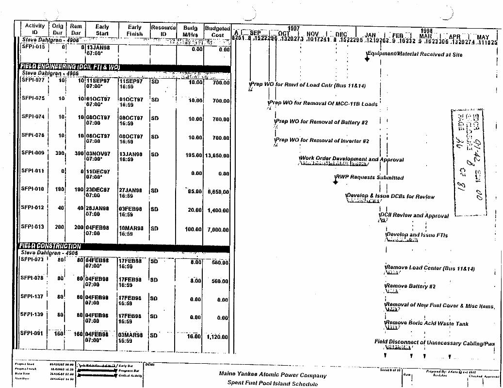
I SFPI-074 I
I
Slave Dahlg, SFPI-073 1 -
i SFPI-078 :
SFPI-137 1 I
SFPI-139 1 I
s F P w i t 1- .
, 0
. . I lPrW WO lor Rn~vl of Load Cnlr (81:s 11al~j
I I i
ti: 2 2
Q. for Revlaw C
I @emoval olNe!v Fuel Cover a hilsc ltarns, .\Wi;L?

1 DOSE ESmUTE FOR CPX 97.042 1 Work :ciinty/Locxion
SFP Cooling
FB 5. 21' ~Twk Bay .h) & in Yard I 345i 0.2 I 0.890 I I
Estimated Man-Hrs
Est Lev& (mBfHR)
F3 2. ?!' (Ti~ck Bay .area) md Roof
Ion Exhaage Skid
E n Erposurr $vIanRemj
m.4c
In >SF? (Work from E. C) 1 427
I TaT.L I 12473 I A271 I 1. Assumes bar only 33% of 13,G7 total elrctiul work hours mll k on the hotside.
FB 5 .21 ' (Tuck Bay . ba r acd Raof
862
0.4 I 0.171
Security
I 0.2 I 0.172
P r i r m ~ >lake-ap
FBP.43 El. 21' $. ?6'
FEl Tipe Tpael
.' 1048
rn El. ?c' 1 692
0.i I 0.105
0.J 1 0.277
950 0.2 , I 0.190
-- 3 0 5.0 1 1.600

I SFP Cooling I
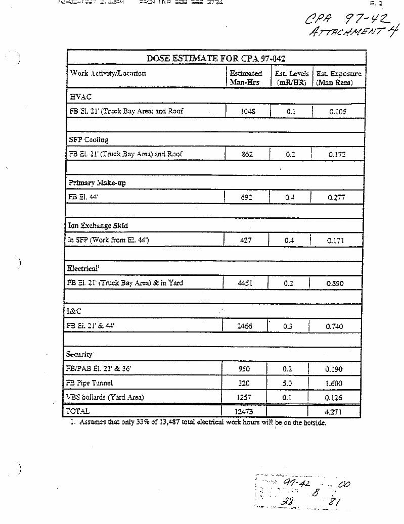
DOSE ESTIMATE FOR CPA 97-042
Work Activity/Location
FB El. 21' (Truck Bay Area) and Roof
( Ion Exchange Skid I
Estimated Man-Hrs
Primary Make-up
1 In SFP (Work firom EL 44') ( 427 1 0.4 1 0.171 1
W A C
862
FB El. 44'
Est Levels (IuWHR)
FB El. 21' (Truck Bay Area) and Roof
- - -
0.2 0.172
I FB El. 21' & 44' 1 2466 1 0.3 1 0.740 1
Est Exposure (Man Rem)
692
- -
Elecrrical'
1 security I
1048
FB El. 2 1' (Truck Bay Area) & in Yard
FBtP.48 El. 21' & 36' 1 950 1 0.2 1 0.190 1
0.4
0.1
0.277
445 1
0.105
FB Pipe Tunnel
VBS bollarcis (Yard Area)
TOTAL
0.2 0.890
1. Assumes that only 33% of 13,487 total electrical work hours will be on the hotside.
320
1257
12473
-- -
5.0
, . 0.1
1.600
0.126
4.27 1

CPA 9742 Attachment A.l
SFP ISLAND COOLING SYSTEM DESCRIPTION
I. GENERAL
The Spent Fuel Pool Island (SFPI) cooling system removes the decay heat from the spent fuel stored in the fuel pool by circulating the borated pool water through a heat exchanger to a secondary loop where fan coils disperse the heat to the outside atmosphere. The system maintains the temperature of the Spent Fuel Pool (SFP) temperature within acceptable limits.
II. SYSTEM DESIGN PARAMETERS
A. The SFPl cooling system is designed to meet the following performance criteria:
1. Maintain the SFP bulk water temperature less than or equal to 80°F with an outside air temperature 68°F (FSAR 2.2.2 highest mean temperature per year) with a duty of 4.37 Million BTUs per hour (Memo RPJ-97-80).
2. Maintain the SFP bulk water temperature less than or equal to 120°F with an outside air temperature of 87°F (ASHRAE 1% summer value for Portland, ME) with a duty of 3.21 million BTUs per hour (Memo RPJ-97-80).
3. Normally maintain the SFP bulk temperature between 75'F and 85'F year round.
4. Provide adequate surge capacity for cooling system temperature variations.
5. Provide redundant (Installed spares) cooling pumps for maintenance activities.
6. The SFP secondary cooling system will be protected from freezing to -9°F (slightly below the ASHRAE 1% winter value for Portland, Me (-6°F)) by the addition of inhibited ethylene glycol to give a 40%(by volume) solution. This solution will provide burst protection to below -60°F.
7. Cooling system able to recover from an incident of a boiling pool where the water in the primary and secondary system may reach 212°F..
8. Maintain SFP bulk temperature above 68°F. This is the lower temperature assumed for the criticality analysis. Note: discussions with YNSD (R. Cacdapouti) confirmed that temperatures as low as 40°F could be shown to be acceptable, however, a formal analysis has not been performed at this time
9. The secondary system is protected from overpressure by the use of a surge tank and a thermal relief valve on the E-25 heat exchanger.
10. Normal make up of coolant is provided by the PWST. This will maintain pool level and secondary side inventory as needed.
Page 1 of 10
SFP ISLAND COOLING SYSTEM DESCRIPTION
CPA 9 7 4 2 Attachment A.1
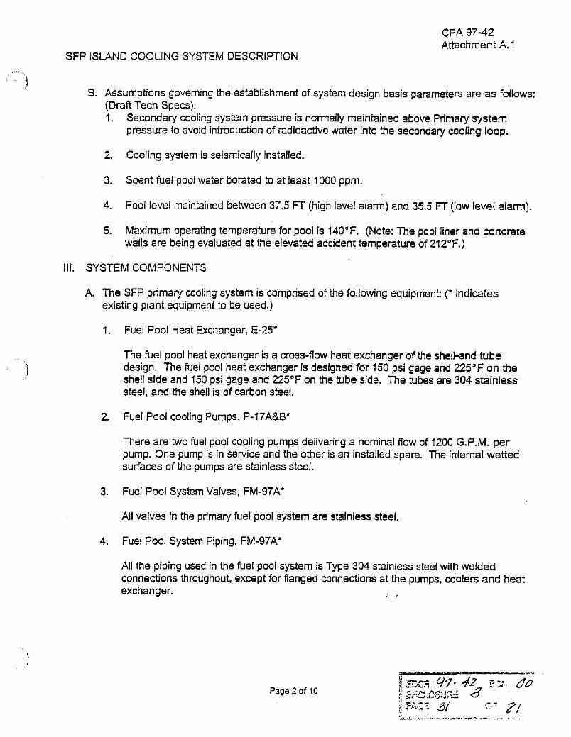
8. Assumptions governing the establishment of system design basis parameters are as follows: (Draft Tech Specs). 1. Secondary cooling system pressure is normally maintained above Primary system
pressure to avoid introduction of radioactive water into the secondary cooling loop.
2. Cooling system is seismically installed.
3. Spent fuel pooi water borated to at least 1000 ppm.
4. Pool level maintained between 37.5 FT (high level alarm) and 35.5 FT (low level aiam~).
5. Maximum operating temperature for pool is 140°F. (Note: The pool liner and concrete walls are being evaluated at the elevated accident temperature of 212°F.)
Ill. SYSTEM COMPONENTS
A. The SFP primary cooling system is comprised of the following equipment: (* Indicates existing plant equipment to be used.)
1 Fuel Pool Heat Exchanger, E-25"
The fuel pool heat exchanger is a cross-flow heat exchanger of the shell-and tube design. The fuel pool heat exchanger is designed for 150 psi gage and 225'F on the shell side and 150 psi gage and 225°F on the tube side. The tubes are 304 stainless steel, and the shell is of carbon steel.
2. Fuel Pool cooling Pumps, P-17A&W
There are two fuel pool cooling pumps delivering a nominal flow of 1200 G.P.M. per pump. One pump is in service and the other is an installed spare. The internal wetted surfaces of the pumps are stainless steel.
3. Fuel Pool System Valves, FM-97A'
All valves in the primary fuel pool system are stainless steel.
4. Fuel Pool System Piping, FM-97A'
All the piping used in the fuel pool system is Type 304 stainless steel with welded connections throughout, except for flanged connections at the pumps, coolers and heat exchanger. , .
Page 2 of l a

CPA 97-42 Attachment A.l
SFP ISLAND COOLING SYSTEM DESCRIPTION
5. Instrumentation
The fuel pool has level and temperature alarms which provide high and low-level alarms and a highllow temperature alarm in the new control mom. There is a pressure gage on the discharge of each pump. The fuel pool heat exchanger has temperature indicators on the fuel pool cooling inlet and outlet lines. More details of the overall l&C design is provided in Attachment A.6.
6. Water Chemistry
The fuel pool is demineralized water !with boron added to greater than 1000 ppm.
7. Code Requirements
The Fuel Pool Heat exchanger was designed and built to: Tube side ASME Section Ill Class C (Paragraph UW-2(a) of Section Vlll applies). Shell side ASME Section V111. The fuel pool piping was designed to ANSI 631.1-1967.
6. The Spent Fuel Pool System Secondary System is composed of the following equipment
1. Water-to-Air Coolers
The multiple independently fan-cooled assemblies are of the finned coil type. Water mixed with ethylene glycol is in the tube side and air is blown across the coil to remove heat. The units are designed to 300 psig and 350'F. The normal operaEng parameters are anticipated to be 70 psig and 75'F. The tubes are stainless steel and the fins are aluminum.
2. Secondary Cooling Pumps
There are two secondary cooling pumps delivering a nominal flow of 1000 gallons per minute per pump. One pump is in service and the other is an instailed spare. The Internal wetted surfaces are stainless steel.
3. SurgeTank
The surge tank is sized to accommodate fluid expansion and contraction resulting from temperature variations in the secondary cooling loop. The tank is made from stainless steel and located on the pump skid.
4. Air Separator
The air separator, which is located on the pump skid, mechanically removes entrained air in the secondary coolant.
Page 3 o i 10

CPA 9742 Attachment A.l
SFP ISLAND COCLING SYSTEM DESCRIPTION
5. Secondary System Valves
All valves in the secondary system are stainless steel.
6. Secondary System Piping
All the piping used in the secondary system is Type 304 stainless s:eel, except for flexible steel guarded hoses at equipment connections
7. Instrumentation
There is a pressure gage on the discharge of each pump. The seccndary system has temperature indicators on the inlet and outlet (which also indicate in the new control mom) of the fuel pool heat exchanger. The primary and secondary loops have flow indicators that indicate total system flows. (See section IV.7 for more discussion).
8. Water Chemistry
The secondary system is demineralized water with inhibited ethylene glycol added to prevent freezing and corrosion. A program for chemistry monitoring is being developed.
9. Code Requirements
The secondary system piping is designed and built in accordance with the requirements of ANSl 831.1-1980, and Maine Yankee Piping Specification MYS442 Rev. C, Class 152.' The coolen, air separator, and surge tanks are designedlprovided by the vendor. Pressure boundary design will be consistent with commercial industrial consensus standards (i.e. ASME. API, etc.) In accordance with the requirements of ANSl 831.1 and subject to Maine Yankee review and approval.
IV. SYSTEM ARWNGEMENT
1. Fuel Pool Cooling Pumps
The fuel pool cooling pumps are arranged in parallel, drawing a suction from the pool discharge line. The pumps then discharge the water to the inlet tube side of the Fuel Pool Heat Exchanger. One pump is normally operating and the other is an installed spare.
2. Fuel Pool Heat Exchanger
The fuel pool heat exchanger transfers heat from the p r i t & y system(poo1 cooling water in the tube side) to the secondary system(water in shell side).
Page 4 of 10

SFP ISLAND COOLING SYSTEM DESCRIPTION
CPA 97-42 Attachment A.l
3. Secondary Side Cooling Pumps
Circulates water from the fuel pool heat exchanger to the water-to-air coolers and back to the shell side of the fuel pool heat exchanger. The pumps are located in the Fuel Building at elevation 21 ft. One pump is normally operating and one is an installed spare
4. Secondary Side Cooling Surge Tank
The secondary side cooling surge tank provides system overpressure protection. volume for expansion and inventory for contraction of the secondary side cooling system during normal and abnormal operating conditions. The surge tank is located on the secondary side cooling pump skid.
5. Water-to-Air Coolers
The water-to-air coolers reject heat from the secondary system into the surrounding atmosphere by the use of finned tubes and forced air. The coolers are located in a diked area north of the current BWST dikes. The cooler fans are staggered to operate as the heat rejection rate changes with air temperature. Flow is provided to all the coolers whether or not the fans are operating. A cooler may be permanently removed from service once the cooling load (spent fuel decay heat) has decreased.
6. Emergency Connections
The currently yellow tagsed hose connections (both fire water and SCCW) to the secondary side of E-25 heat exchanger will be maintained and made permanent as part of this design change. In addition to the existing diesel pump backed fire main connections inside and outside the Fuel Building, an existing fire hydrant adjacent to the fire pump house is connected to the Wiscasset water supply. This provides an additional means of cooling the spent fuel pool heat exchanger in the event normal cooling is interrupted.
V. SYSTEM OPERATlON
1. General
The pumps are provided with local controls. These controls have a 'stop-run" control switch, and running indication lights. One pump on each the primary and secondary cooling loops will initially run continuously year round. As the decay heat of the spent fuel decreases, periodic isolation of the cooling system may be required.
The water-to-air cooler fans are controlled from two temperature indicators on the primary system. Each temperature indicator will control nine fans on three units. This allowsfor the failure or maintenance of one control circuit without system shut down. Normally, the fans will start as the temperature in the system increases and will shut down as the system cools.
Page 5 of 10

SFP ISLAND COOLING SYSTEM DESCRIPTION
CPA 9742 Attachment A.l
If the pool temperature rises above 90°F or falls below 70"F, an alarm is made in the control room.
Manual valves at each cooler will allow balaneng of cooler water flow, and allow the coolers to be removed for maintenance. The a i l s can be drained locally.
In the event that a fuel handling or cask handling accident occurs, the heat load of the system is not effected.
Flanged connections are provided on the heat exchanger cooling (shell) side to allow the alignment of emergency cooling supplies, if nended.
If the running pump trips (primary or secondary) an alarm will annunciate in the new control room.
The secondary coolant is formulated with a corrosion inhibitor. If monitoring indicates the necessity, addition of corrosion inhibitor (dipotassium phosphate) to the secondary coolant can be accomplished using the 'bleed and feed" method. No chemical addition tank or special valving arrangement is required.
2. Summer Operation
During summer operation with day temperatures in the 80s and evening temperatures in the 70s the secondary cooling system fans will cycle with air temperature. The secondary side cycling will affect the bulk pool temperature to some degree, however the mass of the pool acts as a thermal flywheel that will dampen any air side air temperature variations.
As the spent fuel decays, the heat load will decrease. At some point it will be possible to remove coolers from the system without affecting the original cooling margin. These coolers can be bypassed with a pressure reducing bypass to maintain system flow balance.
3. Winter Operation
During winter, most or all of the fans will be in standby and radiant and convective flow will remove heat from the coils.
If necessary because of maintenance, lack of heat load or loss of power, the secondary coolant can be shut down. The coolant is water mixed with ethylene glycol for protection from freezing. , .
Page 6 af 10

SFP ISLAND COOLING SYSTEM DESCRIPTION
CPA 9742 Attachment A. 1
VI. OTHER
The spent fuel island design team was charged with making the spent fuel pool and its auxiliary systems independent from the existing plant systems. The diredive also was to make the systems:
1. Cool the spent fuel pool safely, 2. Lowlno maintenance, 3. Minimal operator Involvement during normal and abnormal conditions. 4. Cost effective.
Various options for cooling the spent fuel pool during decommissioning were examined. The options not chosen and the reasons why are discussed here.
1. Use the Existing System
Currently the Spent Fuel Pool is cooled by circulating the pool water through the Spent Fuel Pool Heat Exchanger where the heat is exchanged to the Primary Component Cooling water, the PCC is circulated through the Service Water Heat Exchangers where the heat is exchanged to Service Water and the SW carries the heat into the bay.
This system could cool the Spent Fuel Pool for the foreseeable future with little modification to the existing hardware. However, the continued use of this system is not proposed for these reasons:
A. Use of seawater requires measures be taken on a periodic basis to clean the intake, pipe and heat exchanger surfaces of the service water system, this is maintenance Intensive.
8. The PCC system Is large and would leave sizable portion of this system intact and pressurized.
C. To operate the SW and PCC systems requires the Circ. Water Pump House, the turbine building, the PA6 and other structures be maintained and heated.
D. Site demolition around these operating systems would be difficult and costly.
2. Install a Smaller System Cooled by Seawater, Firewater or Wiscasset Town Water
This system could be installed but was rejected for the some of the same reasons stated for leaving the Existing Systems, namely:
A. The high maintenance required by using a once through, non chemically controlled water, 1.e.. macro foullng by mussels, seaweed, leaves etc., micro foullng by algae. biological growth, corrosion attack by impurities and biological growth.
8. The Spent Fuel Pool Heat exchanger would require replacement (since cooling is on the shell side which cannot be cleaned) or a loop similar to PCC would be required.
Page 7 of 10
SFP iSL4ND COOLING SYSTEM DESCRIPTION
CPA 97-42 Attachment A.l
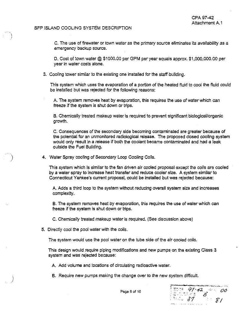
C. The use of firewater or town water as the primary source eliminates its availability as a emergenof backup source.
D. Cost of town water @ $1000.00 per GPM per year equals approx. $1.000,000.00 per year in water costs alone.
3. Cooling tower similar to the existing one installed for the staff building.
This system which uses the evaporation of a portion of the heated fluid to cool the fluid could be installed but was rejected for the foliowing reasons:
A. The system removes heat by evaporation, this requires the use of water which can freeze if the system is shut down or trips.
8. Chemically treated makeup water is required to prevent significant biologicallorganic growth.
C. Consequences of the secondary side becoming contaminated are greater because of the potential for an unmonitored radiological release. The proposed closed cooling system would only result in a release if both the coolant became contaminated and had a leak outside the Fuel Building.
4. Water Spray cooling of Secondary Loop Cooling Coils.
This system which Is similar to the fan driven air cooled proposai except the coils are cooled by a water spray to increase heat transfer and reduce cooler size. A system similar to Connecticut Yankee's current proposai, could be installed but was rejected because:
A. Adds a third loop to the system without reducing overall system size and increases complexity.
0. The system removes heat by evaporation, this requires the use of water which can freeze if the system is shut down or trips.
C. Chemically treated makeup water is required. (See discussion above)
5. Directly cool the pool water with the coiis.
The system would use the pool water on the tube side of the air cooled coiis.
This design would require piping modiflcations and new pumps on the existing Class 3 system and was rejected because:
A. Add volume and locations of circulating radioactive water.
0. Require new pumps making the change over to the new system difficult.
Page 8 of 10

CPA 97-42 Attachment A. 1
SFP ISLAND COOLING SYSTEM DESCRIPTION
C. The circulating fluid could freeze when shut down on loss of power.
D. Consequences of leakage in cooling loop are sever.
E. Coolers may need security protection to prevent sabotageldraining of the SFP.
6. Place the air coils Inside.
This system would place the air cooled coils inside to prevent the water from freezing. Duct work may be required to maneuver the air.
This system was strongly considered but rejected because:
A. The physical size of the coils, 12 by 5 foot print per unit (six total units) and ductwork.
8. The air flow requirements of 50,000 cubic feet per minute per unit, 300,000 CFM total.
C. Duct work, wall penetrations and fans required to move the air are large and expensive.
7. Place the air coils as proposed without Ethylene Glycol
This system is the current proposal without Ethylene Glycol as freeze protection to the secondary cooling water
This proposal was rejected because:
A. Reduced staffing affects the ability to drain the coolers to prevent freezing If the system trips.
0. As heat load reduces, the secondary can be shut down. Without freeze protection, the system must remain running or be drained.
C. Mlsadjustment of valve lineups could cause low/no flow to some areas increasing the danger of freezing.
8. Chiller System
This system involves the use of a chiller (air conditioner) to remove heat. The system was rejected because:
A. High Initial cost. , .
0. Still requires water or air cooled condenser.
C. Complex equipment and controls to maintain.
Page 9 of 10

SFP ISLAND COOLING SYSTEM DESCRIPTION
CPA 9742 Attachment A.l
9. Summary of design choice
The fan cooled closed loop coil system with Ethylene Glycol was chosen because:
A. Slmple system with as few moving parts as practical.
0. Forgiving to operational error and equipment failure.
C. Low maintenance and cost effective.
Page 10 of 10
0 . 4 97-42 Attachment A.2
SFP ISLAND PURIFICATION & MAKE-UP SYSTEMS DESCRIPTION
1. GENERAL
The Spent Fuel Pool (SFP) Island purification system maintains the water chemistry of the SFP within acceptable limits. The SFP makeup water system provides make-up water to the primary and secondary SFP island systems.
II. SYSTEM DESIGN PARAMETERS
A. The SFPl purification system is designed to meet the following performance criteria:
1. The SFP island purification system will maintain the boron concentration in the SFP greater than the 1000 ppm, based on anticipated Technical Specification reductions in boron concentration requirements.
2. The SFP island purification system will maintain the following water chemisw in the SFP in accordance with the revised technical specifications and the IASD:
Boron > 1000 ppm pH 4.5 - 10.5 @ 77°F Chlorides < .I ppm Halogens c 2 5 ppm
5. The SFPI make-up water system is designed to meet the following performance criteria:
I. The maximum boilsff rate of the SFP is assumed to be 60 gpm per the current FSAR. The SFP makeup system will be capable of providing the emergency design basis make-up flow to the SFP by taking suction from the PWST, flre pond, or Wiscasset town water system.
2. The SFP make-up system will provide the normal make-up water to the primary and secondary systems. Make-up requlrernents are estimated to be approximately 100,000 gallons pet year for the primary system, based on an anticipated fuei pool evaporation rate of .2 gpm, and 1000 gallons per year for the secondary system.
ill. SYSTEM COMPONENTS, ARRANGEMENT, AN0 OPEWTION
A. The SFPI purification system, which consists of filtration, ion exchange, surface skimmers, and boron addition, is described below:
I. Filtration
The filtration system will normally be out of service. The system can be started and the appropriate filters valved in as needed. The current puMcation system will be utilized for filtration. Pump P-85 will take suctlon from either the SFP surface skimmers, the SFP pump suctfon, or the SFP heat exchanger discharge. The pump discharge will be routed through FL-2 andlor FL-29 and will return to the spent fuel pool through the spent fuel pool urollng discharge line. The current path to the spent fuei pool ion exchanger (14) will be removed.
Page 1 o f 4 ....... - 7 :...r.. ......<.-...A .---
! ;:. . . . ., .- Oq-42 : .
. . . . , ., j: . . . . . . . . . . :: 48
&
CP.4 97-12 Attachment A 2
SFP ISLAND PURIFICATION & MAKE-CP SYSTEMS DESCRIPTION
2. Boron Addition
The boron addition system wiil be a temporary system that can be connected as needed. The system will consist of a tank, mixer, pump, hoist and funnel. The boron can be hoisted up and dumped into the tank of water through the funnel. The mixer will be used to mix the boric acid into solution. The mixer can then be removed and the pump inserted to pump the solution into the filtration system, (discharge of P-85) and added to the SF?.
A permanent boron addition system is not considered to be a necessary addition since the current boric acid concentration of 1720 ppm is well above the new requirement of 1000 ppm and major reductions in boron concentration are not anticipated.
A permanent boric acid mixing system could be added as a second option. The zinc addition system may be used as a permanent boric acid addition system.
3. Deminerallzation
The ion exchange system wlll operate as necessary to maintain the pool water chemise within acceptable limits (Note: Continuous operation is acceptable but probably not required). An underwater demineralizer system will be used. The system will rest on the bottom of the SFP, initially in the spent fuel cask area. The system can be easily moved to the top of a spent fuel rack or out of the pool completely, if and when a cask is going to be brought into the spent fuel pool. Suction will be taken from one side of the pool and discharge to the opposite end of the pool. All equipment willbe located under water except power cords and a Row-metering device. AII operations wlll be performed from above with the system under water. Resin replacement will be accornpllshed with the use of a pump and sluicing water. Removal of the resin will be performed by taking a suction on the deminerallzer with the pump and replacing the volume with sluicing water provided at the sluicing connection. Resin will be transferred to a suitable High integrity Container (HIC). Resin wiil be added by flooding the clean resin d ~ m with Dl water and pumping the resin slurry into the demineralizer. Replacement of the resin is dependent on water chemistry. It is anticipated that replacement of the resin will be on an Infrequent basis.
An additional option which was considered involved the addition of a skid mounted demineralizer conneeed to the existing purification system and installed In the spare floor plug in the fuel handling building.
4. Elimination of Organics
An evaluation was performed to assess the need to install a treatment system to deal with potential organic growth concems. Since organic growth concems have never been identified a problem in the past, it was decided to monitor the new SFPl and postpone an organic treatment system at this time. (Note: An Ultraviolet (UV) system, similar to the one in use at Yankee Rowe, can be easily installed in the future if any organic growth concems arise.)
Page 2 of 4
CP.4 97-42 Attachment A.2
SFP ISLAND PURIFICATION & MAKE-UP SYSTEMS DESCRIPTION
0. The makeup system for the primary and secondary cooling loops is described below:
1. Primary and Secondary Make-up System
The pnmary system will be used for normal and emergency make-up capabilities. Normal make-up Is supplied from the PWST through Primary Water Pump P-248. whictr will be removed from its current location in the lower level PAB and relocated to elevation 21' in the Fuel Building (FB). Suction and discharge piping at the pump's current location will be blind flanged. This pump wlll take suction from the existlng PWST suction line located outside the FB roil-up door. Pump discharge wlll tie into the fuel pool flltration system at elevation 21'. just downstream of the existlng make-up tie-in. The discharge w~il also be routed to the 3" recirculation line located outside the roll-up door, and to new primary hose connections at elevation 21' and elevation 45'. The pump will have sufficient capab~lity to provide make-up and the maximum boll-off rate of the SFP.
A hose connaction will be provided on the make-up line to the spent fuel pool to provide for make-up from the domestic water and fire protection water systems. The selected hose connectlons are located such that boiling in the pool wlll not signiiicantly llmit accessibility in a steamlfog environment.
Make-up of water to the secondary system will be provided through a hose connection located on the primary make-up pump discharge through a hose to be routed to the secondary system pump suction.
The maintenance of the correct glycol concentration in the secondary system will be performed by periodic sampling of the secondary coolant to determine glycol concentration. Addition of glycol to this system, if required, wlll be performed manually by transfening the required quantity of giycol from drums into the system. No permanent glycol make-up system will be provided.
2. PWST
Tne PWST is a nominal 150,000 gallon tank located in the yard at the north end of the fuel building. This tank wlll be retained to provide a source of Dl water for makeup to the spent fuel pool and to provide other Dl water needs In the fuel building. The current tank heating system using auxiliary steam will be deleted and freeze protection wlll be provided by a new immersion heater in combination with new tank insulation. Existing heat tracing on the lines running to and from the tank will be retained and repowered to prevent freezing of the lines.
Fill of the tank will be accommodated by the addition of an Inlet connection located on the existing pump suction line. This connection will be iocated on the lines outside the fuel building and will be heat traced accordingly. As an alternative, the 611 connection may be located within the fuel building at the 21' elevation. Location of the fill connection on the pump suction line will allow direct fill of the tank through backflow into the tank or by operation of the new primary water make-up pump discharging through the pump recirculation line. (Note: As decommissioning proceeds, the ability to make Dl water wlll eventually be eliminated. At that time, it is envisioned that a Dl truck will simply connect to a

CPA 97-42 Attachment A 2
SFP ISLAND PURmCATION & MAKE-UP SYSTEMS DESCRIPTION
local fire hydrant, create the Dl water and pump it into the PWST.
3. Domestic and Fire Protection Water
Spent Fuel Pool makwp may also be accomplished by providing water from the domestic water system and from the fire protection water system. Water will be provided by hose connection fium a hydrant located near the existing fire pond (Domestic Water) and fium a hydrant located at the west side of the fuel building (Fire Pmtectfon Water). A hose will be muted fmm either hydrant to a hose connection provided on primary water system inside the fuel building.
Page 4 of 4

CPA 97-42 Attachment A.3
, , , . . . , SFP ISLAND VENTILATION SYSTEM DESCRIPTION i
I. GENERAL
The Spent Fuel Pool Island (SFPI) ventilation system maintains the temperature and relative humidity of the Fuel Building (FB) atmosphere within acceptable limits, provides adequate fresh air for the occupants, limits introduc5on of particulate matter, and prevents the forced exhaust of contaminated air in the event of a radiological emergency. Instrumentation installed in the ventilation system provides the capability to monitor andlor sample radioactjvity in the effluent air stream. In addition, this system establishes and maintains an acceptable environment for personnel occupying the control room (located in the security gatehouse), and for the equipment located in this space.
II. SYSTEM DESIGN PARAMETERS
A. The SFPl ventilation system is designed to meet the following performance criteria:
1. Maintain the FB bulk air temperature t 60'F with an outside air temperature of -6°F (ASHRAE 1 % winter value for Podand, ME).
2. Maintain the FB bulk air temperature s 95'F with an outside air temperature of 87°F .. (ASHRAE 1% summer value for Portland, ME).
3. Maintain the temperature in the security gatehouse, including the control room, between 68°F and 75°F.
4. Maintain the relative humidity in the control room between 30% and 70%.
5. Provide adequate fresh air to support continuous occupation by at least ten people in the FB, and ten peopie in the security gatehouse, of which four are in the control room.
6. Provide continuous 60% efficient filtration (per ASHRAE 62-1989) of the supply air to the FB
7. Maintain the FB at a slight negative pressure relative to the outside so that the effluent air can be monitored and sampled for radioactivity.
8. The running exhaust fan, and its associated isolation damper, will automatically trip on a high radiation signal generated either by the FB building area radiation monitor, or by the radiation monitor installed in the FB exhaust duct.
9. In addition to providing a fanldamper trip function, the continuously operating monitor installed in the FB exhaust duct will ensure that any significant release of radioactive noble gases can be identified.
10. Sampling capability for radioactive particulates, noble gases, and tritium in the building effluent air will be provided by means of a sample canister(s) installed in the exhaust
.--.---;,:-I- .r,*r..- --.....-..- _. '! :, , . 97- 4. : flu '' .;. .. .%.,A. .,< <
Page 1 of 10 .. . - . 8 : - 44 . - g/ L -. . . _.. _- ,,-...-. ,.-,- . . .

CPA 97-42 Attachment A.3
SFP ISLAND VENTILATION SYSTEM DESCRIPTION
duct. Access to the sample canister(s) will be provided in the common dudwork at the inlet of the exhaust fans
11. The SFPl ventilation system is not designed to meet any specific relative humidity requirements for the FB, or for the control room. It is expected that FB bulk atmosphere relative humidity will range from approximately 20% (winter) to 80% (summer) depending on the outside air condltions. Condensation on the building inside walls should be prevented by a combination of air heating and exhausting air from above the SFP.
12. Provide personnel exclusion (security) barriers for ductwork which penetrates any FB wall.
8. Assumptions governing the establishment of system design basis parameters are as follows:
1. Under no condltions is carbon filtration of the FB exhaust air required. This assumption is based on a review of FSAR Sections 5.2.4 and 9.8.1, Tech Spec 3.25.C, and discussions with John DiStefano of YNSD Radiological Engineering Group.
2. No ventilation, heating, or cooling is required for the drumming room or the new fuel room.
Ill. SYSTEM COMPONENTS
,? A. The SFPl ventilation system is compnsed of the following equipment:
1. inlet air louvers
The inlet air louvers allow passage of cooling and fresh air into the FB, while excluding rain and snow. Each louver assembly is equipped with a coarse screen to prevent birds from entering the building. They are weather-resistant, passive devices with no moving parts, and are therefore not subject io failure as a result of any forseeable operating condition or event.
2. inlet air dampers
The inlet air dampen, lnstalled downstream of the louvers, are manually operated and are intended to allow closure of the louver openings during winter months. Each parallel blade damper assembly is equipped with an operating handle which can be locked in any position from full closed to full open. I .
3. Inlet air filters
24"x24"x4" disposable air filters, which meet the ASHRAE 60% efficiency criteria for 3 micron particles, are Installed downstream of the inlet air dampers. These filters will
Page 2 of 10

CPA 9 7 4 2 Attachment A.3
SFP ISLAND VENTILATION SYSTEM DESCRIPTION
remove much of the airborne dust which would otherwise enter the FB atmosphere. They are sufficiently rigid to withstand impingement of rain and snow, and their performance characteristlc is such that filter pressure drop is negligible at system design flows. Filters of this type are readily available fmm major suppliers. Local DIP gauges will be instailed to permit easy determination of the onset of filter clogging.
4. Building exhaust fans
Two centrifugal exhaust fans are provided for the SFPI, a minimum flow fan for winter operation, and a high flow fan for summer operation. Tine exhaust fans are mounted on the FB roof, draw air from the exhaust duct located above the SFP, and discharge it to atmosphere. Each fan is driven by a single speed motor. Air flow is directed to the operating fan by two electrically-actuated dampers, one of which isolates flow to the idle fan. The high flow fan draws sufficient ventiiation air through the building to llmit bulk air temperature to the design maximum of 95'F. The low flow fan ensures that during periods of low outside temperature 1) moisture which evaporates from the pool surface will be exhausted to the outdoors, and 2) fresh air requirements are met. A gravity- operated backdraft installed at the outlet of each fan excludes weather from the fan lnternals.
Heavy steel grating is installed in the duct at the FB roof penetration to prevent unauthorized entry into the building via this opening.
5. Heat exchanger room ventilation fan
A platform-mounted centrifugal fan provides unconditioned FB air to the heat exchanger room on elevation 21'.
6. Unit heaters
Electric resistance unit heaters are provided to maintain the FB bulk air temperature at a minimum of 60eF, and to prevent the condensation of moisture on the building interior walls.
7. Radiation monitoring and sampling of effiuent air
Later - The specific monitoring requirements are currently be developed by YNSD.
8. Security gatehouselcontrol room air conditioning system
The security gatehouse air conditioning system conditions the air for this building, Including the SFPl control room. This system consists of a central air handler, three area exhaust fans, and two supplementary roof-mounted heat pump units. The central air handler has mixing, filter, fan, electric heating coil (74 Kw), and refrigerant cooling coil sections. A reciprocating refrigerant compressor, with a roof-mounted air-cooled condenser, supplies the unit's DX cooling coil.

CPA 97-42 Attachment A.3
) . SF? ISLAND VENTILATION SYSTEM DESCRIPTION
IV. SYSTEM ARRANGEMENT
1. lnlet air louvers
The inlet air louvers are installed in the Northwest comer of the West wall at elevation 44' of the FB. The louver sections are sized to provide a negligible pressure drop at design aimow conditions so that excessive negative building pressure cannot occur (the exact size of these devices will be detemined later). The design of the louvers is such that no additional provisions for security barriers are required.
2. lnlet air dampen
The inlet air dampen are attached to the downstream sides of the louvers. They are accessed by the same means as the filters - see discussion on filters below.
3. Inlet air filters
The inlet air filters are housed within filter racks attached to the downstream side of each damper assembly. Front access will be provided to these racks using the existing steel grating walkway so that the filters can be easily changed.
4. Building exhaust fans
These exhaust fans are mounted on the FB roof at roughly the 8% line. In order to minimize work over the SFP, the existing exhaust duct and registers are utilized in the new system. The exhaust duct will be modified so that it no longer enters the PA% but rather continues straight along the FB East wall, and then turns 90" up to a new roof penetration. Once through the penetration, the duct (insulated with rigid fiberglass board) runs strai~ht toward the exhaust fans, then split into two runs, the larger of which connects to the inlet of the high flow fan. In each of the two duct runs there is a manuai balancing damper, and an eiectrically-actuated contml damper. The control damper for the low flow fan automatically opens when this fan runs, and the high fiow fan control damper doses. The opposite alignment takes effect when the high flow fan runs.
5. Heat exchanger mom ventilation fan
This fan is installed on the platform at elevation 36'. It discharges unconditioned building air into existing ductwork which passes through the new fuel mom and down into the heat exchanger rom.
6. Unit heaters
The electric unit heaters are located in the North end of the FB, and just North of the SFP along the West and East walls; the number, size, and exact location of the heaters
-.-~ - Page 4 of 10 .. -.- &-+Q
. . 80
. .. . : 4 7
d s'/

CPA 97-42 Attachment A.3
SFP ISLAND VENTILATION SYSTEM DESCRIPTION
will be determined later. They are installed so that they do not interfere with crane operation or any other activities expected to take place in the FB.
7. Radiation monitoring and sampling of effluent air
Later - The speciflc monitoring requirements are currently be developed by YNSD.
8. Security gatehouse/control room air conditioning system
This system is unchanged from the arrangement shown on current plant drawings (see FB-29C shts. 1 & 2), with the following two exceptions. First, the water-cooled refrigerant condenser has been replaced with an air-cooled condenser mounted on the building roof. Second, minor rearrangement of the supply and return ductwork has been perfomed to accommodate construction of the control room.
V. SYSTEM OPERATION
1. General
The exhaust fans are provided with a local control panel. This panel has a fan control switch and running indication lights. The conbol switch can be selected to "High Flow- Stop-Low Flow". In the Hlgh Flow positlon the high flow fan will run, and airflow to the idle low flow fan will be secured, and in the Low Row positlon the low flow fan will run. and airflow to the idle high flow fan will be secured. One fan will run continuously year round; at no time will both fans be running. The elecMc control dampers will automatlcally align In response to the selected operating mode. A position switch on each damper will allow its respective fan to start when the 'full open" contact is made. This control scheme prevents a fan Nnning with its control damper dosed. Typically, the Hlgh Flow mode will be selected during periods of w a n weather, Including warm days In the Spring or Fall. The Low Flow mode will be selected during periods of cold weather, and on cooler evenings in the Spring or Fall.
Manual balancing dampen are installed in the duct at the inlet of each of the exhaust fans. These dampers are used to limit the system flow to its design maximum value (+/-lo%) at the time of system startup when a test and balance of the system is performed. if the position of eiiher of these dampers is changed after the initial system test and balance. the new aiflow(s) must be measured and recorded. It is necessary to know the exact system aiflows (for both high and low flow modes) so that radioactive effluent release quantities can be accurately calculated.
< .
During the winter, winddriven flow through the louvers is prevented by manually closing one or more of the dampen located downstream of each louver section. At least one damper set should remain at least partially open during the winter to assure an adequate air supply to the Fa. If all manual dampers are closed, the building pressure may become excessively negative, making doors difficult to open.

CPA 97-42 Attachment A.3
SFP ISLAND VENTILATION SYSTEM DESCRIPTION
The heat exchanger room fan is operated using its local 'Run-Stop" control switch, and runs continuously to provide ventilation to this space.
Each electric unit heater will be controlled automatically by its own manually adjustable thermostat. If desired, the thermostat control can be selected to 'run", thereby bypassing thermostatic control and permitting the heater to run continuously.
In the event that a fuel handling or cask handling accident occurs, the control damper for the running exhaust fan will be tripped on a high radiatlon signal generated by either area or duct-mounted radiation monitors. A damper position switch will trip its associated fan when the switch is 'not-full-open". An existing radiation monitor can be used to provide the area monitoring function.
Air filters will be changed when they become visibly dirty, or when building negative pressure becomes excessive, whichever occurs first. (Local DIP gauges will be installed to aid in detecting the onset of filter clogging.)
Radiation monitoring and sampling - Later
The security gatehouse/control room air conditioning system operates automaticaily year round by thermostatic control to heat or cool the rooms in this building.
2. Summer Operation
During summer, all louver outlet manual dampers will be fully open, and system airflow will be at its high design value. Failure to open these dampers will result in building overheating and excessive negative pressure.
The heat exchanger room fan will run continuously, supplying unconditioned air to the heat exchanger room.
If necessary, the electric unit heaters adjacent to the SFP can be run manually to prevent or eliminate condensation on the building interior walls.
3. Winter Operation
During winter, most or all of the louver outlet dampers will be closed to prevent overcooiing of the FB. The system airflow will be at its low design value, and the unit heaters will be cycling off their respective thermostats.
i .
The heat exchanger room fan will run continuously, supplying unconditioned air to the heat exchanger room.
If necessary, the electric unit heaters adjacent to the SFP can be run manually to prevent or eliminate condensation on the building interior walls.
Page 6 of 10

CPA 9742 Attachment A.3
SF? ISLAND VENTILATION SYSTEM DESCRIPTION
VI. OTHEX SYSTEM CONFIGURATIONS CONSIDERED
The ventilation system selected for the Fa consists of once-through ventilation supplemented with stand-alone air mnditloning units. Other options to condition the FB atmosphere were ansidered and rejeced: these options are discussed below.
A. Recirculation system
A recirculating ventilation system would consist of a roof-mounted air handling unit with fan. filter, mixing box, and refrigerant cooling coil sections. The existing exhaust duct would be re-routed to the inlet of the unit and new supply duct would be run down the outside of the East wall. The supply duct would penetrate the East wall below the 5 ton crane rail and discharge downward at an angie toward the Northwest comer roll-up door. A condensing unit would be located on the roof adjacent to (or as part ofJ the air handling enclosure. Fresh air would be introduced into the FB through the uniPs mixing box. The building would be heated using elec!ric unit heaters since they are less expensive to purchase than a central heating coil, and they provide more operating flexibility.
Several significant disadvantages are associated with this system. First, access to the air handier and condenser is less than Ideal, as this equipmentwould be located on the FB roof (elevation 72'-10"). Second, the FB would be at a slight positive pressure due to the introduction of outside air into the mixing box. This could be overcome by Installing a system exhaust fan, either in the air handler or separate from it, to control buildlng pressure. An additional fan, however, increases electri&i demand, roof weight load, and operating costs, building heat load, and system controls complexity. Third, a substantial new run of supply duct is required.
8. Use ail or part of existing ventilation system
Supply air to the Fa is currently provided by HV-3, an air handler located in the ventilation eouioment room on elevation 44'6". Air is exhausted by FN-48, located in a room adiacent to eliv&lon 44'4" of the PAB. Continued use of the existing system presents a numbeiof problems. First. the security perimeter would increase sionificantlv bevond the FB boundary in order to encompass thisaqulpment. Even if just HV-3here to &main in service, a new - exhaust fan would have to be purchased. This half-new, haif-old system would have a higher operating cost than the proposed system, be more complex, and require careful balancing to maintain negative building pressure when inlet airflow to HV-3 is manually reduced to support winter operation. Note that if airflow to HV-3 were not reduced during winter, the heating load would be very high.
C. Use a single variable-speed drive exhaust fan in the proposed system
The use of a single variable-speed drive exhaust fan in the proposed SFPI ventilation system was considered, but rejected due to the need to monitor the effluent air for radloactlve constituents. In order to quantify radloactlve releases, the exact ainlow quantity must be known. To do this in a variable flow system, a flow-measuring pltot array (or other flow
CPA 97-42 Attachment A.3
SFP ISLAND VENTILA'ilON SYSTEM DESCPQTION
measuring device) must be installed In the duct. This measuring instrumentation can be compiex and expensive to purchase, and it requires periodic calibration. While the variable flow design is technically a good one, in this application It was detennined to be less desirable than installing two single-speed fans.
A variation of the variable-speed drive fan, a fan with a two-speed motor, was also considered and rejected. Using two single-speed fans al10ws'~reatet flexibility in balancing the system airflow, and the desired low ffow aimow may not be able to be achieved aiven the motor size and fan characteristics needed to meet the high flow requirements. In addition, the two-fan approach provides some level of redundancy, although the low flow fan is obviously not capable of maintaining design building temperature during the wannest summer days.
VII. SYSTEM INSTALLATION DETAILS
A. Hot side installation
Cut 6' x 24' opening in West wall in Northwest corner of FB at elevation 44'.
Re-frame with steel (if necessary) to allow installation of louver/damper/filter assemblies.
lnstall louvers, dampen, and filters. The four louver sections attach to the building steel framework, the dampers attach to the lowers by means of sheet metal sleeves, and the filter racks attach to the dampers by sleeves also.
Fabricate and lnstall hanging supports for six electric unit heaters (heaters weigh approximately 75 lb each). These supports can hang from existing building steel in some cases, or they may mount on the walls.
lnstall six unit heaters.
Cut the existing supply ductwork at the transition from 22" x 20" to 10" x l2", and remove the larger supply duct (see dwg. FB-MA): Run new 10" x 12" dud to the Southwest comer of the steel platform at elevation 36'. This is approximately 20' of duct total, induding two new elbows. ! .
lnstall a new 112 HP fan on the 36' steel platform, and connect to the 10" x 12" duct using a flex connection. Install I I" round duct (approx 2') and screen on fan inlet.
Cut and frame an opening in the FB roof to allow passage of the 20" x 45" duct (see 9. below).
.. .- -. Page 8 af 10 ' &'-42 Q
do

CPA 9742 Attachment A.3
SFP ISLAND VENTllATlON SYSTEM DESCRIPTION
9. Remove the existing vertical run of 20" x 45" exhaust duct on the East wall of the FB by the spent fuel pool (see dwgs. FB-16A and 6). Continue the existing horizontal run of this 20" x 45" duct (B.O.D. 64') to just before the 8% line, install an elbow, and run this duct up through the new opening in roof. lnstall security grating in roof opening.
10. Once through the roof, install a 20" x 45" elbow in the d u d lnstall a 20" x 20" branch duct off the main run. lnstall 20" x 20" and 20" x 45" manual balance and control dampers in the duct runs. lnstall a transition to 4 2 round on the larger run of duct and a transition to 17" round on the smaller duct. lnstall duct supports as necessary.
11. lnstall roof rails (2 per fan) to allow mounting of two centrifugal exhaust fans (fan housing dimensions later).
12. lnstall the two exhaust fans on the roof rails.
13. Connect the 17" and 42" round ducts ta their respective fans using flex connecttons.
14. lnstall rigid fiberglass board insulation on the rooftop duct, and cover the insulation as appropriate.
B. Cold side installation
Install new alr-cooled condensing unit for the security gatehousetcontrol room air conditioning system on roof of this building.
Run power to new condensing unit.
Cut roof and install round sleeve to allow passage of new refrigeration tubing from HVAC room to new condensing unit.
Tag out SCC lines to and from the existing security gatehouse water-cooled condenser in the HVAC mom. Drain lines, and cut and cap them in the HVAC mom.
Remove existing condenser from HVAC room (it may be necessary to cut the condenser In half to accomplish this).
Evacuate refrigeration system. cut and remove existing tubing as necessary, and install new tubing between compressor and evaporator coil In WAC mom and the new condensing unit 1 .
Charge refrigeration system and place in operation.
Seal roof opening.

1 SFP ISLAND VENTILATION SYSTEM DESCRIPTION
VIII. ATTACHMENT
A. SFPl Ventilation System Diagram
CPA 97-42 Attachment A.3
-.
Page 10 of 10 .*,:.A: ,+"e . . -2 ..... .,*<,..&:?+!: . ? , A 1 ... . * ........&3 c;,:

SFPl VENTILATION SYSTEM DIAGRAM __3 15.000 (SUMMER)
CD-1
CPA 97-42 Attachment A.3, page I0 of 10
D-2 I
1 __* 2.000 (WINTER)
CD-2
SPENT FUEL POOL AREA .
DRUMMING ROOM (NO VENTILATION)
NEW FUEL ROOM (NO VENTILATION)
I
-
G--- looO TRUCK BAY
-
I I 5 , W (SUMMER)
2.000 (WINTER)
4 --+ 1000 1000 t
HEAT EXCHANGER ROOM

CP4 9732 Attachment A 3
SFP ISLAND ELECTRICAL SYSTEM DESCRIPTION
I. GENERAL (Overview)
The Spent Fuel Pool (SFP) Island electrical distribution system will provide 480 V ac electrical power to support operation of the SFP Island equipment. The distribution service will be supplied by the Tertiary Winding of existing Station Service Transformer X-16 through a single off-site power connection to Central Maine Power's 115 kV System. The X-16 Tertiary voltage of 4160 volts will be transformed to an operational voltage of 480 V through a 2500/3125 kVA stepdown transformer that will be installed near X-16. The transformer is part of a refurbished outdoor substation that will be purchased. (Reference Figure ELEC-IA, attached.) Power distribution will be through the outdoor (pad mounted) unit substation and two Motor Control Centers (MCCs): MCC-116 (existing) and a new MCC located within the truck bay of the Fuel Building. Local motor control will be provided by a control station located at each motor or mounted in the MCCs. Non-essential loads being powered from MCC-1 16 will be disconnected and removed during de-commissioning activities. Existing cables and raceways will be used where possible to reduce installation and material costs. The installation will also have capacity to support some long term plant loads which may be
) required during de-commissioning activities. De-commissioning loads will be provided by existing construction power transformer.
In addition, the SFP unit substation will provide a 480 V supply to the 345 kV switchyard relay house to replace one of the two supplies presently provided from Maine Yankee.
480 V ac feeds will be supplied to the remote SFP Control Room for building services, control, power and instrumentations loads. Undervoltage, loss of voltage, and ground detection alarms will be provided to the remote SFP Control Room. Additional alarm and indication signal cables will be provided as required. All cables to the new Control Rocm and Unit Substation will be routed outside the Fuel Building in exposed conduits or cable trays mounted to exiting structures, i.e. tank shield walls, PAB and Turbine building exterior walls, etc.
Limited backup power will be provided by a manually aligned, self-contained 250 kW, 480V Diesel Generator. Instrumentation and secunty power will be provided by two independent Unintemptable Power Supplies to be located in the New Control Room.
Page 1 of 7

CPA 97-42 Attachment A 4
I!. SYSTEM DESIGN PARAMETFRS
A. The SFP lsiand electrical system is designed to meet the following criteria:
Provide adequate 480 Volt Switchgear feeder positions to supply all necessary Motor Control Centers (MCC's) and large 480V motors.
Provide a switchgear bus position for connection to a 480V diesel generator.
Provide spare capacity to address unknown loads.
Power for future De-Commissioning construction activities will not be provided.
Provide UPS backed 120 V ac supplies for those systems requiring unintemptibie power.
Provide an oil berm around the unit step down transformers inside the security fence west of transformer X-16.
CMP will review the adequacy of the oil berm at the construction transformer and take corrective actions are required.
The SFP lsiand wiil provide a single 480 V supply to CMP 345 kV switchyard reiay house.
B. Assumptions governing establishment of system design parameters are as foilows:
I. The existing 2500 kVA Construction Power transformer X-2 is adequate to support de-commissioning construction loads.
2. Reserve Station Service Transformer X-16 will be disconnected from the plant and its 4160 V tertiary winding will be used to. power the new SFP unit substation transformer. All protective relaying wiil be removed and transformer primary fused at 3 MVA.
3. Only one source of off-site power is required.
Page 2 of 7

CPA 9742 Attachment A 4
4. Electrical system does not have to be designed or installed safety-class 1 E or seismic.
5. Battery backed AC or DC power is not required for any SFP Island loads, except for emergency lighting which will have its own batteries.
6. A manually aligned, portable diesel generator wiil be provided. No automatic diesel start or load transfer will be provided. The diesel will be sized to re-power all critical loads, as determined by System and I&C Engineering.
7. Security systems and process monitoring requires unintermptabie power far a period of approximately 2 hours.
8. Heat tracing panei 1AEB-A and its transformer located in the PAB outside the Fuel Building will be repowered to support SFP Island heat tracing loads. Its present location is acceptable, therefore, relocation is not required. The heat tracing panei will need to be reclassified to allow an NNS power supply to the system.
Ill EECTRICAL SYSTEM COMPONENTS AND ARRANGEMENT
A. prirnarv Distribution Svstem Arranaement
I. Primary Distribution Transformer
Reserve Station Service Transformer X-16 will be disconnected at the transformer and the 41 60 V winding will be used to power the new outdoor unit substation. The transformer will be fused for 3 MVA in the 1 15 kV switchyard by CMP.
2. Outdoor Unit Substation with Transformers
A reconditioned outdoor 480 V unit substation with transformer will be purchased, to support the accelerated construction schedule and the short expected operating period, i.e. less than 5 years.
A refurbished outdoor unit substation will be installed with the following equipment:
Page 3 of 7

CPA 9732 Attachment A 4
a. One 600A fused primary disconnect.
b, One 250013125 kVA, 4160 - 480 Volt Oil-fiiled Transformer.
c. One 3200A Main Circuit Breaker.
d. Seven (7) 480 V feeder positions.
e. All necessary controls, reiayslprotection, and accessories.
Connection between the Substation feeder breakers and loads within the Fuel Building will be by triplex cables routed in cable tray, Inside the Fuel Building, cables will be Instailed in rigid conduit or existing cable trays.
2. Motor Controi Centers (New eauioment)
Existing MCC-11 B wil be repowered from the new SFP unit substation and a new MCC will be insatailed to support additional loads. The new MCC is presently in the Maine Yankee Brunswick warehouse. This MCC will need to be reconfigured and addtional starter and breakers purchased.
Each MCC will be fed from a feeder position in the new Outdoor Substation. New and existing loads required to support SFP island operations will be supplied from these MCCs.
8. Instrumentation. Control and Alarms
1. Motor control and indication will be provided both locally and at the new Control Rocm. Electrical system parameters and trouble alarms will be provided to the new Control Room Central Processing Unit (CPU). Actual electricai system alarm points and indication parameters will be determined later with input from Maine Yankee Operations.
2. Two 10 to 15 KVA Unintermptible Power Supplies (UPS) will be provided to support the new Control Room and security/communication system operations. Each UPS will be capable of operation approximately 2 hours on its internal battery system. Actual sizs will be developed based on system requirements.
Page 4 o i i
CPA 97-42 Attachment A 4
C. Rackuo AC Power Svstem
A stand alone self contained 250 kW - 480 V ac diesel generator with control panel and fuel oil tank will be provided. Provisions wiii be made for manually connecting the diesel generator to re-power a de-energized MCC via a spare unit substation breaker. The diesel generator unit will be provided with a 120 V ac receptacle to maintain the diesel starting battery. '
The actual size of the diesel being purchased will be based on more detail load requirement which wiil be developed. The largest diesel loads which need to be evaluated are pool cooling and makeup requirements, building and primary water tank heating, primary water piping heat tracing. in addition, security, radiation monitioring and instrumentation loads after the initial two hour UPS operating cycle will also need to be evalautaed.
D. Miscellaneous Items
1. Lighting within the Fuel Building wiii be upgraded as required to support the new operational activities of the areas within the building.
2. Emergency/egress lighting will be provided using emergency battery pack lighting units.
3. The Fuel Building grounding system wiil be re-established by providing two new incoming 500 MCM ground wires from the 11 5 kV switchyard ground system. These wires will be connected into the existing Fuel Building ground system.
4. HVAC, lighting and convenience outlets for the new Control Room wiil be repowered from one of the SPF Island MCCs.
5. Cabling to the new Control Room and Unit Substation will be muted in exposed rigid conduit support from existing PAB and Turbine Building structures.
6. Heat tracing panel IAEB-A and its transformer located in the PAB outside the Fuel Building will be repowered to support SFP lsland heat tracing loads.

CP.4 97-42 Attachment A-4
IV SYSTEM OPERATION
The electrical system requires no special operating instructions.
Operation procedures will be developed for connecting and repowering limited loads from backup diesel generator.
V OPTIONS EVALUATION SUMMARY
An evalaution by the Maine Yankee equipment classification group has determined that the Reserve Station Transformer X-16 will no llonger be required and it can be made available to support the SFP Island electrical distribution system. In additon. it was determined that the SFP lsland distribution system would not provide de- commissioning construction loads. Based on this direction two options were evaluated; relocating existing primary plant equipment, or purchase new andlor refurbished equipment.
A. Use of Existlna Eauioment
Relocating a 480 V unit substation (Buses 9 & 10) to the New Fuel Room of the Fuel Building. This unit presently provides power to NNS loads which would be relocated to other Buses. The initial evaluation showed that this was feasible. Since the existing substation breakers would require a dc control power source, it would also be necessary to declassify and relocate battery #2 to the New Fuel Room, along with the spare battery charger and inverter.
Several concerns were identified with utilizing existing equipment design. The design will require relocating equipment into the New Fuel Area. This will increase the heat load and require a larger and more complex HVAC system. and other building modifications. The introduction of batteries raised safety concerns with hydrogen generation and the need to monitor hydrogen gas during venting.
The dc system would required periodic battery testing and maintenance would place person in potential contact with corrosive fluid, and increase personnel traffic into the Fuel Building. , .
The time required to develop the documentation required to justify relocating loads and removal of equipment (Technical Evaluations, lnstallatlon and
Page 6 of 7

CPA 97-42 Attachment A 4
Functional Test Instructions, and Works Orders). As well as, time and personnel need to disconnect and remove the equipment did not contribute to meeting the SFP Island design and construction schedule.
The removal and repowering of equipment would place an additional burden on the plant operating personnel.
In conclusion, the lesser cost of this option (when compared to the configuration chosen) did not justify this options when safety, scheduling and design issues are considered.
Equipment cost were obtained for a refurbished outdoor unit substation and step-down transformer to support estimated SFP Island loads and some long term loads only. It was determined that overall cost associtaed with relocating an existing indoor unit substation, installing it in the Fuel Building and making the necessary equipment modifications would be more expensive than purchasing and installing the used equipment. In addition, the construction time saved by not needing to disconnect and remove plant equipment will help support the design and constmction schedule.
In conclusion, the configuration shown in Figure ELEC-1A will provide the most cost effedive method of supporting short and long term electrical distribution needs, and still meet the installation schedule. It must be noted that decommissioning construction power will not be available form the SFP Island.
A detailed cost benefit analysis can be developed upon request.
ELEC-1A - System configuration drawing
Page 7 of 7


SFP ISLAND SECURITY SYSTEM DESCRIPTION
1.
II.
111.
CPA 97-42 Attachment A S
GENERAL
The Spent Fuel Pool Island (SFPI) security system will provide for all of the plant nuclear fuel security which is required. The SFPl will be treated as an entire complex separate from the balance of plant for all security protection. The Control room and Central Alarm System (CAS) will be relocated to the security office area of the administration building. Access to the SFPl will be thru-an unmanned controlled search station located at the PAB Ei. 36' entrance. The SFPl will be hardened and monitors as well as motion detection equipment will be added to the security system. A Secondary Alarm System (SAS) will be installed within the SPFI area as the backup means for security functions. The vehicle threat barrier system will be modified to form a protective enclosure around the SPFI.
SECURITY SYSTEM DESIGN REQUIREMENTS
The SFPl security system is designed to satisfy the requirements of 10CFR73 which also includes all of the viki area access control requirements as define in Regulatory Guide 5.65 and the recommendations presented in the independent security assessment performed by Sandia Laboratories, Report NO. (later). (Note: SANDIA will arrive on site on 0ctdber 13, 1997 to perform their site threat matrix assessment).
SECURITY SYSTEM COMPONENTS and ARRANGEMENT
A. Access
The SFPl will have normal access thm the PAB door at elevation 36'. There is a search area which will require security notitication for anyone requiring access to the SFPI. Emergency egress out of the SFPl will be allowed thm the west side door at elevation 21'. Logging for identification of ail visitors to the SFPl is required.
B. Physical Protection
The SPFl structure wiil be hardened for penetration resistance (including duct openings) in accordance with Regulatory Guide 5.65. This will include alarming of all access doors as well as restricted access thru some areas in proximity to the SFPI;
The vehicle threat barrier will be relocated so as to provide protedion to the SFPl only.
C. Electronic Surveillance
Monitoring of the SFPl structure will be performed through the use of video cameras and motion detection devices.
Page 1 of 3

CPA 9742 Attachment A.5
SFP ISLAND SECURITf SYSTEM DESCRIPTION
1
D. Control System
The CAS will be operated in the same area as the SFPl control mom. The SAS will be located within the SFPl p~otected area.
IV. SYSTEM OPERATlON
A. The CAS will be continuously manned and fully functional. The SAS will only be manned in the event that the CAS is no longer able to function.
V. AlTACHMENT
A. SFPl Site Plan Location Drawing
Page 2 of 3

CPA 97-4 Attachment A
SF? ISLAND INSTRUMENTATION AND CONTROLS SYSTEM DESCRIPTION
/ 1. GENERAL
The purpose of this document is to specify the instrumentation and controls scope of work as requirc to provide equipment necessary for monitoring of the SFP lsland equipment and other sysiems fro a new Control Room. A general list of the equipment and systems to be monitored includes t t following:
SFP and SF? lsland Cooling System (Primary and Secondary Processes, including PWST) SFP lsland Purification System SFP Building Ventilation System SFP lsland Security System Plant Meteorological Instrument System Plant Fire Protection System (Fire Pumps) Plant Radiation Monitoring System Fuel Building Sump
11. PERTiNENT DESIGN STANDARDS, GUIDELINES, AND REQUIREMENTS
A. 10CFR REQUIREMENTS: lOCFR requirements, generally affecting the Spent Fuel Pool lsland Instrumentation an( Controls design include, but are not limited to, the following:
Instrumentation and Control Requirements - 1. 72.122(h)(2) - Pool water level equipment must be provided t o alarm in z
continuously manned location if the water level in the pool falls belon a predetermined value.
2. 72.122(h)(3) - Ventilation systems and off-gas systems must be provided where necessary to ensure the coriknement of airborne radioactive particulate materials during normal and off-normal conditions.
3.. 72.1 22(i) - Instrumentation and Control systems must be provided to monitor systems that are important to safety over anticipated ranges for normal operation and off-normal operation. Those instruments and control systems that must remain operational must be identified in the Safety Analysis Report.
4. 72.1 22(j) - A control room or control area, if appropriate for the ISFSl or MAS design, must be designed to permit occupancy and actions to be taken to monitor the ISFSl or MRS under off-normal or accident conditions. : .
5. 72.1 24(k)(3) - Provisions must be made so that, in the event of a loss of the primary electric power source or circuit. reliable and timely emergency power will be provided to instruments, utility service systems, and the central security alarm station, and operating systems, in amounts
. 47-42 7-;:.. &j Page 1 o f 16 -... .. . >. ....i . : .> . . :.<; ..,: - .
:. *:. ::.: 4 ;':': f / : - * 6 G _.___.,__._.i _ . - . . . ~ . .

CPA $7.. Attachment .1
SF? l S i A N D INSTRUMENTATION AND CONTROLS SYSTEM DESCRlPTiON
sufficient to allow safe storage conditions to be maintaifled anc permir czniinued Cunc:ioning of all sysierns essentiel to safa srcrac
' 6. 72.1 24(cl - [In pare) A criricality monitoring system shall be maintained in eac area where special nuclear mareriai is handled. used. or sored whic will energizs clearly audible alarm signals if accidemal criricaii: occurs.
7. 72.1 26(b) - Radiological alarm sysTerns rnusr be provided in accessible work are: as appropriate to warn operaring personnel of radiation and airborr: radioactive marerial concentrations above a given serpoint and c concentrarions of radioacdve material in effluenrs above control linirr Radiation alarm systems must be designed wirh provisions :c calibration and testing their operability.
8. 72.126(~)(2) - Areas conraining radioacrive materials must be provided with sysierr: for measuring the direci radiarion levels in and around these areas.
9. 72.1 6 4 - The licensee shall establish measures to ensure that measuring instruments, and other measuring and testing in ac~vities aii'eccing quality are properiy controlled, adjusted at specified periods to maintain accuracy limits.
Selected Security Requirements - 1. NUREG-1 497, Nov. 1994 . .
A. STANDARD ANSIIANS 57.7 - 1988
NOTE: Maine Yankee has not cornmitred to fulfill the requirements of this document. It shall therefore be usad for general guidelines only.
1. Sect. 4.9 - Provide warning of abncrmal conditicns such as high radiation levels. --ss. airbome radiological contamination, or unauthorized ac,,
2. Sect. 5.9, - Monitor process sysrem, effluent and area radiation 2.1 .l, 2.1.2 levels for direc: radiation, gaseous and airbome particulate activity for
Design Events I & 11. Note that examples of Design Event 11's inc!ude: (a) A single failure of an acrive component (b) Spurious operation of certain active components (c) Loss of external power supply for a limited duration Id) Minor leakage from flanged connections (el A single operaror error followed by proper corrective action.
Provide the instrumentation and alarm fundons necessary for eacb process system to ensure that significant system failures can be
C?A 07- Attachment P
SF? ISLAND INSTRUMENTATION AND CONTROLS SYSTEIV DESCRIPTiON
dereczed and the systems can be placed in a safe condirion for Desi Eferrrs i and 11.
3. Sect. 6.3.4.4 - Provide insrrumentation for periodic funcrional tesring; of rhe He Exchan~ers.
4. Secr. 6.3.5.2 - Provide Cerrifications of Compliance wirh applicable standards for component materials which come in conrac: with the pool warer.
5. Sect 6.9.1 - Commercial codes and standards apply to l&C companenrs ar systems.
6. Sect. 6.9.1.2 - When purchasing material, use codes and srandards which represer a level of capability to meet the design requirements specified i references 16, 17, 25-44, 47, and 50 of ANSilANS - 57.7 - 1988.
7. Secr. 6.9.2.1 - Sysrem components shall be designed and qualified to operate wirhi environmental limits established for their location.
8. Sect. 6.9.2.3.1 - Accuracy limits should be consistent with normal indusirial instrumentation.
9. Sect. 6.9.2.3.2 - Consider human factors and AURA in the selection and placement of indicators, recorders, and gauses.
10. Sect. 6.9.2.3.3 - Provide continuous monitoring, where required, in the installation monitoring area. if continuous monitoring is nor required, but operator action may be required to correct abnormal operation, then provide alarms in the installation monitoring area, and provide the local controls and monitoring necessary to fac'l' i irate operator action.
11; Sect. 6.9.2.3.4 - Because of the nature of the installation. automatic action and immediate operator response shall nor be required. Therefore local controls may be maximized with only remote monitoring provided in the installation monitoring area.
12, Sect. 6.9.2.3.5 - Provide a high radiation area monitor in the areas of high radiation potential.
8. OTHER REQUIREMENTS:
1. Radiation monirors will be required in the Fuel Building ventilan'on exhaust duct since it discharges directly to the outside environment.[per verbal discussions w. M. Johnson and YNSD EED engineers). The radiation monitor must include indication in the new Control Room (per Ops Oept. 9/8/97 memo). A radiation monitor will not be required in the Spent Fuel Pool cooling secondary system because its design pressure will be
CPA 97-2 At tachment C
SFP ISLANO INSTRUFvlENTATiON AND CONTFOLS SYSTEM DESCRIPTION
higher than the primary system and adequate indication of fluid inventoryllevel will : provided in both sysTems !per a meeting held between T. Marsialler, F. Smith, I Bourgoin, and J. Tedeschi on 9125i97).
Run time hour meters (local) must be provided for the two Fuel Building exhaust far so that radiological releases can be quantified. (cfm flow x time, per b1. Johnsc 911 1/47 iax to D. Bourgoin).
Local room temperarure indicators will be required in both the MCC area, and on ?r: North end of the Fuel Pool, a t Elev. 49' (per M. Johnson 911 1/97 fax to D. Bourgoic
Provide status monitoring of primary and secondary coolant pumps in the new Conrrc Room (per T. Marstaller 911 1/97 e-mail to D. Bourgoinl.
Provide low suction pressure Control Room alarm and trip for secondary cooling pumc (per T. Marstaller 911 1/97 e-mail to D. Bourgoin).
Provide local pressure indication on suction and discharge of secondary cooling pumc: (per T. Marstaller $11 1/97 e-mail to D. Bourgoin).
Provide both local and new Control Room indication of Secondary Surge Tank inventor, (per T. Marsialler 911 1/97 e-mail to D. Bourgoin). High, low, and low-low alarms wii be required (per 911 1/97 project meeting).
Provide primary to secondary coolant differential pressure indicating switch which read: out locally and alarms in the new Control Room(per T. Marstaller 911 1 I97 e-mail to C Bourgoin, and subsequent 9122197 verbal discussion).
Provide a new Spent fuel Pool level transmitter for indication (in the Control Room, pe: Ops Dept. 9/8/97 memo). Also create a second (redundant) low level alarm (per verbs discussion between D. Bourgoin and J. Niles).
Provide 2 Spent Fuel Pool temperature indicators (for Control Room indication, per Ops Dept. 9/8/97 memo).
Provide monitoring of pertinent Electrical Distribution System parameters in the Contrci Room. (per Ops Dept. 9\8/97 memo). As a minimum, a single "power available" indication will be required (per D. Bourgoin verbal discussion with J. Niles on 9/18/97).
Move or provide some moniroring in the new Control Room on a temporary basis for the following existing Main Control Room indications: a. Certain existing plant radiaiion monitors (per Ops Dept. 9/8/97 memo) b. Fire pump P-4 and P-5 status (per D. Bourgoin discussions w. J. Niles or,
911 8/97)
Provide monitoring of the Met. Tower instruments for Wind direction, speed, and air temperature in the new Control Room (per D. Bourgoin discussions w. J. Niles or.
. .
Page 4 o f 16
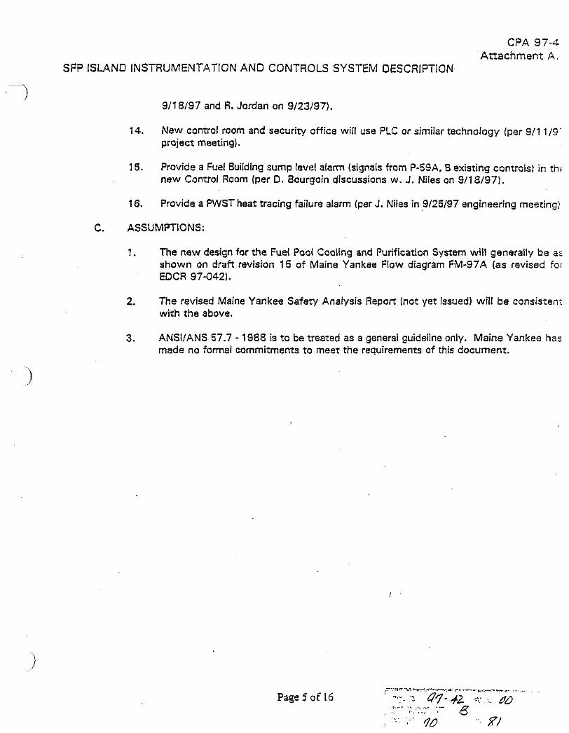
CPA 974 Attachment A .
SFP ISLANO INSTRUMENTATION AND CONTROLS SYSTEM DESCRlPTiON
911 8/97 and I?. Jordan on 9/23/97).
14. New control room and security office will use PLC or similar technology (per 911 i / C - project meeting).
15. Provide a Fuel Building sump level alarm (signals from P-59A, B existing conuols) in thi new Control Room (per 0. Bourgoin discussions w. J. Niles on 9/18/97).
16. Provide a PWST heat tracing failure alarm (per J. Niles in 9/25/97 engineering meeting!
C. ASSUMPTIONS:
1. The new design for the Fuel Pool Cooling and Purification System will generally be a- shown on draft revision 15 of Maine Yankee Flow diagram FW97A (as revised for EDCR 97-042).
2. The revised Maine Yankee Safety Analysis Repore (not yet issued) will be consisien; with the above.
3. ANSIIANS 57.7 - 1988 is to be treated as a general guideline only. Maine Yankee has made no formal commitments to meet the requirements of this document.

CPA 97-A Attachment A .
SFP ISLAND INSTRUMENTATION AND CONTROLS SYSTEM DESCRiPTlON
1. SYSTEM COMPONENTS INCLUDED IN THE INSTRUMENTATION AND CONTROLS GROUP SCOPE
A. The systemslequipment included in the instxmentaiion and controls group work scope for th Soent Fuel Pool lsland will include the following:
Soent Fuel Pool lsland Programmable Logic Control (PLC) System for Process lndicatior and Control -
This sysrem consists of an industrial hardened computer system which will be used fo the Spent Fuel Pool lsland Control Room monitoring, displays, and operator interface The PLC will generally accept inputs from all field devices needed for Control Roor; indications/alarms and will provide some outputs for secondary control of field device: from the new Control Room. The PLC may also contain control logic for the development of certain permissives and interlocks. It is anticipated that local hardwirec controls and indications will be the primary means of controlling the Spent Fuel Poo lsland equipment. The PLC displays are intended mainly for status monitoring anc alarming. Input/output signals are wired in the field to local I/O rack modules which then communicate with the PLC over a distributed control signal bus. In the new Control Room, the operator interfac* with the system will be via CRT monitors, keyboards, and cursor control devices such as mice or trackballs. It is likely that one or two stand-alone interfaces may also be provided in certain other areas of the plan1 on a permanent or temporary basis dcring decommissioning demolition activities.
Spent Fuel Pool lsland Plant Security Computer - A new security computer system will be implemented for the SFPl project. This system may be PLC based, similar to the above, or a special system which is tailored more to security applications. An operator interface will be provided for CASlSAS plant security functions. The sensor inputs (door switches, motion sensors, etc.) to the security system will be provided by others and wired to a centrally located junction box by others.
Control Room Console Furniture for the Above
PLC system interface with the following existing plant systems and equipment nor included in Table "A" (shown below) for alarming or display in the new Control Room. a. Meteorological Tower instruments for wind speed, wind direction, and air
temperature. b. Certain existing plant radiation ,monitors c. Fire pump P 4 and P-5 controls d. P-59A. 8 controls e. Plant electrical system
Provide PLC controllinterlock logic for :he following functions: a. Secondary Cooling Pump low suction pressure trips b. Cooling Pump STOP control
. .
Page 6 o f 16

CPA 07-, Atrrachment P
SF? ISLAND INSTRUMENTATION AND CONTROLS SYSTEM DESCRIPTION
6. Plant Instrumentation -
Providelmodify the instruments required to monitor the spent fuel pool island as lis: in Table A.
Page 7 of 16

CPA 97-3: AEachment A.t
? SF? ISLAND INSTRUMENTATION AND CONTROLS SYSTEM DESCRIPTION
TABLE A
SPENT FUEL POOL INSTRUMENTATION
FUEL POOL AREAINEL BUILDING SUMP INSTRUMENTS 1
INSTRUMENT NUMBER
Controller for Fuel Building Sump P-59A,
B
Fuel Pool High Level
Switch
' Fuel Pool Low Level Switch
PAB Lower
Level Pipt Tunnel
SE Come1 of Fuel Pool
(Middle Switch)
SE Comer of Fuel
Pool (East. Most
Switch)
DESCRIPTION
Existing
Existing
Existing
LOCATION
PLC
PLC
I
Square D Company, Model W-1 1 THIS INSTRUMENT TO
BE REMOVED AFTER FUNCTIONAL TESTING OF NEW LEVELTRANSMITTERS SO THAT CONTINUOUS ALARM CAPABILITY IS PROVIDED. Jo-Bell Type KC, 0-1 60°F, W.P. = 100, Spec. Grav. = 1.0, SIN 55046, 10 Amps, 1251250 VAC, 0.5Al120 VDC
THlS INSTRUMENT TO BE REMOVED AFTER FUNCTIONAL TESTING OF NEW LEVELTRANSMITTERS SO THAT CONTINUOUS ALARM CAPABILITY IS PROVIDED. Jo-Bell Type KC, 0-1 60°F, W.P. = 100, Spec. Grav. = 1.0, SIN 55047, 10 Amps, 1251250 VAC.
MISTING OR NEW?
LOCAL ONLY (L1 OR
WIRED TO PLC IPLCI
MFGR INFO. OR COMMENTS
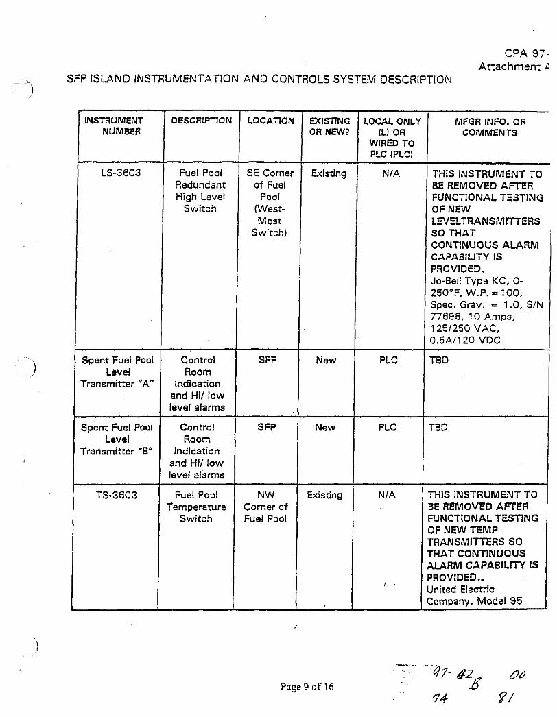
CPA 97- A t t a c h m e n t 1
- A SFP ISLAND INSTRUMENTATION AND CONTROLS SYSTEM DESCRIPTION )
INSTRUMENT DESCRIPTION NUMBER
LS-3603 Fuel Pool Redundant High Lave1
Switch
SE Corner of Fuel
Pool (West- Most
Switch)
Spent Fuel Pool Control Level Room
'ransmitter 'A" Indication and Hit low level alarms
Spent Fuel Pool Control Level Room
'ransmitter '8" Indication and Hit low level alarms
TS-3603 Fuel Pool Temperamre
Switch I
SFP
SFP
NW Comer of Fuel Pool
OR NEW? lL1 OR WIRED TO PLC (PLCl
Existing
New
New
Existing
Page 9 of 16
PLC
PLC
NIA
I .
MPGR INFO. OR COMMENTS
THIS INSTRUMENT TO BE REMOVED AFTER FUNCTIONAL TESTING OF NEW LNELTRANSMITTERS SO THAT CONTINUOUS ALARM CAPABILITY IS PROVIDED. Jo-Be!l Type KC, O- 250°F. W.P. = 100. Spec. Grav. = 1 .O, SIN 77695, 1 9 Amps, 1251250 VAC, 3.5A1120 VDC
rHlS INSTRUMENT TO 3E REMOVED AFTER YNCTIONAL TESTING IF NEW TEMP 'RANSMIrnRS SO HAT CONTINUOUS LARM CAPABILITY IS 'ROVIDED.. lnited Electric :om~anv. Model 95

CPA 97- r Attachment A.
-7 SF? ISLAND INSTRUMENTATION AND CONTROLS SYSTEM DESCRIFTION
INSTRUMENT NUMBER
MFGR INFO. OR COMMENTS
TaD
-
DESCRIPTION
-
MIST ING OR NEW?
LOCAL ONL'I (L) OR
WIRED TO PLC IPLCI
Spent Fuel Pool Temperature Transminer
"A"
Control Room
Indication and 1 st High
and Low Temp Alarm
Control Room
Indication and 2nd High
and Low Temp Alarm
New PLC
Spent Fuel Pool Temperature Transminer
"B"
New PLC
Spent Fuel Pool Temperature
Indicator
Local Indicator for
Direct Readout of Fuel Pool
Temperature
New 0-250 deg. F
P-59A Hours Top of MCC-11 8
Existing Simpson, 1 15 Volts, 60 Cycies
P-59A Hour Meter (No
lnstrument #)
P-598 Hour Meter (No
lnstrument #)
POI-3601
P-598 Hours Top of MCC-118
Existing Simpson, 11 5 Volts, 60 Cycles
Fuel Pool Filter
Differential Pressure Gauge
-
Barcon Instruments, 0- 30 PSI (1 12" tubing)
Outside Wall near lrumming
Room entrance
Existing
P-59A Discharge Pressure
Outside Wail near Jrumming
Room entrance
Existing Maxisafe Co. 0-60 PSI, (%' tubing)
Page 10 o f 16

C?A 97-4: Attachment A.E
SF? ISLAND INSTRUMENTATION AND CONTROLS SYSTEM DESCRIPTION
1 INSTRUMENT NUMBER
PI-33048
MFGR INFO. OR COMMENTS
LOCATION
Outside Wall near Drumming
Room entrance
P-598 Discharge Pressure
Maxisafe Co. 0-60 PSI, (YZ* tubing)
EXISTING OR NEW?
Existing
10' to l o a CPM, Serial # C031, P.O. MY-90, Dwg rr" 605501ASG01, Dare of Manuf. = 4/71, Power Inputs = Fuel Pool Platform, Westinghouse Nuclear Insirument and Control Oept.
LOCAL ONLY /Ll OR
WIRED TO PLC (PLCI
L
Radiation Monitor
F U ~ I POOI 1 Existing 1 PLC Mobile
Recorder for Spent Fuel Pool
Heat-up Rate Test
Thermocouplesl RTDs for Spent Fuel Pool Heat- up Rate Test
TED TED New (Temp.)
Yes Temporary recorder to be used for test only. Possibility of using Fluke Hydra Recorder in I&C Shop.
Temporary therrnocoupleslRTDs to be used for test only.
TED TED I New 1 Yes
FUEL POOL COOLING PRIMARY LOOP & PURIRCATION S Y S T E M INSTRUMENTS
Fuel Pool Cooling
Pump P-17A Discharge Pressure Gauge
Near P- 17A
Existing 3 0 Company, 0-1 00 PSI I%" tubing)
,-..~ ': . . 47 - .pL d o
Page 11 of 16 a '7b 2 I
- ~~ ~
PI-3601 8 Fuel Pool Cooling
Pump P-178 Discharge Pressure
~~ -
Near P- 178
~
Existing ~p
L 3 0 Company, 0-1 00 PSI I:$" tubing)

CPA 97-. Attachment P
SFP ISLAND INSTRUMENTATION AND CONTROLS SYSTEM DESCRIPTION
MISTING LOCAL ONL' OR NEW? (L1 OR
WIRED TO PLC (PLCI -I---
-
INSTRUMENT NUMBER
MFGR INFO. OR COMMENTS
3D Company 0-1 60 PSI , ( % " tubing) 1
I
Fuel Pool Purification Pump P-85 Discharge Pressure
Near P-85 Existing
Pri. Side E- 25 Inlet Temp.
Indicator
On Pipe near FP-14
- - Ashcroft Company, O- 200" F
Ashcroft Company, O- 200" F
I
Rosemount 1 15 1
Existing
Existing
Pri. Side E- 25 Outlet
Temp. lndicator
Primary Make-up
Tank (PWST) Level
Transminer
On Pipe near FP-15
PWST
Primary to Secondary
Leak
Primary to Secondary dP
Indicating Switch
P-17A, 8 Pump Area
Detsction
P-85 Discharge Pressure
Transmitter
P-85 Discharge Pressure
P-85 Discharge
New PLC
P-17A Discharge Pressure
Transmitter
P-17A Discharge Pressure
P-17A Discharge
P-178 Discharge Pressure
Transmitter
P-178 Discharge Pressure
P-178 Discharge

CPA 97-L Attachment A
SF? ISLAND INSTRUMENTATION AND CONTROLS SYSTEM DESCRlPTiON
I I PLC (PCCI I FUEL POOL COOLING SECONDARY LOOP INSTRUMENTS
I I
-
Level lndicator for new
(Bladder type) Secondary
Surge Tank
INSTRUMENT NUMBER
- --
Pressure lndicator
DESCRIPTION
Sec. Surge Tank
LOCATION
Level Transmitter for new (Bladder
vpe) Secondary Surge Taaik
Sec. Side E-25 Inlet Temp.
lndicator
WlSTlNG OR NEW?
LOCAL ONLY ILI OR
WIRED TO
Pressure Transmitter
Local lndicator
MFGR INFO. OR COMMENTS
Sec. Surge ! Tank
TBD
Sec. Side E-25 Outlet Temp.
lndicator
Local lndicator
Secondary Coolant "A" Pump Suct Press. Sw.
Secondary Coolant "A" Pump Disch Press Gauge
Secondary Coolant "8" Pump Disch Press Gauge
Low Press A lam in Control Room
Local Gauge
Local Gauge
New
New
A t Pump
A t Pump
Ashcroft Company, O- 200" F (or Equiv.)
New
PLC
PLC
TED
TBD
L
I I
Secondary Low Press Coolant "8" Alarm in Suction Pump Suct Control Press. Sw.
Ashcroft Company, O- 200' F (or Equiv.)
New
-
Page 13 o f 16
Pump Suction
tine
L TBD
New PLC
! .
TED

CPA 97-52 At tachment A. E
- 1 SFP ISLAND INSTRUMENTATION AND CONTROLS SYSTEM DESCRIPTION
INSTRUMENT NUMBER
Secondary Coolant "A"
Pump Discharge Pressure
Transmitter
Secondary Coolant "B"
Pump Discharge Pressure
Transminer
Spent Resin Pit Sump Level
Switch
Coolant Radiation Monitor
- -
LOCATION
Pump Discharge
Pump Discharge
Spent Resin Pit
TBD 1
DESCRIPTION
Control Room
lndication
Control Room
Indication
High Level Alarm
Secondary Leak1
Radiation Detection
FUEL BUILDING VENTllATlON SYSTEM INSTRUMENTS
Secondary I Primary to I
Electrical Equip Roam Area Temp Local
lndicator
I I ! - r--*- : y:.3 97- 42 ~ c +
Page l4of16 ; : 6 1 :s:.c 5 qq as I
Radiation Monitor for Ventilation
Exhaust
Fuel Pool Area (N. End) Temp Local Indicator
TS- 1 106
MFGR INFO. OR COMMENTS
TBD
TED
TED
TED
EXlSTlNG OR NFN?
New
New
Existing
New 1
TBD
TBD
TBD
TED
PRI WATER STORAGE TANK (PWST) TK-16
TBD
LOCAL ONLY ILI OR
WIRED TO PLC IPLC)
PLC
PLC
PLC
PLC (
PWST Aux. Steam Temp.
Control
New
New
TBD
PWST Instrument
Shed
PLC
L
- ~
New
TED
TBD
Existing
L ~
TBD
NI A This Instrument t o be Removed along with PWST Steam Heat. UE Model 68s. Options 15 19.0-250 dea. F

CPA 97- Attachment A
I SFP ISLAND INSTRUMENTATION AND CONTROLS SYSTEIV DESCRIPTION
Page 15 o f 16
S-35
LT-400 1
INSTRUMENT NUMBER
T1-4002
TS-4003
DESCRItTON
PWST Local Temp Gauge
PWST HiILo Temperature
Alarm
' Local Level Gauge
PWST Level
LOCA'ilON
PWST Instrument
Shed
PWST Instrument
Shed
MISTING OR NNV?
Existing
Existing
LOCAL ONLY (Ll OR
WIRED TO PLC (PLCI
L
PLC
PINST instrument
Shed
PWST Instrument
Shed
MFGR INFO. OR COMMENTS
Ashcroft, 0-200 deg. F with 1.5", 304 SST RF Flange Conn.
UE Model 6BS (F-402- 60s-5101)
Existing
Existing
L
PLC
Duragauge, 0-45 Ft.
Rosemount 1 15 1 DPE22
CPA 97-4 Attachment A
SFP ISLAND INSTRUMENTATION AND CONTROLS SYSTEM DESCRIPTION
1 11. SYSTEM ARRANGEMENT
Later
111, SYSTEM OPERATlON
Later
IV. OTHER
Later
Page 16 o f 16