concentric tube heat exchanger - · pdf filethermalfluids lab concentric tube heat exchanger...
TRANSCRIPT

THERMALFLUIDS LAB CONCENTRIC TUBE HEAT EXCHANGER
EMD5MIA
Page | 1
TITLE: CONCENTRIC TUBE HEAT EXCHANGER
1.0 INTRODUCTION
A heat exchanger is an equipment in which heat exchange takes place between
2fluids that enter and exit at different temperatures. The main function of heatexchanger is to
either remove heat from a hot fluid or to add heat to the cold fluid. The direction of fluid
motion inside the heat exchanger can normally categorised as parallel flow, counter flow and
cross flow. In this experiment, we study only the parallel flow and counter flow. For parallel
flow, also known as co-current flow, both the hot and cold fluids flow in the same direction.
Both the fluids enter and exit the heat exchanger on the same ends. For counter flow, both the
hot and cold fluids flow in the opposite direction. Both the fluids enter and exit the heat
exchanger on the opposite ends. In this experiment, we focused on the shell and tube heat
exchanger. Examples in practice in which flowing fluids exchange heat are air intercoolers
and preheaters, condensers and boilers in steam plant, condensers, condensers and
evaporators in refrigeration units, and many other industrial process in which a liquid or gas
is required to be either cooled or heated.
There are three main types of heat exchanger:
i. Recuperator
Fluids exchanging heat are on either side of a dividing wall
ii. Regenerator
Hot and cold fluids pass alternatively a sink and a source for heat flow
iii. Evaporative Type
A liquid is cooled evaporatively and continuously in the same space as the coolant.
An example of the latter type is the cooling tower. Very often when term” heat
exchanger” is used it refers to the recuperative type, which is by far the most commonly used in
engineering practice. The main purpose of heat exchanger is to remove the heat from the hot

THERMALFLUIDS LAB CONCENTRIC TUBE HEAT EXCHANGER
EMD5MIA
Page | 2
fluid and transfer it into the cold fluid. There are 3 types of heat exchanger, parallel flow, counter
flow, and cross flow. However, in this experiment, we only consider the counter-flow heat
exchanger and parallel flow. Counter flow exists when the two fluids flow in opposite directions.
Each of the fluids enters the heat exchanger at opposite ends. Because the cooler fluid exits the
counter flow heat exchanger at the end where the hot fluid enters the heat exchanger, the cooler
fluid will approach the inlet temperature of the hot fluid. Parallel flow exists when two fluids
flow in parallel directions. Each of the fluids enters the heat exchanger at parallel end.
Figure 1: Counter-flow heat exchanger Figure 2: Parallel-flow heat exchanger
2.0 OBJECTIVE
The main objective for this experiment is to demonstrate the effect of the flow rate variation on
the performance characteristics of a counter-flow and parallel flow concentric tube heat
exchanger. Specific objectives for this experiment include:
i. Learning how the operation of concentric tube heat exchanger.
ii. Developing a set of experiments to obtain statistically significant trends for the
overall heat transfer coefficient and the inside heat transfer coefficient as a function
of water velocity.

THERMALFLUIDS LAB CONCENTRIC TUBE HEAT EXCHANGER
EMD5MIA
Page | 3
iii. Observing the difference between parallel-flow and counter flow operation of the heat
exchanger.
3.0 THEORETICAL BACKGROUND
Background
The way that a heat exchanger works is hot water and cold water enter the exchanger,
where the process of cold water gaining some heat and the hot water losing some takes place,
before they both exit the exchanger. What is actually happening is, the hot water is heating either
the inside or the outside of the tubes in the exchanger, depending on where it is flowing, by what
is known as convection.
Then the heat is conducted through the tubes to the other side, either the outside or the
inside, where it is then convected back into the cold water raising its temperature. Convection is
a mode of heat transfer that involves motion of some fluid that either absorbs heat from a source
or gives heat to some surrounding. Conduction is a mode of heat transfer in which the heat is
moving through a stationary object or fluid. For a heat exchanger that flows parallel or counter
current then the coefficient of heat transfer is called the over all coefficient of heat transfer. It is
calculated using the log mean temperature difference, which is found two different ways,
depending of whether the flow is parallel or counter.
A heat exchanger is a device by which thermal energy is transferred from one fluid to
another. The types of heat exchangers to be tested in this experiment are called single-pass,
parallel-flow and counter-flow concentric tube heat exchangers. In a parallel-flow heat
exchanger, the working fluids flow in the same direction. In the counter flow exchanger, the
fluids flow in parallel but opposite directions.

THERMALFLUIDS LAB CONCENTRIC TUBE HEAT EXCHANGER
EMD5MIA
Page | 4
Figure 3: Concentric Tube Heat Exchangers
The variables that affect the performance of a heat exchanger are the fluids’ physical
properties, the fluids’ mass flow rates, the inlet temperature of the fluids, the physical properties
of the heat exchanger materials, the configuration and area of the heat transfer surfaces, the
extent of scale or deposits on the heat transfer surfaces, and the ambient conditions.
The equations for calculating the performance characteristics : power emitted, power
absorbed, power lost, efficiency (η); logarithmic mean temperature difference (Δ ), and overall
heat transfer coefficient (U).
The efficiency for the cold medium is:
= ( - / - ) x 100

THERMALFLUIDS LAB CONCENTRIC TUBE HEAT EXCHANGER
EMD5MIA
Page | 5
The efficiency for the hot medium is:
= ( - / - ) x 100
The mean temperature efficiency is:
= ( + ) / 2
The power emitted is given below ( where is the volumetric flow rate of the hot fluid) :
Power Emitted = ( - )
The power absorbed is given below (where is the volumetric flow rate of the cold fluid) :
Power Absorbed = ( - )
The power lost is therefore:
Power lost = Power Emitted – Power Absorbed
The overall efficiency (η) is:
η = (Power Absorbed/Power Emitted) x 100
The logarithmic mean temperature difference (Δ ) is:
Δ = (Δ - Δ ) /
= ( - ) – ( - ) / ln [( - ) / ( - )]

THERMALFLUIDS LAB CONCENTRIC TUBE HEAT EXCHANGER
EMD5MIA
Page | 6
The overall heat transfer coefficient (U) is :
U = Power Absorbed / Δ
where the surface area ( ) for this heat exchanger is 0.067 m².
Figure 4: Graph of Parallel flow
Figure 5: Graph of Counter Flow
Figure 6: Schematic Diagram of Parallel
Flow
Figure 7: Schematic Diagram of Counter
Flow

THERMALFLUIDS LAB CONCENTRIC TUBE HEAT EXCHANGER
EMD5MIA
Page | 7
Figure 8 : Calculation Temperature of
Parallel-Flow
Figure 9 : Calculation Temperature of
Counter-Flow
4.0 APPARATUS
The apparatus for this experiment is the H900 Concentric Tube Heat Exchanger. This
apparatus has a tank with a heater inside to heat water to a specified temperature. The
temperature setting is adjusted at the thermostat on the front panel. Once the water is heated to
the desired temperature it is transferred by a water pump next to the tank. On the pump there is a
knob which varies the pump pressure. When using a volumetric flow rate above 2 L/min. the
switch should be set to the highest pressure.
The hot water is pumped through a pipe to an insulated tube for which heat will be
exchanged. The actual heat exchange takes place in the insulated tubing for which cold water
flows concentricity around the hot water tube in two different flow arrangements. These two
arrangements, parallel and counter flow, can be changed by opening and closing certain valves
within the network of hot and cold water tubing. Each flow arrangement is shown on a diagram
located on the front panel. It is worthwhile to note that the temperature at cold-in changes to
temperature at cold-out when a counter flow arrangement is used. The same situation applies to
the temperature at cold-out, which changes to temperature cold-in for the counter flow. The other
readings remain the same. The flow rates can be adjusted for both cold and hot water by turning

THERMALFLUIDS LAB CONCENTRIC TUBE HEAT EXCHANGER
EMD5MIA
Page | 8
the valve knobs on the right side of the panel. Thermometers are located at the inlet, exit and
middle of the insulated heat exchanger tubing for both hot and cold water.
Figure 10: Concentric Tube Heat Exchanger
Figure 11: Digital clock
Figure 12 : Heat Exchanger Apparatus
System Diagram
Figure 13 : Parallel Flow and Counter Flow of
Valve Diagram

THERMALFLUIDS LAB CONCENTRIC TUBE HEAT EXCHANGER
EMD5MIA
Page | 9
5.0 EXPERIMENTAL PROCEDURE
1. Configure the experiment for counter-flow heat exchanger operation. The required hot
water inlet temperature to = 60 ºC with the decade switch is set. Then, the cold
water volumetric flow rate ( ) to run at a constant 2,000 cm³/min is also set.
2. Initially the hot fluid volumetric flow rate ( ) to 1,000 cm³/min is set. After 5 minutes
the six temperature readings are recorded in following table. Then, this for volumetric
flow rates of 2,000, 3,000 and 4,000 cm³/min is repeated.
3. Look up values for density ( c hand ) and constant pressure specific heat ( pc phC andC )
for the cold fluids at a temperature of ,c inT and for the hot fluids at a temperature of ,h inT .
4. Using the data, the following heat exchanger performance factors: power emitted, power
absorbed, power lost, efficiency ( ), logarithmic mean temperature difference ( mT ),
and overall heat transfer coefficient (U ) are calculated and recorded in the table.
5. The experiment is repeated and set up for parallel flow with the same steps for the
counter flow.
THERMALFLUIDS LAB CONCENTRIC TUBE HEAT EXCHANGER
EMD5MIA
Page | 10
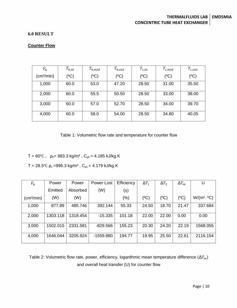
6.0 RESULT
Counter Flow
(cm³/min)
(ºC)
(ºC)
(ºC)
(ºC)
(ºC)
(ºC)
1,000 60.0 53.0 47.20 28.50 31.00 35.50
2,000 60.0 55.5 50.50 28.50 33.00 38.00
3,000 60.0 57.0 52.70 28.50 34.00 39.70
4,000 60.0 58.0 54.00 28.50 34.80 40.05
Table 1: Volumetric flow rate and temperature for counter flow
T = 60 , ρh= 983.3 kg/m³ , Cph = 4.185 kJ/kg.K
T = 28.5 ρc =996.3 kg/m³ , Cpc = 4.179 kJ/kg.K
(cm³/min)
Power
Emitted
(W)
Power
Absorbed
(W)
Power Lost
(W)
Efficiency
( )
(%)
Δ
(ºC)
Δ
(ºC)
Δ
(ºC)
U
W/(m². ºC)
1,000 877.89 485.746 392.144 55.33 24.50 18.70 21.47 337.684
2,000 1303.118 1318.454 -15.335 101.18 22.00 22.00 0.00 0.00
3,000 1502.015 2331.581 -829.566 155.23 20.30 24.20 22.19 1568.055
4,000 1646.044 3205.924 -1559.880 194.77 19.95 25.50 22.61 2116.154
Table 2: Volumetric flow rate, power, efficiency, logarithmic mean temperature difference (Δ )
and overall heat transfer (U) for counter flow

THERMALFLUIDS LAB CONCENTRIC TUBE HEAT EXCHANGER
EMD5MIA
Page | 11
Parallel Flow
(cm³/min)
(ºC)
(ºC)
(ºC)
(ºC)
(ºC)
(ºC)
1,000 60 52.00 47.90 29.00 33.00 34.50
2,000 60 55.00 51.00 29.00 34.50 35.60
3,000 60 56.00 53.00 29.00 35.00 37.70
4,000 60 57.00 54.00 29.00 36.00 39.50
Table 3: Volumetric flow rate and temperature for parallel flow.
T = 60 , ρh= 983.3 kg/m³ , Cph = 4.185 kJ/kg.K
T = 29 ρc =996.2 kg/m³ , Cpc = 4.178 kJ/kg.K
(cm³/min)
Power
Emitted
(W)
Power
Absorbed
(W)
Power
Lost (W)
Efficiency
( )
(%)
Δ
(ºC)
Δ
(ºC)
Δ
(ºC)
U
W/(m². ºC)
1,000 829.881 381.528 448.353 45.97 25.50 18.90 22.04 258.421
2,000 1234.533 915.667 318.866 74.17 24.40 22.00 23.18 589.607
3,000 1440.289 1810.524 -370.240 125.71 22.30 24.00 23.14 1167.814
4,000 1646.044 2913.487 -1267.440 177.00 20.50 25.00 22.68 1917.692
Table 4: Volumetric flow rate, power, efficiency, logarithmic mean temperature difference (Δ )
and overall heat transfer (U) for parallel flow.

THERMALFLUIDS LAB CONCENTRIC TUBE HEAT EXCHANGER
EMD5MIA
Page | 12
7.0 SAMPLE CALCULATION
Note:
The liquid properties refer table A-2 Boiling and Freezing Point Properties
This calculation parallel flow and counter flow has been taken the data 1000 cm³/min
cold water and 1000 cm³/min hot water volume flow rate.
Counter Flow
By refer to the table of saturated water properties :
At T= 60
ρh = 983.3 kg/m³
Cph = 4.185 kJ/kg.K
At T= 28.5
We need to do interpolation to find ρC and Cpc .
At T= 25 , ρ = 997 kg/m³
At T= 30 , ρ = 996 kg/m³
(30 – 28.5) / (30 – 25) = (996 - c ) / (996 – 997)
c = 996.3 kg/m³
At T= 25 , Cp = 4.180 kJ/kg.K
At T= 30 , Cp = 4.178 kJ/kg.K
(30 – 28.5) / (30 – 25) = (4.178 - Cp) / (4.178 – 4.180)
Cpc = 4.179 kJ/kg.K
Power Emitted = ( - )
= (1000 x 1/60 x 1/ ) m³/s x 983.3 kg/m³ x 4.185 kJ/kg.K x (60 – 47.2)K
= 877.89W
Power Absorbed = ( - )

THERMALFLUIDS LAB CONCENTRIC TUBE HEAT EXCHANGER
EMD5MIA
Page | 13
= (1000 x 1/60 x 1/ ) m³/s x 996.3 kg/m³ x 4.179 kJ/kg.K x (35.5-28.5)K
= 485.746W
Power lost = Power Emitted – Power Absorbed
= 877.89 – 485.746
= 392.144W
The overall efficiency (η) is:
η = (Power Absorbed/Power Emitted) x 100
= (485.746 / 877.89) x 100
= 55.33 %
The logarithmic mean temperature difference (Δ ) is:
Δ = (Δ - Δ ) / Δ
Δ
Δ = ( - )
= (60 – 35.5)
= 24.5 ºC
Δ = ( - )
= (47.2 – 28.5)
= 18.7 ºC
Δ = (Δ - Δ ) / Δ
Δ
= (24.5 –18.7) / ln (24.5/18.7)
= 21.47 ºC
The overall heat transfer coefficient (U) is :

THERMALFLUIDS LAB CONCENTRIC TUBE HEAT EXCHANGER
EMD5MIA
Page | 14
U = Power Absorbed / Δ
U = 485.746/ (0.067x21.47)
= 337.684 W/m². ºC
Parallel Flow
By refer to the table of saturated water properties :
At T= 60
ρh = 983.3 kg/m³
Cph = 4.185 kJ/kg.K
At T= 28.5
We need to do interpolation to find ρC and Cpc .
At T= 25 , ρ = 997 kg/m³
At T= 30 , ρ = 996 kg/m³
(30 – 29) / (30 – 25) = (996 - c ) / (996 – 997)
c = 996.2 kg/m³
At T= 25 , Cp = 4.180 kJ/kg.K
At T= 30 , Cp = 4.178 kJ/kg.K
(30 – 29) / (30 – 25) = (4.178 - Cp) / (4.178 – 4.180)
Cpc = 4.178 kJ/kg.K
Power Emitted = ( - )
= (1000 x 1/60 x 1/ ) m³/s x 983.3 kg/m³ x 4.185 kJ/kg.K x (60 – 47.9)K
= 829.881W
Power Absorbed = ( - )
= (1000 x 1/60 x 1/ ) m³/s x 996.2kg/m³ x 4.178 kJ/kg.K x (34.5-29)K

THERMALFLUIDS LAB CONCENTRIC TUBE HEAT EXCHANGER
EMD5MIA
Page | 15
= 381.528 W
Power lost = Power Emitted – Power Absorbed
= 829.881– 381.53
= 448.353 W
The overall efficiency (η) is:
η = (Power Absorbed/Power Emitted) x 100
= (381.528 / 829.881) x 100
= 45.97 %
The logarithmic mean temperature difference (Δ ) is:
Δ = (Δ - Δ ) / Δ
Δ
Δ = ( - )
= (60 – 34.5)
= 25.5 ºC
Δ = ( - )
= (47.9 – 29)
= 18.9 ºC
Δ = (Δ - Δ ) / Δ
Δ
= (25.5 –18.9) / ln (25.5/18.9)
= 22.04 ºC
The overall heat transfer coefficient (U) is :
U = Power Absorbed / Δ
U = 381.528 / (0.067x22.04) = 258.421 W/m². ºC

THERMALFLUIDS LAB CONCENTRIC TUBE HEAT EXCHANGER
EMD5MIA
Page | 16
8.0 REFERENCE
1. Thermodynamics An Engineering Approach Sixth Edition (SI Units) by Yunus A. Cengel
And Michael A. Boles. (Mc Graw Hill)
2. http://en.wikipedia.org/wiki/Heat_exchanger