computer vision system for a wheelchair for children with
TRANSCRIPT
TFG EN ENGINYERIA INFORMATICA, ESCOLA D’ENGINYERIA (EE), UNIVERSITAT AUTONOMA DE BARCELONA (UAB)
Computer Vision System for a wheelchairfor children with functional diversity
Jaime Cabrera Calderon
Abstract–This paper contains all the information related with the definition, development and results of aComputer Vision System project that will be implemented in an existing wheelchair. The project isbased on a low cost philosophy as is the existing wheelchair as well. The main objective of the projectis to provide the wheelchair with functionalities that allow giving a certain autonomy to children whodo not have any, being a project aimed at solving a real need of the community and improving theliving conditions of children with functional diversity. Children can choose which corner of the roomto go to, where there will be a visual stimulus, and the wheelchair goes to that place.Keywords–Low-cost, Computer Vision, QR code, Bluetooth, Localization
Resum–Aquest document conte tota la informacio relacionada amb la definicio, el desenvolupament i elsresultats d’un projecte de sistema de visio artificial que s’implementara en una cadira de rodesexistent. El projecte es basa en una filosofia de baix cost, com tambe ho es la cadira de rodesexistent. L’objectiu principal del projecte es proporcionar a la cadira funcionalitats que permetinatorgar certa autonomia als nens que no tenen cap, sent un projecte destinat a resoldre unanecessitat real de la comunitat i millorar les condicions de vida dels nens amb pluridiscapacitat. Elsnens poden triar a que cantonada de l’habitacio anar, on hi haura un estımul visual, y la cadira derodes anira al lloc.
Paraules clau–Low-cost, Computer Vision, QR code, Bluetooth, Localization
F
• E-mail de contacte: [email protected]• Mencio realitzada: Enginyeria de Computacio• Treball tutoritzat per: Fernando Vilarino Freire, CVC• Curs 2018/19
June 2019, Escola d’Enginyeria (UAB)

2 EE/UAB TFG INFORMATICA: Computer Vision System for a wheelchair
1 INTRODUCTION
THIS project tackles the creation of a ComputerVision-based system that allows children with func-tional diversity to have autonomy of displacement
within a room, through the implementation of our modularsystem into an existing low cost wheelchair.
The project’s aims are aligned with the Goals 3 (GoodHealth and Well-Being), 10 (Reduce Inequalities) and 12(Responsible Production and Consumption) of the Sustain-able Development Goals [1] because of the social impact,the search of equal conditions and the philosophy of recy-cling and low cost. The project follows the service learningmethodology [2] since the objective is to learn new knowl-edge in an academic way while developing a project fo-cused on community service.
This module will allow the low cost wheelchair to au-tonomously move in a room, to arrive at different key pointswhere there will be different visual stimulus. This smallelement of autonomy represents a huge change in the chil-dren’s life since, so far, every displacement must be com-pulsory monitored by an adult. Especially, this will rep-resent an enormous improvement for patients of cerebralparalysis, who may have a wide variety of unimpaired cog-nitive functionalities but affected motor functionalities.
In Section 2, we will enumerate the main objectives ofour system. In Section 3 we will present the state-of-the-artof the project. In Section 4 we will describe the hardwaresystem. In Section 5 we will define the proof of concept andthe final system prototype. In section 6 we will describe thesoftware system. In Section 7 we will describe our experi-mental set-up. In Section 8 we will show the results of theprojects, in Section 9 the discussion and finally, in Section10, the final conclusions.
2 OBJECTIVES
The main objectives of the project are:
1. Plan and create the working environment for thewheelchair and the computer vision system (sceneconfiguration).
2. Design and implement a physical interaction device(buttons pad) for the selection of destination and itsassociated software module.
3. Develop a robust module for the search of the destina-tion.
4. Develop a displacement module to reach to the se-lected destination.
5. Implement a small proof of concept for validation.
6. Build up a final working prototype integrated into thelow cost wheelchair.
3 STATE OF THE ART
In this section we will introduce the state-of-the-art onwheelchairs for children with functional diversity, themethodology of Service Learning (particularly suited to thisproject), and the available Computer Vision systems.
3.1 Wheelchairs for children with functionaldiversity
Currently there exists some electric wheelchairs that can becontrolled by the user. For example two popular models arethe KuiGu Electric Wheelchair Foldable, very popular onAmazon1, and Q700 M SEDEO PRO, which can be boughtin the official page2. The main problem with these kinds ofwheelchairs is the price, which is between 1500 and 7000Euros. Depending on the model, the materials and the func-tionalities the wheelchair will have different price. On theother hand, we cannot access to the software and changeit to implement, in this case, a Computer Vision Systemmodule. This is why the low-cost wheelchair [5] that NexeFundacio [6] offers is perfect for both reasons: as cheap aspossible and access to the code.
3.2 Service Learning
Service Learning is an educational approach focused onlearning during a project development which will have asocial impact [3]. This project makes sense within this areafor its service to the community, in this case children withfunctional diversity, and for its learning and research side todevelop a functional system.
Moreover, the project satisfies the requirements of a Ser-vice Learning project [4].
• It contributes to the community
• It takes awareness of participating in the benefit of thecommunity
• It obtains evidence of learning about curriculum com-petencies
• It shows evidence of a thoughtful process
• It participates in the adjustment of the intervention inthe framework of the Service Learning.
Furthermore, as an student’s project, we participated inthe detection of needs, in the design of the intervention andwe chose this Service Learning project having other op-tions.
3.3 Location of the wheelchair in a room
Some authors have investigated about the use of QR codesto locate a system in a indoors space [?]. QR codes are land-marks that provide information when a system scan them.The QR code information can be filled by the user in orderto give to the system useful information that will be usedfor instance to locate the different destination [?]. This ap-proach is quite robust and well understood which makes ita very good candidate for our purpose.
1urlhttps://www.amazon.com/KuiGu-Wheelchair-Intelligent-Automatic-Lightweight/dp/B07QX7Q37R
2urlhttps://www.sunrisemedical.es/sillas-de-ruedas/quickie/sillas-de-ruedas-electricas/q700-m-sedeo-pro

Jaime Cabrera Calderon: Computer Vision System for a wheelchair for children with functional diversity 3
4 HARDWARE SYSTEM DESCRIPTION
The proposed system will be a module that will be addedto an existing wheelchair to make it able to have autonomy.That means that the electric wheelchair without this mod-ule just can be controlled by a third person, but with thisComputer Vision module, the wheelchair will be upgradedwith a new functionality. The system will be implementedas a system that does not need to be connected physicallyto the wheelchair, the only thing needed to make it work isto plug it in the wheelchair and connect it via Bluetooth.
The system consist of the following elements (see Figure1):
Fig. 1: Hardware elements
1. The wheelchair offered by Nexe fundacio
2. A web cam
3. The buttons pad to select the destination
4. A Raspberry pi 3B+ which will run the system
5. A motor controller to control the servo that moves thewheels (only needed for the proof of concept)
6. A servo motor that will move the web cam horizontally
4.1 Hardware architecture
Fig. 2: Hardware diagram
The system consists of a Raspberry Pi 3B+, which willbe responsible for running all Computer Vision software,which means that the system will run independently in thechair without requiring any type of connection with a server.The Raspberry Pi will have connected the buttons pad, aswell as WebCam. The chosen camera is the Logitech C270because it is very recommended for Computer Vision pur-poses according to some forums on the internet3. The Rasp-berry Pi will also be connected via Bluetooth to the arduinoof the wheelchair to send the movement orders. Refer to thefigures 1 and 2 to visualize the mentioned elements.
4.2 Buttons pad for destination selectionThe selection of the destination will be done through fourcoloured buttons. The button system will be a structurecreated on a conventional computer keyboard. Making useof this technology gives you advantages such as the price,since you can use a keyboard that you no longer use at homeor a second hand keyboard. On the other hand, the connec-tion to the Raspberry Pi 3 is very simple, just connectingthe USB cable or the wireless receptor if it is a wirelesskeyboard.
Fig. 3: Keyboard button structure example
As you can see in the Figure 3, when a button is pushed,the structure pushes determined keys that the system detectsand knows which button is the pushed.
5 PROOF OF CONCEPT AND FINAL PROTO-TYPE
5.1 Configuration of the sceneThe system will work in a single room and it is designed tofind four QR codes that will be located in the corners of theroom.
Below is an example of placing two QR codes in a room,one placed in a corner clinging to the ends and anotherclinging to the wall in the plane. Once the room has allthe codes properly located, the system can work
5.2 Proof of conceptIn order to develop the software and all the functionalitiesbefore testing it in the wheelchair, we created a proof ofconcept. This proof of concept is based on a robotic carchassis with two motors for the wheels, a servo motor tomove the camera horizontally, the raspberry pi, a motorcontroller and a powerbank. With all these componentswe could create a working robot to develop and test all thethings that we needed. You can see a real picture of theproof of concept in Figure 5
3urlhttps://www.chiefdelphi.com/t/best-cameras-for-computer-

4 EE/UAB TFG INFORMATICA: Computer Vision System for a wheelchair
Fig. 4: Example of placement of QR codes in a room
Fig. 5: Real picture of the prototype
Fig. 6: Hardware connection scheme for the proof of con-cept model
5.3 Final prototype
The final prototype consist of the wheelchair provided byNexe Fundacio and the functional version of the ComputerVision System plugged, implemented and adapted to thewheelchair. Check Figure 7
vision/155702
Fig. 7: Final prototype with the Computer Vision Systemlocated at the top
6 SOFTWARE SYSTEM DESCRIPTION
6.1 Software architectureIn Figure 8 you can see the software architecture of the sys-tem. As you can see, the software consist of four differentmodules and each module has a single finality.
• Interaction Module
• Search Module
• Memory Module
• Displacement Module
The Interaction Module waits for the user to select a des-tination and once it is selected, it sends the destination tothe Search Module. The objective of the Search Moduleis to search for the destination QR code in the room. TheDisplacement module performs all the necessary displace-ments and trajectories to arrive at the desired points. Fi-nally, the Memory Module can remember positions and in-formation of other moments of the execution to arrive at adesired point when it is not visible. All these modules aredifferent python libraries in order to have the functionalitiesdivided into different files and make it easier to understandand modify. You can see the relations and behaviour be-tween each module in Figure 8
For more information about the software system, see An-nex 2: Sequence diagram of the software.

Jaime Cabrera Calderon: Computer Vision System for a wheelchair for children with functional diversity 5
Fig. 8: Software diagram
6.2 Search module and environment infor-mation
This part explains in details how the system can know whereit is through the use of QR codes.
6.2.1 QR code detection
For the detection of QR codes the pyzbar[16] library will beused. This library makes the detection of QR codes and wecan obtain this information very useful to know the positionof the chair. This library gets an image as an input, theimage is analysed and the library give us all the QR codesdetected within a variable. Of these codes we are interestedin knowing the coordinates of the points that make up thefour corners, the area and the total number of pixels thatoccupy the code within the total image.
When the library detects the points, it assigns the pointsdepending on its position in the image, not depending onthe code. This fact causes the points to change dependingon the position and orientation of the code. For this reason,the code had to be modified so that the order was always thesame. Therefore, the position of the points will always be:
• Up left: Point 1
• Up right: Point 2
• Down left: Point 3
• Down right: Point 4
Fig. 9: Points detection
6.2.2 Camera behaviour
The camera will capture images of the room to find out whatposition it is. The camera will be at the top of a very stablerotating 180o axis so that the image received is as faithful aspossible. The camera will turn to different position to checkall the 180o and then will wait until the system turns backto check the other side of the room. This is done this waybecause there not exists 360 degrees servo motors.
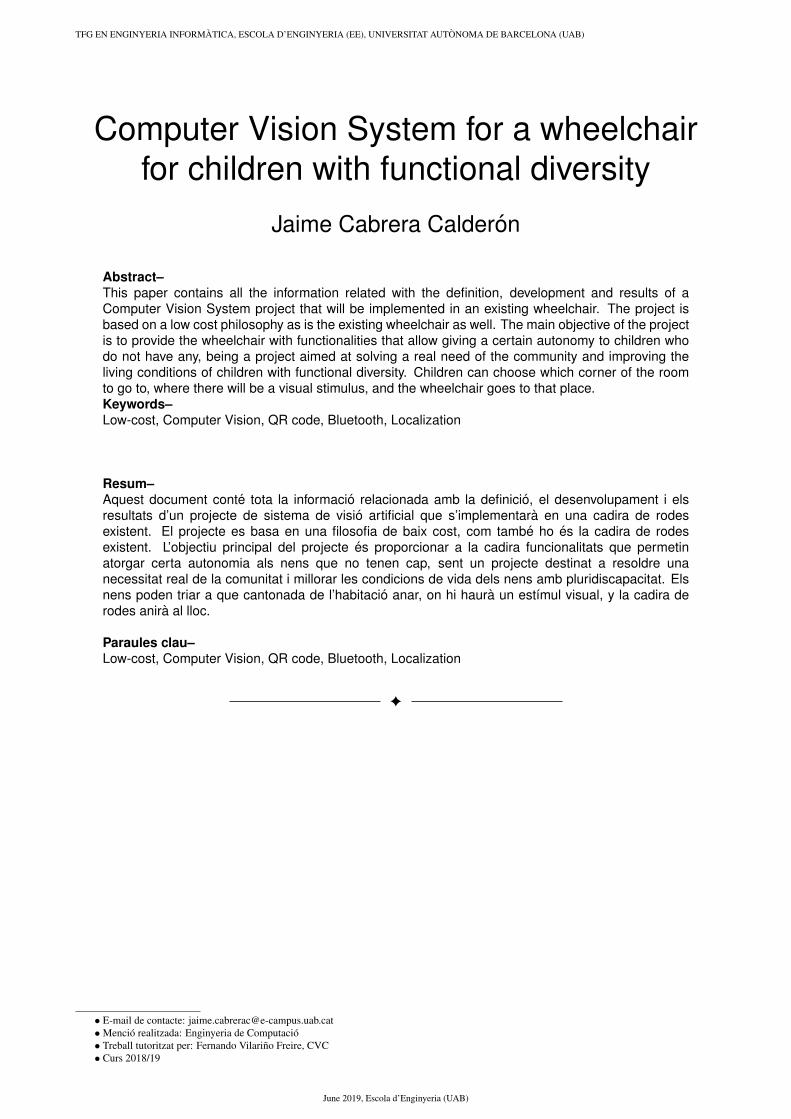
6.2.3 QR position detection
For the detection of the position of the QR codes, the lengthof the lines between the points p1-p4 and p2-p3 will betaken into account. Thanks to these two lines, you can knowif the camera is looking at the code from the right, the leftor from the center. That is why the percentage of differencein size between the two lines will be taken into account.Thanks to using percentages, this system will always workregardless of the size of the code or its position or orien-tation. In total 5 positions will be detected: left 2, left 1,center, right 1, right 2 (from maximum right to maximumleft in order).
In addition to this information, the distance to which theQR code is found is taken into account, since depending onhow far it is, the percentages to detect the orientation willhave to change. This distance will also give us more infor-mation related to the environment that will be useful to getfrom one QR code to another. The ’dist’ variable in Figure10 is a numerical value that varies according to the distanceat which the code is found to better calibrate its orientation.The purpose of this variable is to change the difference thatthe two lateral lines of the codes must have since the greaterdistance that is found here, the smaller the length differenceof the lines must be to change the orientation. This distancehas been calculated doing tests manually until finding the
6 EE/UAB TFG INFORMATICA: Computer Vision System for a wheelchair
Fig. 10: Values to get the QR code orientation
best result, as well as with the position (right, center andleft).
6.2.4 Detection of the destination QR
When the user has chosen the destination with the buttons,the system will check which QR codes are visible at thetime of the election. If the target code matches one of thevisible codes, the path to the destination will be made. Oth-erwise, the system’s memory will be consulted to find outwhich direction to go in order to reach a position where thedestination code was visible. The codes will have besidethem a color part of one of the four available colors.
• QR-1 : Blue
• QR-2 : Green
• QR-3 : Orange
• QR-4 : Red
6.3 DisplacementThis sections explains in detail how the system calculatesthe trajectory to arrive at the destination point after selectingit through the buttons pad.
6.3.1 Get to a visible point
When the QR code of the target site is visible by the visionsystem, its trajectory will be carried out following the nextsteps:
1. Select the destination site using the buttons. (Eachcode will have a color circle at its side).
2. When the target is selected, the system visualizes itssurroundings and finds the code of the destination site.
3. If the chair is not looking at the code from the centerand doing it from the right or left, it will be directed tothe center.
4. When the system is centred in front of the code, it be-gins the displacement to the QR code until it is closeenough. The system will do it at intervals to check thatit goes in the right direction and check every time thedistance to the code.
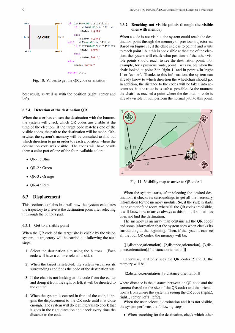
6.3.2 Reaching not visible points through the visibleones with memory
When a code is not visible, the system could reach the des-tination point through the memory of previous trajectories.Based on Figure 11, if the child is close to point 3 and wantsto reach point 1 but this is not visible at the time of the elec-tion, the system will check what positions of the other vis-ible points should reach to see the destination point. Forexample, for a previous route, point 1 was visible when thechair looked at point 2 in ’right 1’ and in point 4 in ’right1’ or ’center’. Thanks to this information, the system canalready know to which direction the wheelchair should go.In addition, the distance to the codes will be taken into ac-count so that the route is as safe as possible. At the momentthe chair has reached a point where the destination code isalready visible, it will perform the normal path to this point.
Fig. 11: Visibility map to arrive to QR code 1
When the system starts, after selecting the desired des-tination, it checks its surroundings to get all the necessaryinformation for the memory module. So, if the system startsin the center of the room, where all the QR codes are visible,it will know how to arrive always at this point if sometimesdoes not find the destination.
The memory is an array than contains all the QR codesand some information that the system sees when checks itssurrounding at the beginning. Then, if the systems can seeall the four QR codes, the memory will be:
[[1,distance,orientation], [2,distance,orientation], [3,dis-tance,orientation],[4,distance,orientation]]
Otherwise, if it only sees the QR codes 2 and 3, thememory will be:
[[2,distance,orientation],[3,distance,orientation]]
where distance is the distance between de QR code and thecamera (based on the size of the QR code) and the orienta-tion is from where the system is seeing the QR code (right2,right1, center, left1, left2).
When the user selects a destination and it is not visible,the system performs the following steps:
• When searching for the destination, check which other

Jaime Cabrera Calderon: Computer Vision System for a wheelchair for children with functional diversity 7
QR codes are visible.
• Once the system knows that the destination is not visi-ble, check which of the visible codes was closer to thesystem when the memory was filled.
• Go to the destination based on the selected point to beable to see the final destination point
• Once the desired point is reached, check again for thefinal destination point.
• Once the final QR code is detected, move to the pointas usual.
7 EXPERIMENTAL SET-UP
7.1 QR specifications
For a good detection of the codes, these must be placed on aflat surface, such as a wall. It is very important that the codeis flat, since any alteration or curve in the code can make itsdetection more inaccurate. The code is recommended tobe be attached to a harder surface, such as a cardboard, awood sheet, polyester or similar. The use of this materialis mandatory if you want to place the codes in the cornersof the room, since with this mechanism the four cornersof the code can be clamped better in the wall and it willcontinue to show itself flat. It is advisable not to plasticizethe codes since the plastic can create reflections and maymake it difficult to detect the codes. It is also mandatory toput the codes at the same height as the center of the camera.
The QR code must be created using on-line code cre-ation tools[13]. In these tools you can choose the messagethat will be displayed when the code is detected. This mes-sage must be a number from 1 to 4. The size of the codesmust be 600x600 to 1000x1000 pixels printed on a DIN-A3sheet with margins, so that its detection is the best possible.Therefore, once the code is printed, the size of its sides mustbe 26 to 28 centimetres, without including the margins.
Fig. 12: QR codes used for the experimental set-up
7.2 Variables and measures used in the proofof concept
As you can see in Figure 13, the position of the servo de-pends on the pulse value that is receiving. For the proof ofconcept the used values are the ones that are in Figure 13,where 500 is maximum left and 2500 is maximum right.
Fig. 13: Pulses values for the servo motor on the prototype
On the other hand, in Figure 14 there are the values thatthe motor controller is receiving depending on the situationof the system. Notice the speed of the motors depending onthe movement, which motors are working in every case andthe action that will be done after performing the movement.
Fig. 14: Motors behaviour for the different movements
7.3 The button pad implementationWe have created the structure using cardboard and verycheap materials to make it as cheap as possible. Check theimage of the final result of the first version in Figure 15
Fig. 15: Buttons pad first final version
See Annex 1 for more pictures about the creation processof the buttons pad.
8 RESULTS
Furthermore, in Figure 17 you can check graphically thatwhen the distance in meters gets lower, the size of the qrcode in the image from the camera is bigger.
In terms of results, the computer vision part is finishedand fully working. The system actually detects all the QRcodes that is seeing and it knows where to go according tothe destination selected by the user. The software has beenimplemented, changed and tested in the prototype to checkin real life how does the system works. Thanks to that, boththe Computer Vision System and the prototype are able toperform the required actions. The user can select a destina-tion through the button pad very simply thank to the coloursof the buttons and the colour part in the QR code, as you can

8 EE/UAB TFG INFORMATICA: Computer Vision System for a wheelchair
• Button 1 Button 2 Button 3 Button 4Key a,w,s,x t,h,g p,o,l 1,5,4,8
TABLE 1: KEYS AND BUTTONS RELATIONS.
Fig. 16: Distance values and the relation with the QR codesinformation
see in Figures 12 and 15. The system is able to scan its sur-roundings in order to fill the memory data to us it if it doesnot find the destination. When the destination is selected,the system will search for the destination and arrive at thedesired point in the approximate times that can be seen inthe Figure 18. The system check first on the front and if itdoes not find the destination, it turns back and checks again.To scan, the servo motor moves the camera to different posi-tions according to the pulses shown in Figure 13. When thedestination is detected, the robot turns to watch the destina-tion directly and starts moving to the point. If the systemis detecting the QR code from the extremes (for example,it is viewing the code from very far to the right), it will goto the front of the code to start getting closer to the desti-nation viewing the code better and in a safer way. If thesystem loses sight of the destination QR code, it will scanagain to find it and continue the route. After scanning thesecond time for a QR code, if it is not visible, the systemwill use the memory module to arrive at a point where thecode should be visible. The system is checking all the timeif it is going straight to the QR code to focus to the code ifit is necessary. Finally, when the system reaches the desti-nation, the system waits for another destination through thebuttons.
So, at this point of the project, theses are the elementsthat are already developed and working.
• A Computer Vision System that has all the func-tionalities to give autonomy to an existing electricwheelchair.
• A functional proof of concept that works and it’s goodto test and improve the Computer Visions System.
• A destination input system through a reused keyboardthat works thanks to a buttons structure. This part iscompletely finished and works perfectly.
• A memory module that can help the system to arrive todestinations that are not visible in specific situations.
Fig. 17: Graphic of the distance values and the QR codesinformation
• A system prototype with the real wheelchair and theproject implemented on it that works and have auton-omy, but that can be improved by analysing and adapt-ing both the wheelchair code and the Computer VisionSystem code.
There are differences between the proof of concept andthe prototype. In the proof of concept everything is work-ing, all modules. Despite the cheap materials and the insta-bility of the system in some movements, the proof of con-cept works as expected. On the other hand, in the proto-type, the interaction module is exactly the same, so it worksperfectly. The search module works but there are differ-ences in terms of time spent in the rotations to adapt it tothe wheelchair. The same happens with the displacementmodule, it works but some parameters have been changedto adapt them to the chair. The memory module depends onparameters form the Search and Displacement modules, sothe behaviour is not as good as in the proof of concept. Asyou can see in Figure 18, the proof of concept is faster inthe scanning because it is an smaller system and more sta-ble for the web cam, this is why it can take pictures morequickly. Otherwise, the displacement is faster in the system

Jaime Cabrera Calderon: Computer Vision System for a wheelchair for children with functional diversity 9
prototype because it has more powerful motors and it canmove faster than the proof of concept.
In Figure 16 you can notice the relation between the dis-tance between the camera and the QR codes in meters andthe information that the system is getting from the QR codesto know how close it is, the size of the QR code in pixels inthe image and the percentage that is occupying of the totalof the image. You can also compare the values with whichthe system works correctly. When the distance is within thered range, the system has reached the destination. So thesystem can work without trouble in big rooms because itdetects codes that are almost 4 meters away.
Fig. 18: Time spent by each system in performing thesearch and displacement actions
We have uploaded a video of the wheelchair performingthe search of the destination and the displacement4
9 DISCUSSION
Based on the purpose and the main objectives of the projectand the final results, there is enough evidence and good re-sults to conclude that the result of the project has been suc-cessful. All the main objectives and some improvements ofthe original concept have been fulfilled, such as:
• Implement the system to work as a module than can beplugged very simply in the wheelchair
• Design and implement a low cost button pad that fol-lows the philosophy of low price and social purpose ofboth projects, the wheelchair and the computer visionsystem.
• Implement a proof of concept to test and develop thesystem rather than asking for a real wheelchair.
• Implement an optional memory module to make thesystem more intelligent and efficient.
According to the results mentioned before, we come tothe conclusion that the system can work without trouble inbig rooms because it can detect QR codes that are almost 4meters away. This distance is good enough to accomplishthe purpose of the project. On the other hand, the time thatthe wheelchair spend in searching and reaching the destina-tions is quite good, but it can be improved by checking andmodifying the wheelchair’s code to make it more adapted toour system and creating a more stable base for the web cam.With all these points fulfilled, it is concluded that the projecthas been successful and that it opens up to be improved tobecome a successful system that helps children with specialneeds giving them more autonomy and security in order tomake them happier.
4https://youtu.be/VqULQrx76ow
10 CONCLUSIONS
Looking back to the main objectives of the project and com-paring with the results, we can say that we have a systemthat satisfactorily satisfies the children’s need to move au-tonomously through a room thanks to a very robust searchmodule that cant locate the wheelchair among all the QRcodes to finally arrive at desired point in a short period oftime. On the other hand, the buttons pad is very useful andfulfils its objective the whole time, in addition to being avery economical and solvent solution. One of the strongestpoints of the project is that these functional system works asa unique module that can be plugged in the wheelchair verysimply without having to modify any intern thing, just placeit and connect it through bluetooth. Moreover, the user willfeel very comfortable in the wheelchair using this systembecause the movements are smooth and the execution timesare very reasonable.
11 FUTURE WORK
The next steps are continue working on the integration ofthe system in the wheelchair in order to make it as comfort-able as possible for the children. The memory module canbe improved as well to save more information of differentmoments to use it when necessary. Also we will work onthe implementation of a system that work with images in-stead of QR codes in order to make the system more userfriendly. To finish, we will try to get a 360 degree servomotor to make the system more comfortable and we willtry to adjust the parameters more for a perfect operation.
12 ACKNOWLEDGEMENTS
I like acknowledge to Nexe Fundacio for making us get theidea of the need to make this system and for trusting us todevelop it and make it possible. I would also like to thankyou for having left us the original wheelchair to be able toimplement the system, as well as offering us all the infor-mation we have needed throughout the development.
I would like to thank David Garcia for giving us all thenecessary information about service learning and introduceus into this way of learning while carrying out projects withsocial impact. Thank also my tutor, Fernando Vilarino forhelping me during all the project and for his enthusiasmand dedication. Seeing your enthusiasm about the projecthas made me more eager to do my best and your advice hasmade me take the project to another level.
Para finalizar me gustarıa agradecer a mi familia por suapoyo constante durante el desarrollo del proyecto y durantetoda la carrera. Me ayudais a plantar las semillas de todasmis ideas y me acompanais mientras los frutos crecen. Estoes gracias a mi hermana Cristina, mi madre Cleopatra y mipadre Joaquın.

10 EE/UAB TFG INFORMATICA: Computer Vision System for a wheelchair
REFERENCES
[1] Sustainable Development Goalshttps://www.un.org/sustainabledevelopment/sustainable-development-goals/
[2] UAB - Aprenentage Servei (Service Learning)http://pagines.uab.cat/aps/ca
[3] McMillan, Janice and Goodman, Suki and Schmid,Barbara; Illuminating “Transaction Spaces” in HigherEducation: University–Community Partnerships andBrokering as “Boundary Work”Journal of Higher Education Outreach and Engage-menthttps://www.rs-online.com/designspark/lidar-radar-digital-cameras-the-eyes-of-autonomous-vehicles
[4] Romero, David Garcia and Lalueza, Jose Luis;Procesos de Aprendizaje en Aprendizaje-ServicioUniversitario: Una Revision TeoricaJournal of Higher Education Out-reach and Engagement https://www.rs-online.com/designspark/lidar-radar-digital-cameras-the-eyes-of-autonomous-vehicles2019
[5] Silla exploradorahttp://www.sillaexploradora.es/
[6] Nexe Fundaciohttp://www.nexefundacio.org
[7] Youtube - How Google’s Self-Driving Car Workshttps://www.youtube.com/watch?v=YXylqtEQ0tk
[8] Waymo; Youtube - Waymo 360o Experience: A FullySelf-Driving Journeyhttps://www.google.es/url?sa=t&rct=j&q=&esrc=s&source=web&cd=1&cad=rja&uact=8&ved=2ahUKEwjHoNeowdvgAhXFxoUKHfRoDDoQwqsBMAB6BAgFEAQ&url=https%3A%2F%2Fwww.youtube.com%2Fwatch%3Fv%3DB8R148hFxPw&usg=AOvVaw0rR_mTMhPAiv7Nl5kLiKmo
[9] Bill Marshall; Lidar, Radar and Digital Cameras: theEyes of Autonomous Vehicleshttps://www.rs-online.com/designspark/lidar-radar-digital-cameras-the-eyes-of-autonomous-vehiclesFebruary 21, 2018.
[10] Daniel Lynn Larner, Jared Stephen Russell ; Methodand system for determining and dynamically updatinga route and driving style for passenger comfort(Google Patents)https://patents.google.com/patent/US10107635B2/enAugust 19, 2016
[11] Adrian Kaehler, Gary Bradski. Learning OpenCV:Computer Vision with the OpenCV Library. (English)O’Reilly Media, September 24, 2008.
[12] Jan Erik Solem. Programming Computer Vision withPython: Tools and algorithms for analyzing images.(English) O’Reilly Media, June 29, 2012.
[13] QR code generator online toolqr-code-generator.com
[14] Mattheieu Napoli; Looking for ways for a robot tolocate itself in the househttps://stackoverflow.com/questions/6520570/looking-for-ways-for-a-robot-to-locate-itself-in-the-house
[15] Wikipedia - Field of View / Camp de visiohttps://ca.wikipedia.org/wiki/Angle_de_visi%C3%B3
[16] PYZBAR, Python libraryhttps://www.pydoc.io/pypi/pyzbar-0.1.6/
[17] Best cameras for Computer Visionhttps://www.chiefdelphi.com/
[18] Car chasis, motor controller and cables links - Ama-zonamazon.es/car/chasisamazon.es/motor/controlleramazon.es/cables

Jaime Cabrera Calderon: Computer Vision System for a wheelchair for children with functional diversity 11
Annex 1: Images of the cre-ation process of the button pad
Fig. 19: Keyboard button structure process example
Annex 2: Sequence diagram of the software
Fig. 20: Sequence Diagram of the software