computer networks - network layer1 the network layer n design issues n routing algorithms n...
Post on 19-Dec-2015
231 views
TRANSCRIPT
Computer Networks - Network Layer 1
The Network Layer
Design Issues Routing Algorithms Congestion Control Internetworking Example Network Layer Protocols

Computer Networks - Network Layer 2
Goals of the Network Layer
The network layer is concerned with getting packets from the source all the way to the destination
the network layer must know the topology of the communication subnet choose route to avoid overloading some of the commun
ication lines and routers while leaving others idle deal with problems when the source and destination are
in different networks

Computer Networks - Network Layer 3
Services Provided to the Transport Layer Connectionless (unreliable) services
each packet must carry the full destination address no packet ordering and flow control should be done
Connection-oriented (reliable) services a network layer process on the sending site must set up a
connection to its peer on the receiving side when a connection is set up, two processes can enter a
negotiation about service parameters packets are delivered in sequence flow control is provided automatically
Computer Networks - Network Layer 4
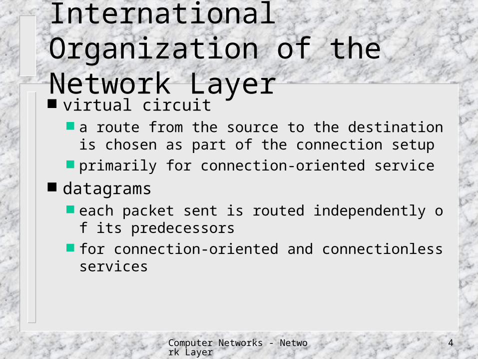
International Organization of the Network Layer virtual circuit
a route from the source to the destination is chosen as part of the connection setup
primarily for connection-oriented service datagrams
each packet sent is routed independently of its predecessors
for connection-oriented and connectionless services
Computer Networks - Network Layer 5
Datagram Vs. Virtual Circuit
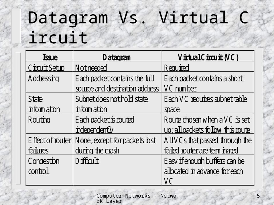
Issue Datagram Virtual Circuit (VC)Circuit Setup Not needed RequiredAddressing Each packet contains the full
source and destination addressEach packet contains a shortVC number
Stateinformation
Subnet does not hold stateinformation
Each VC requires subnet tablespace
Routing Each packet is routedindependently
Route chosen when a VC is setup; all packets follow this route
Effect of routerfailures
None, except for packets lostduring the crash
All VCs that passed through thefailed router are terminated
Congestioncontrol
Difficult Easy if enough buffers can beallocated in advance for eachVC
Computer Networks - Network Layer 6
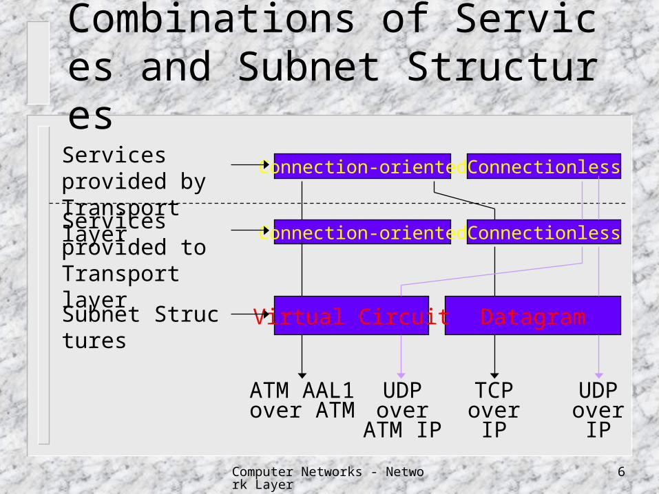
Combinations of Services and Subnet Structures
Connection-oriented Connectionless
DatagramVirtual Circuit
Services provided to Transport layer
Subnet Structures
Connection-oriented ConnectionlessServices provided by Transport layer
TCPoverIP
UDPoverIP
UDPover
ATM IP
ATM AAL1over ATM

Computer Networks - Network Layer 7
Routing
Packets are often routed from the source to the destination hop by hop.
Two networks are connected by at least a router. The network is defined from the point of view of the network layer.
Computer Networks - Network Layer 8
Types of Routing
Static Routing Routes to destinations are predetermined and are not
dependent on the current state (traffic, topology etc.) of the network.
Dynamic Routing (Adaptive Routing) Routes being learned via exchange of routing information
to reflect changes in the topology and traffic.
Default Routing: Traffic to destinations that are unknown to the router is
sent to a default “outlet”.
Computer Networks - Network Layer 9
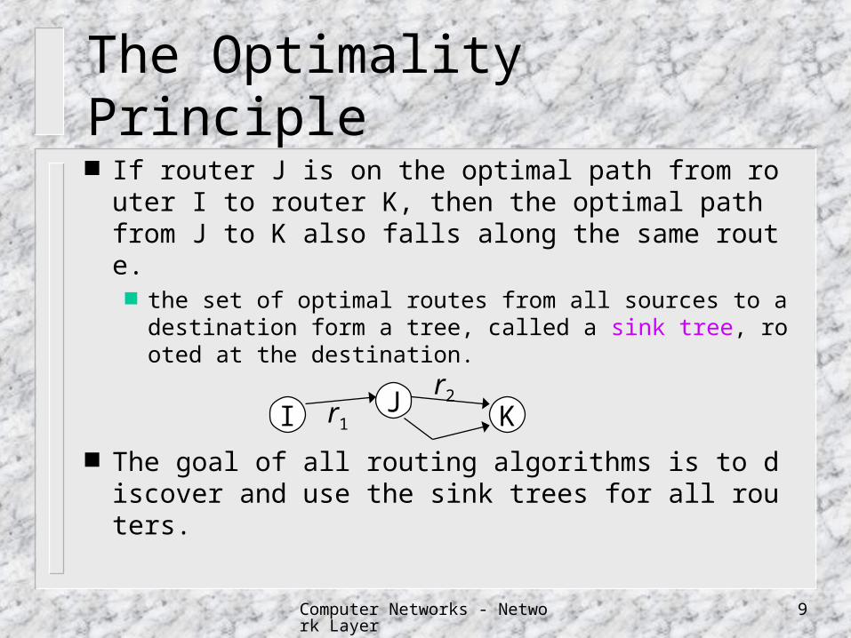
The Optimality Principle
If router J is on the optimal path from router I to router K, then the optimal path from J to K also falls along the same route.
the set of optimal routes from all sources to a destination form a tree, called a sink tree, rooted at the destination.
The goal of all routing algorithms is to discover and use the sink trees for all routers.
I J Kr1
r2
Computer Networks - Network Layer 10
Routing Algorithms
Static Routing Algorithms Shortest Path Routing Flooding Flow-Based Routing
Dynamic Routing Algorithms Distance Vector Routing Link State Routing
Hierarchical Routing Routing for Mobile Hosts Broadcast Routing Multicast Routing
Computer Networks - Network Layer 11
Shortest Path Routing
Find the shortest path between a given pair of routers.
Cost of a link may be a function of the distance, bandwidth, average traffic, communication cost, mean queue length, delay, etc.
The Dijkstra’s algorithm is used.

Computer Networks - Network Layer 12
Flooding
Every incoming packet is sent out on every outgoing line except the one it arrived on.
Vast numbers of duplicate packets are generated.
For robustness Application:
Concurrent updates of databases Always choose the shortest path
I J
K L
M
Computer Networks - Network Layer 13
Flow-Based Routing
For a given line, if the capacity and average flow are known in advance, it is possible to compute the mean packet delay on that line from queueing theory.
The routing problem then reduces to finding a routing algorithm that produces the minimum average delay for the subnet.
Computer Networks - Network Layer 14
Distance Vector Routing
RIP, the distributed Bellman-Ford routing algorithm, the Ford-Fulkerson algorithm
Each router maintains a routing table giving the best known distance to each destination and which line to use to get there.
These tables are updated by exchanging information with the neighbors.
Computer Networks - Network Layer 15
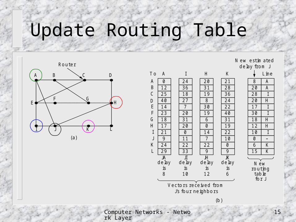
Update Routing Table
(a)
A B C D
E
I J K L
F GH
Ro uter
012254014231817219
2429
243618277
2031200
112233
2031198
301960
147
229
2128362422403119221009
8202820173018121006
15
AAI
HII
HHIKK
T o A I H K L ine
N ew estim ateddelay fro m J
ABCDEFGHIJKL
JA JI JH JKdelay delaydelaydelay
is is is is8 10 12 6
N ewro uting
tab lefo r J
V ecto rs received fro mJ's fo ur neighbo rs
(b)
Computer Networks - Network Layer 16
Distance Vector Routing
Metric used to measure the “distance” number of hops time delay queue length
Drawback it reacts rapidly to good news, but leisurely to
bad news.

Computer Networks - Network Layer 17
Count-to-Infinity Problem
1
1 2
1 2 3
1 2 3 4
A B C D E
Good News
down initially andcome up later
1 2 3 4
3 2 3 4
3 4 3 4
5 4 5 4
5 6 5 6
7 6 7 6
7 8 7 8
A B C D E
Bad News
Initially
After 1 exchange
After 2
exchanges
After 3
exchanges
After 4
exchanges
After 5
exchanges
After 6
exchanges
alive initially anddown later
Computer Networks - Network Layer 18
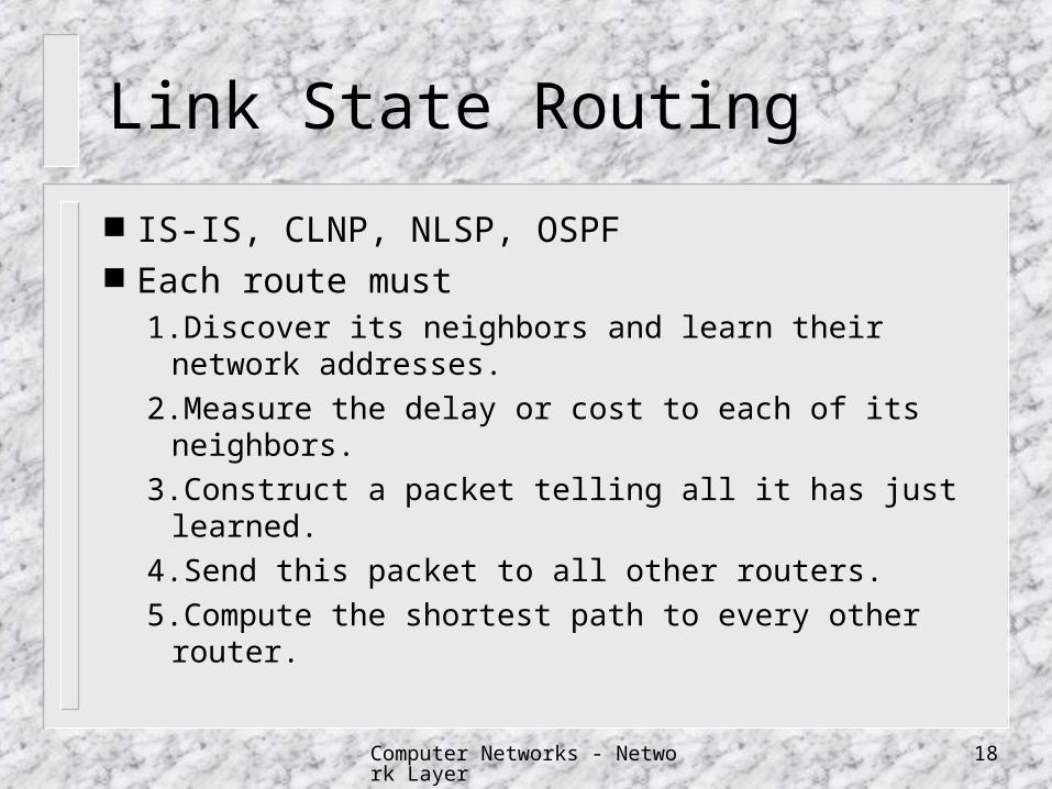
Link State Routing
IS-IS, CLNP, NLSP, OSPF Each route must
1.Discover its neighbors and learn their network addresses.
2.Measure the delay or cost to each of its neighbors.
3.Construct a packet telling all it has just learned.
4.Send this packet to all other routers.
5.Compute the shortest path to every other router.

Computer Networks - Network Layer 19
Learning About the Neighbors
Send a special HELLO packet on each point-to-point line
the router on the other end is expected to send back a reply telling who it is
I J
K
L
HELLO
I am J
Computer Networks - Network Layer 20
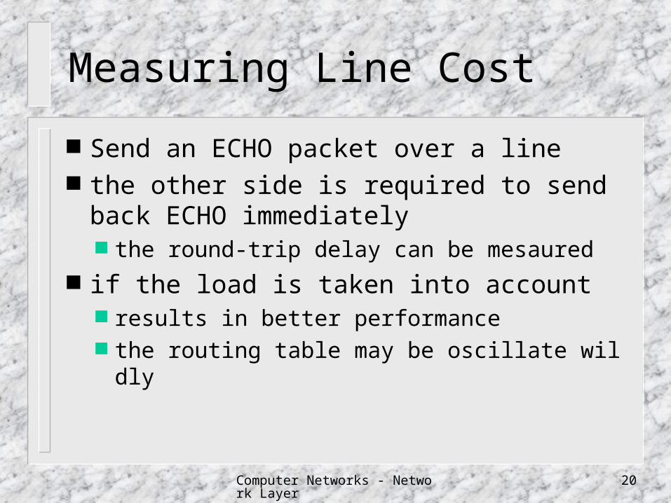
Measuring Line Cost
Send an ECHO packet over a line the other side is required to send back ECH
O immediately the round-trip delay can be mesaured
if the load is taken into account results in better performance the routing table may be oscillate wildly
Computer Networks - Network Layer 21
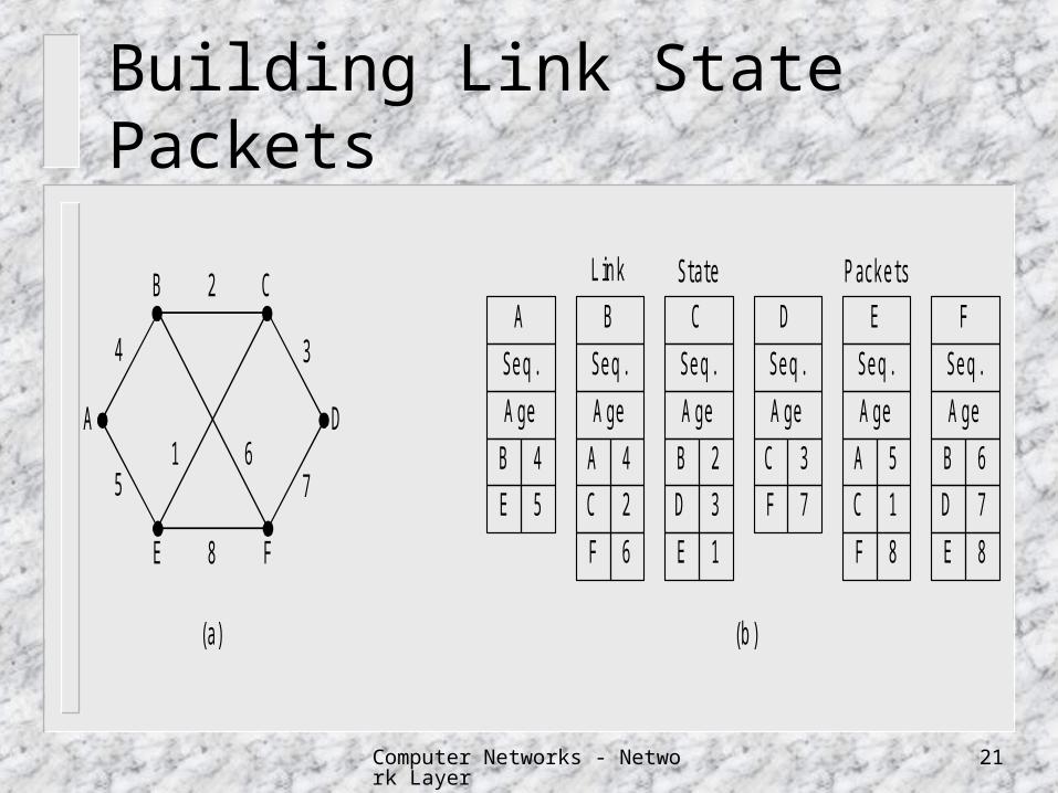
Building Link State Packets
B C
E F
A D61
2
8
5 7
4 3
(a)
A
Seq.
A ge
B C D E F
B 4
E 5
Seq.
A ge
A 4
C 2
Seq.
A ge
B 2
D 3
Seq.
A ge
C 3
F 7
Seq.
A ge
A 5
C 1
Seq.
A ge
B 6
D 7
F 6 E 1 F 8 E 8
L ink State P ackets
(b)
Computer Networks - Network Layer 22
Distributing Link State Packets
Use flooding sequence number is used to determine among
new, duplicate, or obsolete packets three problems
sequence number may wrap around a crash router will lose track of its sequence number
when it restarts a corrupted bit in sequence number may cause
disaster
Computer Networks - Network Layer 23
The Use of ‘Age’ Field
Include in each packet decremented once per second when the age hits zero, the information fro
m that router is discarded also decremented by each router during the
initial flooding process no packet can get lost and live for an indefinite
period of time
Computer Networks - Network Layer 24
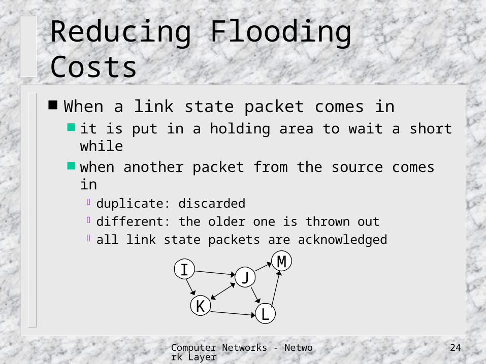
Reducing Flooding Costs
When a link state packet comes in it is put in a holding area to wait a short while when another packet from the source comes in
duplicate: discarded different: the older one is thrown out all link state packets are acknowledged
I J
K L
M
Computer Networks - Network Layer 25
Computing the New Route
Once a router has accumulated a full set of link state packets it can construct the entire subnet graph by locall
y running Dijkstra’s algorithm for a subnet with n routers, each of which h
as k neighbors, the memory required to store the input data is proportional to kn.
Computer Networks - Network Layer 26
Hierarchical Routing
When hierarchical routing is used, the routers are divided into regions each router knows all the details about how to
route packets to destinations within its own region
each router knows nothing about the internal structure of other regions.

Computer Networks - Network Layer 27
Hierarchical RoutingRegion 1 Region 2
Region 5
A
BC
AB
CD
Region 3Region 4
A
BA
B
C
A
B CD
Full table for 1A
Dest. Line Hops1A ---- ---1B 1B 11C 1C 12A 1B 22B 1B 32C 1B 32D 1B 43A 1C 33B 1C 24A 1C 34B 1C 44C 1C 45A 1C 45B 1C 55C 1B 55D 1C 5
Dest. Line Hops1A ---- ---1B 1B 11C 1C 12 1B 23 1C 24 1C 35 1C 4
Hierarchicaltable for 1A
Computer Networks - Network Layer 28
Routing for Mobile Hosts
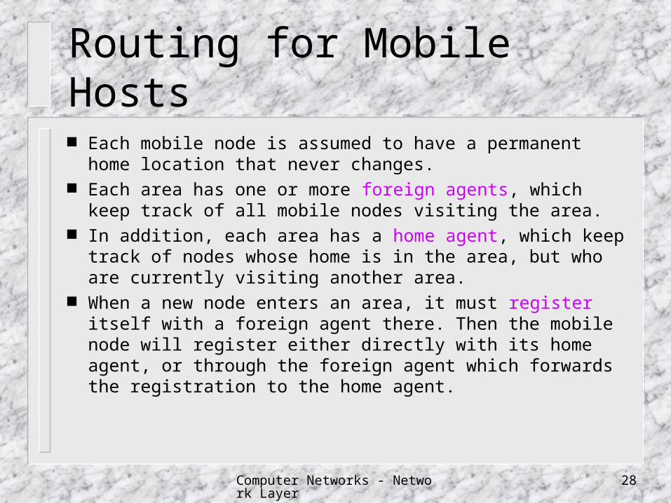
Each mobile node is assumed to have a permanent home location that never changes.
Each area has one or more foreign agents, which keep track of all mobile nodes visiting the area.
In addition, each area has a home agent, which keep track of nodes whose home is in the area, but who are currently visiting another area.
When a new node enters an area, it must register itself with a foreign agent there. Then the mobile node will register either directly with its home agent, or through the foreign agent which forwards the registration to the home agent.
Computer Networks - Network Layer 29
Routing for Mobile Hosts
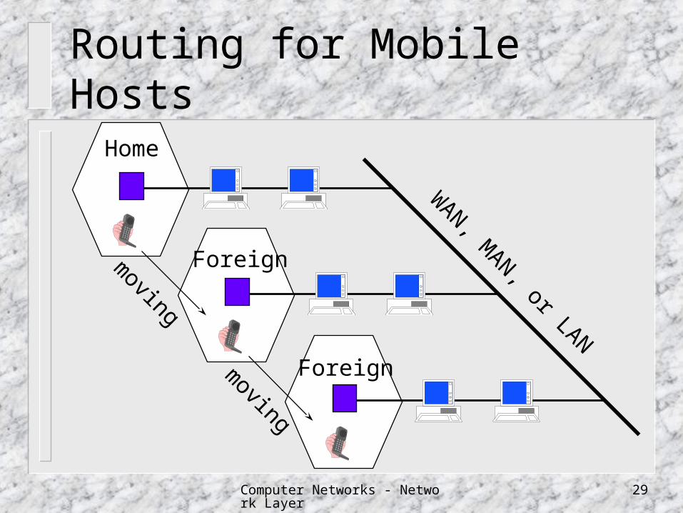
Home
WAN, M
AN, or LAN
Foreign
Foreign
moving
moving
Computer Networks - Network Layer 30
Routing for Mobile Hosts
Datagrams sent to the mobile node are intercepted by its home agent, then tunneled by the home agent towards the mobile
node, received at the tunnel foreign agent, and finally delivered to the mobile node.

Computer Networks - Network Layer 31
Routing for Mobile Hosts
1. Packet is sent to the mobile host’s home
2. Packet is tunneled to the foreign agent
3. Sender is given foreign agent’s address
4. Subsequent packets are tunneled to the foreign agent
Computer Networks - Network Layer 32
Broadcast Routing
To simply send a distinct packet to each destination
Flooding Multidestination Routing Spanning Tree Routing Reverse Path Forwarding

Computer Networks - Network Layer 33
Multidestination Routing
Each packet contains a list of desired destinations. When a packet arrives, the router checks all the
destinations to determine the set of output lines for forwarding the packet. An output line is selected if it is the best route to at least one of the destinations.
The router generates a new copy of the packet for selected output line, with a set of destinations that are to use the line.
Computer Networks - Network Layer 34
Spanning Tree Routing
Assume each router has knowledge of a spanning tree (e.q. a sink tree) in the network.
Each router copies an incoming broadcast packet onto all the spanning tree lines except the one it arrives on.
Use minimum number of packets.
Computer Networks - Network Layer 35
Reverse Path Forwarding
Without knowing any spanning tree
if a packet arrives at the line that is normally used for sending packets to the source of the broadcastthe router forwards copies of it onto all lines
except the one it arrived on.
otherwisethe packet is discarded
Computer Networks - Network Layer 36
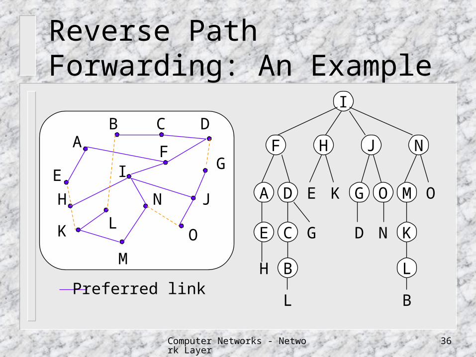
Reverse Path Forwarding: An Example
AB C
F
D
G
J
O
IE
H
K L
M
N
I
F NJH
A MGED OOK
E KDGC N
H LB
BLPreferred link
Computer Networks - Network Layer 37
Multicasting
Send a message to all the other members of the group
group management create and destroy groups for processes to join and leave groups
routers knows which of their hosts belong to which group
routers tell their neighbors, so the information propagates through the subnet

Computer Networks - Network Layer 38
Multicast Routing
Each router computes a spanning tree covering all other routers in the subnet.
When a multicast packet for a group arrives, the first router examines its spanning tree and prunes it, removing all lines that do not lead to hosts in the group.
Multicast packets are forwarded only along the pruned tree.
mn trees is needed with n groups, each with an average of m members.

Computer Networks - Network Layer 39
Core-based Tree for Multicast Routing A single spanning tree,called core-based
tree, for a group is computed, with the root (core) near the middle of the group.
A host first sends a multicasting message to the core, which then does the multicasting along the spanning tree.
The tree is not optimal. However only n trees need to be stored.
Computer Networks - Network Layer 40
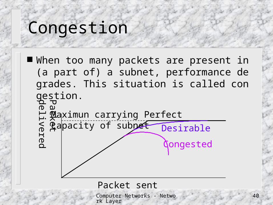
Congestion
When too many packets are present in (a part of) a subnet, performance degrades. This situation is called congestion.
Packet
delivered
Packet sent
Maximun carryingcapacity of subnet
Perfect
Desirable
Congested
Computer Networks - Network Layer 41
Congestion Control
goal make sure the subnet is able to carry the offered
traffic Congestion causes
bursty data insufficient memory slow processor low-bandwidth line

Computer Networks - Network Layer 42
Flow Control vs. Congestion Control
1 Gbps
1000 GbpsPC
SuperComputer
100 Kbps
1 Mbps 1000
1000
FlowControl
CongestionControl
Computer Networks - Network Layer 43
General Principles
Open Loop make sure congestion does not occur in the first
place Closed Loop
monitor the system to detect congestion (where and when)
pass this information to places where action can be taken
adjust system operation to correct the problem

Computer Networks - Network Layer 44
Congestion Control Algorithm Taxonomy explicit feedback
Packets are sent back from the point of congestion to warn the source.
implicit feedback The source deduces the existence of congestion
by making local observations, such as the acknowledgement time.
Computer Networks - Network Layer 45
Congestion Prevention Policies
Virtual circuit versus datagram Most algorithms work only with virtual circuit.
Packet queueing and service policy input queueing versus output queueing round robin, priority-based, random, ...
Packet discarded policy which packet is dropped when there is no space
Routing algorithm Load sharing
Packet lifetime management
Computer Networks - Network Layer 46
Traffic Shaping/Policing
Congestion would be less common if traffic is less bursty
traffic shaping force packets to be transmitted at a more predic
table rate traffic policing
monitor a traffic flow
Computer Networks - Network Layer 47
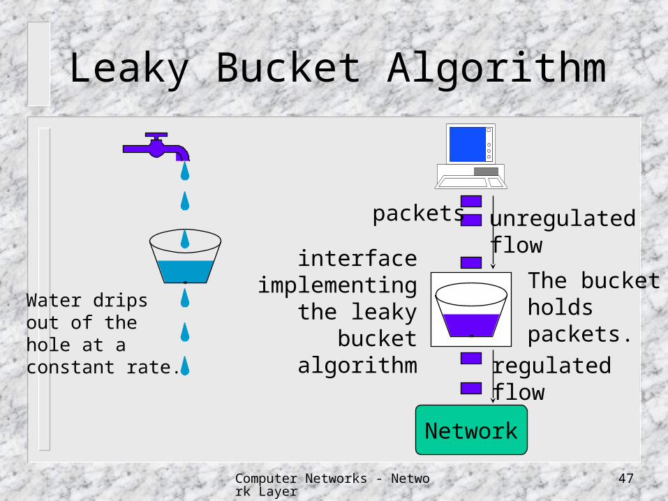
Leaky Bucket Algorithm
Water dripsout of thehole at aconstant rate.
Network
packets
regulatedflow
unregulatedflow
interfaceimplementing
the leakybucket
algorithm
The bucketholdspackets.
Computer Networks - Network Layer 48
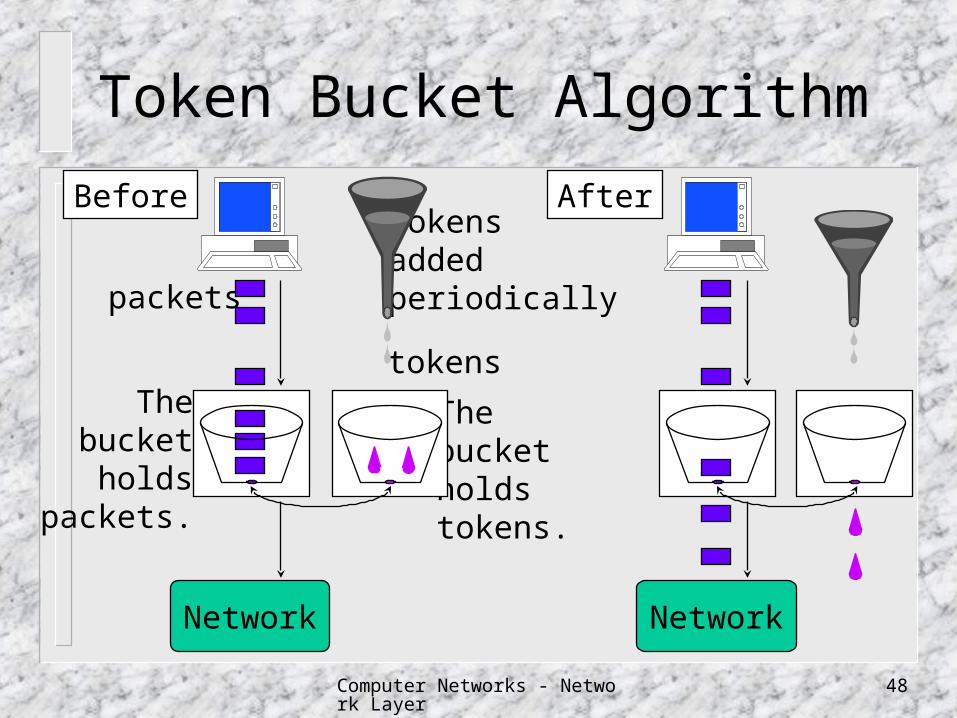
Token Bucket Algorithm
Before
tokens
packets
Thebucketholdstokens.
Thebucket
holdspackets.
tokensaddedperiodically
After
NetworkNetwork
Computer Networks - Network Layer 49
Properties of Token Bucket
allows saving up permission to send large bursts later
throws away token when the bucket fills up but never discards packets
C: token bucket capacity; :token arrival rate; S: burst length; M: maximal output rate
C+ S=MS
Computer Networks - Network Layer 50
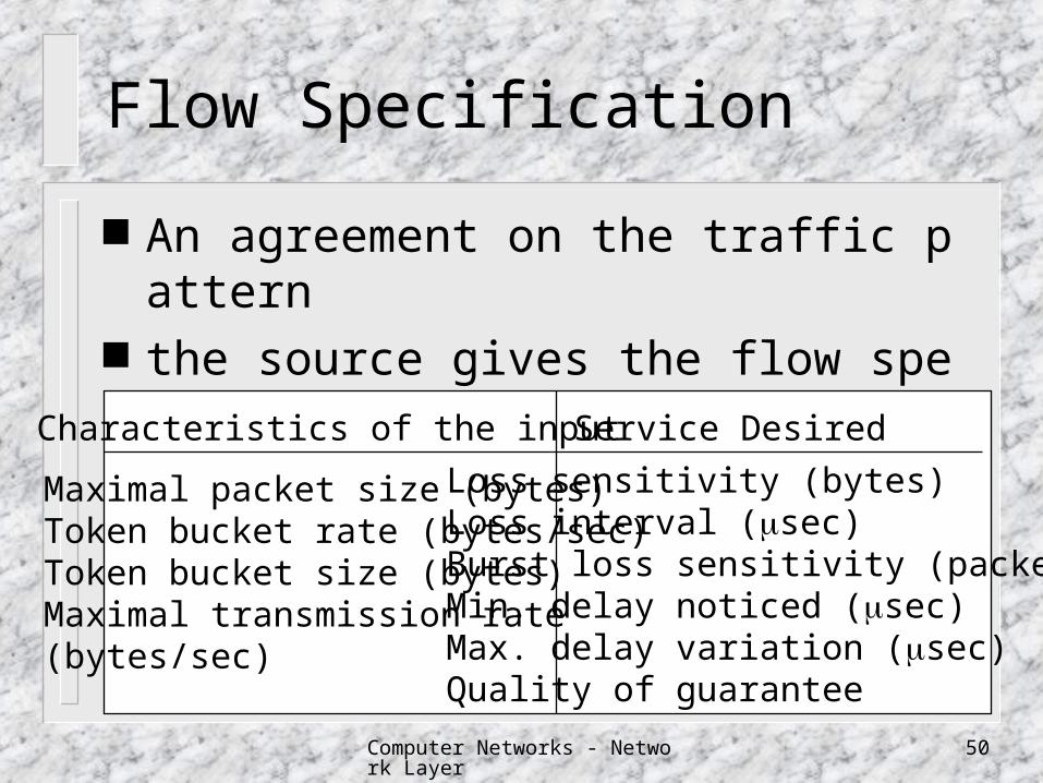
Flow Specification
An agreement on the traffic pattern the source gives the flow specification to th
e subnet for approval
Maximal packet size (bytes)Token bucket rate (bytes/sec)Token bucket size (bytes)Maximal transmission rate(bytes/sec)
Characteristics of the input Service Desired
Loss sensitivity (bytes)Loss interval (sec)Burst loss sensitivity (packets)Min. delay noticed (sec)Max. delay variation (sec)Quality of guarantee
Computer Networks - Network Layer 51
Congestion Control in Virtual Circuit Subnets Admission control
once congestion has been signaled, no more virtual circuits are set up until the problem has gone away
carefully route all new virtual circuits around problem areas
negotiate an agreement between the host and subnet when a virtual circuit is set up

Computer Networks - Network Layer 52
Choke Packets
5
7
21 3
46
Heavyflow
Choke
Choke
ChokeReducedflow
Flow is reduced.

Computer Networks - Network Layer 53
Hop-by-Hop Choke Packets
5
21 3
4
Heavyflow
Choke
Choke
Choke
Reduc
ed
flow
Flow is reduced.
To provide quickrelief at the pointof congestion atthe price of usingup more buffersupstream.
Computer Networks - Network Layer 54
Load Shedding
when routers are being inundated by packets that they can not handle, they just throw them away.
Packet discarding policy Wine: Old is better than new. Milk: New is better than old. Priority Control

Computer Networks - Network Layer 55
Jitter Control The jitter is the amount of variation in the end-to-end
packet transit time. The jitter can be bounded by computing the expected
transit time for each hop along the path. When a packet arrives at a router, the router checks to see how much the packet is behind or ahead of its schedule. This information is stored in the packet and updated at each hop. If the packet is ahead of schedule, it may be held just enough to get it back on schedule. If it is behind schedule, the router tries to get it out the door quickly.
Computer Networks - Network Layer 56
Congestion Control for Multicasting Multicast flows from multiple sources to m
ultiple destinations (cable television) if it is the sender that reserves bandwidth
each sender should track membership changes regenerate the spanning tree at each change
RSVP (Resource reSerVation Protocol) it is the receiver that reserves bandwidth
Computer Networks - Network Layer 57
RSVP (Resource reSerVation Protocol) allows multiple senders to transmit multiple
groups of receivers. permits individual receivers to switch
channels freely. optimizes bandwidth use while at the same
time eliminating congestion. uses multicast routing using spanning trees

Computer Networks - Network Layer 58
Multicast Spanning Trees
Senders
Receivers
1 2
3 4 5
1 2
3 4 5
1 2
3 4 5
Multicast spanningtree for host 2
Multicast spanningtree for host 1
Computer Networks - Network Layer 59
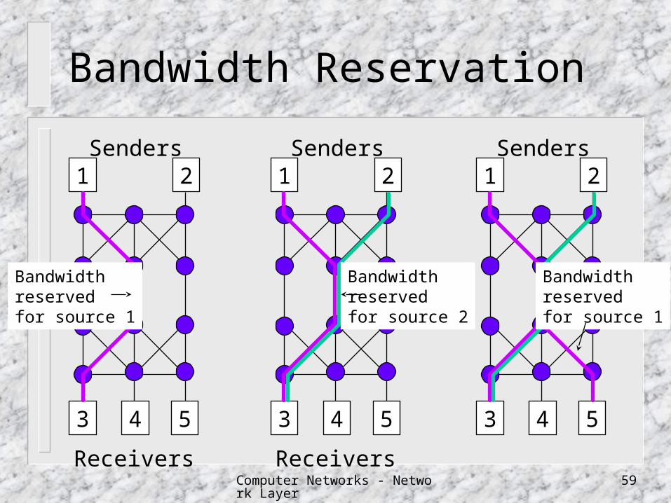
Bandwidth Reservation
Senders
Receivers
1 2
3 4 5
Senders
Receivers
1 2
3 4 5
Senders1 2
3 4 5
Bandwidthreservedfor source 1
Bandwidthreservedfor source 1
Bandwidthreservedfor source 2
Computer Networks - Network Layer 60
RSVP (Resource reSerVation Protocol) When making a reservation, a receiver can
(optionally) specify one or more sources that it wants to receive from.
It can also specify whether these choices are fixed for the duration of the reservation, or whether the receiver wants to keep open the option of changing sources later.
Computer Networks - Network Layer 61
RSVP (Resource reSerVation Protocol) Two receivers are only set up to share a
path if they both agree not to change sources later on.
Once a receiver has reserved bandwidth, it can switch to another source and keep that portion of the existing path that is valid for the new source.

Computer Networks - Network Layer 62
X.25
Internetworking
B
802.4 LAN802.3 LAN
802.5 LAN
R
DECnet
R
SNA
R
R
Computer Networks - Network Layer 63
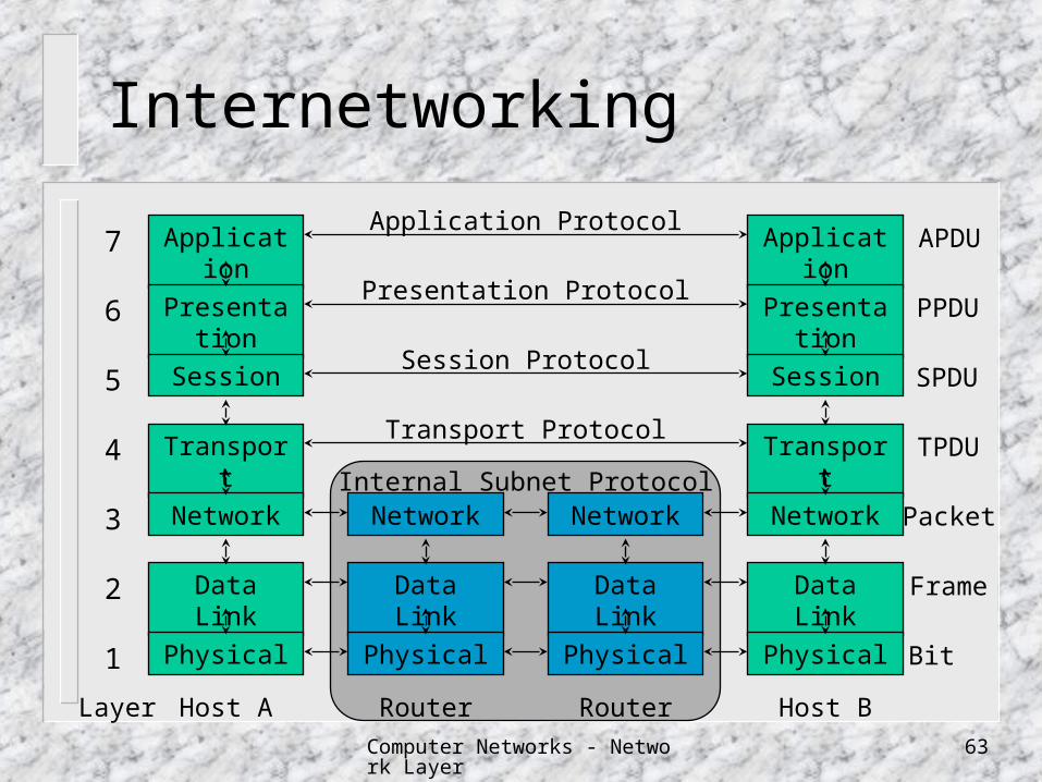
Internetworking
Application
Presentation
Session
Transport
Network
Data Link
Physical
Application
Presentation
Session
Transport
Network
Data Link
Physical
7
6
5
4
3
2
1
Layer
APDU
PPDU
SPDU
TPDU
Packet
Frame
Bit
Application Protocol
Presentation Protocol
Session Protocol
Transport Protocol
Host A Host B
Network
Data Link
Physical
Network
Data Link
Physical
Router Router
Internal Subnet Protocol
Computer Networks - Network Layer 64
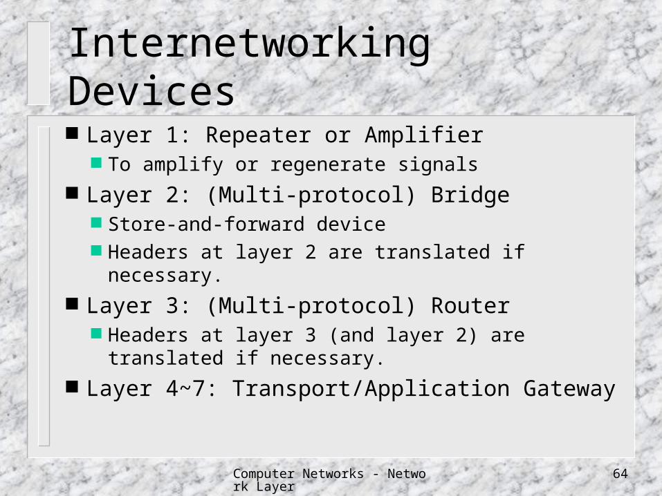
Internetworking Devices
Layer 1: Repeater or Amplifier To amplify or regenerate signals
Layer 2: (Multi-protocol) Bridge Store-and-forward device Headers at layer 2 are translated if necessary.
Layer 3: (Multi-protocol) Router Headers at layer 3 (and layer 2) are translated if
necessary. Layer 4~7: Transport/Application Gateway
Computer Networks - Network Layer 65
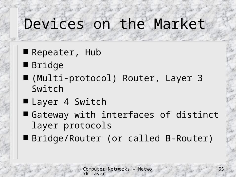
Devices on the Market
Repeater, Hub Bridge (Multi-protocol) Router, Layer 3 Switch Layer 4 Switch Gateway with interfaces of distinct layer
protocols Bridge/Router (or called B-Router)
Computer Networks - Network Layer 66
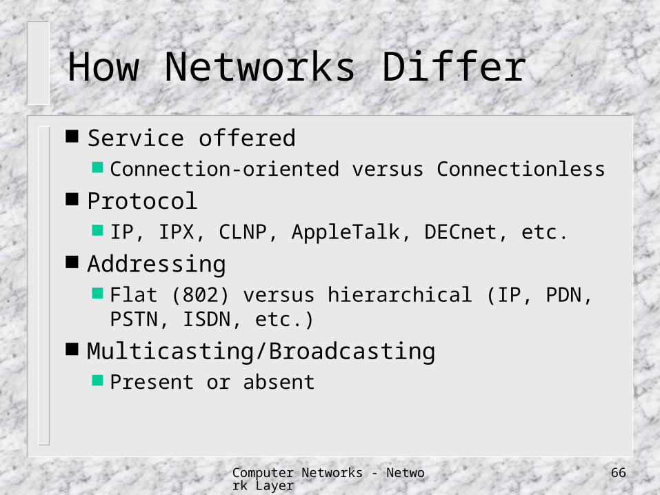
How Networks Differ
Service offered Connection-oriented versus Connectionless
Protocol IP, IPX, CLNP, AppleTalk, DECnet, etc.
Addressing Flat (802) versus hierarchical (IP, PDN, PSTN, ISDN, e
tc.) Multicasting/Broadcasting
Present or absent
Computer Networks - Network Layer 67
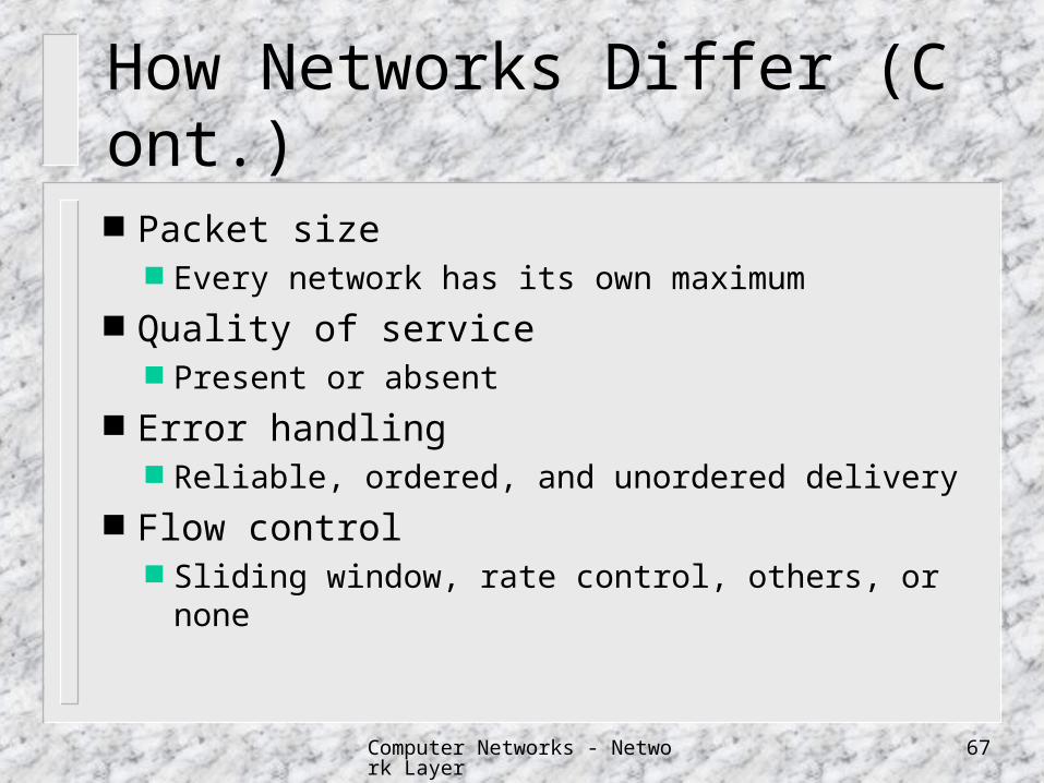
How Networks Differ (Cont.)
Packet size Every network has its own maximum
Quality of service Present or absent
Error handling Reliable, ordered, and unordered delivery
Flow control Sliding window, rate control, others, or none

Computer Networks - Network Layer 68
How Networks Differ (Cont.)
Congestion control Leaky bucket, choke packets, etc.
Security Privacy rules, encryption, etc.
Parameters Different timeouts, flow specifications, etc.
Accounting By connection time, by packet, by byte, or not at all
Computer Networks - Network Layer 69
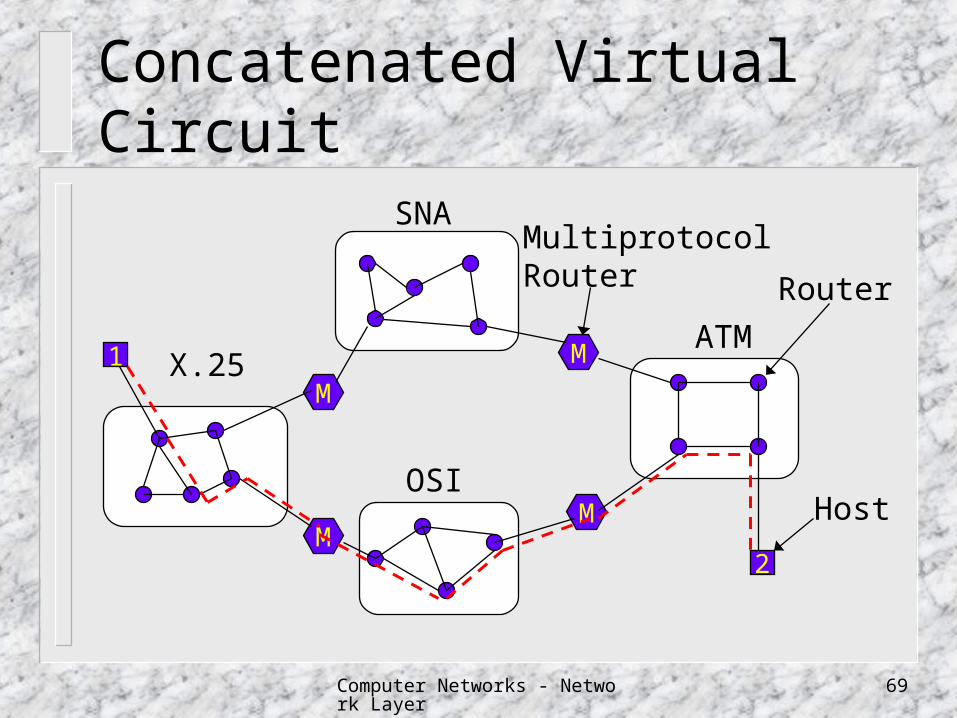
Concatenated Virtual Circuit
1
M
M
M
M
2
SNA
OSI
X.25ATM
Router
Host
MultiprotocolRouter
Computer Networks - Network Layer 70
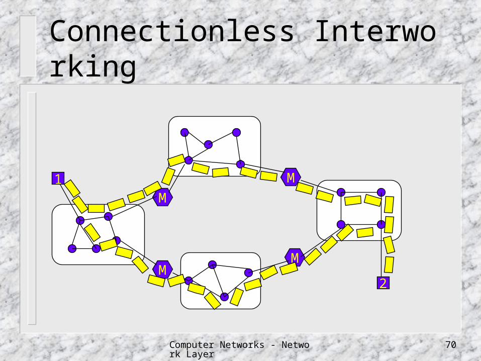
Connectionless Interworking
1
M
M
M
M
2
Computer Networks - Network Layer 71
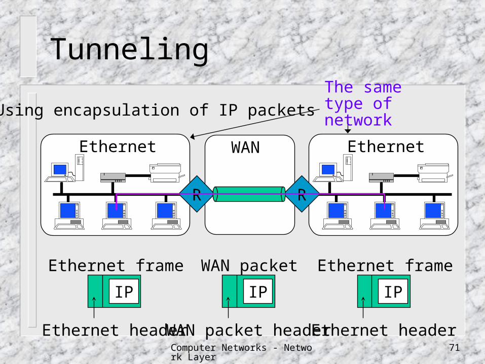
Tunneling
EthernetEthernet
RR
WAN
IP
Ethernet header
Ethernet frame
IP
WAN packet header
WAN packet
IP
Ethernet header
Ethernet frame
Using encapsulation of IP packets
The same type of network
Computer Networks - Network Layer 72
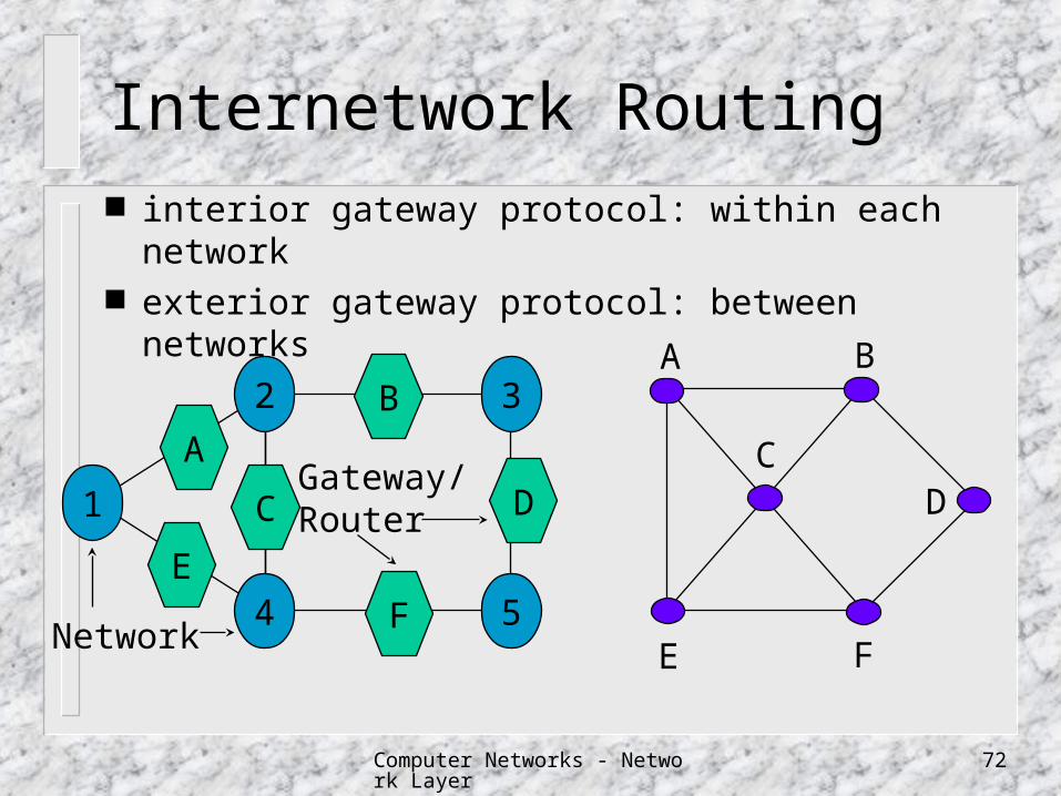
Internetwork Routing interior gateway protocol: within each network exterior gateway protocol: between networks
Network
1
2 3
4 5
A
B
C D
E
F
Gateway/Router
A
E
C
B
D
F
Computer Networks - Network Layer 73
Autonomous System (AS)
An autonomous system is a set of routers having a single routing policy, running under a single technical administration.
Each AS is independent of all the others.
Computer Networks - Network Layer 74
Fragmentation and Reassembly
Each network imposes some maximum size on its packets
When a large packet wants to travel through a network whose maximum packet size is too small allow gateway to break packets up into
fragments fragments are reassembled into packet latter
Computer Networks - Network Layer 75
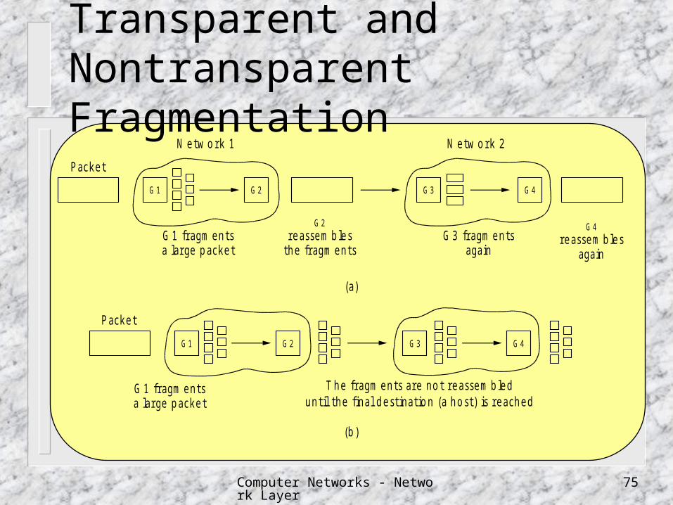
Transparent and Nontransparent Fragmentation
G 1 G 2 G 3 G 4
G 1 G 2 G 3 G 4
P acket
N etw o rk 1
G 1 fragm entsa large packet
G 2reassem bles
the fragm entsG 3 fragm ents
again
G 4reassem bles
again
N etw o rk 2
(a)
P acket
G 1 fragm entsa large packet
T he fragm ents are no t reassem bleduntil the final destinatio n (a ho st) is reached
(b)

Computer Networks - Network Layer 76
Elementary FragmentationN um ber o f the first elem entary fragm ent in this packet
P acketnum ber
E nd o fpacket b it
27 0 1 A B C D E F G H I J
27 0 0 A B C D E F G H 27 8 1 I J
27 0 0 A B C D E 27 5 0 F G H 27 8 1 I J
H eader
1 byte
H eader H eader
H eader H eader H eader
(a)
(b)
(c)
Computer Networks - Network Layer 77
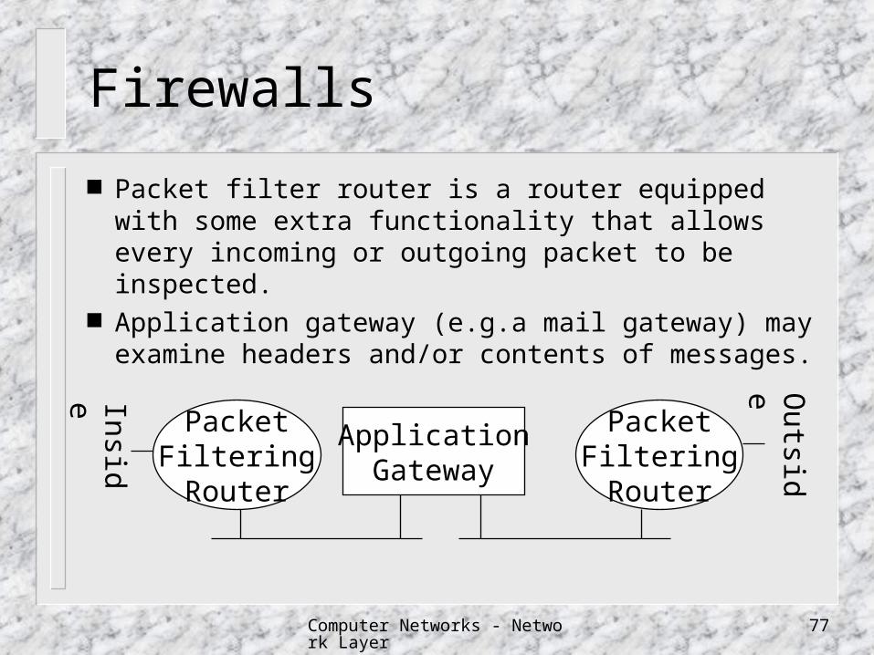
Firewalls
Packet filter router is a router equipped with some extra functionality that allows every incoming or outgoing packet to be inspected.
Application gateway (e.g.a mail gateway) may examine headers and/or contents of messages.
ApplicationGateway
PacketFilteringRouter
PacketFilteringRouter
Inside Outsid
e
Computer Networks - Network Layer 78
Internet Network Layer Protocol
The IP (Internal Protocol) Protocol IP Addressing Subnets Internet Control Protocols
The Internet Control Message Protocol (ICMP) The Address Resolution Protocol (ARP) The Reverse Address Resolution Protocol (RAR
P)
Computer Networks - Network Layer 79
Internet Network Layer Protocol
The Interior Gateway Routing Protocol: Open Shortest Path First (OSPF)
The Exterior Gateway Routing Protocol: Border Gateway Protocol (BGP)
Internet Multicasting Mobile IP Classless InterDomain Routing (CIDR) IPv6
Computer Networks - Network Layer 80
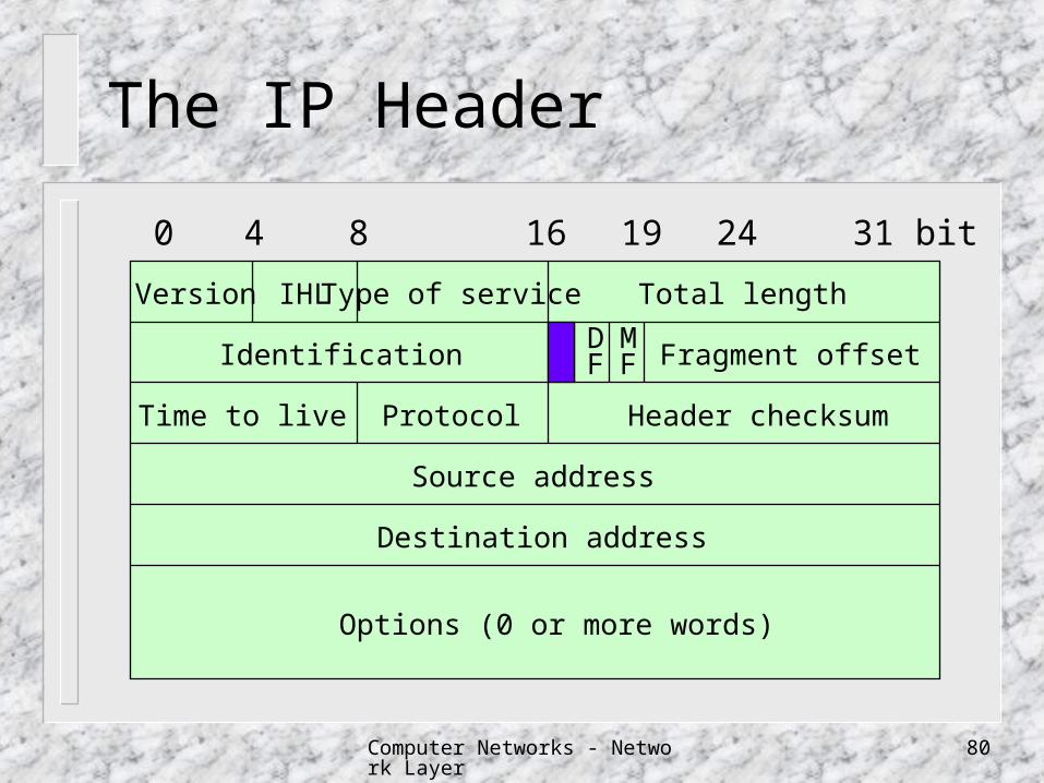
The IP Header
0 4 8 16 19 24 31 bit
Version IHL Type of service Total length
Identification Fragment offsetDF
MF
Time to live Protocol Header checksum
Source address
Destination address
Options (0 or more words)
Computer Networks - Network Layer 81
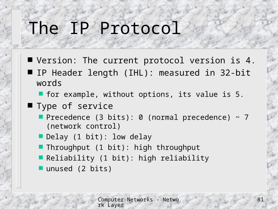
The IP Protocol
Version: The current protocol version is 4. IP Header length (IHL): measured in 32-bit words
for example, without options, its value is 5.
Type of service Precedence (3 bits): 0 (normal precedence) ~ 7 (network
control) Delay (1 bit): low delay Throughput (1 bit): high throughput Reliability (1 bit): high reliability unused (2 bits)
Computer Networks - Network Layer 82
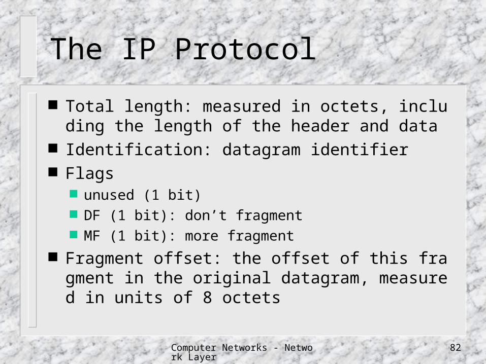
The IP Protocol
Total length: measured in octets, including the length of the header and data
Identification: datagram identifier Flags
unused (1 bit) DF (1 bit): don’t fragment MF (1 bit): more fragment
Fragment offset: the offset of this fragment in the original datagram, measured in units of 8 octets
Computer Networks - Network Layer 83
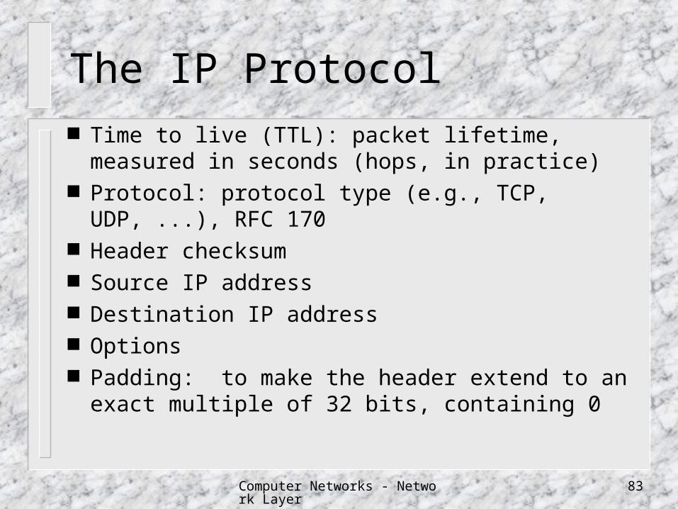
The IP Protocol Time to live (TTL): packet lifetime, measured in
seconds (hops, in practice) Protocol: protocol type (e.g., TCP, UDP, ...), RFC 170 Header checksum Source IP address Destination IP address Options Padding: to make the header extend to an exact
multiple of 32 bits, containing 0

Computer Networks - Network Layer 84
IP Options Security
to specify how secret the datagram is
Strict source routing to give the complete path to be followed
Loose source routing to give a list of routers not to be missed
Record route to make each router append its IP address
Timestamp to make each router append its address and timestamp

Computer Networks - Network Layer 85
IP Option Code
Copy (1 bit): 0: the option will only be copied into the first fragment and n
ot to all fragments 1: the option should be copied into all fragments
Class (2 bits) 0: datagram or network control 1: reserved 2: debugging and measurement 3: reserved
Number (5 bits)

Computer Networks - Network Layer 86
IP Option Number
Class Number Length Description
0
0
0
0
0
0
0
2
1
0
2
3
7
8
9
4
1
1
11
var
var
4
var
var
end of option list
no operation
security and handling restriction
loose source routing
record route
stream identifier
strict source routing
internet timestamp
Computer Networks - Network Layer 87
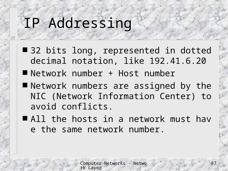
IP Addressing
32 bits long, represented in dotted decimal notation, like 192.41.6.20
Network number + Host number Network numbers are assigned by the NIC
(Network Information Center) to avoid conflicts.
All the hosts in a network must have the same network number.

Computer Networks - Network Layer 88
IP Addresses
1 2 3 Range of hostClass 01234567890123456789012345678901 addresses
A 0Network Host1.0.0.0 to127.255.255.255
E 11110 Reserved for future use240.0.0.0 to247.255.255.255
D 1110 Multicast address224.0.0.0 to239.255.255.255
C 110 Network Host192.0.0.0 to223.255.255.255
B 10 Network Host128.0.0.0 to191.255.255.255
Computer Networks - Network Layer 89
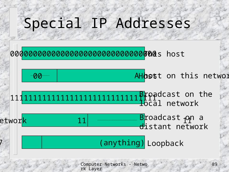
Special IP Addresses
00000000000000000000000000000000
11111111111111111111111111111111
127 (anything)
00 00 Host
Network 11 11
This host
A host on this network
Broadcast on thelocal network
Broadcast on adistant network
Loopback
Computer Networks - Network Layer 90
Network Growth Problem
Problem Immense administrative overhead
Every time a new network is installed the system administrator has to contact NIC to get a new network number.
Then this number must be announced worldwide.
Large routing table Solution: To minimize network numbers by
sharing one network number among multiple physical networks
Computer Networks - Network Layer 91
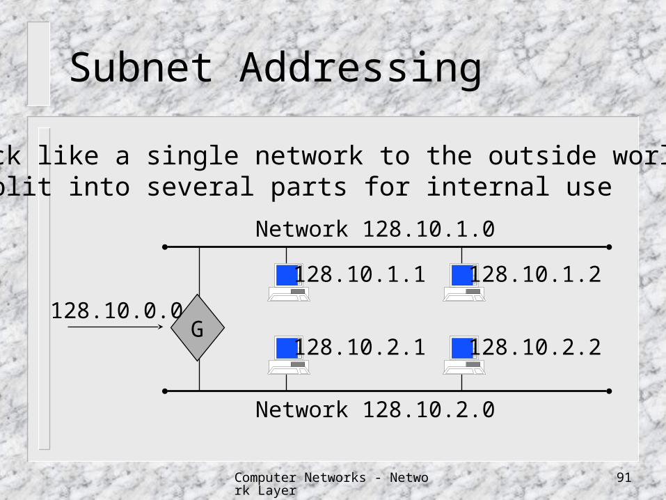
Subnet Addressing
G128.10.2.1
128.10.1.2
128.10.2.2
128.10.1.1
128.10.0.0
Network 128.10.2.0
Network 128.10.1.0
•ack like a single network to the outside world•split into several parts for internal use

Computer Networks - Network Layer 92
Subnets
Network Subnet HostIP address
Subnet mask 11 11 11 11 00 00
The standard does not restrict subnet masks to select contiguous bits of the address.
Host PartA Class B Network
Computer Networks - Network Layer 93
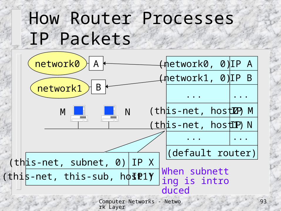
How Router Processes IP Packets
(network0, 0)
(network1, 0)
IP A
IP B
... ...
(this-net, host0) IP M
(this-net, host1) IP N... ...
(default router)
A
B
network0
network1
M N
(this-net, subnet, 0) IP X
(this-net, this-sub, host1) IP Y When subnetting is introduced
Computer Networks - Network Layer 94
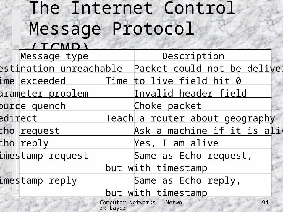
The Internet Control Message Protocol (ICMP)
Message type DescriptionDestination unreachable Packet could not be deliveredTime exceeded Time to live field hit 0Parameter problem Invalid header fieldSource quench Choke packetRedirect Teach a router about geographyEcho request Ask a machine if it is aliveEcho reply Yes, I am aliveTimestamp request Same as Echo request,
but with timestampTimestamp reply Same as Echo reply,
but with timestamp
Computer Networks - Network Layer 95
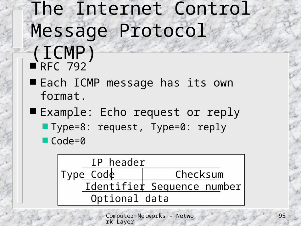
The Internet Control Message Protocol (ICMP) RFC 792 Each ICMP message has its own format. Example: Echo request or reply
Type=8: request, Type=0: reply Code=0
IP headerType Code Checksum Identifier Sequence number
Optional data
Computer Networks - Network Layer 96
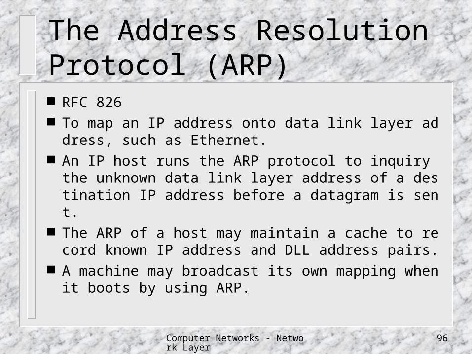
The Address Resolution Protocol (ARP) RFC 826 To map an IP address onto data link layer address, such
as Ethernet. An IP host runs the ARP protocol to inquiry the unknow
n data link layer address of a destination IP address before a datagram is sent.
The ARP of a host may maintain a cache to record known IP address and DLL address pairs.
A machine may broadcast its own mapping when it boots by using ARP.
Computer Networks - Network Layer 97
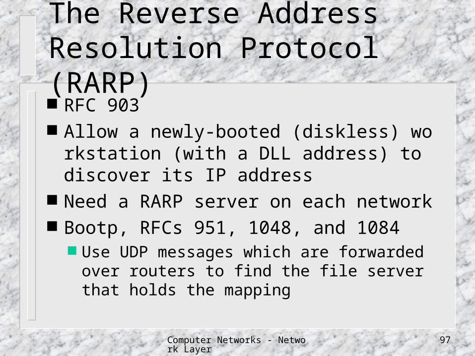
The Reverse Address Resolution Protocol (RARP) RFC 903 Allow a newly-booted (diskless) workstation
(with a DLL address) to discover its IP address Need a RARP server on each network Bootp, RFCs 951, 1048, and 1084
Use UDP messages which are forwarded over routers to find the file server that holds the mapping
Computer Networks - Network Layer 98
The Interior Gateway Routing Protocol A Routing Protocol within an autonomous syst
em (AS). Internet interior gateway protocol
Original: a distance vector protocol, Routing Information Protocol (RIP), based on the Bellman-Ford algorithm
Successor (1979): a link state protocol Now (1990): Open Shortest Path First (OSPF), RF
C 1247 (ver. 1) and RFC 1583 (ver. 2).
Computer Networks - Network Layer 99
Objectives of OSPF
published in the open literature to support a variety of distance metrics: distance,
delay, ... a dynamic algorithm to support routing based on type of service load balancing support for hierarchical systems security tunneling
Computer Networks - Network Layer 100
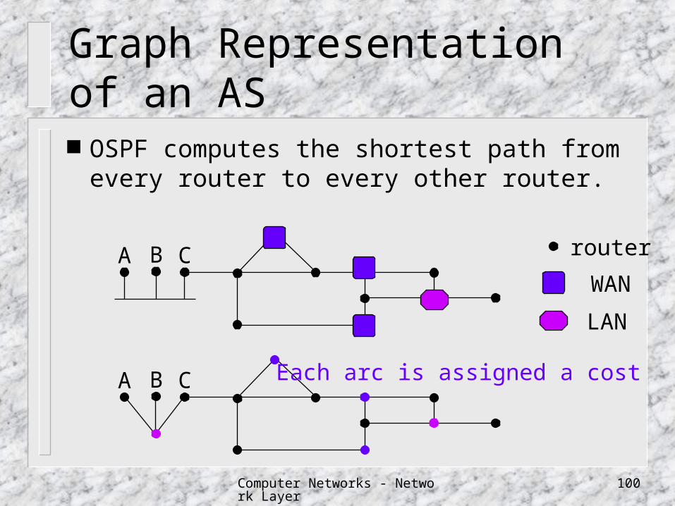
Graph Representation of an AS
OSPF computes the shortest path from every router to every other router.
router
WAN
LAN
A B C
A B C Each arc is assigned a cost
Computer Networks - Network Layer 101
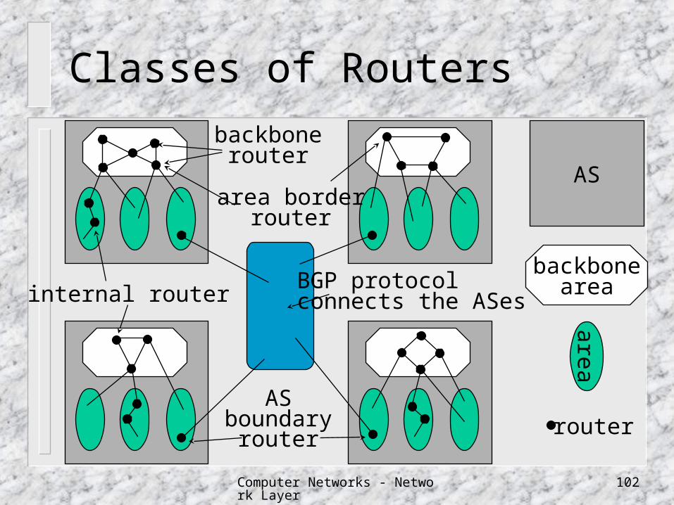
Areas and Backbone Areas
An AS can be divided into numbered areas an area is a network or a set of continuous networks (a
generalization of a subnet) areas do not overlap Within an area, each router has the same link state data
bases and runs the same shortest path algorithm
backbone area (area 0) all areas within an AS are connected to the backbone, p
ossibly by tunnels
Computer Networks - Network Layer 102
Classes of Routers
internal router
backbonerouter
backbonearea
area
area borderrouter
ASboundary
router
AS
BGP protocolconnects the ASes
router

Computer Networks - Network Layer 103
Open Shortest Path First (OSPF)
Type of service routing: multiple graphs one labeled with the costs when delay is the metric one labeled with the costs when throughput is the
metric one labeled with the costs when reliability is the m
etric Three kinds of routes: intra-area, inter-area an
d inter-AS.
Computer Networks - Network Layer 104
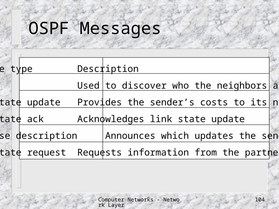
OSPF Messages
Message type Description
Hello Used to discover who the neighbors are
Link state update Provides the sender’s costs to its neighbors
Link state ack Acknowledges link state update
Database description Announces which updates the sender has
Link state request Requests information from the partner

Computer Networks - Network Layer 105
OSPF Messages
When a router boots, it sends HELLO messages on all of its point-to-point lines and multicasts then on LANs to the group consisting of all the other routers.
During normal operation, each router periodically floods LINK STATE UPDATE messages to each of its adjacent routers. Routers also send these messages when a line goes up or down or its cost changes.
Computer Networks - Network Layer 106
OSPF Messages
DATABASE DESCRIPTION messages give the sequence numbers of all the link state entries currently held by the sender. By comparing its own values with those of the sender, the receiver can determine who has the most recent values. These messages are used when a line a brought up.
Computer Networks - Network Layer 107
The Exterior Gateway Routing Protocol A Routing Protocol between ASes
The main goal of an interior gateway protocol is to route efficiently, while the exterior gateway protocols have to worry about “politics”.
Border Gateway Protocol (BGP) described in RFC 1654 BGP1 in 1989, current version BGP4 in 1993. fundamentally a distance vector protocol.
Computer Networks - Network Layer 108
Policies
Political, security, or economic considerations No transit traffic through certain ASes. Never put Iraq on a router starting at the Pentago
n. Only transit Albania if there is no alternative to th
e destination. Traffic starting or ending at IBM should not trans
it Microsoft.
Computer Networks - Network Layer 109
Border Gateway Protocol (BGP)
AB C
D
E
FG
H
I J
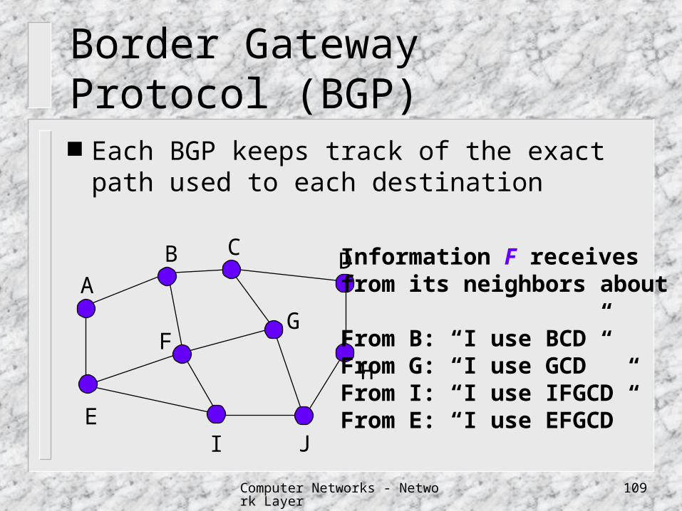
Information F receivesfrom its neighbors about D
From B: “I use BCD”From G: “I use GCD”From I: “I use IFGCD”From E: “I use EFGCD”
Each BGP keeps track of the exact path used to each destination
Computer Networks - Network Layer 110
Border Gateway Protocol (BGP)
After all the paths come in from the neighbors, the best can be determined.
Since each router keeps the exact routes used, the count-to-infinite problem can be easily solved.
BGPs uses TCP as its transport protocol (port 179) for reliable transmission.
Computer Networks - Network Layer 111
How BGP Solves The Count-to-Infinity Problem
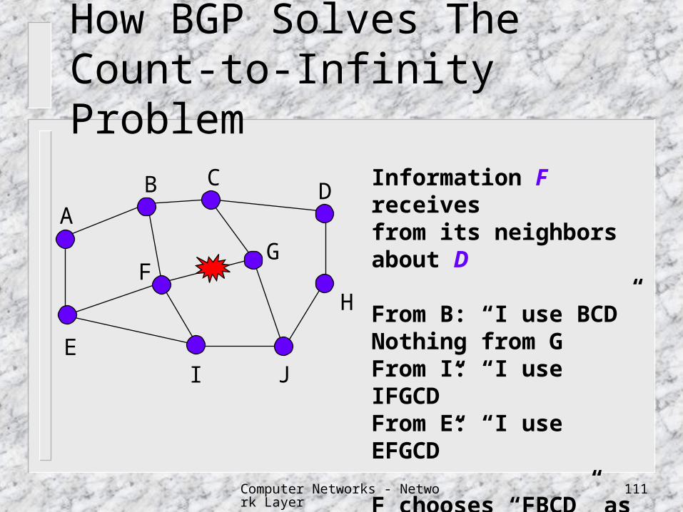
Information F receivesfrom its neighbors about D
From B: “I use BCD”Nothing from GFrom I: “I use IFGCD”From E: “I use EFGCD”
F chooses “FBCD” as its new route
AB C
D
E
FG
H
I J
Computer Networks - Network Layer 112
Internet Multicasting
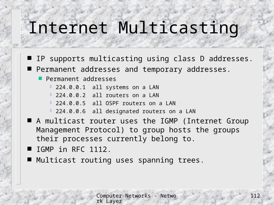
IP supports multicasting using class D addresses. Permanent addresses and temporary addresses.
Permanent addresses 224.0.0.1 all systems on a LAN 224.0.0.2 all routers on a LAN 224.0.0.5 all OSPF routers on a LAN 224.0.0.6 all designated routers on a LAN
A multicast router uses the IGMP (Internet Group Management Protocol) to group hosts the groups their processes currently belong to.
IGMP in RFC 1112. Multicast routing uses spanning trees.
Computer Networks - Network Layer 113
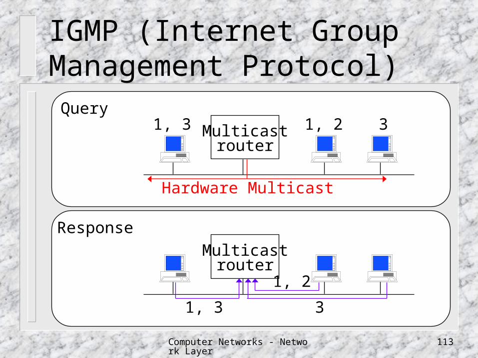
IGMP (Internet Group Management Protocol)
Multicastrouter
Query
Multicastrouter
Response
1, 2 31, 3
1, 3 3
1, 2
Hardware Multicast
Computer Networks - Network Layer 114
Mobile IP
Problems with host mobility in Internet IP address implies host location
Major goals of Mobile IP Mobile host can use its home IP address anywhere. Software changes to the fixed hosts were not permitted changes to the router software and tables were not
permitted most packets for mobile hosts should not make detours on
the way no overhead should be incurred when at home
Computer Networks - Network Layer 115
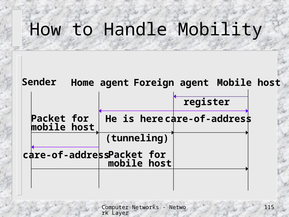
How to Handle Mobility
Home agent Foreign agent Mobile host
register
care-of-addressHe is herePacket formobile host
(tunneling)
care-of-address Packet formobile host
Sender
Computer Networks - Network Layer 116
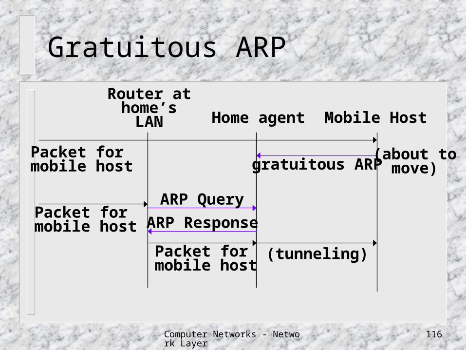
Gratuitous ARP
Home agent Mobile Host
ARP Response
Router athome’sLAN
Packet formobile host
ARP Query
Packet formobile host
Packet formobile host gratuitous ARP
(about tomove)
(tunneling)
Computer Networks - Network Layer 117
IP Addressing Problems
32-bit IP address space is not enough Organizing the address space by classes wast
es millions of them a class B address is far too large for most organiz
ations the routing table explosion
every router in the Internet would need a table with half a million entries, if that much class C networks are in use
Computer Networks - Network Layer 118
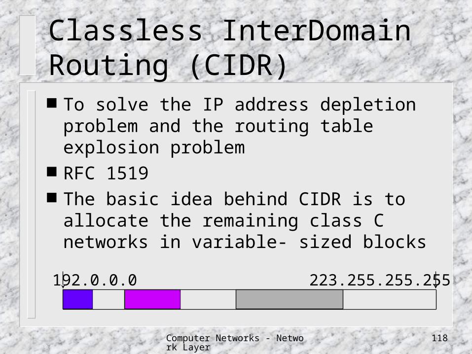
Classless InterDomain Routing (CIDR) To solve the IP address depletion problem
and the routing table explosion problem RFC 1519 The basic idea behind CIDR is to allocate
the remaining class C networks in variable- sized blocks
192.0.0.0 223.255.255.255
Computer Networks - Network Layer 119
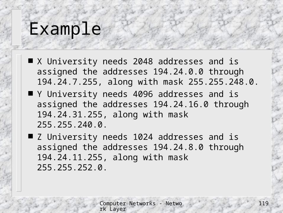
Example
X University needs 2048 addresses and is assigned the addresses 194.24.0.0 through 194.24.7.255, along with mask 255.255.248.0.
Y University needs 4096 addresses and is assigned the addresses 194.24.16.0 through 194.24.31.255, along with mask 255.255.240.0.
Z University needs 1024 addresses and is assigned the addresses 194.24.8.0 through 194.24.11.255, along with mask 255.255.252.0.
Computer Networks - Network Layer 120
Example
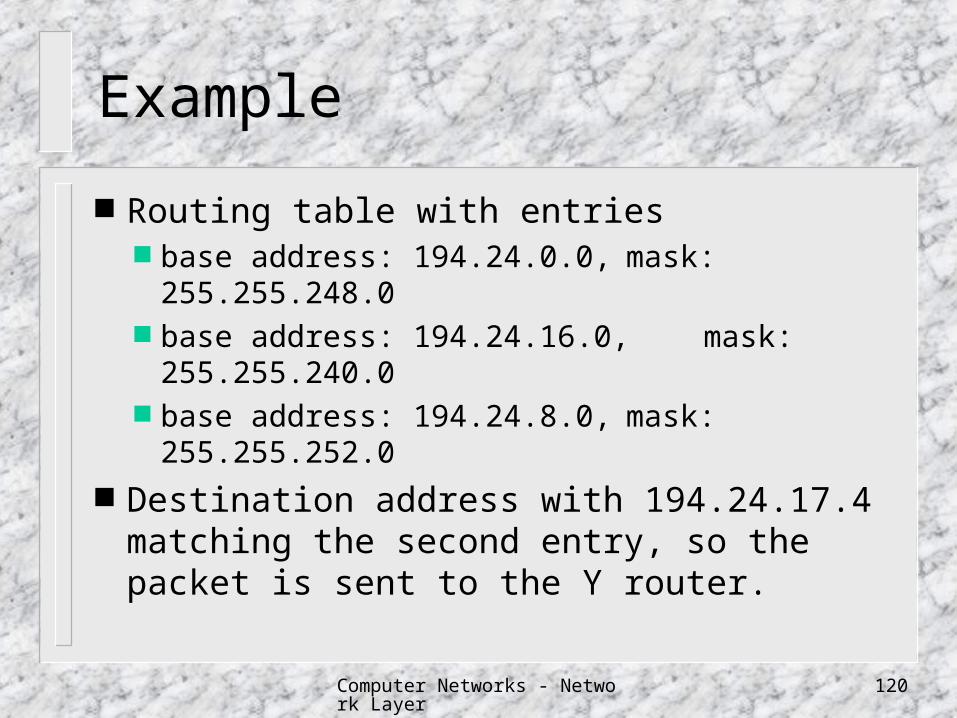
Routing table with entries base address: 194.24.0.0, mask: 255.255.248.0 base address: 194.24.16.0, mask:
255.255.240.0 base address: 194.24.8.0, mask: 255.255.252.0
Destination address with 194.24.17.4 matching the second entry, so the packet is sent to the Y router.

Computer Networks - Network Layer 121
Classless InterDomain Routing (CIDR) The world was partitioned into zones, each given a portion
of the class C address space: Addresses 194.0.0.0 to 195.255.255.255 for Europe Addresses 196.0.0.0 to 197.255.255.255 for Others Addresses 198.0.0.0 to 199.255.255.255 for North America Addresses 200.0.0.0 to 201.255.255.255 for Central and South
America Addresses 202.0.0.0 to 203.255.255.255 for Asia and Pacific Addresses 204.0.0.0 to 207.255.255.255 for Others Addresses 208.0.0.0 to 223.255.255.255 reserved for future use

Computer Networks - Network Layer 122
IP Address Allocation
Class A address allocation is restricted. Class B address are also restricted .They will be allocated onl
y if the need for them is justified. Class C addresses are allocated with a contiguous block of ad
dresses which consists of several contiguous class C addresses.Class C addresses are being distributed to ISPs so that the allocation could last at least two years.
If a subscriber has a requirement for more than 4096 IP address, a Class B network number may be allocated.
Organizations are encouraged to use Variable Length Subnet Mask for efficient use of address space.
Computer Networks - Network Layer 123
IPv6
A modified combined version of Deering and Francis proposals. SIPP (Simple Internet Protocol Plus)
Longer addresses Simplification of headers Support for options Security and authentication Type of services
Computer Networks - Network Layer 124
The IPv6 Header
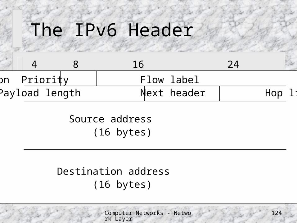
Version Priority Flow labelPayload length Next header Hop limit
Source address (16 bytes)
Destination address (16 bytes)
0 4 8 16 24 31
Computer Networks - Network Layer 125
The IPv6 Protocol
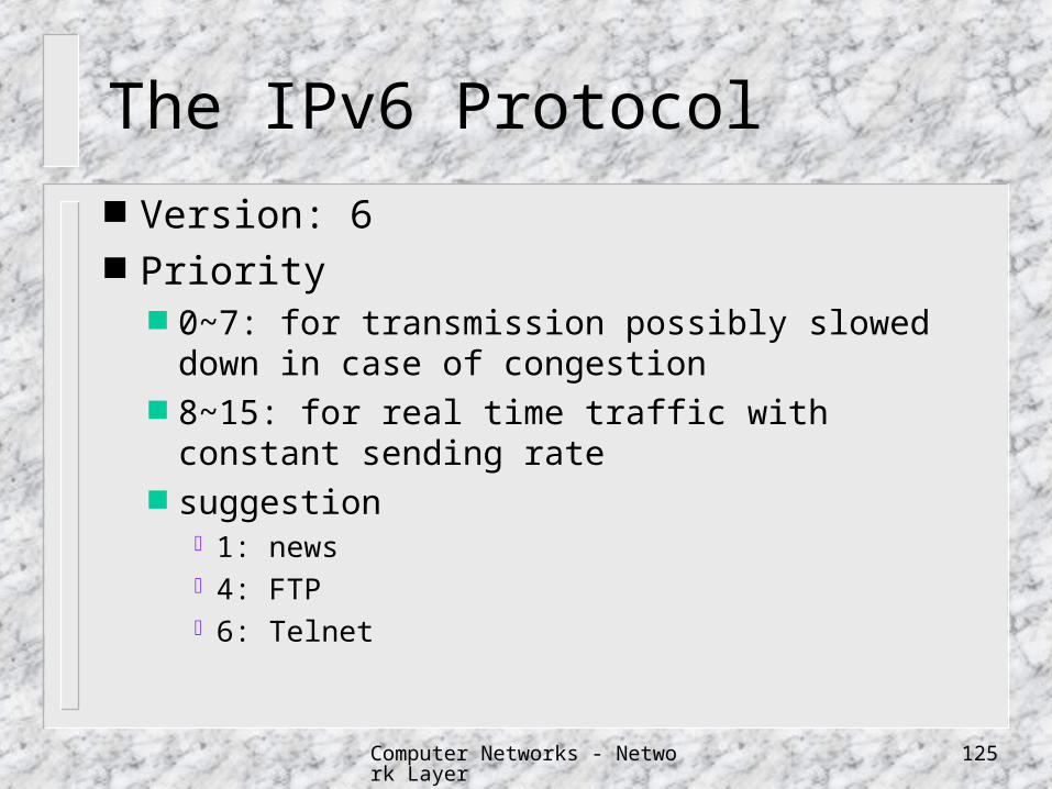
Version: 6 Priority
0~7: for transmission possibly slowed down in case of congestion
8~15: for real time traffic with constant sending rate suggestion
1: news 4: FTP 6: Telnet
Computer Networks - Network Layer 126
The IPv6 Protocol
Flow label: for setting up a pseudo connection with particular properties and requirements
Payload length: information bytes following the 40 byte header
Next header: specify which of the (currently) six extension headers, if any, follows the header. If the header is the last IP header, the Next header specifies the transport protocol handler.
Hop limit: for limiting packet lifetime Source address and Destination address
Computer Networks - Network Layer 127
IPv6 Address Expression
Written as eight groups of four hexadecimal digits with colons between groups8000:0000:0000:0000:0123:4567:89AB:CDEF
optimizations8000::123:4567:89AB:CDEF
IPv4 addresses::192.31.20.46