computer networks - birla institute of technology and ... · computer networks lecture-2 january...
TRANSCRIPT

BITS Pilani Pilani | Dubai | Goa | Hyderabad
Computer Networks Lecture-2 January 10, 2012
Rahul Banerjee, PhD (CSE)
Professor, Department of Computer Science & Information Systems
E-mail: [email protected]

BITS Pilani, Deemed to be University under Section 3 of UGC Act, 1956
A Recap of the types of applications and services benefitting from networking
Interconnecting Networks for forming Internetworks Architecture of the Internet What is the Internet today? The Internet and the World-Wide Web Who decides about the Internet? Of The Internet, Intranet and Extranet Protocols, Layers, Interfaces, Logical / Virtual Communication &
Services Of Network Architectures & Network Reference Models Select References to the literature Summary
Interaction Points

Examples of Types of Applica1ons benefi5ng from Networking
• Types of applications & services: – hard real-time applications & services, – soft real-time applications & services, – non-real-time / best-effort / delay-tolerant applications /
services
• Examples of each kind of applications and services • About the significance of application-driven and
economics-constrained nature of network system design approaches
• Case-study of the Networking aspects of the Microsoft Easy Living Research Experiment
10/01/12 (c) Dr. Rahul Banerjee, BITS Pilani, INDIA 3
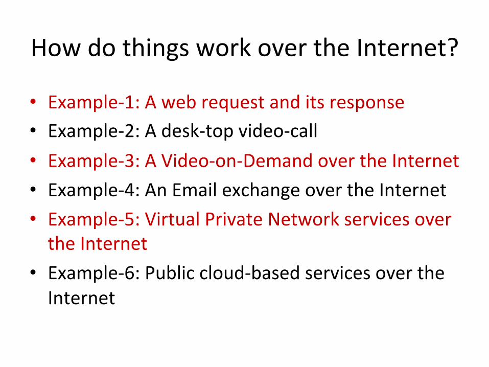
How do things work over the Internet?
• Example-‐1: A web request and its response • Example-‐2: A desk-‐top video-‐call • Example-‐3: A Video-‐on-‐Demand over the Internet • Example-‐4: An Email exchange over the Internet • Example-‐5: Virtual Private Network services over the Internet
• Example-‐6: Public cloud-‐based services over the Internet

10/01/12 (c) Dr. Rahul Banerjee, BITS Pilani, INDIA 5
An Example of a Computer Network

Another Form of Ethernet LAN
6 (c) Dr. Rahul Banerjee, BITS, Pilani, India
The Shared Ethernet hub
Personal Computer
Network Printer
Worksta1on
Worksta1on
Laptop Computer
Worksta1on
Tablet PC

(c) Dr. Rahul Banerjee, BITS Pilani, INDIA 7
Local Area Internetwork / Intranet • Traditionally, a Campus Internetwork is a campus-wide
internetwork of individual LANs which may be geographically spread over the part or whole of a single campus. This sometimes called campus intranet.
• In common practice, the entire campus internetwork including its communication subnet is wholly owned by a single organization or institution.
• Usually, the campus internetworks use LAN technology; however, it is possible to use WAN technology, when so desirable.
• The latter may be desirable in some cases when the campus is very large and comprises of a vast set of buildings spread over it. Protocols used in both of these cases at the lower layers, are, generally, different. 10/01/12

(c) Dr. Rahul Banerjee, BITS, Pilani, India 8
Some Terms Related to Networks
• Channel <application-level logical / virtual communication path>
• Services: Functionalities provided by a layer / protocol / entity
• Interfaces: Peer-to-Peer / Layer-to-Layer / entity-to-entity
• Service Access Points: defined addresses / ports through which data / parameters are passed
• Tunneling <Encapsulation & Decapsulation>
10/01/12 (c) Dr. Rahul Banerjee, BITS Pilani, INDIA 8
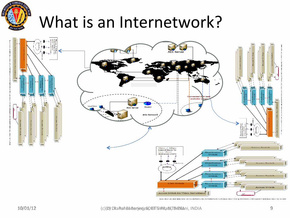
What is an Internetwork?
10/01/12 (c) Dr. Rahul Banerjee, SDET Unit, BITS-‐Pilani, INDIA 9 10/01/12 (c) Dr. Rahul Banerjee, BITS Pilani, INDIA 9

(c) Dr. Rahul Banerjee, BITS Pilani, INDIA 10
Of the Internet, Intranet and Extranet
• The Global Public Internetwork: The Internet • The Wholly Owned / Private Internetwork:
Intranet • The Hybrid Internetwork-- private networks /
internetworks connected through the Internet: Extranet In the early stages of development, technologies used for the internetworks of all type were essentially the same, except probably at the lowest level. This situation is rapidly changing.
10/01/12

10/01/12 (c) Dr. Rahul Banerjee, BITS Pilani, INDIA 11
Architecture of the Internet • Originally, it was a point-to-
point WAN. • Original architecture that led
to ARPANET has evolved over the years that have passed by.
• It is loosely hierarchical. • Currently, Internet
architecture is largely governed by the IAB of the ISoc.
• Has many sub-organs which facilitate evolution and coordinated maintenance of the Internet.
• IESG steers the ISoc in a general way the engineering issues are resolved.
• IETF workgroups do the ground work and by a democratic process helps community in building up engineering solutions through IETF drafts and standards (RFCs) etc.

10/01/12 (c) Dr. Rahul Banerjee, BITS Pilani, INDIA 12
What is the Internet today? • Wide Area Network of variety of networks • Global • Public • Not transparent, as yet • Hybrid topology but largely hierarchical • No single controller • Internet Society (ISoc) oversees, assists --- does
not control • QoS, Security continue to have issues – partly at
least • Web, mail, commerce, education, entertainment,
sharing continue to dominate its application space

References • Larry L. Peterson & Bruce S. Davie: Computer Networks: A Systems Approach,
Fifth Edition, Morgan Kaufmann / Elsevier, New Delhi, 2011. <System design approach>
• S. Keshav: Computer Networking: An Engineering Approach, Pearson Education, New Delhi, 1997.
• A. S. Tanenbaum: Computer Networks, Fifth Edition, Pearson Education, New Delhi, 2012. <Conceptual Approach>
• Y. Zheng and S. Akhtar: Networks for Computer Scientists and Engineers, Oxford University Press, New York, 2002. <Structural approach>
• A. Leon Garcia and I. Widjaja: Communication Networks: Fundamental Concepts and Key Architectures, Second Edition, Tata McGraw-Hill, New Delhi, 2004.
• Mohammed G. Gouda: Elements of Network Protocol Design, Wiley Student Edition, John Wiley & Sons (Pte.) Ltd., Singapore, 2004.
• Thomas G. Robertazzi: Computer Networks and Systems: Queuing Theory and Performance Evaluation, Third Edition, Springer-Verlag, New York, 2000. <Analytical approach>
© Dr. Rahul Banerjee, BITS, Pilani (India) 10/01/12 (c) Dr. Rahul Banerjee, BITS Pilani, INDIA 13

10/01/12 (c) Dr. Rahul Banerjee, BITS Pilani, INDIA 14
Interac1on Points • Examples of Types of Applications benefitting from Networking
– hard real-time, soft real-time, non-real-time / best-effort / delay-tolerant applications / services <with examples>
– case-study movie – Constituent networking components of a smart room setup
• The Internet & its Evolution • About Internet Architecture • Who decides about the Internet? • The Internet versus the World-Wide Web • Protocols, Layers, Interfaces, Virtual Communication and
Services • Select References to the literature • Questions and Answers / Summary

(c) Dr. Rahul Banerjee, BITS Pilani, INDIA 15
Conven1onal Classifica1on of Computer Networks
• Class One: Function-based classification
• Data Networks • Voice Networks • Multimedia Networks ……
• Class Two: Location-and-Distance-based classification
• Personal Area Networks (PANs)
• Local Area Networks (LANs)
• Metropolitan Area Networks (MANs)
• Wide Area Networks (WANs) ….
• Class Three: Forwarding-‐based classifica1on
• Switched Networks • Circuit-‐Switched Networks • Packet-‐Switched Networks
• Shared Networks • Hybrid Networks
• Class Four: Ownership-‐based classifica1on
• Public Networks • Private Networks • Virtual Private Networks
10/01/12

(c) Dr. Rahul Banerjee, BITS Pilani, INDIA 16
Comparing Computer Networks with Distributed Systems
• Terms Computer Network and Distributed System must NOT be used interchangeably since: – In the former, locations and elements of network
remain visible to the user; – In the latter, the underlying network remains
transparent to the user who sees the system as a large uni-processor system.
• Similar differences can be cited in case of Network Operating
Systems and Distributed Operating Systems.
10/01/12

Robert Metcafe’s Ethernet • The original Ethernet protocol proposed and
implemented by Robert Metcafe was actually based on 1-p CSMA/CD protocol
• It did have a scheme that allowed greedy access to the channel by a station which led to lower efficiency
• Schemes like Random Back-off / Exponential Back-off were devised to improve the efficiency to a certain extent
10/01/12 (c) Dr. Rahul Banerjee, SDET Unit, BITS-Pilani, INDIA 17

An Ethernet LAN
18 (c) Dr. Rahul Banerjee, BITS, Pilani, India
Personal Computer
Worksta1on
Worksta1on Workstation

Frames: Factors that maaer!
• Synchronization: Transmitter & Receiver need to be in sync
• Start Delimiter: Required to mark starting bit • End Delimiter: Required to mark the end bit • Control Information: Information suggesting data
handling and interpretation • Error Detection / Correction / Retransmission • Flow Control: Required for avoiding data loss
due to overflow at receiving end • Data Length: Needed if data-field is not of fixed
size 19 (c) Dr. Rahul Banerjee,
BITS, Pilani, India

A Sample Frame Format
n-‐Byte Preamble Start-‐of -‐Frame Delimiter Des1na1on Add. Source Address Length of Data
Data Field Pad Field
Checksum
20 (c) Dr. Rahul Banerjee, BITS, Pilani, India
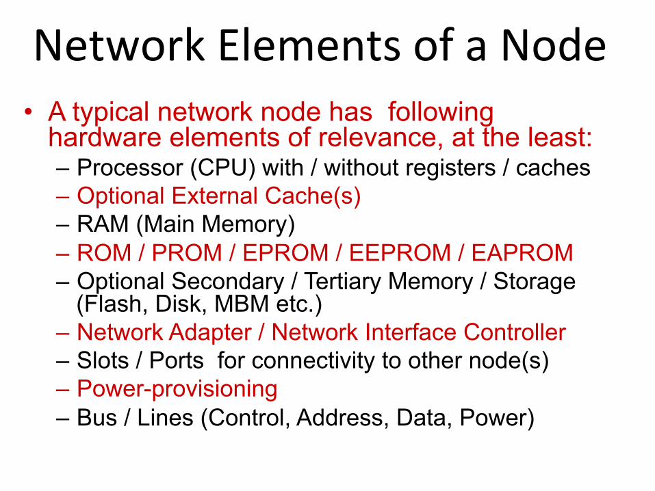
Network Elements of a Node • A typical network node has following
hardware elements of relevance, at the least: – Processor (CPU) with / without registers / caches – Optional External Cache(s) – RAM (Main Memory) – ROM / PROM / EPROM / EEPROM / EAPROM – Optional Secondary / Tertiary Memory / Storage
(Flash, Disk, MBM etc.) – Network Adapter / Network Interface Controller – Slots / Ports for connectivity to other node(s) – Power-provisioning – Bus / Lines (Control, Address, Data, Power)

Elements of a Network Interface Controller / Network Adapter
• A Network Adapter / Interface Controller Unit / Chip / Dongle often comprises of the following elements: – Host bus / line / link – Control Status Registers (often called CSR or simply even as Control
Registers) • logically readable / writable by the CPU
– --à often, a copy of the contents of the CSR is located in some pre-specified location in memory making it simple for CPU to perform R/W operations, as per need
» --à Actual writing to the NIC’s CSR is done by the Device Driver though – Bus Interface Unit – Internal storage (buffer included) – Transceivers for transmission and reception at the physical level
• Data Transfer Methods: DMA (no worry for the CPU) or Programmed I/O (PIO) based Data Transfer (CPU needs to work herein) from the memory of the host node to the NIC / Adapter
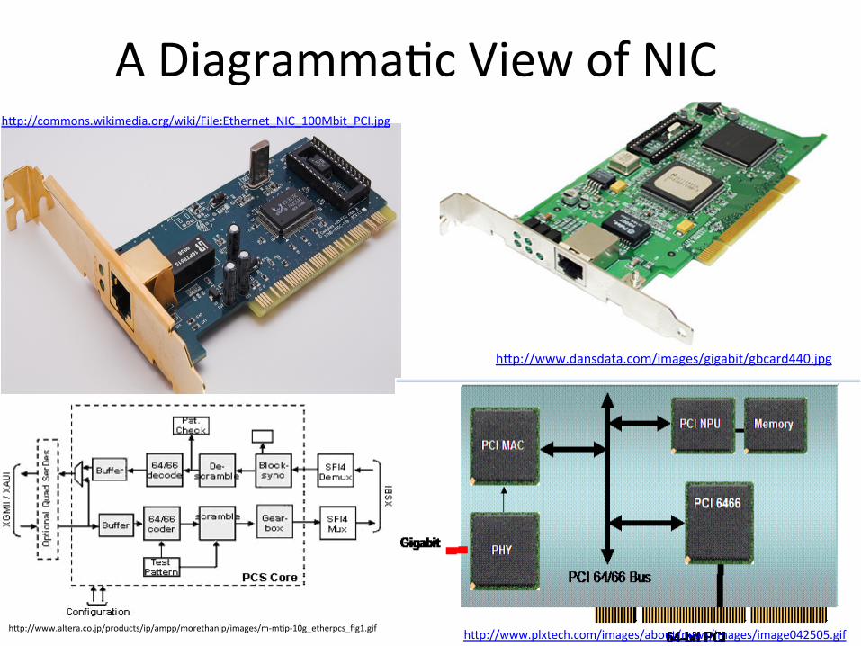
A Diagramma1c View of NIC
hap://www.plxtech.com/images/about/news/images/image042505.gif
hap://commons.wikimedia.org/wiki/File:Ethernet_NIC_100Mbit_PCI.jpg
hap://www.dansdata.com/images/gigabit/gbcard440.jpg
hap://www.altera.co.jp/products/ip/ampp/morethanip/images/m-‐m1p-‐10g_etherpcs_fig1.gif

Examples of Ethernet Adapters
Source: hap://www.altera.co.jp/products/ip/ampp/morethanip/images/m-‐m1p-‐10g_etherpcs_fig1.gif (c)

25 (c) Dr. Rahul Banerjee, BITS, Pilani, India
Based on IEEE documents with instructional modifications Copyright: IEEE Inc., N.Y.
The IEEE 802.x Architecture and Specifications revisited

Operation of a Bridge with Two LANs
26 (c) Dr. Rahul Banerjee, BITS, Pilani, India
Source Destination
S
H
H H H
H H
H
Hub

Some Common Layer-‐2 Switches Cisco L2 Managed Switches
© Cisco, Inc.

Fixed Lasers
Electronic Switches
GxG MEMS
Group 1
LxM Crossbar
Linecard 1
Linecard 2
Linecard L
Group 2
LxM Crossbar
Linecard 1
Linecard 2
Linecard L
LxM Crossbar
Linecard 1
Linecard 2
Linecard L
Group G
MxL Crossbar
Linecard 1
Linecard 2
Linecard L
Electronic Switches
Optical Receivers
Group 1
MxL Crossbar
Linecard 1
Linecard 2
Linecard L
Group 2
MxL Crossbar
Linecard 1
Linecard 2
Linecard L
Group G
GxG MEMS
GxG MEMS
GxG MEMS
1
2
3
M
Static MEMS
1
2
3
M
1
2
3
M
1
2
3
M
1
2
3
M
1
2
3
M
1
2
3
M
An Example of a Hybrid Switching Fabric
© Dr. Nick McKeown, Stanford University <modified version>

An Example of Network (LAN) Switches
Cisco Catalyst 3750 Series Switches
© Cisco, Inc.

Cisco Catalyst 4500 Series of Switches Cisco Catalyst 4500 Series Switches
(Used in several places in the Institute as Distribution Switches)
© Cisco, Inc.

Cisco Catalyst 6500 Series of Switches Cisco Catalyst 6500 Series
Switches
(One of these is OUR Core Switch located in the IPC
System Room)
© Cisco, Inc.

32
A Bus Topology based Computer Network
SHARED BUS
(c) Dr. Rahul Banerjee, BITS-Pilani, INDIA
N1 N2 N3 N4

33
A Ring Topology based Computer Network
C
C
C
C
C
(c) Dr. Rahul Banerjee, BITS-Pilani, INDIA

34
A Ring Topology based Computer Network
C
C
C
C
C
(c) Dr. Rahul Banerjee, BITS-Pilani, INDIA

35
A Tree Topology based Computer Network
NC1 NC2
NC11
NR
NC21
NC22
NC12
(c) Dr. Rahul Banerjee, BITS-Pilani, INDIA

36
A Star Topology based Computer Network
C
C
C
Switch
(c) Dr. Rahul Banerjee, BITS-Pilani, INDIA
S
N1
N2
N3
N4

(c) Dr. Rahul Banerjee, BITS, Pilani, India 37
Summary of Network Topologies • Bus Topology
– Shared – Switched
• Tree Topology • Ring Topology
– Single – Double
• Star Topology • Irregular Topology • Complete Topology

Network Architecture & Reference Models
• Architecture versus Reference Model: A simplistic perspective: – Architecture: It may be seen as a detailed
generic blueprint with unambiguous definitions of services, interfaces, organization and defined protocols that helps in design and implementation of a set of relevant protocol stack / suite based network / internetwork
– Reference Model: It is the same as the architecture minus the specifically defined readily usable protocols.
Tuesday 10 January 12 38 (c) Dr. Rahul Banerjee, BITS-‐Pilani, INDIA

Network Architectures & Reference Models
• Examples: – TCP/IP Architecture &
TCP/IP Reference Model
– OSI Reference Model & OSI Architecture
– ATM Reference Model & ATM Architecture
– Our own Hypothetical Reference Model (slide-5)
Tuesday 10 January 12 39 (c) Dr. Rahul Banerjee, BITS-‐Pilani, INDIA
LLC Sub-layer
MAC Sub-layer
Physical layer

40
Data Link Layer
Physical Layer
Transport Layer
Network Layer
Applica9on Layer
Presenta9on Layer
Session Layer
The ISO OSI Reference Model
(c) Dr. Rahul Banerjee, BITS-‐Pilani, INDIA

41
The ISO OSI Reference Model
(c) Dr. Rahul Banerjee, BITS-‐Pilani, INDIA

Copyright: Dr. Rahul Banerjee BITS, Pilani (India) 42
Data Link Layer
Physical Layer
Transport Layer
Network Layer
Applica9on Layer
A Hypothetical Network Reference Model for Easy Conceptual Understanding
Layer-‐5
Layer-‐4
Layer-3
Layer-2
Layer-1
Often on the NIC card or chip

43
A Simplified Network Reference Model <for Instruction>
Host-1 Host-2
Application Layer Application Layer
Upper Layer-‐to-‐ Lower Layer Interface Upper Layer-‐to-‐ Lower Layer Interface
Upper Layer-‐to-‐ Lower Layer Interface Upper Layer-‐to-‐ Lower Layer Interface
Upper Layer-‐to-‐ Lower Layer Interface Upper Layer-‐to-‐ Lower Layer Interface
Same Layer -to- Same Layer Virtual Communication Interface
Same Layer -to- Same Layer Virtual Communication Interface
Same Layer -to- Same Layer Virtual Communication Interface
Same Layer -to- Same Layer Virtual Communication Interface
Same Layer -to- Same Layer Physical Communication Interface
(c) Dr. Rahul Banerjee, BITS-‐Pilani, INDIA

Copyright: Dr. Rahul Banerjee BITS, Pilani (India) 44
Application Layer • Application Layer is a layer of the Network Architecture
that is primarily concerned with getting TPDU from the lower layer (usually Transport Layer) and delivering it to the Application and vice-versa (with or without explicit presentation and session management support).
• Examples: HTTP, DHCP, DNS, SNMP, FTP (in the context of the TCP/IP Architecture).
• Web-services, Video-on-Demand over the network, Video/Voice-conferencing over the network etc. are examples of Applications that reside atop the protocols belonging to this layer.
Copyright: Dr. Rahul Banerjee BITS, Pilani (India) 45
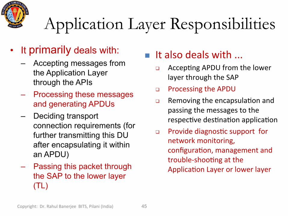
Application Layer Responsibilities
• It primarily deals with: – Accepting messages from
the Application Layer through the APIs
– Processing these messages and generating APDUs
– Deciding transport connection requirements (for further transmitting this DU after encapsulating it within an APDU)
– Passing this packet through the SAP to the lower layer (TL)
n It also deals with ... q Accep1ng APDU from the lower
layer through the SAP q Processing the APDU q Removing the encapsula1on and
passing the messages to the respec1ve des1na1on applica1on
q Provide diagnos1c support for network monitoring, configura1on, management and trouble-‐shoo1ng at the Applica1on Layer or lower layer

(c) Dr. Rahul Banerjee, BITS, Pilani, India 46
Transport Layer: What is it?
• Transport Layer is a layer of the Network Architecture that is primarily concerned with: – getting TPDU from the upper layer (usually
Application Layer) and – delivering it to the same layer at the intended
destination node (through the underlying Network Layer).
• Converse is also true of the targeted set of responsibilities of this layer.

(c) Dr. Rahul Banerjee, BITS, Pilani, India 47
Transport Layer Responsibilities <another perspective>
• It primarily deals with: – Accepting APDU from the
Application Layer through the Service Access Point (SAP)
– Processing these APDU – Deciding transport
connection requirements (for further transmitting this DU after encapsulating it within a TPDU)
– Passing this packet through the SAP to the lower layer (NL)
n It also deals with ... q Accep1ng TPDU from the lower
layer through the SAP q Processing the TPDU q Removing the encapsula1on and
passing the messages to the respec1ve des1na1on applica1on
q Provide diagnos1c support for network monitoring, configura1on, management and trouble-‐shoo1ng at the Applica1on Layer or lower layer

(c) Dr. Rahul Banerjee, BITS, Pilani, India 48
Network Layer • Network Layer is primarily concerned with getting NLDU / Packets from
the source node and delivering it to the intended destination node (through none or many intermediate nodes).
• Additional responsibilities of this layer include: – Providing support for connection-oriented / connectionless services as the
case may be (depending upon the protocol stack and need) – Provide diagnostic support for network monitoring, configuration,
management and trouble-shooting at the Network Layer or higher layer. • Packet handling, packet management, Routing are its major
responsibilities.
n In the context of packet rou1ng, network layer structural design goals include: q Ensuring the shortest possible delay and thereby the highest throughput at the least
possible cost q Ensuring acceptably reliable packet delivery (may be op1onal in some cases) q Ensuring secure packet delivery (may be op1onal in some cases)

(c) Dr. Rahul Banerjee, BITS, Pilani, India 49
Data Link Layer
• Data Link Layer consists of two sub-layers: – Media Access Control (MAC) sub-layer & – Logical Link Control (LLC) sub-layer.
• Major Issues involved in the design of the Data Link Layer include: – Which services are to be provided to each of the adjacent
layers? – Exactly when to provide these services? – How to provide them? – To whom should they be provided?

(c) Dr. Rahul Banerjee, BITS, Pilani, India 50
Physical Layer
• Physical Layer deals with transmission of raw digital data using analog or digital signal.
• This layer is concerned with the logic type (negative or positive), amplitude of the signal, signal representation, bit-length, direction of transmission etc.
• It deals with connection-establishment and termination.
n This layer is, in a nutshell, a layer that deals with various electrical and mechanical characteris1cs of every physical component of a computer network.
n Exact electrical, mechanical and procedural Interface Defini1on is therefore its responsibility.
n Choice and use of the physical medium are the Physical Layer Design Issues.

(c) Dr. Rahul Banerjee, BITS, Pilani, India 51
A Few More Networking Terms • Repeaters / Repeater Hubs / Shared Hubs: where usually Physical
layer / level exist with L1-protocol data unit (raw bits) regeneration and onward transmission
• Managed Hubs / Layer-2 Switching Hubs: where Physical and Data Link layers / levels exist with ability to handle and deliver Layer-2-protocol data unit (frame)
• Bridges: where Physical and Data Link layers / levels exist with L2-protocol data unit (frame) processing and forwarding
• Switches: where Physical and Data Link and / or Network (sometimes even higher) layers / levels exist with Layer-2 and / or Layer-3-protocol data unit (frame / packet) processing, switched routing / forwarding
• Routers: where Physical and Data Link and Network layers / levels exist with L3-protocol data unit (packet) processing, routing and forwarding
• Gateways: where two or more different networks meet and may require protocol / message translation capabilities
• Clouds: abstraction of node connectivity in the networking context <details hidden>

Summary • Intranet: Completely private network of networks
• Wireline • Wireless
– Fixed – Mobile
• Hybrid • The Internet: Global public network of networks
• Wireline • Wireless
– Fixed – Mobile
• Hybrid • Extranet: Intranets interconnected via the Internet
Tuesday 10 January 12 52 (c) Dr. Rahul Banerjee, BITS-‐Pilani, INDIA 10/01/12 (c) Dr. Rahul Banerjee, BITS Pilani, INDIA 52

BITS Pilani Pilani | Dubai | Goa | Hyderabad
Thank you!
Rahul Banerjee

BITS Pilani, Deemed to be University under Section 3 of UGC Act, 1956
Project BITS-Connect 2.0

BITS Pilani, Deemed to be University under Section 3 of UGC Act, 1956

BITS Pilani, Deemed to be University under Section 3 of UGC Act, 1956