computer modelling of multiple tee-beam bridges
TRANSCRIPT

Computer Modelling of
Multiple Tee-beam
Bridges
G. Pircher

ii

iii
Master Honours
2006
University of Western Sydney

iv

v
Synopsis
Bridges consisting of multiple parallel pre-stressed and pre-fabricated Tee-beams topped by a
cast-on-site concrete slab are often a cost-effective way of constructing simply-supported and
multi-span bridge structures in many countries world-wide. For the design of these bridges
computer models are often utilised.
This thesis presents a comprehensive discussion of modelling issues encountered in the
practical design work on this bridge type. A chapter on the modelling of various loading
conditions is followed by a detailed discussion of the modelling of the longitudinal load-
bearing system, the Tee-beams, and the lateral load-bearing system, the roadway slab. A
summary of commonly used bridge systems in various countries is also included. All this
material is presented considering design code requirements in various internationally used
specifications.
The information included in this thesis has been used to define specifications for the
implementation of a software tool to support the design of so-called SuperTee bridges. A
summary of these specifications is given in the conclusions of this thesis.
Material included in this thesis has also been published in the following conference
proceedings:
Pircher G., Pircher M. (2004) “Computer-aided design and analysis of multiple Tee-beam
bridges”, Proceedings: Fifth Austroads Bridge Conference, Hobart, Australia, on CD
Pircher M, Pircher G, Wheeler A (2006) “Automated Analysis and Design of Super-Tee
Bridges”, Proceedings: Sixth Austroads Bridge Conference, Perth (in publication)

vi

vii
Acknowledgments
It has been a great experience for me to work on this thesis under the supervision of M.
Pircher, A.T. Wheeler and R.Q. Bridge. I have been encouraged and supported in the best
possible way over the past 3 years and I feel privileged to have had the opportunity of
completing my thesis as part of this team. I found it particularly motivating that the exchange
of ideas and opinions happened in a warm and friendly environment.
I need to thank my family for the support and understanding that long nightshifts became
common practice and did not remain exceptions.
Further thanks go to my father H. Pircher for giving me the chance to work on many bridge
projects over the years which allowed me to collect a certain degree of practical experience. I
never want to miss the efficient and meaningful technical discussions; they represent a major
part of my professional development as a structural engineer.

viii

ix
Contents
Synopsis......................................................................................................................................v
Acknowledgments ....................................................................................................................vii
Contents .....................................................................................................................................ix
Notation ...................................................................................................................................xiii
1 Introduction ........................................................................................................................1
1.1 Goal of the thesis: .......................................................................................................1
1.2 The Pre-cast Multiple Tee-beam Bridge: ...................................................................2
1.3 History of pre-cast pre-stressed beams:......................................................................3
1.4 Advantages and disadvantages of pre-stressed girders.............................................10
1.4.1 Advantages of pre-cast pre-stressed girders. ....................................................10
1.4.2 Disadvantages of pre-cast pre-stressed girders: ...............................................11
1.5 Transportation and Construction Considerations .....................................................11
1.6 Assumptions for the geometry of Multiple Tee-beams ............................................13
1.7 Multi-Span Pre-cast Tee-Beams...............................................................................15
1.8 Erection Procedures..................................................................................................16
1.8.1 Typical erection procedures..............................................................................16
1.8.2 Erection of pre-cast beams: ..............................................................................16
1.8.3 Erection of cast in-situ Tee-beam bridges: .......................................................18
1.9 Codes requirements for design of multiple Tee-beam bridges.................................20
1.9.1 Internal forces:..................................................................................................20
1.9.2 The serviceability criteria: ................................................................................20
1.9.3 Ultimate moment capacity:...............................................................................21
1.9.4 Ultimate shear and torsion capacity: ................................................................21
1.9.5 Longitudinal shear: ...........................................................................................22
1.9.6 Other checks: ....................................................................................................22
1.10 Summary...................................................................................................................22
2 Loading.............................................................................................................................23
2.1 Introduction ..............................................................................................................23
2.2 Loading directions ....................................................................................................24
2.2.1 Vertical loading ................................................................................................24
2.2.2 Transversal loading ..........................................................................................25
2.2.3 Longitudinal loads ............................................................................................26
2.3 Permanent Loading...................................................................................................27
2.3.1 Self weight........................................................................................................27
2.3.2 Time-Dependent Effects...................................................................................27

x
2.4 Additional loading.................................................................................................... 29
2.4.1 Wind loading.................................................................................................... 29
2.4.2 Traffic Loading ................................................................................................ 30
2.4.3 Temperature Loading....................................................................................... 31
2.4.4 Settlement......................................................................................................... 32
3 Pre- and post-tensioning................................................................................................... 35
3.1 Pre-stressing – principles, materials and applications ............................................. 35
3.2 Full and partial Pre-stressing.................................................................................... 38
3.3 Pre-stressing methods .............................................................................................. 39
3.4 Development length of pre-stressing strands ........................................................... 40
3.5 Pre-stressing losses .................................................................................................. 42
3.6 Primary and secondary effects ................................................................................. 44
3.7 Consideration of pre-stressing for SLS and ULS design code checks..................... 46
3.8 Precamber and application for pre-cast pre-tensioned members ............................. 48
4 Numeric modelling of the roadway in Tee-beam bridges................................................ 51
4.1 Introduction.............................................................................................................. 51
4.2 Modelling Systems................................................................................................... 51
4.2.1 Transversal beam elements – grillage model................................................... 51
4.2.2 Finite elements for the roadway slab ............................................................... 53
4.2.3 Finite elements versus grillage......................................................................... 54
4.3 Number of transverse elements per span ................................................................. 55
4.4 Stiffness of transverse elements in grillage models ................................................. 57
4.5 Principal stresses, shear and torsion in the roadway slab ........................................ 64
4.6 Connection of transverse to longitudinal members.................................................. 69
4.7 Summary .................................................................................................................. 73
5 Numeric modelling of the main Girders in Tee-beam bridges ........................................ 75
5.1 Basic Considerations................................................................................................ 76
5.1.1 The cross section of the main girder ................................................................ 76
5.1.2 The shear lag effect .......................................................................................... 78
5.1.3 The orientation of the principal axes in non-symmetrical cross-sections........ 82
5.1.4 Main girders in torsion..................................................................................... 84
5.1.5 The subdivision of the girder into structural elements..................................... 89
5.1.6 Connection between girder and supports ......................................................... 91
5.1.7 Continuity ........................................................................................................ 92
5.2 Composite Action .................................................................................................... 95
5.2.1 Change of cross-section properties in composite beams ................................. 95
5.2.2 Longitudinal shear in composite interfaces ..................................................... 98
5.3 Curvature in plan.................................................................................................... 101

xi
5.3.1 Transportation and stability of pre-cast pre-stressed girders..........................102
6 Pre-cast Tee-beams worldwide.......................................................................................105
6.1 Introduction ............................................................................................................105
6.2 Great Britain ...........................................................................................................105
6.3 United States...........................................................................................................110
6.3.1 US – California (www.dot.ca.gov).................................................................112
6.3.2 US – Florida (www.dot.state.fl.us)................................................................117
6.3.3 US – Minnesota (www.dot.state.mn.us)........................................................119
6.3.4 US-Washington (www.wsdot.wa.gov)..........................................................121
6.4 Japan .......................................................................................................................124
6.5 Australia .................................................................................................................125
6.6 Malaysia and Indonesia ..........................................................................................129
6.7 Europe.....................................................................................................................132
6.8 Summary.................................................................................................................136
7 Conclusion......................................................................................................................139
8 References ......................................................................................................................143

xii

xiii
Notation
The following short terms and expressions are used in the chapters of this thesis. All symbols
are defined where they first appear in the text.
Abbreviation:
B Structural length of transversal element [m]
CG Centre of gravity of any cross-section
CP Connection Point defining the location where structural elements are joined
CS Cross-section
FE Finite elements
L Span length of a bridge deck
L1, L2 Structural lengths of elements 1, 2, …
Linf Length of influence line along a bridge deck
MG Main girder
PT Post- or pre-tensioning
SC Shear centre of any cross-section
SLS Serviceability limit state
ULS Ultimate limit state
W Width between main girders [m]

xiv
Constants and Variables:
E Modulus of elasticity [MPa]
F Concentrated load [kN]
q Uniform line load [kN/m]
qs Uniform surface load [kN/m2]
My Vertical bending moment [kNm]
Mx Torsional moment [kNm]
Mz Transversal bending moment [kNm]
Vy Vertical shear force [kN]
Vz Transversal shear force [kN]
N Normal force acting at the CG of a section in the direction
of the element axis [kN]
Ax Area of a cross-section [m2]
Ay Shear area of a cross section for the vertical direction [m2]
Az Shear area of a cross section for the transversal direction [m2]
S The static moment [m3]
It Torsional inertia of a cross-section St. Venant [m4],
Iy Inertia of a cross section for the horizontal axis [m4]
Iz Inertia of a cross section for vertical axis x, y, z [m4]
d Thickness or depth of a cross section [m]

xv
b Width of a cross section [m]
vx, vy, vz, Deflection in direction x, y and z [m]
τ Shear stresses in vertical direction [kN/m2]
σ Fibre stresses in the x-direction of the element [kN/m2]

xvi

1
1 Introduction
Multiple Tee-beams are often chosen as the preferable structural system for bridge girders.
The reasons for selecting this system are numerous and include savings in material and
reduction in self-weight. Generally, Tee-beams are easier to cast than other cross-sections
with the formwork quick and easy to assemble. An additional advantage is that the girder
height is generally small which is often an important argument for aesthetics in urban areas.
Changes in width of the roadway may also be implemented simply by changing the number of
Tee-beams as shown in Figure 1-1.
Figure 1-1. KS7 Selzthal (Austria) – Transition from triple Tee to quadruple Tee-beam.
This type of construction is used world wide utilising numerous construction methods and
falling under the restriction of most major national design standards. To carry out the analysis
and design of these structures takes many forms, but the current trend is towards numerical
methods that may consider numerous actions and effects.
1.1 Goal of the thesis:
In this thesis a number of specific problems arising during the modelling and analysis of
bridges consisting of multiple Tee-beams will be investigated. The focus will primarily be on
pre-cast pre-stressed beams combined with cast-in-situ slabs.
2
In the numerical modelling of the bridges a number of aspects need to be addressed. These
include the modelling and design of the roadway slabs and the modelling and design of the
longitudinal girders. In looking at these aspects, the basic theory behind the choice between
the beam element or finite elements when analysing and designing multiple Tee-beam bridges
will be discussed. The other significant factor in the design of the Tee-beam bridges is the
effect of the prestressing, how this affects the behaviour, what needs to be considered during
modelling and the varying uses for the prestressing in differing environmental conditions.
A comprehensive study into the various types of multiple Tee-beams used internationally has
been carried out and a brief summary of the various aspects presented in Chapter 6.
The aim of presenting this information in this thesis is so that it can be used to assist the
design engineer in the development of a software solution for both the modelling and design
of multiple Tee-beam bridges.
1.2 The Pre-cast Multiple Tee-beam Bridge:
The option of using pre-cast members is often advantageous when the overpass is to be
erected over areas that temporary structural supports are not applicable, such as roadways
under traffic conditions. A survey by Slatter (1980) for the 11th
IABSE Congress in Vienna
found that 71% of multiple Tee-beams were in fact double-Tee-beams, the typical multiple
Tee-beams have spans of 20m to 35m and span-to-depth ratios of no less than 1/20. In many
cases the geometric situation at the bridge site did not allow the bridge support axes to lie
perpendicular to the longitudinal axis. This was further complicated by the fact that skew ends
produce Tee-beams of differing lengths within the same span, or complicated geometric
situations at the ends that must be appropriately modelled. These variations provide
significant challenges when comparing the design process for that of a hollow box bridge
consisting of one girder.
3
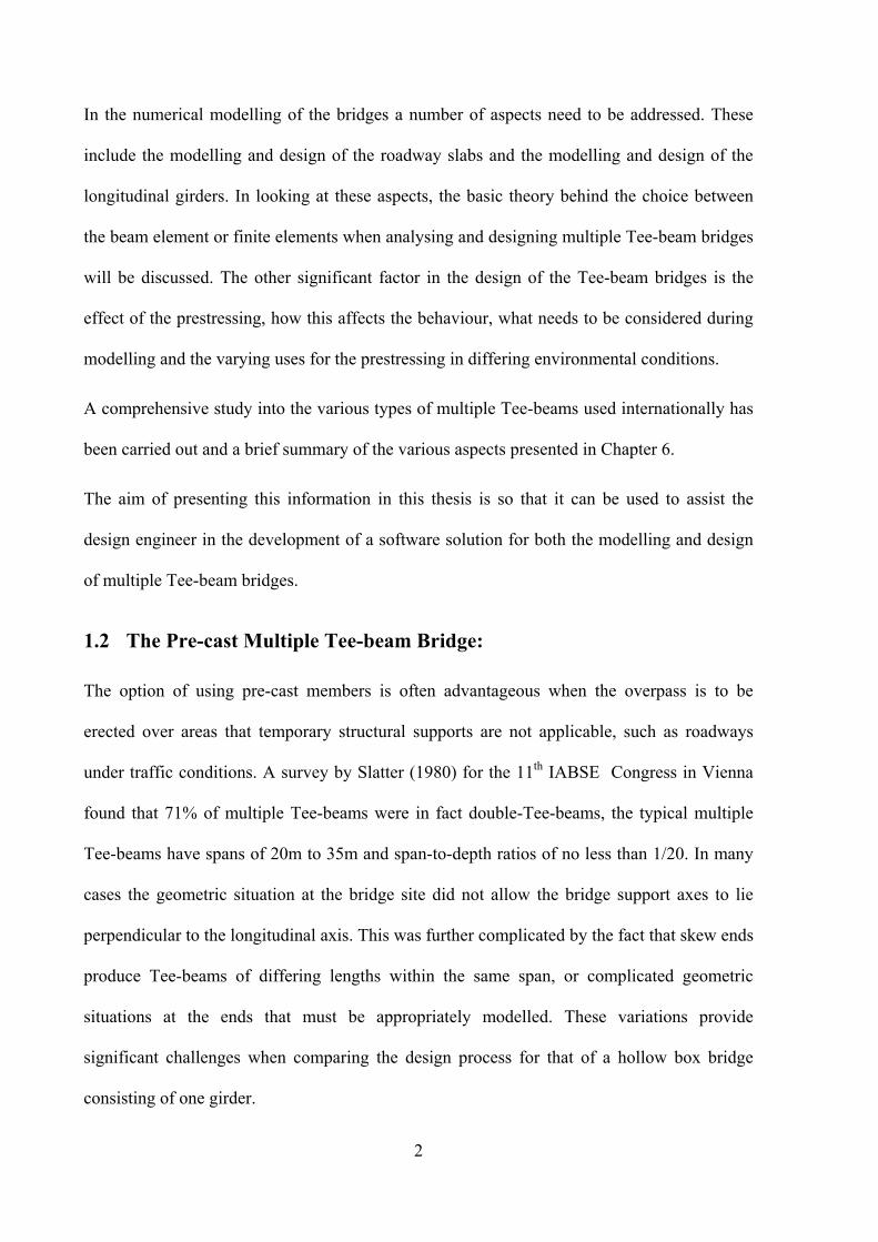
Multiple Tee-beam bridges built as pre-cast girders are usually produced in plants using high
grade concrete under controlled conditions, this generally results in higher-quality products
with longer life expectancy. The added advantage is that using this method it is possible to
cast the entire structure in the plant and transport it to the site for an erection as a whole. This
method was used for the construction of the 24 mile Lake Pontchartrain Bridge near New
Orleans, Louisiana, US. Shown in Figure 1-2 this bridge is considered to be the longest bridge
in the world, with numerous spans each 19.0m long and 11m wide, pre-cast in a yard and
floated for final erection.
Figure 1-2. Lake Pontchartrain Bridge near New Orleans
1.3 History of pre-cast pre-stressed beams:
The first pre-stressed pre-cast girders date back to 1886 when P.H. Jackson patented the
system in San Francisco, California. In 1888 the German engineer C.E.W. Doehring
independently obtained a patent for pre-stressed concrete slabs with metal wires.
However, these early attempts were not successful because the pre-stressing losses due to
creep and shrinkage of the concrete were significant. The credit for successfully developing
the modern concept of pre-stressed concrete goes to the French engineer Eugene Freyssinet,
who demonstrated the usefulness of pre-stressing using high-strength steel to control pre-
stressing losses in 1941 [Steinman and Watson, 1957]. Freyssinet started in 1941 with a 60m
4
segmentally constructed, two-hinged, portal-framed bridge over the Marne in Luzancy in
France and followed by five other nearly identical bridges, Freyssinet proved the effectiveness
of pre-stressed concrete as a new building material.
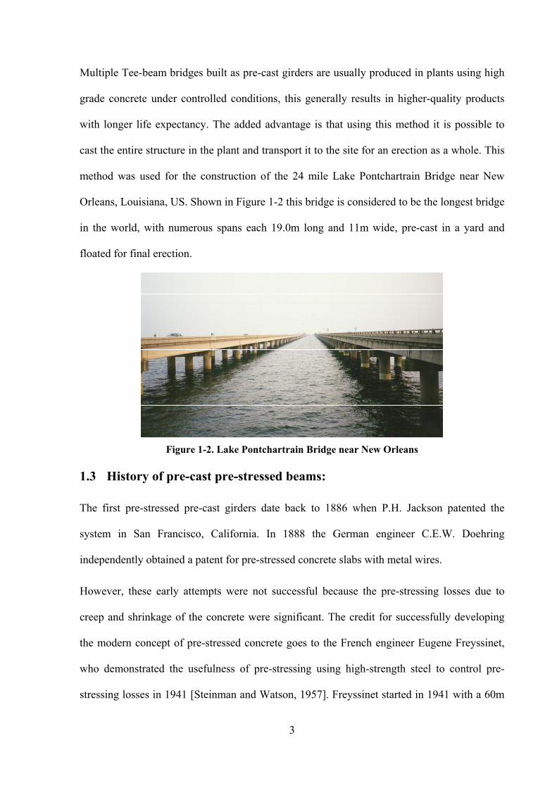
In the US the first major pre-stressed concrete bridge was the three span (25, 54, 25m) precast
pre-tensioned Walnut Lane Memorial Bridge in Philadelphia, Pennsylvania [Schofield, 1948].
Figure 1-3 and Figure 1-4 show different views of the bridge which is still in service after a
general renovation in 1993. Following its construction the Bureau of Public Works, now the
Federal Highway Administration (FHWA) published “Criteria for Pre-stressed Concrete
Bridges” which was revised in 1954. This can be considered as the first design code for this
type of construction.
Figure 1-3. Overall view of the Walnut Lane Bridge in Philadelphia, Pennsylvania.
Since then pre-stressed concrete bridges have been progressively replacing reinforced
concrete bridges and steel girder bridges as the choice in the small and medium span bridges.
According to the National Bridge Inventory (NBI) pre-stressed concrete bridges are the most
commonly built bridges today, almost 50% of all bridges built in the USA are of this type
[Dunker and Rabbat, 1990]. Consequently, the authorities in most states in the US have
developed specific rules and guidelines for the use of this bridge type. Today the name

5
“AASHTO” girder is a common expression for pre-cast and pre-tensioned bridge in Asian
countries.
Figure 1-4. Support detail of the Walnut Lane Bridge in Philadelphia, Pennsylvania.
The examples for the use of multiple Tee-beams are numerous and the method of using pre-
cast beams has been brought to new level producing spectacular structures. The following
figures show a selection of bridges illustrating that although the span length is limited when
using pre-cast beams the resulting bridges can be architectural pleasing and big in size.
Figure 1-5. Confederation Bridge in Calgary.
Opening for traffic June 1997, the Confederation Bridge (See Figure 1-5) links New
Brunswick to Prince Edward Island across the Northumberland Strait. It is currently the
6
longest bridge in the world to cross ice-covered salt water. All the beams and piers were pre-
cast on site. At 12.9 km in length the Confederation Bridge was planned and designed in
Calgary with strong links to the University of Calgary. The design also included onsite
evaluations of ice loads, wind loads and ship impact.
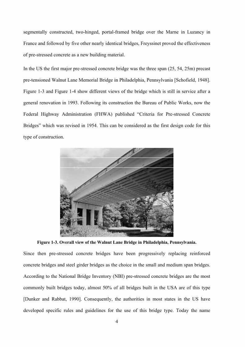
Figure 1-6. Kien Cable Stayed Bridge in Vietnam near Hanoi.
A more recent example of a large Tee-beam bridge is the Kien - Bridge in Vietnam (see
Figure 1-6). For this project pre-cast beams have been used for the approach spans. The
Bridge near Hanoi was completed in 2005.
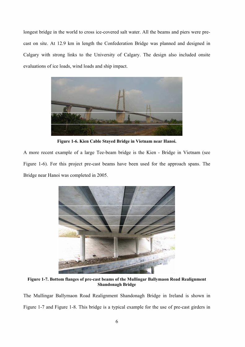
Figure 1-7. Bottom flanges of pre-cast beams of the Mullingar Ballymaon Road Realignment
Shandonagh Bridge
The Mullingar Ballymaon Road Realignment Shandonagh Bridge in Ireland is shown in
Figure 1-7 and Figure 1-8. This bridge is a typical example for the use of pre-cast girders in

7
bridges with no specific aesthetic requirements. The support axes are skew, the bridge is
almost as wide as the span. In this case the use of a different erection sequence would have
been difficult regarding the installation of formwork over the river.
Figure 1-8. Skew support axes of the Mullingar Ballymaon Road Realignment Shandonagh
Bridge
The Mullingar Ballymaon Road Realignment Shandonagh Bridge is a 3 span structure with
pre-cast beams spanning all three spans.
Typically the pre-cast beams are of lengths equal to the spans, this is the case for the Pont
d’Ouche in France (see Figure 1-9) For the Pont d’Ouche bridge the ends of the beams lie on
the support structures as shown in Figure 1-10. The slab however is continuous which is
achieved by an additional pre-stressing passing through over the support and through the cast
in-situ slab, a procedure which is discussed in Chapter 4.

8
Figure 1-9. Overall view of the Pont d’Ouche structure in France.
Figure 1-10. Support detail of the Pont d’Ouche structure in France.
A slightly different example is the CPCI bridge in Spain shown in Figure 1-11. The bridge
represents a construction method that uses two different types of pre-cast beams in the one
bridge structure. The first and third beam overhangs the span by 2/10 into the adjacent spans,
the second span is therefore a different type being much shorter that drops between and rests
on the adjacent spans.
9
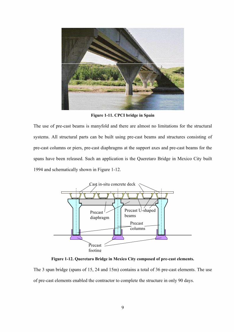
Figure 1-11. CPCI bridge in Spain
The use of pre-cast beams is manyfold and there are almost no limitations for the structural
systems. All structural parts can be built using pre-cast beams and structures consisting of
pre-cast columns or piers, pre-cast diaphragms at the support axes and pre-cast beams for the
spans have been released. Such an application is the Queretaro Bridge in Mexico City built
1994 and schematically shown in Figure 1-12.
Precast
footing
Precast
columns
Precast
diaphragm
Precast U-shaped
beams
Cast in-situ concrete deck
Figure 1-12. Queretaro Bridge in Mexico City composed of pre-cast elements.
The 3 span bridge (spans of 15, 24 and 15m) contains a total of 36 pre-cast elements. The use
of pre-cast elements enabled the contractor to complete the structure in only 90 days.

10
1.4 Advantages and disadvantages of pre-stressed girders
The multiple Tee-beam structure is a very popular application for the use of pre-cast beams
with cast-in-situ concrete slabs. The pre-cast beams can be prepared in a convenient way in
specific castings yards. When considering the use of this type of structure the following
advantages and disadvantages should be considered.
1.4.1 Advantages of pre-cast pre-stressed girders.
• The members may be cast in a controlled environment and then moved to site
allowing tight construction tolerances.
• The system of pre-cast beams and cast in situ concrete deck are quick and easy to
erect.
• The pre-stressing has the advantage that tension cracking can be eliminated in a pre-
stressed structure. The uncracked structure leads to a more efficient design than that
from conventional reinforced concrete members.
• Prestressing permits a more efficient use of concrete as a structural material because
the entire section, not just the uncracked section, is made to resist compression.
• Pre-stressing reduces the diagonal tension. Use of inclined tendons reduces the shear
carried by the webs, thus producing lighter sections and thus savings in transportation
costs and increases the bridge efficiency.
• The smaller girder depths that are possible with pre-stressed concrete members.
• Pre-stressed concrete girders with large top flanges provide working space during
erection und minimize the need for falsework.
• Pre-stressed concrete have relatively longer service life as outlined by Jerzy Zemajtis
(1998).

11
1.4.2 Disadvantages of pre-cast pre-stressed girders:
• Cast in-place post-tensioned structures are adaptable to complex geometries involving
curved, superelevated, skewed, multilevel sections.
• Varying section depths are difficult to achieve in a casting plant.
• The span length is limited to max 50m.
• Transportation needs to be considered with it being necessary to have good access to
the bridge sites by either by road or water access.
• Aesthetically pleasing shapes are limited, with the geometry and spans limited by the
casting yard.
1.5 Transportation and Construction Considerations
The dimensions of the pre-cast beams are generally defined by two parameters the length and
cross-section. Typically a maximum length of up to 40m can be transported with trucks (both
weight and length are an issue), while the cross-section including the width and height give
limitations on the design of the pre-cast beams.
While not used extensively, the multiple Tee-beams do not have to utilise pre-cast beams, but
may also consist of cast in-situ bridges. While these bridges are outside the scope of this
thesis Figure 1-1 shows a typical example where the geometry given i.e. the widening of the
deck in this case, does not allow for the easy use of pre-cast beams thus cast in-situ is a viable
alternative. Another example of this type of bridge is the Muuga bridge in Estonia shown in
Figure 1-13. The bridge completed in 2005 was erected using the span-by-span erection
sequence with the deck and tee-beams all cast in-situ.

12
Figure 1-13. Formwork of the Muuga Bridge in Estonia
The majority of the multiple Tee-beam bridges utilise the cast and transport technique. A
good example of where the pre-cast members were advantageous is the Katharine River
Bridge in Australia as shown in Figure 1-14 For this bridge girders were cast in the casting
yard (see Figure 1-15) and then transported to the remote location of the bridge and put in
place.
Figure 1-14. Placing final span Katherine River Bridge July 2002

13
Figure 1-15. the pre-cast beams used for Katherine River Bridge.
1.6 Assumptions for the geometry of Multiple Tee-beams
All bridge structures have a three-dimensional geometry and any structural model set up for
the analysis must reflect this. The simplifications into two-dimensional models often neglects
important effects and are therefore not appropriate, or conservative assumptions are made to
approximate effects thus giving ineffective structures. A modern software tool for bridge
engineers should provide the means to define a detailed 3-D representation of a given bridge
structure that models all geometric and material effects. In order to model the exact geometry
of a multiple Tee-beam bridge attention must be paid to a number of important details.
The plan view and the elevation of such bridges are governed by the specific geometric
requirements of the road alignment; these requirements have repercussions on the cross-
section along the bridge. A cross-fall of the road slab leads to inclined top slabs and the
possibility of Tee-beams with different height levels. Additionally, skew ends are often found
in such bridges and attention must be paid to model these support conditions correctly as
detailed later. These geometrical requirements often have significant structural effects and
should all be considered in an appropriate structural model. Furthermore, the modelling of the

14
geometry of off-ramps and road widening also poses challenges to the development of an
accurate model.
The difference between the actual cross section geometry and the cross section geometry in
the model represents another source of potential modelling error. All cross sections of bridges
have a cross fall, while it is common practice to consider the cross section as being perfectly
flat. This simplification is shown in Figure 1-16.
Actual cross
section shape
Simplified cross
section shape
Axis for
water drain
Actual cross fall
of cross section Flat cross section for
simplified model
Figure 1-16: Real cross section with cross fall and simplified cross section for structural model
As a consequence some of the non-symmetric behaviour of the bridge will not be modelled. A
similar problem occurs for vertical alignment, the longitudinal slope is in most cases not
considered when modelling the bridge deck. The typical longitudinal slope is in the range of -
5% < slope < +5% and the effect on the structural analysis can be neglected. When the slopes
exceed these limits, then the slope should be a consideration within the structural model as
detailed by Arthur Nilson (1978). The simplification however can be crucial since dimensions
such as span length get changed as shown in Figure 1-17.

15
Rounding“R“ Longitudinal slope
Longitudinal slope
Tangent point
Structure considered
flat for overall analysis.
Figure 1-17. Vertical alignment of bridge deck.
1.7 Multi-Span Pre-cast Tee-Beams
The most common way of assembling multi-span Tee-beam bridges is to use simply
supported pre-cast Tee-beams supported between piers then connected by a cast in-situ
concrete slab. The casting sequence of the concrete slabs is often geared towards reducing the
locked-in stresses in the final composite system. Shear connectors between pre-cast beams
and concrete slab ensure that forces are transmitted fully between the slab and the pre-cast
components.
In Australia, the “Super-Tee” system is an example for this method, these bridges are widely
accepted by the industry as the most efficient means of construction for most bridges and
consequently the design follows proven standard procedures. These design procedures are
based on a number of assumptions and it is possible to improve the efficiency of the structures
by utilising existing modelling software, but in developing the model the designer must
consider the following effects:
• The change in structural system at the piers where the pre-cast beams are simply
supported and made partially continuous by the concrete slab at a later time. Full
continuity can be achieved by installing diaphragms at the piers.

16
• Differential creep and shrinkage in the individual parts of the concrete-concrete cross-
section.
• Change in cross-section properties including the shift in the centre of gravity due to
the addition of the concrete slab.
1.8 Erection Procedures
While not discussed in detail in this thesis it was thought prudent to include a brief outline of
the erection procedure to obtain an overall understanding of all considerations for this type of
structure. When dealing with pre-cast elements and in particular with multiple Tee-beams an
important design considerations is the erection sequence.
1.8.1 Typical erection procedures
There are two principle erection methods for multiple Tee-beam structures: either as cast in-
situ bridges, (see Figure 1-13), or the erection as composite structures consisting of a number
of pre-cast beams with a cast in-situ concrete deck (see Figure 1-7). The most economical
system is the pre-cast beams used with the cast in-situ concrete for the roadway deck/slab. In
this case the cross-section consists of parts with different concrete quality and different
concrete age resulting in a composite cross section.
1.8.2 Erection of pre-cast beams:
Generally speaking the erection procedure is dependent on the design engineers and the
constructor. However, some regulatory bodies do give clear advice of how pre-cast Tee-beam
bridges are to be erected.

17
Figure 1-18. Typical construction sequence for 2 simply supported pre-cast beam (proposal
from Washington State Department of Transportation, US)
A typical example of this is the Washington Department of Transportation, in which they give
guidelines for the construction of single span simply supported bridges with pre-cast beam.
They also provide guidelines for two span simply supported and continuous bridges with pre-
cast beam bridges. Figure 1-18 demonstrates Washington Department of Transportations
requirements for the erection of multiple simple supported pre-cast girders, also provided are
the times to be considered when adding load to the system.
As comparison also included in this document are the guidelines for the bridge that is
continuous over the centre support. In Figure 1-18 the continuity over the supported is not
achieved, while there is a cross beam closing the gap between the ends of the pre-cast
girder,

18
Figure 1-19. Typical construction sequence for 2 span continuous pre-cast beam (proposal from
Washington State Department of Transportation, US)
but there is no reinforcement or pre-stressing passing over the support for creation of a
continuous girder. However, in Figure 1-19 a similar procedure is shown, but in this case the
guidelines allow for a layer of reinforcement passing over the support cross girder creating a
continuity over the support.
1.8.3 Erection of cast in-situ Tee-beam bridges:
The most frequently used erection method when casting multiple Tee-beam bridges on site is
the span-by-span method as shown in Figure 1-20. Each span is cast individually often with a
cantilever in the adjacent span to reduce the sagging moment in the span thus economising the
required cross-section.

19
My span1 = My summation
My span2 My summation
My summation
My summation
My span3
My span4
Age 1
Age 1 Age 2
Age 1 Age 2 Age 3
Age 2 Age 1 Age 3 Age 4
Figure 1-20. Span-by-Span erection and development of bending moment My.
When the bridge cast in-situ, creep and shrinkage play a significant role in the structure and
have a tendency to change the forces within the structure. Consequently the designer must
consider the implication of each stage of these effects to minimise any detrimental effects.
Figure 1-20 also shows how the bending moment changes during the various stages of
construction considering self weight only.
A combination of both pre-cast and cast in-situ methods is also be found in practise and the
methods and possible variants are numerous and well outside the scope of this thesis.

20
1.9 Codes requirements for design of multiple Tee-beam bridges
All international design standards require that any structure be checked under both
serviceability and ultimate strength conditions. Several criteria must be met, these include
stress limits and maximum deflection, and all structural components with in the structure need
to be designed accordingly.
The challenging goal to all engineers is to find the best possible solution. Consequently, it is
common that a number of iteration occur as the optimum solution is found considering
quantities, costs, aesthetics and feasibility.
Once the basic parameters such as span length and cross-section shapes are defined the design
cycle for a typical pre-stressed multiple Tee-beam structure is as follows:
1.9.1 Internal forces:
Determine all relevant internal forces due to all appropriate loading cases. These forces
are to be made available for each load case with and without multiplication factors for
later use in determining the worst load combinations.
1.9.2 The serviceability criteria:
For each national standard an allowable stress for the concrete under service load is
specified. The stress distribution is considered to be linear over the cross-section height
and the stresses for all relevant construction stages and load situations are checked on
the extreme fibres.
The serviceability check is also done for the tendons for which the actual stresses under
service load need to be evaluated and compared to the allowable steel stresses.

21
1.9.3 Ultimate moment capacity:
The strength in the concrete, pre-stressing tendons and reinforcements is reduced by a
partial factor for strength (some codes call it a material factor γm).
When calculating the ultimate moment capacity the cross-section internal equilibrium
considering all material components at their ultimate strength and the actual cross-
section internal eccentricities of all components relative to the neutral axis is
established. In Figure 1-21 the principle of the ultimate moment capacity calculation is
shown.
ε0
Stress σStrain ε My-int - internal capacity
My-ext – external load Cross-section
Reinforcement and pre-stressing tendons.
≥
Figure 1-21. Ultimate moment capacity and comparison to the external moment My.
1.9.4 Ultimate shear and torsion capacity:
Closely related to the shear stresses resulting from flexure in beams are those that are
the result of torsion action. Torsional shear stresses also produce diagonal tension cracks
in the concrete. Torsional reinforcement is similar to the shear reinforcement, and they
are then in many cases combined with each other since the shear stresses produced by
load actions are usually much below the direct shear strength of the concrete. The real
concern is with the diagonal tension stress in the concrete produced by shear stress
acting either alone or in combination with longitudinal normal stresses.

22
1.9.5 Longitudinal shear:
For the slab-web interface of composite decks such as pre-cast beams + cast in-situ
concrete slab the longitudinal shear needs to be checked and the structure needs to be
designed for.
1.9.6 Other checks:
Depending on the selected code additional checks are required such as fatigue and crack
width.
1.10 Summary
The analysis and design of multiple Tee-beam bridges requires the consideration of several
construction and design issues such as construction stages, change of structural system, time
dependent effects, combination of both pre-and post-tensioning and a sophisticated 3
dimensional structural model. For the engineer the amount of work and the aspects to be
considered are not much different compared to the design work for a long span balanced
cantilever bridge. This stands in contradiction to the relatively easy and quick erection of
multiple Tee-beam bridges.
The following chapters will highlight issues for design and construction for multiple Tee-
beams with a focus on pre-cast beams.

23
2 Loading
2.1 Introduction
The longitudinal Tee-beams in a multiple Tee-beam bridge can be assumed to display beam-
like behaviour in the longitudinal direction. This assumption implies that cross-sections of
these Tee-beams remain plane and undistorted. Therefore, vertical loading on these
longitudinal Tee-beams causes bending in the longitudinal direction and depending on the
location of the load the possibility of torsion. The roadway slab connects the individual
longitudinal members and is considered to be a structural link. The structural characteristic of
this roadway slab is that of a two-dimensional plate. Bending of the roadway slab in the
lateral direction causes torsion in the longitudinal girders and vice versa. The load-carrying
behaviour of the girder-slab system is governed by the combination of longitudinal Tee-beam
members with the connecting roadway slabs.
Loads acting on bridge structures cause internal forces in the structure. These internal forces
must be transferred to the foundations by the individual structural elements. Loads may act
directly on primary structural elements, such as the main girders in a multiple Tee-beam
bridge, or on secondary structural elements such as the roadway slab (Figure 2-1). In a
numerical structural model the loading occurring on the physical structure must be
approximated in a realistic way. It is common that the national design codes give guidance on
the particular nature of these load models. One common way of classifying loading types is
the differentiation between permanent and transient (or non-permanent) loads. The difference
between these loads is covered later in this chapter. Main girders of a multiple Tee-beam
structure therefore have two major load applications: firstly loads acting directly on the
girders; and secondly, loads being transferred to the main girders by secondary structural
components, ie. the roadway slab.
24
Loading on
roadway slab
Loading on
main girder
Figure 2-1. Loading on primary and secondary bridge deck components.
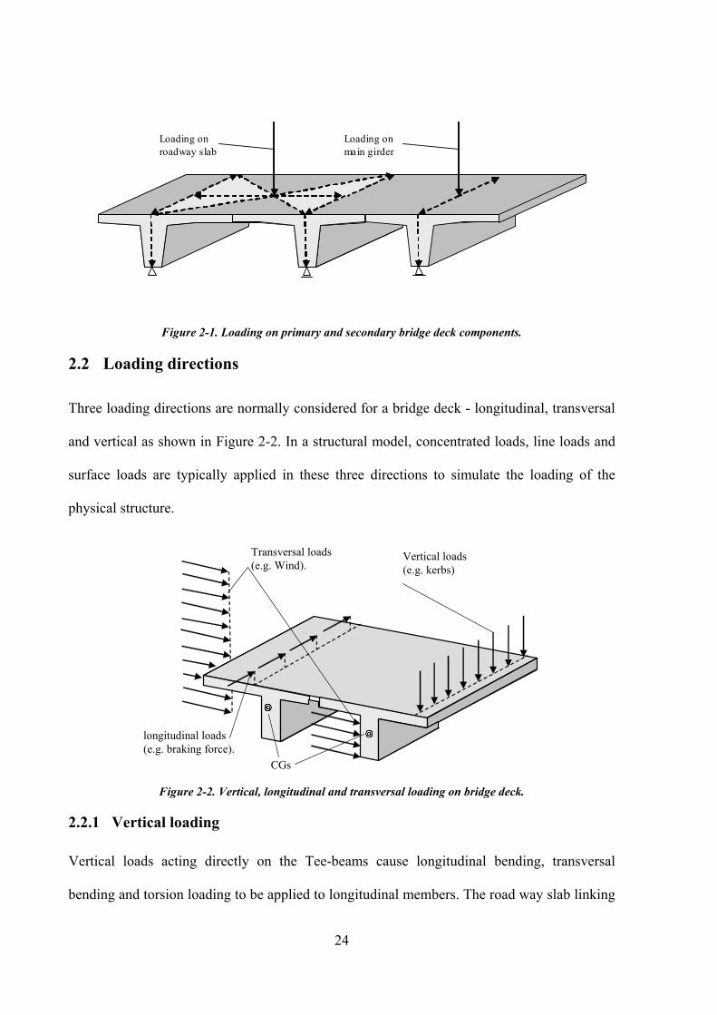
2.2 Loading directions
Three loading directions are normally considered for a bridge deck - longitudinal, transversal
and vertical as shown in Figure 2-2. In a structural model, concentrated loads, line loads and
surface loads are typically applied in these three directions to simulate the loading of the
physical structure.
longitudinal loads
(e.g. braking force).
Transversal loads
(e.g. Wind). Vertical loads
(e.g. kerbs)
CGs
Figure 2-2. Vertical, longitudinal and transversal loading on bridge deck.
2.2.1 Vertical loading
Vertical loads acting directly on the Tee-beams cause longitudinal bending, transversal
bending and torsion loading to be applied to longitudinal members. The road way slab linking

25
the longitudinal members transfers the load to the adjacent longitudinal sections in the bridge.
Figure 2-3a shows a typical situation where a vehicle load acts on a member. The magnitude
of this load transfer to adjacent members depends the stiffness of the roadway slab and special
focus needs to be given to the correct modelling of the roadway slab during the analysis and
design process.
Loading on the roadway slab between the longitudinal girders causes the slab to deflect
(Figure 2-3b). This deflection causes the Tee-beam girders on either side to rotate which in
turn induces torsion into these longitudinal members. This transfer of the vertical loads also
causes longitudinal and transversal bending into transferred to the Tee-beams.
It should be noted that vertical loading can also induce transversal bending into the Tee-beam
girders when the principal axes of the girders are not perfectly vertical – ie. in non-
symmetrical cross-sections – or the alignment in plan is curved.
rotated
cross-section deflected roadway slab
Load – vehicle
l d
vertical and
transversal bending
rotated and
translated
Tee-beam
cross-section
Bending of
roadway slab
(a)
(b)
Figure 2-3. Load transfer between Tee-beams.
2.2.2 Transversal loading
Transversal loading such as wind load or centrifugal forces due to traffic impose transversal
bending on the bridge deck as a whole. For this loading condition the roadway slab can be viewed

26
as a stiff member (eg shear wall) connecting the individual longitudinal members and distributing
the horizontal load to all longitudinal members. The horizontal loads acting away from the shear
centre of the Tee-beams again introduce torsion into the longitudinal beams. The roadway slab
deflects and transfers this torsional action from one Tee-beam to the other. This behaviour of the
bridge deck is sometimes approximated by modelling the shear wall effect with a Vierendeel truss
as shown in Figure 2-4.
2 longitudinal beams and
series of one-element cross
beams – Virendel truss
3 longitudinal beams and
series of two-element cross
beams – Virendel truss
MG1
MG2
MG1
MG2
MG3
Horizontal uniform load
Figure 2-4. Grillage under horizontal load acting as a truss with rigidly linked members (Vierendeel – truss).
Transverse bending moment obviously occurring under the described transversal loading condition
is often accompanied by torsion due to eccentricities of the load resultant in relation to the shear
centre. This torsional action on the Tee-beams causes bending in the roadway slab which in turn
transfers this torsional effect to the neighbouring longitudinal girders.
2.2.3 Longitudinal loads
Forces acting in the longitudinal direction of the bridge are especially important with regards
to the design of the bearings. Additional, bending moments are introduced into the bridge
deck due to the vertical eccentricity of the load application points in relation to the CG. When
the piers are rigidly connected to the bridge deck the braking forces become a governing

27
factor for the design of the foundation since the lever arms of the bridge piers generate
significant moments at the foundation levels.
2.3 Permanent Loading
2.3.1 Self weight
Self weight is often a dominant component of the accumulated bridge loading and the
accurate consideration of this loading type in a structural analysis is of great importance. The
self weight of the structural components can be computed easily by multiplying the volume of
these components with the specific weight of the associated material. For modelling reasons,
some overlaps between various structural elements may exist in a computer model and care
must be taken that the loading model is not doubled-up in the overlapping regions.
Additionally, the self weight of non-structural bridge components must be considered. These
loading items are often applied on the actual structure as surface loads (eg. pavement), line
loads (eg. barriers) or concentrated loads (eg. lamp posts). Self weight of the actual structural
components and additional dead loads are often grouped together individually to account for
different impact factors where applicable.
2.3.2 Time-Dependent Effects
Time-dependent deformation of concrete resulting from creep and shrinkage is of crucial
importance in the design of pre-stressed concrete structures. Partial loss of pre-stressing force
and significant changes in deflection and stress distribution are often caused by these time-
dependent effects
Creep strain for concrete has been found to depend on time, on the mix proportions, humidity,
curing conditions and the loading history of concrete among others (CEB/FIP (1990)). Creep
strain is nearly linearly related to stress intensity. It is therefore possible to relate the creep
strain to the initial elastic strain by a creep coefficient. Typical values of the creep coefficient

28
range from about 1.6 to 3.2, the lower coefficient corresponds to the higher concrete
compressive strength. In pre-stressed concrete members the compression causing creep varies
over time because of relaxation of steel pre-stressing stress, shrinkage of the concrete and
member length changes associated with creep itself. This interdependence can be adopted to
lead to a step-by-step approach in calculating time dependent losses in which stresses acting
at the beginning of a specific time interval, causing the next increment of deformation reflect
all losses that have occurred up to time (Pircher 1994). For the present purpose losses are
treated individually in order to appreciate the role of each effect. Practical calculations are
often carried out on this basis as well. For pre-cast members, that later are connected to a cast
in-situ slab the moment of inertia of the composite section should be used in calculating the
stress caused by loads applied after the cast in-situ concrete has hardened.
Creep calculation according to the CEB/FIP (1990) require a careful handling of system data.
The following short example should illustrate the amount of data. Figure 2-5 shows the
development of the creep coefficient φ for a structure being erected in 3 construction stages.
The graph shows only one element of the structure. At the time of first load application, the
starting time for creep, the concrete is 14 days old. For this element for the first stage a creep
coefficient φ14 results. The coefficient changes during the stage 1 over a time of 28 days. At
the end of stage 1, new elements are added to the structure and new loads applied (PT = pre-
stressing, SW = self weight). Due to these new loads a new creep coefficient for the same
element needs to be determined. The two creep coefficients for one element now require
monitoring and undergo further changes as the structure changes. After new elements and
new loads are applied to the structure in stage 3 the previously existing creep coefficients are
changed again and a third one for this element is added. This procedure needs to be done for
all elements in a structure and for all ages and all loading cases if the analysis is to comply
with CEB/FIP (1990).

29
-42 -14 0 28 56 77 10077
Stage 1 Stage 2 Stage 3
REFERENCE – TIME AXIS [Days]
Element X 14 Days
Creep coefficient t
tcurrentl
..... 0ϕ
Stage 1 Stage 2 Stage 3
14ϕ
[ ϕ ]
Figure 2-5. Creep coefficient changes during construction stages.
Shrinkage of concrete causes a reduction of strain in the pre-stressing steel equal to the
shrinkage strain of the concrete. The resulting steel stress loss is an important component of
the total pre-stressing losses for all types of pre-stressed beams.
For pre-tensioned construction pre-stressing often takes place as early as 24 hours after
casting and a high percentage shrinkage may therefore affect pre-stressing losses. Post-
tensioned members are less affected since pre-stressing is usually applied at a later stage
(Nilson 1987).
2.4 Additional loading
2.4.1 Wind loading
Wind loading is often approximated as lateral surface loading acting on the exposed side-
areas of the deck with amplification factors on the static loading to account for the dynamic
nature of wind gusts. Many design codes consider various wind loading cases for different
situations – eg. wind loading for the deck with traffic on the bridge, and wind loading without
traffic, or wind loading with different wind velocities for different load combinations. If the
cross section depth varies along the length of the bridge the resulting lateral load has a

30
longitudinal variation that needs to be considered. Oftentimes wind loading is assigned to the
longitudinal Tee-girders directly with loading acting on all exposed webs. It is important to
note, that depending on the consideration of traffic, the distance of the resulting load vector to
the shear centre varies and that torsional moments may be introduced by wind loading. The
described loading model is a strongly simplified approximation which neglects dynamic
effects and probabilistic properties of this type of bridge loading. However, the spans of
multiple Tee-beam bridges are typically sufficiently small to make the described
simplifications acceptable for design purposes.
2.4.2 Traffic Loading
As with all other loading types the exact nature of a traffic loading model for a particular
country is determined by the respective national design code. However, some general
characteristics common to most of these codes can be summarised in the context of this
chapter.
The actual loading is usually given by the definition of loading vehicles, mostly consisting of
a series of concentrated wheel loads. These loading vehicles are often combined with
distributed loading components. Some codes (eg. British standards BS5400 (1990)) require a
variation of loading intensity depending on the loaded length of a girder based on the shapes
of the influences lines and the influence surfaces. Other codes introduce variabilities in the
distances between the individual concentrated wheel loads (eg. Australian Standard AS5100,
AS 2004). Traffic loading usually applies in all three mentioned directions; vertical loading
due to the weight of the passing vehicles, and longitudinal loading to account for forces
generated by braking of vehicles and transversal loading to simulated centrifugal forces
occurring on curved bridges.

31
The location of traffic loading is usually driven by the setup of traffic lanes on the bridge
deck. Some codes allow the placement of the wheel loads along the centre line of a given
traffic lane (DIN1045 (2004)), other codes require the exact two-dimensional positioning of
the individual wheel loads (BS 5400 (1990)).Traffic loads act on both the main girders
directly and on the roadway slab depending on the setup of the traffic lanes in relation to the
centre lines of the Tee-beams.
The most detrimental position for the placement of one or more loading vehicles within a
given lane can then be determined for each member from the result matrix. It should be noted
here that the governing traffic position for one design force often differs from the governing
traffic position of another design force. This fact complicates traffic load evaluations in
structural analysis and design situations.
Results for the loading of individual lanes are combined to give the result envelopes for the
complete bridge deck. Design codes give combination factors for these lane combinations
which are based on probabilistic assumptions.
Railway bridges commonly have fewer traffic lanes than road bridges and are generally with
predefined alignments, but the loading magnitudes for railway bridges are significantly
higher.
2.4.3 Temperature Loading
Temperature loading is commonly represented by combinations of three different load cases:
constant temperature change of the whole deck, linear temperature gradients along a vertical
cut through the deck, and non-linear gradients in the same direction. Some design codes
specify different gradients for enclosed areas such as box-sections and plates (NZS 3100
(1995)) while other codes do not require the consideration of non-linear gradients (BS5400
(1990)).

32
In composite cross-sections the designer must consider that even a constant temperature
loading causes bending in the bridge deck if the expansion coefficients of the materials of the
cross-section are different.
Non-linear temperature distributions as shown in Figure 2-6 cause a theoretical dilemma since
many design codes are based on considerations based on beam theory. Beam theory however
postulates to remain plane with a linear strain distribution which stands in direct opposition to
the assumption of a non-linear temperature distribution. This dilemma is often quietly
circumnavigated by turning the non-linear temperature distribution into an “equivalent” linear
distribution.
Figure 2-6. Linear and non-linear temperature distributions
2.4.4 Settlement
Geological and code-specific data usually determines the assumptions of the extent of
settlement to be taken into account in a structural analysis for each foundation in a bridge
structure. Design codes also give different specifications with regards to the combination rules
for settlement at individual foundation points within a bridge structure.
For continuous girders hogging moments can be introduced in the deck above piers. These
hogging moments can become an important design issue when combined with pre-stressing
which also causes hogging above the intermediate support points.

33
For straight series of simply supported beams uneven settlement only causes displacements
but no stresses. However, uneven settlement in simply-supported bridges with skew piers or
curved alignments cause considerable stresses in the deck as illustrated in Figure 2-7.
Skew support
axis – twisted
roadway slab.
MG2
MG1
MG2
MG1
Bending moment due
to pier settlement.
Figure 2-7. Twist of roadway slab due to pier settlement for skew support axis.
The typical shape of the moment diagram due to pier settlement is shown in Figure 2-8. For
each pier an individual loading case is calculated. All loading case results together give the
envelope representing the most unfavourable situation of all possible settlements. The
individual loading cases are combined according to the relevant design code definitions. Some
codes allow only one settlement at a time, other require considering the possibility that several
piers settle simultaneously.
Loading case
combination –
min/max My
envelope.
Settlement
Pier 4. Settlement
Pier 3.
Settlement
Pier 2. Settlement
Pier 1.
Figure 2-8. Bending moment for pier settlement and secondary PT.

34

35
3 Pre- and post-tensioning
Concrete is utilised in structures as it exhibits excellent behaviour in compression, but in
tension it is left floundering. The use of pre-stressing can ensure that concrete members
remain within their tensile and compressive capacity thus increasing their versatility. The
development of pre-stressed concrete has resulted in greater flexibility in the selection of
bridge types and in the construction techniques utilised for bridges. Pre-stressed concrete is
frequently chosen for bridges with spans ranging from 20m up to 350m (Hewson 2000).
The following chapter describes some principles of pre-stressing, the application and the basic
considerations for handling the pre-stressing effects in the design of multiple Tee-beam
bridges.
• Pre stressing – principles and materials.
• Full and partial pre-stressing.
• Development length of pre-stressing strands
• Time dependent behaviour
• Primary and secondary effects.
• Consideration of pre-stressing for SLS and ULS design code checks.
• Precamber and application for pre-cast pre-tensioned members.
3.1 Pre-stressing – principles, materials and applications
Pre-stressing of concrete members is achieved by the transfer of stress from pre-stressing
tendons to the surrounding concrete. Tendons are placed within the concrete members as
either grouted internal tendons or as external tendons. It should be stressed that the geometric
position of the tendon within the cross-section is of great importance for the design.

36
Consider a simply supported pre-stressed beam with a rectangular cross-section. A pre-
stressing tendon is placed in the centroidal axis and stressed the force F, as shown in Figure
3-1. This beam is also loaded by a uniformly distributed load. The tensile pre-stressing force
in the tendon produces a balancing compressive force in the concrete. In the case illustrated,
the pre-stressing force is acting in the CG of the cross section and the stresses in the extreme
fibres are given by
I
My
A
F ±=σ (3.1)
In this case the stresses in the bottom of the member are less than those calculated at the top
of the cross-section.
Concentric tendon
Pre-stressing Force F
Uniform load e.g. self weight
Anchor plates
and tendon
Stresses due to
pre-stressing
Stresses due to
external load
Stresses due to pre-stressing
and external load
I
My
A
F ±=σ
A
F=σ
Figure 3-1. Stress distribution in a concentrically pre-stressed girder.
If the tendon is now placed with an eccentricity (e) to the CG of the cross-section as shown in
Figure 3-2 the pre-stressing force (F) is applied. To calculate the stress the same components
as in Equation 3.1 are utilised but the eccentricity also introduces a bending moment into the
girder and the resulting stresses in the extreme fibres are given by

37
I
My
I
Fey
A
F ±±=σ (3.2)
Unlike the concentrically stressed member the stresses in the bottom of the member are now
greater than those calculated at the top of the cross-section.
Eccentric tendon
Pre-stressing Force F
Uniform load e.g. self weight
Anchor plates
and tendon
Stresses due to
pre-stressing Stresses due to
external load
Stresses due to pre-stressing
and external load
CG of cross-section
Stresses due to
pre-stressing
eccentricity
I
My
I
Fey
A
F ±±=σ
Figure 3-2. Stress distribution in an eccentrically pre-stressed girder.
The required strength of the concrete is determined by the compressive stresses generated in
the concrete by the pre-stressing and applied forces. A minimum strength of fcu equal to
45N/mm2 is typical for pre-stressed concrete, however it is more common to use higher
strengths with a fcu up to 60N/mm2
(Ryall et. al. 2003). Even higher concrete is used for
specific projects. At the time of pre-stressing a minimum strength of 30N/mm2 for the
concrete is often required although this might vary depending on the tendon and anchor
arrangements and the magnitude of the applied load. To minimize the losses due to creep and
shrinkage, and thus losses in the pre-stressing, care is required in the mix design and the
water/cement ratio of the concrete should be kept to a minimum.
The stressing is achieved using high tensile steel in use as wire, bars or strands. The nominal
tensile strengths of these components vary between 1570N/mm2 and 1860N/mm
2 for wire and

38
strands and between 1000N/mm2 and 1080N/mm
2 for bars. Once the stressing load is applied
steel relaxation occurs, this results in the reduction of stresses in the tendons. The magnitude
of relaxation varies depending on the steel characteristics and the initial stresses. Typical
relaxation ranges from 2.5% to 3.5% when a stress of 0.70 fpu is applied. For an initial stress
of 0.50 fpu the relaxation reduces to about 1% (Ryall et. al. 2003).
When post-tensioning a concrete member the tendons may be grouted or un-grouted
depending on the design criteria. When cement grout is used it is pumped into the ducts to fill
the void in the ducts around post-tensioned tendons. Generally a water/cement ratio of
between 0.35 and 0.40 is typically used; admixtures are sometimes added to improve flow and
to reduce shrinkage. One of the major advantages of grouting is the protection of the tendons
from corrosion.
3.2 Full and partial Pre-stressing
When stressing a member two design methods are used either Full or Partial Pre-stressing.
The complete elimination of tensile stresses in members at normal service load is defined as
full pre-stressing. Early designers focused on this type of pre-stressing in order to avoid
cracks caused by tensile stresses on either side of the member. As experience grew solutions
between fully pre-stressed and reinforced concrete were often favoured. Such an intermediate
solution in which concrete receives tensile stresses which are compensated by reinforcement
is called partial pre-stressing. The cracking due to tensile stresses under full service load is
usually small and disappears when reducing the load.
Typically the fully pre-stressed girders are heavy with large cross-sections, producing an
objectionable large camber at more typical loads than the value service load. Partial pre-
stressing tends to results in more economical solutions by reducing the amount of pre-
stressing steel. When designing for partially pre-stressed girders, the design code generally

39
nominates whether reinforcement in the appropriate layer may be considered for tensile
forces, or whether the partially stressed steel can be considered as passive steel, using the
additional capacity as being equivalent to reinforcement.
It has been observed that partially pre-stressed girders are more or less the state of the art in
almost all popular design codes. Certain codes, for example the Eurocode 2 (CEN 2002),
demand full pre-stressing for certain load situations and partial pre-stressing for other load
combinations. In the US partial pre-stressing is the most frequently used as pre-stressing
method.
3.3 Pre-stressing methods
There are two methods commonly used for pre-stressing members as shown in Figure 3-3:
pre-tensioning and post-tensioning. Pre-tensioned members (Figure 3-4) are typically
produced in a casting yard by stressing tendons between external anchorages before the
concrete is placed in the formwork between these anchorages. As the concrete hardens it
bonds to the steel, when the concrete has reached the required strength, the anchorages are
released and the pre-stressing force is transferred to the concrete. Only linear tendon profiles
can be achieved.
Post-tensioned members are stressed inside ducts after the concrete has hardened to the
required strength. The pre-stressing is applied through jacks against the ends of the concrete
member and the ducts are usually grouted. Hardening of the grout creates the bond between
tendon and girder. Tendons may be bundled parallel wires, stranded cables, or solid steel rods.
A typical post-tensioning arrangement can be seen in Figure 3-5 where the geometry follows
the anticipated moment distribution due to self weight and traffic loading. Stirrups are
installed in regular distances in longitudinal direction supporting the duct and guaranteeing
the duct and tendon position after casting and jacking.

40
13mm or 15mm strand Strand debonding at end. Pre-
tensioned
strand
Beam thickened at end for
anchor Multi strand tendons
Post-
tensioned
strand
A
A A - A
B
B
B - B
Figure 3-3. Typical pre-tensioned and post-tensioned beam.
Precast beam
Casting bed tendon
jacks Tendon
anchorage
Hold down force
jacks
Support
force
Figure 3-4. Straight and polygonal tendon layout for pre-tensioned beam.
Lowest point at
40% of side
span
Concrete cover
min.120mm
Grout vent.
Diameter of duct
Position at Pier:
Strands at bottom of duct
Duct internal tendon
eccentricity
Position in span:
Strands at top of duct
Duct internal tendon
eccentricity
Dead
anchor
Stirrups installed in
regular intervals
Stressing
R[m] = curvature
Figure 3-5. Typical post-tensioned tendon layout.
3.4 Development length of pre-stressing strands
Stresses are transferred from the pre-stressing strands to the surrounding concrete through the
bond between the two materials. The distance from the end of the member over which the

41
effective pre-stressing force develops is called the “transfer length”. The “flexural bond
length” is the additional bond length necessary to develop the strand stress from effective pre-
stress to the ultimate at the ultimate flexural strength of the beam. The sum of these two
lengths is called the “development length”. Kaar et. al. (1963) gives the following equation
for the development length.
DffDf
L sesuse
d )(3
* −+= (3.3)
The first term, (fse/3)D, represents the transfer length. The second term, (fsu-fse)D, represents
the flexural bond length. Some codes like the AASHTO (1996) require a minimum
development length for bond beyond the critical section given by
DffL sesud )3
2( * −= (3.4)
In both formulas D is the nominal strand diameter, fsu* is the average stress in the pre-
stressing tendon at ultimate load and fse is the effective pre-stressing steel force after all
losses. Research by Deatherage & Burdette (1991) showed that the transfer and development
length increase almost linearly with the strand diameter.
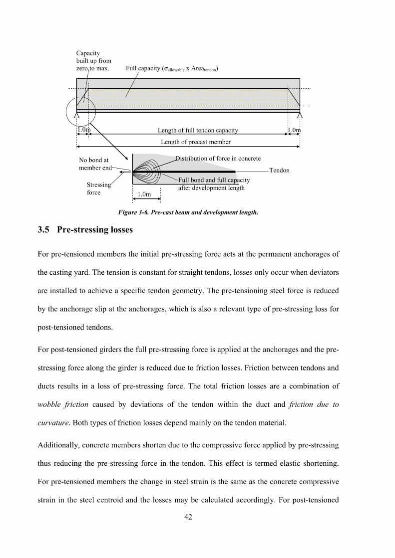
Pre-cast beams can be created in a controlled environment and usually have high concrete
quality and good precision in reinforcement layout and pre-stressing arrangement. Stress
transfer is often approximated by a linear function as shown in Figure 3-6. In pre-cast
members the anticipated moment diagram due to dead load and traffic loading is often
counteracted by groups of tendons which are sleeved in a staggered pattern towards the ends
of the members.
42
1.0m 1.0m
Length of precast member
Full capacity (σallowable x Areatendon)
Length of full tendon capacity
Capacity
built up from
zero to max.
No bond at
member end
Stressing
force 1.0m
Distribution of force in concrete
Full bond and full capacity
after development length
Tendon
Figure 3-6. Pre-cast beam and development length.
3.5 Pre-stressing losses
For pre-tensioned members the initial pre-stressing force acts at the permanent anchorages of
the casting yard. The tension is constant for straight tendons, losses only occur when deviators
are installed to achieve a specific tendon geometry. The pre-tensioning steel force is reduced
by the anchorage slip at the anchorages, which is also a relevant type of pre-stressing loss for
post-tensioned tendons.
For post-tensioned girders the full pre-stressing force is applied at the anchorages and the pre-
stressing force along the girder is reduced due to friction losses. Friction between tendons and
ducts results in a loss of pre-stressing force. The total friction losses are a combination of
wobble friction caused by deviations of the tendon within the duct and friction due to
curvature. Both types of friction losses depend mainly on the tendon material.
Additionally, concrete members shorten due to the compressive force applied by pre-stressing
thus reducing the pre-stressing force in the tendon. This effect is termed elastic shortening.
For pre-tensioned members the change in steel strain is the same as the concrete compressive
strain in the steel centroid and the losses may be calculated accordingly. For post-tensioned

43
members the elastic deformation of the concrete takes place after applying the jacking force
and there is automatic compensation for shortening losses. If parallel or overlapping tendons
are post-tensioned sequentially the interaction between the elastic shortening losses for each
tendon must be considered. Especially, in constructions where pre-tensioning and post-
tensioning are combined losses in the pre-tensioned steel occurring due to the post-tensioning
actions need to be accounted for.
Time-dependent effects also cause reductions of stress in the pre-stressing steel. Creep and
shrinkage in the concrete as well as relaxation for the pre-stressing steel contribute to this
group of losses.
Figure 3-7 shows the force distribution in a pre-stressing tendon considering losses due to
friction, wobble, anchorage slip, creep and shrinkage and steel relaxation in a post-tensioned
member.
All losses require consideration in the analysis and design process. The time dimension
becomes an important factor and needs to be incorporated in the calculation of pre-stressed
structures. The described losses do not happen simultaneously but at different points in time
as shown in Figure 3-8.
Jacking force
Initial jacking force
Losses due to
anchorage slip
Force in tendon
reduced due to
friction and wobble
Force in tendon at time of
completion reduced due to creep
and shrinkage and other PT action
in the structure
Force in tendon at time infinity.
Allowable steel stress
Maximum tendon force
Figure 3-7. Development of forces in the pre-stressing tendon.

44
Total pre-
stressing
losses
Shrinkage Creep
Steel
relaxation
Elastic
shortening
Friction
Anchorage
slip
Du
e to
co
nre
te
Du
e to
ste
el
Instantaneous Time-dependent
Causal relation
Effect relation
Figure 3-8. Interrelationship of causes and effects among pre-stressing losses [Naaman and Hamza, 1993]
3.6 Primary and secondary effects
When pre-stressing tendons apply load to the structure the resultant forces and moments
generated can be considered as a combination of primary and secondary (or parasitic) effects.
Primary effects are the moments, shears and axial forces generated by the direct application of
the force in the tendon on the relevant section. Secondary effects occur when the structure is
statically non-determinate and restraints on the structure prevent the pre-stressed member
from deflecting when the pre-stressing force is applied. For continuous decks the intermediate
supports restrain the deck from vertical movement and secondary moments and shear occur.
The combined primary and secondary affects as shown in Figure 3-9 are derived directly from
the analysis output. The forces and moments from the tendon are applied at each anchor
position. Along the structure equivalent loads are applied to the model wherever the tendon
geometry has a change of angle. Care needs to be taken when modelling the structure since
the example shows that the support definitions have a major influence on the behaviour of the
structure under pre-stressing load. The correct consideration of pre-stressing as well as the

45
subdivision of the pre-stressing results into primary and secondary effects is a basic
requirement for computer programs today (Bangash, 1999).
Typical prestress layout
Pre-stressing anchorage Tendon eccentricity e
Section neutral axis
Equivalent forces Load intensity =
Force in tendon
Radius of tendon
Fv
Fh Mp
Primary effects: Mp=P*e Secondary effects
Resultant moment: primary + secondary Hogging moment
Sagging moment
Figure 3-9. Pre-stressing – primary and secondary effects in a continuous girder
Figure 3-10 shows the principle of how the ratio between primary and secondary effects can
be estimated by comparing the areas between the tendons and the CG of the cross-sections.
However, this estimation does not consider the fact that the pre-stressing force is not constant
along the girder.
Due to the cross-section geometry of Tee-beams the CG of cross sections is geometrically
relatively high. This position of the CG becomes especially important when defining the pre-
stressing of the girder. The eccentricity of the tendon in the span relative to the CG is bigger
than the eccentricity at the support. When considering the example in figure 3-9 and
accounting for the eccentricity relatively high secondary moments result. In some cases the
secondary moments can be of the same magnitude as the primary moment which means that
the pre-stressing forces compensate each other.

46
The remaining structural design component to be considered is the axial force which causes
compression in the concrete. The secondary effects can be reduced by shifting the tendon
geometry closer to the CG. Increasing the distance to the bottom fibre in the spans decreases
the cross-section capacity.
Area between
tendon and CG in
spans (area A)
Area between
tendon and CG at
supports (area B)
Pre-stressing anchorage Tendon eccentricity e
Section neutral axis Rectangular
cross-section
Σareas B = Σareas A →Secondary effects = 0
Σareas B > Σareas A →Secondary effects are hogging
Σareas B < Σareas A →Secondary effects are sagging
Tendon eccentricity e
Section neutral axis Tee-beam
cross-section Area between
tendon and CG in
spans (area A)
Area between
tendon and CG at
supports (area B)
Primary effects: Mp=P*e Secondary effects
Resultant moment: primary + secondary
Hogging moment
Sagging moment
Tee-beam
cross-section
Σareas B << Σareas A →Secondary effects are sagging
Figure 3-10. Quick estimation of primary and secondary effects in a continuous girder for a rectangular cross
section and a Tee-beam.
3.7 Consideration of pre-stressing for SLS and ULS design code checks
At SLS the stresses in the concrete must be kept within allowable limits for both compression
and tension. It is usual to keep the concrete in compression across the full section under
permanent load and to allow tension stresses up to 2 - 3 N/mm2 for live loading. The primary
and secondary forces both combine giving the resultant force distribution as shown in Figure

47
3-11. The corresponding stress distribution in the cross-section is taken into account for the
SLS checks. In many design standards the Primary and Secondary effects require different
safety factors and therefore must be considered as separate entities.
+ =
Applied
force Primary
stresses
Secondary
stresses
Resulting
stresses
e
P
Figure 3-11. Stresses due to pre-stressing in cross-section
The moment of resistance, or capacity, at a section is derived by comparing the balance of the
tensile force in the tendons and reinforcement with the compressive force in the concrete. The
strain distribution is considered to be linear across the section with the point zero being the
effective neutral axis as shown in Figure 3-12.
fcTo
fcBottom
fctop
Stress Strain
Initial stress and strain distribution
fp fs εp εs
εcBottom
εctop
Stress and strain distribution at
ultimate moment of resistence.
Neutral axis Inner
lever
arm
0.67 fcu
fsAdditional
0.0035
dconcr.
dtensile d
εp+(0.0035-εctop)dtensile/dconcr
εs+(0.0035-εctop)dtensile/dconcr
Figure 3-12. Ultimate moment of resistance

48
For ULS checks it needs to be considered that a big portion of the pre-stressing force is in the
actual tendon when grouting the duct and creating the bonded situation between tendon and
cross-section. All loads applied subsequently cause deflection resulting in a rotation of the
cross section. This rotation introduces a strain in the cross section. At the concrete fibre at the
same location as the tendon the strain for both the concrete and the tendon are the same due to
the bonded situation. This strain causes new stresses in the tendon which are added to the
stresses form the initial strain of the tendon. The total of the tendon stresses is therefore the
combination of initial stresses due to initial strain plus additional stresses due to additional
loads. For the ULS the section is assumed plane under bending. The initial stress and strain in
the tendon, the reinforcement and the concrete are generated by the pre-stressing and the
permanent loading. The moment resistance of any section along the deck must exceed the
bending moment generated by applied loading to give a sufficient factor of safety against
failure (Neville 1995).
3.8 Precamber and application for pre-cast pre-tensioned members
Permanent deflections of the concrete deck occur due to pre-stressing, due to self weight and
due to the weight of the permanently applied loads followed by further deflections due to
long-term creep of concrete and losses in the pre-stressing. Oftentimes a pre-camber is
implemented in order to achieve a certain desired final deck geometry under permanent
loading. The pre-camber is affected by the construction sequence and the concrete properties.
In the lifecycle of pre-cast beams they run many different construction stages from the casting
yard to the final position as member of a bridge deck. Because of the limited lengths pre-cast
beams are often prepared as simple supported beams. The first time pre-cast beams take load
causing deflection is at the time of cutting off the tendons at the anchorages which introduces
the pre-stressing into the girder. Depending on the tendon geometry the girder gets under

49
compression and lifts away from the formwork. At this stage the pre-cast beams sit on the
edges and develop an upwards deflection as shown in Figure 3-13.
Precast beam
Pre-stressing tendons
Reinforcement
∆1 - Vertical deflection
Reinforcement bulged
Longitudinal shortening
∆2 ……> ∆1
Reinforcement released
Initial set up
Pre-stressing
Creep and shrinkage
Pouring of slab-concrete
∆3 ……< ∆2
Reinforcement bulged
∆4 ……= ∆3 Stresses in concrete locked
i
Slab part active…
…often of variable depth due to precamber of precast part.
Stresses in cross-
section, mid-span
Slab is stress free until
next load application
Figure 3-13. Stages and deflection for pre-cast girder.
Later construction stages and then again loads bend the girder further again. The fact that due
to the casting of the deck a composite section is built up requires special consideration in the
overall design and in the precamber definition. The properties change significantly when
creating the composite cross-section and the stress state of the pre-cast beam is locked into the
structure.

50
Due to the precamber of the pre-cast girders the deck slab gets a variable depth in case the
precamber is not applied to the deck as well. The load is then not uniform along the girder
which is different to the calculation. The deflection caused by the load as well as the
subsequent creep and shrinkage are underestimated and the precamber is not fully abolished.

51
4 Numeric modelling of the roadway in Tee-beam bridges
4.1 Introduction
In a structural model, the roadway slab represents the link between the adjacent longitudinal
members. The roadway slab is responsible for both the structural interaction between the
longitudinal Tee-girders and for the transfer of loads applied on the roadway slab to the main
girders. The roadway slab is commonly simulated by beam, plate or shell elements in a
numerical model. In selecting the type of elements to be used consideration of the following is
required;
the number of transverse elements per span;
the stiffness of the transverse elements;
the principal stresses, shear and torsion in the roadway slab; and
the connection of the roadway slab elements to the beam elements.
Prior to discussing the considerations for the detail model, it is essential to understand the
basic advantages and disadvantages of grillage and finite elements systems when modelling
the roadway slab.
4.2 Modelling Systems
4.2.1 Transversal beam elements – grillage model
A grillage is a structure consisting of rigidly connected longitudinal and transverse beams
with both bending and torsional stiffness. At the connections of the longitudinal and
transverse beams, deflection and slope compatibility equations can be set up. Although the
method is generally approximated as a necessity, it has the great advantage that it can be used
in most situations. Ryall et. al. (2003) gives comprehensive modelling recommendations for
grillages for bridge decks.

52
Figure 4-1. Grillage model of 2-span bridge with PT in the main girders. Plan view as system
line, plan view with solid deck, perspective view as 3D frame.
In the grillage system, the bending and torsional stiffness’s in every region of the slab are
assumed to be concentrated in the nearest equivalent beam. The longitudinal stiffness of the
slab is concentrated in the longitudinal beam elements; the transverse stiffness is concentrated
in the transverse beams.
Ideally each beam in such a grillage model behaves in a manner that closely agrees to the
physical two-dimensional slab-beam-system of the roadway slab. The moments, normal and
shear forces should resemble the stress resultants and deflections at a any given position. The
grillage deflections should also resemble closely the deflections in the actual slab. There are,
however, a few shortcomings since the grillage is only approximation of the physical
structure.

53
4.2.2 Finite elements for the roadway slab
The finite element method forms one of the most versatile classes for modelling structures,
and the method relies strongly on the matrix formulation of structural analysis. The
application of finite elements dates back to the mid-1950s with the pioneering work of
Zienkiewicz (1991). The finite element method is based on the representation of a body or a
structure by an assemblage of one, two- or three-dimensional subdivisions called elements.
These elements of a finite size are considered to be connected at nodes. Displacement
functions are chosen to approximate the variation of displacements over each element
(Hartmann & Katz 2001).
The entire procedure of the finite element method involves the following steps:
1. the given body is subdivided into an equivalent system of finite elements,
2. a suitable displacement function is chosen,
3. element stiffness matrix is derived using variational principle of mechanics such as the
principle of minimum potential energy,
4. global stiffness matrix for the entire body is formulated,
5. the algebraic equations thus obtained are solved to determine unknown displacements
and
6. element strains and stresses are computed from the nodal displacements.
In Figure 4-2 a typical multiple Tee - beam deck modelled with finite elements is shown. The
finite element method has certain limitations in connection with the problem of result post-
processing as the method produces stresses and strains, and typically the action effects such as
moments and forces are required for design purposes.

54
Figure 4-2. Typical multiple Tee-beam bridge in plan. Combination of beam elements for the
main girders and finite elements for the roadway slab.
4.2.3 Finite elements versus grillage
Both the grillage and finite element methods have advantages and disadvantages. The choice
of either method depends on several factors including geometry, support conditions and/or
design requirements. The structural behaviour of the bridge deck in Figure 4-2 for instance is
certainly better described by finite elements. The deck widening as well as the skew support
axes introduce both a complex behaviour that is more difficult to represent with a grillage
model.
The main advantage for the use of grillage models is founded in the fact that results are
achieved in the form of internal section forces in a given direction – that is often conveniently
also the reinforcement direction. Finite element results on the other hand are stress
components in arbitrary directions which may be difficult to interpret for design purposes, this
made more difficult as most design codes are based on considerations stemming from beam

55
theory. Intensive post-processing is usually required to transfer results from a finite element
analysis into a useful form to be used in design checks.
Primary, the displacement results for beam elements and for the finite elements are generated
in an analysis directly for all node locations. Force results for beam elements are then derived
in these node locations while stress results for finite elements are computed for the so-called
Gauss points of each finite element. Post-processing routines must be employed to generate
results for locations between the nodes or Gauss points respectively. Such post-processing is
possible for beam elements in an analytically rigorous manner while for finite elements
certain approximate assumptions must be made.
4.3 Number of transverse elements per span
During the design of bridges many operations are based on the results of analyses of
individual loading cases – e.g. preparing design load combinations, evaluating traffic loading,
performing design checks for SLS and ULS etc. For various reasons these operations need to
be performed in discrete locations along the structural members and traditionally node
locations are chosen for these tasks. In Figure 4-3 bending moment results for a uniformly
loaded simply supported beam are connected with straight lines between the nodes and are
compared to the analytically derived parabolic function for this particular loading condition.
In Case (a) ten beam elements have been utilised in the model, while for case (b) only half the
number of elements are used. Obviously, the accuracy is improved for higher numbers of
elements, with the peak moment in case (b) being underestimated significantly as a result of
the lower number of structural elements in this model.

56
1 2 3 4 5 6 7 8 9 10
Uniform load
Polygonal
analysis results.
Analytical solution (ql2/8 parabola)
1 2 3 4 5
Under-estimation of
critical result
Polygonal
analysis results.
Analytical solution (ql2/8 parabola)
(a)
(b)
Figure 4-3. Bending moment due to self weight in simply supported beam.
The number of elements along the longitudinal girders also determines the size of the
elements representing the roadway slab as a result of compatibility. The roadway slab
elements transfer all loading acting immediately upon them to the longitudinal girders, and
the nature of this transfer is influenced by the size of the elements.
This effect is illustrated in Figure 4-4 where a point load acting on the roadway slab is
presented. In the grillage model, as shown in Figure 4-4(a), the loading location is somewhere
on a transverse-beam which deflects and transfer the resulting internal forces to the nodes on
the longitudinal main girders that it is connected to. The resulting moment diagram in the
longitudinal girder will have a triangular shape with the peak in the node were the transverse-
beam is connected. In a model with finite plate elements representing the roadway slab, the
load is distributed to four nodes as opposed to 2 nodes and therefore the resulting moment
diagram in the longitudinal Tee-beams is trapezoidal without the pronounced peak of the
grillage model.

57
load application
point
Trapezoidal moment
diagram in FE model Tee-beam axes
(b)
load application
point
Triangular moment
distribution in main
girder. Tee-beam axes
cross-beam axis
(a)
Figure 4-4. Moment diagram of longitudinal member due to concentrated load acting on the
roadway slab.
4.4 Stiffness of transverse elements in grillage models
The stiffness of beam elements in the grillage model depends on the material and cross-
section properties and the element length.
The cross-sections of cross-beams in a grillage model need to be defined in order to
geometrically cover the area of the roadway slab. They should be orientated so that they lie
side-by-side, touching but not overlapping and with no gaps. The widths of these cross-
sections are governed by the distances between nodes on the longitudinal girders. Since these
distances are rarely constant the cross-section widths usually vary from cross-beam to cross-
beam (Figure 4-5) care must be taken when generating the model. Changes of deck depth in
the lateral and longitudinal directions also adds additional complexity since these changes
must also be accounted for in the models of cross-beams. Moreover, as illustrated in Figure

58
4-6 in the event of curved alignments in plan view cross-beams have different cross-sections
at start and end of the elements. Such a situation is drawn in detail in Figure 4-7.
L1/2=b1
201
d Connection of cross member
to Tee - Beams
Cross-member element
Structural nodes Start node for the
cross-member
MG2 CP1
CP2
101
102
103
104
202
203
204
L2/2=b2
MG1
End node for the
cross-member
L1
L2
Figure 4-5. Definition of cross-members representing the roadway slab.
L1
L2
L3
L4
cross section 2
b2 = L1 /2 + L2 / 2
cross section 1
b1 = L3 /2 + L4 / 2
L1/2 L2/2
L1 L2
cross section 1 =
cross-section 2
Figure 4-6. Cross-section for cross-beams in straight and curved alignments
It is common practice in many software products to average the cross-section properties of
beginning and end of such elements. However, this leads to a miss-representation of the actual
stiffness distribution in the deck. For large radii the error introduced by this averaging
procedure is small but for small radii this error can become significant. This problem can be
circumnavigated by splitting cross-beams into several elements, but this requires additional
series of longitudinal connecting beams to maintain integrity within the grillage. A better
solution for these cases would be to implement beam elements with formulations that take
account for the variable stiffness and represent this particular situation adequately.

59
Cross section –
element begin
Cross section –
element end
Cross section – mid-element:
Used for the stiffness
calculation.
System line for
longitudinal beams
Cross section – begin
of element 1
Cross section –
end of element 2
Cross section – end of element 1
= begin of element 2
System line for
longitudinal beams
Stepped element stiffness along
transverse beam
Figure 4-7. Stiffness of transverse beam with variable cross-section.
While considering the element width it is also important that the element length the cross
section depth be considered also, as all these dimensions give the necessary geometrical
definitions needed to define the transverse element. In the event of a constant thickness of the
roadway slab between the webs of the Tee-beams, the cross section depth for the transverse
element remains equal to that of the roadway slab thickness as shown in Figure 4-8.
Constant roadway slab thickness
Constant cross section depth
… for transverse elements
Figure 4-8. Four Multiple Tee-beam with constant roadway slab thickness between webs.
Alternatively when the roadway slab has a variable thickness between the webs, as shown in
Figure 4-9, two common methods of representing this situation in a global model are used.

60
The first approximates this variable to one equivalent cross-beam element; while the second
method uses multiple elements to model this situation in a more detailed manner. In the global
analysis the subdivision of the transverse beam into several elements does not necessarily
make any difference regarding the quality of results for the longitudinal Tee-beams. However,
if analysis results for the cross-beams are to be used for the design of the roadway slab then a
detailed representation becomes mandatory.
Variable thickness of
roadway slab
Variable thickness of
cross section
Figure 4-9. Double Tee-beam with variable roadway slab thickness between webs.
If a representative cross-section for a haunched deck as shown in Figure 4-10 is to be defined,
the following procedure can be used to find the correct cross-section depth. It is important to
note that the torsion of the longitudinal Tee-beams introduce bending in the cross-beams and
should be considered.
Element 1 Element 2 Element 3
Cross section 1 Cross section 2 Cross section 1
MG2 MG1
Element 1
Cross section 2
MG2
MG1
Figure 4-10. Three elements and two different cross section per transverse member.

61
The stiff-ended actions for the haunched and the representative beam must be equal in order
to model this effect correctly in the simplified case (Figure 4-11). In Figure 4-12 the bending
moment diagrams for a uniformly distributed load with either one or three spanning elements
are shown.
d2
F
Vy
L1
L2 L3
L = L1 + L2 + L3
Torsion
Mt
Torsion
Mt
L
d
F
Torsion
Mt
Torsion
Mt
d1
Figure 4-11. Stiff-ended actions in haunched and representative cross-beams.
Moment diagram in cross
beam for 3 elements
considering the variation of
stiffness due to cross
section change.
Distributed load [kN/m2]
Moment diagram in cross
beam for one element with
constant thickness.
Same moment at
junction to main
girders.
Moment diagram
without interpolation.
Parabolically
interpolated
moment – change
of stiffness is not
considered.
My1
My1
My2
My3≠ My2
Figure 4-12. Bending moment in the cross member consisting of one and three elements.
Using equilibrium equations an expression for the depth may be derived as:

62
3
3333
**192
**12
12
*
**192
*
**192
*
yy
yVE
lFd
db
VE
lFJand
JE
lFV =→===
If detailed representations of haunched roadway slabs are chosen then the model size
increases significantly, as all intermediate nodes in the transversal direction must be
connected longitudinally with the additional series of longitudinal beams (Figure 4-13). In
Figure 4-14 the roadway slab is haunched in the transversal direction calling for four
additional series of longitudinal beams, thus demonstrating the increase in model size. In
Figure 4-14 an example for a double hollow box is presented, a similar example for a double-
Tee beam is shown in Figure 4-15. In all cases the cross-sections of the transversal beams
follow the haunch of the roadway slab.
2 longitudinal beams and
series of one-element cross
beams – Virendel truss
2 + 3 longitudinal beams
and series of four-elements
cross beams
MG1
MG2
MG1
MG2
MG3
MG4
MG5
Figure 4-13. Plan view of grillage model with only one transverse element and a combination of
horizontal and longitudinal elements for the roadway slab.
longitudinal beam 1 longitudinal beam 2
additional longitudinal
beams
Four transversal beams Cross-sections of
transverse beams
Figure 4-14. Example for element layout for cross section with variable roadway slab thickness

63
System axes of
longitudinal beams.
System axes of
transversal beams
Cross-sections of
transversal beams.
Cross-section widths of
transversal beams.
Centre of gravity of
longitudinal beams
Centre of gravity of
transversal beams
Cross-sections of longitudinal beams
in the roadway slab.
Reference node at top of
cross-section
Figure 4-15. Four elements in transverse and three in longitudinal direction.
Another consideration when modelling the stiffness of transverse elements is the behaviour of
the bridge deck under lateral horizontal loading. Under this loading condition the bridge deck
acts akin to a shear wall. If a grillage model is employed then this shear wall behaviour must
also be represented adequately. When only two main girders are connected by single element
transverse-beams then this system represents a Vierendeel truss. If multiple element
transverse beams connected by longitudinal-beams have been modelled then the stress flow
through the deck can be represented in more detail. Figure 4-16 illustrates this aspect for a
system with multiple longitudinal girders connected by cross-beams.
3 longitudinal beams acting
as Virendel truss with the
transverse members.
Transversal inertia of all 3
longitudinal beams concentrated in
one single beam for horizontal load.
MG1
Ix, Iy, Iz
MG2
Ix, Iy, Iz
MG1
Ix, Iy
MG2
Ix, Iy
MG3
Ix, Iy, Iz (of total cross section)
MG3
Ix, Iy, Iz
Linear distributed load [kN/m2]
Mz for all Virendel members Mz for central beam only.
A B
Figure 4-16. Plan view of grillage model with only one transverse element and a combination of
horizontal and longitudinal beams.

64
4.5 Principal stresses, shear and torsion in the roadway slab
Differences in normal force in neighbouring transversal elements in the grillage model are a
measure of the transverse shear force present in the bridge deck, this is illustrated in Figure
4-17 for the case of horizontal loading. In finite element models this shear force will be
computed directly but expressed as stresses. The differential bending of neighbouring
longitudinal girders also introduces torsional action into the roadway slab (Figure 4-18),
which leads to the introduction of additional transverse shear forces into the roadway slab. It
is essential that the transverse shear in the roadway slab, from all actions (including torsion)
be considered carefully in order to guarantee correct transmission of this shear through
grillage model and appropriate design measures taken.
Horizontal transversal load
Vertical and
transversal
support.
Girder deflection due
to horizontal load. Shear force in the transverse elements
due to horizontal load.
Cross beam
at Support
axis.
Vertical
support.
Figure 4-17. Shear forces in the roadway elements in plan view.
Concentrated load
introducing bending into
the longitudinal girder
Bending of longitudinal
girder introduces torsion
into the roadway slab.
Concentrated load
Longitudinal offset between load
application points.
Figure 4-18. Differential bending of longitudinal girders resulting in torsion of the cross-
members.

65
In Figure 4-19, the principal stresses in a finite element model of a roadway slab for loading
by two non-symmetrical concentrated loads. These loads are placed on the two edge beams
with an offset to each side from the centre line of the deck. These principal stress fields
represent both the torsion and shear caused by the differential bending of the longitudinal
beams.
1 . 3 9
1 . 2 8
1. 1
1
1.
05
1.
05
0. 9
86
- 0 . 9 0 4
- 0 . 9 0 2
- 0 . 8 9 2
- 0 . 8 8 9
- 0
. 84
3
- 0 . 8 4 1
- 0
. 8
33
- 0 . 8 2 8
-0
. 80
4
- 0. 7
96
- 0.7
94
- 0. 7
84
-0
. 77
6
- 0. 7
68
- 0 . 7 6 4
- 0 . 7 5 8
- 0
. 7
5
4
- 0 . 7 4 7
-
0
.
7
4
7
- 0 . 7 4 3
-
0
.
7
2
5
- 0.7
24
- 0. 7
20
- 0. 7
15
- 0. 7
15
- 0. 7
11
- 0. 7
09
- 0 . 7 0 5
- 0. 7
00
0
. 6
9
8
- 0 . 6 9 3
- 0. 6
92
- 0. 6
87
- 0 . 6 8 5
- 0. 6
82
- 0 . 6 7 1
- 0
. 6
7
0
-
0
.
6
7
0
- 0. 6
68
-
0
. 6
6
6
-
0
.
6
6
4
-
0
. 6
6
1
-
0
. 6
6
0
-
0
. 6
5
8
-
0
.
6
5
5
-
0
. 6
5
5
- 0
. 6
5
5
- 0. 6
52
- 0 . 6 4 9
-
0
. 6
4
8
-
0
. 6
4
5
- 0. 6
44
- 0. 6
42
-
0
.
6
4
0
0
.
6
3
7
-
0
. 6
3
5
-
0
.
6
3
5
- 0 . 6 3 3
-
0
. 6
3
1
- 0
. 6
3
1
-
0
. 6
2
9
- 0
. 6
2
7
-
0
. 6
2
6
- 0 . 6 2 5
- 0. 6
25
-
0
.
6
2
1
- 0
. 6
1
9
-
0
. 6
1
7
-
0
. 6
1
7
-
0
. 6
1
6
-
0
. 6
1
1
-
0
. 6
0
7
-
0
. 6
0
5
-
0
. 6
0
5
- 0 . 6 0 4
-
0
.
6
0
4
- 0
. 6
0
1
- 0
. 60
1
-
0
. 5
9
9
- 0. 5
98
-
0
.
5
9
7
-
0
. 5
9
3
-
0
. 5
8
7
-
0
. 5
8
4
-
0
. 5
8
3
-
0
. 5
8
3
-
0
.
5
8
0
- 0. 5
7
9
-
0
. 5
7
8
-
0
. 5
7
4
-
0
.
5
7
1
- 0 . 5 7 0
-
0
. 5
6
6
-
0
. 5
6
3
-
0
. 5
6
3
-0
. 56
2
-
0
. 5
5
7
-0
.5
54
-
0
. 5
5
2
-
0
. 5
5
1
-
0
. 5
5
0
-
0
.
5
4
8
-
0
.
5
4
7
-
0
. 5
4
7
-
0
.
5
4
5
-
0
.
5
4
4
-
0
. 5
4
4
- 0
. 5
4
2
- 0. 5
37
- 0.5
36
-
0
. 5
3
4
- 0
. 5
2
9
-
0
. 5
2
7
-
0
. 5
2
6
-
0
. 5
2
5
-
0
. 5
2
4
- 0. 5
22
-
0
.
5
2
1
-
0
.
5
2
1
-
0
. 5
1
8
-
0
.
5
0
9
-
0
.
5
0
8
-
0
. 5
0
6
-
0
. 5
0
6
- 0. 5
04
-
0
.
5
0
3
-
0
. 5
0
3
-
0
. 5
0
2
-
0
.
5
0
1
- 0
. 5
0
1
0.
50
0
-
0
.
5
0
0
-
0
.
4
9
9
- 0. 4
97
-
0
. 4
9
6
0.
49
2
-
0
. 4
9
1
-
0
. 4
9
0
-
0
. 4
8
9
-
0
. 4
8
7
-
0
. 4
8
3
-
0
.
4
8
3
-
0
.
4
8
2
-
0
. 4
8
1
-
0
. 4
8
1
-
0
.
4
8
1
- 0. 4
80
-
0
. 4
8
0
-
0
.
4
7
9
- 0
. 4
7
7
-
0
.
4
7
7
-0
.4
75
-0
.47
4
-
0
. 4
7
2
- 0
. 4
6
9
-
0
. 4
6
8
- 0
. 4
6
6
-
0
.
4
6
6
-
0
.
4
6
6
-
0
. 4
6
5
- 0 . 4 6 4
0.
46
2
-0
.4
61
-
0
. 4
6
1
-
0
. 4
5
9
-
0
.
4
5
7
- 0
. 4
5
6
-
0
.
4
5
5
-0
. 45
4
-
0
. 4
5
3
-
0
.
4
5
2
-
0
.
4
5
1
-
0
.
4
5
0
0.
44
9
-
0
.
4
4
8
-
0
.
4
4
7
- 0
. 4
4
7
- 0 . 4 4 7
-0
.4
47
-
0
.
4
4
6
- 0
. 4
4
5
-
0
.
4
4
5
-
0
. 4
4
4
- 0
. 4
4
1
-
0
. 4
4
1
-
0
.
4
4
0
-
0
. 4
3
9
0
.
4
3
6
-
0
. 4
3
5
- 0 . 4 3 5
- 0 . 4 3 3
- 0
. 4
3
0
-
0
.
4
2
7
-
0
.
4
2
5
- 0 . 4 2 2
-0
. 42
2
-
0
. 4
2
1
- 0
. 4
1
9
-0
.4
14
-
0
. 4
1
3
-0
.4
13
-
0
. 4
1
2
-
0
. 4
1
1
- 0 . 4 1 0
-
0
. 4
0
9
- 0 . 4 0 7
-
0
. 4
0
3
-0
.3
99
-0
.3
98
-
0
. 3
9
6
0.
39
5
-
0
.
3
9
3
- 0 . 3 9 3
-
0
. 3
8
7
- 0 . 3 8 7
-
0
.
3
8
6
0
.
3
8
5
- 0
. 3
7
9
-0
.3
77
-
0
.
3
7
3
- 0
. 3
7
2
-0
.3
71
-0
.3
70
-
0
. 3
6
7
-0
.3
64
0
.
3
6
3
- 0
. 3
6
3
- 0 . 3 6 3
-
0
.
3
6
2
- 0 . 3 6 2
-
0
.
3
6
1
-0
.3
60
-
0
. 3
6
0
0
.
3
5
6
-
0
. 3
5
4
-
0
. 3
5
2
- 0
. 35
2
-
0
. 3
4
4
-
0
.
3
3
9
- 0 . 3 3 7
-0
.3
35
-
0
. 3
3
5
-
0
.
3
3
4
-0
.3
31
-
0
. 3
3
0
-0
.3
29
-0
.3
27
-0
. 32
6
-0
.3
24
-
0
. 3
2
4
-
0
. 3
2
2
-
0
.
3
2
0
- 0 . 3 1 9
- 0 . 3 1 6
-
0
.
3
1
6
-
0
.
3
1
6
- 0 . 3 1 3
-0
.3
11
- 0
. 3
1
0
-
0
. 3
0
7
- 0
. 3
0
7
-0
.3
06
-0
.3
06
-
0
.
3
0
5
-0
.3
01
- 0 . 3 0 0
-
0
. 2
9
9
- 0. 2
98
-0
.2
98
-
0
.
2
9
8
-
0
. 2
9
8
- 0
. 2
9
6
-0
.2
96
-0
.2
93
- 0 . 2 9 3
0.
29
3
- 0. 2
9
2
-
0
.
2
9
2
-
0
. 2
8
7
-
0
. 2
8
4
-0
.2
83
-0
. 28
3
- 0 . 2 8 3
-
0
. 2
8
2
-0
.2
82
0
.
2
7
9
- 0 . 2 7 8
- 0 . 2 7 8
- 0 . 2 7 6
-
0
.
2
7
6
- 0
. 2
7
6
-0
.2
74
- 0
. 2
7
3
-0
. 27
2
0
.
2
7
2
0.
27
1
-0
.2
65
-
0
. 2
6
4
- 0
. 2
6
2
0
.
2
6
1
-
0
.
2
6
1
0
.
2
6
1
- 0
. 2
5
7
-
0
. 2
5
5
- 0 . 2 5 5
-
0
.
2
5
5
- 0
. 2
5
0
-
0
.
2
5
0
- 0 . 2 4 8
0.
24
8
-
0
.
2
4
0
-
0
.
2
3
9
0
.
2
3
8
- 0 . 2 3 4
- 0 . 2 3 4
-
0
.
2
3
3
- 0
. 2
3
2
0
.
2
3
0
-
0
. 2
3
0
-
0
.
2
2
8
-
0
. 2
2
1
-
0
. 2
2
0
-
0
. 2
1
7
-
0
.
2
1
6
- 0
. 2
1
6
-
0
.
2
1
5
0.
21
3
0
.
2
1
0
-
0
. 2
0
9
0
.
2
0
9
0. 2
09
-
0
.
2
0
8
-
0
.
2
0
8
- 0 . 2 0 7
0.
20
6
-
0
.
2
0
3
- 0 . 2 0 3
0
.
2
0
3
-
0
.
2
0
1
- 0
. 1
9
4
- 0 . 1 9 4
- 0
. 1
9
1
0.
18
9
0.
18
8
- 0 . 1 8 8
- 0
. 1
8
7
-
0
. 1
8
6
-0
.1
82
-
0
. 1
8
0
-
0
. 1
8
0
0
.
1
7
7
0
.
1
7
2
0.
17
1
-
0
. 1
7
1
-
0
.
1
7
0
-0
.1
67
0
.
1
6
7
-
0
. 1
6
4
-
0
.
1
6
3
0
.
1
6
0
0
.
1
5
7
-
0
. 1
5
7
-0
.1
54
0
.
1
5
3
-0
.1
50
0
. 1
4
8
0
.
1
4
8
-
0
. 1
4
6
-
0
.
1
4
5
-
0
.
1
4
5
-
0
.
1
4
3
0
.
1
4
2
- 0 . 1 4 2
- 0 . 1 4 0
0
.
1
3
8
0
.
1
3
7
- 0
. 1
3
5
0
.
1
3
4
0
.
1
3
2
0.
13
2
0.
13
1
0
.
1
3
1
0
.
1
3
1
-0
.13
0
0
.
1
3
0
0
.
1
2
9
0
.
1
2
9
-
0
.
1
2
9
0
.
1
2
9
0
.
1
2
7
0
.
1
2
7
0
.
1
2
7
0
.
1
2
6
0
.
1
2
5
0
.
1
2
5
0
.
1
2
1
0
.
1
2
1
0
.
1
2
0
0
.
1
1
9
-
0
. 1
1
9
0
. 1
1
9
0
.
1
1
8
-
0
. 1
1
7
0.
11
7
0
. 1
1
5
-0
.1
14
0
.
1
1
3
0
.
1
1
3
-
0
.
1
1
3
0
. 1
1
2
0
.
1
1
2
0
.
1
0
7
0
.
1
0
7
0
.
1
0
6
-
0
. 1
0
6
0
.
1
0
6
0
.
1
0
6
- 0
. 1
0
5
0
. 1
0
4
0.
10
3
- 0 . 1 0 3
0
.
1
0
3
0
.
1
0
2
0
.
1
0
2
0
.
1
0
0
0
.
0
9
9
5
-0
.0
97
0
0
.
0
9
6
7
0
.
0
9
6
2
0
.
0
9
6
0
0
.
0
9
5
3
0
.
0
9
5
1
- 0 . 0 9 4 5
0
.
0
9
4
1
-
0
. 0
9
3
9
-0
.0
93
0
- 0
. 0
9
2
6
0.
09
25
0
.
0
9
2
5
0
.
0
9
1
0
0
.
0
9
0
8
0
.
0
9
0
8
0.
09
00
0
.
0
8
9
7
0
.
0
8
9
2
0 . 0 8 8 9
0
.
0
8
7
6
0.
08
76
0
.
0
8
7
2
0.
08
72
0
. 0
8
6
0
0.
08
56
- 0
. 0
8
5
5
0 . 0 8 5 0
0
.
0
8
4
7
0
.
0
8
3
3
0
.
0
8
3
1
0
.
0
8
2
1
-
0
.
0
8
1
8
0
.
0
8
1
3
0.
08
11
0
.
0
8
0
7
0
.
0
8
0
0
0
. 0
7
9
8
-0
.0
79
7
-
0
.
0
7
9
5
-
0
. 0
7
8
1
0
.
0
7
7
8
0
. 0
7
7
2
0.
07
63
0
.
0
7
4
5
- 0
. 0
7
3
5
0
.
0
7
3
1
0
.
0
7
0
7
0.
07
06
0
.
0
6
9
8
-
0
.
0
6
9
4
-
0
. 0
6
9
3
0
.
0
6
8
7
0
. 0
6
7
3
-
0
.
0
6
6
9
-
0
.
0
6
6
8
- 0 . 0 6 5 3
0
.
0
6
5
0
0
.
0
6
3
9
0.
06
35
0. 0
62
6
0
.
0
6
2
3
0
.
0
6
0
3
0
.
0
6
0
3
-
0
. 0
6
0
2
- 0 . 0 6 0 1
0.
06
00
-0
.0
59
3
0.
05
76
0
.
0
5
7
4
0
. 0
5
7
0
0
.
0
5
5
7
0. 0
54
3
0. 0
53
8
0.0
52
7
0
. 0
5
2
4
0.
05
16
-
0
.
0
5
0
9
0. 0
48
1
0
.
0
4
7
8
0
. 0
4
7
4
0
.
0
4
6
9
-
0
. 0
4
5
9
0
.
0
4
5
8
0. 0
45
1
-0
.0
44
1
0.
04
40
0.0
42
1
-
0
.
0
4
1
9
0.
04
09
0
. 0
4
0
4
0.
03
92
0
. 0
3
8
4
0.
03
74
0
. 0
3
7
3
-
0
. 0
3
6
5
0
.
0
3
6
1
0
. 0
3
5
9
-0
.0
35
9
-
0
. 0
3
5
6
0
.
0
3
5
0
0
. 0
3
4
5
0
.
0
3
3
8
0
.
0
3
3
7
0. 0
33
6
-0
.0
33
4
0. 0
33
3
0.
03
25
0.
03
19
0
.
0
3
1
6
0
.
0
3
1
2
-
0
.
0
3
0
9
-0
.0
30
7
0. 0
30
0
-0
.0
29
6
0
.
0
2
9
4
0
.
0
2
9
1
0
.
0
2
9
0
0
.
0
2
8
5
-0
.0
28
3
0.
02
76
0
.
0
2
7
4
0
.
0
2
7
2
-0
.0
26
9
-
0
. 0
2
6
1
0. 0
26
1
0.
02
44
0
.
0
2
3
9
0.
02
38
0. 0
22
2
-0
.0
21
9
0
.
0
2
1
8
0. 0
20
8
0. 0
19
9
0
.
0
1
9
6
- 0.0
19
5
0. 0
18
9
-0
.0
17
7
0.
01
70
- 0. 0
16
9
-
0
. 0
1
6
7
-0
.0
15
8
0
.
0
1
5
3
-
0
.
0
1
4
3
-
0
.
0
1
4
1
0.
01
38
0. 0
13
7
-0
.0
13
3
-0
.0
13
1
0.
01
29
-0
.0
12
8
0.
01
28
0.
01
08
0
.
0
1
0
8
-
0
. 0
1
0
2
-
0
.
0
0
9
9
0
.
0
0
8
0
0.
00
61
0
.
0
0
6
0
-0
.0
05
9
0.
00
57
-0
.0
04
8
-0
.0
04
5
0.
00
38
0.
00
38
0
.
0
0
1
8
0.
70
99
E-
3
-
2
.
0
9
-2
.0
5
-
2
. 0
4
-2
.0
2
-
1
. 9
7
-
1
. 9
2
-
1
. 8
9
-1
.8
5
-1
.8
3
-
1
. 8
3
-
1
. 7
3
-
1
. 6
1
- 1
. 5
9
- 1
. 5
3
-
1
. 4
5
-
1
. 4
5
-
1
. 4
1
-
1
. 3
9
-
1
. 3
8
-
1
.
3
7
-
1
. 3
6
-1
.3
6
- 1
. 3
2
-1
.32
- 1
. 3
2
- 1
. 3
0
-1
.3
0
-
1
. 2
9
- 1
. 2
8
- 1
. 2
7
-1
.2
6
-
1
.
2
5
-
1
.
2
2
-1
.2
2
-1
.2
0
-
1
. 1
8
-1
.1
7
-1
.1
6
-1
.1
6
-
1
. 1
5
- 1
. 1
5
-1
.1
3
-
1
. 1
2
-1
. 12
-
1
.
1
2
- 1
. 1
0
-
1
.
0
9
-1
.09
-1
. 09
-
1
. 0
8
- 1
. 0
8
-
1
.
0
6
-1
.0
6
-
1
. 0
6
-
1
.
0
6
-1
. 05
-
1
. 0
5
-1
.0
5
-1
.0
5
-1
.0
4
-1
.0
3
-
1
. 0
2
- 1
. 0
2
-
1
. 0
1
-1
.0
1
-1
.0
0
-1
.0
0
-
1
.
0
0
0
-
0
. 9
9
7
-0
.9
93
-
0
.
9
9
2
-0
.9
90
-
0
.
9
8
5
-0
.9
75
-
0
. 9
7
4
-
0
.
9
7
3
-
0
. 9
6
5
-
0
.
9
6
4
-0
. 96
4
-0
.96
2
-0
.9
61
-
0
. 9
5
7
-
0
. 9
5
3
-
0
. 9
4
9
-0
.9
48
-
0
. 9
4
7
-0
.9
44
-
0
.
9
4
2
-
0
. 9
3
9
- 0
. 9
3
9
-
0
. 9
3
8
- 0
. 9
3
8
-
0
. 9
3
6
-
0
. 9
3
5
-
0
.
9
3
2
-
0
. 9
3
0
-
0
.
9
2
7
- 0
. 9
2
7
-
0
.
9
2
6
- 0
. 9
2
4
-
0
. 9
2
3
-
0
.
9
2
2
-
0
. 9
2
1
-
0
. 9
2
1
-0
.9
10
-
0
. 9
0
9
-
0
. 9
0
5
-0
. 90
5
-
0
. 8
9
9
-
0
. 8
9
8
-
0
. 8
9
8
- 0
. 8
9
7
- 0
. 8
9
0
- 0
. 8
8
7
-
0
. 8
7
8
-0
.8
74
-0
.8
73
-
0
.
8
7
0
-
0
.
8
7
0
-0
.8
65
-
0
.
8
6
1
-
0
. 8
6
0
-
0
.
8
5
8
-
0
. 8
5
8
-
0
. 8
5
6
- 0
. 8
5
3
-
0
. 8
5
1
-
0
.
8
5
0
-
0
. 8
4
4
-
0
. 8
4
0
-0
.8
38
-
0
. 8
3
4
-0
.8
32
-
0
. 8
3
1
-
0
.
8
2
6
-
0
.
8
2
4
- 0
. 8
2
3
-
0
.
8
2
2
- 0
. 8
2
0
-
0
. 8
1
9
-
0
.
8
1
6
-
0
. 7
9
9
-0
.7
92
-
0
.
7
9
0
-
0
. 7
8
9
-
0
.
7
8
6
- 0
. 7
8
6
-
0
.
7
8
5
-
0
. 7
8
2
-
0
. 7
7
8
-
0
.
7
7
7
-
0
. 7
7
4
-0
.7
71
-0
.7
68
-
0
. 7
6
7
-
0
. 7
6
5
-
0
. 7
6
3
- 0
. 7
6
1
-
0
. 7
5
5
-0
. 75
1
-0
.7
48
-
0
. 7
4
5
-
0
. 7
4
5
-
0
.
7
4
4
- 0
. 7
4
1
-0
.7
41
-
0
. 7
3
9
-
0
.
7
3
9
-
0
. 7
3
2
-0
. 73
2
-
0
. 7
2
8
- 0
. 7
2
5
-
0
. 7
2
0
-
0
. 7
1
8
-0
.7
11
-
0
. 7
0
5
- 0
. 7
0
1
- 0
. 7
0
0
-
0
. 6
9
9
-0
.6
96
- 0
. 6
9
1
-
0
. 6
9
1
- 0. 6
91
-
0
.
6
8
7
-
0
.
6
8
7
-
0
. 6
8
2
-
0
. 6
8
1
-
0
.
6
8
1
-
0
. 6
7
7
-
0
.
6
7
3
-0
.6
72
-0
.6
70
-
0
. 6
6
7
-0
.6
66
-
0
. 6
6
3
-0
.6
62
-
0
.
6
5
9
-
0
.
6
5
8
-0
.6
56
-0
.6
54
-
0
. 6
5
2
-
0
.
6
5
2
-
0
. 6
5
0
-
0
.
6
4
9
- 0
. 6
4
2
-
0
. 6
4
0
- 0
. 6
4
0
-0
.6
38
-0
.6
38
-0
. 63
7
-0
.6
34
- 0
. 6
3
4
-
0
. 6
3
2
-
0
. 6
2
8
-
0
.
6
2
5
-
0
.
6
2
3
-
0
.
6
1
8
-
0
. 6
1
5
-
0
. 6
1
1
-
0
.
6
0
8
-
0
.
6
0
5
-
0
. 6
0
2
- 0
. 6
0
2
-
0
. 6
0
0
-
0
.
5
9
9
-0
.5
97
-
0
. 5
9
7
-0
.5
96
-
0
. 5
9
5
-
0
.
5
9
5
-0
. 59
5
-
0
. 5
9
4
-0
.5
94
-
0
. 5
9
3
- 0
. 5
9
0
-
0
. 5
8
9
- 0 . 5 8 9
- 0
. 5
8
7
-0
. 58
6
- 0
. 5
8
4
-
0
. 5
8
2
-
0
.
5
7
2
-
0
.
5
6
8
-0
.5
66
-
0
. 5
6
4
- 0
. 5
6
3
-
0
. 5
6
2
- 0. 5
59
-
0
. 5
5
8
-
0
.
5
5
7
- 0
. 5
5
7
-
0
. 5
5
2
-0
.5
52
- 0
. 5
5
1
- 0 . 5 5 0
-
0
.
5
4
9
- 0
. 5
4
9
-
0
.
5
4
4
-
0
. 5
4
4
-0
.5
42
-
0
.
5
3
8
-0
.5
35
-
0
.
5
3
5
-
0
. 5
3
3
- 0
. 5
3
2
- 0
. 5
3
1
- 0
. 5
3
0
-0
.5
29
-
0
. 5
2
8
- 0. 5
27
-
0
.
5
2
6
-0
. 52
4
-
0
.
5
2
3
-
0
. 5
2
1
-
0
.
5
2
0
-
0
. 5
2
0
-
0
. 5
1
9
- 0 . 5 1 8
-
0
. 5
1
6
-
0
. 5
1
3
- 0. 5
12
-
0
. 5
0
8
-0
.5
06
-
0
.
5
0
6
-
0
. 5
0
4
-
0
.
5
0
3
-
0
. 5
0
3
- 0
. 5
0
3
- 0
. 5
0
1
-
0
. 5
0
1
-
0
.
4
9
9
- 0. 4
98
-
0
.
4
9
7
-
0
. 4
9
6
- 0 . 4 9 5
- 0 . 4 9 1
-
0
. 4
8
7
-
0
. 4
8
6
- 0
. 4
8
6
-0
.4
84
-
0
. 4
8
2
-0
.4
81
-
0
.
4
7
9
- 0 . 4 7 8
-
0
. 4
7
7
- 0
.4
76
-
0
. 4
7
6
-
0
. 4
7
3
-
0
. 4
7
2
- 0. 4
72
-0
.4
71
- 0
. 4
6
9
- 0 . 4 6 8
- 0
. 4
6
8
- 0 . 4 6 8
-
0
. 4
6
7
-
0
.
4
6
4
-
0
. 4
6
2
-0
.4
56
-
0
.
4
5
5
-
0
. 4
5
4
-
0
. 4
5
4
- 0 . 4 5 1
-
0
. 4
5
1
- 0 . 4 4 9
-0
.4
48
-
0
. 4
4
7
- 0. 4
46
-
0
. 4
4
6
- 0
. 4
4
6
-0
. 44
6
-
0
.
4
4
6
- 0
. 44
4
- 0
. 4
4
4
- 0 . 4 4 4
- 0
. 4
4
3
-
0
. 4
4
1
-
0
. 4
4
0
- 0 . 4 4 0
-
0
.
4
3
9
- 0
. 4
3
8
- 0
. 4
3
6
-
0
.
4
3
2
- 0 . 4 3 2
-
0
. 4
3
1
- 0 . 4 3 1
-
0
. 4
3
0
-
0
.
4
3
0
-0
.4
29
-
0
. 4
2
9
-0
.4
28-
0
. 4
2
8
-
0
. 4
2
7
-
0
.
4
2
4
-0
. 42
4
-0
.4
23
- 0. 4
23
- 0 . 4 2 3
-
0
. 4
2
2
-
0
. 4
2
0
-0
.4
20
- 0. 4
19
-
0
.
4
1
8
-
0
. 4
1
8
-0
.41
8
-
0
.
4
1
8
-0
.4
17
-
0
. 4
1
6
-0
.4
15
- 0 . 4 1 5
-
0
. 4
1
5
-0
.4
14
-
0
. 4
1
4
- 0 . 4 1 3
-0
.4
12
-
0
.
4
1
2
-
0
. 4
1
2
0.
41
2
- 0 . 4 1 1
-0
.4
10
- 0. 4
10
-
0
.
4
1
0
- 0 . 4 0 7
- 0
. 4
0
7
-
0
. 4
0
7
- 0 . 4 0 3
-
0
. 4
0
2
-
0
.
4
0
2
-
0
. 4
0
2
- 0
. 40
2
-
0
.
4
0
1
-
0
. 4
0
0
-0
.39
9
-
0
.
3
9
8
-
0
. 3
9
8
- 0. 3
98
-0
. 39
6
-
0
.
3
9
5
-
0
. 3
9
4
-
0
.
3
9
4
- 0
. 3
9
1
- 0. 3
90
- 0
. 3
8
9
-
0
. 3
8
8
-0
.3
86
- 0
. 3
8
6
- 0 . 3 8 6
-
0
. 3
8
5
-
0
.
3
8
3
-
0
.
3
8
3
- 0 . 3 8 2
-0
. 38
2
-
0
. 3
8
1
- 0. 3
80
-
0
. 3
7
7
- 0
. 3
7
6
-
0
. 3
7
6
- 0. 3
7
6
-
0
. 3
7
6
-0
.3
75
- 0
. 3
7
5
-
0
.
3
7
3
-
0
. 3
7
2
-0
.3
71
-
0
.
3
7
1
- 0
. 3
7
1
- 0 . 3 7 0
-
0
.
3
7
0
-0
. 36
9
- 0 . 3 6 7
-
0
. 3
6
6
-
0
.
3
6
5
- 0
. 3
6
5
-0
.3
62
-
0
. 3
6
2
- 0
. 3
6
2
-
0
.
3
6
1
- 0 . 3 6 1
-
0
. 3
6
0
-
0
. 3
6
0
-
0
. 3
6
0
-
0
.
3
5
9
-
0
.
3
5
6
- 0 . 3 5 6
-
0
. 3
5
5
- 0.3
5
4
-0
.3
53
-
0
.
3
5
2
-
0
.
3
5
2
- 0
. 3
5
2
-
0
.
3
5
1
-
0
. 3
5
0
-
0
.
3
5
0
-
0
. 3
5
0
-
0
.
3
4
9
-
0
.
3
4
9
-
0
.
3
4
8
-
0
. 3
4
7
-
0
.
3
4
6
- 0
. 3
4
6
-
0
. 3
4
4
- 0 . 3 4 3
-
0
.
3
4
3
-0
.3
42
-
0
. 3
4
1
-
0
.
3
3
9
-
0
. 3
3
7
-
0
. 3
3
6
- 0. 3
36
- 0. 3
34
-
0
. 3
3
4
-
0
. 3
3
3
-0
.33
2
-
0
.
3
3
0
-
0
. 3
2
9
-
0
. 3
2
8
-
0
. 3
2
8
- 0 . 3 2 7
-
0
. 3
2
6
- 0
. 3
2
5
-0
.3
24
- 0. 3
23
-
0
.
3
1
9
- 0. 3
1
9
-
0
. 3
1
9
-
0
. 3
1
7
- 0
. 31
7
-
0
. 3
1
6
- 0. 3
14
- 0
. 3
1
4
-0
. 31
2
- 0
. 3
0
9
-
0
.
3
0
9
- 0. 3
07
-
0
. 3
0
7
-
0
. 3
0
5
- 0. 3
02
-
0
. 3
0
2
-
0
. 3
0
2
- 0. 2
97
-
0
.
2
9
7
- 0. 2
96
- 0. 2
96
- 0
. 29
3
- 0
. 2
9
2
-0
.29
2
-
0
.
2
9
1
- 0. 2
90
- 0. 2
90
-0
. 28
7
-0
. 28
7
-
0
. 2
8
5
- 0.2
78
- 0. 2
78
- 0 . 2 7 8
-0
.2
76
- 0. 2
74
- 0.2
73
-
0
.
2
7
3
- 0. 2
71
0.
26
9
-
0
. 2
6
6
- 0 . 2 6 5
-
0
. 2
6
4
- 0.2
62
-0
.2
62
- 0. 2
60
-0
. 25
7
-
0
.
2
5
7
- 0 . 2 5 6
-
0
. 2
5
3
- 0 . 2 5 2
0 . 2 5 0
-
0
.
2
4
8
- 0. 2
48
-0
. 24
4
- 0.2
43
0 . 2 4 2
- 0 . 2 4 2
-
0
.
2
4
1
- 0 . 2 3 6
-
0
.
2
3
6
- 0.2
35
- 0. 2
3
3
- 0 . 2 2 7- 0 . 2 2 5
-
0
.
2
2
5
- 0. 2
23
- 0 . 2 2 3- 0 . 2 2 3
-0
.2
22
- 0 . 2 2 1
-
0
. 2
1
8
-
0
. 2
1
5
-0
. 21
4
- 0 . 2 1 2
- 0 . 2 1 0
-
0
.
2
0
9
- 0
. 2
0
7
-
0
.
2
0
6
- 0 . 2 0 4
- 0
. 2
03
- 0
. 1
9
7
- 0 . 1 9 4
-0
.1
94
- 0 . 1 9 3
-
0
.
1
8
3
- 0 . 1 8 2
-
0
. 1
8
1
-
0
.
1
7
2
-
0
. 1
6
8
0.1
64
- 0 . 1 6 3
- 0 . 1 6 3
- 0 . 1 6 0
-
0
. 1
5
5
- 0 . 1 5 4
-
0
.
1
5
1
- 0
.1
46
- 0 . 1 4 3
-0
. 14
0
-
0
. 1
3
5
-
0
. 1
2
2
- 0 . 1 1 8
-
0
.
1
1
3
0 . 1 0 6
-
0
. 1
0
0
- 0 . 0 9 8 8
- 0 . 0 9 6 0 - 0 . 0 9 5 5
- 0 . 0 9 1 3
- 0 . 0 8 4 0
0 . 0 8 2 7
- 0
. 0
7
2
2
0
.
0
4
7
5
- 0 . 0 3 5 1
- 0 . 0 3 0 8
- 0 . 0 3 0 2
- 0 . 0 0 6 5
0.
00
29
Figure 4-19. Principal stresses in the roadway slab due to non-symmetrical bending of the
longitudinal beams.
A simply supported bridge deck of 25m length, 7m width, 0.2m thick roadway slab thickness
and flanges of 1.5m depth under self-weight as shown in Figure 4-20. The principal stresses
for this load case are shown in Figure 4-21 and it can be seen clearly, that the direction of
principal stresses is influenced significantly by the position of the supports. In order to model
such a situation adequately with a grillage model the beams in the grillage should be
orientated in the direction of the principal stresses, this is near-impossible to achieve as a new
model would have to be defined for every load condition. Models approximating the stress-
flow under self-weight with the beam directions are often a good compromise for other
loading conditions also. However, an argument could also be made for the beams to be

66
orientated into the directions of reinforcement since the principal stresses in an elastic model
will be re-distributed in the physical structure.
Figure 4-20. Axonometric view of the bridge example.
Surface load
on
transverse
beams.
Orientation of
principal
stresses.
Orientation of
principal
stresses.
Cross beam
at Support
axis.
Vertical and
transversal
support.
Vertical
support.
Figure 4-21. Orientation of principal stresses in roadway slab near a support.
While the grillage model with perpendicular members at mid-span is usually a good
approximation of the physical structural behaviour. Achieving such a model is often difficult
for bridges with skew support conditions. In practice angles of up to 45° for the transverse-
beams are often defined as these are parallel to the supports, but they are still considered to be
normal to the main girders. However, for even relatively small angles a certain inconsistency
is introduced into such a grillage model that needs to be accounted for during design. In
Figure 4-22 the same example as above is modelled again, but this time with skew supports. It

67
can be seen, that even in mid-span the principal stresses are not aligned to the bridge
longitudinal and transversal directions. As a general rule it should be noted her that the greater
the skew angle of the slab is, the less reliable the cross-beam results become for slab design
purposes.
1 2 . 6
1 2 . 6
1 0 . 6
9 . 5 8
9 . 4 7
8 . 9 4
8 . 9 3
6
.
3
6
6
.
3
5
6
.
0
0
5
.
9
5
4 . 8 4
4 . 8 2
4
.
6
8
4
.
5
6
4 . 2 8
4 . 2 4
4
.
1
6
4
.
1
0
3
.
9
5
3
.
9
0
3
.
8
9
3
.
8
3
3
.
4
8
3
.
4
2
3 . 2 9
3
.
2
4
3 . 1 9
3
.
1
8
3 . 0 9
2.
54
2.
36
2. 2
3
2. 2
2
2
.
0
7
2. 0
5
2
.
0
2
2
.
0
0
1
.
9
4
1
.
9
3
1
.
9
3
1
.
9
1
1
.
8
7
1
.
8
6
1. 8
5
1
.
8
5
1 . 8 3
1
.
8
1
1.7
6
1.6
7
1 . 6 6
1
.
6
3
1 . 6 1
1 . 5 7
1.5
7
1
.
5
6
1 . 5 4
1.
53
1
.
5
2
1.
51
1
.
4
8
1 . 4 7
1.4
3
1 . 4 1
1.
40
1
.
4
0
1
.
3
9
1.
38
1
.
3
8
1.
35
1
.
3
4
1.
32
1
.
3
1
1.
30
1 . 3 0
1.
20
1
.
1
8
1 . 1 7
1
.
1
6
1
.
1
5
1 . 1 5
1.
13
1 . 1 1
1.
10
1 . 0 9
1 . 0 6
1
.
0
6
1.0
4
1
.
0
1
1.
01
0.
98
0
0.
97
1
0.
97
0
0.
96
4
0
.
9
4
4
0
.
9
2
0
0
.
8
7
6
0.
86
1
0.
84
6
0 . 8 4 1
0.
82
4
0.
82
1
0.
81
6
0.
81
1
0
.
8
0
5
0
.
8
0
2
0
.
8
0
1
0 . 7 9 4
0
.
7
9
2
0
.
7
8
7
0
.
7
5
8
0
.
7
5
8
0
.
7
3
6
0. 7
33
0
.
7
3
1
0
.
7
2
8
0
.
7
1
9
0.
71
9
0.
71
6
0.
71
4
0.
71
3
0
.
7
0
3
0.
70
1
0.
69
8
0.6
97
0.
69
5
0
.
6
9
3
0.
68
5
0
.
6
6
5
0
.
6
6
2
0.
66
0
0.
64
9
0
.
6
4
1
0
.
6
3
6
0
.
6
3
2
0
.
6
3
0
0
.
6
2
9
0
.
5
8
6
0
.
5
8
6
0
.
5
7
1
0.
57
1
0.
55
8
0
.
5
3
1
0.
52
8
0
.
5
2
1
0.
51
1
0.
50
9
0
.
5
0
2
0
.
4
9
5
0
.
4
7
3
0.4
71
0
.
4
6
2
0.
45
5
0.
44
8
0.
44
0
0. 4
36
0
.
4
2
2
0.
42
1
0.
41
8
0.
41
7
0.
41
6
0.
41
4
0.
41
3
0.
41
2
0.
41
2
0 . 4 1 2
0.
41
2
0.
41
1
0.
41
1
0.
41
0
0.
40
6
0.
40
6
0
.
4
0
5
0.
40
5
0.
40
2
0.
39
8
0
.
3
8
6
0 . 3 8 4
0.
38
3
0.
37
3
0.
37
3
0
.
3
7
1
0.
36
8
0.
36
3
0.
35
5
0.3
55
0.
35
3
0
.
3
5
1
0.
34
8
0
.
3
4
6
0
.
3
4
5
0.3
41
0.
34
0
0.
33
8
0.
33
6
0.
33
3
0.
33
3
0.
33
1
0.
32
8
0.
32
7
0
.
3
2
6
0.
32
6
0.
32
5
0.
32
4
0.
32
3
0.
32
0
0.
31
9
0.
30
8
0
.
3
0
6
0.
30
4
0 . 3 0 2
0.
30
2
0
.
3
0
1
0 . 3 0 0
0.
29
7
0
.
2
9
7
0
.
2
9
4
0.
28
4
0.
28
1
0.
28
0
0.
28
0
0
.
2
7
6
0.
27
4
0.
27
3
0.
27
0
0 . 2 6 2
0
.
2
6
1
0.
25
5
0.
25
1
0.
24
3
0 . 2 3 6
0.
23
4
0 . 2 3 2
0.
22
6
0.
22
5
- 0. 2
22
- 0. 2
17
0.
21
7
0
.
2
1
3
0.
21
2
0 . 2 1 1
0.
21
1
0.
21
0
0 . 2 1 0
0
.
2
0
8
0.
20
6
0.
20
6
0 . 2 0 4
-0
.2
04
0
.
2
0
2
0 . 1 9 7
0
.
1
9
6
0.
19
4
0
.
1
9
2
0.
19
1
0.1
87
0
.
1
8
3
-
0
.
1
7
9
0.
17
8
0.
17
6
0.
17
5
0 . 1 7 4
-
0
. 1
7
2
-0
.1
71
0.
16
8
0
.
1
6
3
0.
15
2
0 . 1 4 8
0.1
48
0.
13
4
0.
12
9
0
.
1
2
8
0.1
25
-0
.1
21
0.
11
9
0 . 1 1 1
0.
10
9
0.
10
9
-
0
.
0
9
9
2
-
0
. 0
9
8
4
-0
.0
98
1
0.
09
26
0.
08
06
0.
07
23
0
.
0
6
2
4
0.
05
74
0.
05
65
0.
05
45
-0
.0
48
8
-0
.0
45
6
0.
04
41
-0
.0
44
1
-0
.0
40
0
-
0
. 0
3
9
4
0. 0
35
9
-0
.0
31
2
-0
.0
29
4
-0
.0
28
1
0.
02
64
-0
.0
26
2
- 0. 0
17
8
0.
01
55
-0
. 01
08
-0
.0
10
8
- 0. 0
09
8
-0
.0
05
1
-0
.0
04
3
-0
.0
02
4
0.
00
13
5.
08
5.
03
- 4 . 1 4
- 4 . 1 4
- 4 . 1 2
- 4 . 1 1
- 4 . 1 0
- 4 . 1 0
- 4 . 1 0
- 4 . 1 0
- 4 . 1 0
- 4 . 0 9
- 4 . 0 9
- 4 . 0 8
- 4 . 0 8
- 4 . 0 7
- 4 . 0 6
- 4 . 0 5
- 4 . 0 4
- 4 . 0 4
- 4 . 0 4
- 4 . 0 3
- 4 . 0 3
- 4 . 0 3
- 4 . 0 2
- 4 . 0 0
- 4 . 0 0
- 3 . 9 9- 3 . 9 9
- 3 . 9 9
- 3 . 9 8
- 3 . 9 5
- 3 . 9 4
- 3 . 9 4
- 3 . 9 3
- 3 . 9 2
- 3 . 9 1
- 3 . 8 9
- 3 . 8 8
- 3 . 8 7
- 3 . 8 7
- 3 . 8 6
- 3 . 8 5
- 3 . 8 5- 3 . 8 1
- 3 . 8 0
- 3 . 8 0
- 3 . 7 9
- 3 . 7 8
- 3 . 7 6
- 3 . 7 5
- 3 . 7 3
- 3 . 6 7
- 3 . 6 7
- 3 . 6 5
- 3 . 6 4
- 3 . 6 2
- 3 . 6 1
- 3 . 5 8
- 3 . 5 7
- 3 . 5 6
- 3 . 5 5
- 3 . 5 3
- 3 . 5 1
- 3 . 5 0
- 3 . 4 9
- 3 . 4 4
- 3 . 4 4
- 3 . 4 2
- 3 . 3 8
- 3 . 3 4
- 3 . 3 4
- 3 . 3 2
- 3 . 3 1
3.
25
- 3 . 2 5
- 3 . 2 5
3.
23
- 3 . 1 9
- 3 . 1 9
- 3 . 1 6
- 3 . 1 6
- 3 . 1 6
- 3 . 1 1
- 3 . 0 9
- 3 . 0 8
- 3 . 0 6
- 3 . 0 2
- 2 . 9 7
- 2 . 9 1
- 2 . 9 0
- 2 . 8 8
- 2 . 8 3
- 2 . 8 0
- 2 . 7 9
- 2 . 7 6
- 2 . 7 5
- 2 . 7 5
- 2 . 7 2
2.
69
2.
67
- 2 . 6 4
- 2 . 6 4
- 2 . 6 4
- 2 . 6 3
-
2
.
6
1
- 2 . 6 0
-
2
.
6
0
- 2 . 6 0
- 2 . 5 9
- 2 . 5 6
- 2 . 5 4
- 2 . 4 3
- 2 . 4 1
- 2 . 3 9
- 2 . 3 3
-2
. 31
- 2 . 3 1
- 2 . 2 9
- 2 . 2 4
- 2 . 2 3
- 2 . 1 5
- 2 . 1 0
- 2. 1
0
2.
07
- 2 . 0 7
2.
06
- 2 . 0 5- 2 . 0 2
- 1 . 9 0
-1
. 87
- 1 . 8 7
1.
81
- 1. 8
0
- 1 . 8 0
- 1 . 8 0
-1
. 76
1.
70
1.6
8
1.6
0
- 1 . 6 0
- 1 . 6 0
-1
. 53
-1
. 53
- 1. 4
9
1
.
4
6
- 1. 4
6
1
.
4
4
- 1. 4
0
-1
. 40
- 1 . 3 9
-
1
. 3
2
-
1
. 3
2
- 1 . 3 1
- 1.3
1
-
1
.
2
6
-
1
. 2
4
-
1
.
2
3
1
.
1
9
1.
17
1.
16
- 1 . 1 4
1
.
1
2
- 1 . 1 1
1
.
1
0
-1
.0
9
1
.
0
8
-1
.0
3
-
1
. 0
3
-
1
.
0
2
-
1
.
0
2
-
0
.
9
8
3
-
0
.
9
8
1
0 . 9 1 5
-
0
.
9
0
6
-
0
. 8
9
8
- 0. 8
84
-
0
.
8
7
9
-
0
.
8
7
5
- 0. 8
69
0 . 8 5 2
-0
.8
16
-0
.8
11
-
0
.
8
0
5
- 0 . 7 6 8
-
0
.
7
5
9
-0
.7
52
-
0
. 7
5
1
-0
.7
36
-
0
.
7
2
2
-
0
.
7
0
5
-
0
. 6
8
3
-
0
. 6
5
2
-0
.6
50
-
0
.
6
3
2
-0
.6
31
0
.
6
2
7
0
.
6
1
8
-0
.6
00
-0
.5
93
-
0
. 5
8
8
-
0
.
5
6
7
-
0
. 5
6
3
0.
53
2
-
0
. 5
3
1
0.
51
7
0.
50
1
-0
.4
95
0.4
79
-0
.4
75
-0
.4
73
-
0
. 4
6
6
0
.
4
6
3
- 0 . 4 6 3
-0
.4
58
-0
.4
51
-0
.4
42
-
0
.
4
1
3
0.
39
7
0
.
3
9
4
-
0
.
3
9
3
-
0
.
3
8
4
0
.
3
7
6
- 0 . 3 7 2
-
0
.
3
7
2
-
0
. 3
7
1
0. 3
69
-
0
.
3
6
8
-
0
.
3
6
4
-
0
. 3
6
3
0
.
3
5
7
- 0 . 3 4 7
- 0 . 3 4 3
-
0
.
3
4
1
-
0
. 3
3
9
0
.
3
3
4
-
0
.
3
3
3
-0
.3
26
0
.
3
1
7
-0
.3
15
0
.
3
0
7
0
.
3
0
4
-
0
.
2
8
9
-
0
.
2
8
4
-
0
.
2
7
7
0
.
2
7
3
0
.
2
7
2
-
0
. 2
6
4
-
0
.
2
6
3
-
0
. 2
6
3
- 0 . 2 6 1
0.
26
0
-0
.2
55
0
.
2
5
4
- 0 . 2 5 3
-
0
.
2
4
9
0
.
2
4
7
0
.
2
4
3
0
.
2
4
3
0
.
2
3
0
-
0
.
2
2
7
-0
.2
20
0
.
2
1
7
-
0
.
2
1
4
0
.
2
1
3
-
0
.
2
0
6
-
0
. 1
9
9
0
.
1
9
7
-
0
. 1
9
7
-
0
.
1
9
7
-
0
. 1
9
3
-
0
. 1
8
3
-
0
. 1
8
1
-0
.1
80
-0
.1
74
-0
.1
71
-
0
.
1
6
7
-0
.1
50
-
0
.
1
5
0
-0
.1
49
-0
.1
46
-0
.1
43
0. 1
42
-0
.1
38
-0
.1
37
-0
.1
36
-
0
.
1
2
5
-
0
.
1
1
7
-
0
. 1
1
5
0
.
1
1
4
-
0
.
0
9
4
9
-0
.0
91
8
-
0
. 0
9
1
4
-0
.0
91
3
-
0
.
0
8
7
9
-0
.0
81
8
-
0
. 0
7
6
5
-
0
.
0
5
5
0
-
0
.
0
5
4
7
0
.
0
4
3
2
-
0
.
0
4
2
3
0
.
0
4
0
9
0
.
0
3
8
7
-
0
. 0
2
6
2
-0
.0
20
1
0 . 0 1 9 8
0
.
0
1
9
7
0 . 0 1 9 2
0. 0
14
9
0
.
0
0
6
8-0
.0
03
8
Figure 4-22. Principal stresses in the roadway slab in case of skew support axes.
Furthermore it should be noted that force transmission between longitudinal Tee-beams is
also influenced strongly by the direction of the cross-beams. Cross-beams perpendicular to the
longitudinal beams are preferable in this respect for reasons illustrated in Figure 4-23.
1 2 3 4 5 6 7 8 9 10
1 2 3 4 5 6 7 8 9 10
Skew deck in plan,
transverse members
perpendicular to the
longitudinal beam and
moment in main girder 1
due to self weight.
Skew deck in plan, skew
transverse beams and
moment in main girder 1
due to self weight.
Load application in plan,
location of load
introduction in
longitudinal beam
Different load application due
orientation of transversal beams
Figure 4-23. Moment diagram for longitudinal girder for perpendicular and skew connection of
transverse members.

68
Two models of a skew bridge under self weight were prepared, one with cross-beams
perpendicular to the longitudinal Tee-beams and another model with cross-beams parallel to
the support axes. The resulting bending moment diagrams in one of the longitudinal girders
are compared. The bending moment diagram for the model with perpendicular members is a
smooth line with a moment distribution as could be expected. The second bending moment
diagram however is characterised by unrealistic steps introduced by torsional effects in the
cross-beams. It is for this reason that it is often recommended that grillage models should be
laid out with cross-beams perpendicular to the longitudinal girders, thus optimising he quality
of results for the longitudinal girders.
The modelling requirements get even more complex in case the main girders are not parallel
to each other as shown in Figure 4-24. One possible solution would be to introduce additional
longitudinal girders in order to minimise the kinks in the cross-beam directions.
MG1
MG2
MG3
90°deg
90°deg
Variable cross-
section width.
Variable cross-
section width.
Variable cross-
section width.
Figure 4-24. Arrangement of transverse beams for non-parallel main girders.
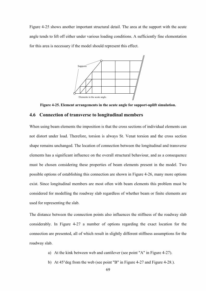
69
Figure 4-25 shows another important structural detail. The area at the support with the acute
angle tends to lift off either under various loading conditions. A sufficiently fine elementation
for this area is necessary if the model should represent this effect.
Elements in the acute angle.
Supports
Figure 4-25. Element arrangements in the acute angle for support-uplift simulation.
4.6 Connection of transverse to longitudinal members
When using beam elements the imposition is that the cross sections of individual elements can
not distort under load. Therefore, torsion is always St. Venat torsion and the cross section
shape remains unchanged. The location of connection between the longitudinal and transverse
elements has a significant influence on the overall structural behaviour, and as a consequence
must be chosen considering these properties of beam elements present in the model. Two
possible options of establishing this connection are shown in Figure 4-26, many more options
exist. Since longitudinal members are most often with beam elements this problem must be
considered for modelling the roadway slab regardless of whether beam or finite elements are
used for representing the slab.
The distance between the connection points also influences the stiffness of the roadway slab
considerably. In Figure 4-27 a number of options regarding the exact location for the
connection are presented, all of which result in slightly different stiffness assumptions for the
roadway slab.
a) At the kink between web and cantilever (see point "A" in Figure 4-27).
b) At 45°deg from the web (see point "B" in Figure 4-27 and Figure 4-28.).

70
c) At the top and in the centre of the web (see point "C" in Figure 4-27).
d) At the shear centre (see point "D" in Figure 4-27).
e) At the centre of gravity (see point "E" in Figure 4-27).
Cross beam ends
at outside face of
main girder cross
section
System line of MG2
in the CG.
System line of MG1
in the CG.
Cross section of MG1 Cross-section of MG2 Outside face of main
girder cross-section.
Cross beam
begin/end System line of MG2
in the CG.
System line of MG1
in the CG.
Cross-section of MG1 Cross-section of MG2 Outside face of main
girder cross-section.
Option “A”
Option “B”
Figure 4-26. Junction of longitudinal and transverse beams.
“A” “B”
“C”
“D”
“E”
B1, B2, B3:
Resulting
structural length
of transverse
beam
B1
B2
B3
Element axis in
the CG.
“D”
Figure 4-27. Possibilities for connecting transverse members to Tee-beam

71
The stiffness of beam or shell elements is also dependent on their geometry. Elements
representing the roadway can be connected directly to the nodes along the longitudinal Tee-
beams. However, in order to model stiffness relationships correctly, rigid links between the
nodes of the longitudinal system and the roadway slab elements are often introduced. The
green triangles in Figure 4-27 indicate “connection points” which are the start- and end-points
of the roadway slab elements.
Moment diagram in cross
beam, connection at “A”
Linear distributed load [kN/m2]
Moment diagram in cross
beam, connection at “B”
45°deg
Moment diagram in cross
beam, connection at “C”
Moment diagram in cross
beam, connection at “D”
Moment diagram in cross
beam, connection at “E”
Figure 4-28. Moment shapes in transverse element.
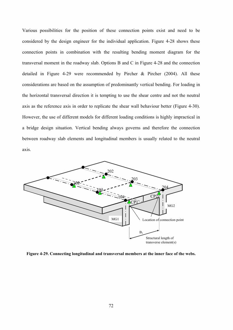
72
Various possibilities for the position of these connection points exist and need to be
considered by the design engineer for the individual application. Figure 4-28 shows these
connection points in combination with the resulting bending moment diagram for the
transversal moment in the roadway slab. Options B and C in Figure 4-28 and the connection
detailed in Figure 4-29 were recommended by Pircher & Pircher (2004). All these
considerations are based on the assumption of predominantly vertical bending. For loading in
the horizontal transversal direction it is tempting to use the shear centre and not the neutral
axis as the reference axis in order to replicate the shear wall behaviour better (Figure 4-30).
However, the use of different models for different loading conditions is highly impractical in
a bridge design situation. Vertical bending always governs and therefore the connection
between roadway slab elements and longitudinal members is usually related to the neutral
axis.
B1
Location of connection point
CP1
CP2
102
103
104
202
203
204
Structural length of
transverse element(s)
MG2
MG1
Figure 4-29. Connecting longitudinal and transversal members at the inner face of the webs.
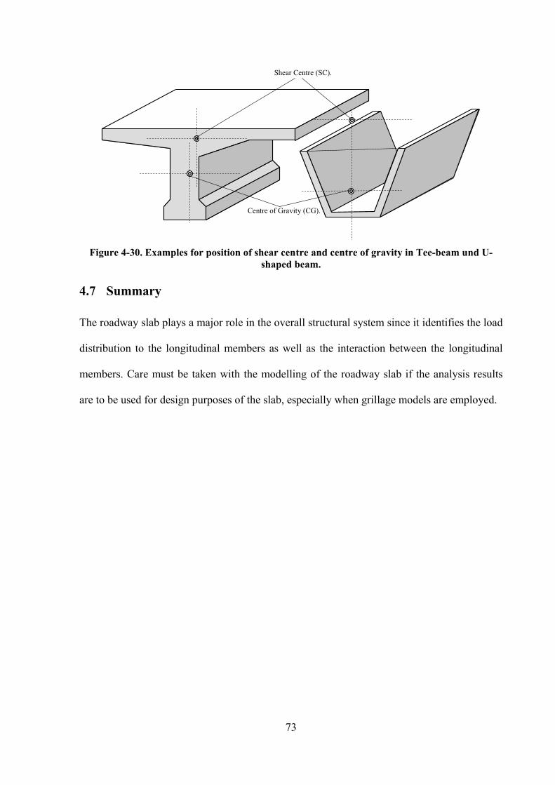
73
Centre of Gravity (CG).
Shear Centre (SC).
Figure 4-30. Examples for position of shear centre and centre of gravity in Tee-beam und U-
shaped beam.
4.7 Summary
The roadway slab plays a major role in the overall structural system since it identifies the load
distribution to the longitudinal members as well as the interaction between the longitudinal
members. Care must be taken with the modelling of the roadway slab if the analysis results
are to be used for design purposes of the slab, especially when grillage models are employed.

74
75
5 Numeric modelling of the main Girders in Tee-beam bridges
This chapter focusses on the function of the longitudinal main girders within the structural
system of a multiple Tee-beam bridge. These main girders transfer the load acting on the
bridge deck to the supports. The design of these members is generally governed by either the
limitation of displacements of the structure or the structural integrity. The limitations of the
displacements vary widely and are defined by the relevant design standard while the structural
integrity requires consideration in both SLS and ULS states.
In most cases these main girders can be considered to act one-dimensionally and in numerical
models they can be represented by beam elements with 6 degrees of freedom. Most of the
static and dynamic effects in case of thick walled concrete cross sections can be covered with
these beam elements. For thin-walled steel cross sections, which are not considered in this
thesis, the warping of the cross-section represents an additional effect which can be
represented by a 7th
degree of freedom. However this often makes the use of 3D finite element
models necessary.
The present chapter is structured into three sub-sections with the following topics. The first
sub-section presents some basic considerations that need to be addressed when representing
the main girders in a structural model. These include the general cross-section of the main
girders; the shear lag effect; the orientation of the principal axes in non-symmetrical cross-
sections; torsion in the main girders; the subdivision of the girder into structural elements; the
connection between girder and supports; continuity of the girders at the supports.
Although the focus of this thesis is on concrete bridges, composite action still occurs as a
result of differences in the erection time regarding different cross-section parts and even the
possible differences of concrete quality between these cross-section parts. In the second sub-
section the modelling of the main girders with respect to this composite situation is detailed

76
looking at the change of cross-section properties in composite beams and the longitudinal
shear in composite interfaces. For such composite situations the general approach is described
together with a few considerations for the SLS and ULS design of the main girder. The
general result presentation specifically for composite girders with an erection procedure in
stages required specific attention.
Finally, in the third sub-section of this chapter the influence of plan view curvatures of bridge
structures will be looked at.
5.1 Basic Considerations
5.1.1 The cross section of the main girder
As discussed in chapter 1 there are many different options for the shape of the Tee-beam
cross-section. As a consequence the structural behaviour and the corresponding modelling for
analysis and design are slightly different for the varying cross-section shapes. Tee-beam
cross-sections can be classified into four general types independently from the number of
webs in the bridge deck (Nilson, 1978) as show in Figure 5-1. In investigating the
considerations for design these four types will be highlighted here.
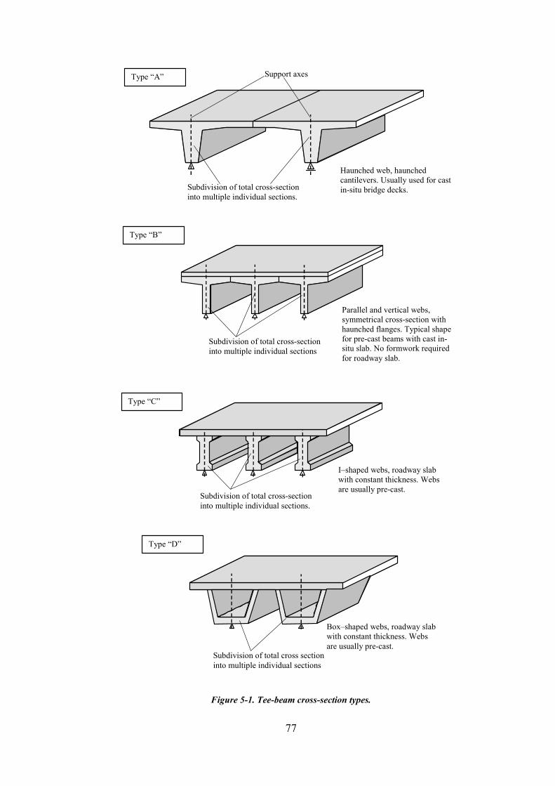
77
Subdivision of total cross-section
into multiple individual sections.
Support axes Type “A”
Haunched web, haunched
cantilevers. Usually used for cast
in-situ bridge decks.
Subdivision of total cross-section
into multiple individual sections
Type “B”
Parallel and vertical webs,
symmetrical cross-section with
haunched flanges. Typical shape
for pre-cast beams with cast in-
situ slab. No formwork required
for roadway slab.
Subdivision of total cross-section
into multiple individual sections.
Type “C”
I–shaped webs, roadway slab
with constant thickness. Webs
are usually pre-cast.
Subdivision of total cross section
into multiple individual sections
Type “D”
Box–shaped webs, roadway slab
with constant thickness. Webs
are usually pre-cast.
Figure 5-1. Tee-beam cross-section types.

78
5.1.2 The shear lag effect
Shear stresses are responsible for activating the individual parts of the cross-section for
resistance against bending. However, the stiffness of the webs is much greater than the
stiffness of the flanges and the roadway slabs with respect to vertical bending and vice-versa
for horizontal bending. Consequently, shear stress concentrations in the flanges around the
connections with the webs can be observed for vertical bending as shown in Figure 5-2.
Variations of shear stresses are commonly approximated by a representative rectangular
distribution. When the error introduced by this approximation becomes to large, and only
certain areas of the cross-section are considered to transmit shear stresses and only these areas
are considered to resist bending action. This effect can be considered on three levels:
1. During the calculation of bending stiffness for the structural analysis for individual
members.
2. During the calculation of fibre stresses based on previously calculated section forces.
3. When doing a non-linear section analysis eg. for the purpose of computing the
moment capacity.
Design codes generally specify the levels at which shear lag needs to be considered. Often,
shear lag is not considered for the analysis but is considered for all sub-sequent operations as
described above.
The extent of the shear lag effect depends on a number of different factors including:
• The cross-section shape of each beam, especially the geometry of the cantilevers for
vertical bending.
• The layout of the individual Tee-beams within the deck, especially the distance
between webs.
• The longitudinal position on the girder in relation to support points.

79
• The particular loading case.
• The normal force present in the beams which is usually governed by the pre-stressing
and post-tensioning of the girders.
• Positive or negative moment.
A number of generalisations and simplifications are commonly made in design codes in order
to standardise the treatment of this effect for design purposes. As a result a procedure that is
commonly given in design codes to compute effective widths of cross-section components is
based on cross-section geometries and span arrangements only. The other listed factors are
accounted for in an approximate fashion. The details of the rules governing the extent of
cross-section reductions depend on the individual design code. Options 1 and 2 in Figure 5-2
illustrate the application of such a design rule for the effective width of the roadway slab of a
multiple Tee-beam bridge.
It should be noted, that the effective width Beff and the influence length Linfl is computed
independently of the individual loading condition, independently of specific material
properties and for linear-elastic material only. All of these assumptions are made in order to
guarantee the validity of result superposition for each individual loading case. The definitions
of Linfl as well as the definitions of effective widths within cross-sections differ in various
international design codes. These differences, however, are minor since the calculation of Linfl
and the effective widths are based on a few general assumptions (Sedlacek & Bild, 1988).
Figure 5-3 illustrates the application of effective widths according to DIN1045 (2004) in a
road bridge in Germany.
In most design codes the consideration of shear lag is not necessary for statically determinate
spans such as simply supported beams. This opens a pandora’s box of technical (and
philosophical) questions for bridge decks made from pre-fabricated Tee-beams with a cast in-
situ deck that is to make a continuous member. In the initial construction stage the individual

80
Tee-beams are placed on their supports and act as simply-supported beams where effective
widths need not be taken into account. Later, when the deck has become structurally effective
and each span can be viewed as a composite system consisting of the pre-cast beams and the
deck, continuity between neighbouring beams is created either by post-tensioning or by the
reinforcement. Strictly speaking, shear lag must be taken into account for this new
configuration creating enormous difficulties by rendering the results of existing loading cases
invalid for superposition, by changing cross-section properties including the position of the
CG etc. In this case it is common practise to compute the effective cross-sections for the final
stage and to also take these cross-sections into account for simply supported configurations.
Figure 5-4 illustrates two cases – where the pre-fabricated beam is affected by effective width
considerations in case (a) and the pre-fabricated beam is not affected in case (b).
Beff
span cross-section
support cross-section
plan view of deck –effective cross-section (option 1) span cross-section
support cross-section
effective width
full effective width
shear stress
distribution
plan view of deck – effective cross-section (option 2)
span cross-section support cross-section
Figure 5-2. Shear lag effect.

81
Figure 5-3. Plan view with effective width reductions near the support cross-sections according to DIN 1045
(2004) taken from a design application for a road bridge in Germany, Europe.
Pre-cast beam with shear
lag effect in flange
Roadway slab only
affected by shear lag.
effective width effective width
(a) (b)
Figure 5-4. Shear lag and pre-cast beams.
Strictly speaking, shear lag effects need to be taken into account for vertical and horizontal
loading alike. For horizontal loading effective width – or should it be called “effective
heights” – considerations would therefore become necessary for the vertical cross-section
components as shown in Figure 5-5. Such considerations would complicate design procedures
significantly, since different models would be necessary for vertical load cases and horizontal
load cases. Determining the superposition results would again be problematic and combined
loading cases would cause some challenging problem. Consider, in this context, the problem
of vertical traffic loading and associated transversal forces in curved alignments. It is
therefore common practise to account for shear lag effects in vertical bending only, and use
the same model for horizontal bending.

82
Beff Beff bridge deck in plan
axes of Tee beams
Uniform horizontal load
support cross section
effective width (height?)
transversal bending
moment in main girders
Figure 5-5. Effective widths for horizontal loading.
5.1.3 The orientation of the principal axes in non-symmetrical cross-sections
Individual cross-sections of multiple Tee-beam systems are not necessarily symmetrical. In
many cases the left-most and the right-most edge beams have an extended outside flange, or
some beams are designed with haunched roadway slabs. Additionally the cross-sections may
be inclined due to a cross-fall resulting in an eccentric CG position as well as in principal axes
that are orientated at an angle to the vertical and horizontal direction. The influences of
inclined principal axes within an unsymmetrical cross section affects the response to both,
vertical and horizontal loads.
When considering beam elements the cross section shape governs many cross-section
properties. Cross-sections with inclined principal axes tend to respond with vertical,
horizontal and rotational displacements when loaded purely vertically (Figure 5-6).
Inclination of the principal axes clearly affects these values and it is up to the engineer to
make a decision on how to consider these effects in a global analysis.
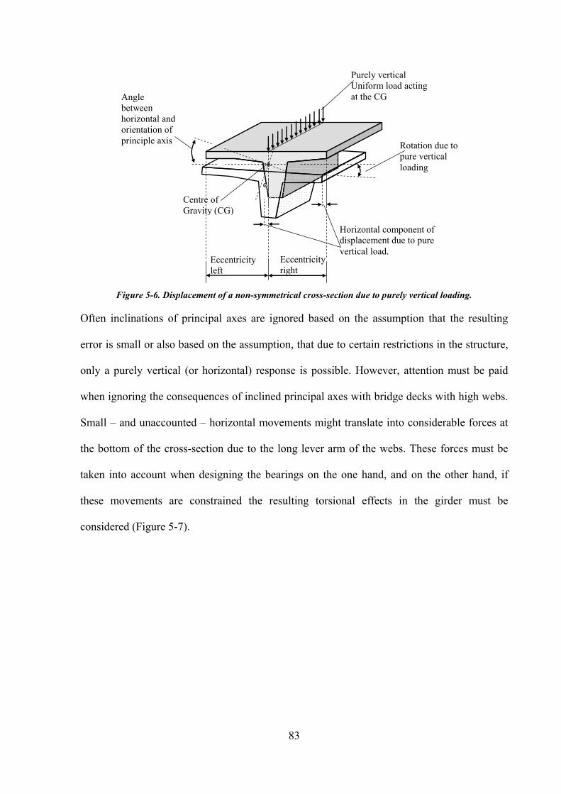
83
Eccentricity
left
Eccentricity
right
Centre of
Gravity (CG)
Angle
between
horizontal and
orientation of
principle axis
Purely vertical
Uniform load acting
at the CG
Rotation due to
pure vertical
loading
Horizontal component of
displacement due to pure
vertical load.
Figure 5-6. Displacement of a non-symmetrical cross-section due to purely vertical loading.
Often inclinations of principal axes are ignored based on the assumption that the resulting
error is small or also based on the assumption, that due to certain restrictions in the structure,
only a purely vertical (or horizontal) response is possible. However, attention must be paid
when ignoring the consequences of inclined principal axes with bridge decks with high webs.
Small – and unaccounted – horizontal movements might translate into considerable forces at
the bottom of the cross-section due to the long lever arm of the webs. These forces must be
taken into account when designing the bearings on the one hand, and on the other hand, if
these movements are constrained the resulting torsional effects in the girder must be
considered (Figure 5-7).
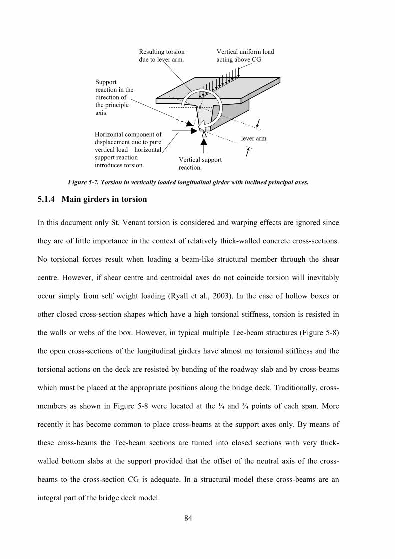
84
Vertical uniform load
acting above CG
Horizontal component of
displacement due to pure
vertical load – horizontal
support reaction
introduces torsion.
lever arm
Support
reaction in the
direction of
the principle
axis.
Resulting torsion
due to lever arm.
Vertical support
reaction.
Figure 5-7. Torsion in vertically loaded longitudinal girder with inclined principal axes.
5.1.4 Main girders in torsion
In this document only St. Venant torsion is considered and warping effects are ignored since
they are of little importance in the context of relatively thick-walled concrete cross-sections.
No torsional forces result when loading a beam-like structural member through the shear
centre. However, if shear centre and centroidal axes do not coincide torsion will inevitably
occur simply from self weight loading (Ryall et al., 2003). In the case of hollow boxes or
other closed cross-section shapes which have a high torsional stiffness, torsion is resisted in
the walls or webs of the box. However, in typical multiple Tee-beam structures (Figure 5-8)
the open cross-sections of the longitudinal girders have almost no torsional stiffness and the
torsional actions on the deck are resisted by bending of the roadway slab and by cross-beams
which must be placed at the appropriate positions along the bridge deck. Traditionally, cross-
members as shown in Figure 5-8 were located at the ¼ and ¾ points of each span. More
recently it has become common to place cross-beams at the support axes only. By means of
these cross-beams the Tee-beam sections are turned into closed sections with very thick-
walled bottom slabs at the support provided that the offset of the neutral axis of the cross-
beams to the cross-section CG is adequate. In a structural model these cross-beams are an
integral part of the bridge deck model.

85
CG of longitudinal girders
Cross-beam at the support axis
plan view
cross-section of
the cross-beam.
vertical
offset of
cross-beam
Figure 5-8. Cross beam arrangement in multiple Tee-beam bridges.
Some guidelines (Hambly, 1991) allow the designer to ignore torsional stiffness in the Tee-
beams outright and require design shear reinforcement for pure shear loading only. However,
by accounting for torsional effects adequately more economical designs may be achieved.
There are two extreme ways of accounting for torsional resistance in this context: The first is
to compute the torsional second moment of inertia IT for each individual longitudinal beam
and use this value for the analysis (Figure 5-9); and secondly, by looking at the deck as a
whole, computing the IT for the full deck cross-section and dividing this value between the
individual longitudinal beams (Figure 5-10). The former option can be considered as a lower
bound and the second option as an upper bound with the physical behaviour of the bridge
somewhere in-between.
When small box-sections are used for the pre-cast girder cross-sections the there is another
aspect to be considered. These sections have a relatively high nominal torsional stiffness.
However, concrete can be assumed to develop cracking due to torsional action and therefore
this nominal stiffness can be greatly reduced. The Australian Bridge Standard AS5100 (2004)
accounts for this effect by prescribing a factor of 0.3 for the torsional stiffness of such beams.

86
Cross-section 1:
Iy, Iz, It
Cross-section 2:
Iy, Iz, It
Cross-section 3:
Iy, Iz, It
Figure 5-9. Computing torsional resistance for each individual Tee-beam.
It cross-section 2 …. Torsion
calculated per cross-section
It cross-section 1 …. Torsion
calculated per cross-section
It total cross-section …. Torsion of
complete cross-section
assigned ½ - ½ to each web.
½ It total cross-section for
cross-section 1
½ It total cross-section for
cross-section 1
Figure 5-10. Distribution of total torsional resistance of bridge deck.
Unterweger (2001) compared different models for assigning torsional stiffness for multiple
Tee-beam bridge decks using the two models referred to as M1 and M2 and shown in Figure
5-11 and Figure 5-12.
The structural system is a grillage consisting of three longitudinal girders and a series of cross
beams connecting Tee-beam 1 with Tee-beam 2 and Tee-beam 3 with Tee-beam 2. The
comparison is done by calculating the two models using both beam elements and finite
elements. The comparison is made on structural systems consisting of two spans with lengths
of 15.0, 17.5, 20.0 and 25.0m as shown in Figure 5-12.
The aim of Unterweger’s comparison is to demonstrate the effect the influence of the
torsional stiffness on the quality of the bending results in grillage structures.

87
The model M1:
In model M1 the torsional inertia It for the total cross-section (Area of Tee-beam1 +
Tee-beam2 + Tee-beam3) is assigned to the Tee-beam 2 only. The edge Tee-beams 1
and 3 have no individual It, but are connected with the Tee-beam 2 via element
representing the roadway slab.
The model M2:
In model M2 the torsional inertia It for the total cross-section (Area of Tee-beam1 +
Tee-beam2 + Tee-beam3) is assigned proportionally: It/2 for Tee-beam 1 and It/2 for
Tee-beam 3. The It of Tee-beam 2 is set to zero.
For both model M1 and M2 the impact of the shear lag and the horizontal behaviour is
neglected. All the other properties (areas Ax, Ay and Az and inertias Iy and Iz) are assigned to
Tee-beam 1,2 and 3 as they result from the cross-section geometry of the individual Tee-
beams.
Loading case 1: 5,0 kNm2 Loading case 2: 5,0 kNm
2
Tee-beam 1 Tee-beam 2 Tee-beam 3
Figure 5-11. Example: structural system, loading cases 1, 2 on bridge deck.
Two loading cases are considered, one symmetrical and one non-symmetrical loading, both
with a uniform load of 5.0kN/m2.

88
Span lengths:
15.0m 17.5m,
20.0m, 25.0m
Span lengths:
15.0m 17.5m,
20.0m, 25.0m
Figure 5-12. Example: Span arrangement and structural system.
The results for vertical bending (My) of M1 and M2:
Loading case 1, symmetrical load:
The results for both models M1 and M2 are identical for all three Tee-beams.
Loading case 2, non-symmetrical load:
The differences between the models M1 and M2 appear when looking at the results of
this non-symmetrical loading case. The bending of Tee-beam1 causes bending of the
cross beam linking Tee-beam1 with Tee-beam2. This bending of the cross beam
introduces torsion into Tee-beam2, this torsion causes bending of the cross beam
between Tee-beam2 and Tee-beam3 which introduces torsion to Tee-beam3.
Unterweger results show the difference between the models M1 and M2, when looking at the
bending of the Tee-beams the difference is 14% for the longest spans of 25.0m each and 11%
for the shortest span length of 15.0m.
As an additional step Unterweger modelled the same deck with finite elements and calculated
the same two loading cases in order to compare the grillage results for vertical bending of M1
and M2 to a FE calculation.
This comparison shows that the results of model M2 is closer to the results of the Finite
Element Model. The differences are between 3 and 7% depending on the span lengths
whereas the differences between the model M1 and the FE model, again depending on the
span lengths, are between 5 to 12%.

89
Unterwegers example shows that the assignment of the torsional inertia does have a major
impact on the quality of the grillage model. Unterweger also concludes that the torsional
inertia It of the edge beams has the biggest influence on the structural behaviour. The It of the
Tee-beams has a smaller impact on the overall structural behaviour.
5.1.5 The subdivision of the girder into structural elements
Each longitudinal girder must be subdivided into a number of individual longitudinal
elements in a numerical model in order to give results of appropriate accuracy. As a general
rule it should be kept in mind that primary analysis results are always generated in the nodes
of numerical models. Post-processing allows the interpolation of results anywhere in-between
nodes along these girders, but post-processing usually reduces accuracy and therefore some
thoughts should be expended on the number of sub-division and on the locations where results
are needed for design purposes. As a general rule of thumb it is recommended that a minimum
of ten elements per span and element series should be defined to each girder.
Results within the Tee-cross-sections are also often of interest, for example the designer may
want to know the shear stresses between the webs and the flanges or the bending stresses at
the joint between web and flanges (Figure 5-13). Considerations of this kind may in some
instances lead to a cross-section sub-division as shown in Figure 5-14 resulting in a very
detailed set of results for the stress distribution within the Tee-cross-section. However, for
each cross-section sub-division, a separate series of elements must be set up longitudinally
and the corresponding lateral configurations must also be established, thus quickly leading to
enormous model sizes. Furthermore, with a detailed model such as outlined in Figure 5-14
redistribution of pre-stressing forces to the full Tee-beam cross-section can only be achieved
with modelling tools that have advanced procedures (Figure 5-15). As a compromise it is
common practise that in many bridge design offices general cross-section models are
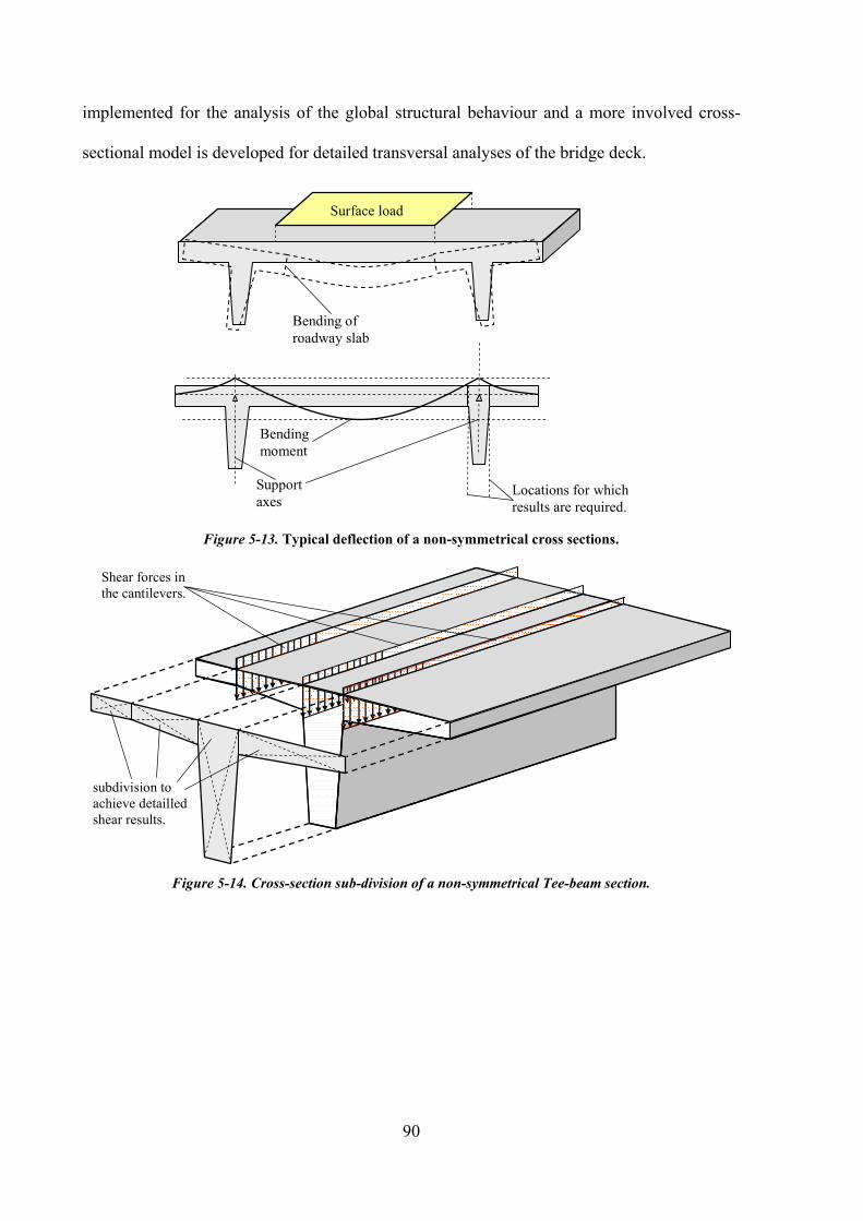
90
implemented for the analysis of the global structural behaviour and a more involved cross-
sectional model is developed for detailed transversal analyses of the bridge deck.
Bending of
roadway slab
Support
axes
Bending
moment
Surface load
Locations for which
results are required.
Figure 5-13. Typical deflection of a non-symmetrical cross sections.
Shear forces in
the cantilevers.
subdivision to
achieve detailled
shear results.
Figure 5-14. Cross-section sub-division of a non-symmetrical Tee-beam section.

91
Single cross
section.
stresses in the
top fibre due to
pre-stressing
Stresses in the
top fibre due to
pre-stressing
split cross-
section
Pre-stressing
tendon in the
web
Figure 5-15 Stresses in the top fibre due pre-stressing in the web.
5.1.6 Connection between girder and supports
At the abutments and the piers each web of the Tee–beams in the bridge deck are supported
resulting in a relatively high number of bearings particularly in multiple Tee-beam structures.
If cross-beams are placed at the piers the number of bearings can be reduced in these support
points. For cast in-situ Tee–beam structures rigid connections between piers and deck are
sometimes implemented which is normally not an option for structures with pre-cast girders.
Pre-cast beams are almost always put in place as simply supported beams supported at the
piers as shown in Stage 1 in Figure 5-16. The deck is then cast onto these beams and the gaps
between girders above the piers in the longitudinal direction are closed. Depending on how
this closure detail is constructed partial or full continuity can be achieved (Stage 2 in Figure
5-16). In cases where full continuity is the goal, the original supports are oftentimes replaced
by final bearings as shown in Stage 3 in Figure 5-16. This procedure represents a significant
change in structural system which must be carefully accounted for in the structural analysis.

92
Stage 1: pre-cast simply supported
beams.
Stage 2: pre-cast beams with wet
concrete weight.
Stage 3: remove temporary supports,
continuity activated.
Figure 5-16. Construction sequence with temporary supports.
5.1.7 Continuity
Figure 5-16 shows in stage 3 a continuous beam. Any load applied on the structure at this
stage gives a negative moment over the pier. The negative moment reduces the positive
moment in the spans and this might be an important design consideration. In case the
continuity is wanted the negative moment must be covered by appropriate reinforcement
covering the tensile stresses at the top fibre. The concrete will still be cracked, but a certain
amount of the tensile stresses are compensated by the reinforcement bars.
Full continuity can be achieved by installing an additional tendon at the pier covering the
negative moment which has not existed for the stages 1 and 2 in Figure 5-16. Full continuity
means that the girder is under all circumstances under compression at both the top and the
bottom fibre stresses.
The PT creating full continuity can either be a straight or curved layout in elevation as shown
in Figure 5-17. A straight PT layout is easier to install, whereas for a curved PT layout one
must foresee the anchorages in the pre-cast beam already when casting the girder in the
casting yard.
Partial continuity can be achieved in two ways. In one case the additional PT does not create
full compression at both the top and bottom fibre for the final stage. Getting tensile stresses at
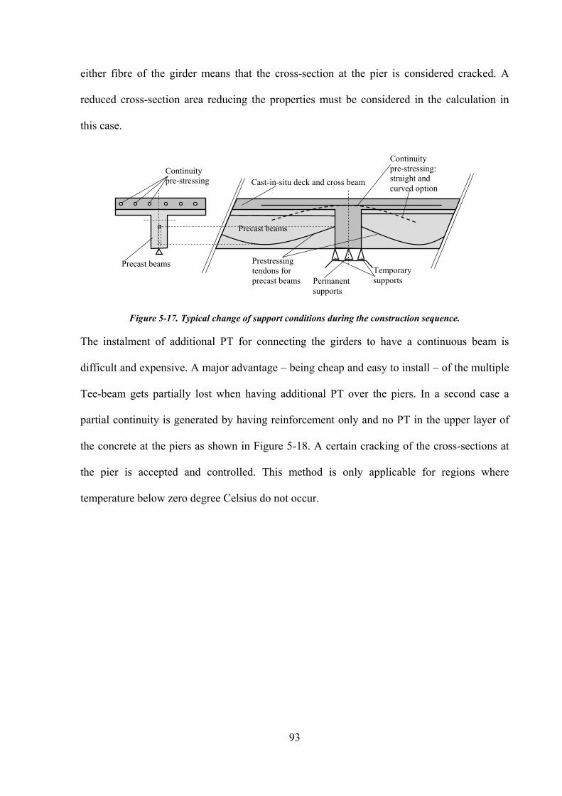
93
either fibre of the girder means that the cross-section at the pier is considered cracked. A
reduced cross-section area reducing the properties must be considered in the calculation in
this case.
Precast beams
Precast beams Prestressing
tendons for
precast beams
Temporary
supports Permanent
supports
Cast-in-situ deck and cross beam
Continuity
pre-stressing:
straight and
curved option
Continuity
pre-stressing
Figure 5-17. Typical change of support conditions during the construction sequence.
The instalment of additional PT for connecting the girders to have a continuous beam is
difficult and expensive. A major advantage – being cheap and easy to install – of the multiple
Tee-beam gets partially lost when having additional PT over the piers. In a second case a
partial continuity is generated by having reinforcement only and no PT in the upper layer of
the concrete at the piers as shown in Figure 5-18. A certain cracking of the cross-sections at
the pier is accepted and controlled. This method is only applicable for regions where
temperature below zero degree Celsius do not occur.

94
Precast beams
Precast beams Prestressing
tendons for
precast beams
Temporary
supports Permanent
supports
Cast-in-situ deck and cross beam Continuity
reinforcement:
Reinforcement
layers
My – simple supported.
My – full continuity.
My – partial continuity.
Figure 5-18. Partial continuity using reinforcement at the pier.
The need to control the situation at the pier has led to several practical solutions. In some
countries like Spain and Australia the so called “link slab” is today common practice for pre-
cast multiple Tee-beam structures. The principle is to install a layer between the pre-cast part
and the cast in-situ concrete. For the length of the layer no force is transferred between the
two parts. For the analysis the cracked cross-section at the junction between the pre-cast
beams can be simulated as spring element representing the same axial stiffness as the
reinforcement passing through the cast in-situ slab over the pier. Together with the geometric
eccentricity of the spring element relative to the CG of the composite cross-section a certain
reduced negative moment at the pier is developed due to additional load on the final system.
Figure 5-19 shows the principle of this method, the resulting moment is similar to the My –
partial continuity as shown in Figure 5-18.

95
Temporary
support
Final
support
Layer – no
composite connection
Shear studs – composite
connection
Spring
element
Length of layer
Eccentricity
of spring
element
Figure 5-19. Link slab system for partial continuity.
5.2 Composite Action
5.2.1 Change of cross-section properties in composite beams
A composite cross-section in the following paragraphs is defined as a cross-section consisting
of different cross-section parts. These individual cross-section parts may have different
material properties and/or may be constructed at different time during the erection sequence.
In the structural model these individual parts can be represented as either finite elements or
beam elements or a combination of both. The difference in construction time, the difference in
material properties create numerous interesting effects which need to be accounted for in a
structural analysis. In bridge structures the connection between cross-section part is
commonly established in a way to guarantee “full composite action” – meaning that
longitudinally no elastic or plastic slip between cross-section parts is possible.
Differences in stiffness of the materials acting compositely affect the distribution of internal
forces in the structure. Stiffer cross-section parts attract proportionally higher internal forces.
It is common practise to transform the individual material properties present in a composite
cross-section into one reference material and use the equation outlined in (5.1) to compute a
modular ratio for each cross-section part. For composite cross-sections consisting of parts
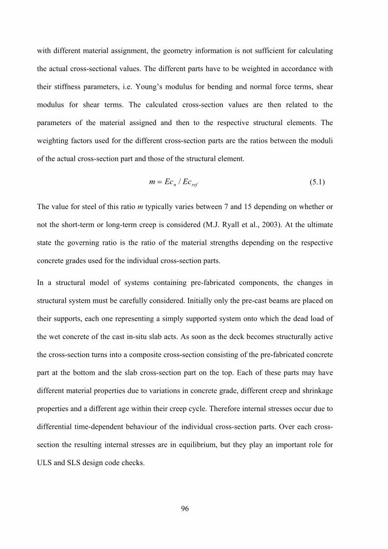
96
with different material assignment, the geometry information is not sufficient for calculating
the actual cross-sectional values. The different parts have to be weighted in accordance with
their stiffness parameters, i.e. Young’s modulus for bending and normal force terms, shear
modulus for shear terms. The calculated cross-section values are then related to the
parameters of the material assigned and then to the respective structural elements. The
weighting factors used for the different cross-section parts are the ratios between the moduli
of the actual cross-section part and those of the structural element.
refn EcEcm /= (5.1)
The value for steel of this ratio m typically varies between 7 and 15 depending on whether or
not the short-term or long-term creep is considered (M.J. Ryall et al., 2003). At the ultimate
state the governing ratio is the ratio of the material strengths depending on the respective
concrete grades used for the individual cross-section parts.
In a structural model of systems containing pre-fabricated components, the changes in
structural system must be carefully considered. Initially only the pre-cast beams are placed on
their supports, each one representing a simply supported system onto which the dead load of
the wet concrete of the cast in-situ slab acts. As soon as the deck becomes structurally active
the cross-section turns into a composite cross-section consisting of the pre-fabricated concrete
part at the bottom and the slab cross-section part on the top. Each of these parts may have
different material properties due to variations in concrete grade, different creep and shrinkage
properties and a different age within their creep cycle. Therefore internal stresses occur due to
differential time-dependent behaviour of the individual cross-section parts. Over each cross-
section the resulting internal stresses are in equilibrium, but they play an important role for
ULS and SLS design code checks.

97
The activation of composite action also means that the position of CG shifts (Figure 5-20) and
internal forces from one configuration must be transformed into the other configurations using
correct procedures. This transformation is especially complicated for shear and torsional
stress resultants. This means that superposition of internal forces is not simply a matter of
adding results, now all results must be related to a reference state of the cross-section.
However this problem can also be overcome by adding together stresses or strains instead of
forces (Figure 5-21).
eccentricities
of upper and
lower part.
Position of CG … composite
Position of CG … part 1
Position of CG … part 2
Figure 5-20. Change of CG in composite cross-sections.
Forces at the cross section:
My….bending moment
Vy… shear force
Nx… normal force
Stresses top
Stresses bottom
…. Stage 1
Stresses top
Stresses bottom
…. Stage 2
Total stresses:
stage1+stage2
Figure 5-21. Development of stresses and internal forces in composite cross-section.

98
5.2.2 Longitudinal shear in composite interfaces
Cross-section parts must be connected appropriately in the longitudinal direction in order to
achieve the required full composite behaviour (Figure 5-24) with all cross-section parts acting
together as one composite cross-section. Due to specific construction and loading sequences
complicated stress-patterns are often induced into composite cross-sections. Shear stresses in
the interfaces between cross-section parts must be computed accurately in order to be able to
design the appropriate shear connector (Figure 5-22).
Stresses top
Stresses bottom
…. Stage 1
Stresses top
Stresses bottom
…. Stage 2
Total stresses:
stage1+stage2
Stress difference:
longitudinal force
to be taken in the
interface.
Longitudinal
shear force.
Shear
reinforcement
Figure 5-22. Stress distribution in cross-section parts and stress difference in the interface.
Shear connectors are devices for ensuring the force transfer in the interface. In practice the
shear connectors are found in two basic forms (Ryall et all, 2003).
Flexible connectors such as headed studs behave in a ductile manner allowing significant
movement or slip at the ultimate limit state. At the serviceability state the loads on the
connectors should be limited to approximately half the connector’s static strength to limit slip.
For concrete-concrete composite situation the failure is caused by crushing of the concrete.
At the serviceability limit state there should be sufficient shear connectors to prevent slip
between cross-section parts. According to Ryall et all (2003) the minimum number of
connectors required per unit length is:
un PqN 55.0/0 = (5.2)
And at the ultimate limit state the minimum number of connectors required is:

99
un PqN 8.0/)(0 χ= (5.3)
For determining the required shear connector configuration, most design codes require the
calculation of shear forces in the interface for the both ULS and the SLS combination.
The following procedure is generally applied to determine the shear at the interface (Ryall et
all, 2003). A horizontal section with the width ”b“ is placed in the cross-section at the level of
the interface. The static moment ”Sz“ of the cross-section part cut away is calculated. The
shear stress xyτ is then calculated using the formula bJ
SQ
z
zy
xy ∗∗=τ . (5.4)
This procedure is only valid in case the connection face is parallel to the neutral axis and the
cross section geometry is constant. Computer programs commonly use a more general
approach for the computation of the shear stresses in the interfaces. The shear stresses in the
connection face must correspond to the change of the normal force (dN/dx) transmitted in
each part that is separated by the considered interface. The normal force difference between
the start and the end of a composite element is proportional to the shear force transmitted by
the reinforcement over the element length. This value can then be used to design the shear
connectors within this element. However, there is an additional complication arising from this
algorithm. Design load combinations usually give extreme design forces with co-existing
force vectors for each result point. Since results from two different points are used in the
above-described algorithm it cannot be guaranteed that a set of results in the start node co-
exists with the set of results in the end node. It therefore necessary to check the resulting
difference in normal force for each individual loading case and then accumulate these values
separately (Figure 5-23), thus guaranteeing consistent results for the shear interface in the
design combinations. Figure 5-24 illustrates this procedure for a simple example consisting of
a simply supported composite Tee-beam.

100
In some design codes (e.g. DIN1045, 2004) the plastic moment of a composite cross-section
needs to be computed and the related total compression force in the concrete and the total
tension force in the reinforcement in the cracked areas must be determined. Shear connectors
must be able to transfer these forces.
NXmin and NXmax
Load combination 1
for element end.
Shear
reinforcement
NXmin and NXmax
Load combination 2
for element end.
Load combination
for combination
element
104 105
Figure 5-23. Accumulation of shear forces in the interface.

101
Position of
CG for
composite
cross section
Differential
longitudinal
displacement.
No
longitudinal
shear force in
the interface
Longitudinal shear force in the
interface, no differential longitudinal
displacement in the interface
No differential
longitudinal
displacement.
Longitudinal
shear force in the
interface
Longitudinal shear force for the
combination elements in the interface.
Figure 5-24. Shear force in the interface.
5.3 Curvature in plan
Constructing curved bridges with pre-cast beams usually involves approximating the
alignment with a polygonal alignment that can be built with straight pre-fabricated beams.
The edge beams are sometimes constructed with curved outside flanges to achieve exact deck
geometry. A similar technique is sometimes applied when road widening must be achieved. In
this case the flanges of all beams within a span are sometimes widened over their length
resulting in different deck widths at span begin and end. Consequently additional care in

102
design must be taken and the implications of these widenings on all the above mentioned
behaviour must be considered. Due to the geometry the permanent load along such straight
pre-cast beam is consequently variable in intensity and eccentricity as shown in Figure 5-25.
The load definition for curved pre-cast beams is therefore the most difficult part.
Support axes
Webs of straight precast beams
Curvature of bridge deck
Variable offset
Figure 5-25. Approximating a curved bridge with pre-fabricated straight beams.
5.3.1 Transportation and stability of pre-cast pre-stressed girders.
The transport is an issue that is generally not addressed by international design codes.
However it represents an additional construction stage which might be a structurally critical
one. In general, the lengths of pre-cast concrete girders are limited by the constraints of
transportation and handling systems A trend towards longer spans with single-length
members has resulted in need for deeper I- and T-beam sections. The centre of gravity of
these members is high above the roadway making their transportation difficult. The presence
of tensile stresses in the top flanges requires that these beams are laterally supported near their
ends during hauling to minimize lateral instability during transit.
The lateral stability problem is also encountered during handling of I- and T-beams with large
depth as such as they may be tipped sideways, forcing the web out of the vertical plane and
thus initiating their buckling. The lateral buckling problem of pre-stressed concrete beams is
of different type than the one of steel members with thin-walled open cross-sections. Pre-
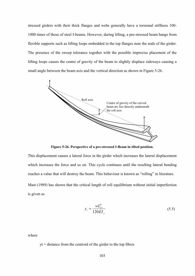
103
stressed girders with their thick flanges and webs generally have a torsional stiffness 100-
1000 times of those of steel I-beams. However, during lifting, a pre-stressed beam hangs from
flexible supports such as lifting loops embedded in the top flanges near the ends of the girder.
The presence of the sweep tolerance together with the possible imprecise placement of the
lifting loops causes the centre of gravity of the beam to slightly displace sideways causing a
small angle between the beam axis and the vertical direction as shown in Figure 5-26.
Roll axis Centre of gravity of the curved
beam arc lies directly underneath
the roll axis
Figure 5-26. Perspective of a pre-stressed I-Beam in tilted position.
This displacement causes a lateral force in the girder which increases the lateral displacement
which increases the force and so on. This cycle continues until the resulting lateral bending
reaches a value that will destroy the beam. This behaviour is known as “rolling” in literature.
Mast (1989) has shown that the critical length of roll equilibrium without initial imperfection
is given as
y
crt
EI
wLy
120
4= (5.5)
where
yt = distance from the centroid of the girder to the top fibres

104
W = weight of the beam per length unit
E = elastic modulus of concrete
Iy = moment of inertia about the weak axis.
A mathematical treatment of the behaviour of long precast pre-stressed concrete beams during
transportation and handling as well as ways of increasing their stability during these
operations has been presented by Mast (1989).

105
6 Pre-cast Tee-beams worldwide
6.1 Introduction
As outline in Chapter 1 multiple Tee-beams are common and represent worldwide about 40%
of all today’s bridges in the urban areas Slatter (1980). In this chapter an overview of the
typical cross-sections and erection methods that are in use for pre-cast multiple Tee-beam
structures is presented in an endeavour give an international overview and to develop
categories and libraries of typical bridge parameters.
A number of authorities worldwide have set up guidelines for the design and construction of
multiple Tee-beam bridges. Furthermore, a number of guidelines or design facilities have
been made available for the engineers during the last 30 years based on typical cross-section,
typical arrangements or typical span. There are guidelines and recipes for design, there are
typical drawings and standard details available. In the following review typical cross-sections,
span arrangements and structural details for today’s most common international design codes
are presented. Certain local modifications are considered as well and in some countries, where
there are guidelines this is also indicated.
6.2 Great Britain
Pre-tensioned pre-stressed concrete bridge beams have been used in the UK as a major form
of bridge construction for the past 50 years. In the 1960’s the pre-stressed beam type was
accepted as national standard. These beams are provided by a number of suppliers, with three
basic forms of pre-stressed beam being used. Recently trends towards sections that allow
inspection of all surfaces, increase cover requirements and integral construction has led to the
introduction of the Y-beam range, which may be used for both solid slab and beam-slab
construction.

106
Recommendations for cross-sections, slab form the span lengths for which are reasonable and
economical are shown in Figure 6-1 along with resulting girder depth. .
Figure 6-1. Summary of typical cross-sections by Howard Taylor, Tarmac (1998).
From Figure 6-1 a number of deck types are presented and typical solid slab utilising the TY
beams is presented in Figure 6-2. In this case the pre-cast members are enclosed with in the
slab system.
Figure 6-2. The Solid slab deck using TY-beams.
In Figure 6-3, the SY beams are utilised, in this case the slab is formed on top of the beams
forming a beam slab system. With this system it is possible to inspect all surfaces of the
beams.

107
Figure 6-3. The Solid slab deck using SY-beams
The third type of slab referred to is the beam and slab/voided, these deck are typically used
for the longer spans where minimising the concrete is advantageous. A typical voided cross-
section is shown in Figure 6-4 where the U beam is utilised (Bangash, 1990).
Figure 6-4. The Solid slab deck using U-beams
The in-situ slab in has a special form for the edge where the kerbs are constructed together
with the slab and not within a separate step using other pre-cast elements. Figure 6-5 shows a
beam and slab/voided system utilising the M-Beam, in this case a variation of the slab edge is
shown.
Figure 6-5. Cross section and section properties of pre-cast pre-stressed concrete beams used in
England. Edge beam variant and standard section, Narendra Taly (1998).
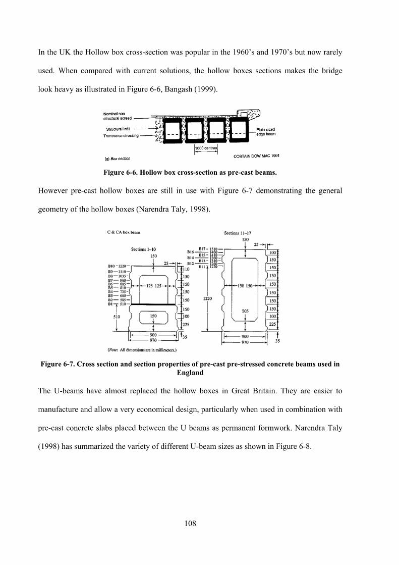
108
In the UK the Hollow box cross-section was popular in the 1960’s and 1970’s but now rarely
used. When compared with current solutions, the hollow boxes sections makes the bridge
look heavy as illustrated in Figure 6-6, Bangash (1999).
Figure 6-6. Hollow box cross-section as pre-cast beams.
However pre-cast hollow boxes are still in use with Figure 6-7 demonstrating the general
geometry of the hollow boxes (Narendra Taly, 1998).
Figure 6-7. Cross section and section properties of pre-cast pre-stressed concrete beams used in
England
The U-beams have almost replaced the hollow boxes in Great Britain. They are easier to
manufacture and allow a very economical design, particularly when used in combination with
pre-cast concrete slabs placed between the U beams as permanent formwork. Narendra Taly
(1998) has summarized the variety of different U-beam sizes as shown in Figure 6-8.

109
Figure 6-8. U-beam: Cross-sections of pre-cast pre-stressed concrete beams used in England.
For shorter spans the typical I- and Y-beam allows for easy and quick erection. Again Taly
(1998) has summarized the variety of different I- and Y-beam sizes as shown in Figure 6-9.
Figure 6-9. I-beam: Cross section shapes and details for reinforcement and tendons of pre-cast
pre-stressed concrete beams used in England.
Taly (1998) gives an overview of typical dimensions and structural details for both
reinforcement and pre-stressing deck systems as shown in Figure 6-10. The chart gives a

110
guide to the span range of seven beam types from a particular manufacturer, also presented
are typical Applications and the advantages of the beam types.
Figure 6-10. Overview of typical pre-cast cross-sections and typical applications for England.
The Pre-stressed Concrete Association publication covering the handling of bridge beams on
site provides guidance to planning supervisors, design engineers and contractors on this phase
of the procurement and construction. The British Standards does not propose or predict a
specific erection method.
6.3 United States
The United States might be considered as being the country with the highest percentage of
pre-cast pre-stressed Tee-beam bridges. The construction method has been made perfect and
the manufacturers have developed specific know how during the 1960’s and 1970’s. This
specialisation is illustrated by the fact that pre-cast Tee-beams are also known as “AASHTO-
girders” in many countries in the world.

111
As a result of the high level of use the authorities have set up specific and detailed guidelines
of how the cross-sections have to look like, what span arrangement one should consider and
what the preferred erection methods are. The following while only a brief extract illustrates
how detailed the guidelines from the Departments of Transportation are. Taly (1998) has also
classified the typical cross-sections for the United States as shown in Figure 6-11.
Figure 6-11. Overview of typical pre-cast cross-sections and typical applications in the United
States.
The U-shaped cross-section is not presented in Figure 6-11 but is used extensively through
out the US. Campbell and Bassi (1994) have classified this shape as shown in Figure 6-12.

112
Figure 6-12. Typical transverse section through a pre-stressed trapezoidal girder bridge.
As a sample the requirements for the California, Florida, Minnesota and Washington
regulative bodies are summarized, looking at the cross-sections, the span arrangement and the
structural details. These details are a summary of information found on various internet sites
for the respective Departments of Transportation.
6.3.1 US – California (www.dot.ca.gov)
In California the Ministry of Transport (Caltrans) released a guideline called “Bridge
Specifications” with the latest release in 2004. The guideline has been published on the
internet only and contains detailed information about all typical cross-sections, construction
methods and design advices.
Typical cross-sections and section properties are shown in Figure 6-13 and Figure 6-14 for the
I beams and “Bulb-Tee” respectively.
Figure 6-13. I-Girder from Caltrans – Bridge Design Specifications February 2004.

113
Figure 6-14. “Bulb-Tee Girder” from Caltrans – Bridge Design Specifications February 2004.
The typical U-beams referred to as the “Bathtub girders” are shown in Figure 6-15.
Figure 6-15. “Bathtub Girder” from Caltrans – Bridge Design Specifications February 2004.
A special type of pre-cast beams has been developed in California and is shown in Figure
6-16. These Double Tee-beams allow a very quick bridge deck erection and serve as
formwork for the cast in-situ concrete as well. The width of these Double Tee-beams is up to
1.20m and the webs are relatively slender and high which allows only limited pre-stressing.
Consequently the application is limited for short spans of max. 20.0m.

114
Figure 6-16. Double Tee-beam from Caltrans – Bridge Design Specifications February 2004.
Combining the practicality of I-beams and utilising the wide top flange as formwork
Anderson (1972) developed new type called the “Bulb T-beams” as shown in Figure 6-17.
The wider bottom flange gives space for pre-tensioning and the wide top flange allows to
place the girders next to each other allowing a quick and easy casting of the deck. As the
thickness of the webs is minimised the sections are sensitive to buckling. This makes local
stabilisations necessary resulting in the need of installing pre-cast transverse bracing
connection the web as shown in Figure 6-17. According to Anderson (1972) these pre-cast
bracings are installed in mid-span for spans greater than 18.0m.
Figure 6-17. Pre-stressed decked bulb T-beams, Anderson, 1972.
The guidelines from Caltrans contain complete design examples as well as containing
suggestions for span configurations and choice of appropriate cross-section and structural

115
details. Typical details are shown in Figure 6-18 show a bridge in plan and elevation together,
the beam tendon geometry and guidelines to cover the situation for skew supports is also
shown.
Figure 6-18. Extract of a Caltrans – Bridge Design Specifications design example with hollow
box cross-section.
The same example is explained for several different cross-sections and Figure 6-19 shows the
suggestions for the use of pre-cast hollow box cross-sections. Although like the UK the
sections are rarely used and look heavy with the design not being economical.
Girder depth
4
5 6
7
8
Total R4 content
21
23 25
29
31
Const. joint
Stirrups type R4
Figure 6-19. Extract of a Caltrans – Bridge Design Specifications design example with hollow
box cross-section.

116
Path of centre of gravity of prestressing Steel to approximate a parabola.
Figure 6-20. Caltrans – Bridge Design Specifications February 2004 using “Bulb T-beams”.
Figure 6-20 shows the third option for the mentioned Caltrans design manual using “Bulb T-
beams”. The example shows the straight geometry for the pre-tensioning strands and the
curved position of the duct allowing for later post-tensioning.
Figure 6-21. Support detail for I-beam from Caltrans – Bridge Design Specifications
February 2004.
The Caltrans Design manual goes to the extent of giving details for the support of beams as
shown Figure 6-21. This detail shows that the web thickness of the cross-section is being
increased at the ends in order to give place for the shear reinforcement and the anchorages of
the post-tensioning tendons.
For spans longer than 18.0 metres Caltrans recommends the installation of pre-cast or cast in-
situ diaphragms in mid-spans to provide stability for the beams.
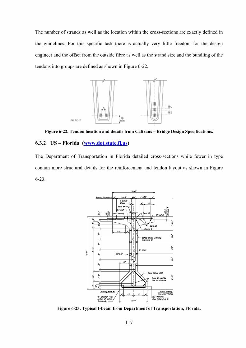
117
The number of strands as well as the location within the cross-sections are exactly defined in
the guidelines. For this specific task there is actually very little freedom for the design
engineer and the offset from the outside fibre as well as the strand size and the bundling of the
tendons into groups are defined as shown in Figure 6-22.
Figure 6-22. Tendon location and details from Caltrans – Bridge Design Specifications.
6.3.2 US – Florida (www.dot.state.fl.us)
The Department of Transportation in Florida detailed cross-sections while fewer in type
contain more structural details for the reinforcement and tendon layout as shown in Figure
6-23.
Figure 6-23. Typical I-beam from Department of Transportation, Florida.

118
The typical U-section is shown in Figure 6-24, as detailed the pre-cast section already
contains reinforcement for the connection to the cast in-situ slab. The position dimensions and
number of strands for the pre-tensioning are predefined as shown in Figure 6-25. The number
and dimension of strands dependent on the span length and bridge type for which the girders
are used.
Figure 6-24. Typical U-beam from Department of Transportation, Florida.
Figure 6-25. Tendons in typical U-beam from Department of Transportation, Florida.
To minimise deflections due to pre-stressing and to ensure sufficient strength at the mid-span
of the section unbounded tendons are utilised as shown in Figure 6-25.
The Florida Department of Transportation has also proposed a new type of cross-section for
small to medium sized spans. This section is referred to as the Half I-beam section and is
shown in Figure 6-26, similar to the U-section presented in Figure 6-25 several tendons are
also unbonded.
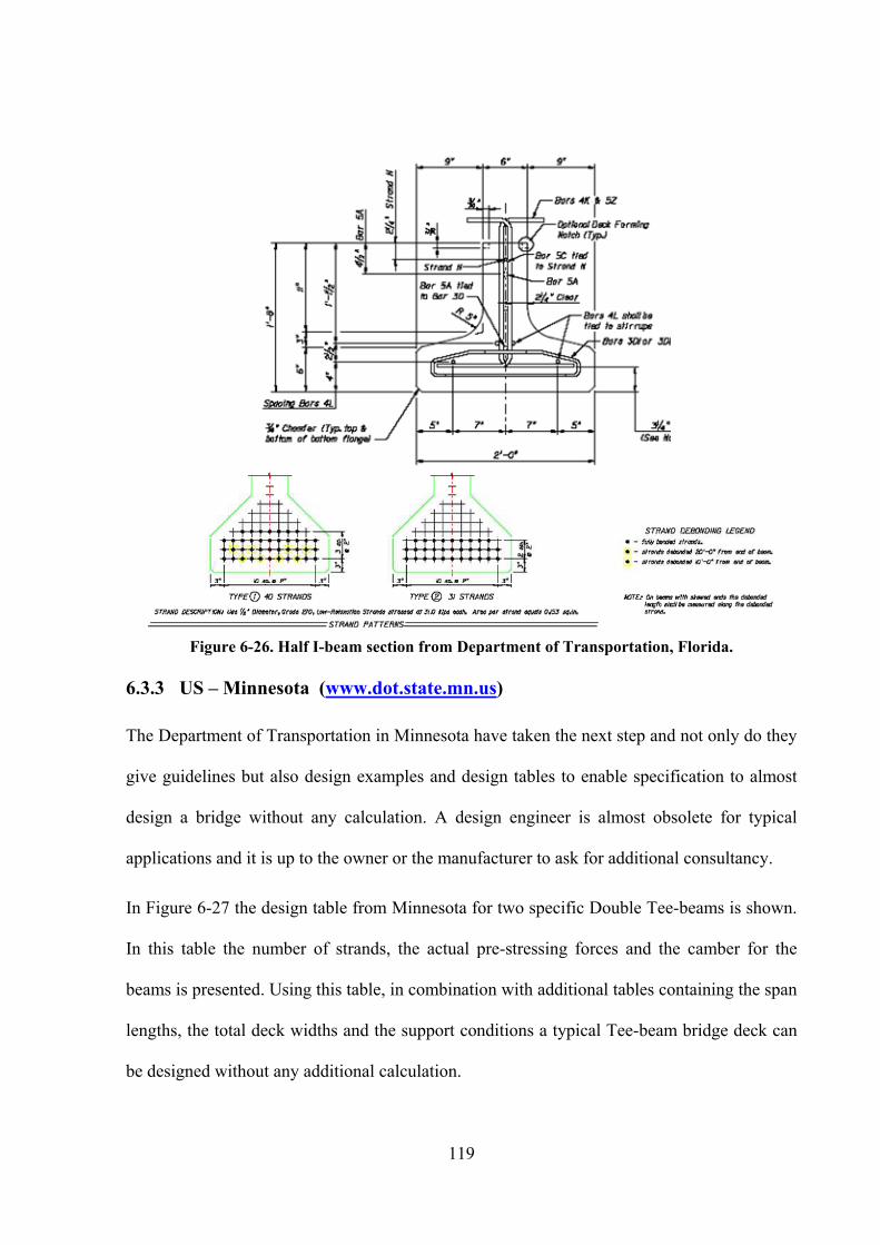
119
Figure 6-26. Half I-beam section from Department of Transportation, Florida.
6.3.3 US – Minnesota (www.dot.state.mn.us)
The Department of Transportation in Minnesota have taken the next step and not only do they
give guidelines but also design examples and design tables to enable specification to almost
design a bridge without any calculation. A design engineer is almost obsolete for typical
applications and it is up to the owner or the manufacturer to ask for additional consultancy.
In Figure 6-27 the design table from Minnesota for two specific Double Tee-beams is shown.
In this table the number of strands, the actual pre-stressing forces and the camber for the
beams is presented. Using this table, in combination with additional tables containing the span
lengths, the total deck widths and the support conditions a typical Tee-beam bridge deck can
be designed without any additional calculation.

120
Figure 6-27. Design chart for Double Tee-beams from Department of Transportation,
Minnesota.
Figure 6-28. Tendon arrangement for I-beams from Department of Transportation, Minnesota.
The pre-stressing and reinforcement details for I-beams are shown in Figure 6-28. The cross-
sections for the mid-span as well as for the end of the girder indicate that two different types
of pre-tensioning are in use. The straight tendons in the bottom flange of the I-beam and the
draped tendons being in the top flange at the ends and in the bottom flange for mid-span.

121
6.3.4 US-Washington (www.wsdot.wa.gov)
The typical I- and U-beams used in Washington State are shown in Figure 6-29 and Figure
6-30.
Figure 6-29. Typical composite I-beams from Department of Transportation, Washington.
Figure 6-30. Typical composite U-beams from Department of Transportation, Washington.

122
The other typical cross-sections – “Bulbed I-beams”, Double Tee-beams and voided beams
are shown in Figure 6-31.
Figure 6-31. Typical cross-sections from Department of Transportation, Washington.
The U-beams are often in combination with post-tensioning. The scheme in Figure 6-32
shows the combination of pre-tensioning strands in the bottom slab and the left web and the
post-tensioning tendons in the right web (here called “harped strands”).
Figure 6-32. Tendon Layout for U-beam from Department of Transportation, Washington.

123
The Double Tee-beam is very popular and the Department of Transportation has produced
guidelines to consider the camber as shown in Figure 6-33.
Odd strand
maybe adjusted
at either side of
the web.
Distance from axis
Distance from axis
CG of strands
Strand pattern at girder end
Nominal span length
Camber detail
Sym. about mid span
Asphalt
thickness varies
Top of slab
Cf
Cf…. camber at 2000 days
Cs…. Deflection due to weight of overlay and traffic barrier
Ci…. Camber at transfer due to pre-stressing and girder self
weight.
Cs
Ci
Figure 6-33. Strand pattern detail and camber for Double Tee-beams from Department of
Transportation, Washington.
The typical I-beam shapes are also similar to the ones in other states, however in Washington
the pre-tensioned I-beams are used for spans up to 40m, resulting in the need of tendons in
both the top and bottom flanges. The tendons in both flanges are necessary to keep the cross-
section under full compression along the beam length.
The tendon arrangement for the combination of straight and draped – or harped - tendons as
well as the location of diaphragms is shown in Figure 6-34.
Figure 6-34. Elevation of I-beam from Department of Transportation, Washington.
In the Washington State guidelines a specific pre-cast formwork between the I-beams is
detailed. At the top of the flanges bolts are connected to the pre-cast pre-stressed panels

124
spanning the gap between the I-beams (see Figure 6-35 and Figure 6-36 taken from Anderson
(1972)). These bolts as well as the uplift bars assist with developing the composite behaviour
in the slab.
Figure 6-35. Top flange of I-beam with bolts for pre-cast panels.
Figure 6-36. I-beams with bolts for pre-cast panels.
6.4 Japan
Yamane, Tadros and Arumugasaamy, 1994 have summarized the typical pre-cast girders used
in Japan. In general the solutions utilised in Japan use technology from the AASHTO codes.
However, a few details have been developed including transverse post-tensioning in the
diaphragms and the inclusion of various pre-cast components.

125
Figure 6-37. Multiple Tee-beams with post-tensioned diaphragms, Japan.
The typical decks for pre stressed beams and slabs along with the post-tensioned diaphragms
is shown in Figure 6-37. The pre-cast edge elements are shown in Figure 6-38.
Figure 6-38. Multiple Bulb-T-beams with special edge beams, Japan.
6.5 Australia
In Australia the most frequently used cross-section shape for pre-cast beams is a “bath tub”
cross-section which referred to as the “Super-Tee” cross-section. The typical geometry is
shown in Figure 6-39, while the general shape of the section remains constant the section
increases in depth and web thickness for larger spans.

126
Figure 6-39. “Super Tee-beam”, Courtesy of Road and Traffic Authority of New South Wales (RTA, NSW).
As in many countries the typical cross-sections have been standardised as far as possible, to
the extent where six sections of varying depth are recommended for use. For these sections
details exist that define the maximum number and position of the pre-stressing strands and
detail the additional longitudinal and shear reinforcement as seen in Figure 6-39.
To further assist the design engineer details for the diaphragms are also presented these
include the layout of the reinforcement as shown in Figure 6-40, also given are typical
location of diaphragms in a span see Figure 6-41.

127
Figure 6-40. Details of Tee-beam Diaphragms, Courtesy of Road and Traffic Authority of New
South Wales (RTA, NSW).
Figure 6-41. Plan view of “Super Tee-beam” bridge, Courtesy of Road and Traffic Authority of
New South Wales (RTA, NSW).
While the majority of pre-cast bridges utilise the “super tee” section, the traditional I-beam
section is also used throughout Australia. As for the “Super-Tee” the dimensions of the
typical I-beam cross-section have also been standardised by AUSTROADS as can be seen in
Figure 6-42. Again as in most guidelines, reinforcement layout and locations for the pre-
stressing strands are recommended.
Figure 6-42. Typical I-beam” cross-sections, AUSTROADS.
While used to a lesser extent there are a number of additional types of pre-cast cross-sections
used for bridge construction within Australia, typical examples are shown in Figure 6-43

128
Figure 6-43. Typical voided slab cross-section.
Generally the tendons within the super Tee’s are parallel to the plan of the bridge with all
tendons remaining in the solid bottom portion of the cross section. As in other countries un-
bonded portions of some tendons are utilised to minimise creep and shrinkage effect for
flexure while maximising the section capacity. The tendons in the I-beam sections may be
draped as shown in Figure 6-44 to maximise the section capacities.
Figure 6-44. Elevation of “Super Tee-beam” cross-sections with tendon layout.

129
With the high precision obtained through casting yards, recent developments in materials has
seen the introduction of new pre-tensioned pre-cast sections constructed using High Strength
Fibre Reinforced Concrete (Rebentrost, 2005). These sections typically have narrow webs
with the majority of the material placed at the extremities to provide very efficient sections.
While these sections have not yet moved into mainstream bridge construction, a number of
significant projects have been carried out using these products.
6.6 Malaysia and Indonesia
In Malaysia the use of the British Standard BS5400 is common practice, with all definitions
and typical cross-sections for pre-cast beams being described in BS5400.
An example of the design practise in Malaysia is presented. In Figure 6-45 a one span bridge
with skew support axes is shown. The project consists of two parallel bridges both using pre-
cast I-beam girders with cast in-situ concrete deck (see Figure 6-46). The girders are not pre-
tensioned, but post-tensioned on site.
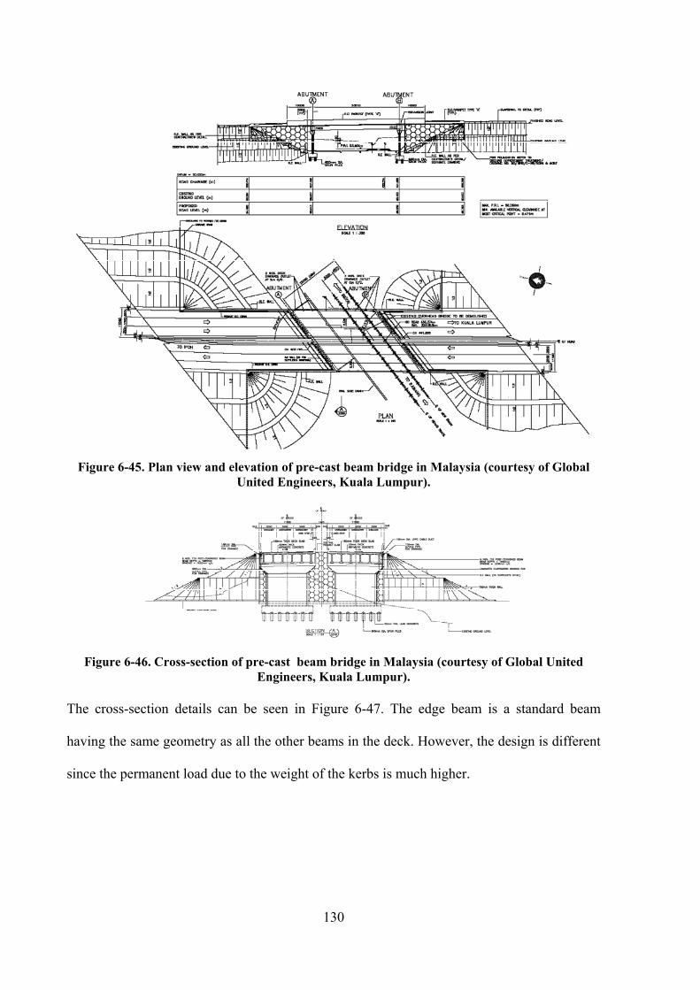
130
Figure 6-45. Plan view and elevation of pre-cast beam bridge in Malaysia (courtesy of Global
United Engineers, Kuala Lumpur).
Figure 6-46. Cross-section of pre-cast beam bridge in Malaysia (courtesy of Global United
Engineers, Kuala Lumpur).
The cross-section details can be seen in Figure 6-47. The edge beam is a standard beam
having the same geometry as all the other beams in the deck. However, the design is different
since the permanent load due to the weight of the kerbs is much higher.

131
Figure 6-47. Cross-section of pre-cast beam bridge in Malaysia (courtesy of Global United
Engineers, Kuala Lumpur).
As it is common with this type of construction, the shape of the cross-section changes as the
member approaches the supports. This is shown in Figure 6-48 with an increase in the cross-
section area which is needed to compensate the shear. The additional concrete area at the
supports is also needed to provide place for the pre-stress anchorages.
Figure 6-48. Support detail (courtesy of Global United Engineers, Kuala Lumpur).
The details for the diaphragms are shown in Figure 6-49, they are cast in-situ and create a
solid unit together with the ends of the pre-cast beams.
Figure 6-49. Diaphragm at the support (courtesy of Global United Engineers, Kuala Lumpur).

132
6.7 Europe
In Europe there are not many design regulations available. The current move is away from the
national design codes towards the Eurocode. In the research carried out Spain was identified
as a large user of the pre-cast bridge, to demonstrate methods used in span two typical
examples are presented.
The first example is the Junta de Comunidades de Castilla –La Mancha. The bridge consists
of three spans (13.0, 18.0, 13.0m) and is composed by a pre-cast pre-tensioned U-beam with
cast in-situ concrete deck connecting the girders which each other (see Figure 6-50 and Figure
6-51).
Figure 6-50. General Bridge layout (courtesy of Pedelta Engineers, Barcelona).
The cross-sections are positioned perfectly flat and the cross fall of the deck is generated by
the cast in-situ roadway slab see Figure 6-51. It should be noted that under this loading
condition a non-symmetrical situation for the permanent load is produced.
Figure 6-51. General Bridge layout (courtesy of Pedelta Engineers, Barcelona).
In longitudinal direction three simple supported girders are put next to each other .For this
example there is only pre-stressing in the bottom area of the U-beams as shown in Figure 6-52

133
with a certain continuity being created through the casting of the roadway slab as shown in
Figure 6-53.
Figure 6-52. Pre-stressing tendon layout in cross-section (courtesy of Pedelta Engineers,
Barcelona).
Figure 6-53. Support detail (courtesy of Pedelta Engineers, Barcelona).
After casting the roadway slab the three simple supported beams are continuous through the
top slab. However. This does not constitute full continuity, with only partial continuity as the
concrete will crack over the support leaving only the stiffness of the reinforcement for the
continuity effect.
The solution shown in this example is very common in the southern part of Europe and other
regions were freezing conditions are not part of the design considerations. In the colder
regions were cracking of concrete has a detrimental effect due to frozen water, road salt
during winter full continuity is required.
In case continuity must be achieved over a support an additional pre-stressing tendon is often
installed. This tendon creates a compression in the top fibre which avoids cracking of the

134
concrete. This additional pre-stressing over the negative moment region is always post-
tensioned and placed in roadway slab. These tendons may be either be straight (tendon is in
the roadway slab only) or curved. Figure 6-54 shows a detail for a curved tendon layout.
Figure 6-54. Detail for longitudinal pre-cast girder connection for full continuity (courtesy of
Pedelta Engineers, Barcelona).
The determination of the use of curved or straight tendons is up to the design engineer, but
must be determined prior to design of the members. The curved layout requires considerations
when designing the pre-cast beams as the anchorages and parts of the duct must be installed
within the beams. However, the straight tendon requires consideration of where to place the
jack or the anchorages within the slab.
Example 2:
The second example consists of a four span bridge with five parallel pre-cast pre-tensioned I-
beams as shown in Figure 6-55. The bridge is curved in plan while the girders are straight.
This results in a kinked girder axis in plan when looking at the plan view in Figure 6-55.
The general cross-section and the arrangement of the I-beams are shown in Figure 6-56. Due
to the significant cross-fall of the bridge deck the I-beam girders are all on a different level.
The pre-cast panels linking the I-beams and acting as a permanent formwork between the
webs is therefore not horizontal, but sloped.

135
Figure 6-55. Bridge in plan showing the pre-cast girders. (courtesy of Pedelta Engineers,
Barcelona).
Figure 6-56. Cross-sections of pre-cast girders. (courtesy of Pedelta Engineers, Barcelona).
Figure 6-57. Pre-stressing layout of pre-cast girders. (courtesy of Pedelta Engineers, Barcelona).
The strands are straight and partially unbonded near the supports as shown in Figure 6-57.
The change from the series of simple supported beams to a continuous girder is achieved
when casting the roadway slab. The continuity is again only partial since the concrete will
crack due to the negative moment being introduced after connecting the girder.

136
Figure 6-58. Detail of the support (courtesy of Pedelta Engineers, Barcelona).
6.8 Summary
In this chapter an brief extract from an extensive study of the use and practice of Pre-cast
Bridges world wide has been presented. This study looked at the various cross-sections, types
of pre-stressing used and other construction solutions.
The study demonstrated that there are only a few general types of cross-sections that are in
use all over the world. Figure 6-1 actually shows most of the relevant shapes. Each cross-
section can be parameterised for all dimensions. In some cases the edge cross section has a
very different and unusual shape. It was also observed that different types of pre-cast cross-
section are rarely mixed within a single structure.
The girder cross-section may change within one span, this often occurs with the web thickness
increases near the supports and is generally observed for I-beams only.
The pre-tensioning strands are straight, kinked or curved and a combination of pre- and post-
tensioning may be used depending on the application. Although it is not a standard the
continuity pre-stressing over the supports is important for colder climates.

137
Transversal pre-stressing is used in some countries, generally pre-stressing is applied to both
the roadway slab and the diaphragms.
Diaphragms are installed at quarter and/or half points of the span. Almost all bridges have a
diaphragm at the end supports stabilizing the whole bridges structure. The geometry of these
diaphragms depends on whether the support axis is skew or perpendicular to the girder axis.
The diaphragm cross-section can be considered as always being rectangular although no
typical cross-section could be found.
It appears to be common practise that panels are installed between pre-cast beams of any
shape. The structural influence of these pre-cast panels however is not significant and for the
analysis it is not necessary to consider these panels as an individual cross-section part, but as
a part of the roadway slab.
Due to the type of structure there is not much variation possible for the erection sequences
although a number of regulatory bodies do recommend a procedure. Generally the pre-cast
beams are put into position on the supports and that the roadway slab is added later. The
individual methods of the construction companies and/or manufacturers are not part of any
design guideline or standard procedure and must be considered to allow for any long-term
effects with in the design procedure.

138

139
7 Conclusion
The requirements for the modelling of multiple Tee-beam bridges for structural analysis with
a particular emphasis on design software packages have been discussed in detail in this thesis.
Experience from many practical applications has been used to describe a number of important
features, modelling techniques and pitfalls that should be considered during the analysis and
the design of multiple Tee-beam structures.
Additionally, a review of current practices in the construction of Tee-beam bridges world
wide was conducted to establish the trends, similarities and requirements in this type of
construction. While this type of construction is not new and it has been shown that many
design guidelines have been published, current methods of analysis and design rely on
numerous assumptions that decrease the efficiency of this type of structure. The information
collected in this thesis can be used by design engineers to consider all aspects and
requirements for analysing, designing and constructing these types of bridges anywhere in the
world. Furthermore, with the increase in computing power and the advances in bridge
engineering software it is not beyond reasonable expectations to develop analysis software
that will considerer all the important aspects for this type of structure and provide much more
efficient designs for the Tee-beam bridge.
A summary of these specifications listing the primary pieces of information necessary to
create a model to accurately simulate the complex behaviour of such bridges is presented
here. It is proposed that from this information, a software package with the specific task of
analysing bridges made from pre-cast pre-tensioned beams and cast-on-site roadway slabs
will be developed.
When carrying out the analysis of a Tee-beam bridge it is important to include the following
in the model. Firstly one must consider the design parameters of the bridge these parameters

140
include the types of materials, environmental conditions and the particular design code that
will be utilised.
Secondly the geometry of the bridge must be considered, generally the geometry of the bridge
is derived from a road or rail alignment given in both the plan view and elevation. For pre-
cast beam bridges a polygonal approximation must always be made, and any consideration for
the geometric requirements of pier positions and their orientations must also be made. When
considering the alignments the effects of any road widening or curved decks must also be
included in any model.
As the Tee-beam method of construction is widespread, guidelines for standardised cross-
section shapes for the pre-fabricated beams are often given by the authorities or industry.
However in analysing these cross-sections, and if necessary derivatives of these sections, the
designer should take into account the prestressing and the associated long-term effects such as
creep and shrinkage. Additionally, if the cross-section varies along the length of the beam the
model must be adjusted appropriately. For each span certain parameters need to be defined
including the number of longitudinal beams and the assignment of cross-sections for these
beams, it is also critical to understand how adjacent beams might react to any load applied to
any member on the structural system.
Specification of the exact location of the structural connection between the pre-fabricated
beams and the roadway slab must also be given, along with detailed information on the
reinforcement and the pre-stressing. The designer must understand the use of both beam and
finite elements and structural modelling elements and must be aware of the limitations and
implications of using each with in the model.
Thirdly the designer must understand the implications and effects of the loading. Permanent
and service loads must be applied to the correct structural system, and be appropriately
modelled to ensure the correct load transfer is obtained. Many of these loading conditions are

141
automatically assigned with respect to the code requirements; but the designer must be aware
that others loads may vary for each project and must be specified by the project engineer. The
Traffic loading is critical as in most cases this is the governing load case, however this
requires numerous load cases and locations thus requiring a fair degree of automation. The
design engineer must ensure that he fully understands the load cases and in particular the
location of the load trains and what effects this has on the loaded girder and the secondary
effects on the adjacent girders.
An additional aspect that must also be considered is the continuity of the deck slab over the
supports. While ignoring continuity over the supports all together and assuming series of
simply supported beams is allowable in some countries, care must be taken to control the
cracking that will occur in this region. However, in other countries particularly those with
colder climates, continuity needs to be considered. When this is the case the stiffness of link
slabs need to be considered and if continuity post-tensioning is applied then this must most
certainly be included in the structural model.
Information regarding the erection sequence must be known and included in any model.
When casting a slab on the precast member each of the two components become a composite
member with varying material properties. Consequently, the computation of time-dependent
effects such as creep and shrinkage must be considered in the design code checks for
individual construction stages.
Finally, throughout the analysis of any bridge a great number of results are generated as the
various load cases and sequences are considered. The design engineer needs to have a good
understanding of what the critical cases will be and where the critical loads occur, this is only
learnt through experience. Based on this experience a selection of appropriate details for the
final report and management of results are presented.
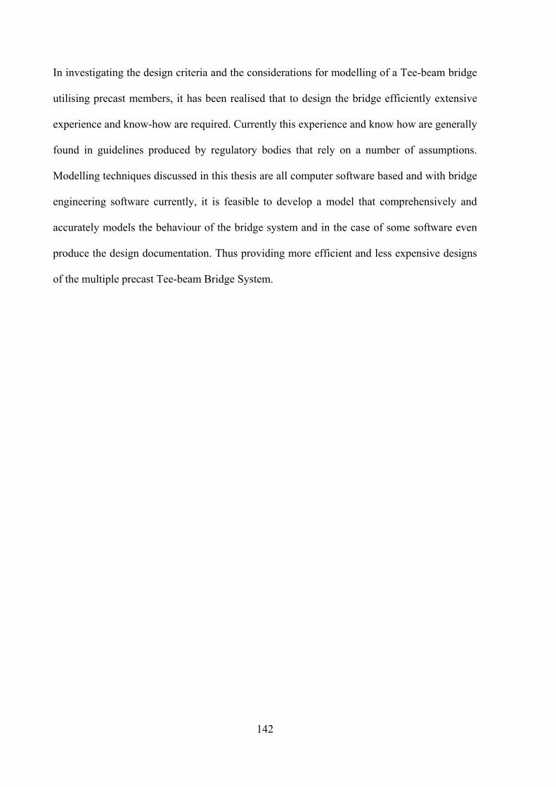
142
In investigating the design criteria and the considerations for modelling of a Tee-beam bridge
utilising precast members, it has been realised that to design the bridge efficiently extensive
experience and know-how are required. Currently this experience and know how are generally
found in guidelines produced by regulatory bodies that rely on a number of assumptions.
Modelling techniques discussed in this thesis are all computer software based and with bridge
engineering software currently, it is feasible to develop a model that comprehensively and
accurately models the behaviour of the bridge system and in the case of some software even
produce the design documentation. Thus providing more efficient and less expensive designs
of the multiple precast Tee-beam Bridge System.

143
8 References
AASHTO (1996), Standard Specifications for Highway bridges, 16th
ed., AASHTO,
Washington DC
Anderson A.R. (1972), Systems Concepts for Precast Pre-stressed Concrete Bridge
Construction, Special Report 132, Highway Research Board, Washington DC, pp. 9-21
Bangash M.Y.H. (1999), Prototype bridge structures: analysis and design, American Society
of Civil Engineers, Publications Sales Department
BS 5400: Part 4, (1990) “Code of Practice for the Design of Concrete Bridges, BD 37/88
loads for Highway Bridges, BD 57/95 design for durability”, BS 5400-4: Steel, Concrete and
Composite Bridges, Code of Practice for Design.
Campbell T.I. & Bassi K. (1994), “Comments on the new ‘Texas U-beam Bridges: An
Aesthetic and Economical Design Solution,’ by M.L. Ralls and J.J. Panek, PCI Journal, 38(5)
September-October 1993, pp 20-29, and 39(2), March-April, pp. 122-123.
Cusens A.R. & Pama R.P. (1975), Bridge Deck Analysis, John Wiley & Sons, London
CEB-FIP Model Code (1990), CEB-FIB, Bulletin d’Information n. 213/214, 1993
CEN Eurocode 2 (2002), Design of concrete structures – Part 1: General Rules and Rules for
Buildings, Comité Européen de Normalisation; prEN 1992-1-1
Deatherage J.H. and Burdette E.G. (1991), Development length and lateral spacing
requirements for pre-stressing strand for pre-stressed concrete bridge products, Final report,
Precast/pre-stressed concrete institute, University of Tennessee, Knoxville, September.
DIN 1045, Part 1 – 4, (2004) Deuschtes Normeninstitut (in German)
Dunker, K.F. and Rabbat, B.G. (1990), Highway Bridge Type and Performance Patterns,
ASCE J. Performance of constructed Facilities, 4(3), August, pp 161-173.
Hambly E.C. (1991), Bridge Deck Behaviour, Chapman & Hall, London, UK

144
Hartmann F. & Katz C., (2001), Statik mit finiten Elementen, Springer Verlag (in German).
Hewson, N.R. (2000), Design of pre-stressed concrete bridges, ASCE Press, VA, USA
Kaar P.H., LaFraugh R. and Mass M. (1963), Influence of Concrete Strength on Strand
Transfer Length, PCI Journal, 8(5), September-October, pp. 102-103
Lin T.Y. & Burns Ned H. (1981), Design of Pre-stressed Concrete Structures, John Wiley &
Sons, New York.
Mast R.F. (1989), Lateral Stability of Long Pre-stressed Concrete Beams: Part 1, PCI
Journal, 34(1), January – February, pp 70-83.
Miehlbradt F. & Fraunhofer H. (1985), “Technische Baubestimmungen auf der Grundlage
von CEB und FIP.“ IRB Verlag, (in German)
Naaman A.E., Hamza A.M. (1991), Evaluation of Pre-stressing Losses for Partially Pre-
stressed High Strength Concrete beams, Report no. UMCE 91-18, Department of Civil and
Environmental Engineering, University of Michigan
Narendra Taly (1998), Design of modern Highway bridges, The McGraw-Hill Companies,
United States.
Neville A.M. (1995), Properties of Concrete, 4th
edition, New York, and Longman, England,
844 pp.
Nilson Arthur H. (1978), Design of prestressed concrete, John Wiley & Sons, London
NZS 3100 1 & 2 1995 (NZS) A2, Concrete Structures Standard
O’Brien E.J. & Keogh D.L. (1998), Upstand Finite Element Analysis of Slab Bridges,
Computers and Structures, v69, pp 671-683
Pircher G. & Pircher M. (2004), “Computer-aided design and analysis of multiple Tee-beam
bridges”, Proceedings: Fifth Austroads Bridge Conference, Hobart, Australia

145
Pircher H. (1994), “Finite Differences to Simulate Creep and Shrinkage in Pre-Stressed
Concrete and Composite Structures“, Proceedings: Computational Modelling of Concrete
Structures, Innsbruck, 579-588
Ralls M.L., Ybanez L., and Panek J.J., (1993), “The New Texas U-Beam Bridges: An
Aesthetic and Economical Design Solution,” PCI J. 38(5) September-October, pp 20-29
Rebentrost M., (2005), Design and construction of the first ductal bridge in New Zealand,
Concrete 05, 22nd biannual conference, Melbourne.
RTA (2004), Standard Drawings, RTA Bridge Section, Paramatta.
Ryall M.J. , Parke G.A.R. and Harding J.E. (2003), Manual of Bridge Engineering, Published
by Thomas Telford Publishing, London.
Schofield E.R. (1948), The first pre-stressed bridge in the US, Eng. News-Record, December,
pp. 16-18, Construction starts on Pre-stressed Concrete Bridge in Philadelphia, ASCE Civ.
Eng., July, p 32.
Sedlacek G. & Bild J. (1988), Anwendung von Finite-Elemente-Berechnungen bei der
Entwicklung von Bemessungsregeln in den Eurocodes für den Verbundbau. Finite-Elemente-
Anwendung in der Baupraxis, Reserach study at University Aachen, Germany (in German).
Slatter R.E. (1980), Bridge Aesthetics, Final report of the 11th
Congress, Vienna, Austria,
IABSE, Zurich, Switzerland, pp 115-120.
Standard Australian (2004), AS5100 Bridge Design, Standards Australia, Sydney.
Steinman D.B. & Watson S.R (1957), Bridges and their Builder, Harcourt, Brace & Co., New
York.
Taylor H. & Tarmac M., (1998), Precast concrete limited: The fourth in a series of Current
Practise sheets prepared by the concrete bridge development group, the Structural Engineer,
Vol. 76, No.21, November 1998.
146
Unterweger H. ,2001, Globale Systemberechnung von Stahl- und Verbundbruecken
Leistungsfaehigkeit einfacher Stabmodelle, Professorial Thesis, Graz University of
Technology, Austria (in German).
Yamane, Tadros and Arumugasaamy (1994), Short to Medium Span Precast Prestressed
Concrete Bridges in Japan, PCI Journal, vol 39, no. 2, March/April 1994, pp 74-100.
Zemajtis Jerzy, (1998), Modelling the time to Corrosion Initiation for concretes with Mineral
Admixtures and/or Corrosion Inhibitors in Chloride-Laden Environments. Dissertation
Faculty of Polytechnic Institute, State University, Blaksburg, Virgina
Zienkiewicz O.C., Taylor R.L. (1991), The finite Element Method, Fourth Edition, McGraw-
Hill Book Company, London
Homepages:
Ministry of Transportation – California – CALTRANS: www.dot.ca.gov
Ministry of Transportation – Florida: www.dot.state.fl.us
Ministry of Transportation –Minnesota: www.dot.state.mn.us
Ministry of Transportation –Washington: www.wsdot.wa.gov
With special thanks
Global United Engineers, Kuala Lumpur, Malaysia
Pedelta Engineers, Barcelona, Spain.

147