computer-integrated femoral head fracture reduction … · computer-integrated femoral head...
TRANSCRIPT

Computer-Integrated Femoral Head Fracture Reduction System
M.Mitsuishi1, N.Sugita1, S.Warisawa1, T.Ishizuka1, T.Nakazawa2, N.Sugano3, K.Yonenobu4 and I.Sakuma5
1 The University of Tokyo, 2 THK Co. Ltd.3 Osaka University, 4 Osaka Minami National Hospital,
5 The University of Tokyo

Background

Conventional method and its problems
The force that must be exerted by the surgeons is large while pulling the inferior branch.
Surgeons, medical staffs and patients are exposed to radiation during the operation.
Fluoroscopy
Reduction device
Reduction accuracy depends on the ability of the surgeon.
(1) Separation of a piece of bone by pulling the leg (inferior branch)
(2) Reduction motion by pulling and rotation of an inferior branch
(3) Intra-operative confirmation by X-ray

Fracture reduction robot system construction

Schematic diagram of the systemThe optimum reduction path is calculated preThe optimum reduction path is calculated pre--operatively operatively using the CT and Xusing the CT and X--ray images at the navigation system.ray images at the navigation system.The calculated path is sent to the reduction robot.The calculated path is sent to the reduction robot.The reduction motion is performed by the robot.The reduction motion is performed by the robot.

Solutions(1) Preoperative full 3D reconstruction(2) Preoperative path planning(3) 6 d.o.f. reduction robot(4) Multi operation modes(5) Fail-safe mechanism
Automatic mode Power assisted mode JOG mode

Layout of the system3D fluoroscopy imaging system
Carbon operation table Reduction robot
Patient Medical doctor

System overviewFluoroscopy
imaging system
Carbon operation table
Reduction robot
Optical 3D tracking system
Navigation system
Patient

Fracture reduction system

Fracture reduction robot
boot Pitch
Roll
Telescopic
caster
ForceSenser
Handle
Air Lift(built-in)
‘Holizontal is perpendicular to the paper)
Swing-Arm for connection to the surgical table
l=2267
h=10
17
880
(w=663)
Axis Stroke
Horizontal 202.43mm Telescopic 182.44mm
Vertical 303.12mm Pitch 679.84mrad Roll 4882.67mrad Yaw 672.80mrad
Weight 250kg
Vertical
•The axes of all the rotational d.o.f. intersect at the same point using a hollow motor.•Attaching and detaching operations should be easy while the robot is connected with the existing operation table.
•Fail-safe mechanism is necessary.•The same position can be maintained by a lift after the determination of a fracture reduction robot.•The motion of the robot must be synchronized with that of an operation table while moving up and down.
Yaw

SpecificationSpecificationStrokeX:±150 mm,Y:-10~+300 mm,Z:-10~+300 mmA:±20 deg.,B:±25 deg.,C:±135 deg.
Force sensorFx, Fy:400 N,Fz:800 NMx, My, Mz:40 Nm
Fail-safe mechanismY:300 N,+100 mm, -30 mmB:28 Nm±135 deg.
A-axis
Z-axis
Y-axis
X-axis
C-axis
B-axis

Overview of the fracture reduction robot
Teaching pendant
Force sensor
FixtureEmergency stop bottom
Foot switch for the power assisted mode Connecting arm

Robot system controllerRobot system controllerReal Time Linux
Robot Control Task
Socket communi-cation
Teaching pendantcontrol task

FailFail--safe mechanismsafe mechanism1. High rigidity should be maintained in the normal state.2. Large displacement occurs when an excessive force is
applied to the system.3. Emergency signal is generated and the system is stopped.4. The system returns to its normal state when the excessive
force is removed.
Concept
Configuration

Operation modes
JOG modePower assisted mode
Automatic (NAVI) mode

JOG modeJOG mode
Interactive motion control using a teaching Interactive motion control using a teaching pendantpendantStep motionStep motionUseful for preparation of the surgeryUseful for preparation of the surgery

Power assisted modeTo reduce the load on a surgeon when pulling and rotating the patient’s inferior branch– Approaching the fixture device to a foot
To provide the same adjustment environment as the conventional one by holding a fixture device– Separating fracture segments
To move the inferior branch to an arbitrary position and posture

Power assisted modePower assisted mode3 different viscosities were prepared.
1. 1. UltraUltra--soft modesoft mode–– Appropriate for Appropriate for
the wide range the wide range motion (coarse motion (coarse positioning)positioning)
2. 2. Soft modeSoft mode–– Not necessaryNot necessary
3. 3. Hard modeHard mode–– Suitable for the Suitable for the
precise precise positioningpositioning
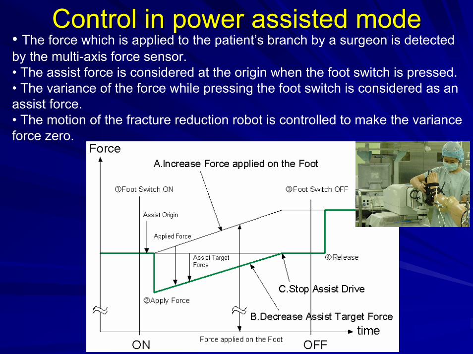
Control in power assisted modeControl in power assisted mode• The force which is applied to the patient’s branch by a surgeon is detected by the multi-axis force sensor.• The assist force is considered at the origin when the foot switch is pressed.• The variance of the force while pressing the foot switch is considered as an assist force.• The motion of the fracture reduction robot is controlled to make the variance force zero.

Automatic (NAVI) modeAutomatic (NAVI) modeUsed in the fracture reduction processUsed in the fracture reduction processControl points scheduled by NAVIControl points scheduled by NAVISmooth motion requiredSmooth motion requiredThe third order The third order splinespline curve interpolationcurve interpolationVelocity control: position not guaranteedVelocity control: position not guaranteed
t [sec]v

Video of automatic modeVideo of automatic mode

Experiments

Synchronized motion of the robot with an operation table
The fracture reduction robot moves up and The fracture reduction robot moves up and down down synchroniticallysynchronitically with an operation table by with an operation table by the operation to the operation table.the operation to the operation table.

Fail-safe mechanism

Evaluation of the fail-safe mechanism
A-axisB-axis
C-axisX-axis
Y-axis
Z-axis
Active point Active point
Loading LoadingRefuge motion,Excessive force absorption
Refuge motion,Excessive force absorption
Rated valueY-axis: 300 NB-axis: 28 Nm
(1) Y-axis, minus direction (2) B-axis, minus direction

Power assisted mode

Evaluation of the power assisted function (B-axis, ultra-soft mode)
ON OFFON OFFFoot switch Foot switch
(1) Position (2) Force

Evaluation of the power assisted function (B-axis, hard mode)
ON OFFON OFFFoot switch Foot switch
(1) Position (2) Force

Biomechanical data acquisition to apply the developed system
for the clinical use

Pain
Pain
Limit
Limit
Motion range of the inferior branch (Subject A: Female, Normal volunteer)(a) Right leg external rotation
(b) Right leg internal rotation

Motion range of the inferior branch (Subject A: Female, Normal volunteer)
LimitPain in pubis
Pain in knee joint
(c) Right leg traction

• Limit value for internal rotation is smaller than that for external rotation.• Limit value is different for the right and the left legs.
Motion range of the inferior branch (Subject A: Female, Normal volunteer)(d) Left leg external rotation
(e) Left leg internal rotation
Limit
Limit
Pain in knee joint
Pain in hip joint

Motion range of the inferior branch (Subject A: Female, Normal volunteer)
LimitPain in knee joint
Pain in hip joint
(f) Left leg traction

ConclusionsThe authors have developed a robot system for femoral head fracture reduction.The system consists of a navigation system, a robotic system, an X-ray system, and an operation table.The robot has 6 d.o.f., such as three translation d.o.f. and three rotational d.o.f.Three operating modes were prepared: JOG mode, power assisted mode, and an automatic mode.The biomechanical data to apply the developed system for clinical use were obtained.