computer hardware and system software concepts · assembler . two - pass assembler: 1. in pass-one...
TRANSCRIPT
1
Computer Hardware and System Software ConceptsIntroduction to concepts of System Software/Operating System
Welcome to this course on Computer Hardware and System Software Concepts
2
2ER/CORP/CRS/OS09/003
Version No: 2.0Copyright © 2004,
Infosys Technologies Ltd
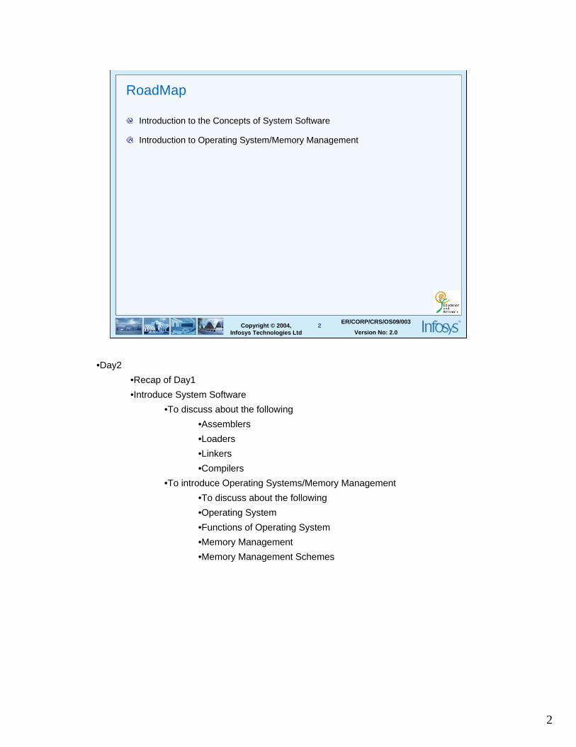
RoadMap
Introduction to the Concepts of System Software
Introduction to Operating System/Memory Management
•Day2
•Recap of Day1
•Introduce System Software
•To discuss about the following
•Assemblers
•Loaders
•Linkers
•Compilers
•To introduce Operating Systems/Memory Management
•To discuss about the following
•Operating System
•Functions of Operating System
•Memory Management
•Memory Management Schemes

3
3ER/CORP/CRS/OS09/003
Version No: 2.0Copyright © 2004,
Infosys Technologies Ltd
System Software
System programs which provide a more convenient environment for program
development and execution
Example
– Compilers
– Assemblers
– Loaders
– Linkers
– Operating System
Motivate, once again, what is the difference application and systems software.

4
4ER/CORP/CRS/OS09/003
Version No: 2.0Copyright © 2004,
Infosys Technologies Ltd
Translators
A program which converts a user’s program written in some language to
another language.
The language in which the user’s program is written is called the source
language
The language to which the source language is converted is called the target
language
Motivate for translators:
If there is a processor that can directly execute programs written in the source language, then, there is no need to translate the source program into the target language. Translation is thus used only when a processor is available for the target language but not for the source language. Running the translated program will give exactly the same result as the execution of the same program would have given had the processor for it was available. i.e. of course if the translation was done correctly.
Example: Compilers, Assemblers etc
There is an important difference between translation and interpretation. In the former, the original program is first converted to an equivalent program called an object program. Then this object program is executed i.e. only after the translation has been completed. Hence, the original program in the source language is not directly executed. Thus, translation comprises of two steps i.e
1. Generation of an equivalent program in target language
2. Execution of the generated program
Interpretation consists of only one step i.e. executing the original source program

5
5ER/CORP/CRS/OS09/003
Version No: 2.0Copyright © 2004,
Infosys Technologies Ltd
Translators
Source Program
Target Program

6
6ER/CORP/CRS/OS09/003
Version No: 2.0Copyright © 2004,
Infosys Technologies Ltd
Translator
Source Program (High level language)
Target Program (Object /Exe code )
Compiler
When a source program is a high level language such as COBOL and the target program is a numerical machine language then the translator is called as a compiler.

7
7ER/CORP/CRS/OS09/003
Version No: 2.0Copyright © 2004,
Infosys Technologies Ltd
Translator
Source Program (Assembly language)
Target Program (Machine language )
Assembler
When a source program is a assembly language and the target program is a numerical machine language then the translator is called as a assembler.
Assembly language is basically a symbolic representation for a numerical machine language

8
8ER/CORP/CRS/OS09/003
Version No: 2.0Copyright © 2004,
Infosys Technologies Ltd
Assembly language
A convenient language using mnemonics (symbolic names and symbolic
addresses) for coding machine instructions
The assembly programmer has access to all the features and instructions
available on the target machine and thus can execute every instruction in the
instruction set of the target machine
Some other characteristics:
• Assembly language programming is difficult
• Takes longer time
• Takes longer to debug
• Difficult to maintain
Why go for assembly language programming?
1. Performance issues – For some applications, speed and size of the code are critical. An expert assembly language programmer can often produce code that is much smaller and much faster than a high level programmer can. Example – embedded applications such as the code on a smart card, the code in a cellular telephone, BIOS routines, inner loops of performance critical applications etc.
2. Access to the machine – Some procedures need complete access to the hardware, something which is impossible in high level languages. Example – low level interrupt and trap handlers in an operating system etc.

9
9ER/CORP/CRS/OS09/003
Version No: 2.0Copyright © 2004,
Infosys Technologies Ltd
Assembly language (Example)
Consider the computation of a formula N=I+J illustrated using instructions from Motorola
68030
Label OPCODE OPERANDS COMMENT
TEMP : MOVE.L I, D0 ; Load I into Reg D0
ADD.L J, D0 ; ADD J to D0
MOVE.L D0,N ; Store I+J in N
I: DC.L 3 ; Reserve 4 bytes initialized to 3;
J: DC.L 3 ; Reserve 4 bytes initialized to 3;
N: DC.L 0 ; Reserve 4 bytes initialized to 0;
Assembly language format:
The format of a typical assembly language program consists of
•Label field – provides symbolic names for memory addresses which is needed onexecutable statements so that the statements can be jumped to. It also permits the data stored there to be accessible by the symbolic name. Example: TEMP,FORMUL etc
•Operation field – contains a symbolic abbreviation for the opcode or a pseudo-instruction. Example: MOVE, ADD etc.
•Operands field – specifies addresses or registers used by operands of the machine instruction. Example: D0,R1,R2 etc.
•Comment field – is used for documentation purposes.
Explanation of the example in the slide above:
TEMP : It is a label field
MOVE : An instruction that moves the first arg to second arg
ADD : Adds the contents of first arg to second arg and stores it in the second arg
I : Yet another label
DC (Define Constant) is a pseudo instruction which is a command to the assembler to interpret it. The suffix .L denotes long (i.e. 4 bytes) associated with that opcode.
In the above example one important point is worth noting. How does the assembler know what is stored in a location N. such a reference which is used even before it is defined is called a forward reference (next slide).

10
10ER/CORP/CRS/OS09/003
Version No: 2.0Copyright © 2004,
Infosys Technologies Ltd
Assembly language (The Forward Reference)
is a reference which is used even before it is defined
Can be handled in two ways:
– Two pass assembler
– One pass assembler
Each reading of the source program is called a pass. Any translator which reads the input program once is called a one-pass assembler and if it reads twice is called a two-pass assembler.
Two - pass assembler:
1. In pass-one of a two-pass assembler, the definitions of symbols, statement labels etcare collected and stored in a table known as the symbol table .
2. In pass-two, each statement can be read, assembled and output as the values of all symbols are known.
This approach is thus quite simple though it requires an additional pass.
One - pass assembler:
The assembly program is read once and converted to an intermediate form and thereafter stored in a table in memory

11
11ER/CORP/CRS/OS09/003
Version No: 2.0Copyright © 2004,
Infosys Technologies Ltd
Loaders
Are system programs
Loads the binary code in memory (main)
Transfer the control to 1st instruction
There are various loading schemes:
1. Assemble-and-go loader: The assembler simply places the code into memory and the loader executes a single instruction that transfers control to the starting instruction of the assembled program. In this scheme, some portion of the memory is used by the assembler itself which would otherwise have been available for the object program.
2. Absolute loader: Object code must be loaded into the absolute addresses in the memory to run. If there are multiple subroutines, then each absolute address has to be specified explicitly.
3. Relocating loader: This loader modifies the actual instructions of the program during the process of loading a program so that the effect of the load address is taken into account.

12
12ER/CORP/CRS/OS09/003
Version No: 2.0Copyright © 2004,
Infosys Technologies Ltd
Linkers
Are system programs that accounts for and reconciles all address references
within and among modules.
Example
Large Program
main sort search count
In actual practice, a complete program is built from many smaller routines possibly by many people. All these routines have to be connected logically and linked to form a single program. A linker is a systems program that accounts for and reconciles all address references within and among modules and replaces those references with a single consistent scheme of relative addresses. Linking is done after the code is generated and is closely associated with a loader.
Compilers and translators basically translate one procedure at a time and put the translated output on the disk. All the translated procedures have to be located and linked together to be run as a unit called an executable binary program. In MS-DOS, Windows 95/98 etc object modules have extension .obj and the executable binary programs have .exe extension. In UNIX, object modules have .o extension and executable programs have no extension.
Linking is of two main types:
1. Static Linking: All references are resolved during loading at linkage time
2. Dynamic Linking: References made to the code in the external module are resolved during run time. Takes advantage of the full capabilities of virtual memory. The disadvantage is the considerable overhead and complexity incurred due to postponement of actions till run time.
13
13ER/CORP/CRS/OS09/003
Version No: 2.0Copyright © 2004,
Infosys Technologies Ltd
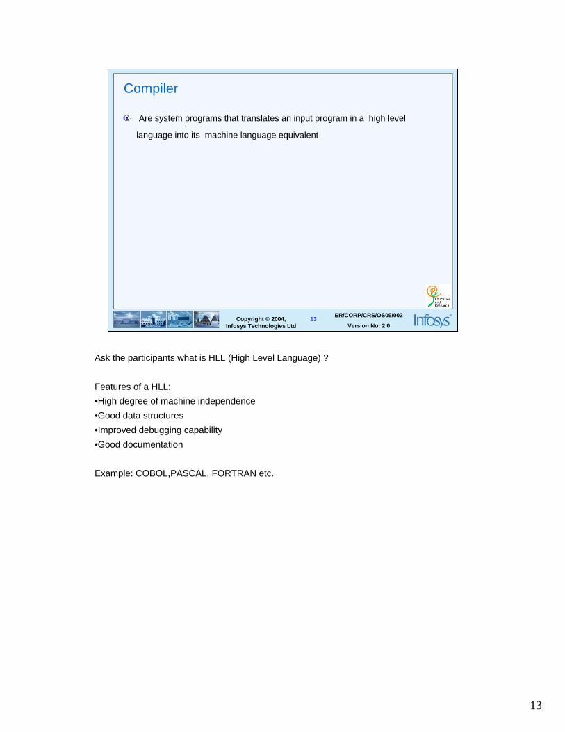
Compiler
Are system programs that translates an input program in a high level
language into its machine language equivalent
Ask the participants what is HLL (High Level Language) ?
Features of a HLL:
•High degree of machine independence
•Good data structures
•Improved debugging capability
•Good documentation
Example: COBOL,PASCAL, FORTRAN etc.

14
14ER/CORP/CRS/OS09/003
Version No: 2.0Copyright © 2004,
Infosys Technologies Ltd
Phases in a compiler
Lexical analysis
Syntactic analysis
Semantic analysis
Intermediate code generation
Code optimization
Code generation
Compilers are complex system programs. Hence, they are often broken into several phases to accomplish the task. The phases of a compiler are mentioned in the slide above. We shall be interested in looking into the functionality of each slide rather than the concerned algorithms used in implementing the phases. Each phase is an independent task in the compilation process.

15
15ER/CORP/CRS/OS09/003
Version No: 2.0Copyright © 2004,
Infosys Technologies Ltd
Compiler (Front - End )
Largely dependent on the source language
Independent of the target machine
Comprises the first three phases viz.,
– Lexical Analysis
– Syntactic Analysis
– Semantic Analysis
Sometimes the intermediate code generation phase is also included
Most of the times, the phases of a compiler are collected into a front-end and a back-end. The front-end comprises of those phases or at times also parts of the phases which depend on the source language and are independent of the target machine. These include lexical analysis, syntactic analysis, creation of symbol table, semantic analysis and generation of intermediate code. It also includes some amount of error handling and code optimization that goes along with these phases.
16
16ER/CORP/CRS/OS09/003
Version No: 2.0Copyright © 2004,
Infosys Technologies Ltd
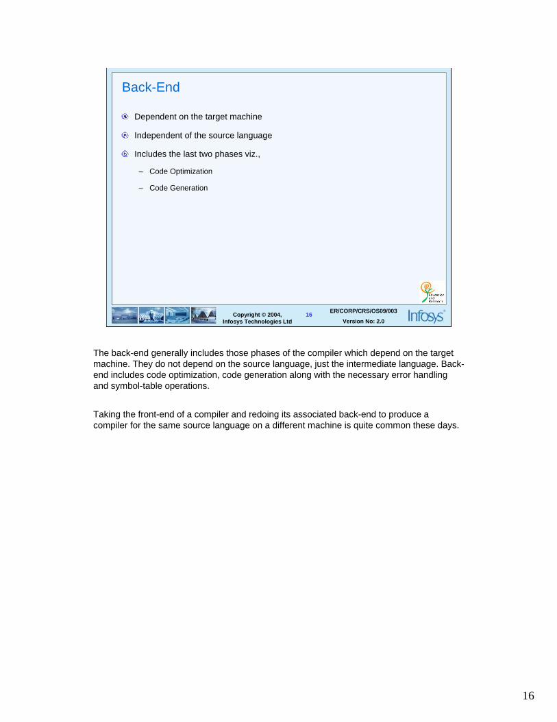
Back-End
Dependent on the target machine
Independent of the source language
Includes the last two phases viz.,
– Code Optimization
– Code Generation
The back-end generally includes those phases of the compiler which depend on the target machine. They do not depend on the source language, just the intermediate language. Back-end includes code optimization, code generation along with the necessary error handling and symbol-table operations.
Taking the front-end of a compiler and redoing its associated back-end to produce a compiler for the same source language on a different machine is quite common these days.

17
17ER/CORP/CRS/OS09/003
Version No: 2.0Copyright © 2004,
Infosys Technologies Ltd
Lexical Analysis
Scans the source program into basic elements called tokens
Prepares the symbol table which maintains information about tokens
Eliminates whitespace characters such as comments, blanks and tabs
Lexical Analyser is also called as linear analysis or a scanner. The input program which consists of a stream of characters is read from left to right and grouped into tokens. Tokens are mainly of two kinds viz.,
1. Fixed elements of the language such as keywords, vocabulary of the language, operators, signs etc
2. Identifiers and constants
EXAMPLE:
IF ( x < 5.0 ) THEN x=x+2 ELSE x=x-3;
TOKENS:
Keywords : IF, THEN, ELSE
Identifier(s) : x
Constants : 2, 3, 5.0
The blanks separating these tokens would normally be eliminated during lexical analysis.
Nowadays, there are tools to do this phase efficiently. For e.g. in Unix systems, a standard tool called lex is available for this purpose.

18
18ER/CORP/CRS/OS09/003
Version No: 2.0Copyright © 2004,
Infosys Technologies Ltd
Syntax Analysis
Reorganizes major constructs and groups them
Calls the appropriate actions corresponding to each construct
Ascertains the legality of every statement
Output of this phase are parse trees
Syntax analysis is also known as parsing or hierarchical analysis.
It basically involves grouping of the statements into grammatical phrases that are used by the compiler to generate the output finally. The grammatical phrases of the source program are usually represented by a parse tree( A parse tree is a structural representation of the input being parsed) as shown below:
Example:Structure Of Statement( x= 2* 3.0 + y)
Assignment statement=
/ \identifier expression
| / | \x expression + expression
/ | \ |expression * expression identifier
| | | integer real y
| | 2 3.0
Nowadays, there are tools to generate parsers. For e.g. in Unix systems, a tool called as YACC (Yet Another Compiler Compiler) is available for this purpose.

19
19ER/CORP/CRS/OS09/003
Version No: 2.0Copyright © 2004,
Infosys Technologies Ltd
Semantic Analysis
Looks into the static meaning of the program
Gathers type information for the subsequent code generation phase
Checks whether the type of variables used in the program is consistent with the type defined in the declaration.
Example:
If a variable is defined as type char, then it is not permitted to do arithmetic operations on that variable.
20
20ER/CORP/CRS/OS09/003
Version No: 2.0Copyright © 2004,
Infosys Technologies Ltd
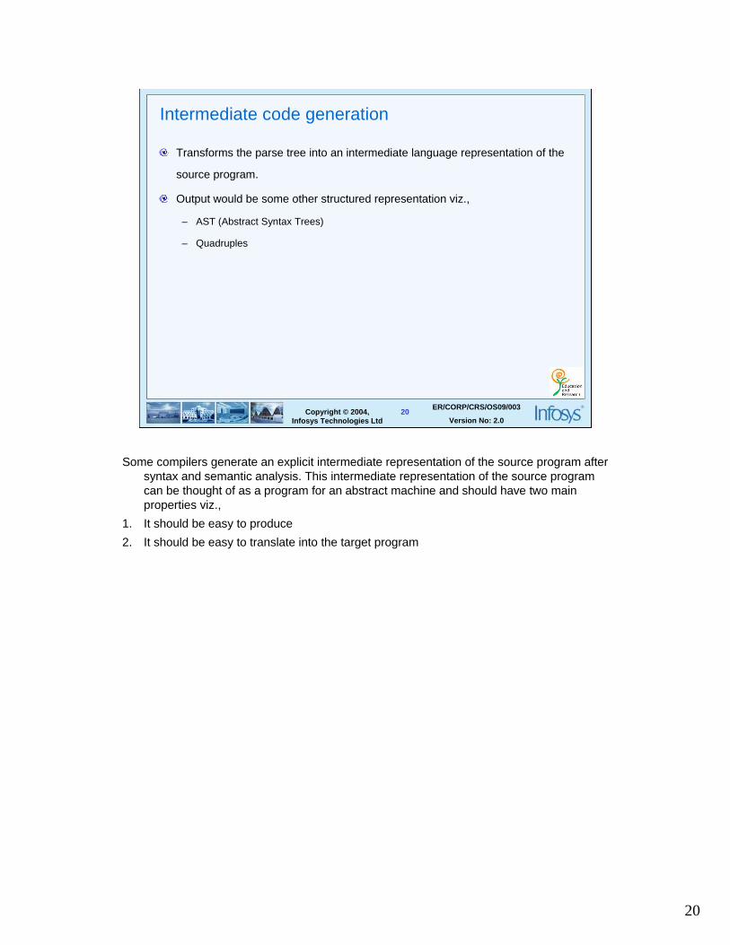
Intermediate code generation
Transforms the parse tree into an intermediate language representation of the
source program.
Output would be some other structured representation viz.,
– AST (Abstract Syntax Trees)
– Quadruples
Some compilers generate an explicit intermediate representation of the source program after syntax and semantic analysis. This intermediate representation of the source program can be thought of as a program for an abstract machine and should have two main properties viz.,
1. It should be easy to produce
2. It should be easy to translate into the target program

21
21ER/CORP/CRS/OS09/003
Version No: 2.0Copyright © 2004,
Infosys Technologies Ltd
Necessity for intermediate code generation
n machines
m languages
Let us consider the situation given in the slide above. Suppose, we have to write a complier for m languages targeted for n machines. The obvious approach would be to write m*n compilers.

22
22ER/CORP/CRS/OS09/003
Version No: 2.0Copyright © 2004,
Infosys Technologies Ltd
Intermediate code generation
INTERMEDIATE CODE
m languages
n machines
...................
....................
An intermediate language avoids most of the problems. It allows a logical separation between machine independent and dependent phases and facilitates optimization. All we have to do is to choose a rich intermediate language that would bridge both the source programs and the target programs.
Find out how many front-ends and back-ends would be required in the above example shown in the slide.
Intermediate representation has a variety of forms. There are also many algorithms for generating intermediate codes for typical programming language constructs.

23
23ER/CORP/CRS/OS09/003
Version No: 2.0Copyright © 2004,
Infosys Technologies Ltd
Code Optimization
Transforms the intermediate code to improve the execution time and memory
space usage
Examples
– Common sub-expression elimination
– Dead Code Elimination
– Loop optimization
Common Sub - Expression Elimination:•Avoid re-computation of expressions •Make use of previously computed valueExample:
x = 2*i y = 2*i z = i*2
Transform y = x and z = x at appropriate points or detect i* 2 as a common expression
Dead Code EliminationConsider the following fragment:
..........x = 10 ;y = .... ;
..........if ( x < 100 ) then y = y + 5 else y = y - 5
else branch will never get executed since the value of ‘x’ cannot be greater than or equal to 100
Loop Optimization:When a program is in execution, a lot of time is spent in loops. There are various ways to perform optimizations inside the loop. For e.g. If there is a statement such as, TEMP =5, inside a loop which is not affected by other statements, then this can be moved outside the loop. Such an optimization is called as code motion.

24
24ER/CORP/CRS/OS09/003
Version No: 2.0Copyright © 2004,
Infosys Technologies Ltd
Code Generation
Generates the code for the target machine
Translates intermediate code to a sequence of machine instructions that
perform the desired task
Code generator has knowledge of target machine
– About the number of registers
– special registers
– addressing modes etc.
The final phase of the compiler is generation of the target code which consists normally consists of relocatable machine code or assembly code. Memory locations are selected for all the variables used by the program. The intermediate instructions are then translated into a sequence of machine instructions that perform the task.
Example:
Expression : x = 2 * 3.0 + y
Generated code:
LOAD R1 , 2
MUL R1 , 3.0
ADD R1 , y
STORE x
In the first instruction, 2 is loaded into register R1. The second instruction multiplies the value 3.0 to the value stored in register R1. The third instruction adds the value in y to the previous result. The final result is stored in x.

25
25ER/CORP/CRS/OS09/003
Version No: 2.0Copyright © 2004,
Infosys Technologies Ltd
Support modules
Provide additional services of storage allocation and error indication which is
required by a compiler.
Example
– Symbol table
– Error processing
The support modules interact with all the six phases of a compiler.
26
26ER/CORP/CRS/OS09/003
Version No: 2.0Copyright © 2004,
Infosys Technologies Ltd
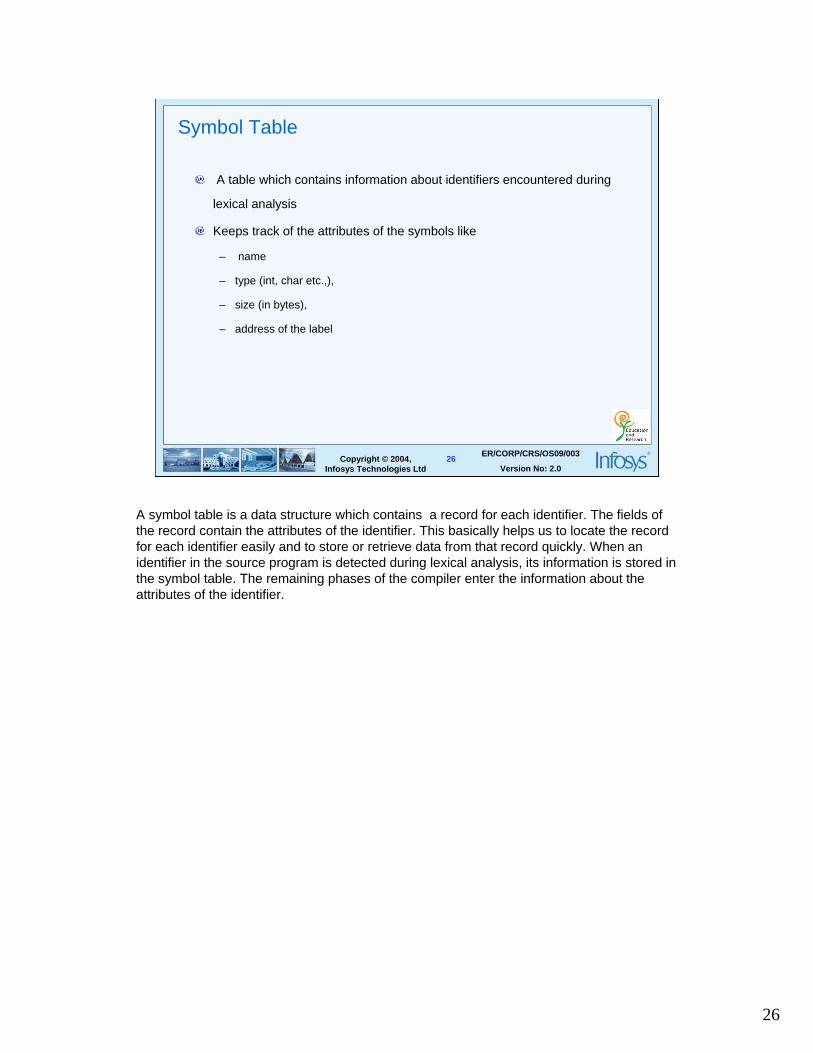
Symbol Table
A table which contains information about identifiers encountered during
lexical analysis
Keeps track of the attributes of the symbols like
– name
– type (int, char etc.,),
– size (in bytes),
– address of the label
A symbol table is a data structure which contains a record for each identifier. The fields of the record contain the attributes of the identifier. This basically helps us to locate the record for each identifier easily and to store or retrieve data from that record quickly. When an identifier in the source program is detected during lexical analysis, its information is stored in the symbol table. The remaining phases of the compiler enter the information about the attributes of the identifier.

27
27ER/CORP/CRS/OS09/003
Version No: 2.0Copyright © 2004,
Infosys Technologies Ltd
Error Processing
Error reporting
– Giving the error number and pinpoints the appropriate place in the source where the
error has been detected
Error recovery
– After reporting an error, continues translation
Error processing is required at almost every stage. One an error is detected, error processing module generates an error message for the user. Error processing is of two types viz.,
1. Error Reporting
2. Error Recovery
Error Reporting - involves getting the line number and pinpointing the appropriate place in the source where exactly the error has been detected.
Error Recovery – After reporting an error, error processing attempts to either correct or eat up certain lexumes till a certain point from where it can pretend that nothing has gone wrong and continue translation.

28
28ER/CORP/CRS/OS09/003
Version No: 2.0Copyright © 2004,
Infosys Technologies Ltd
Interpreter
Is a systems program that looks at and executes programs on a line-by-line
basis rather than producing object code
Slower than compiled code
Used in test environments as overhead of compilation is not there
Generally not recommended for production programs
Each line is scanned, parsed and executed before moving to the next line.

29
OPERATING SYSTEMSMemory Management
Introduction to Operating Systems
Introduction to the Concepts of Memory Management

30
30ER/CORP/CRS/OS09/003
Version No: 2.0Copyright © 2004,
Infosys Technologies Ltd
Operating systems
A program which acts as an interface between the user and the computer and
provides an environment in which a user can execute programs
Viewed as a Resource Allocator or Resource Manager
– Memory
– Processors
– Peripherals
– Information
Primary Goal of an Operating System is convenience for the user.
Secondary Goal is efficient operation of the computer system.
Resource Examples Managers
Memory Primary, Secondary Memory Management
Processors CPU, I/O Process Management
Peripherals Terminal, Printer, Tape Device Management
Information Files, Data File Management
Examples:
•MS-DOS
•OS/ 2
•WINDOWS 3.X
•WINDOWS 95
•WINDOWS NT
•UNIX

31
31ER/CORP/CRS/OS09/003
Version No: 2.0Copyright © 2004,
Infosys Technologies Ltd
Memory management
Plays an important role as utilization of memory is crucial to the performance of
the system
– Allow as many user jobs as possible to be active
– Respond to changes in memory demand by individual user jobs
– Prevent unauthorized changes to a user job’s memory region
– Implement allocation and addressing as efficiently as possible
The computer must keep several processes in memory at the same time to improve the CPU utilization and the speed of the response of the computer to its users. Memory management discusses various ways to manage memory.

32
32ER/CORP/CRS/OS09/003
Version No: 2.0Copyright © 2004,
Infosys Technologies Ltd
Memory management SCHEMES
Single Contiguous allocation
Partitioned allocation
Relocatable Partitioned allocation
Simple Paged allocation
Demand Paging
Segmentation
There are various memory management schemes as mentioned in the slide above. Each scheme has its own advantage and disadvantage. Selection of a particular technique depends on various factors such as hardware support, extent of memory available etc.

33
33ER/CORP/CRS/OS09/003
Version No: 2.0Copyright © 2004,
Infosys Technologies Ltd
User’s job
os
Wasted
Memory
Single Contiguous Allocation
In single contiguous allocation, the user program is given complete control of the CPU until completion or an error occurs.
Advantages:
Very simple to implement
Disadvantages:
Leads to uniprogramming
Leads to wastage of space
Leads to wastage of time (During any I/O operation CPU has to wait till I/O is finished)
34
34ER/CORP/CRS/OS09/003
Version No: 2.0Copyright © 2004,
Infosys Technologies Ltd
Partitioned Allocation
Fixed Partitioned allocation
Variable Partitioned allocation
To solve the problem of space and time usage, let us break the memory into various partitions. This allows several user jobs to reside in the memory.
There are 2 main kinds of partitions viz., Fixed and Variable
35
35ER/CORP/CRS/OS09/003
Version No: 2.0Copyright © 2004,
Infosys Technologies Ltd
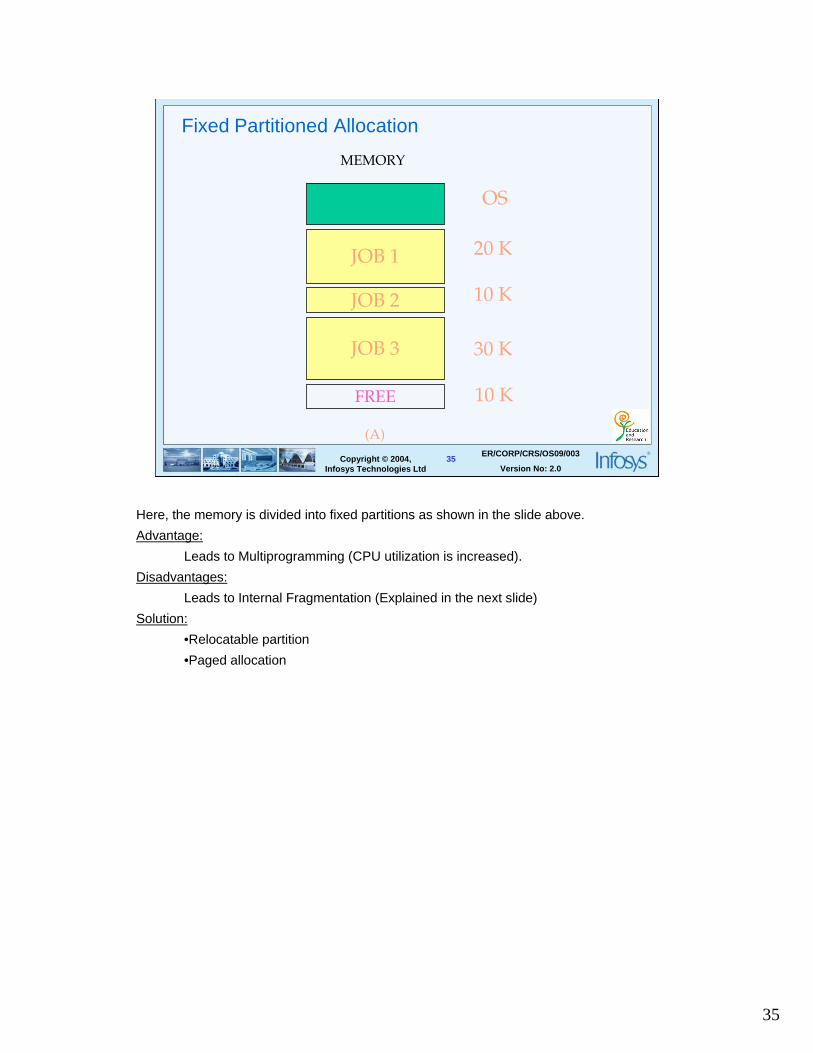
Fixed Partitioned Allocation
JOB 1
JOB 2
JOB 3
FREE
MEMORY
OS
20 K
10 K
30 K
10 K
(A)
Here, the memory is divided into fixed partitions as shown in the slide above.
Advantage:
Leads to Multiprogramming (CPU utilization is increased).
Disadvantages:
Leads to Internal Fragmentation (Explained in the next slide)
Solution:
•Relocatable partition
•Paged allocation

36
36ER/CORP/CRS/OS09/003
Version No: 2.0Copyright © 2004,
Infosys Technologies Ltd
Fixed Partitioned Allocation
JOB 1
JOB 2
JOB 3
FREE
MEMORY MEMORY
FREE
JOB 2
FREE
FREE
OS
20 K
10 K
30 K
10 K
(A) (B)
Disadvantage:
1 .Consider the situation where JOB 1(20K) and JOB 3(30K) are over. Now, suppose there is another new job of 50K which has to be executed. In the present scenario as we see in the slide, even though 60K is available, we cannot run a job of 50K because the available memory is not contiguous.
2. If a job of 25K has to be executed it has to go into a 30K slot resulting in wastage of 5K. This occurrence of free space within the active process space is called as Internal Fragmentation.
37
37ER/CORP/CRS/OS09/003
Version No: 2.0Copyright © 2004,
Infosys Technologies Ltd
Variable Partitioned allocation
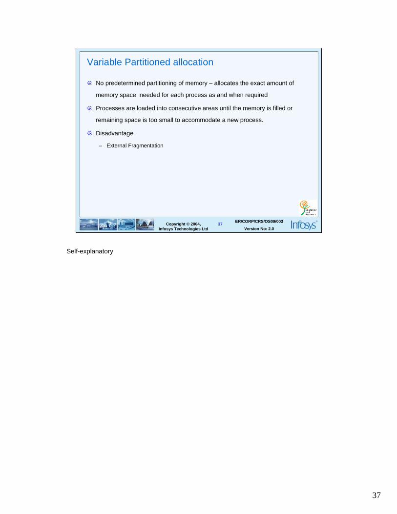
No predetermined partitioning of memory – allocates the exact amount of
memory space needed for each process as and when required
Processes are loaded into consecutive areas until the memory is filled or
remaining space is too small to accommodate a new process.
Disadvantage
– External Fragmentation
Self-explanatory
38
38ER/CORP/CRS/OS09/003
Version No: 2.0Copyright © 2004,
Infosys Technologies Ltd
Variable Partitioned Allocation
JOB 1
JOB 2
JOB 3
FREE
MEMORY MEMORY
FREE
JOB 2
FREE
FREE
OS
20 K
10 K
30 K
10 K
(A) (B)
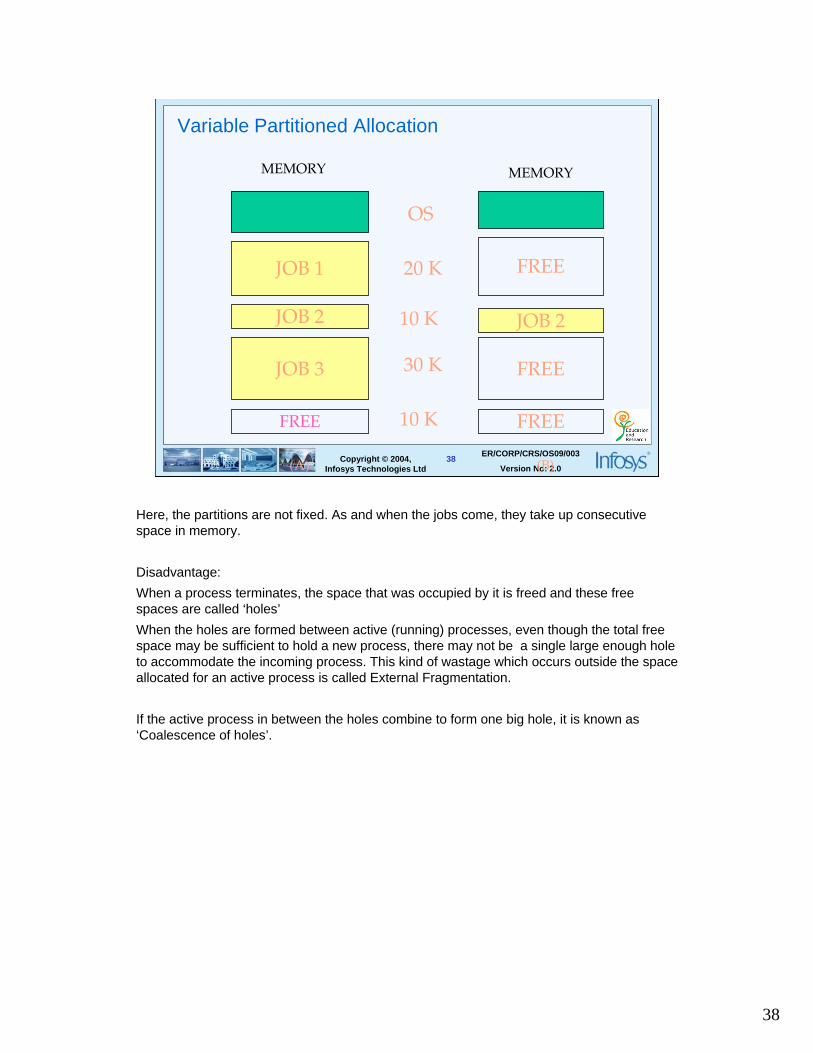
Here, the partitions are not fixed. As and when the jobs come, they take up consecutive space in memory.
Disadvantage:
When a process terminates, the space that was occupied by it is freed and these free spaces are called ‘holes’
When the holes are formed between active (running) processes, even though the total free space may be sufficient to hold a new process, there may not be a single large enough holeto accommodate the incoming process. This kind of wastage which occurs outside the space allocated for an active process is called External Fragmentation.
If the active process in between the holes combine to form one big hole, it is known as ‘Coalescence of holes’.

39
39ER/CORP/CRS/OS09/003
Version No: 2.0Copyright © 2004,
Infosys Technologies Ltd
Relocatable Partitioned Allocation
Space wasted due to fragmentation can be used by doing compaction –
running jobs are squeezed together by relocating them and clubbing the rest of
the free space into one large block.
Simple to implement
In this mode, the active process shifts to one end, leaving the holes to combine to get a much larger space than before.

40
40ER/CORP/CRS/OS09/003
Version No: 2.0Copyright © 2004,
Infosys Technologies Ltd
Relocatable partitioned allocation
OS
20 K
10 K
30 K
10 K
MEMORY
FREE
JOB 2
FREE
FREE
MEMORY
FREE
JOB 2
FREE
FREE
After Compaction
The diagram above shows that JOB2 has been moved upward leaving 50 K of contiguous free space. A new job of 50 K can be run now.
Disadvantage:
•Relocating the running jobs afresh leads to problems that are address dependent
Solution:
•Reload & start from beginning every programs that needs to be relocated which is very expensive and at times is an irreversible action
•Relative addressing mechanism wherein the job is run independent of any program location. The disadvantage of Relative Addressing is that an extra overhead would be incurred because of a separate index register and addressing through the index registers.

41
41ER/CORP/CRS/OS09/003
Version No: 2.0Copyright © 2004,
Infosys Technologies Ltd
Simple paged allocation
Divides the jobs address space into pages of the same size(4K)
Divides the main memory address space into blocks/frames(4 K)
Pages are units of memory that are swapped in and out of primary memory
Pages are grouped together for a given user job and are placed in page tables
Simple paged allocation is a solution to fragmentation.
Advantage:
As each page is separately allocated, the users job need not be contiguous.
Disadvantages:
•Extra memory required for storing page tables
•Considerable amount of hardware support is required for address transformations etc.
•All pages of entire job must be in memory
42
42ER/CORP/CRS/OS09/003
Version No: 2.0Copyright © 2004,
Infosys Technologies Ltd
Simple paged allocation
1000 2000 3000 4000
7000
0 21 42
7
0 3
JOB 1
JOB 2
page number block numberOS
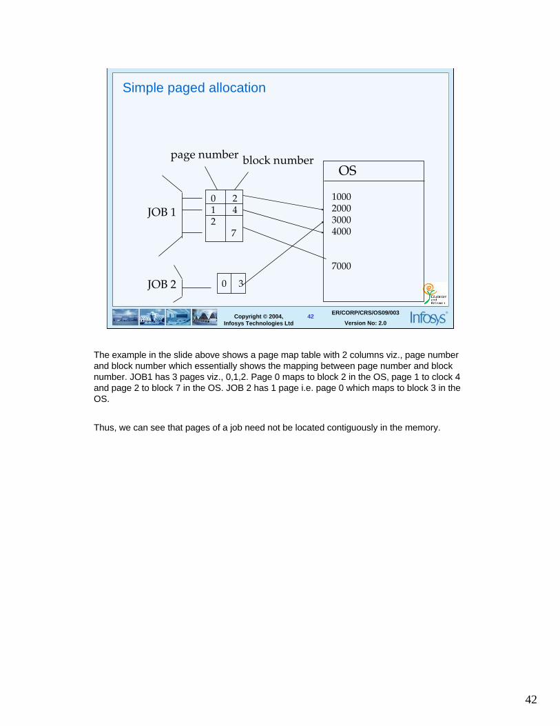
The example in the slide above shows a page map table with 2 columns viz., page number and block number which essentially shows the mapping between page number and block number. JOB1 has 3 pages viz., 0,1,2. Page 0 maps to block 2 in the OS, page 1 to clock 4 and page 2 to block 7 in the OS. JOB 2 has 1 page i.e. page 0 which maps to block 3 in the OS.
Thus, we can see that pages of a job need not be located contiguously in the memory.
43
43ER/CORP/CRS/OS09/003
Version No: 2.0Copyright © 2004,
Infosys Technologies Ltd
Demand paging
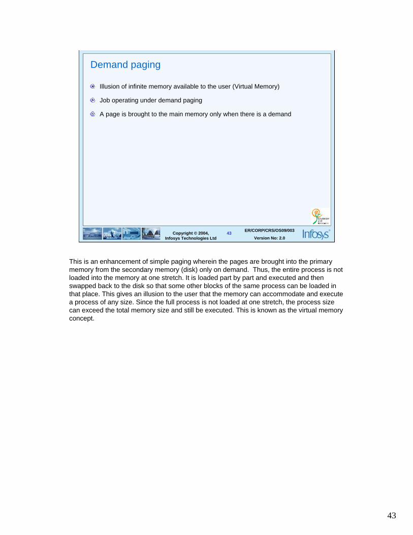
Illusion of infinite memory available to the user (Virtual Memory)
Job operating under demand paging
A page is brought to the main memory only when there is a demand
This is an enhancement of simple paging wherein the pages are brought into the primary memory from the secondary memory (disk) only on demand. Thus, the entire process is not loaded into the memory at one stretch. It is loaded part by part and executed and then swapped back to the disk so that some other blocks of the same process can be loaded in that place. This gives an illusion to the user that the memory can accommodate and execute a process of any size. Since the full process is not loaded at one stretch, the process size can exceed the total memory size and still be executed. This is known as the virtual memoryconcept.

44
44ER/CORP/CRS/OS09/003
Version No: 2.0Copyright © 2004,
Infosys Technologies Ltd
Demand paging
Page number Block numberPage Table
JOB 12 3 A 1
Status Judgement
1000 2000 3000 4000
7000
OS OS
The diagram in the slide above shows the page map table for demand paging. The page map table (PMT) has two additional columns viz., status and judgement. Initially, all the pages have status field as NA (Not Available) implying that all the pages are in the secondary device (disk). As and when a page is loaded from the secondary to primary, the status is updated to A (Available) from NA. Now, if the same page is required again in the main memory, the status bit will indicate the presence of it in the primary memory. The judgement field decides if a page has to be moved back to the secondary memory or not.

45
45ER/CORP/CRS/OS09/003
Version No: 2.0Copyright © 2004,
Infosys Technologies Ltd
Page replacement algorithms
Algorithms based on which the pages are selected for replacement
Examples
– Least Frequently Used (LFU)
– Least Recently Used ( LRU )
– Not Recently Used (NRU )
– First in First out (FIFO )
LFU: If the algorithm decides to move a page from main memory and store it in secondary memory based on the fact that it is not used often, then it is called LFU. For every page a reference counter is maintained in the judgement field.
LRU: If the algorithm decides to move a page from main memory and store it in secondary memory based on the fact that it is not used often in the recent times, then it is called LRU. For every page a timestamp is maintained in the judgement field.
NRU: If the algorithm decides to move a page from main memory and store it in secondary memory based on the fact that it is not used at all in the recent times, then it is called NRU. A reference bit is associated with each page.
FIFO: If the algorithm decides that the page has been first moved to the memory should be moved out to secondary memory first, then it is using FIFO.

46
46ER/CORP/CRS/OS09/003
Version No: 2.0Copyright © 2004,
Infosys Technologies Ltd
Thrashing
Most of the time is being spent in either swapping in or swapping out of the
pages from main memory to secondary memory,instead of doing useful work
This high paging activity when happens frequently is called THRASHING
To overcome thrashing ,system schedules some pages to be removed from
memory in the background (Page Stealing) and continues till a certain level of
page frames are free
Page Fault: If a user job accesses a page and the page is not available in the main memory, a page fault is said to occur
Page Replacement: If the memory is full then the inactive pages which are not needed currently for execution are removed and are replaced by those pages from the secondary device which are to be executed. This is called Page Replacement.

47
47ER/CORP/CRS/OS09/003
Version No: 2.0Copyright © 2004,
Infosys Technologies Ltd
Segmentation
Segment is a grouping of information that is treated as a logical entity
A process is divided into different segments each of its own length for example
one segment can correspond to a single subroutine, a group of closely related
subroutines etc.
Segmentation uses unequal chunks
Chunk size is determined by the programmer
Each individual segment can be protected
Requires two-level translation : Segment tables to page tables and then to
main memory
Paging brought about a separation between the user’s view of memory and the actual physical memory which is taken care of in segmentation.
The user prefers to view memory as a collection of different sized segments with no necessary ordering among the segments. Say for example, when a user writes a program, he thinks about is a main program with a set of subroutines, procedures, functions etc. Each of these modules are referred to by a name and each of these segments are of variable length. The length of a segment is defined by the purpose of the segment in the program.
Segmentation is thus a memory management technique which supports the user view of memory. A programmer has a say on the number of segments in a process and this division is dependent on the logical structure of the process.

48
48ER/CORP/CRS/OS09/003
Version No: 2.0Copyright © 2004,
Infosys Technologies Ltd
Summary
System Software
Translators
Operating System
Memory Management

49
49ER/CORP/CRS/OS09/003
Version No: 2.0Copyright © 2004,
Infosys Technologies Ltd
Thank You!