computer aided feeding system design for pressure...
TRANSCRIPT

COMPUTER AIDED FEEDING SYSTEM DESIGN
FOR PRESSURE DIECASTING
Dissertation submitted in the partial fulfillment of the
requirements for the degree of
Master of Technology
In
Mechanical Engineering
Submitted by
Deepak Tanksale
(98310407)
Guide
Prof B Ravi
Department of Mechanical Engineering
IIT Bombay
Mumbai
December 1999

DISSERTATION APPROVAL SHEET
This dissertation entitled “ Computer Aided Feeding system Design for Pressure
Diecasting”, by Deepak Tanksale is approved for the degree of Master of Technology
Guide Chairman External Examiner Internal Examiner

ABSTRACT
An important factor for obtaining defect free pressure diecast parts is good design
of the feeding system. Feeding system is a path of flow of molten alloy during
filling of casting. In this project a systematic approach has been developed to
design feeding system for pressure diecasting die. This involved studying current
design practices in the industry and translating this into a knowledge base of
rules for machine selection, design of gate, gaterunner, runner, overflows and
airvents. The designed feeding system is evaluated in terms of criteria such as
filling, air entrapment, power utilization, yield, and fettling. The entire approach
has been implemented in a windows based program using visual C++.
It has been successfully tested on industrial case study. It is perhaps the
first attempt of its kind in the area of pressure diecasting die design, and is
expected to be of significant interest and value to the industry.
INDEX
CHAPTER CONTENTS PAGE
1 INTRODUCTION 1
1 1 Die Design 2
1 1 1 Analysis Stage 2
1 1 2 Design Stage 4
1 2 Feeding System 4
2 LITERATURE REVIEW 8
2 1 Theory of Cavity Filling 10
2 2 Planning Flow Path 12
2 2 1 Rectangular Castings 17
2 2 2 Round Castings 17
2 2 3 Pipe Shaped Castings 19
2 3 Cavity Fill Time 21
2 4 Gate 22
2 4 1 Gate Velocity 22
2 4 2 Gate Area 22
2 4 3 Gate Thickness 23
2 4 4 Gate Width 24
2 5 Runner 24
2 6 Overflows 26
2 7 Airvents 26
2 8 Flow Simulation 27
2 9 Machine Selection 28
2 10 Summary of Literature Review 30
3 PROBLEM DEFINITION 32
3 1 Motivation 32
3 2 Objectives & Scope 32
3 3 Approach 33
4 SYSTEM DESIGN 34
4 1 Database 34

CHAPTER CONTENTS PAGE
4 1 1Product 34
4 1 2Material 34
4 1 3Machine 37
4 2 Feed system 37
4 2 1Factors 37
4 2 2Flow design 37
4 2 3Feed design 40
4 2 4Layout 43
4 2 5Analysis 43
4 3 Data Structure 43
4 4 Menu design 45
5 RESULTS 46
5 1 Session 46
5 2 Validation 46
5 3 Case Studies 46
5 1 1 Endshield 47
5 1 2 Terminal Box 55
6 CONCLUSIONS 63
6 1 Conclusions 63
6 2 Future Work 64
7 REFERENCES 65
APPENDIX 1 67
APPENDIX 2 69
APPENDIX 3 72
APPENDIX 4 73
APPENDIX 5 74
APPENDIX 6 75

LIST OF FIGURES
FIGURE CONTENTS PAGE
1 Pressure Diecasting Die 3
2 The Principal Parts of the Feeding System 6
3 Cavity Filling Pattern 9
4 Fishtail Runner 11
5 The Fan Gate Runner 11
6 The Tangential Gate Runner 13
7 Flow Angle for Tangential Runner 13
8 Feed Systems for Rectangular Castings 15
9 Feed Systems for Round Castings 16
10 Ideal Flow Path in Round and Deep Castings 18
11 Ring Type Gating for Tubular Castings 18
12 Gating for Deep Cavity 20
13 Runner Details 20
14 Blind Runner 25
15 Overflows 25
16 Die Opening Force ( without cores ) 29
17 Die Opening Force ( with cores ) 29
18 System Design 35
19 Flow Chart for Flow Design Module 36
20 Flow Chart for Gate & Gaterunner Module 38
21 Flow Chart for Runner & Venting Module 39
22 Flow Chart for Machine Settings & Result Module 41
23 Flow Chart for Analysis Module 42
24 Data Structure 44
25 Endshield 47
26 Database for Endshield 48
27 Flow design for Endshield 49
28 Feed design for Endshield 50
29 Layout for Endshield 52
30 Analysis for Endshield 53

FIGURE CONTENTS PAGE
31 Terminal Box 55
32 Database for Terminal Box 56
33 Flow design for Terminal Box 57
34 Feed design for Terminal Box 58
35 Layout for Terminal Box 60
36 Analysis for Terminal Box 61

LIST OF TABLES
TABLE CONTENTS PAGE
1 Variables for cavity filling time calculations 67
2 Recommended values for gate velocity 67
3 Recommended values for gate thickness 67
4 Recommended values of specific casting pressure 67
5 List of softwares and their capabilities 68
1 INTRODUCTION
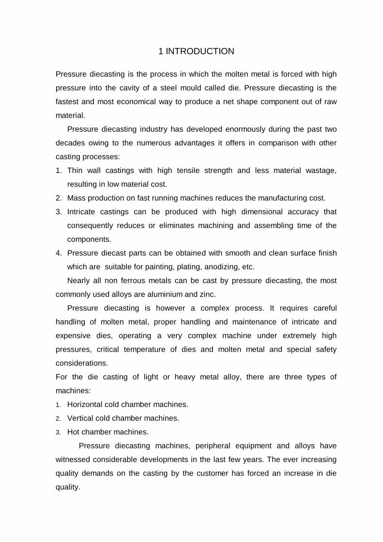
Pressure diecasting is the process in which the molten metal is forced with high
pressure into the cavity of a steel mould called die. Pressure diecasting is the
fastest and most economical way to produce a net shape component out of raw
material.
Pressure diecasting industry has developed enormously during the past two
decades owing to the numerous advantages it offers in comparison with other
casting processes:
1. Thin wall castings with high tensile strength and less material wastage,
resulting in low material cost.
2. Mass production on fast running machines reduces the manufacturing cost.
3. Intricate castings can be produced with high dimensional accuracy that
consequently reduces or eliminates machining and assembling time of the
components.
4. Pressure diecast parts can be obtained with smooth and clean surface finish
which are suitable for painting, plating, anodizing, etc.
Nearly all non ferrous metals can be cast by pressure diecasting, the most
commonly used alloys are aluminium and zinc.
Pressure diecasting is however a complex process. It requires careful
handling of molten metal, proper handling and maintenance of intricate and
expensive dies, operating a very complex machine under extremely high
pressures, critical temperature of dies and molten metal and special safety
considerations.
For the die casting of light or heavy metal alloy, there are three types of
machines:
1. Horizontal cold chamber machines.
2. Vertical cold chamber machines.
3. Hot chamber machines.
Pressure diecasting machines, peripheral equipment and alloys have
witnessed considerable developments in the last few years. The ever increasing
quality demands on the casting by the customer has forced an increase in die
quality.
The Pressure diecasting die has four basic functions as follows :
1. Accommodate the molten metal to form in the shape of desired casting.
2. Provide the means for the molten metal to get into the space where it is to be
held in the desired shape.
3. Remove heat from the molten metal to solidify the metal.
4. Provide for the removal of solidified casting.
The most obvious feature of a diecasting die is that it consists of two die blocks
that close against each other. All the components and features of the die are
machined into those blocks. Die design is discussed in the next section.
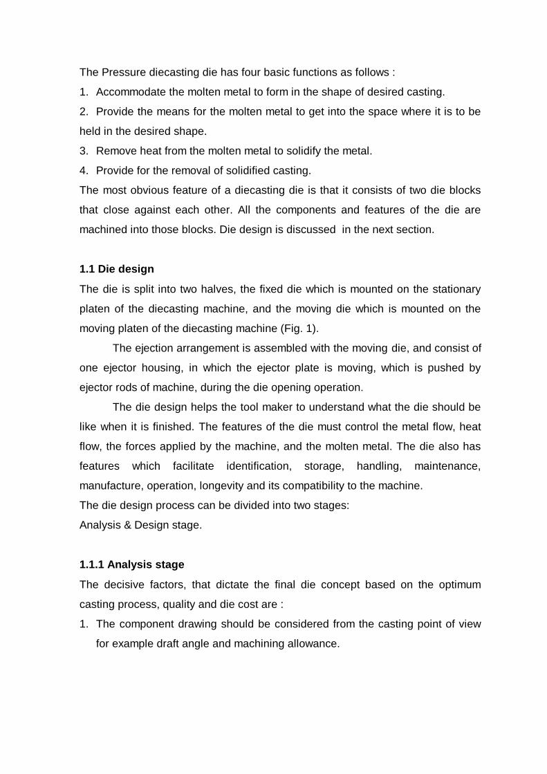
1.1 Die design
The die is split into two halves, the fixed die which is mounted on the stationary
platen of the diecasting machine, and the moving die which is mounted on the
moving platen of the diecasting machine (Fig. 1).
The ejection arrangement is assembled with the moving die, and consist of
one ejector housing, in which the ejector plate is moving, which is pushed by
ejector rods of machine, during the die opening operation.
The die design helps the tool maker to understand what the die should be
like when it is finished. The features of the die must control the metal flow, heat
flow, the forces applied by the machine, and the molten metal. The die also has
features which facilitate identification, storage, handling, maintenance,
manufacture, operation, longevity and its compatibility to the machine.
The die design process can be divided into two stages:
Analysis & Design stage.
1.1.1 Analysis stage
The decisive factors, that dictate the final die concept based on the optimum
casting process, quality and die cost are :
1. The component drawing should be considered from the casting point of view
for example draft angle and machining allowance.

2. Possible and achievable tolerances should be discussed between the
customer and the die maker. Avoid unnecessary close tolerances limits, as it will
mean a cost increase and frequently a low production rate.
3. Select the most suitable diecasting alloy for the proposed component,
considering the physical properties, cost, and availability.
4. Establish the required monthly or yearly production which will greatly influence
the decision of the proposed number of die cavities.
5. Considerations for fast tool loading and unloading on diecasting machine.
It is always advisable to consider the opinion and the requirements of the
customer, marketing expert, diecasting engineer, diemaker during the die design
phase.
Analysis stage can further be divided into following:
1. Feeding system analysis.
2. Thermal system analysis.
3. Dimensional analysis
4. Force calculations.
1.1.2 Design stage
After the die designer has established all the requirements regarding production
quantities, various allowances on casting, required pressure diecasting machine
based on analysis stages, the actual die design work can be started. The die
designer’s objective is to design dies which will give sound casting, operate at
optimum shot rate, and be of reasonably simple construction.
Design stage consists of:
1. Casting to die orientation.
2. Parting line geometry.
3. Feeding system design.
4. Thermal system design.
5. Mechanical constructions within the cavity blocks.
6. Cavity blocks and alignment systems.
7. Material selection for various parts in die.

In the following section pressure diecasting feeding system is discussed.
1.2 Feeding system
The feeding system of a diecasting die consists of a series of passages through
which the molten metal can flow into the die and then through the interior of the
die to fill the cavity. The molten metal is pushed into the feeding system from
outside the die by a plunger.
The cold chamber diecasting machine usually has that plunger mounted
horizontally in a thick tube called the shot sleeve. The plunger pushes the molten
metal directly into the parting surfaces of the die. Any excess metal remains in the
end of shot sleeve between the plunger and the parting surface of the ejector die
half is called the biscuit. The biscuit and other parts of the feeding system solidify
as integral parts of the casting and are removed from the die with the casting.
Once the molten metal reaches the parting surface of the die it is
conducted towards the cavity through channels called runners. The runners are
usually trapezoidal in cross section. There may be more than one runner
radiating from the biscuit, and any one runner may split into two or more as
required to direct the molten metal to various places. As the runner approaches
the cavity it blends from trapezoidal shape into a slit like opening into the cavity.
The blended portion is called the gaterunner and the slit like opening into the
cavity is called the gate. It is usually necessary to allow the gases in the cavity to
be pushed out by in rushing molten metal and to allow some of the molten metal
to flow through and on out of the cavity. Such a flow through action flushes out
the undesirable materials so only proper metal remains in the cavity. To facilitate
the flushing action, chambers called overflows are provided outside of the cavity
opposite the gate. These features make up the feeding system. In addition to this
thin spaces called vents can be provided between the mating die halves that form
channels from the overflow or cavity to the outside of the die. These vents allow
gases to escape, but are so thin that the metal being cast freezes before reaching
the edge of the die (Fig. 2).
The basic function of the feeding system is to provide a system of
passageways for the molten metal to flow through to get into the cavity. Once in

the cavity, the metal will solidify into the desired casting. Objective of feeding
system analysis is to achieve constant cavity fill time. The cavity fill time is
influenced in the first place by the optimum setting of the die casting machine’s
shot end parameters and by the size, shape and position of various components
of the feeding system.
The volume of the casting must be determined before any of the gating
calculations are made. The volume must also be known for the cost estimation
and the heat flow analysis. But before the volume is computed the first step is to
analyze the component and determine where it should be gated, to provide the
quality and finish dimensional stability.
The next chapter of literature survey details about study carried out for diecasting
die design practices.

2 LITERATURE REVIEW
In this chapter, a detailed study of diecasting die design practices is included,
based on both literature and industry sources.
Feed system is a path, through which the molten metal is forced into
cavity. The configuration and dimensioning of feed system must be so that the
flow is with least resistance and without whirling. There is a wide range of
literature and papers about investigation and research work on this subject from
various scientists and experts, the mention of which is made in the references.
The position, size and shape of the feed system components are the most
important factors to obtain a casting of high quality, particularly in respect of
surface finish and structural soundness. Since the castings differ widely in size
and shape, the feed system design has to be done on case to case basis.
Till now, no equation has been developed successfully, on which basis the
size of feed system design can be decided. Years of experience and records of
past performance have been the basis in the development of certain rules which
are till date generally followed. However, it is quite common that for intricate
component designs, more than one of the rules mentioned hereunder might be
applicable, which are often contradictory.
Considering this fact, it is essential for the die designer to keep all possible
difficulties in mind which may occur, and decide on a design with the possibility
to alter later if so required. Following points should be followed for designing feed
system [1].
1. Preferably only one gate should be provided. In case of more gates, care
should be taken that the individual metal streams entering the cavity do not
interfere.
2. The cavity should be filled from one direction to another, to avoid incoming
stream getting divides into several jets.
3. It is preferable, specially on large castings, to provide the gating point on
casting periphery, which will shorten the distance, the metal has to travel
through the cavity.
4. Care should be taken while deciding the place and direction of gates, so that
no air pockets can develop during the filling period.
5. On a correct directed gate, the metal entering the cavity should push the air to
the air vents.
6. On thin walled castings the best surface finish can be obtained generally with
thin gate and high injection speed.
7. On thick walled components, sound and pressure tight castings can be
obtained only with thick gate, slow injection speed, but high pressure.
8. The metal stream should fill the cavity with the least possible obstruction, i.e.
direct hitting on cores should be avoided as far as possible. The gate location
should be so arranged that easy breaking of gate is ensured without breaking
corners of casting. At the same time they should be on places where no extra
machining will be necessary to remove the marks.
Theory of cavity filling helps to understand feeding in diecasting die.
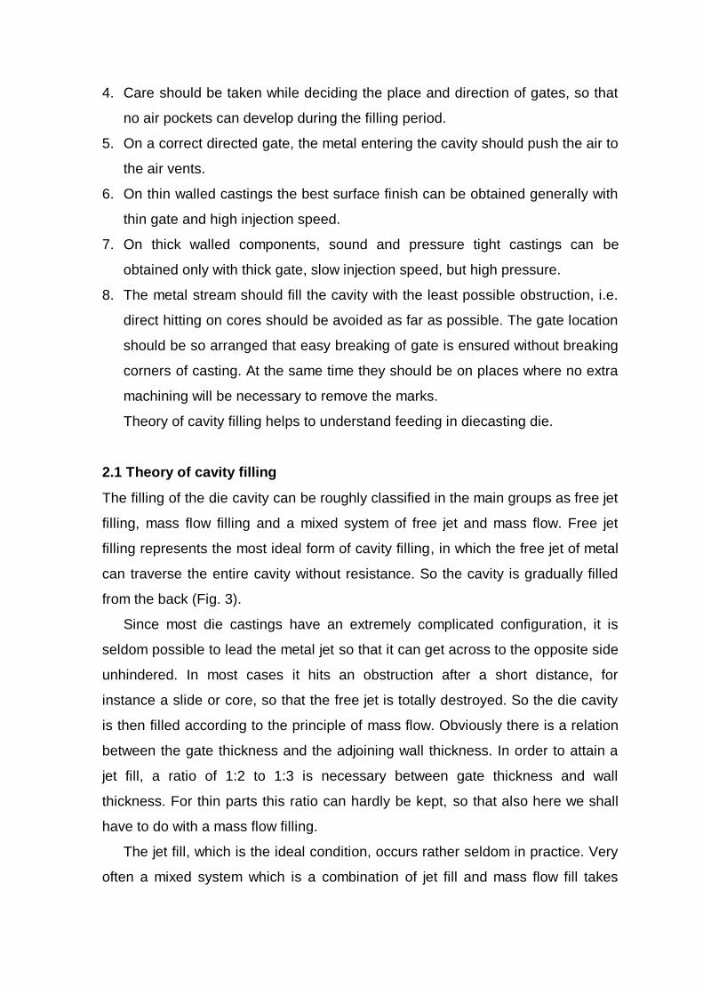
2.1 Theory of cavity filling
The filling of the die cavity can be roughly classified in the main groups as free jet
filling, mass flow filling and a mixed system of free jet and mass flow. Free jet
filling represents the most ideal form of cavity filling, in which the free jet of metal
can traverse the entire cavity without resistance. So the cavity is gradually filled
from the back (Fig. 3).
Since most die castings have an extremely complicated configuration, it is
seldom possible to lead the metal jet so that it can get across to the opposite side
unhindered. In most cases it hits an obstruction after a short distance, for
instance a slide or core, so that the free jet is totally destroyed. So the die cavity
is then filled according to the principle of mass flow. Obviously there is a relation
between the gate thickness and the adjoining wall thickness. In order to attain a
jet fill, a ratio of 1:2 to 1:3 is necessary between gate thickness and wall
thickness. For thin parts this ratio can hardly be kept, so that also here we shall
have to do with a mass flow filling.
The jet fill, which is the ideal condition, occurs rather seldom in practice. Very
often a mixed system which is a combination of jet fill and mass flow fill takes
place. In order to have better control over the mass flow fill most experienced
diecasters tend to lead the metal flow into a corner so that the filling of the cavity
remains clearly under control [2].
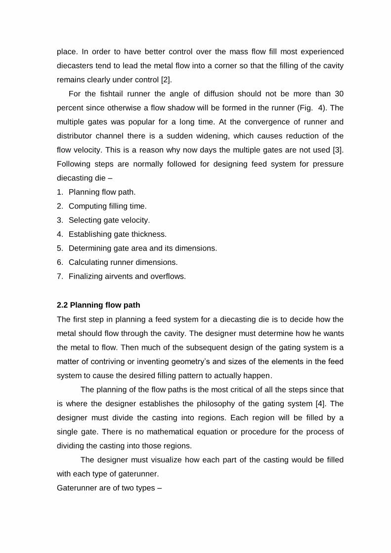
For the fishtail runner the angle of diffusion should not be more than 30
percent since otherwise a flow shadow will be formed in the runner (Fig. 4). The
multiple gates was popular for a long time. At the convergence of runner and
distributor channel there is a sudden widening, which causes reduction of the
flow velocity. This is a reason why now days the multiple gates are not used [3].
Following steps are normally followed for designing feed system for pressure
diecasting die –
1. Planning flow path.
2. Computing filling time.
3. Selecting gate velocity.
4. Establishing gate thickness.
5. Determining gate area and its dimensions.
6. Calculating runner dimensions.
7. Finalizing airvents and overflows.
2.2 Planning flow path
The first step in planning a feed system for a diecasting die is to decide how the
metal should flow through the cavity. The designer must determine how he wants
the metal to flow. Then much of the subsequent design of the gating system is a
matter of contriving or inventing geometry’s and sizes of the elements in the feed
system to cause the desired filling pattern to actually happen.
The planning of the flow paths is the most critical of all the steps since that
is where the designer establishes the philosophy of the gating system [4]. The
designer must divide the casting into regions. Each region will be filled by a
single gate. There is no mathematical equation or procedure for the process of
dividing the casting into those regions.
The designer must visualize how each part of the casting would be filled
with each type of gaterunner.
Gaterunner are of two types –

1. Fan type.
2. The tangential type.
Both the fan and tangential gate runners match the runner where they connect
to it. The fan gate runner becomes thinner and wider as it gets closer to the cavity
until it is as wide as the gate is long and as deep as the gate. Usually the depth is
changed proportionally with distance, but that is not a requirement. Sometimes it
is desirable to have the sides of the fan gate runner be straight lines in the plan
view and the depth adjusted to get the cross sectional areas required. Because of
the shape of the fan gate runner the molten metal flow is spread out such that the
flow streams are diverging as they enter the cavity as indicated by the arrows
(Fig. 5). The flow is not in parallel streams and the flow is not perpendicular to the
edge of the cavity. Both of these conditions (i.e. parallelism and perpendicularity)
were assumed above for ideal flow patterns.
The tangential gate runner carries the flow of molten metal along the edge of
the cavity as shown by the arrows (Fig. 6). As the metal travels along the edge of
the cavity it passes sideways through the gate into the cavity. The result is the
metal can be made to enter the cavity in parallel flow streams, but those flow
streams will not be perpendicular to the edge of the cavity. Because the flow of
the molten metal entering the cavity is not perpendicular to the edge of the cavity,
and in some instances will not even be in parallel flow streams, a gate does not
necessarily fill that part of the cavity that is straight across from the gate [5].
There is nothing bad about such behavior, but it must be recognized by the
designer and manipulated to his advantage.
The angle between the actual flow direction and a line perpendicular to the
edge of the cavity is the flow angle (Fig. 7). In general flow angles between 30
and 40 degrees work out best. Smaller flow angles result in large runners and
flow angles over 45 degrees may not even be possible.
If some portion of a casting approximates the shape of a parallelogram it can
probably be filled best with a tangential gate runner, and if the region of the
casting is shaped more like a trapezoid then a fan gate runner is likely to be best.
Usually tangential and fan gate runners are used in combination. A fan gate
runner is positioned to feed the center part of the casting and a tangential gate

runner is placed along each end. The center of casting is arbitrarily defined as a
trapezoid and the two ends as parallelograms.
Although each casting component has got its own shape, certain
characteristic forms can be found on most parts. Some of the most common forms
with its best suitable gating are explained as following:
2.2.1 Rectangular casting
Most of the industrial components are more or less classified into rectangular
shape [6]. We will analysis eight different shapes and gating layout for same
casting (Fig. 8). In the example A and B, the metal flows initially in the runner to
one end, from where it fills the cavity. The gating in this case is indirect, but will
work satisfactorily. The main disadvantage is, that the metal temperature will
have to be increased in order to maintain the required casting temperature by the
time it reaches the other end of the cavity. This can be improved to a certain
extent if big dimensioned overflows are provided on the opposite gating side, to
increase the die temperature on that area.
The example C will have the same problem as A and B with respect of the
temperature. One advantage however will be, that the metal enters the cavity
parallel to the main axis of the casting and might therefore develop less whirls
and turbulence. The examples D and E are likewise A and B gated from one end,
but with the filling direction of the cavity. For a casting with thicker section the
variation E should be given preference, since the metal will flow more turbulence
free and slower, this gives air a better chance to escape.
For thin walled castings where thinner and longer gating and quick filling
give better surface finish, the variation D is more desirable. F, G and H show the
gating from the middle of the casting. Both F and H are not favorable as on F the
metal flows first to both ends and meets last in the center. Trapped air and flow
marks cannot be avoided. Overflows as shown are absolutely necessary. The
disadvantage of the gating type H is same as that of F. The gating example G will
give about the same performance as type E, and is preferably used when the
rectangular casting is very long. However the best selection of the gating
explained above for castings are D, E or G.
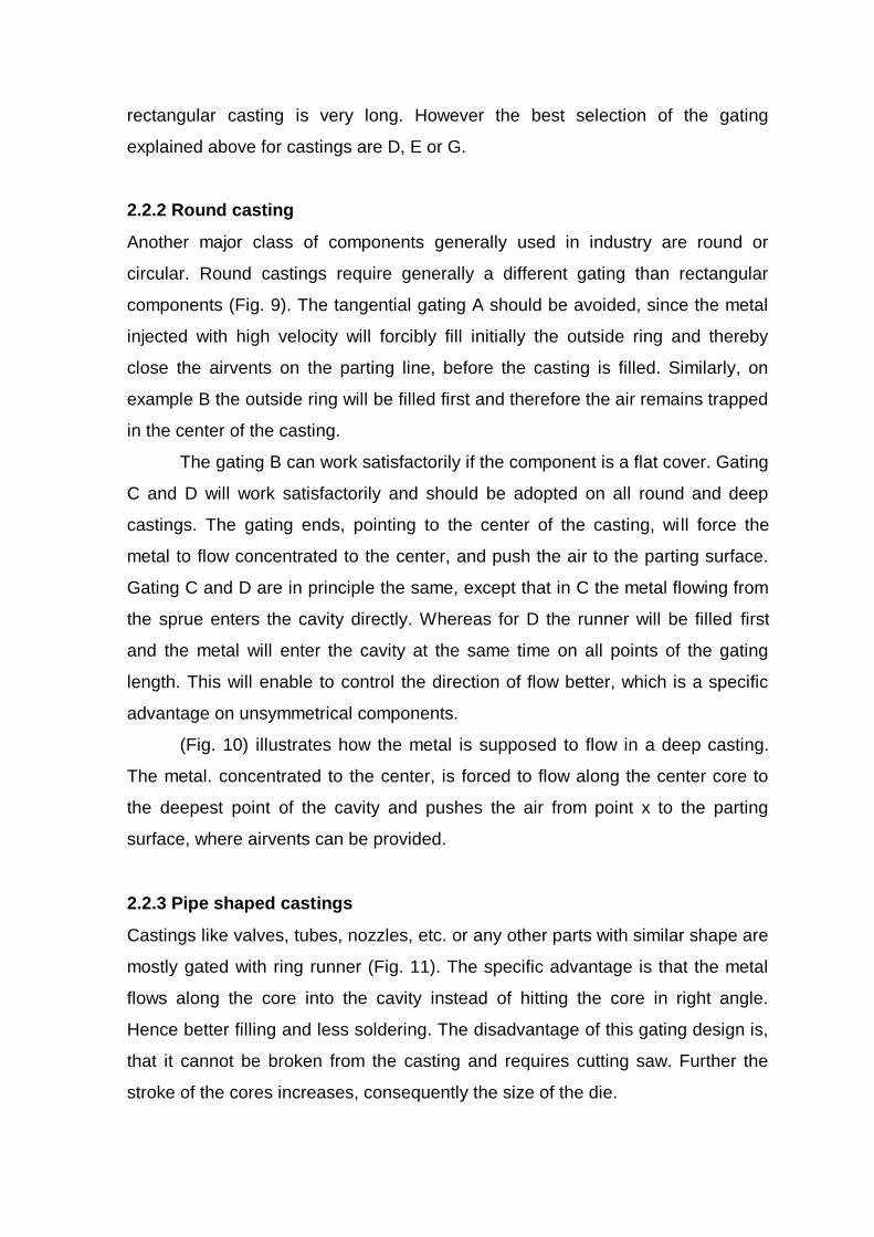
2.2.2 Round casting
Another major class of components generally used in industry are round or
circular. Round castings require generally a different gating than rectangular
components (Fig. 9). The tangential gating A should be avoided, since the metal
injected with high velocity will forcibly fill initially the outside ring and thereby
close the airvents on the parting line, before the casting is filled. Similarly, on
example B the outside ring will be filled first and therefore the air remains trapped
in the center of the casting.
The gating B can work satisfactorily if the component is a flat cover. Gating
C and D will work satisfactorily and should be adopted on all round and deep
castings. The gating ends, pointing to the center of the casting, will force the
metal to flow concentrated to the center, and push the air to the parting surface.
Gating C and D are in principle the same, except that in C the metal flowing from
the sprue enters the cavity directly. Whereas for D the runner will be filled first
and the metal will enter the cavity at the same time on all points of the gating
length. This will enable to control the direction of flow better, which is a specific
advantage on unsymmetrical components.
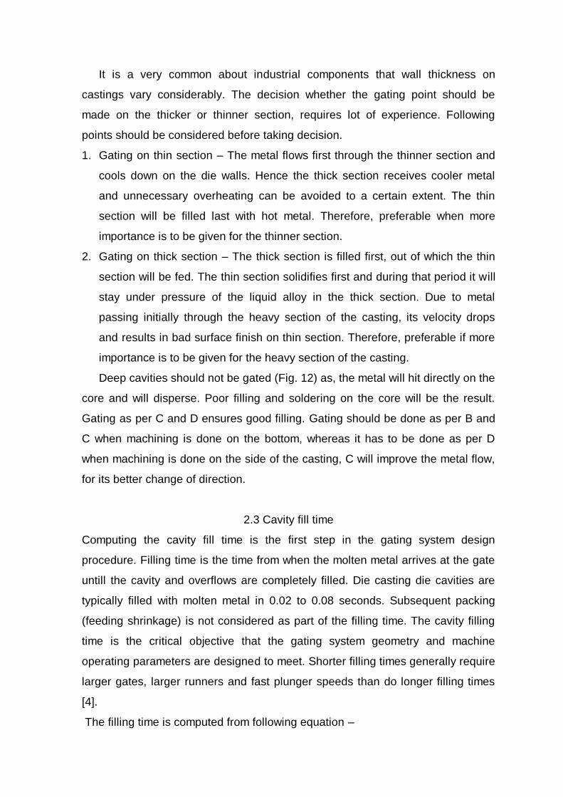
(Fig. 10) illustrates how the metal is supposed to flow in a deep casting.
The metal. concentrated to the center, is forced to flow along the center core to
the deepest point of the cavity and pushes the air from point x to the parting
surface, where airvents can be provided.
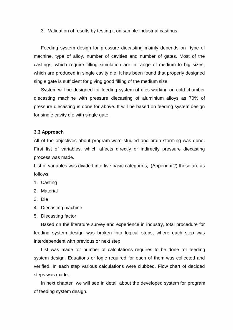
2.2.3 Pipe shaped castings
Castings like valves, tubes, nozzles, etc. or any other parts with similar shape are
mostly gated with ring runner (Fig. 11). The specific advantage is that the metal
flows along the core into the cavity instead of hitting the core in right angle.
Hence better filling and less soldering. The disadvantage of this gating design is,
that it cannot be broken from the casting and requires cutting saw. Further the
stroke of the cores increases, consequently the size of the die.
It is a very common about industrial components that wall thickness on
castings vary considerably. The decision whether the gating point should be
made on the thicker or thinner section, requires lot of experience. Following
points should be considered before taking decision.
1. Gating on thin section – The metal flows first through the thinner section and
cools down on the die walls. Hence the thick section receives cooler metal
and unnecessary overheating can be avoided to a certain extent. The thin
section will be filled last with hot metal. Therefore, preferable when more
importance is to be given for the thinner section.
2. Gating on thick section – The thick section is filled first, out of which the thin
section will be fed. The thin section solidifies first and during that period it will
stay under pressure of the liquid alloy in the thick section. Due to metal
passing initially through the heavy section of the casting, its velocity drops
and results in bad surface finish on thin section. Therefore, preferable if more
importance is to be given for the heavy section of the casting.
Deep cavities should not be gated (Fig. 12) as, the metal will hit directly on the
core and will disperse. Poor filling and soldering on the core will be the result.
Gating as per C and D ensures good filling. Gating should be done as per B and
C when machining is done on the bottom, whereas it has to be done as per D
when machining is done on the side of the casting, C will improve the metal flow,
for its better change of direction.
2.3 Cavity fill time
Computing the cavity fill time is the first step in the gating system design
procedure. Filling time is the time from when the molten metal arrives at the gate
untill the cavity and overflows are completely filled. Die casting die cavities are
typically filled with molten metal in 0.02 to 0.08 seconds. Subsequent packing
(feeding shrinkage) is not considered as part of the filling time. The cavity filling
time is the critical objective that the gating system geometry and machine
operating parameters are designed to meet. Shorter filling times generally require
larger gates, larger runners and fast plunger speeds than do longer filling times
[4].
The filling time is computed from following equation –

t = k * T * ( Ti – Tf + SZ ) / ( Tf – Td )
where : t = cavity filling time sec
K = empirically derived constant (sec / mm)
T = casting thickness (mm)
Ti = temperature of molten metal as it enters the die (deg C)
Tf = Minimum flow temperature (deg C)
Td = Temperature of die cavity surface (deg C)
S = percent solid fraction allowable in the metal at the end of filling
Z = units conversion factor (C deg. / %)
Typical values for k, Ti, Tf, Td and Z are given in Table1 refer Appendix 1.
The sizes of the gates and runners will be based on the calculated ideal
cavity filling time. The above equation shows that if the die is operated differently,
it should have a different filling time. So, once the die is built with gates and
runners sized for a specific filling time ( and machine power availability), it must
be operated at the conditions to which the cavity filling time was calculated. It is
critically important that the holding furnace temperature and die temperature
assumed for the gating equation be communicated to the operator of the die
casting machine. If the die is operated with different conditions for the critical
variables, the gating system will not perform correctly. These temperatures and
the percent solids factor, S are also critical to the die design. The thermal control
features are designed into the die to accommodate the exact resulting heat input.
2.4 Gate
Gate is the opening through which molten metal enters the cavity. It is most
important component of feed system design. The dimensions of gate (gate
thickness and gate width), gate position and gate velocity are most critical
variables from filling point of view of casting. As improper design of any of them
can result in failure of die [7].
2.4.1 Gate velocity
The gate velocity is the speed at which the molten metal moves through the
gate. It is of crucial essence that the cavity filling takes place with a flow

into the cavity, free of whirling. In order to avoid discontinuity, the flow
velocity of the metal in the runners must be constant or slightly accelerated
up to gate [8]. The velocity of molten alloy through the gate depends on -
1. The energy of the machine.
2. The pressure losses in the total flow system, including the gate.
3. The type of runner and gate.
Because of the multitude and variety of castings in their form, use and
required alloys, the values for gate velocity can be taken only from such tables as
have been set up from individual experience or from those that have been
published.
Recommendations for gate velocities are given in Table 2 refer Appendix 1.
2.4.2 Gate area
Gate area is always used to mean the cross sectional area through which the
molten metal must flow as it passes through the gate. Gate area is calculated
based on casting volume to be filled with required fill rate. For calculation of gate
area there is a equation, of L.Frommer as given below-
Gate area (Ga) = W / ( g x t x Gv )
Where : W = weight of casting inclusive of overflows (gms)
g = specific weight of the alloy
t = cavity fill time (sec)
Gv = gate velocity in cm / sec
2.4.3 Gate thickness
It is always advisable to start on a new die with a thinner gate thickness since it is
easy to increase, if require. Reducing thickness of gates requires welding or
closing with new insert and rework again. The gating section depends on the
volume of the casting. Hence the thin gate are to be made longer than thick gate
for castings of same weight and alloy [9].
The high injection pressure provided on the diecasting machines will only
serve the purpose if the molten metal remains liquid even in the gate, for a spli t
second after the cavity is completely filled. This fact should be remembered

whenever homogeneous and leak proof castings are required. As thicker the
gate, as longer and more intensive the high injection pressure will act. A thin gate
will act as a jet and will lead the molten metal more concentrated and with higher
velocity into the cavity. This is in principle desirable for thin walled castings since
they have to be filled quickly and the material entering the cavity should not
divide into various paths. Otherwise rapid cooling of the alloy on the die walls will
result in distant flow marks [10]. The Table below gives advantageous and
disadvantageous of thin and thick gates.
Advantages Disadvantages
Thick gate Sound casting
Pressure tight
Longer die life
Difficult in breaking
More flow marks specially on
thin walled castings.
Thin gate Better surface finish
Better control for direction of
flow
More shrinkage defects and
porosity
More soldering
Shorter die life
After comparing the advantages and disadvantages of thick and thin gates,
it is clear that often compromise is required to be done as per application.
Recommendations for gate thickness for different alloys are given in Table3
refer Appendix 1.
2.4.4 Gate width
Once the gate thickness is decided, calculation of gate width is gate area divided
by gate thickness. Care has to be taken as higher gate width will cause fettling
problem. Balance is required to be struck between gate thickness and gate width.
2.5 Runner
The runner is channel which leads the metal from the sprue bush to the gate. It is
generally machined in one die half. It should have minimum cross-sectional area
needed to provide the required metal flow rate [11]. Round, half round and
rectangular sections are used, the former is used for small castings. The side
walls of runners should be machined in an angle of 3 to 5 degree to facilitate

ejection of same (Fig. 13). The runner’s side next to gate has a definite angle,
which is called approach.
The approach angle directs the flow of molten metal into the gate. It can
also create heat traps or weak die areas, therefore it must be planned properly.
The approach of the runner establishes the gate land . Land tend to degrade the
quality of the metal flowing over them, so the land should be as small as possible.
The land is subjected to die shift variation and must be larger than the amount of
shift expected. When starting from the calculated gating the following empirical
values apply for obtaining dimensions of runners for horizontal cold chamber
machines.
The relation gate area to runner area = 1 : 3 to 1 : 4. The relation gate
thickness to runner thickness = 1 : 5 to 1 : 8. For thick wall castings the runner
should be taken a little thicker (approx. 20 to 30 %).
The runner should be polished as good as the cavity. Runners should be
designed short and straight to the cavity whenever possible. Long runners will
result in undesirable loss of metal temperature and overheating of die on the
gating area. Abrupt change in direction should be avoided as it tends to develop
turbulence. However, there can be instances, where additional local heating in
some parts of the die is desirable, and the provision of blind runner improves the
performance (Fig. 14).
Whether runners are to be provided in the fix or moving plate of the die
depends on the direction of gating. If no particular reason necessitates to
machine in either plate, then the side should be selected where water cooling can
be provided conveniently.

Runners for multi cavity dies should be properly designed, so that a
balanced flow is obtained and all cavities are filled at same time. Same also
applies for design of runners for multiple gating on a large casting. Here
precaution is to be taken so as to avoid separation or loss in velocity of
flow, while metal flowing from main runner into branch runners [12].
2.6 Overflows
Overflows are small pockets cut into dieblocks on opposite ends of gating (Fig.
15). Trapped air and gas in the metal in the form of bubbles can often only
escape from the casting through overflow. Excess of lubrication and other
impurities are also separated in the same way. The overflows are determined
according to empiric values of 1/3 to 1/5 of the cast volume. The depth of
overflow should be about 3 times the section of casting and the width about
double of the depth. The overflows are machined close to cavity, approximately 3
to 6 mm and their gating thickness between 0.5 to 1.5 mm depending on casting
section. A properly placed overflow can improve to join two metal streams, since
metal can then flow through the cavity. Further voluminous overflows are often
provided to heat up die inserts whenever required.
2.7 Airvents
The importance of airvents is often underestimated [13]. The air in sleeve, runner
and cavity has to be pushed out by the molten metal entering the die. The air
escapes through specially provided vents on the inserts or cores. The position of
airvents should always be on places where the metal fills the cavity last. The
dimensioning and the location of vents have a direct relationship with the
calculated gate area. For the die venting not only the volume of air from the cavity
is deciding, but also that of the runner system and the remaining volume of air of
the filling sleeve of horizontal machines after plunger has closed off the filling
hole. In addition to this volume of air come the gases from the lubricants of the
die and filling sleeve. Calculation of venting system becomes diffcult, since there
are so many widely differing factors that play a role.

Since it is often very difficult to predict metal flow, airvents are commonly
provided after the first trial when the flow of metal is known. The area of vent
channels should be 1/3 to 2/3 of the gate area. In most cases it is sufficient to
grind airvents in one of the plates on the parting surface. The depth will be 0.1 to
max. 0.15 mm. If airvents proves to be insufficient they should never be increased
in depth but in width, or otherwise additional air vents should be provided.
Usually the vents are connected with the overflows which are so shaped that the
vents remain open for as long as possible. Airvents on parting surface can be
easily cleaned after opening of die.
On deep and intricate cavities, air vents on parting surface alone, are often
not sufficient. Venting can be provided on fixed cores, between joints of inserts
and along moving cores. Even along ejector pins with minimum clearance of 0.02
mm some air can escape. As bigger the volume of the cavity, more venting is to
be provided. Only a perfect venting system can ensure a sound and
homogeneous casting.
In the next section we will discuss about flow simulation for diecasting process.
2.8 Flow simulation
The application of flow simulation analysis in the die design is gradually gaining
popularity. The main idea is to analysis and predict the occurrence of casting
defects under a specific design, by systematic evaluation of the design with
computer simulation software, it can reduce the number of trials and errors and
subsequently shorten the lead time. Moreover the diecasting engineer can gain
better understanding of the diecasting process [14].
The analysis of fluid flow phenomena during filling is a very important from
point of view of die designer, since diecasting are most troubled by gas
entrapment related defects, which are believed to be caused by improper filling.
By knowing the flow pattern of the molten metal in the die cavity and in the
feeding system, the appropriateness of the of the feed system and the filling
operation can be evaluated [15].
To simulate the flow phenomena for the filling of the casting is basically to
calculate the flow pattern, the velocity profile, the evolution of the molten metal
domain and the filling sequence. Filling simulation is used basically as an

appropriate numerical technique for the solution of the differential equations that
govern the fluid flow phenomena during die filling process. Therefore the first
step is to create the geometry of the casting along with feeding system in the
computer. Some simplification or approximation may have to be made. Then
created casting geometry is divided into a number of sub domains, called cells.
This procedure is commonly known as the preprocessing step, it is done by the
computer as per users accuracy requirement. Then the actual calculations are
carried out by the software. As the calculations are completed, the computed
results such as the flow pattern and the velocity profile can be displayed on the
computer. This procedure is commonly known as the post processing step.
There are many commercial software packages available in market which
do the above operations. Table 5 refer Appendix 1 provides a list of such
software and their capabilities [16].
2.9 Machine Selection
In designing diecasting die, the first consideration will be determining the
required monthly or yearly production numbers, which is a deciding factor in the
choice of a single cavity or multi cavity die for producing the casting [17]. It is
always desirable to design dies for smallest size machine, with less number of
cavities rather than go to large size machines with large number of cavities.
The advantage of making small dies for smaller machines is that the
production rate in terms of number of shots per hour is always more in case of
smaller size machines, the cost of dies will be less, die mounting will be faster
and rejection percentage smaller [18].
Once the number of cavities is decided, following steps are required for
selecting the machine size.
1. Definition of specific casting pressure necessary to produce sound casting.
Specific casting pressure depends on alloy to be diecasted and application
requirements of the casting. The values of specific casting pressure
established by the foundry or such as gathered from experience are shown in
Table4 refer Appendix 1.
2. Calculation of the projected area for single cavity die and the entire area for
multiple cavities die, in order to decide upon the size of the diecasting

machine to be used. The total casting area is calculated from the projected
area of all the impressions on the parting line with the addition of 30% for the
runner and overflow system.
3. The multiplication of the total projected area (including the area of the runner
and overflow system) with the specific casting pressure necessary to produce
the part as determined before results in die opening force Fs (Fig. 16).
4. For castings which have mechanically or hydraulically moving cores that form
part of the cavity, to be safe the partial force F1 must be subtracted from the
locking force F of the machine (Fig. 17). The force Fk is calculated by
multiplication of the projected area of the core which forms the part of the
cavity area with the specific casting pressure required for the casting. The
partial force F1, which must be subtracted from the locking force of the
diecasting machine, results from the multiplication of the force Fk acting on
the core with the tangential value of the wedge lock. So the die opening force
Fs may not exceed the locking force F minus the force F1. Also it is
recommendable to include a further reserve in locking force of 10-25%, for
high plunger speeds, because of the pressure surges [19] [20].
2.10 Summary of Literature Review
Since the castings differ completely in size and shape, the feeding system has to
be exclusively designed for each case. Many factors affect feeding system
design. One of the important factor is Planning flow path which is first step and
most crucial in designing of feeding system. It is best done with die designer’s
experience. Another important factor is deciding cavity filling time which mainly
depends on alloy, thickness of casting and percent solid fraction allowable in the
metal at the end of filling. As the gate dimensions are calculated other elements
are finalized so as to ensure proper filling of casting.
Most of the research focussed on filling simulation. Filling simulation helps
to reduce number of trials and errors of feeding system design. Known
commercial software for filling and solidification simulation of pressure diecasting
do not design feeding system, which is done by die designers experience and his
capabilities. It takes lot of iterations for converging to ideal feeding system.

Based on literature survey and experience in industry objectives for the
project were laid down. Next chapter deals in problem definition and approach for
same.

3 PROBLEM DEFINITION
3.1 Motivation
Feed system design for a pressure diecasting die is most critical calculation in
the die design as it is complex and time consuming task. It requires good
knowledge of following:
1. Die design
2. Material properties of the diecasting alloy
3. Injection system of the pressure diecasting machine
4. Fluid flow / fluid mechanics
5. Pressure diecasting variables and their interdependability
Various software are available in the market for casting filling and
solidification simulation for pressure diecasting, but these software do not do
feeding system design as it is part of die design. In that case, feeding system
design is done manually, solid model of feeding system is constructed based on
manual calculation. Solid model of feeding system is then attached to casting
solid model, which then acts as an input for casting filling simulation software.
As feeding system design is based on designers experience and capabilities,
it takes lot of iterations for converging to ideal feeding system. This calls for a
necessity of a program, which can do automation of feeding system design, and
there by reduce number of iterations required for converging to ideal feeding
system.
3.2 Objectives & Scope
Objectives is to develop a systematic approach for designing of feeding system
for Pressure diecasting, which can then be useful for filling and solidification
simulation.
Following objectives are required to be fulfilled –
1. Develop a knowledge based systematic approach for feeding system
design for pressure diecasting die.
2. Implement the above approach in a computer program and provide a user
interface.
3. Validation of results by testing it on sample industrial castings.
Feeding system design for pressure diecasting mainly depends on type of
machine, type of alloy, number of cavities and number of gates. Most of the
castings, which require filling simulation are in range of medium to big sizes,
which are produced in single cavity die. It has been found that properly designed
single gate is sufficient for giving good filling of the medium size.
System will be designed for feeding system of dies working on cold chamber
diecasting machine with pressure diecasting of aluminium alloys as 70% of
pressure diecasting is done for above. It will be based on feeding system design
for single cavity die with single gate.
3.3 Approach
All of the objectives about program were studied and brain storming was done.
First list of variables, which affects directly or indirectly pressure diecasting
process was made.
List of variables was divided into five basic categories, (Appendix 2) those are as
follows:
1. Casting
2. Material
3. Die
4. Diecasting machine
5. Diecasting factor
Based on the literature survey and experience in industry, total procedure for
feeding system design was broken into logical steps, where each step was
interdependent with previous or next step.
List was made for number of calculations requires to be done for feeding
system design. Equations or logic required for each of them was collected and
verified. In each step various calculations were clubbed. Flow chart of decided
steps was made.
In next chapter we will see in detail about the developed system for program
of feeding system design.

4 SYSTEM DESIGN
The objective of the project is to develop a knowledge based systematic
approach for feeding system design and implement it in a computer program
Diecast (Fig. 18).
Diecast is designed where total procedure for feeding system design was
broken into logical steps, each interdependent with previous or the next step.
Equations or logic required for each of them was collected and verified. Diecast
consist of four modules – Product, Flow design, Feed design and Analysis.
In the product module Diecast gets the casting data input either from the
user or in the form of text file generated from known 3D CAD system, its flow
design module calculates the flow variables for feeding system by help of
available material and machine database. Feed design module calculates
dimensions for feeding system, where as analysis modules evaluates the
calculated feeding system
4.1 Database
It comprises of data required to design feeding system for pressure Diecasting
die, which is stored in simple text file format. Database is further subdivided into
three subsystems like Product, Material, and Machine.
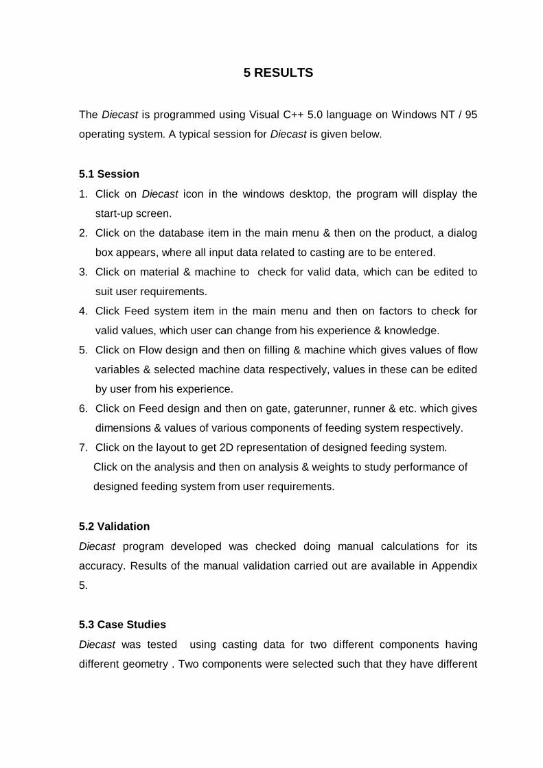
4.1.1 Product
It holds all the data about the casting required for performing feeding system
design. It gets the data either from user through interactive dialog box or through
text file generated from known 3D CAD system. It contains all information about
casting like name, number, weight, volume, length, width, height, projected area,
average thickness, maximum thickness, minimum thickness, surface area, casting
alloy, shape and its application. This acts as a primary input for calculation, which
can be edited by the user.
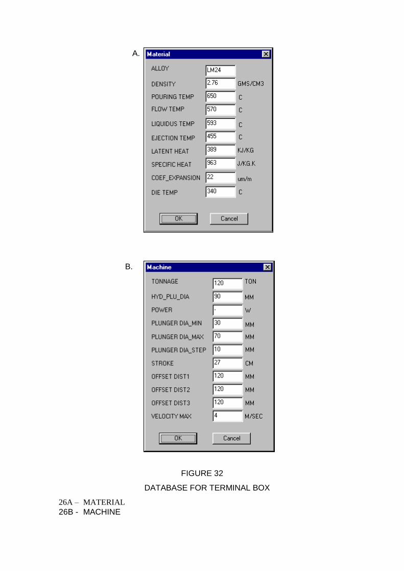
4.1.2 Material
It comprises of database which contain all the properties of material which are
required for feeding system design. Material properties like name, density,
pouring temperature, minimum flow temperature, liquidus temperature, ejection
temperature, latent heat, specific heat, coefficient of friction and recommended
die temperature are stored (Appendix 3). The material properties are accessed by
providing the material name as the input parameter, which is normally selected by
the user.
4.1.3 Machine
It comprises of technical specifications about machines which are required for
selection of appropriate machine for feeding system design. Specifications for the
range of commonly used machines are stored in this database. Typically it has
fields like machine tonnage, hydraulic plunger diameter, power, minimum plunger
diameter, maximum plunger diameter, plunger diameter steps, stroke, max
velocity and offset distances available with machine (Appendix 4). The specified
machine is first located in the database and the required specifications are then
retrieved.
4.2 Feed system
Feed system consist of different modules which does various calculations
required for feeding system design. Following are the different modules present
in the feed system – Factors, Flow design, Feed design, Layout, and Analysis.
4.2.1 Factors
It comprises of various empirical factors which are used for calculating different
variables of feeding system for Diecasting die. As the factors gets varied from
designer to designer and foundry to foundry, they can be edited by the user as
per his experience. Typically it holds values of factors for safety, maximum fill
ratio, minimum fill ratio, overflow, gate velocity, gate / casting thickness, maximum
gate thickness, runner / gate area, runner / gate thickness, venting, solidification.
4.2.2 Flow design
Flow design module is subdivided into two modules machine and filling (Fig.
19). In the machine module, first the opening force required for casting is

calculated, then based on the available machine database, machine which will
give optimum result is selected. Once machine selection is done plunger
diameter required for die is calculated which in turn is checked for its suitability
with selected machine. Best plunger location with respect to die center is then
decided.
Filling module first calculates filling time for a given casting, then it
calculates the fill velocity which will be required for filling the casting in calculated
time. Approximate shot weight is calculated for gating calculations.
4.2.3 Feed design
Feed design module calculates all dimensions related to feeding system it also
calculates machine settings parameters to get best results. Feed design is
subdivided into six modules which are as follows – Gate, Gaterunner, Runner,
Venting, Machine settings, and Result.
A) Gate
This module first calculates gate velocity for the feed system. Overflows weight is
calculated as per application category of casting. Based on the flow variables,
gate area required for feeding system is calculated, correspondingly gate
thickness and gate width are calculated.
Plunger velocity for achieving above results is calculated and is checked with
machine capability (Fig. 20).
B) Gaterunner
As per the type of gaterunner decided by gate module or from user input, it
calculates flow angle and approach angle of metal respect to casting. It then
computes dimensions of different cross sections and calculates its relative
location with respect to casting (Fig. 20).
C) Runner
Based on the design strategy runner crossection area and its other dimensions
like width and thickness are calculated. Velocity of metal in runner is calculated
for finding turbulence. Biscuit thickness for feeding system is then decided (Fig.
21).

D) Venting
Venting area is calculated based on application and gate area. Knowing the
venting depth venting width is calculated. Venting velocity is calculated which
gives some idea about air entrapment (Fig. 21).
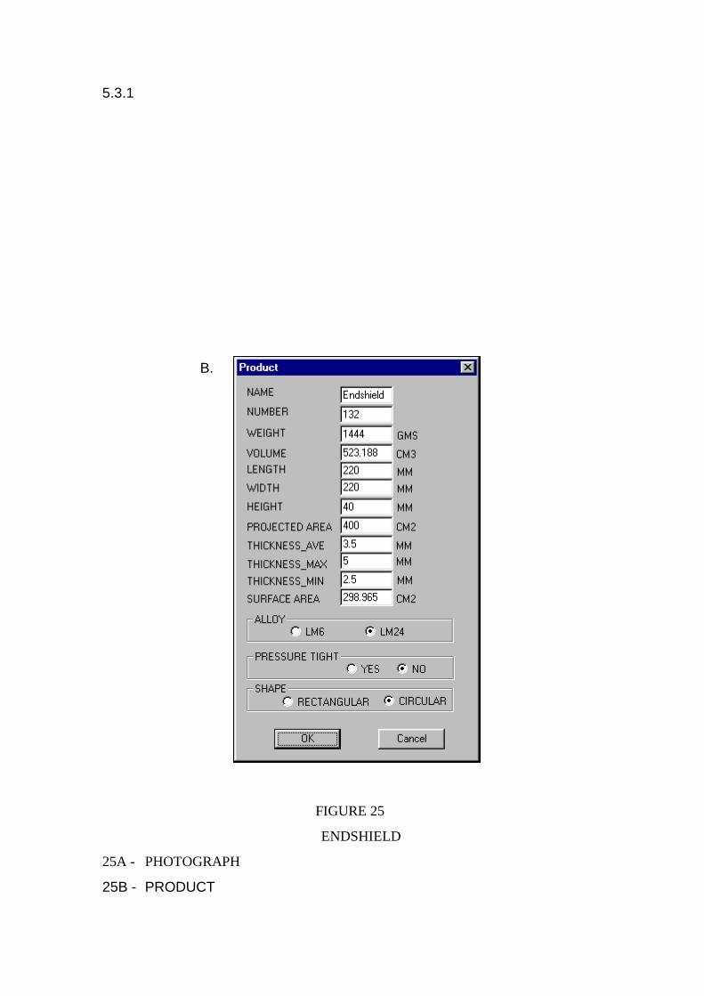
E) Machine settings
Based on the dimensions of feeding system and machine selected, process
variable settings required to achieve desired results are calculated, for that
locking force required, plunger velocity for first and second phase, accumulator
pressure, and critical point where first phase to second phase change takes place
are calculated (Fig. 22).
F) Result
This module calculates additional variables related to feeding system. It
calculates maximum flow path that can be achieved by the designed feed system.
It calculates pressure drop in gate, gaterunner and runner elements because of
metal flow. It calculates reynolds number in gate, gaterunner and runner cross
sections which gives indication about amount of turbulence present. It also
calculates rate of heat loss from gate, gaterunner and runner cross sections (Fig.
22).
4.2.4 Layout
This module gives the 2D representation of the designed feeding system based
on the dimensions and positional information calculated during feed design
module.
4.2.5Analysis
This modules evaluates the designed feeding system and shows performance of
same. It evaluates feeding system in terms of filling, air entrapment, yield,
machine power utilization and ease of fettling. It gives the final assessment of the
designed feeding system as per the weightage provided by the user for above
mentioned functions. This gives the user a clear cut picture of the designed
feeding system in terms of his requirement (Fig. 23).

4.3 Data Structure
An object oriented data structure is developed for representing the casting and
feeding system information. System is grouped into five main groups like Admin,
Product, Tooling, Process, Material (Fig. 24). Tooling is subdivided into
Machine_data, Die, Feed_system. Feed_system is further subdivided into
Machine, Factors, Filling, Gate, Gaterunner, Runner, Overflows, Venting,
Results, Analysis. This approach facilitates better abstraction of data and
recreation of usable objects. In the next chapter we will see the results obtained
from Diecast.
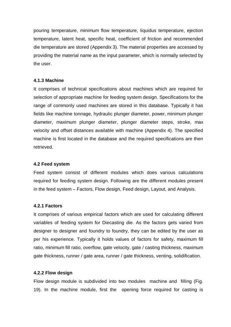
5 RESULTS
The Diecast is programmed using Visual C++ 5.0 language on Windows NT / 95
operating system. A typical session for Diecast is given below.
5.1 Session
1. Click on Diecast icon in the windows desktop, the program will display the
start-up screen.
2. Click on the database item in the main menu & then on the product, a dialog
box appears, where all input data related to casting are to be entered.
3. Click on material & machine to check for valid data, which can be edited to
suit user requirements.
4. Click Feed system item in the main menu and then on factors to check for
valid values, which user can change from his experience & knowledge.
5. Click on Flow design and then on filling & machine which gives values of flow
variables & selected machine data respectively, values in these can be edited
by user from his experience.
6. Click on Feed design and then on gate, gaterunner, runner & etc. which gives
dimensions & values of various components of feeding system respectively.
7. Click on the layout to get 2D representation of designed feeding system.
Click on the analysis and then on analysis & weights to study performance of
designed feeding system from user requirements.
5.2 Validation
Diecast program developed was checked doing manual calculations for its
accuracy. Results of the manual validation carried out are available in Appendix
5.
5.3 Case Studies
Diecast was tested using casting data for two different components having
different geometry . Two components were selected such that they have different

shape, size and require different type of gating. In the following pages are the
photographs of castings ,and results obtained from the Diecast.
5.3.1
B.
FIGURE 25
ENDSHIELD
25A - PHOTOGRAPH
25B - PRODUCT

A.
B.
FIGURE26
DATABASE FOR ENDSHIELD
26A – MATERIAL
26B - MACHINE

A.
C.
B.
FIGURE 27
FLOW DESIGN FOR ENDSHIELD
27A - FACTORS
27B - FILLING
27C - MACHINE

A. B.
C. D.
E.
FIGURE 28
FEED DESIGN FOR ENDSHIELD
28A – GATE
28B - GATERUNNER
28C - RUNNER
28D - OVERFLOWS
28E - VENTING
F.
G.
FIGURE 28F – M/C SETTINGS
28G– RESULTS

FIGURE 29
LAYOUT FOR ENDSHIELD

A.
B.
FIGURE 30
ANALYSIS FOR ENDSHIELD
30A – ANALYSIS
30B - WEIGHTS

Comparison Table
For Endshield Component
INPUT
Variables Calculated Actual
Casting Weight 1444 gms. 1444 gms.
Casting average thk. 3.5 mm 3.5 mm
Casting projected area 400 cm2 400 cm2
Application Non pressure Non pressure
tight tight
OUTPUT
Machine tonnage 400 Tons 400 Tons
Shot weight 1877 gms 1850 gms
Plunger diameter 60 mm 60 mm
Plunger velocity 1 0.712 m/s 0.75 m/s
Plunger velocity 2 3.701 m/s -
Gate area 261.49 mm2 260 mm2
Gate thickness 2.8 mm 2.6 mm
Gate width 93.39 mm 100 mm
Runner area 315.75 mm2 338 mm2
Runner thickness 12.87 mm 13 mm
Runner width 24.52 mm 26 mm
Venting area 52.29 mm2 52 mm2
Critical point 142.80 mm 140 mm

5.3.2
B.
FIGURE 31
TERMINAL BOX
31A - PHOTOGRAPH
31B - PRODUCT
A.
B.
FIGURE 32
DATABASE FOR TERMINAL BOX
26A – MATERIAL
26B - MACHINE

A.
C.
B.
FIGURE 33
FLOW DESIGN FOR TERMINAL BOX
33A - FACTORS
33B - FILLING
33C - MACHINE

A. B.
C. D.
E.
FIGURE 34
FEED DESIGN FOR TERMINAL BOX
34A – GATE
34B - GATERUNNER
34C - RUNNER
34B - OVERFLOWS
34C - VENTING

F.
G.
FIGURE 34F – M/C SETTINGS
34G– RESULTS

FIGURE 35
LAYOUT FOR TERMINAL BOX

A.
B.
FIGURE 36
ANALYSIS FOR TERMINAL BOX
36A – ANALYSIS
36B - WEIGHTS

COMPARISON TABLE
For Terminal Box Component
INPUT
Variables Calculated Actual
Casting Weight 230 gms. 230 gms.
Casting average thickness 4 mm 4 mm
Casting projected area 104 cm2 104 cm2
Application Non pressure tight Non pressure tight
OUTPUT
Machine tonnage 120 Tons 120 Tons
Shot weight 299 gms 310 gms
Plunger diameter 30 mm 30 mm
Plunger velocity 1 0.503 m/s 0.5 m/s
Plunger velocity 2 2.06 m/s -
Gate area 37.378 mm2 35 mm2
Gate thickness 1.2 mm 1.25 mm
Gate width 31.14 mm 28 mm
Runner area 90.32 mm2 87.5 mm2
Runner thickness 6.88 mm 7 mm
Runner width 13.11 mm 12.5 mm
Venting area 7.47 mm2 7 mm2
Critical point 44.46 mm 50 mm

6 CONCLUSIONS
6.1 Conclusions
This work “ Computer aided feeding system design for pressure Diecasting”
started with the objective of developing a PC based program, uses most of the
available knowledge on design rules, to assist a designer in the design of feeding
system.
It involved an extensive study of literature on feeding system design to
identify the knowledge base of the design rules. The Diecast has been
developed and implemented using object oriented programming methodology and
requires a personal computer for its execution. Considerable efforts has been
taken for verifying equations and logic used in the program.
Program is developed that takes into account technical requirements of the
product and selects machine based on its technical specifications. Program for
feeding system design calculates the required dimensions for various elements, it
provides figures showing the impact of design on casting filling, air entrapment,
machine power utilization, yield & fettling.
The Diecast has been tested on industrial casting samples and results are
included in the form of case studies in the present report.
The main achievements of this work are –
1. A systematic, logical presentation of the design rules for selection of machine,
design of gate, gaterunner, runner, overflows and venting for single cavity
single gating feeding system.
2. Successful development of the PC based software which can help in
designing feeding system of Diecasting die with greatly reduce time.
3. A number of case studies were carried out, illustrating the use of this work.
The program is designed to be a useful tool in hands of a die designer, assisting
in faster completion of jobs, & providing insight in the design process.

6.3 Future Work
The Diecast uses input in form of text file which is generated from known 3D CAD
system where as 3D CAD system can be integrated in the program for getting
casting data input as well as for representation of designed feeding system. The
program can be extended for multiple gating with inclusion of hot chamber
Diecasting process.
The program can be incorporated with filling simulation for the designed
feeding system, so that less numbers of iterations are required and it gives more
accurate results.

7 REFERENCES
1 Moorman J H , “Gating & Metal flow patterns in Pressure diecasting”, AFS
Transactions, vol 71, 1963, pp 929 – 940
2 Belopukhov A K , “Critical rates for spray filling in Pressure diecasting”,
Russian Casting Production, May 1974, pp 208 – 209
3 Wallace J F , “Gating of diecasting”, AFS Transcations, vol 73, 1965, pp 569
– 580
4 Russ Van Ress, “Gating Diecasting Dies”, North American Diecasting
Association, 1996
5 Davis A J , “Tapered runners feeding thin gates”, Transcations Society
Diecasting Casting Engineers, 1979, Paper G-T79-052
6 Makelskii M F , “Gating systems for Pressure diecasting”, Russian Casting
Production, September 1967, pp 413 – 416
7 Rodionov E M , “Influence of gating systems on quality of Pressure
diecasting”, Russian Casting Production, September 1974, pp No 397
8 Davis A J , “Some consequences of the relationship between the flow of
molten metal in feed systems and the concurrent flow of hydraulic fluid in
diecasting machines”, Transcations Society Diecasting Casting Engineers , 1975,
Paper G-T75-124
9 Draper A B , “Effect of vent and gate areas on the porosity of diecastings”,
AFS Transactions, vol 75, 1967, pp 727 – 734
10 Sheptak N , “Water analogy study of fluid flow in the cold chamber”, AFS
Transactions, vol 71, 1963, pp 349 – 357
11 Keil E , “The development of die”, Druckguss – Technical information Nr 6,
Gebruder Bhuler AG, Uzwil, 1985.
12 Prokhorov I I , “Nomographs for calculating Pressure diecasting conditions”,
Russian Casting Production, May1976, pp 198 – 199
13 Shvetsov V D , “Factors influencing the effectiveness of venting arrangement
in PDC dies”, Russian Casting Production, May 1975, pp 206 – 207
14 Chen C W , “Numerical simulation of filling pattern for an industrial diecasting
& its comparison with the defects distribution of an actual casting”, AFS
Transactions, vol 102, 1994, pp 139 – 146

15 Hwang W S , “Computer simulations for the filling of castings”, AFS
Transactions, vol 95 , 1987, pp 425 – 431
16 Estrin Len, “A deeper look at casting solidification software”, Modern casting,
July 1994, pp 20 – 23
17 Sloane David J , “Relationship between machine clamp and casting area in
aluminium diecasting”, AFS Transactions, vol 70, 1963, pp 442 – 448
18 Mostovshchk G , “Determining the injection & locking speeds in Pressure
diecasting machines”, Russian Casting Production, May 1975, pp 207 – 208
19 Rearwin Earle W , “Controlling variables in a diecast shop”, AFS
Transactions, vol 72, 1965, pp 865 – 871
20 Barton H K , “Controlling operational variables in diecasting”, AFS
Transactions, vol 70, 1963, pp 306 – 315
21 Akivis, “Plunger speeds in horizontal cold chamber PDC”, Russian Casting
Production, Feb 1968, pp 67
22 Arthur C Street, “The diecasting book”, Portcullis press, 2nd
edition, 1986
23 Ben Takach, “Die design, The weakest link in the chain”, Arkey Conference
Service Cell, Alucast, vol 4, 1998, pp 2 – 6
24 Kiselenko L E , “Influence of entry velocity on loss of lubrication & breakdown
of oxide dross in the PDC”, Russian Casting Production – March 1969 – pg No
123 – 124

Appendix 1
Table 1 Variables for cavity filling time calculations
Alloy Emprical constsnt, k Metal
injection
temp. Ti
Min.
Flow
temp. Tf
Die
cavity
temp. Td
Solids
Factor
Z
P20 H13 Tungste
n
Sec/ mm Sec/ mm Sec/ mm C C C C / %
Al 360 - 0.0346 0.0124 650 570 340 3.8
Al 380 - 0.0346 0.0124 650 570 340 3.8
Al 390 - 0.0346 0.0124 720 595 355 3.8
Zn 12,27 0.0312 0.0346 0.0124 565 445 260 3.2
Zn 3,5,7 0.0312 0.0346 0.0124 405 382 230 2.5
Mg - 0.0346 0.0124 650 510 340 2.5
Fe - 0.0346 0.0124 1540 1370 980 6.0
Cu
60/40
- 0.0346 0.0124 955 900 510 4.7
Table 2 Recommended values for gate velocity
Alloy Typical gate velocity m/sec J factor
Al 360 38.7 525
Al 380 38.7 525
Al 390 38.7 525
Zn 12,27 29.0 624
Zn 3,5,7 25.0 624
Mg 42.0 360
Fe 25.0 1314
Cu 60/40 22.5 985
Table 3 Recommended values for gate thickness.
Alloy Castings upto 100
gms.
Castings from 100
to 1000 gms.
Castings from 1000
to 5000 gms.
Zn alloy 0.3 – 0.6 0.5 – 1.2 0.8 – 1.5
Al alloy 0.5 – 1.0 0.8 – 1.8 1.5 – 3.5
Cu alloy 1.0 – 1.5 1.5 – 3.0 2.5 & more
Table 4 Recommended values of specific casting pressure.
Application Al & Mg alloys Zn alloys Cu alloys
Kg / cm2 Kg / cm2 Kg / cm2
Standard parts Upto 400 100 – 200 300 – 400
Technical parts 400 – 600 200 – 300 400 – 500
Pressure tight parts 800 – 1000 250 – 400 800 – 1000
Chromium plating parts - 200 – 250 -
Table 5 List of softwares and their capabilities

Name Platforms Strengths and Capabilities
Cap ,Amesh PC , SGI
worksations
Short time required for analysis execution, efficient use of
memory, FEM allows accurate representation of geometry,
AMESH mesh generator tailored specifically to casting
applications. A post-processor is also available.
Magma soft Unix based
systems
It features modules dedicated to – project management,
pre-processing, fluid dynamics, and heat flow processing,
post-processing, thermophysical data collection. Its
capabilities include a powerful flow solver for fluid flow
problems, such as misruns and cold-shuts, direct
visualization of problem areas, ability to run multiple
cycles, ability to quickly model complex castings such as
cylinder heads etc.
Procast Unix based
systems
Using FEM Procast solves fully coupled thermal-fluid-
stress-electromagnetic problems. Nonlinear stress can be
modeled along with thermal mechanical contact at
material interfaces. Micromodeling is also included for
providing detailed information about microstructure and
mechanical properties. The user-friendly motif based
interface contains databases, automatic mesh generation
capabilities and sophisticated visulization tools.

Appendix 2
Variables affecting diecasting process along with abbreviations used in program.
Casting related
1. Casting volume ( cv ).
2. Casting weight ( cwt ).
3. Casting average thickness ( cat ).
4. Casting minimum thickness ( cmt ).
5. Casting projected area ( cpa).
6. Casting length max. ( cl ).
7. Casting width max. ( cw ).
8. Casting surface area ( csa ).
9. Casting height max. ( ch ).
10. Casting alloy ( ca ).
11. Casting application ( cap ).
12. Casting number ( cn ).
13. Casting name ( can ).
Material related
1. Density ( md ).
2. Pouring temperature ( mpt ).
3. Minimum flow temperature ( mft ).
4. Liquidous temperature ( mlt ).
5. Specific heat ( msh ).
6. Latent heat ( mlh ).
7. Coefficient of friction ( mf ).
Die related
1. Shot weight ( dsw ).
2. Opening force ( dof ).
3. Plunger diameter ( dpd ).
4. Specific cavity pressure ( dcp ).
5. Fill ratio ( dfr ).
6. Die temperature ( dt ).
7. Ejection temperature ( det ).
8. Number of cavities ( dnc ).
9. Cavity fill time ( dct ).
10. Gate location ( dgl ).
11. Number of gates ( dng ).
12. Number of overflows ( dno ).
13. Weight of overflows ( dwo ).
14. Venting area ( dva ).
15. Venting width ( dvw ).
16. Gate velocity ( dgv ).
17. Gate thickness ( dgt ).
18. Gate area ( dga ).
19. Gate land ( dgl ).
20. Gate width ( dgw ).
21. Approach angle ( daa ).
22. Runner thickness ( drt ).
23. Runner area ( dra ).
24. Runner width ( drw ).
25. Runner length ( drl ).
26. Runner velocity ( drv ).
27. Biscuit thickness ( dbt ).
28. Percent solid fraction allowable ( dsf ).
Diecasting machine related
1. Locking force i.e tonnage ( dmlf ).
2. Plunger offset distance ( dmpod ).
3. Shot sleeve length ( dmsl ).
4. Shot sleeve diameter ( dmsd ).
5. Shot capacity ( dmsc ).
6. Plunger velocity 2nd
phase ( dmpv2 ).

7. Plunger velocity 1st phase ( dmpv1 ).
8. Plunger diameter ( dmpd ).
9. Plunger stroke ( dmps ).
10. Horizontal distance between tie bar ( dmhd ).
11. Vertical distance between tie bar ( dmvd ).
Diecasting factors
1. Factor of safety for machine selection ( dffos ).
2. Shot capacity factor ( dfsc ).
3. Fill ratio factor ( dffr ).
4. Overflow factor ( dfo ).
5. Gate velocity factor ( dfgv ).
6. Gate thickness factor ( dfgt ).
7. Gate area to runner area ( dfgara ).
8. Gate thickness to runner thickness ( dfgtrt ).
9. Venting factor ( dfv ).
10. Machine to plunger stroke ( dfmps ).
11. Pressure drop ( dfpd ).
12. Heat loss ( dfhl ).

APPENDIX 3
Material database
ALLOY LM24 LM6 A390
DENSITY (gms/cm3) 2.76 2.76 2.76
POURING TEMP. (C) 650 650 720
MIN. FLOW TEMP (C) 570 570 595
LIQUIDUS TEMP. (C) 593 593 663
EJECTION TEMP. (C) 455 455 455
LATENT HEAT(kJ/kg) 389 389 389
SPECIFIC HEAT(J/kg.K) 963 963 963
COEF. EXPAN. (um/m) 22 22 25
DIE TEMP. (C) 340 340 355
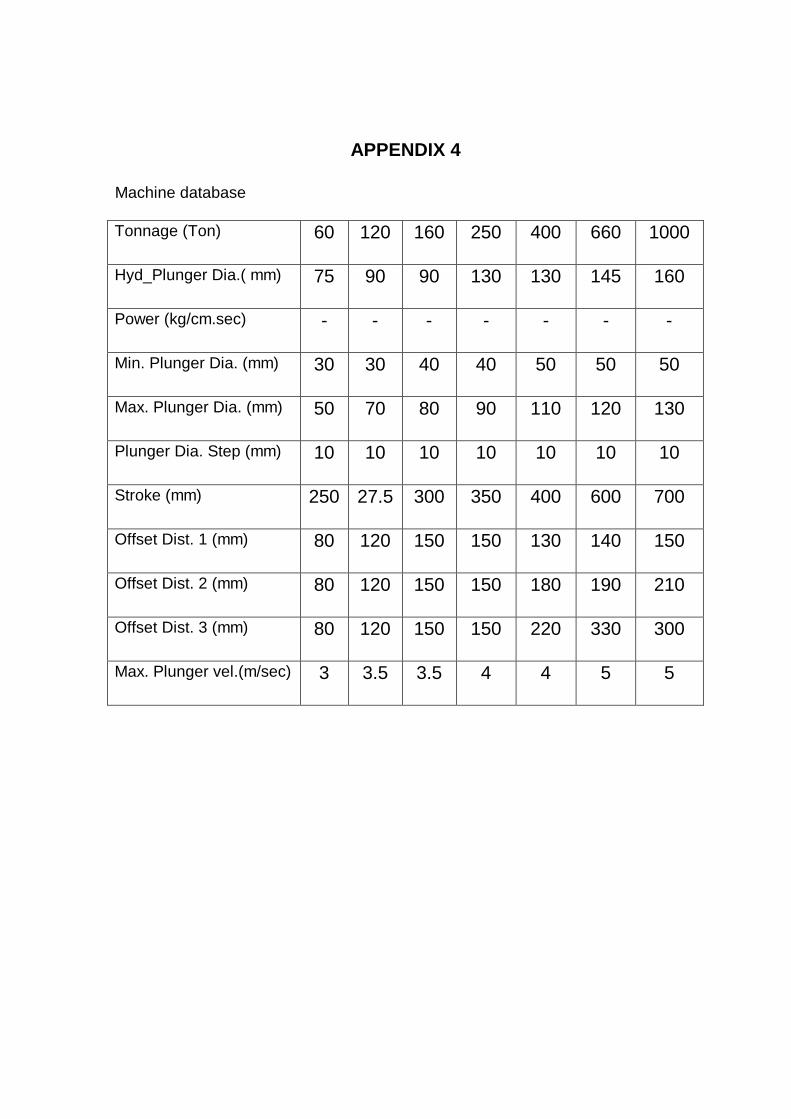
APPENDIX 4
Machine database
Tonnage (Ton) 60 120 160 250 400 660 1000
Hyd_Plunger Dia.( mm) 75 90 90 130 130 145 160
Power (kg/cm.sec) - - - - - - -
Min. Plunger Dia. (mm) 30 30 40 40 50 50 50
Max. Plunger Dia. (mm) 50 70 80 90 110 120 130
Plunger Dia. Step (mm) 10 10 10 10 10 10 10
Stroke (mm) 250 27.5 300 350 400 600 700
Offset Dist. 1 (mm) 80 120 150 150 130 140 150
Offset Dist. 2 (mm) 80 120 150 150 180 190 210
Offset Dist. 3 (mm) 80 120 150 150 220 330 300
Max. Plunger vel.(m/sec) 3 3.5 3.5 4 4 5 5

APPENDIX 5
Key calculations for endshield component –
1. Shot weight = dfsc x cwt = 1877 gms.
2. Casting pressure = 600 kg / cm2 ( non pressure tight castings ).
3. Opening force = dcp x cpa /1000 = 288 Tons.
4. Machine selected = 400 Tons.
5. Plunger area = dsw / ( md x dffr x dgv ) = 24.28 cm2.
6. Plunger diameter = 56.61 mm.
7. Plunger diameter selected = 60 mm.
8. Fill time = k x cat x ( mpt – mft + SZ ) / ( mft – dt ) = 0.050.
9. Gate velocity selected = 40 m/s.
10. Gate area = ( cwt + dwo) / ( dgv x md x dct ) = 261.59 mm2.
11. Gate thickness = dfgt x cat = 2.8.
12. Gate length = dga / dgl = 93.39.
13. Gate runner cross section = dfgara x dga = 300.82.
14. Venting area = dfv x dga = 52.31 mm2.
15. Hyd. Dia at gate = 4 x area / perimeter = 5.43 mm.
16. Reynolds number at gate = dgv x hyd . dia / ( 10 x viscocity ) = 3620.
17. Heat loss at gate = dfhl x ( dgw + dgt ) = 1978.7 W.
18. Pressure drop at gate = dfpd x dgv x dgv = 62.5 bar.

APPENDIX 6
Output file for endshield component -
BEGIN MACHINE
MACHINE_REQD 400(tons)
PLUNGER_DIA 60(mm)
PLUNGER_STROKE 400(mm)
PLUNGER_OFFSET 220(mm)
SHOT_SLEEVE_LEN 405(mm)
PLUNGER_VELOCITY1 0.712061(m/sec)
PLUNGER_VELOCITY2 3.70268(m/sec)
SHOT_CAPACITY 3119.9(gms)
BEGIN FILLING
SHOT_WEIGHT 1877.2(gms)
CASTING_PRESSURE 600(kg/cm2)
FILL_VELOCITY 40(m/sec)
FILL_TIME 0.05(sec)
BEGIN GATE
GATE_AREA 261.594(mm2)
GATE_WIDTH 93.4265(mm)
GATE_THICKNESS 2.8(mm)
GATE_VELOCITY 40(m/sec)
GATE_LAND 0.933333(mm)
BEGIN GATERUNNER
GATERUNNER_AREA1 266.499(mm2)
GATERUNNER_WIDTH1 66.9082(mm)
GATERUNNER_THK1 3.98306(mm)
GATERUNNER_AREA2 271.404(mm2)
GATERUNNER_WIDTH2 52.5354(mm)

GATERUNNER_THK2 5.16611(mm)
GATERUNNER_AREA3 281.214(mm2)
GATERUNNER_WIDTH3 37.3348(mm)
GATERUNNER_THK3 7.53222(mm)
GATERUNNER_AREA4 291.024(mm2)
GATERUNNER_WIDTH4 29.4013(mm)
GATERUNNER_THK4 9.89834(mm)
GATERUNNER_AREA5 300.833(mm2)
GATERUNNER_WIDTH5 24.5289(mm)
GATERUNNER_THK5 12.2644(mm)
GATERUNNER_AREA6 300.833(mm2)
GATERUNNER_WIDTH6 24.5289(mm)
GATERUNNER_THK6 12.2644(mm)
GATERUNNER_AREA7 300.833(mm2)
GATERUNNER_WIDTH7 24.5289(mm)
GATERUNNER_THK7 12.2644(mm)
GATERUNNER_AREA8 300.833(mm2)
GATERUNNER_WIDTH8 24.5289(mm)
GATERUNNER_THK8 12.2644(mm)
GATERUNNER_AREA9 300.833(mm2)
GATERUNNER_WIDTH9 24.5289(mm)
GATERUNNER_THK9 12.2644(mm)
BEGIN RUNNER
RUNNER_AREA 315.875(mm2)
RUNNER_WIDTH 24.5289(mm)
RUNNER_THICKNESS 12.8777(mm)
RUNNER_LENGTH 35(mm)
RUNNER_VELOCITY 33.1263(m/sec)
BEGIN OVERFLOWS
OVERFLOWS_WEIGHT 0(gms)
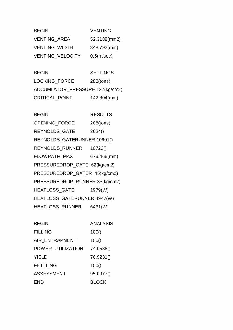
BEGIN VENTING
VENTING_AREA 52.3188(mm2)
VENTING_WIDTH 348.792(mm)
VENTING_VELOCITY 0.5(m/sec)
BEGIN SETTINGS
LOCKING_FORCE 288(tons)
ACCUMLATOR_PRESSURE 127(kg/cm2)
CRITICAL_POINT 142.804(mm)
BEGIN RESULTS
OPENING_FORCE 288(tons)
REYNOLDS_GATE 3624()
REYNOLDS_GATERUNNER 10901()
REYNOLDS_RUNNER 10723()
FLOWPATH_MAX 679.466(mm)
PRESSUREDROP_GATE 62(kg/cm2)
PRESSUREDROP_GATER 45(kg/cm2)
PRESSUREDROP_RUNNER 35(kg/cm2)
HEATLOSS_GATE 1979(W)
HEATLOSS_GATERUNNER 4947(W)
HEATLOSS_RUNNER 6431(W)
BEGIN ANALYSIS
FILLING 100()
AIR_ENTRAPMENT 100()
POWER_UTILIZATION 74.0536()
YIELD 76.9231()
FETTLING 100()
ASSESSMENT 95.0977()
END BLOCK

Acknowledgement
I am extremely grateful to my guide, Prof B Ravi, who has been my source of
inspiration, and whose constant encouragement has led to fruition of this work
My sincere thanks to Casting lab members for their suggestions and help