computational modelling of high-cycle fatigue using … · key words: high-cycle fatigue;...
TRANSCRIPT

28th Nordic Seminar on Computational MechanicsNSCM-28
A. Berezovski, K.Tamm, T.Peets (Eds.)c©TUT, Tallinn, 2015
COMPUTATIONAL MODELLING OFHIGH-CYCLE FATIGUE USING ACONTINUUM BASED MODEL
SAMI HOLOPAINEN∗, REIJO KOUHIA∗, JUHO KONNO†
AND TIMO SAKSALA∗
∗Department of Mechanical Engineering and Industrial SystemsTampere University of Technology
e-mail: [email protected] - Web-page: http://www.tut.fi/
†Research & Development, Wartsila Finland Oye-mail: [email protected] - Web page: http://www.wartsila.com
Key words: high-cycle fatigue; transverse isotropy, endurance surface, AbaqusUMAT
Summary. In this paper a computational implementation of continuum basedtransversally isotropic fatigue model is described. The key idea of the continuumbased HCF-model is the moving endurance surface where the movement is describedby a back stress type tensor, the evolution of which is described by a rate type equa-tion. Furthermore, damage accumulation is also governed with a rate type evolutionequation. The model is implemented in the Abaqus FE-program using the user ma-terial subroutine. Two strategies to perform a fatigue analysis are compared in astandard cycling loading case. The first analysis reflects the procedure used in a stan-dard fatigue computation. In the second analysis type the effect of evolving damagefields on fatigue life is investigated.
1 INTRODUCTION
Fatigue of materials under variable loads is a complicated physical process whichcan even result in catastrophic failure of engineering components. It is character-ized by nucleation, coalescence and stable growth of cracks. Nucleation of cracksstarts from stress concentrations near persistent slip bands, grain interfaces and in-clusions1,2,3.
In high-cycle fatigue, the macroscopic behavior of the material is primarily elastic,while in the low-cycle fatigue regime considerable macroscopic plastic deformationstake place. Transition between low- and high-cycle fatigue occurs between 103 − 104
cycles. In recent years, it has been observed that fatigue failures can occur at veryhigh fatigue lives 109 − 1010, below the previously assumed fatigue limits.
In this paper only high-cycle fatigue modelling is considered. Many different ap-proaches have been proposed to model the high-cycle fatigue behaviour which canroughly be classified into stress invariant, or average stress based and critical plane
71

Sami Holopainen, Reijo Kouhia, Juho Konno and Timo Saksala
approaches. In those approaches damage accumulation is usually based on cycle-counting, which makes their use questionable under complex load histories4,5.
A different strategy for high-cycle fatigue modelling was proposed by Ottosen etal.4. In their approach, which could be classified as evolutionary, the concept of amoving endurance surface in the stress space is postulated together with a damageevolution equation. The endurance surface is expressend in terms of the second invari-ant of the reduced deviatoric stress tensor where the center of the surface is definedby a deviatoric back stress tensor, as is done similarly in kinematic plasticity models.Therefore, the load history is memorized by the back-stress tensor. In this modelarbitrary stress states are treated in a unified manner for different loading histories,thus avoiding cycle-counting techniques.
In the present paper, some experiences of the finite element implementation of thetransversally isotropic fatigue6 model is given. The model is based on the idea byOttosen et al.4.
2 MODEL FORMULATION
The continuum fatigue model developed in6 is briefly described. It is based onthe assumption that a material exhibit loading condition dependent endurance limitswithin which no damage results under cyclic loading. Ottosen et al.4 proposed amoving endurance surface in stress stress space to account for these limits. Thekye idea of the transversally isotropic model is to split the stress tensor into thelongitudinal and transverse parts σ = σL + σT, where the transverse component isobtained from
σT = PσP = σ − σB −Bσ + σbB , (1)
whereP is the projection tensor, P = I−B , andB = b⊗b is the structural tensor fortransverse isotropy, The unit vector b designates the privileged longitudinal direction.The endurance surface for transversely isotropic fatigue has the form6
β =1
ST{σ +ALIL1 +ATIT1 − [(1− ζ)ST + ζSL]} = 0, (2)
where the linear invariants of the longitudinal and transverse stress tensors are
IL1 = trσL = I4 = tr (σB), IT1 = trσT = trσ − tr (σB). (3)
Endurance limits at zero mean stress in the longitudinal and transverse directions aredenoted as SL and ST, rspectively. Non-dimensional positive parameters AL and AT
are related in a constant amplitude cyclic loading to the slope in the Haigh diagram.Moreover, σ in (2) is the effective stress defined in terms of the second invariant ofthe reduced deviatoric stress s −α, with α being the back stress type tensor, as
σ =√
32 (s −α) : (s −α), (4)
where s = σ− 13 tr (σ)I is the deviatoric stress tensor, I stands for the identity tensor.
The scalar variable ζ reflects the average loading direction and is defined as
ζ =(
σL : σL
σ : σ
)n
=2I5 − I24
2I2, (5)
72

Sami Holopainen, Reijo Kouhia, Juho Konno and Timo Saksala
where the invariants I2 = 12 trσ
2, I5 = tr (σ2B).
The endurance surface, β = 0, moves in the stress space driven by the back stresswhich memorizes the load history. Contrarily to plasticity theory, the stress statesout of the endurance surface, β > 0, are allowed. The final model component neededbefore specifying the damage formulations is the evolution law for the back stresstensor. For this end, a hardening rule similar to Ziegler’s kinematic hardening rule inplasticity theory is adopted, i.e.
α = C(s −α)β, (6)
where C is a non-dimensional material parameter, and the dot denotes time rate.In the original formulation by Ottosen et al.4 a scalar damage variable is chosen to
descibe the material deterioration. In the present study the chosen evolution equationfor the damage D is
D =K
1−Dexp(Lβ)β, (7)
where K and L are material parameters to be estimated from experiments. It differsby the factor 1/(1 − D) from the one used by Ottosen et al.4. From the evolutionequation (7) it can be concluded that damage and the backstress only developes whenthe stress state is moving away from the endurance surface, that is β ≥ 0 and β > 0.
3 EXAMPLE
Above model has been implemented in the finite element program Abaqus usingthe user material subroutine. As an example, a plate in plane strain conditionswith a circular inclusion under uniaxial cyclic loading is considered. Diameter ofthe inclusion is 40 % of the side length of the domain. Due to symmetry only onequarter is discretized. Analytical solution for an infinite plate with a circular inclusionis given by Sezewa and Nishimura7. The surprizing result of their solution is thatirrespectively of the stiffness difference bewteen the base material and the inclusion,all the stressess in the inclusion are constant along a radius but not along an azimuthaldirection.
In the present analysis the material parameter have been determined for the AISI-SAE 4340 steel and they are SL = ST = S0 = 490 MPa, AL = AT = A = 0.225, C =0.11,K = 1.46·10−5 and L = 8.7. Elastic properties for the base material are E = 210GPa and ν = 0.3, and E = 375 GPa, ν = 0.22 for the aluminium oxide inclusion,respectively. Only the base material is accounted for in the fatigue analysis. Uniformnormal stress along the upper boundary is prescribed as σy = S0 sinωt.
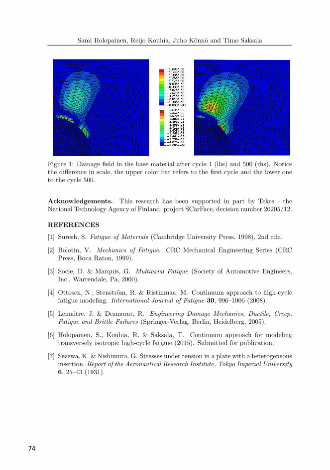
Damage variable fields in the base material after the first and 500th cycle are shownin Fig. 1. As it can be noticed, the most damaging areas change during the materialdegradation due to the backstress as a driving force of damage. Therefore fatigueanalysis based on single cycle stress history and linear accumulation of damage doesnot result in correct life-time prediction. The fatigue life based only on the first cyclestress history at the most critical point is 2.6 ·106 cycles. However, if it is determinedfrom the damage history of the first 500 cycles, the lifetime is only 1.5 · 104 cycles.Another interesting observation is that a region of pronounced damage does not solelyemerge around the inclusion but also inside the base material roughly at distance onethird of the inclusion’s radius from its interface.
73
Sami Holopainen, Reijo Kouhia, Juho Konno and Timo Saksala
Figure 1: Damage field in the base material after cycle 1 (lhs) and 500 (rhs). Noticethe difference in scale, the upper color bar refers to the first cycle and the lower oneto the cycle 500.
Acknowledgements. This research has been supported in part by Tekes - theNational Technology Agency of Finland, project SCarFace, decision number 20205/12.
REFERENCES
[1] Suresh, S. Fatigue of Materials (Cambridge University Press, 1998), 2nd edn.
[2] Bolotin, V. Mechanics of Fatigue. CRC Mechanical Engineering Series (CRCPress, Boca Raton, 1999).
[3] Socie, D. & Marquis, G. Multiaxial Fatigue (Society of Automotive Engineers,Inc., Warrendale, Pa, 2000).
[4] Ottosen, N., Stenstrom, R. & Ristinmaa, M. Continuum approach to high-cyclefatigue modeling. International Journal of Fatigue 30, 996–1006 (2008).
[5] Lemaitre, J. & Desmorat, R. Engineering Damage Mechanics, Ductile, Creep,
Fatigue and Brittle Failures (Springer-Verlag, Berlin, Heidelberg, 2005).
[6] Holopainen, S., Kouhia, R. & Saksala, T. Continuum approach for modelingtransversely isotropic high-cycle fatigue (2015). Submitted for publication.
[7] Sezewa, K. & Nishimura, G. Stresses under tension in a plate with a heterogeneousinsertion. Report of the Aeronautical Research Institute, Tokyo Imperial University
6, 25–43 (1931).
74