computational continuum mechanics for sediment transport...
TRANSCRIPT

Computational continuum mechanics for sedimenttransport in free-surface flow
Patricio Bohorquez
Escuela Tecnica Superior de Ingenieros Industriales
Universidad de Malaga
Spain
Open Source CFD International Conference 2008
4th/5th December 2008
Berlin, Germany
Computational continuum mechanics for sediment transport in free-surface flow – p. 1
Geomorphic shallow water models
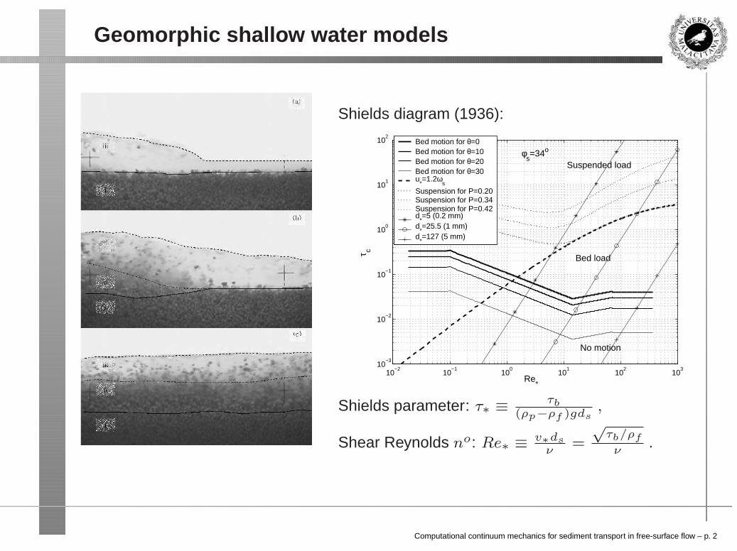
Shields diagram (1936):
10−2
10−1
100
101
102
103
10−3
10−2
10−1
100
101
102
Re*
τ c
φs=34o
Bed motion for θ=0Bed motion for θ=10Bed motion for θ=20Bed motion for θ=30u
*=1.2ω
s
Suspension for P=0.20Suspension for P=0.34Suspension for P=0.42d
*=5 (0.2 mm)
d*=25.5 (1 mm)
d*=127 (5 mm)
Suspended load
Bed load
No motion
Shields parameter: τ∗ ≡ τb(ρp−ρf )gds
,
Shear Reynolds no: Re∗ ≡ v∗dsν
=
√τb/ρf
ν.
Computational continuum mechanics for sediment transport in free-surface flow – p. 2
Structural features in dense suspensions
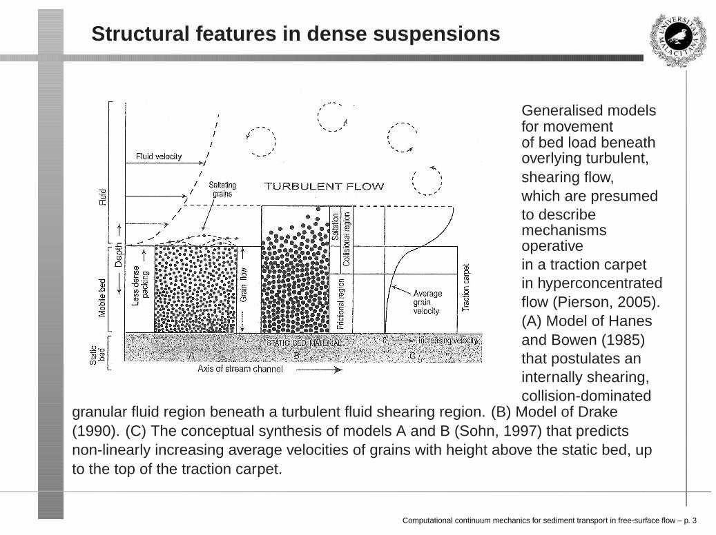
Generalised modelsfor movementof bed load beneathoverlying turbulent,shearing flow,which are presumedto describemechanismsoperativein a traction carpetin hyperconcentratedflow (Pierson, 2005).(A) Model of Hanesand Bowen (1985)that postulates aninternally shearing,collision-dominated
granular fluid region beneath a turbulent fluid shearing region. (B) Model of Drake(1990). (C) The conceptual synthesis of models A and B (Sohn, 1997) that predictsnon-linearly increasing average velocities of grains with height above the static bed, upto the top of the traction carpet.
Computational continuum mechanics for sediment transport in free-surface flow – p. 3

CCM: three-phase mixture model (I)
The main mixture properties are the density (ρ), the ensemble averaged velocity of themass centre (〈~v〉), and the ensemble-averaged volumetric flux (〈~u〉), which are given by
ρ = ρmγ + ρg(1 − γ) (1)
〈~v〉 =1
ρ[γρm〈~vm〉 + (1 − γ)ρg〈~vg〉] (2)
〈~u〉 ≡ γ〈~um〉 + (1 − γ)〈~vg〉 (3)
where the density (ρm) and the velocity of the centre of mass (< ~vm >) and volume(< ~um >) in the water-sediment suspension are
ρm = ρpβ
γ+ ρf
„
1 − β
γ
«
(4)
〈~vm〉 ≡ 1
ρm
»
β
γρp〈~vp〉 +
„
1 − β
γ
«
ρf 〈~vf 〉–
(5)
〈~um〉 ≡ β
γ〈~vp〉 +
„
1 − β
γ
«
〈~vf 〉 (6)
Computational continuum mechanics for sediment transport in free-surface flow – p. 4

CCM: three-phase mixture model (II)
The definitions established above are functions of the solid particle volumetricconcentration (αp ≡ β), the air volumetric concentration (αg ≡ 1 − γ), and the liquidvolumetric concentration (αf = γ − β) in the three-phase mixture. Thus, theconservation equations of the multi-fluid system can be reduced to the mixture forms:
∂ρ
∂t+ ∇ · (ρ〈~v〉) = 0 , (7)
∂γ
∂t+ ∇ · (γ〈~u〉) + ∇ · [γ(1 − γ)〈~urγ〉] = 0 , (8)
∂β
∂t+ ∇ · (β〈~u〉) + ∇ · [β(1 − β)〈~urβ〉] = 0 , (9)
∂ρ〈~v〉∂t
+ ∇ · (ρ〈~v〉〈~v〉) = −∇〈p〉 − ∇〈ps〉 + ∇ · 〈τ〉 − σκ∇γ − ~g · ~x∇ρ , (10)
〈τ ′〉 + 〈τ ′′〉 = (µl + µt)
»
∇〈~v〉 + (∇〈~v〉)T − 2
3(∇ · 〈~v〉) I
–
, (11)
τ′′′ ≡ γ(1 − γ)
ρmρg
ρ~vrγ~vrγ , τ
′′′′ ≡ β
„
1 − β
γ
«
ρf ρp
ρm~vr~vr (12)
Computational continuum mechanics for sediment transport in free-surface flow – p. 5

CCM: three-phase mixture model (III)
One of the most noticeable effects of the relative velocity in the particle-fluid mixture isthe difference arising between the mass velocity ~v and the volume flux ~u, associated withthe motion of the centre of mass and centre of volume, respectively.
~v = ~u + γ(1 − γ)ρm − ρg
ρ~urγ + βs
γ − β
γ + βs
ρm
ρ~vr . (13)
The fact that the mass transfer is not necessarily accompanied by a similar volumetransfer is now evident.
Most researchers in hydraulic engineering neglect the relative velocities ~vr and ~urβ inour mixture model. Under this hypothesis, neither erosion, deposition, or lag velocitiescan be modelled. Moreover, the constitutive relations for the stress tensor of the mixtureare not taken into account.
Computational continuum mechanics for sediment transport in free-surface flow – p. 6

Dam-break flow against an isolated obstacle (I)
picture from J. Hydraul. Res., 45 (Extra Issue): 27–36, 2007.
Computational continuum mechanics for sediment transport in free-surface flow – p. 7

Dam-break flow against an isolated obstacle (II)
Computational continuum mechanics for sediment transport in free-surface flow – p. 8

Dam-break flow against an isolated obstacle (III)
0 1 2 3 4 50
0.01
0.02
0.03
0.04
0.05
0.06
0.07
0.08
0.09
t
h
Experiment (trans)2D Coolebrock & White2D Ideal3D laminar3D k−ε
Test case: J. Hydraul. Eng. 134 (8): 1089–1101, 2008.
Computational continuum mechanics for sediment transport in free-surface flow – p. 9

Erosional dam-break flow (I)
Test case: H. Capart and D. L. Young. Formation of a jump by the dam-break wave overa granular bed. J. Fluid Mech., 372: 165–187, 1998.
Computational continuum mechanics for sediment transport in free-surface flow – p. 10

Erosional dam-break flow (II)
Test case: J. Hydraul. Res., 45 (Extra Issue): 73–86, 2007.
Computational continuum mechanics for sediment transport in free-surface flow – p. 11