computational aeroelasticity in high performance aircraft flight loads
TRANSCRIPT

ICAS 2000 CONGRESS
481.1
COMPUTATIONAL AEROELASTICITY IN HIGHPERFORMANCE AIRCRAFT FLIGHT LOADS*
Mike Love, Tony De La Garza, Eric Charlton, Dan EgleLockheed Martin Aeronautics Company
Keywords: computational aeorelasticity, CFD, flight loads
* Copyright © 2000 Lockheed Martin Corporation All rightsreserved. Published by the International Council ofAeronautical Sciences with permission.
Abstract
A computational aeroelasticity methodhas been developed that combines a compu-tational fluid dynamics (CFD) code based ona finite volume, Cartesian / prismatic gridscheme with automated unstructured gridcreation and adaption with establishedstructural finite element methods. Thisanalysis is motivated by the need to developan analysis capability for fighter-aircraftcritical flight loads. Flight conditions forsuch often reside in transonic flow regimesand comprise nonlinear aerodynamics due toshocks, flow-separation onset, and complexgeometry. The Multidisciplinary Computa-tional Environment, MDICE [1], is provid-ing for timely integration of LockheedMartin’s CFD software, SPLITFLOW [2] ina maintenance friendly, loosely couplednonlinear analysis method. Analysis corre-lation with static aeroelastic wind tunneldata demonstrates potential. Analysis set-upand results for a fighter aircraft with multi-ple control surfaces are demonstrated.
1 Introduction
Computational aeroelasticity, or computa-tional fluid dynamics (CFD) based aeroelas-ticity, is an emerging technology with highpotential for the development of criticalflight loads (Figure 1). The structural designof flight vehicles is highly dependent on thetimeliness of accurate design flight loads.Flight loads are typically derived by com-bining aerodynamic loads, vehicle inertia,structural flexibility, and flight control laws
Figure 1: Pressures and streamlines obtained from acomputational aeroelastic maneuver simulation
in maneuver simulations. The Loads engi-neer’s time is mostly consumed in theassembly of accurate data for the maneuversimulation. Adequate characterization ofvehicle aerodynamics is critical. Recent tooland technology developments are facilitatingthe aerodynamic characterization task ofintegrating data from CFD methods, windtunnel testing and other aerodynamic meth-ods to assemble an aerodynamic pressuredatabase [3, 4]. This database is augmentedby static aeroelastic analyses to account forflexibility effects of the structure and inertialeffects of the flight vehicle. These analysesare performed at a distributed set of Machnumber and altitude combinations. Histori-cally, a linear static aeroelastic solution isacquired for each nonlinear rigid aerody-namic data set using linear aerodynamicpanel methods. Linear methods do not

Love, De La Garza, Charlton, Egle
481.2
capture nonlinear phenomenon such as flowseparation and moving shocks in the criticalloads flight regime.
Figure 2 illustrates the construction andtopology of a database for fighter loads.Literally thousands of aerodynamic pressurevectors are constructed over a distribution ofMach numbers, altitudes, and control pa-rameter angles. The database is considerednonlinear because the integrated aerody-namic load coefficients (e.g., lift coefficientdue to angle of attack) are nonlinear withrespect to control parameters such as angleof attack, sideslip, delta-aileron and delta-horizontal-pitch-trim. These aerodynamicvectors are used in determining the inte-grated aerodynamic load corresponding to agiven maneuver simulation. Maneuversimulations are performed using a nonlineariterative algorithm that computes controlparameter angles necessary to satisfy equilib-rium conditions about the vehicle’s center ofgravity. The algorithm is iterative because itis interpolating on the aerodynamic pressurevectors representing the control parameterstates closest to the current trim parameterprediction. An example integrated aerody-namic load is depicted in (1), where eachterm represents the contribution of onset-
flow, control surface, rotary rate, and accel-eration parameters, respectively.
RR
PQ
Q
PP
P
P
NN
PN
N
PN
N
P
RR
PQ
Q
PP
P
P
PPP
PPPLift
LLL
ZZ
LY
Y
LX
X
L
LLL
RR
LA
A
LE
E
L
LLL
&&
&&
&& ∂
∂+∂∂+
∂∂+
∂∂+
∂∂+
∂∂+
∂∂+
∂∂+
∂∂+
∂∂+
∂∂+
∂∂+
∂∂+
∂∂+=
δδ
δδ
δδ
ββ
αα0
(1)
At the equilibrium state of the vehicle ina maneuver (e.g., 9g symmetrical pull-up or5.86g asymmetric rolling pullout), inertiaforces are balanced with aerodynamic forcesat the current control parameter values. Theaccuracy of the flight loads is highly depend-ent on the accuracy of each component ofaerodynamic load. The Loads engineerendeavors to create a database where eachaerodynamic pressure vector is correlated tophysically known quantities. The largedatabase provides an environment forexpedient computation of thousands of flightmaneuver simulations surveying the flightenvelope for critical component designloads.
2-D LoadsIntegration Model
Nonlinear RigidPressure Data
Linear FlexibleIncrement
FLEXIBLENONLINEAR
AERODYNAMICPRESSUREDATABASE
Typical Nonlinear Aerodynamic Database
• Onset Flow Effects Only 250• 1st Order Control Surface Effects 4800• 2nd Order CS Interaction Effects 60000
• Aeroelastic Increments For Each Case
# Simulations
PressureMapping
AeroelasticAnalysis
Figure 2: Construction and topology of a nonlinear aerodynamic database for fighter loads

COMPUTATIONAL AEROELASTICITY IN HIGH PERFORMANCE AIRCRAFT FLIGHT LOADS
481.3
The flight loads regime for high per-formance fighter aircraft consists of moder-ately high angles of attack (8-15 degrees) intransonic Mach numbers (0.8 – 1.2). Anglesfor control surfaces may range from +30degrees to –30 degrees. The resulting aero-dynamic flow regimes include complexshock interactions, flow separation, and othernonlinear flow phenomena.
Conventional methods of static aero-elasticity combine nonlinear rigid aerody-namic data (correlated to test) with linearflexible pressure increments derived usinglinear aerodynamic panel methods. Thesecomputations are depicted in (2) and (3),where the linear aerodynamics is introducedthrough an aerodynamic influence coeffi-cient matrix, [AIC], and correspondingspline matrices, [G], to allow solutions in thestructural domain. Structural displacements,{u}, are calculated in the equilibrium equa-tion (2) combining mass, [M], stiffness, [K],and rigid nonlinear load {PNL}. The aero-elastic increment is computed in (3) usingthe resulting structural displacements. Thedepicted example pertains to a solution for anonlinear pressure increment at angle ofattack.
[ ]{ } [ ]{ } [ ][ ][ ]{ }{ })(αNL
dp
P
uGAICGquu
=−+ KM &&
(2)
{ } [ ][ ][ ]{ }uGAICGqP dpincrementNL −=)(α (3)
Computational aeroelasticity enables adeparture from the linear static aeroelasticanalysis process by removing the aerody-namic influence coefficient approximation.This should improve accuracy, reduce riskand cost through avoidance of repair or evenredesign for aircraft components of theoperational flight vehicle. Limiting factorssuch as computational cost and the learningcurve with respect to applying the CFDsolver in an aeroelastic solution precludewholesale adoption of the method.
Historically grid generation and re-generation impede the process for computa-tional aeroelastic analysis. Several applica-
tions in the literature have shown reliableresults for standard test-bed problems (liftingsurfaces in transonic flows) [5-11]. Analysistime for each of these codes must considerinitial grid generation, and in the case ofcomplex geometry, modeling may requiresignificantly more time than the actualsolution. Recall that databases for the fighteraircraft include a large distribution of onsetflows multiplied by control surface settings.Each control surface survey may require achange of geometry up to plus and minusthirty degrees (transpiration methods arelimited). Complex geometry considerations,such as external stores, may require over-setgrids as well.
All of the mentioned codes rely on grid-moving techniques to couple the nonlinearaeroelastic equations. Common techniquesnoted use interpolation and dynamic mesh(pseudo-structural) methods and are appliedto structured grid and unstructured gridcodes. Geometric conservation laws areincorporated to maintain energy in the totalsystem. These techniques allow for depend-able regeneration of the aeroelastic solution.However, model re-gridding (e.g., gridadaptation) may be necessary to capture trueaeroelastic phenomena.
A desire to rapidly capture aeroelasticphenomena with full airframe geometrymotivated a probe to incorporate LockheedMartin Aeronautics Company’s SPLIT-FLOW [1] into a loosely coupled aeroelasticanalysis method. SPLITFLOW (Figure 3) isan unstructured Cartesian prismatic grid
Figure 3: SPLITFLOW solution demonstratingautomated and adaptive gridding

Love, De La Garza, Charlton, Egle
481.4
code. The unstructured Cartesian grid isprimary, and is automatically generatedusing recursive cell subdivision. This gridscheme enables rapid and dependable Eulersolutions for complex geometry. The secon-dary grid system, using triangular prismaticelements, may be added for resolving theboundary layer region near surfaces of solidbodies for Navier-Stokes analyses.
A process of associating Cartesian gridcells to triangulated surface facets generatesthe SPLITFLOW grid. The surface facets,defined by the user, are sufficient to describethe aerodynamic geometry with respect toexpected flow features. Subsets of the facetscomprise boundary elements (e.g., leadingedge flap), and facilitate rapid geometrychanges. The code uses an octree algorithmin minimizing cells while adapting to flowgradients. SPLITFLOW’s cell division andcutting process relate surface facets to theCartesian grid and establishes the solutionboundary conditions. Grid refinement at eachsolution-iteration is controlled to user-defined regions and by user-defined flowquantities including velocity magnitude,Mach number, and pressure.
This paper presents a unique approachthat updates the fluid-structure interactionsolution at each aeroelastic iteration by re-cutting the Cartesian grid. The grid remainsstationary while the structure (i.e., SPLIT-FLOW facets) passes through the flow field.The grid is derefined and refined around thenew position at each iteration using SPLIT-FLOW’s Cartesian grid cell cutting ap-proach. A prototype tool developed todemonstrate feasibility illustrates the ap-proach for a typical fighter aircraft. Acommercial-off-the-shelf (COTS) approachis being built with the MDICE [2] procedureto provide capability for production aircraftanalysis. Verification and validation studiesare presented and discussed. A full-upaircraft analysis is presented and discussed.
2 Prototype Tool
A prototype aeroelastic analysis capabilitywas developed by loosely coupling SPLIT-
FLOW to a simple structural deflectionmodule. The deflection tool was based onlibraries and methods developed in anothereffort linking NASA Langley's CDISCaerodynamic shape design to SPLITFLOW.The prototype capability provides for oneflexible surface.
The general algorithm starts with a rigidbaseline solution. Using the definitions of thesurface facets, the computed pressurecoefficients are integrated to the structuralmesh, defined by a list of nodes and elementnode connectivity. In this case, the loadswere integrated from the aerodynamic meshby simply allocating each triangle's load tothe nearest structural node.
A direct structural flexibility matrix de-rived in MSC.NASTRAN is used to solvefor the structural deflections by simplymultiplying the integrated nodal load vector.Each structural node deflection is used inbuilding a NURBS surface with DT_NURBSinterpolation. Each node on the facetedaerodynamic surface is projected to theNURBS surface to compute its deflection.Deflections are applied to the SPLITFLOWfacet nodes with a relaxation factor between0.0 (no deflection) and 1.0 (no relaxation).Values around 0.1 have shown to obtainsmooth aeroelastic convergence.
Using the new aerodynamic surface,SPLITFLOW is restarted, recutting the gridand continuing the solution process. Whenthe loads and deflections have stoppedchanging significantly (in practice, nodaldeflections converged to .001") and the CFDsolution itself is determined "mature" (withjudgment left to the user), the run is com-plete. The static aeroelastic solutions are nottime-accurate solutions, and geometricconservation is implicit in the small relaxa-tion factors. More discussion is provided inthe validation studies following.
In practice, an F-16 type analysis underhigh-g symmetric pullup flight conditions(see Figure 4), requires approximately 3,000CFD iterations, 30 aeroelastic iterations, with75-100 CFD iterations in between eachaeroelastic iterations, and grid adaptions

COMPUTATIONAL AEROELASTICITY IN HIGH PERFORMANCE AIRCRAFT FLIGHT LOADS
481.5
each 25 iterations or so. On a 16-processorHP V2500 supercomputer, the entire processtakes about three to four days.
Figure 4: SPLITFLOW facets updated with structuraldeflections
This capability has been applied to theF-16 Conformal Fuel Tank (CFT) design. Inparticular, it has been used in studies toexamine reduction in wing load and pitchingmoment provided by flaperon uprig underhigh aeroelastic loads. This was an importantstudy because flaperon uprig is already usedto decamber the wing for load alleviation,and the addition of the CFT creates increasedbody camber with resultant increases in liftand pitching moment. A key feature was thereuse of the exact procedure and aeroelasticcoupling developed for the prototype demon-stration. The geometry peculiar to the CFTconfiguration and control surface deflectionssimply replaced associated F-16 data with noadditional user interaction required than theprototype case. Insertion into existingmethods in Aerodynamics and StructuralAnalysis is a primary goal of this R&Deffort.
3 Aeroelastic Methodology
A typical fighter aircraft is completelyflexible with multiple control surfaces thatrotate and deflect in non-integral shapes. Thedeflection and discontinuous nature ofaerodynamic loads impose requirements for
modeling of discrete fluid-structure interfacecomponents (i.e., for aileron, wing box,leading edge flap, forward fuselage, empen-nage, etc.). Provision of COTS tools for corestructural finite element analyses is required.Specifications for a loosely coupled aero-elastic analysis environment led to use ofMDICE, integrating SPLITFLOW andstructural finite element data.
MDICE provides for conservative andconsistent mapping of multiple fluid-structures interaction components throughseveral methods [2] as well as integrationwith COTS structural finite element codes.MDICE provides an environment thathandles the transmission of data betweendisciplinary modules across networks andcomputing platforms. Data transmissionoccurs through memory; therefore providingsimulation composed of separate analysesdistributed across a heterogeneous networkand appearing as a tightly coupled code.Existing analysis codes are integratedthrough an object-oriented applicationprogramming interface (API), ensuring thatmodern technology can readily be imple-mented into the simulation process. Onceintegrated (deemed MDICE-compliant),analyses are coordinated in a multidisciplin-ary simulation through a scripting language.The prototype approach has been integratedinto MDICE (Figure 5). The disciplinaryanalyses are initiated from within MDICE.Each analysis loads grid and restart informa-tion and then, releases execution control toMDICE. Once each module is placed in await mode, the simulation is run through thescripting language, which is executedthrough the MDICE GUI. The first commandusually issued to each module creates aninterface object within MDICE. An interfaceobject stores pointers to the grid and variableinformation that resides directly in theanalysis module’s memory. Following,MDICE assembles the interface objects, orperforms calculations necessary for theinterpolation of quantities between thedisciplinary grids. For the purpose of thereported studies, the method of Brown [12]

Love, De La Garza, Charlton, Egle
481.6
Figure 5: MDICE process integrating SPLITFLOW and FEM flexibility matrix
is used for loads and displacement mapping.The aerodynamics discipline is first
solved for a predetermined number ofiterations to provide necessary convergence.Then, MDICE integrates the pressures on thefaces of the fluid grid and calculates theforce at each face. This force is then inter-polated in a conservative and consistentmanner to the structures grid. Once thestructures discipline has a set of loads, itcalculates the deflection at each node using aflexibility matrix. This task is performed inthe EMS module. The deflections are inter-polated to the fluid grid, and the fluid grid isdeformed to a level consistent with a prede-termined relaxation factor. The process isrepeated until load and deflections converge.
4 Validation and Verification
In the late 1970s, a validation of aeroelastictailoring (VAT) study was conducted [13] bydesign, fabrication, and testing of staticaeroelastic and flutter wind tunnel models.This study generated a wealth of data idealfor verification and validation of computa-tional aeorelasticity methods. Included in theprogram were two opposite tailoring con-cepts: a washout concept and a washin
concept. For the washout concept, compositelayers were oriented such that the aeroelastictwist of the airfoil cross-sections decreasesas the wing deflects up. For the washinconcept, composite layers were oriented suchthat the aeroelastic twist of the airfoil cross-sections increases as the wing deflects up.
Data was collected at transonic flightconditions for 1/9th scale static aeroelasticmodels as well as a baseline rigid model. Thedata includes chordwise pressure distribu-tions, static aeroelastic deflections measuredthrough stereo photogrammetry, and totalbody forces and moments. Figure 6 illus-trates the model as it was assembled. Thestatic aeroelastic wings were bolted into thebody of revolution. The tests were conductedin the Arnold Air Force wind tunnel facility.
Figure 6: 1/9th scale model for static aeroelastic testsconducted at transonic conditions

COMPUTATIONAL AEROELASTICITY IN HIGH PERFORMANCE AIRCRAFT FLIGHT LOADS
481.7
Using the MDICE/SPLITFLOW envi-ronment, solutions have been obtained todate for both concepts at Mach 0.9, simu-lated 10K altitude, and a simulated 9g pull-up condition (~8.9 degrees AoA). Measuredstructural influence coefficient data wasacquired in the VAT program for bothconcepts and used in these aeroelasticanalyses. The solution for the washoutconcept has been subject of previous studies[9], and an Euler solution was obtained without much trouble. The solution for thewashin concept was difficult to obtain andrequires a full Navier-Stokes solution whichwas not complete at the time of this paper.
4.1 Washout Wing SolutionThe washout wing exhibits the largestdeflections of the two aeroelastically tailoredconcepts. The local angle of attack of thecross-sections is reduced as the wing de-flects, and the flow remains attached over theentire wing. As a result, the Euler equationsare successful in capturing the flow charac-teristics of the washout wing.
Figure 7 displays the aeroelastic pres-sure distributions obtained from SPLIT-FLOW/MDICE. The results match very wellwith experimental data. The Cp distributionsnear the wingtip display classical Eulertreatment of the viscous phenomenon. Thefirst major difference between the predictedand experimental results is that the shockstrength is much higher in the predictedpressure distribution. This is due to a lack ofviscosity in the Euler analysis. In areaswhere the effects of viscosity are less notice-able (i.e. from midspan to the wing root) thecorrelation between the predicted andexperimental results increases greatly.
Figure 8 displays a deflection summaryfor the washout wing. The deflectionsobtained from SPLITFLOW / MDICEmatched the experimental loads very closely.The predicted deflection at the tip of theleading edge spar was 3.03 inches, while theexperimental deflection at the same locationwas 3.01 inches. This results in an error of0.66%. The predicted and experimental twist
Figure 7: Washout Euler solution agrees well – over predicts shock strength
distributions (Figure 9) for the washout wingexhibit a smaller amount of twist for thepredicted data that is most likely due to theloss of aft loading caused by the strongshock.
Figure 10 exhibits a history of conver-gence vs. iteration. Applied deflections, totalcalculated deflection, and force at the tip ofthe leading edge spar were monitoredthroughout the simulation. The figure alsoillustrates how the amount of applied deflec-tion is controlled by the relaxation factor. Bythe relaxation factor, the applied deflectionapproaches the total calculated deflection inan asymptotic manner. At the discretion ofthe user, the relaxation factor is increased toaccelerate the convergence.
While the Euler solution providesexcellent agreement in the washout case,improvement is expected with a Navier-Stokes solution. At the time of this paper, aNavier-Stokes solution had not beenobtained.

Love, De La Garza, Charlton, Egle
481.8
Figure 8: Washout deflections exhibit aeroelastictwist
Figure 9: Analytic twist distribution is under-predicted due to loss of aft loading
Figure 10: History shows monotonic convergence ofdisplacement and force
4.2 Washin Wing SolutionThe washin wing solution contrasts greatlywith the washout wing solution. The wingplanforms and aerodynamic flow conditionsare identical. Due to the increase in angle ofattack of the wing sections inherent in thewashin concept, the flow separates on theoutboard section. Although there is no directattempt to model the viscous properties ofthe fluid that allow separation to occur, thereis enough numerical dissipation to give theflow solver “viscous-like” properties. The
numerical dissipation acts as a pseudo-viscosity. An increase in grid density mightalleviate the effect.
Often, the loads engineer has to tackle aproblem with physics that are adequate,instead of appropriate. In the context ofSPLITFLOW, employing the Euler equa-tions to solve problems of this type meansjudging the amount of dissipation introducedby the numerical scheme. The amount ofdissipation introduced is inversely related tothe density of the Cartesian grid, i.e. thehigher the grid density, the less dissipativethe flow is in that vicinity. This introduces aninteresting tradeoff between trying to obtaina viscous-like solution and maintainingaccuracy. Consequently, management of thegrid adaption also plays an even moreimportant role. Periodic benchmark testswith the appropriate physics are also useful.
A second issue that arises is determin-ing a suitable criterion for convergenceduring an aeroelastic cycle. This is not assimple as allowing the solution to convergeuntil the residuals have been reduced by twoorders of magnitude. When approachingproblems in this manner, it is best to beconservative, allowing the Euler equationsenough time to resolve the major features ofthe solution that may appear during thecurrent iteration. Upon the onset of separa-tion, the number of CFD iterations per-formed per aeroelastic cycle was doubled inorder to allow the region of separation todevelop.
Figure 11 shows the Cp distributionsobtained from the washin aeroelastic simula-tion. Similar to the washout wing, the Cp
distribution agrees well with the inboardsection, but begins to differ as the wingtip isapproached. The solution obtained forSPLITFLOW / MDICE predicted a smallerregion of separation than exhibited in theexperimental data. The result is higher loadsand greater deflections. Figure 12 displaysthe predicted and experimental deflections.Because the separation patterns are notaccurately captured, the twist distributionnear the wingtip clearly differs from

COMPUTATIONAL AEROELASTICITY IN HIGH PERFORMANCE AIRCRAFT FLIGHT LOADS
481.9
Figure 11: By numerical dissipation, Euler solutionapproaches experiment
experimental data (Figure 13). The impor-tance of relaxing the applied deflections isevident in Figure 14, where it is seen that theunrelaxed deflections temporarily reached amuch higher value than the final deflection.Lastly, Figure 15 illustrates the differences inthe separation patterns that appeared in thewind tunnel and in the SPLITFLOW solu-tion. This solution exhibits features ofunsteady flow that illustrate the need for aviscous solution, which is being pursued.
Figure 12: Washin deflections overpredicted due toinability to accurately predict flow separation
Figure 13: Analytical twist distribution indicative ofremaining attached flow
Figure 14: Unsteady nature of flow exhibited inconvergence history
Figure 15: Comparison of wind tunnel and CFD flowvisualization results showing the differences in
separation patterns.
5 F-16 Integrated Analysis
Upon completion of verification and valida-tion testing of the MDICE / SPLITFLOWenvironment with Euler solutions, an inte-grated test was run for a typical fighter
Love, De La Garza, Charlton, Egle
481.10
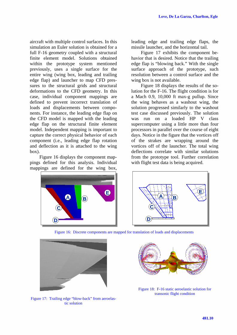
aircraft with multiple control surfaces. In thissimulation an Euler solution is obtained for afull F-16 geometry coupled with a structuralfinite element model. Solutions obtainedwithin the prototype system mentionedpreviously, uses a single surface for theentire wing (wing box, leading and trailingedge flap) and launcher to map CFD pres-sures to the structural grids and structuraldeformations to the CFD geometry. In thiscase, individual component mappings aredefined to prevent incorrect translation ofloads and displacements between compo-nents. For instance, the leading edge flap onthe CFD model is mapped with the leadingedge flap on the structural finite elementmodel. Independent mapping is important tocapture the correct physical behavior of eachcomponent (i.e., leading edge flap rotationand deflection as it is attached to the wingbox).
Figure 16 displays the component map-pings defined for this analysis. Individualmappings are defined for the wing box,
leading edge and trailing edge flaps, themissile launcher, and the horizontal tail.
Figure 17 exhibits the component be-havior that is desired. Notice that the trailingedge flap is “blowing back.” With the singlesurface approach of the prototype, suchresolution between a control surface and thewing box is not available.
Figure 18 displays the results of the so-lution for the F-16. The flight condition is fora Mach 0.9, 10,000 ft max-g pullup. Sincethe wing behaves as a washout wing, thesolution progressed similarly to the washouttest case discussed previously. The solutionwas run on a loaded HP V classsupercomputer using a little more than fourprocessors in parallel over the course of eightdays. Notice in the figure that the vortices offof the strakes are wrapping around thevortices off of the launcher. The total wingdeflections correlate with similar solutionsfrom the prototype tool. Further correlationwith flight test data is being acquired.
CC
AA BB
DD
EEAA BB
CC
DD
EE
Figure 16: Discrete components are mapped for translation of loads and displacements
Figure 17: Trailing edge “blow-back” from aeroelas-tic solution
Figure 18: F-16 static aeroelastic solution fortransonic flight condition

COMPUTATIONAL AEROELASTICITY IN HIGH PERFORMANCE AIRCRAFT FLIGHT LOADS
481.11
6 Summary
A new method for computational aeroelasticanalysis is presented that provides for timelyanalysis for complex geometry. The pre-sented technique uses a Cartesian gridscheme that allows the mesh to be automati-cally generated and adapted in each aero-elastic iteration. The solution scheme movesthe geometry facets through the Cartesianmesh at each aeroelastic iteration as opposedto common methods where the entire mesh isdeflected to accommodate the deformedvehicle geometry. The presented schemeprovides an alternate method for computingstatic aeroelastic pressures that can be usedin development of critical flight loads.Studies have shown a requirement forcontinued development and validation of aviscous capability. Current efforts arefocused in this area.
References
[1] Siegel J M, Jr., et al. Application of a Multi-Disciplinary Computing Environment (MDICE)for loosely coupled fluid-structural analysis. Pre-sented at the 7th AIAA/USAF/NASA/ISSMOSymposium of MDO, AIAA 98-4866, September1998.
[2] Karman S L Jr. SPLITFLOW: 3d unstructuredcartesian/prismatic grid CFD code for complexgeometries. American Institute of Aeronauticsand Astronautics Paper, AIAA-95-0343.
[3] Love Michael H, et al. Enhanced maneuverairloads simulation for the automated structuraloptimization system, ASTROS. American Insti-tute of Aeronautics and Astronautics Paper,AIAA-97-1116.
[4] Neill D J, and Sikes G. The MSC Flight LoadsSystem. MSC Aerospace User’s Conference, No-vember 1997.
[5] Luker Joel J, Huttsell Lawrence J. Air ForceResearch Laboratory’s progress in fluids-structures interaction. American Institute ofAeronautics and Astronautics Paper, AIAA-98-2420.
[6] Bennett Robert M, Edwards John W. Anoverview of recent developments in computa-tional aeroelasticity. American Institute of Aero-nautics and Astronautics Paper, AIAA-98-2421.
[7] Hartwich Peter M, and Agrawal Shreekant.Method for perturbing multiblock patched gridsin aeroelastic and design optimization applica-
tions. American Institute of Aeronautics and As-tronautics Paper, AIAA 97-2038.
[8] Lee-Rausch Elizabeth M, and Batina John T.Calculations of AGARD wing 445.6 flutter usingNavier-Stokes aerodynamics. Presented at theAmerican Institute of Aeronautics and Astronau-tics 11th Applied Aerodynamics Conference,AIAA 93-0001, August 9-11, 1993.
[9] Schuster D, Vadyak J, and Atta E. Staticaeroelastic analysis of fighter aircraft using athree-dimensional Navier-Stokes algorithm. Pre-sented at the 28th American Institute of Aeronau-tics and Astronautics Aerospace Sciences Meet-ing, AIAA 90-0435.
[10] Guruswamy G P, Byun C. Fluid-structuralinteractions using Navier-Stokes flow equationscoupled with shell finite element structures. Pre-sented at the 24th American Institute of Aeronau-tics and Astronautics Fluid Dynamics Confer-ence, AIAA 93-3087, July 6-9, 1993.
[11] Farhat Charbel. High performance simulation ofcoupled nonlinear transient aeroelastic problems.Parallel Computing in CFD, AGARD-R-807,October 1995.
[12] Brown S A. Displacement extrapolations forCFD+CSM aeroelastic analysis. American Insti-tute of Aeronautics and Astronautics Paper AIAA97-1090, 1997.
[13] Rogers W A, et al. Validation of aeroelastictailoring by static aeroelastic and flutter tests.AFWAL-TR-81-3160, September 1982.