computation of light scattering by anisotropic spheres of...
TRANSCRIPT
Research News
Computation of Light Scattering byAnisotropic Spheres of Rutile Titania**
By Erik S. Thiele and Roger H. French*
1. Introduction
Rutile titania offers an attractive combination of physicalproperties that has made it the most widely used whitepigment in the worldwide marketplace for coatings, plastics,and paper.[1,2] A fundamental goal of both consumers andmanufacturers of rutile titania pigment is to maximize thelight scattering efficiency of the pigment in end use.Achieving this goal depends upon identifying, and subse-quently controlling, the factors that affect the light scatteringefficiency of rutile titania powders. These factors include theparticle size distribution, the degree of particle agglomera-tion, and the degree of optical interaction between neighbor-ing particles in a microstructure. However, the quantitativeinfluence of each of these factors upon the hiding power ofrutile titania is not fully understood, due in large part to thedifficulty of controlling laboratory experiments to the degreethat the effect of each can be studied independently.[3] In thestudy described here, we applied a finite element methodthat produces rigorous full-field solutions to Maxwell'sequations to the problem of light scattering by anisotropicrutile titania spheres.
Owing to the inherent experimental challenges, theoret-ical modeling has been used to understand light scatteringproperties of rutile titania. These efforts have typically reliedupon Mie theory, which provides an exact treatment of thelight scattering properties of a single, optically isotropicsphere.[4±6] Such studies have included investigation of thetheoretical hiding power of rutile titania versus that of airvoids,[7] the crowding effect in highly loaded films,[8] and theapplication of a multiple scattering model to predict the lightscattering efficiency of paint films.[9] Mie theory has alsobeen used to study the light scattering properties of core±shell composite particles containing inorganic coatings.[10] Inreality, individual rutile titania particles exhibit both opticalanisotropy and complex shapes. Mie theory is therefore not
capable of rigorously describing the light scattering proper-ties of realistic rutile titania particle shapes and microstruc-tures. Recently, Thiele and French[11,12] have reported finiteelement computations on the light scattering properties ofanisotropic, morphological rutile titania particles.
Attempts to use Mie theory to predict the light scatteringproperties of a rutile titania particle require approximationto address the optical anisotropy of the crystal. Rutile titaniais uniaxial, exhibiting its ordinary refractive index for lightpolarized parallel to either the a- or b-axis of the crystal andits extraordinary refractive index for light polarized parallelto the c-axis. Two methods for approximating rutile usingisotropic materials have been proposed in the literature. Oneapproach has been to compute the mean of the refractiveindices along the three crystal axes at the light wavelength ofinterest and subsequently apply Mie theory to compute far-field scattering parameters.[9] We refer to this as the averageindex approximation. Another method has been to computeseparately the far-field scattering parameters for an isotropicsphere having the ordinary and extraordinary refractiveindices of rutile titania, and subsequently compute theweighted sum of these separate far-field results.[7,9] Theweighted sum consists of two-thirds the result for theordinary refractive index plus one-third the result for theextraordinary refractive index. We refer to this as theweighted sum approximation.
In the present study, we employ a finite element method tocompute the near- and far-field scattering properties ofoptically anisotropic spheres of rutile titania at the wave-length of 560 nm. These results were then compared toresults obtained using Mie theory under both the averageindex and weighted sum approximations. The finite elementmethod produces rigorous solutions to Maxwell's equationsfor electromagnetic radiation interacting with arbitrarymicrostructures, which can contain optically anisotropicmaterials. The finite element approach can therefore be usedto determine the light scattering properties of realisticsystems that would otherwise be inaccessible. In the case oflight scattering by an optically anisotropic sphere, resultsobtained using the finite element method contain the effectsof the optical activity of the uniaxial crystal, unlike the resultsof either of the two aforementioned approximations basedupon scattering by isotropic spheres.
Adv. Mater. 1998, 10, No. 15 Ó WILEY-VCH Verlag GmbH, D-69469 Weinheim, 1998 0935-9648/98/1510-1271 $ 17.50+.50/0 1271
±
[*] Dr. R. H. French, Dr. E. S. ThieleDuPont Central Research and DevelopmentExperimental StationPO Box 80356, Wilmington, DE 19880-0356 (USA)
[**] The authors thank J. Mould, Jr. for computational support inimplementing the finite element code.
1272 Ó WILEY-VCH Verlag GmbH, D-69469 Weinheim, 1998 0935-9648/98/1510-1272 $ 17.50+.50/0 Adv. Mater. 1998, 10, No. 15
2. Computational Approach
2.1. Finite Element Method
A review of the finite element method for the computationof electromagnetic radiation scattering is available in theliterature.[13] Briefly, the method is based upon piecewisesolution of the time domain form of Maxwell's equations insource-free space given in Equation 1, where the computa-tional domain is discretized into a finite number of volumeelements. Here, E is electric field amplitude, e the electricpermittivity of the medium, and m the magnetic permeabilityof the medium. The finite element method is a generalformulation that can be applied in diverse electromagneticapplications.[14,15]
Ñ2 E ± em@2E@t2� 0 (1)
The finite element models in the present study areconstructed in a Cartesian coordinate system by specifyingedge dimensions, the finite element mesh density, particleposition(s) and shape(s), and the optical properties of theconstituent materials at the wavelength of interest. Typicalmodels contain ~2 million elements. Electromagnetic radia-tion is allowed to propagate within the finite element modelin the time domain, with electric field amplitude and phasecomputed at each node in the finite element model at eachtime step. A sufficient number of time steps are executed in acomputation to ensure that steady state is achieved. Thescattered electric field at near field is extrapolated onto thesurface of a far-field sphere having a radius that is very largecompared to the wavelength of the radiation. The simulationof diffuse illumination is accomplished by superimposing thefar-field scattered intensities computed in a series ofindividual computations in which the illumination directionsare varied step-wise over the necessary range of orientations.
After extrapolation of the scattered electric field andintensities has been accomplished, it is straightforward toextract macroscopically observable physical quantities suchas the scattering cross section Csca of the microstructurebeing modeled and the angular distribution of scattered light.The scattering cross section is defined in Equation 2 and isexpressed in units of area, where y is the scattering angle, I0
the incident radiation intensity, and Isca(y) the scatteredintensity on the surface of a far-field sphere over which thesurface integral is performed.
Csca =1I0
RR4p
Isca�y�dO (2)
It is instructive to normalize the scattering cross section bythe volume of the scattering material in the finite elementmodel. The scattering coefficient S is defined in Equation 3and is expressed in dimensions of inverse length.
S = Csca/V (3)
The scattering coefficient S provides information aboutthe strength of light scattering by a particular microstructureon a per-volume basis. It provides no direct information,however, about the efficiency of a microstructure indeflecting light away from the direction of incidence; in apaint film, for example, a combination of strong scatteringper volume and strong deflection of light is desired, since it isthis combination that imparts hiding power. The asymmetryparameter g (Eq. 4) is the average cosine of the scatteringangle associated with a scattering microstructure, weightedby the scattered intensity as a function of scattering angle.
g �RR4p
I�y� cos ydyRR4p
I�y�dy (4)
The asymmetry parameter g is dimensionless and variesbetween ±1 (for perfect backwards scattering) and 1 (forperfect forward scattering). Both the asymmetry parameterand the scattering coefficient play prominent roles inmultiple scattering theory, where the term defined here asthe angle-weighted scattering coefficient s (Eq. 5) expressesthe combined ability of a scattering feature to stronglydeflect incident electromagnetic radiation away from thedirection of incidence.[16]
s = S (1±g) (5)
The angle-weighted scattering coefficient s, like thescattering coefficient S, has dimensions of inverse length. Itcan be considered a figure of merit in the context of theability of a scattering feature in a paint film to contribute tohiding power. Throughout this article, scattering results areexpressed in terms of both the scattering coefficient S and theangle-weighted scattering coefficient s.
2.2. Mie Theory
To quantify the accuracy of the finite element method, it isuseful to compare results obtained using the finite elementmethod for scattering by an isotropic sphere to the exactresults obtained using Mie theory. To compute the Mietheory results presented below, we have employed theBHMIE computer code provided by Bohren and Huffman,[6]
with additional code introduced for computation of theasymmetry parameter. In this computational approach,series expansions are performed to compute the scatteringcross section and asymmetry parameter at far field.
3. Scattering by Single Anisotropic Spheres
The light scattering properties of thirteen anisotropic,high-index spheres having the optical constants of rutiletitania have been computed using the finite element method.The light wavelength used in these computations is 560 nm,the center of the visible spectrum. At this wavelength, the
Research News
ordinary refractive index of rutile titania has been reportedas 2.64, while the extraordinary index has been reported as2.94.[17] The physical symmetry elements of an anisotropic,uniaxial sphere include an equatorial mirror plane and acylindrical rotation axis perpendicular to this mirror plane.(In this description, the optic axis intersects the surface of thesphere at the two poles.) The complete light scatteringbehavior of such a system can therefore be sampled througha series of illuminations along any arc connecting one pole ofthe sphere to the equator. We use six different illuminationdirections for each sphere at the evenly spaced angles 7.5�,22.5�, 37.5�, 52.5�, 67.5�, and 82.5� relative to the optic axis.Two mutually perpendicular polarizations (parallel andperpendicular to the optic axis of the sphere) are used foreach illumination direction, resulting in a total of 12individual illuminations per sphere. The far-field scatteringparameters S and s are computed for each sphere bycomputing the averages of these two quantities, weightingthe individual results by the probabilities of occurrenceassociated with each of the illumination directions; under
conditions of random illumination, illumination directionsnearly perpendicular to the optic axis are more probable thanthose nearly parallel to the optic axis.
The finite element models for each of the spheres studiedconsisted of a spherical particle at the center of a cubic finiteelement model. In each case, the sphere is surrounded by anoptically isotropic medium with refractive index n = 1.514,representative of an acrylic resin.[7] The finite element meshdensity differs from model to model but is typically 50±60elements per wavelength in the highest index material in themodel. In the case of the 0.2 mm sphere, for example, thecubic element edge length is 3.87 nm. In general, finer finiteelement meshes lead to improved accuracy. Previousaccuracy analysis of this finite element approach[11,12]
suggests that the error associated with each of the calcula-tions in this study should be less than 2 %.
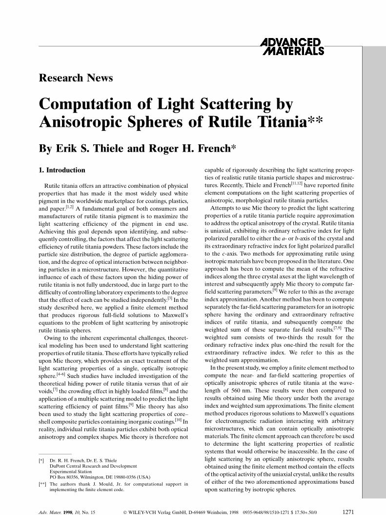
The full near-field results of a finite element computationperformed on the 0.2 mm anisotropic sphere are shown inFigure 1. The upper left panel of the figure shows a three-dimensional view of the sphere (with the surrounding
Adv. Mater. 1998, 10, No. 15 Ó WILEY-VCH Verlag GmbH, D-69469 Weinheim, 1998 0935-9648/98/1510-1273 $ 17.50+.50/0 1273
Research News
Fig. 1. Finite element model and scatteredintensities for a 0.2 mm anisotropic sphere ofrutile titania. The 560 nm radiation prop-agates in the +x direction, with unit incidentintensity. Polarization is parallel to the ydirection.
1274 Ó WILEY-VCH Verlag GmbH, D-69469 Weinheim, 1998 0935-9648/98/1510-1274 $ 17.50+.50/0 Adv. Mater. 1998, 10, No. 15
medium removed for clarity), and the upper right panelshows a cross-sectional view through the center of the finiteelement model. The lower two panels show steady-statescattered intensities in the views corresponding to the twopanels above. In this computation, the 560 nm incident lightpropagates in the finite element model in the +x direction,and the incident polarization is parallel to the y direction.The incident intensity of the light is equal to unity. In both ofthe lower panels of Figure 1, the scattered intensities in themodel are as much as 4.3 times greater than the incidentintensity. This concentration of scattered light in the vicinityof the particles is characteristic of scattering of electro-magnetic radiation by highly resonant features.
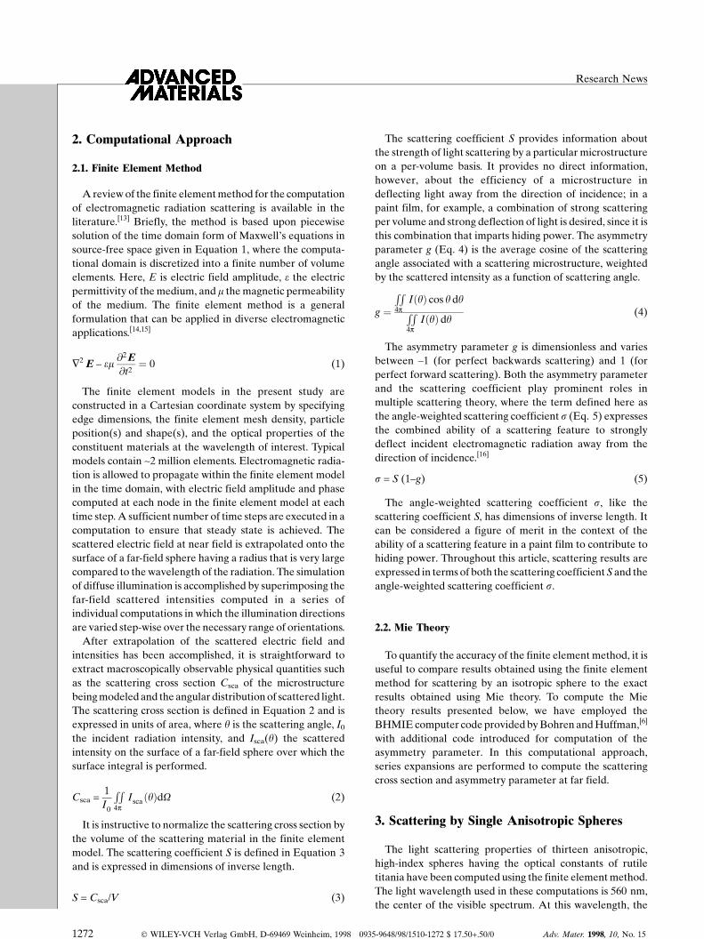
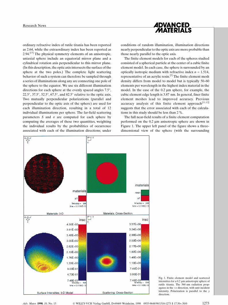
Using the methodology described above, the far-fieldparameters S and s have been computed for a series ofanisotropic spheres of rutile titania with diameters in therange 0.05±0.35 mm. Results for the scattering coefficient Sare summarized in Table 1 and plotted versus spherediameter in Figure 2 (filled circles). These data exhibit asharp increase in S as the sphere diameter is increased from0.05 to 0.2 mm, beyond which resonant peaks are observed asthe diameter is further increased. Results for the angle-weighted scattering coefficient s are also summarized inTable 1 and plotted versus sphere diameter in Figure 3
(filled circles). These data exhibit the same sharp increase ins as the sphere diameter increases from 0.05 to 0.2 mm, in aqualitative sense, as the S results in Figure 2. For spherediameters greater than 0.2 mm, the s data in Figure 3decrease without the same pronounced resonant peaksobserved in the S data.
4. Discussion
4.1. Angle and Polarization Dependence of Scattering byan Anisotropic Sphere
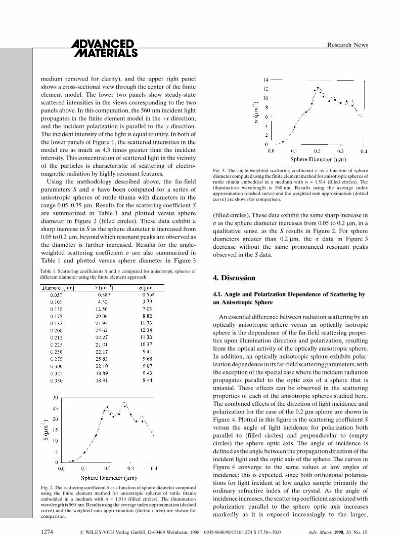
An essential difference between radiation scattering by anoptically anisotropic sphere versus an optically isotropicsphere is the dependence of the far-field scattering proper-ties upon illumination direction and polarization, resultingfrom the optical activity of the optically anisotropic sphere.In addition, an optically anisotropic sphere exhibits polar-ization dependence in its far-field scattering parameters, withthe exception of the special case where the incident radiationpropagates parallel to the optic axis of a sphere that isuniaxial. These effects can be observed in the scatteringproperties of each of the anisotropic spheres studied here.The combined effects of the direction of light incidence andpolarization for the case of the 0.2 mm sphere are shown inFigure 4. Plotted in this figure is the scattering coefficient Sversus the angle of light incidence for polarization bothparallel to (filled circles) and perpendicular to (emptycircles) the sphere optic axis. The angle of incidence isdefined as the angle between the propagation direction of theincident light and the optic axis of the sphere. The curves inFigure 4 converge to the same values at low angles ofincidence; this is expected, since both orthogonal polariza-tions for light incident at low angles sample primarily theordinary refractive index of the crystal. As the angle ofincidence increases, the scattering coefficient associated withpolarization parallel to the sphere optic axis increasesmarkedly as it is exposed increasingly to the larger,
Research News
Table 1. Scattering coefficients S and s computed for anisotropic spheres ofdifferent diameter using the finite element approach.
Fig. 2. The scattering coefficient S as a function of sphere diameter computedusing the finite element method for anisotropic spheres of rutile titaniaembedded in a medium with n = 1.514 (filled circles). The illuminationwavelength is 560 nm. Results using the average index approximation (dashedcurve) and the weighted sum approximation (dotted curve) are shown forcomparison.
Fig. 3. The angle-weighted scattering coefficient s as a function of spherediameter computed using the finite element method for anisotropic spheres ofrutile titania embedded in a medium with n = 1.514 (filled circles). Theillumination wavelength is 560 nm. Results using the average indexapproximation (dashed curve) and the weighted sum approximation (dottedcurve) are shown for comparison.

extraordinary index of the rutile crystal. For polarizationperpendicular to the optic axis, however, no component ofthe incident light is exposed to the extraordinary refractiveindex of the crystal, resulting in no dependence of S upon theangle of incidence. In Figure 4, the scattering coefficient Sfor unpolarized light incident from any of the angles showncan be computed by averaging the values associated with thetwo orthogonal polarizations.
Fig. 4. Scattering coefficient S as a function of the angle of incidence of thelight (relative to the optic axis) for a 0.2 mm anisotropic sphere of rutile titania.Empty circles are for polarization perpendicular to the optic axis of the sphere;filled circles are for polarization coplanar with the optic axis. These resultswere computed using the finite element method.
4.2. The Validity of the Average Index and Weighted SumApproximations
A question of central interest in this study is to what degreethe average index and weighted sum approximationsdescribed in Section 1 succeed in predicting the far-fieldscattering parameters associated with the anisotropicspheres investigated here.
The agreement in the scattering coefficient S between theresults computed using the finite element method and boththe average index (dashed curve) and the weighted sum(dotted curve) approximations is shown in Figure 2. In bothcases, agreement between the finite element method resultsfor anisotropic spheres and the approximate approaches isexcellent for diameters 0.18 mm and smaller. The weightedsum approximation underestimates the first resonant peak inthe finite element results (0.2 mm sphere), but the averageindex approximation accurately matches this peak value. Fordiameters greater than 0.2 mm, differences of up to 10 %occur between the two approximations and the finiteelement results. The three data sets in Figure 2 suggest thatthe periodicity of the resonant peaks in the finite elementresults is longer than in either of the two approximations. Ithas been suggested that such resonant peaks arise fromresonant surface waves on a sphere;[5] it is thereforereasonable that the different symmetry of an anisotropicsphere compared to an isotropic should result in aquantitatively different behavior of such resonances. It isnot immediately clear why the period of the resonant peaks
associated with anisotropic spheres is longer than either ofthe two approximations based upon isotropic spheres.Comparison of the average index and weighted sumapproximation data sets in Figure 2 indicate that the maindifference between the two is that the resonant peaks in theweighted sum approximation are less sharp. That approx-imation is a weighted superposition of two curves that areslightly offset with respect to sphere diameter, resulting inaveraging of the resonant peaks.
The agreement of the angle-weighted scattering coeffi-cient s between the finite element method and both theaverage index (dashed curve) and weighted sum (dottedcurve) approximations is shown in Figure 3. In analogy withresults for the scattering coefficient S in Figure 2, agreementbetween the finite element data and both approximations isvery good for diameters less than 0.18 mm. For spherediameters greater than this value, the data sets contain thesame resonant features, with the period of the resonant peaksfor the finite element data again being greater than that ofthe average index approximation. In both S and s, themaximum values in the average index approximation(sphere diameter ~0.2 mm) are in very good agreement withthe finite element data. The most significant disagreementbetween the weighted sum approximation and the finiteelement data occurs around the primary resonant peak,around 0.2 mm. The average index approximation moreaccurately fits this first resonant peak than the weighted sumapproximation in both S and s.
The statistical quantity w2 has been computed as a means ofquantifying the ability of both the average index andweighted sum approximations to predict the results for Sand s of anisotropic spheres obtained using the finiteelement method. The complete data sets in Figures 2 and 3were used. The quantity s2 has been computed usingEquation 6, where n is the number of data points (thirteen,in this case), Ok is the value of S or s computed for a givensphere diameter using either the average index or weightedsum approximations, and Ek is the value of S or s computedfor the sphere diameter using the finite element method.
w2 �Pn
k�1
�OkÿEk�2
Ek
(6)
The values of w2 computed for the average index andweighted sum approximations are summarized in Table 2 forboth quantities S ands. The value of w2 is significantly smallerthan the number of data points for each data set, indicating avery good statistical fit in each case. For both S and s, theweighted sum approximation exhibits slightly lower w2 values
Adv. Mater. 1998, 10, No. 15 Ó WILEY-VCH Verlag GmbH, D-69469 Weinheim, 1998 0935-9648/98/1510-1275 $ 17.50+.50/0 1275
Research News
Table 2. Values of w2 (Eq. 6) associated with S and s values for the averageindex and weighted sum approximations, compared to anisotropic spherescattering data generated using the finite element approach.
1276 Ó WILEY-VCH Verlag GmbH, D-69469 Weinheim, 1998 0935-9648/98/1510-1276 $ 17.50+.50/0 Adv. Mater. 1998, 10, No. 15
than the weighted sum approach, but this can be reversed byselectively omitting certain discrete data points from the datasets, indicating no clear advantage to either approach from astatistical standpoint.
While both the average index and weighted sum approx-imations are in good statistical agreement with the results offinite element computations for anisotropic spheres, thereare possible advantages associated with each for a givencircumstance. The average index approximation offers theadvantage of explicitly defining a single refractive index forthe material, therefore requiring only a single set ofcomputations to obtain far-field results. The weighted sumapproximation offers the advantage of smoothing out thesharp resonant peaks associated with particular spherediameters in Mie theory computations, artifacts of the highsymmetry of a sphere that in practice are not observed inlight scattering by real systems of multiple particles.
5. Conclusions
Efforts to model the light scattering properties of rutiletitania have typically relied upon Mie theory, which is limitedto the description of a single, isotropic sphere. This approachrequires simplifying approximations to address the opticalanisotropy of the particles. In the study described here, weapplied a finite element method that produces rigoroussolutions to Maxwell's equations to the problem of lightscattering by anisotropic rutile titania spheres. We observedresonances in the far-field scattering coefficients that dependupon sphere diameter, in analogy with approximations basedon Mie theory. The far-field scattering coefficient dependsupon both the angle of incidence of light and the
polarization. For a 0.2 mm sphere, we observe that polariza-tion parallel to the optic axis of the sphere results in largerscattering coefficients than the perpendicular polarization.This is consistent with the fact that the extraordinaryrefractive index of the crystal is greater than the ordinaryat the 560 nm wavelength studied. The results of thisnumerical approach are compared to the two usual Mietheory approximations used to address the anisotropy ofrutile titania. Both approximations are in good statisticalagreement with the finite element results, although theperiod of the resonant peaks for anisotropic spheres is longerthan in either of the approximations.
±[1] J. H. Braun, A. Baidins, R. E. Marganski, Prog. Org. Coat. 1992, 20, 105.[2] T. C. Patton, Pigment Handbook, Wiley, New York 1973.[3] D. P. Fields, R. J. Buchacek, J. G. Dickinson, J. Oil Colour Chem. Assoc.
1993, 2, 87.[4] G. Mie, Ann. Phys. (Leipzig) 1908, 25, 377.[5] H. C. van de Hulst, Light Scattering by Small Particles, Dover, New York
1981.[6] C. F. Bohren, D. R. Huffman, Absorption and Scattering of Light by
Small Particles, Wiley-Interscience, New York 1983.[7] W. D. Ross, J. Paint Technol. 1971, 43, 50.[8] S. Fitzwater, J. W. Hook III, J. Coat. Technol. 1985, 57, 39.[9] B. R. Palmer, P. Stamatakis, C. F. Bohren, G. C. Salzman, J. Coat.
Technol. 1989, 61, 41.[10] R. W. Johnson, E. S. Thiele, R. H. French, TAPPI J. 1997, 80, 233.[11] E. S. Thiele, R. H. French, J. Am. Ceram. Soc. 1998, 81, 469.[12] E. S. Thiele, R. H. French, in Proc. of the 4th Nürnberg Congress of the
Paint Research Association, Paint Research Association, Teddington,UK 1997.
[13] J. L. Volakis, A. Chatterjee, L. C. Kempel, J. Opt. Soc. Am. A 1994, 11,1422.
[14] G. L. Wojcik, J. Mould, L. West, in Integrated Photonics Research 1993,Technical Digest Series, Vol. 10, Optical Society of America, Washing-ton, DC 1993.
[15] G. L. Wojcik, D. K. Vaughan, L. K. Galbraith, Proc. SPIE 1987, 774, 21.[16] C. F. Bohren, Am. J. Phys. 1987, 55, 524.[17] M. W. Ribarsky, Handbook of Optical Constants (Ed: E. D. Palik),
Academic, New York 1985.
Research News
_______________________