compressive strength of micropile-to-grout connectionscristina/rrest/aulas_apresentacoes/07... ·...
TRANSCRIPT

Construction and Building Materials 26 (2012) 172–179
Contents lists available at ScienceDirect
Construction and Building Materials
journal homepage: www.elsevier .com/locate /conbui ldmat
Compressive strength of micropile-to-grout connections
J. Veludo a, E.N.B.S. Júlio b,⇑, D. Dias-da-Costa c
a ICIST, Department of Civil Engineering, Polytechnic Institute of Leiria, Campus 2, Morro do Lena, Alto do Vieiro, 2411-901 Leiria, Portugalb ICIST, Department of Civil Engineering, Instituto Superior Técnico, Technical University of Lisbon, Lisbon, Portugalc INESCC, Department of Civil Engineering, University of Coimbra, Coimbra, Portugal
a r t i c l e i n f o a b s t r a c t
Article history:Received 28 October 2010Received in revised form 10 May 2011Accepted 13 June 2011Available online 12 July 2011
Keywords:BondStrengthConfinementRetrofittingInterfaceMicropileGroutPush-off tests
0950-0618/$ - see front matter � 2011 Elsevier Ltd. Adoi:10.1016/j.conbuildmat.2011.06.007
⇑ Corresponding author. Tel.: +351 218 418 258; faE-mail addresses: [email protected] (J. V
(E.N.B.S. Júlio), [email protected] (D. Dias-da-Costa).
Strengthening foundations with micropiles is progressively being used, due to the major advantages thatthis technique presents. Nevertheless, the influence of some relevant parameters in the overall behaviorof the retrofitted foundations has not yet been studied. Generally, micropiles are installed in holes drilledthrough the existing RC footing, which are then filled with grout. The efficiency of the load transfer mech-anism depends on the bond strength of both the micropile–grout and the concrete–grout interfaces.
This paper describes an experimental study performed to specifically study the influence of the follow-ing parameters on the bond strength between micropile–grout interface: hole diameter; embedmentlength of the micropile; and level of confinement of the grout mass. Thirty micropile–grout specimenswere submitted to monotonic push-off tests, until failure. Bond strength was found to increase with adecrease of the hole diameter and with an increase of the confinement level.
� 2011 Elsevier Ltd. All rights reserved.
1. Introduction
RC footing strengthened with steel micropiles is today a wide-spread method. However, in practice, it is empirically applied. Inreality, although the parameters that influence the connectioncapacity are identified, these have not been quantified in a compre-hensive way. In general, micropiles are applied to the existing RCfootings through predrilled holes. After the micropile is installed,the hole is filled with non-shrink grout. It is known that the effi-ciency of the connection depends on the bond strength of boththe micropile–grout and the grout–concrete interfaces but thishas not been characterized so far.
To increase the bond strength of the micropile–grout interface,it is common practice to weld steel rings or a steel spiral aroundthe perimeter of the casing. To improve the bond strength of thegrout–concrete interface, sometimes grooves are chipped into thewall of the hole. Detailing depends mainly on the required capacity[1–3]. Attention must also be paid to the reinforcement of theexisting concrete footing since this can be inadequate for thestrengthened situation. In this case, the lateral and the axial con-finement of the existing footing should be increased to improvethe connection capacity.
ll rights reserved.
x: +351 218 497 650.eludo), [email protected]
As mentioned, few experimental studies have been conductedon this subject. Gómez et al. [4] performed push-off tests to studythe connection capacity of smooth micropiles, grouted in rein-forced concrete footings through holes drilled using a jack ham-mer. The authors concluded that the connection capacity iscontrolled by adhesion and friction at the micropile–grout inter-face and that the residual capacity of the connection is entirely fric-tional and dependent on the confinement provided by the footingreinforcement. It is also concluded that the connection capacity in-creases with the decrease of the hole diameter and that the embed-ment length has little influence on the bond strength.
Contrarily to micropile–footing connections, the bond mecha-nism between reinforcing bars and concrete is well studied andit is generally accepted that it is controlled mainly by three differ-ent parameters: (1) chemical adhesion between concrete and steel;(2) friction between concrete and steel; and (3) bearing of the rebarribs on the surrounding concrete [5–8]. Two different bond failuremechanisms can be observed: splitting failure or pull-out failure.
Various studies have also been performed in grouted ribbed re-bar or cable bolts. Moosavi et al. [9] studied the bond of cementgrouted reinforcing bars under constant radial pressure. Theseauthors state that the properties of both grout and confinementplay an important role in developing the bond capacity.
Hyett et al. [10] performed several pull-out tests of groutedcable bolts using a modified Hoek cell and concluded that the bondstrength at the cable bolt–grout interface is more related to frictionrather than to chemical adhesion. The authors also state that the

32.5
53.4
Unc
onfin
ed C
ompr
essi
ve S
treng
th,
fcm
(MPa
)
0 14 28 42 56 70 84 98 112
Concrete Grout0
10
20
30
40
50
60
70
J. Veludo et al. / Construction and Building Materials 26 (2012) 172–179 173
bond strength depends on the pressure generated at the cablebolt–grout interface caused by dilatancy during bond failure. In aprevious study, Hyett et al. [11] indicate that the parameters witha major influence in cable bolt capacity are: the grout properties(w/c ratio); the cable bolt embedment length; and the radial con-finement acting on the outer surface of the grout mass. Yahiaet al. [12] studied the bond strength of cement grout anchors castin rock under dry and submerged conditions. These authors con-cluded that the main mechanism to mobilize the bond strengthis the friction developed at both grout–rebar and grout–rock inter-faces. It is also concluded that friction depends on: the mechanicalproperties of both rock and grout; the geometry of the hole and ofthe bar; and the roughness of the drilled hole surface. Malvar [13]and Noghabai [14] performed pull-out tests with deformed barscast in concrete cylinders under different radial confinements. Bothauthors conclude that the confinement is the most important fac-tor at the slip phase and observed the increase of bond stress withthe growth of the level of confinement.
From the studies previously referred to, it can be assumed thatthe load transfer mechanism between a strengthening steel micro-pile and the existing reinforced concrete footing is controlled bythree different parameters: (1) chemical adhesion at the steel–grout and the grout–concrete interfaces; (2) friction at the steel–grout and the grout–concrete interfaces; and (3) bearing of thewelded steel rings/spirals at the steel–grout interface and of theconcrete grooves at the grout–concrete interface.
Design codes for RC structures, namely ACI 318 [15], EuroCode 2[16] and the CEB-FIP ModelCode 1990 [6], specify expressions forthe design of the bond strength and development length of barsembedded in concrete. However, none of these codes presentsexpressions to compute the development and the bond stress ofbars grouted in holes predrilled in concrete. Furthermore, usingcurrent codes expressions to determine the development lengthof a smooth micropile in a predrilled hole filled with grout wouldbe too conservative. Moreover, this would require having a signif-icantly deep foundation, which is not observed in practice.
The study herein described focuses specifically the behavior ofthe steel–grout interface with smooth micropile inserts aiming toquantify the influence of the following parameters: the hole diam-eter, the embedment length; and the confinement of the groutmass.
Curing Time (days)
35.2
14.0
´s M
odul
us, E
cm (
GPa
)
15
20
25
30
35
40
45
(a)
2. Research significanceStrengthening existing RC footings with grouted steel micro-piles is currently one of the most used retrofitting techniques offoundations. However, in practice, this is performed empiricallysince the behavior of the micropile–footing connection has notbeen characterized so far. The experimental study herein describedcontributes to the knowledge of the behavior of the micropile–grout interface. It is demonstrated that: the capacity of themicropile–footing connection increases with the decrease ofthe hole diameter; and the bond strength strongly depends onthe radial confinement; but it is not significantly influencedby the insert embedment length.
0 14 28 42 56 70 84 98 112
Curing Time (days)
Youn
g
Concrete Grout0
5
10
(b)Fig. 1. Mechanical properties of concrete and grout: (a) unconfined compressivestrength and (b) Young’s modulus.
3. Experimental investigation
Aiming to study the influence of the insert embedment length, the hole diam-eter and the confinement of the grout mass, 15 different situations were definedand, for each one, two specimens were tested in compression. In order to enable dif-ferent radial confinement levels of the grout mass, steel tubes, PVC tubes and RCblocks were used. First, 30 smooth inserts were positioned inside 10 steel tubes,10 PVC tubes and 10 holes predrilled in RC footings. Then, an unreinforced massof grout was used to seal the void between the inserts and the walls of thetubes/holes. Afterwards, these specimens were tested in compression until failure,to evaluate the influence of the parameters referred to on the bond strength of the
micropile–grout interface. Besides these, the remaining parameters were kept con-stant, such as: grout type and strength; concrete type and strength; micropile in-sert; and loading procedure. In the following paragraphs, the materials adoptedin this study, the different situations considered, the geometry adopted for thespecimens, the production of the specimens; and the tests set-up are described.
3.1. Materials
The micropile inserts were produced using smooth 60 mm API N80 steel tubegrade 562/703 MPa, with 6 mm thickness. In tests performed with concrete speci-mens, the tube was reinforced with a 16 mm grade 500/600 MPa bar which wasfirst welded to the center of a 150 � 150 � 20 mm3 steel plate. Finally, the insertwas fully grouted. An average roughness of 1 mm for the tube surface was mea-sured with a laser roughness analyzer [17].
A grout with a measured compressive strength of 53.4 MPa and a Young’s mod-ulus of 14.2 GPa, at 28 days, and a water–cement ratio of 0.40 was adopted. The mixproportions per cubic meter are the following: 1327 kg of type I:42.5 R Portland ce-ment, 530 l of water, 13.27 kg of modified polycarboxylate admixture (high rangewater reducer); and 13.27 kg of expansive admixture. At each age, a set composedby six specimens obtained from the flexure test performed on three prismatic spec-imens with 40 � 40 � 160 mm3 were used to evaluate the average compressivestrength at 1, 3, 7, 14, 21, 28, 56, and 90 days of age [18,19] (see Fig. 1a). Otherset composed by three prismatic specimens with the dimensions previously re-ferred to were used to evaluate the corresponding Young’s modulus [20] (seeFig. 1b). The specific gravity of the grout was 19.2 kN/m3. The following propertieswere measured, according to European standards [19]: a flowability of 11 s; a vol-ume change of 0%; a bleed of 0.45%; and an air content of 2%. These results wereconsidered acceptable, also according to European standards [21].
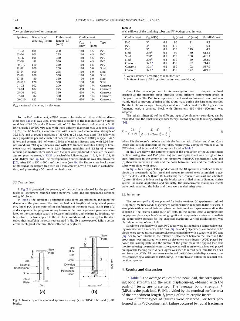
Table 1The complete push-off test program.
Specimen Diameter ofgrout (Dg) (mm)
Embedmentlength (Le)(mm)
Confinement
Dext
(mm)t(mm)
Type
P1-P2 101 200 110 4.5 PVCP3-P4 101 275 110 4.5 PVCP5-P6 101 350 110 4.5 PVCP7-P8 81 350 90 4.5 PVCP9-P10 119 350 130 5.5 PVCS1-S2 100 200 110 5.0 SteelS3-S4 100 275 110 5.0 SteelS5-S6 100 350 110 5.0 SteelS7-S8 80 350 90 5.0 SteelS9-S10 120 350 130 5.0 SteelC1-C2 102 200 450 174 ConcreteC3-C4 102 275 450 174 ConcreteC5-C6 102 350 450 174 ConcreteC7-C8 82 350 450 184 ConcreteC9-C10 122 350 450 164 Concrete
Dext – external diameter; t – thickness.
Table 2Wall stiffness of the confining tubes and RC footings used in tests.
Confinement Ecm (GPa) m do (mm) di (mm) Kr (MPa/mm)
PVC 3a 0.3 90 81 8.2PVC 3a 0.3 110 101 5.4PVC 3a 0.3 130 119 4.7Steel 200a 0.3 90 80 613.4Steel 200a 0.3 110 100 401.3Steel 200a 0.3 130 120 282.9Concrete 37.1b 0.2 450 82 714.8Concrete 37.1b 0.2 450 102 557.9Concrete 37.1b 0.2 450 122 449.7
a Values assumed according to manufacturer.b At time of tests (107 days after casting concrete blocks).
174 J. Veludo et al. / Construction and Building Materials 26 (2012) 172–179
For the PVC confinement, a PN10 pressure class tube with three different diam-eters (see Table 1) was used, presenting according to the manufacturer a Young’smodulus of 3.0 GPa and a Poisson ratio of 0.3. For the steel confinement, a St 52BK + S grade 520/600 MPa tube with three different diameters was used (see Table1). For the RC blocks, a concrete mix with a measured compressive strength of32.5 MPa and a Young’s modulus of 35 GPa, at 28 days, was used. The followingmix proportions per cubic meter of concrete were adopted: 280 kg of type II:42.5R Portland cement, 180 l of water, 250 kg of washed siliceous sand with 2.56 fine-ness modulus, 710 kg of siliceous sand with 3.71 fineness modulus, 880 kg of lime-stone crushed aggregates with 6.35 fineness modulus and 2.8 kg of a waterreducing admixture. Three cubes with 150 mm were produced to evaluate the aver-age compressive strength [22,23] at each of the following ages: 1, 3, 7, 14, 21, 28, 56and 90 days (see Fig. 1a). The corresponding Young’s modulus was also measured[20], using 150 � 150 � 600 mm3 specimens (see Fig. 1b). The concrete blocks werereinforced at the bottom face with an 8 mm S400 grid, with five bars in each direc-tion, and presenting a 50 mm of nominal cover.
3.2. Test specimens
In Fig. 2 is presented the geometry of the specimens adopted for the push-offtests: (a) specimens confined using steel/PVC tubes and (b) specimens confinedusing RC blocks.
In Table 1 the different 15 situations considered are presented, including thediameter of the grout mass, the insert embedment length, and the type and geom-etry (steel, PVC or concrete) of the confinement of the grout mass. This is part of awider experimental program aiming to assess the most significant parameters re-lated to the connection capacity between micropiles and existing RC footings. Forfew set-ups, the load applied to the RC blocks could exceed the strength of the steeltubes, thus justifying the rebar represented in Fig. 2b. Since expected failure occursat the steel–grout interface, their influence is neglected.
g
Le
D
Tube
DrillHole
DywidagBar
PolystireneInsert
150
mm
500
mm
450x450 mm2
SteelPlate
(a)
TubeExternal
Confinement
SteelPlate
Le
Dg
Grout
50 m
m
SteelPlate
Fig. 2. Geometry of the confined specimens using: (a) steel/PVC tubes and (b) RCblocks.
One of the main objectives of this investigation was to compare the bondstrength at the micropile–grout interface using different confinement levels ofthe grout mass. The PVC tube represents the lowest confinement level and wasmainly used to prevent splitting of the grout mass during the hardening process.The steel tube was adopted to apply a moderate confinement. For the highest con-finement level, a concrete block with dimensions 450 � 450 � 500 mm3 wasadopted.
The radial stiffness (Kr) of the different types of confinement considered can beestimated from the ‘thick wall cylinder theory’, according to the following equation[24]:
Kr ¼2E
ð1þ vÞ �d2
o � d2i
di � ð1� 2vÞ � d2i � d2
o
h i8<:
9=; ð1Þ
where E is the Young’s modulus and v is the Poisson ratio of tubes, and di and do areinside and outside diameters of the tubes, respectively. Computed values of Kr forPVC tubes, steel tubes and RC footings are listed in Table 2.
In Fig. 3 are shown the different stages of the production of the 20 specimensconfined using steel and PVC tubes: (a) each micropile insert was first glued to asteel formwork in the center of the respective steel/PVC confinement tube and(b) then, the micropile inserts and the holes between these and the confinementtubes were filled with grout.
In Fig. 4, four stages of the production of the 10 specimens confined with RCblocks are presented: (a) first, steel and wooden formwork were assembled to exe-cute the 450 � 450 � 500 mm3 RC blocks; (b) then, concrete was cast and vibrated;(c) after 28 days of indoor curing, the blocks were drilled using a diamond coringsystem for insert application and (d) lastly, the prefabricated micropiles insertswere positioned into the holes and these were sealed using grout.
3.3. Test set-up
The test set-up (Fig. 5) was planned for both situations: (a) specimens confinedusing steel/PVC tubes and (b) specimens confined using RC blocks. In the first case, asteel plate with a central hole was placed on bottom of each specimen to allow theslippage of the inserts during push-off tests. In the second case, a compressiblepolystyrene plate, capable of assuming significant compressive strains with negligi-ble compressive stresses for the expected maximum vertical displacement, wasplaced on bottom of each hole.
Specimens confined with steel/PVC tubes were tested using a compressive test-ing machine with a capacity of 60 tons (Fig. 6a and b). Specimens confined with RCblocks were tested using a compressive testing machine with a capacity of 500 tons(Fig. 6c). In both situations, the relative displacement between the insert and thegrout mass was measured with two displacement transducers (LVDT) placed be-tween the loading plate and the surface of the grout mass. The applied load wasmonitored using the machine pressure gauge as well as an external load cell placedon top of the loading plate. A data logger was used to record data from the load celland from the LVDTs. All tests were conducted until failure with displacement con-trol, considering a load rate of 0.025 mm/s, in order to also obtain the residual con-nection capacity.
4. Results and discussion
In Table 3, the average values of the peak load, the correspond-ing bond strength and the axial displacement, obtained with thepush-off tests, are presented. The average bond strength, fb
(MPa), is the peak load, Pu (N), divided by the nominal surface areaof the embedment length, lb (mm), of the micropile insert.
Two different types of failures were observed. For tests per-formed with PVC confinement, failure occurred by radial fracturing

Fig. 3. Production of specimens confined using steel and PVC tubes: (a) micropileinserts and steel and PVC Tubes and (b) grouting of the specimens.
Fig. 4. Preparation of RC footings: (a) formwork, (b) casting concrete footings, (c)drilling holes on footings and (d) grouting of micropiles inserts into the holes.
J. Veludo et al. / Construction and Building Materials 26 (2012) 172–179 175
with radial displacement of grout wedges. For higher confinementlevels (steel/concrete confinement), a mixed failure mechanismwas registered, consisting of splitting-induced push-off of the in-sert. In both cases, three to four resulting splitting wedges were ob-served which is also in agreement with Malvar [13]. Furthermore,in tests performed in RC footings no visible cracks were observed inthe concrete block. In these cases the mechanical properties of thegrout, the micropile surface and the diameter of the grout mass arethe critical parameters.
The load–displacement curves obtained in the tests are shownin Fig. 7a–c for each confinement situation considered. It can bestated that the obtained load–displacement responses have similarshape for all the tests. In fact, each curve consists of a linear branchuntil 70–80% of the failure load is reached, followed by a non-linearbranch from this point onwards. A sudden drop of the load carryingcapacity appears just after reaching the peak load followed by aductile post-failure response. In all tests, significant residual bondstress after a slip of 15 mm is identified, representing approxi-mately 50% of the bond strength (at peak load). This results corrob-orate those obtained by Gómez et al. [4].
From Fig. 7d, it can be seen that for the same diameter of groutmass, 100 mm, and the same embedment length, 350 mm, the con-nection capacity increases with the confinement level. It can alsobe observed that the beginning of non-linearity also depends onthis parameter, increasing with the level of confinement. In addi-tion, the initial stiffness increases with the increase of the radialconfinement. After the peak load, for different radial confinement,the curves gradually evolve towards a similar rate, revealing thesame friction mechanism.
The bond strength at the micropile–grout interface for smoothmicropile inserts depends on two components: chemical adhesion
and friction mechanism. The effect of chemical adhesion istransitory since it is destroyed immediately after slippage of the

LVDTLVDT
LoadCell
LVDTLVDT
LoadCell
(b)(a)Fig. 5. Tests set-up for the specimens confined using: (a) steel/PVC tubes and (b) RCblocks.
176 J. Veludo et al. / Construction and Building Materials 26 (2012) 172–179
micropile insert in the beginning of the push-off test. After thisstage the insert starts to slip relatively to the grout mass and fromthis point onwards the bond strength is controlled by friction.Simultaneously, the shear displacement causes normal dilatationand consequently normal stresses are developed. The dilation isdependent on the confinement level and grout quality. Themechanical properties of the grout and of the confinement mate-rial, the surface irregularities of the insert, and the diameter ofthe grout mass, influence the magnitude of these stresses. Accord-ing to Moosavi et al. [9] grouts with lower quality generate smallerdilatation and, consequently, reduced bond strength at micropile–grout interface.
In all push-off tests performed, the failure of the connection wasobserved after a deflection of less than 2.0 mm of the insert headhas occurred (see Table 3). In Fig. 8 the relationship betweenembedment length of the insert and the displacement at the peakload is shown for specimens with the same diameter of the groutmass, 100 mm. It can be seen that for the same confinement level,the displacement at peak load increases with the increase of theembedment length of the insert. Furthermore, the displacementat the peak load seems to be proportional to the embedment lengthof the insert. For specimens with the same type of failure mecha-nism (steel/concrete confinement) the displacement at peak loaddecreases with the increase of the level of confinement. In the caseof PVC confinement, the displacement is lower due to the longitu-dinal cracking of the grout allowed by the radial deformation of theconfinement tube.
Based on the results of push-off tests performed with smoothmicropiles inserts grouted in predrilled holes in RC footings,Gómez et al. [4] presented the following relationship for the aver-age bond strength, fb in MPa, related to the width of grout-filledannular space around the insert, ‘a’ in mm:
Fig. 6. Push-off tests with smooth micropile inserts: (a) confined with PVC tube, (b)confined with steel tube and (c) grouted in predrilled holes in concrete footings.
4:14� 0:054� a 6 fb 6 4:83� 0:054� a ð2Þ
This expression is valid for values of a between 6.35 mm and50.8 mm, a cement grout with a compressive strength higher than27.6 MPa at 28 days of age, a Young’s modulus higher than 6.9 GPaand it considers the confinement provided by the grout-filledannular space around the insert (parameter ‘a’) for a constant highsteel reinforcement of 1% of volume of the concrete block. A thor-oughly discussion of Eq. (2), including an approximate procedureto estimate the effect of the reinforcing of the concrete block onthe confinement, can be found in [4].
In Fig. 9, the results of the research herein described are shown,in terms of the relationship between the bond strength and the
confinement level. A high correlation coefficient is observed(0.96). Furthermore, this relationship seems to be linear and fol-lows a Mohr–Coulomb criterion [13,14].
Based on this, the authors propose the following relationship toestimate the bond strength at micropile–grout interface, fb in MPa:
fb ¼ 0:0101Kr þ 1:0214 ð3Þ
where Kr is the radial stiffness in MPa/mm, given by Eq. (1). It mustbe stated that Eq. (3) is valid for smooth micropiles, grouted in holes
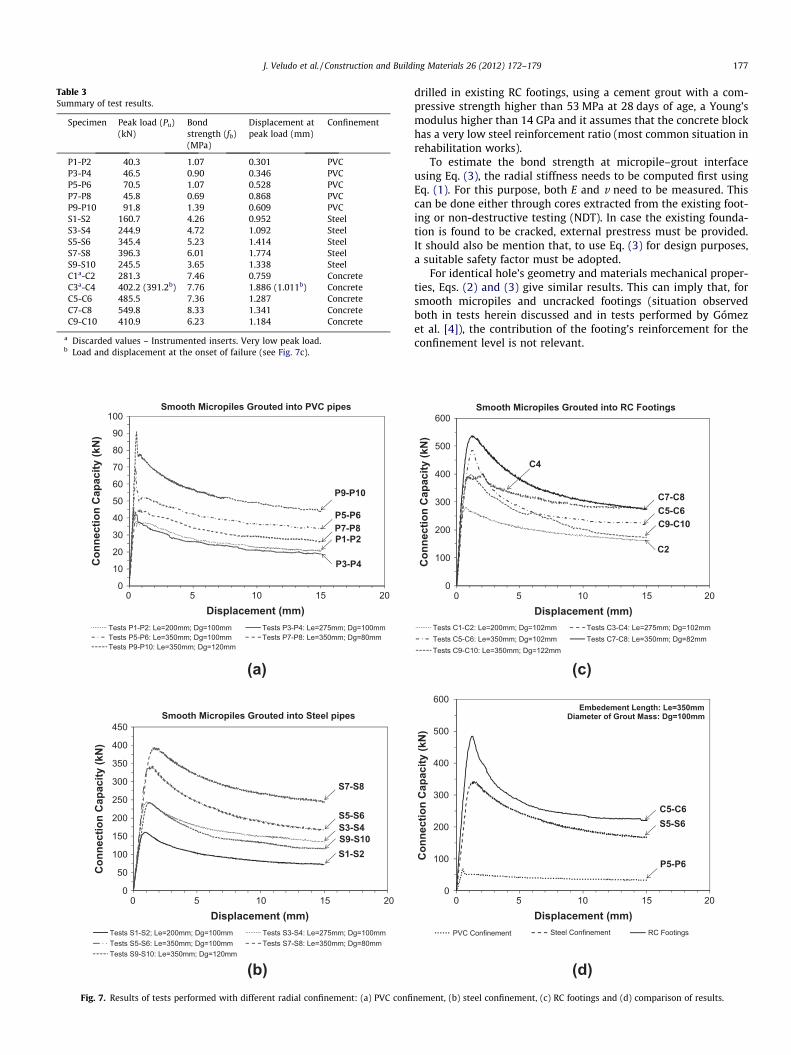
Table 3Summary of test results.
Specimen Peak load (Pu)(kN)
Bondstrength (fb)(MPa)
Displacement atpeak load (mm)
Confinement
P1-P2 40.3 1.07 0.301 PVCP3-P4 46.5 0.90 0.346 PVCP5-P6 70.5 1.07 0.528 PVCP7-P8 45.8 0.69 0.868 PVCP9-P10 91.8 1.39 0.609 PVCS1-S2 160.7 4.26 0.952 SteelS3-S4 244.9 4.72 1.092 SteelS5-S6 345.4 5.23 1.414 SteelS7-S8 396.3 6.01 1.774 SteelS9-S10 245.5 3.65 1.338 SteelC1a-C2 281.3 7.46 0.759 ConcreteC3a-C4 402.2 (391.2b) 7.76 1.886 (1.011b) ConcreteC5-C6 485.5 7.36 1.287 ConcreteC7-C8 549.8 8.33 1.341 ConcreteC9-C10 410.9 6.23 1.184 Concrete
a Discarded values – Instrumented inserts. Very low peak load.b Load and displacement at the onset of failure (see Fig. 7c).
Con
nect
ion
Cap
acity
(kN
)C
onne
ctio
n C
apac
ity (k
N)
Displacement (mm)
Smooth Micropiles Grouted into PVC pipes
Tests P1-P2: Le=200mm; Dg=100mm Tests P3-P4: Le=275mm; Dg=100mmTests P5-P6: Le=350mm; Dg=100mm Tests P7-P8: Le=350mm; Dg=80mmTests P9-P10: Le=350mm; Dg=120mm
P1-P2
P5-P6
P3-P4
P7-P8
P9-P10
Smooth Micropiles Grouted into Steel pipes
Tests S1-S2; Le=200mm; Dg=100mm Tests S3-S4: Le=275mm; Dg=100mmTests S5-S6: Le=350mm; Dg=100mm Tests S7-S8: Le=350mm; Dg=80mmTests S9-S10: Le=350mm; Dg=120mm
S1-S2S9-S10S3-S4S5-S6
S7-S8
0 5 10 15 20
Displacement (mm)0 5 10 15 20
0
10
20
30
40
50
60
70
80
90
100
0
50
100
150
200
250
300
350
400
450
(a)
(b)Fig. 7. Results of tests performed with different radial confinement: (a) PVC confi
J. Veludo et al. / Construction and Building Materials 26 (2012) 172–179 177
drilled in existing RC footings, using a cement grout with a com-pressive strength higher than 53 MPa at 28 days of age, a Young’smodulus higher than 14 GPa and it assumes that the concrete blockhas a very low steel reinforcement ratio (most common situation inrehabilitation works).
To estimate the bond strength at micropile–grout interfaceusing Eq. (3), the radial stiffness needs to be computed first usingEq. (1). For this purpose, both E and v need to be measured. Thiscan be done either through cores extracted from the existing foot-ing or non-destructive testing (NDT). In case the existing founda-tion is found to be cracked, external prestress must be provided.It should also be mention that, to use Eq. (3) for design purposes,a suitable safety factor must be adopted.
For identical hole’s geometry and materials mechanical proper-ties, Eqs. (2) and (3) give similar results. This can imply that, forsmooth micropiles and uncracked footings (situation observedboth in tests herein discussed and in tests performed by Gómezet al. [4]), the contribution of the footing’s reinforcement for theconfinement level is not relevant.
Con
nect
ion
Cap
acity
(kN
)
Displacement (mm)0 5 10 15 20
Smooth Micropiles Grouted into RC Footings
Tests C1-C2: Le=200mm; Dg=102mm Tests C3-C4: Le=275mm; Dg=102mmTests C5-C6: Le=350mm; Dg=102mm Tests C7-C8: Le=350mm; Dg=82mmTests C9-C10: Le=350mm; Dg=122mm
C4
C2
C5-C6C7-C8
C9-C10
0
100
200
300
400
500
600
(c)
(d)
Embedement Length: Le=350mmDiameter of Grout Mass: Dg=100mm
PVC Confinement Steel Confinement RC Footings
P5-P6
C5-C6S5-S6
Con
nect
ion
Cap
acity
(kN
)
Displacement (mm)0 5 10 15 20
0
100
200
300
400
500
600
nement, (b) steel confinement, (c) RC footings and (d) comparison of results.

P1-P20.30
P3-P40.35
P5-P60.53
S1-S20.95
S3-S41.10
S5-S61.41
C1-C20.76
C3-C41.01
C5-C61.29
150 200 250 300 350 400
Dis
plac
emen
t at P
eak
Load
(mm
)
Embedment Length (mm)PVC Confinement Steel Confinement RC Footings
Diameter of the Grout Mass: Dg=100mm
0.0
0.4
0.8
1.2
1.6
2.0
Fig. 8. Relationship between embedment length and the displacement at peak loadfor the same diameter of grout mass 100 mm.
fb = 0.0101Kr + 1.0214; R² = 0.9572
Bon
d St
reng
th (M
Pa)
Radial Stiffness (MPa/mm)
Embedment Length: Le=350mm
0 200 400 600 8000
1
2
3
4
5
6
7
8
9
10
Fig. 9. Relationship between bond strength and radial stiffness.
P7-P80.69
P5-P61.07
P9-P101.39
S7-S86.01
P5-P65.23
P9-P103.65
C7-C88.33
C5-C67.36
C9-C106.23
Diameter of the Grout Mass (mm)
Embedment Length: Le=350mm
PVC Confinement Steel Confinement RC Footings
70 80 90 100 110 120 130
Bon
d St
reng
th (M
Pa)
0
2
4
6
8
10
Fig. 10. Relationship between bond strength and diameter of the grout mass.
P1-P21.07
P3-P40.90
P5-P61.07
S1-S24.26
S3-S44.72
S5-S65.23
C1-C27.46
C3-C47.76 C5-C6
7.36
150 200 250 300 350 400Embedment Length (mm)
Diameter of the Grout Mass: Dg=100mm
PVC Confinement Steel Confinement RC Footings
Bon
d St
reng
th (M
Pa)
0
2
4
6
8
10
Fig. 11. Relationship between bond strength and embedment length.
178 J. Veludo et al. / Construction and Building Materials 26 (2012) 172–179
In Fig. 10, the relationship between the diameter of the groutmass and the bond strength at the micropile–grout interface isillustrated. It can be observed that, for specimens confined withPVC tubes, the bond strength increases with the diameter of thegrout mass around the insert. In this situation, the grout cover pro-vides itself confinement through tensile hoop stresses prior tocracking. On the contrary, for specimens confined with steel tubesand for specimens grouted in RC footing, it can be observed thatthe bond strength decreases with the increase of the diameter ofthe grout mass around the insert. In this situation, the bondstrength depends on the mechanical properties of the grout andon the confinement materials.
The bond strength at the micropile–grout interface versus theembedment length is presented in Fig. 11. The bond strengthseems to vary slightly with the embedment length for specimenswith steel confinement, whereas no variation is detected for spec-imens confined with PVC tubes or RC footings. These results areconsistent with those obtained by Gómez et al. [4] with smoothcasing inserts grouted in predrilled holes in RC footings.
5. Conclusions
From the experimental study herein presented, the followingconclusions can be drawn. In all tests, immediately after reaching
the peak load, a sudden decrease on the load carrying capacity ofthe specimens is observed, followed by a ductile post-failure re-sponse. In this phase, the connection capacity gradually decreasesuntil an almost constant value is reached. This residual bondstrength represents approximately 50% of the maximum bondstrength, which is still significant.
The connection capacity is first controlled by chemical adhesionat the micropile–grout interface and then by friction, being the lat-ter proportional to the radial confining. However, after the peakload, the load–displacement diagrams tend to similar rates, indi-cating that the post-peak phase is controlled by the same frictionmechanism, independently of the level of confinement.
The stiffness of the confinement materials has a major influenceon the bond strength when the Young’s modulus of the confine-ment material is smaller than that of the grout. In this case, failureoccurs by radial fracturing with radial displacement of groutwedges. On the contrary, for higher confinement levels, themechanical properties of the grout and the diameter of the groutmass are the critical parameters.
The variation of the bond strength at micropile–grout interfaceis shown to be strongly related with the confinement level (corre-lation coefficient of 0.96), therefore being this one of the mostimportant parameters.
In the case of micropiles grouted in holes predrilled in existingRC footings and for steel confinement, the bond strength increases

J. Veludo et al. / Construction and Building Materials 26 (2012) 172–179 179
with the decrease of the hole’s diameter. Consequently, increasingthe hole’s diameter is not an option to improve the connectioncapacity.
Finally, for RC footings, the bond strength does not vary signif-icantly with the embedment length.
Acknowledgement
The authors acknowledge the financial support of the compa-nies Betão-Liz; DSI; HILTI; SECIL; and SIKA.
References
[1] Armour T, Groneck P, Keeley J, Sharma S. FHWA-SA-97-070 - Micropile Designand Construction Guidelines – Implementation manual: Federal HighwayAdministration – US Department of Transportation; 2000.
[2] Cyna H, Schlosser F, Frank R, Plumelle C, Estephan R, Altamayer F, et al.FOREVER: Synthesis and recommendations of the French national project onmicropiles (1999–2003): IREX; 2004. [in French].
[3] Rasines JME. Micropiles to footing connection. In: SEMSIG-AETSS, editor.Jornadas técnicas SEMSIG-AETESS 3ª Sesión: Micropilotes Naos Livros; 2003. p.131–41. [in Spanish].
[4] Gómez J, Cadden A, Traylor RP, Bruce DA. Connection capacity betweenmicropiles and existing footings-bond strength to concrete. In: CaddenDABaAW, editor. Geo3 GEO Construction Quality Assurance/Quality ControlConference Proceedings. Dallas/Ft. Worth, TXS2005. p. 196–216.
[5] Tepfers R. Cracking of concrete cover along anchored deformed reinforcingbars. Mag Concr Res 1979;31(106):3–12.
[6] FIB. Bond of reinforcement in concrete. Lausanne, Switzerland: FédérationInternationale du Béton; 2000.
[7] ACI Committe 408. Bond development of straight reinforcing bars in tension(408R-03). Farmington Hills, Mich.: American Concrete Institute; 2003. p. 49.
[8] CEB-FIP Model Code 1990. CEB/FIP. London: Comité International du Béton(CEB); 1991.
[9] Moosavi M, Jafari A, Khosravi A. Bond of cement grouted reinforcing bars underconstant radial pressure. Cement Concr Compos 2005;27(1):103–9.
[10] Hyett AJ, Bawden WF, Macsporran GR, Moosavi M. A constitutive law for bondfailure of fully-grouted cable bolts using a modified Hoek cell. Int J Rock MechMin Sci Geomech Abstracts 1995;32(1):11–36.
[11] Hyett AJ, Bawden WF, Reichert RD. The effect of rock mass confinement on thebond strength of fully grouted cable bolts. Int J Rock Mech Min Sci Geomech1992;29(5):503–24.
[12] Yahia A, Khayat K, Benmokrane B. Bond strength of cement grout anchors castin dry and submerged conditions. Ground anchorages and anchoredstructures. London, UK: Thomas Telford; 1997. p. 89–99.
[13] Malvar LJ. Bond reinforcement under controlled confinement. ACI Mater J1992;89(6):593–601.
[14] Noghabai K. Effect of tension softening on the performance of concretestructures. Experimental, analytical and computational studies. LuleåUniversity of Technology; 1998.
[15] ACI Committee 318. Building code requirements for structural concrete andcommentary (ACI 318M-05). Farmington Hills, Mich.: American ConcreteInstitute; 2005. p. 438.
[16] CEN. Eurocode 2: Design of concrete structures – Part 1-1: General rules andrules for buildings (EN 1992-1-1). Brussels: European Committee forStandardization; 2004. p. 225.
[17] Santos PMD, Júlio ENBS. Development of a laser roughness analyser to predictin situ the bond strength of concrete-to-concrete interfaces. Mag Concr Res2008;60(5):329–37.
[18] CEN. EN 196-1 Methods of testing cement – Part 1: Determination of strength.European Committee for Standardization; 2005.
[19] EN 445: Grout for prestressing tendons. Test methods. European Committeefor Standarditazion; 2000. p. 19.
[20] LNEC. Especificação E 397 – Static Modulus of Elasticity of Concrete UnderCompression. Laboratório Nacional de Engenharia Civil; 1993. p. 2. (inPortuguese).
[21] EN 447: Grout for prestressing tendons. Basic requirements. EuropeanCommittee for Standarditazion; 2000. p. 14.
[22] CEN. EN 12390-1 Testing hardened concrete – Part 1: Shape, dimensions andother requirements for specimens and moulds. European Committee forStandardization; 2000.
[23] CEN. EN 12390-3 Testing hardened concrete – Part 3: Compressive strength oftest specimens. European Committee for Standardization (CEN); 2003.
[24] Timoshenko SP, Goodier JN. Theory of Elasticity. 3rd ed., Rio de Janeiro: EditoraGuanabara Dois; 1980. (in Portuguese).