compressed air filters atlas copco - total tools
TRANSCRIPT

Atlas CopcoCompressed air filters
DD 10+-550+ - DDh 15+-490+, DDp 10+-550+ - DDhp 15+-490+,PD 10+-550+ - PDh 15+-490+, PDp 10+-550+ - PDhp 15+-490+,QD 10+-550+ - QDh 15+-490+, UD 9+-550+
Instruction book

Atlas CopcoCompressed air filters
DD 10+-550+ - DDh 15+-490+,DDp 10+-550+ - DDhp 15+-490+,PD 10+-550+ - PDh 15+-490+,PDp 10+-550+ - PDhp 15+-490+,QD 10+-550+ - QDh 15+-490+, UD 9+-550+
Instruction bookOriginal instructions
Copyright noticeAny unauthorized use or copying of the contents or any part thereof is prohibited.
This applies in particular to trademarks, model denominations, part numbers anddrawings.
This instruction book is valid for CE as well as non-CE labelled machines. It meets therequirements for instructions specified by the applicable European directives asidentified in the Declaration of Conformity.
2015 - 02
No. 2920 7150 00
www.atlascopco.com
Table of contents
1 Safety precautions..........................................................................................................4
1.1 SAFETY ICONS................................................................................................................................... 4
1.2 SAFETY PRECAUTIONS DURING INSTALLATION...........................................................................................4
1.3 SAFETY PRECAUTIONS DURING OPERATION.............................................................................................. 5
1.4 SAFETY PRECAUTIONS DURING MAINTENANCE OR REPAIR........................................................................... 5
2 Description......................................................................................................................7
2.1 DESCRIPTION OF FILTERS.....................................................................................................................7
2.2 OPTIONS.......................................................................................................................................... 9
3 Installation.....................................................................................................................13
3.1 GENERAL REMARKS.......................................................................................................................... 13
3.2 SPECIFIC REMARKS...........................................................................................................................14
3.3 ISO 8573-1:2010......................................................................................................................... 14
3.4 ISO 12500................................................................................................................................... 19
4 Maintenance..................................................................................................................20
4.1 MAINTENANCE................................................................................................................................. 20
4.2 FILTER ELEMENT CHANGE...................................................................................................................20
4.3 SERVICE INTERVALS..........................................................................................................................21
4.4 FILTER DISPOSAL..............................................................................................................................22
5 Technical data 16 bar filters........................................................................................ 23
5.1 REFERENCE CONDITIONS................................................................................................................... 23
5.2 PRINCIPAL DATA...............................................................................................................................23
5.3 SPECIFIC DATA................................................................................................................................ 23
5.4 RATED FLOW AT REFERENCE CONDITIONS............................................................................................. 25
5.5 CORRECTION FACTORS......................................................................................................................25
Instruction book
2 2920 7150 00

5.6 DIMENSIONS AND WEIGHT.................................................................................................................. 25
5.7 SUPPLIED COMPONENTS.................................................................................................................... 27
6 Technical data 20 bar filters........................................................................................ 29
6.1 REFERENCE CONDITIONS................................................................................................................... 29
6.2 PRINCIPAL DATA...............................................................................................................................29
6.3 SPECIFIC DATA................................................................................................................................ 29
6.4 RATED FLOW AT REFERENCE CONDITIONS............................................................................................. 30
6.5 CORRECTION FACTORS......................................................................................................................30
6.6 DIMENSIONS AND WEIGHT.................................................................................................................. 31
6.7 SUPPLIED COMPONENTS.................................................................................................................... 32
Instruction book
2920 7150 00 3

1 Safety precautions
1.1 Safety icons
Explanation
Danger for life
Warning
Important note
1.2 Safety precautions during installation1. Place the device where the ambient air is cool and as clean as possible. Consult section Reference
conditions and limitations.2. During installation or any other intervention on one of the connected machines, the machines must be
stopped, de-energized and the isolating switch opened and locked before any maintenance or repair.As a further safeguard, persons switching on remotely controlled machines shall take adequateprecautions to ensure that there is no one checking or working on the machine. To this end, a suitablenotice shall be affixed to the start equipment.
3. Install the equipment in an area free of flammable fumes, vapours and particles, e.g. paint solvents,that can lead to internal fire or explosion.
4. The electrical connections must correspond to the applicable codes. The device must be earthed andprotected against short circuits by fuses in all phases. A lockable power isolating switch must beinstalled near the device.
5. For machines controlled by a central control system, a sign stating "This machine may start withoutwarning" must be affixed near the instrument panel.
6. In multiple compressor systems, manual valves must be installed to isolate each compressor. Non-return valves (check valves) must not be relied upon for isolating pressure systems.
7. Never remove or tamper with the safety devices.
Also consult following safety precautions: Safety precautions during operation andSafety precautions during maintenance or repair.These precautions apply to electrical devices.For precautions applying to the connected equipment consult the relevant instructionbook.Some precautions are general and cover several machine types and equipment; hencesome statements may not apply to your device.
Instruction book
4 2920 7150 00

1.3 Safety precautions during operationAll responsibility for any damage or injury resulting from neglecting these precautions, ornon-observance of the normal caution and care required for installation, operation,maintenance and repair, even if not expressly stated, will be disclaimed by themanufacturer.
1. Persons switching on remotely controlled machines shall take adequate precautions to ensure thatthere is no one checking or working on the machine. To this end, a suitable notice shall be affixed tothe remote start equipment.
2. Never operate the device in the presence of flammable or toxic fumes, vapours or particles.3. Never operate the device below or in excess of its limit ratings.4. Do not operate the device when there are flammable or toxic fumes, vapors or particles.5. Keep all bodywork doors and panels closed during operation. The doors may be opened for short
periods only, e.g. to carry out routine checks.6. People staying in environments or rooms where the sound pressure level reaches or exceeds 90 dB(A)
shall wear ear protectors.7. Periodically check that:
• All guards and fasteners are in place and tight• All hoses and/or pipes are in good condition, secure and not rubbing• There are no leaks• All electrical leads are secure and in good order
8. Never remove or tamper with the safety devices.
Also consult following safety precautions: Safety precautions during installation andSafety precautions during maintenance or repair.These precautions apply to electrical devices.For precautions applying to the connected equipment consult the relevant instructionbook.Some precautions are general and cover several machine types and equipment; hencesome statements may not apply to your machine.
1.4 Safety precautions during maintenance or repairAll responsibility for any damage or injury resulting from neglecting these precautions, ornon observance of the normal caution and care required for installation, operation,maintenance and repair, even if not expressly stated, will be disclaimed by themanufacturer.
1. Use only the correct tools for maintenance and repair work.2. Use only genuine spare parts.3. A warning sign bearing a legend such as "Work in progress - do not start" shall be attached to the
starting equipment, including all remote start equipment.4. Persons switching on remotely controlled machines shall take adequate precautions to ensure that
there is no one checking or working on the machine. To this end, a suitable notice shall be affixed tothe remote start equipment.
5. Never use flammable solvents or carbon tetrachloride for cleaning parts. Take safety precautionsagainst toxic vapours of cleaning liquids.
6. Scrupulously observe cleanliness during maintenance and repair. Keep dirt away by covering theparts and exposed openings with a clean cloth, paper or tape.
Instruction book
2920 7150 00 5
7. Never use a light source with open flame for inspecting the interior of the device.8. All regulating and safety devices shall be maintained with due care to ensure that they function
properly. They may not be put out of action.9. Before clearing the device for use after maintenance or repair, check that operating pressures,
temperatures and time settings are correct. Check that all control and shut-down devices are fitted andthat they function correctly.
10. Make sure that no tools, loose parts or rags are left in or on the device.11. Never use caustic solvents which can damage materials of the device.
Also consult following safety precautions: Safety precautions during installation andSafety precautions during operation.These precautions apply to electrical devices.For precautions applying to the connected equipment consult the relevant instructionbook.Some precautions are general and cover several machine types and equipment; hencesome statements may not apply to your machine.
Units and/or used parts should be disposed of in an environmentally friendly and safemanner and in line with the local recommendations and legislation.
Instruction book
6 2920 7150 00
2 Description
2.1 Description of filters
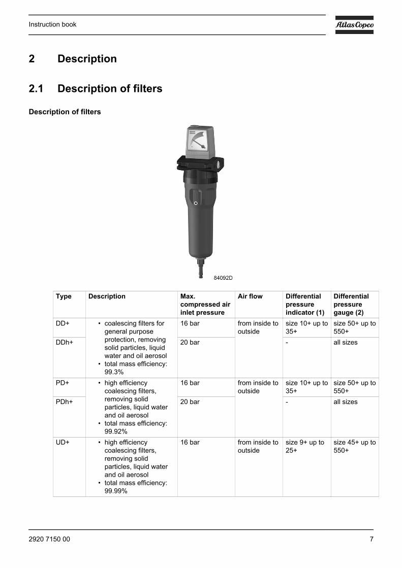
Description of filters
Type Description Max.compressed airinlet pressure
Air flow Differentialpressureindicator (1)
Differentialpressuregauge (2)
DD+ • coalescing filters forgeneral purposeprotection, removingsolid particles, liquidwater and oil aerosol
• total mass efficiency:99.3%
16 bar from inside tooutside
size 10+ up to35+
size 50+ up to550+
DDh+ 20 bar - all sizes
PD+ • high efficiencycoalescing filters,removing solidparticles, liquid waterand oil aerosol
• total mass efficiency:99.92%
16 bar from inside tooutside
size 10+ up to35+
size 50+ up to550+
PDh+ 20 bar - all sizes
UD+ • high efficiencycoalescing filters,removing solidparticles, liquid waterand oil aerosol
• total mass efficiency:99.99%
16 bar from inside tooutside
size 9+ up to25+
size 45+ up to550+
Instruction book
2920 7150 00 7
Type Description Max.compressed airinlet pressure
Air flow Differentialpressureindicator (1)
Differentialpressuregauge (2)
DDp+ • particulate filters fordust protection
• count efficiency:99.92% at mostpenetrating particle size
16 bar from outsideto inside
size 10+ up to35+
size 50+ up to550+
DDhp+ 20 bar - all sizes
PDp+ • high-efficiencyparticulate filters fordust protection
• count efficiency:99.98% at mostpenetrating particle size
16 bar size 10+ up to35+
size 50+ up to550+
PDhp+ 20 bar - all sizes
QD+ • oil vapour and odourremoval filter
• air flows through theactivated carbon whichis contained in the QDfilter element and whichabsorbs oil vapoursand odours
16 bar from inside tooutside orfrom outsideto inside
- -QDh+ 20 bar - -
The QD+/QDh+ filter does not remove methane, carbon monoxide, carbon dioxide or othertoxic gases and fumes!
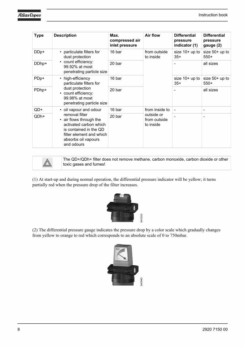
(1) At start-up and during normal operation, the differential pressure indicator will be yellow; it turnspartially red when the pressure drop of the filter increases.
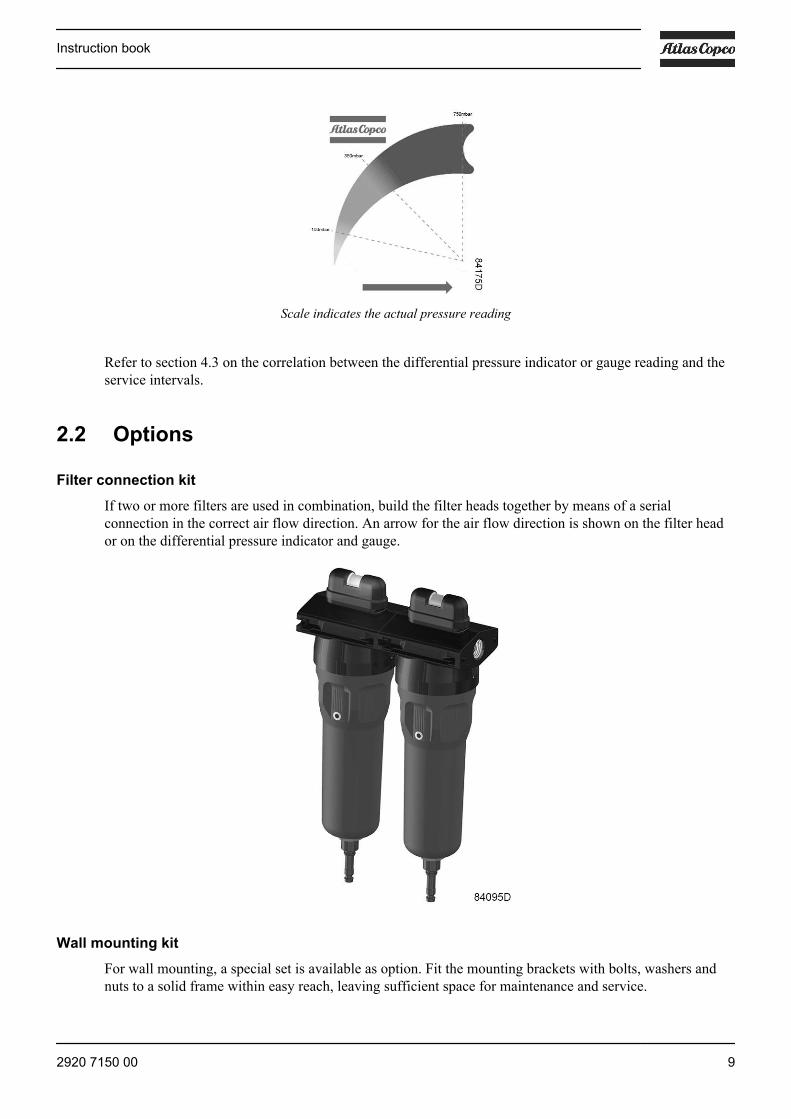
(2) The differential pressure gauge indicates the pressure drop by a color scale which gradually changesfrom yellow to orange to red which corresponds to an absolute scale of 0 to 750mbar.
Instruction book
8 2920 7150 00
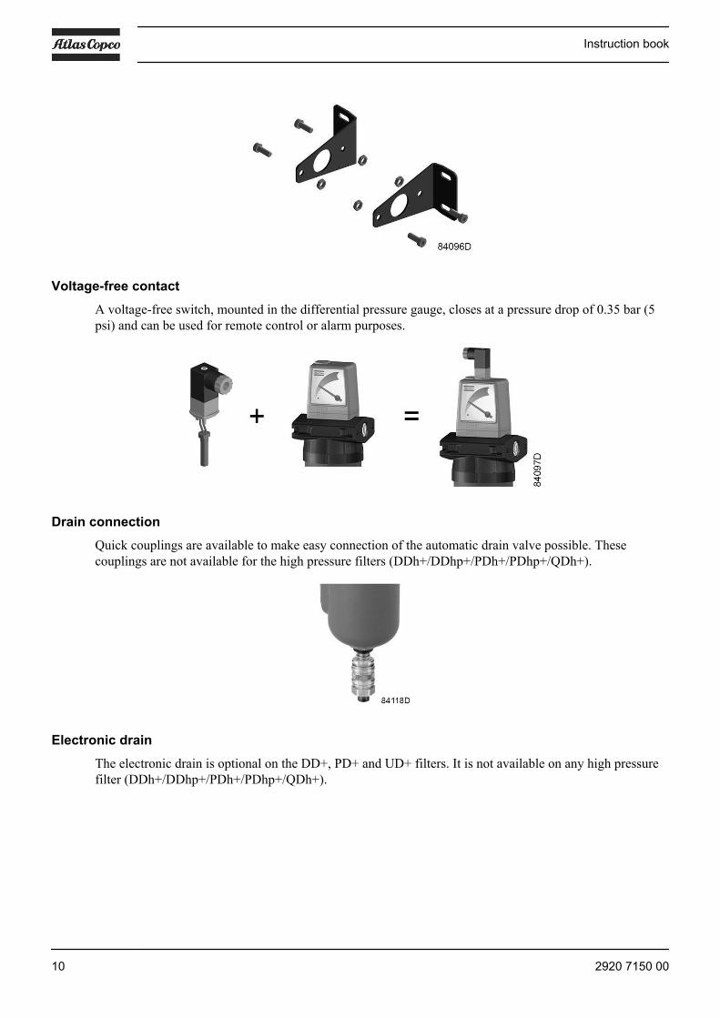
Scale indicates the actual pressure reading
Refer to section 4.3 on the correlation between the differential pressure indicator or gauge reading and theservice intervals.
2.2 Options
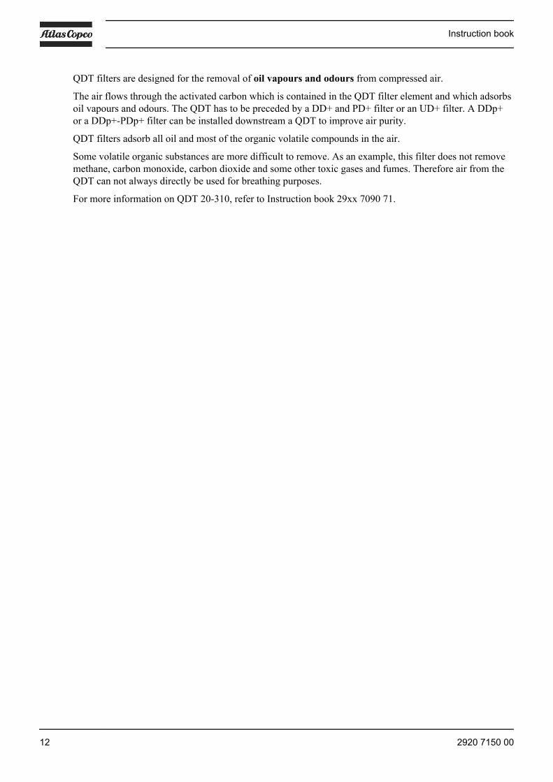
Filter connection kitIf two or more filters are used in combination, build the filter heads together by means of a serialconnection in the correct air flow direction. An arrow for the air flow direction is shown on the filter heador on the differential pressure indicator and gauge.
Wall mounting kitFor wall mounting, a special set is available as option. Fit the mounting brackets with bolts, washers andnuts to a solid frame within easy reach, leaving sufficient space for maintenance and service.
Instruction book
2920 7150 00 9
Voltage-free contactA voltage-free switch, mounted in the differential pressure gauge, closes at a pressure drop of 0.35 bar (5psi) and can be used for remote control or alarm purposes.
Drain connectionQuick couplings are available to make easy connection of the automatic drain valve possible. Thesecouplings are not available for the high pressure filters (DDh+/DDhp+/PDh+/PDhp+/QDh+).
Electronic drainThe electronic drain is optional on the DD+, PD+ and UD+ filters. It is not available on any high pressurefilter (DDh+/DDhp+/PDh+/PDhp+/QDh+).
Instruction book
10 2920 7150 00

The electronic drain is a zero loss, electronically operated drain valve, specially designed to drain oilcondensate. A sensor senses the condensate level. If this level exceeds a preset value, the drain waits for afixed programmed time, then a solenoid valve is activated and the condensate is discharged. When all thecondensate is discharged, the solenoid valve closes and condensate is collected again. This way, the loss ofair is reduced to a minimum.
If the microcontroller registers a malfunction, the automatic drain valve will automatically change to alarmmode. This alarm signal can be relayed via a potential-free contact.
The electronic drain is available for 3 operating voltages: 220 V, 115 V and 24 V. An extra electric wiringcan be foreseen to connect the potential free contacts and an external test button.
Always remove the manual drain or the automatic drain of the filter before installing theelectronic drain.
Activated Carbon Tower QDT
Instruction book
2920 7150 00 11
QDT filters are designed for the removal of oil vapours and odours from compressed air.
The air flows through the activated carbon which is contained in the QDT filter element and which adsorbsoil vapours and odours. The QDT has to be preceded by a DD+ and PD+ filter or an UD+ filter. A DDp+or a DDp+-PDp+ filter can be installed downstream a QDT to improve air purity.
QDT filters adsorb all oil and most of the organic volatile compounds in the air.
Some volatile organic substances are more difficult to remove. As an example, this filter does not removemethane, carbon monoxide, carbon dioxide and some other toxic gases and fumes. Therefore air from theQDT can not always directly be used for breathing purposes.
For more information on QDT 20-310, refer to Instruction book 29xx 7090 71.
Instruction book
12 2920 7150 00
3 Installation
3.1 General remarks
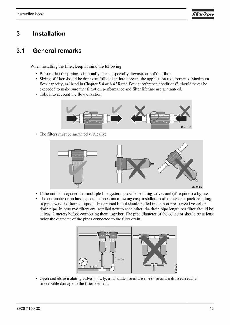
When installing the filter, keep in mind the following:
• Be sure that the piping is internally clean, especially downstream of the filter.• Sizing of filter should be done carefully taken into account the application requirements. Maximum
flow capacity, as listed in Chapter 5.4 or 6.4 "Rated flow at reference conditions", should never beexceeded to make sure that filtration performance and filter lifetime are guaranteed.
• Take into account the flow direction:
• The filters must be mounted vertically:
• If the unit is integrated in a multiple line system, provide isolating valves and (if required) a bypass.• The automatic drain has a special connection allowing easy installation of a hose or a quick coupling
to pipe away the drained liquid. This drained liquid should be fed into a non-pressurized vessel ordrain pipe. In case two filters are installed next to each other, the drain pipe length per filter should beat least 2 meters before connecting them together. The pipe diameter of the collector should be at leasttwice the diameter of the pipes connected to the filter drain.
• Open and close isolating valves slowly, as a sudden pressure rise or pressure drop can causeirreversible damage to the filter element.
Instruction book
2920 7150 00 13

3.2 Specific remarks
DD+/DDh+ filterThe filter should be preceded by a water separator if no water separator is integrated in the after cooler ofthe compressor. In case a dryer is preceding the filter, a water separator is no longer required.
PD+/PDh+ filterIt is recommended to install a DD+/DDh+ filter upstream the PD+/PDh+ filter. If not, the load on the PD+/PDh+ filter element may become too high and will reduce its lifetime.
DDp+/DDhp+ and PDp+/PDhp+ filterWhen the DDp+/DDhp+ and PDp+/PDhp+ filters are used with an adsorption type air dryer, install thefilter downstream of the dryer.
UD+ filterThe filter should be preceded by a water separator if no water separator is integrated in the after cooler ofthe compressor. In case a dryer is preceding the filter, a water separator is no longer required.
QD+/QDh+ filterTo protect the active carbon element, a QD+/QDh+ filter must always be preceded by a DD+/DDh+ filterand a PD+/PDh+ filter.
The filter should be mounted as close as possible to the point of use of the air.
3.3 ISO 8573-1:2010
GeneralFor new installations as well as for installations that have to be made up-to-date, the ISO 8573-1:2010standard can be used. Some proposals are given fulfilling this standard.
This part specifies purity classes of compressed air with respect to particles, water and oil, independent ofthe location in the compressed air system at which the air is specified or measured, for ISO 8573-1:2010standard.
Instruction book
14 2920 7150 00
The ISO 8573-1:2010 standard only concerns compressed air for general use and doesnot deal with, or is not applicable to, e.g. breathing air.
ISOclass
Dust Water Oil
Maximum number of particles per m3 asfunction of particle size d
Pressure dew point Total oil concentration(aerosol, liquid andvapour) mg/m3
0.1< d ≤0.5μm
0.5< d ≤1.0μm
1.0< d ≤5.0μm
°C °F
0 As specified by the equipment user or supplier and more stringent than class 11 ≤ 20000 ≤ 400 ≤ 10 ≤ -70 ≤ -94 ≤0.012 ≤ 400000 ≤ 6000 ≤ 100 ≤ -40 ≤ -40 ≤0.13 not specified ≤ 90000 ≤ 1000 ≤ -20 ≤ -4 ≤14 not specified not specified ≤ 10000 ≤ +3 ≤ +37.4 ≤55 not specified not specified ≤ 100000 ≤ +7 ≤ +44.6 -6 mass concentration: 1 - 5 mg/m3 ≤ +10 ≤ +50 -
Terms and definitionsParticle: small discrete mass of solid or liquid matter
Particle size d : length of the greatest distance between two external boundaries
Dew point: temperature at which water vapour begins to condense
Pressure dew point: dew point of the air at the specified pressure
A desiccant dryer will be needed to reduce the dew point down to -40 °C (-40°F).
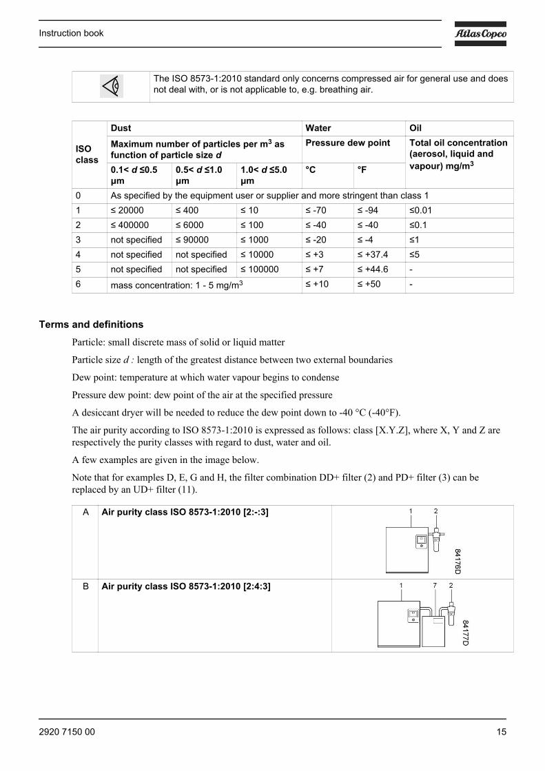
The air purity according to ISO 8573-1:2010 is expressed as follows: class [X.Y.Z], where X, Y and Z arerespectively the purity classes with regard to dust, water and oil.
A few examples are given in the image below.
Note that for examples D, E, G and H, the filter combination DD+ filter (2) and PD+ filter (3) can bereplaced by an UD+ filter (11).
A Air purity class ISO 8573-1:2010 [2:-:3]
B Air purity class ISO 8573-1:2010 [2:4:3]
Instruction book
2920 7150 00 15
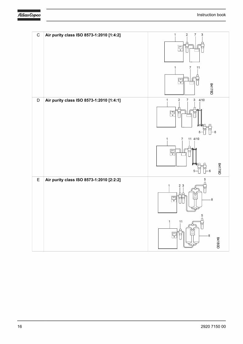
C Air purity class ISO 8573-1:2010 [1:4:2]
D Air purity class ISO 8573-1:2010 [1:4:1]
E Air purity class ISO 8573-1:2010 [2:2:2]
Instruction book
16 2920 7150 00

F Air purity class ISO 8573-1:2010 [1:2:2]
G Air purity class ISO 8573-1:2010 [2:2:1]
H Air purity class ISO 8573-1:2010 [1:2:1]
I Air purity class ISO 8573-1:2010 [2:-:0]
Instruction book
2920 7150 00 17

J Air purity class ISO 8573-1:2010 [1:-:0]
K Air purity class ISO 8573-1:2010 [2:4:0]
L Air purity class ISO 8573-1:2010 [2:2:0]
M Air purity class ISO 8573-1:2010 [1:2:0]
Components shown in above image
Item Description Item Description1 Oil-injected compressor
Compressor should be equipped with a freewater separation system (for example aftercooler incl. drain or a water separator(WSD)). No free water should enter thefiltration system.
7 FD refrigerant dryer
2 DD+/DDh+ filter 8 CD desiccant dryer3 PD+/PDh+ filter 9 Oil-free compressor
Compressor should be equipped with a freewater separation system (for example aftercooler incl. drain or a water separator (WSD)).No free water should enter the filtration system.
Instruction book
18 2920 7150 00

Item Description Item Description4 QD+/QDh+ filter 10 QDT filter (for critical applications)5 DDp+/DDhp+ filter 11 UD+ filter6 PDp+/PDhp+ filter - -
Compressed air may come into direct or indirect contact with food. When this happens, for example duringproduction or processing, this requires a much higher level of contaminant control. Particular attentionneeds to be given to contaminants added during the compression and the distribution process, such as breadpackaging, fluidized bed in the transfer of flour from a tanker etc.
Recommendations:• No contact: Air purity class ISO 8573-1:2010 [1:4:1]• Contact: Air purity class ISO 8573-1:2010 [1:2:1]
The filters comply with the bacteriological filtration grade and the British Compressed Air Society (BCAS)Food Grade Compressed Air Code of Practice.
3.4 ISO 12500
ISO 12500ISO 12500 has been introduced specifically to test purification equipment for compressed air andcomplements ISO 8573.
ISO 12500 currently consists of:
• Part 1: Oil aerosol filters• Part 2: Oil vapor filters• Part 3: Particulate filters• Part 4: Water removal
ISO 12500-1:2007 - Testing of Coalescing filters
ISO 12500-1:2007 provides a set of standardized conditions with which coalescing filters should be testedin order to show their filtration performance in accordance with ISO 8573-1:2010. The testing will providethe user with an oil aerosol carry-over figure in mg/m3 and saturated (or wet) pressure drop in mbar. This isthe filter performance at the reference conditions and can be used for benchmarking purposes.
ISO 12500-3:2009 - Testing of Dust removal filters
ISO 12500-3:2009 provides a guide for choosing an appropriate method of determining the solidparticulate removal efficiency rating by particle size. Measurement methods are recommended based on thesize range of the particulates that the filter being tested has been designed to remove. The test is performedas a type-test on filters as being representative of a range.
Instruction book
2920 7150 00 19

4 Maintenance
4.1 Maintenance
When maintaining the filter, keep in mind the following:• On filters with manual drain valve, open the latter at regular intervals to evacuate collected dust or
liquid.• In case an automatic drain valve or a solenoid timer drain is installed, manual draining can be carried
out by turning the connection nipple of the automatic drain valve counterclockwise.
When the filter has to process air with a temperature higher than the specified maximumtemperature, the filter's lifetime will be reduced considerably!
4.2 Filter element changeThe hand-tool icon on the figure indicates the items provided in a dedicated filter kit.
1. Before filter element change, check for any leakages at the bottom of the filter bowl (connection ofmanual and automatic drain) during normal filter operation. If no leakage is observed, point 6 up to 9can be discarded.
2. Isolate the filter from the air net.3. Depressurize the filter by turning the connection nipple of the automatic drain valve counterclockwise
or by opening the manual drain valve.4. Unscrew the bowl. A whistling noise will warn you if the bowl is not fully depressurized. If this
occurs, the bowl should be screwed back and the venting should be repeated.5. Discard the filter element.
Instruction book
20 2920 7150 00
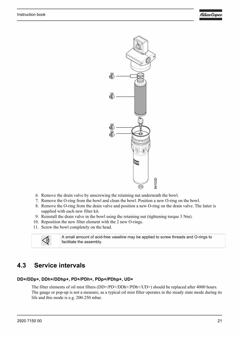
6. Remove the drain valve by unscrewing the retaining nut underneath the bowl.7. Remove the O-ring from the bowl and clean the bowl. Position a new O-ring on the bowl.8. Remove the O-ring from the drain valve and position a new O-ring on the drain valve. The latter is
supplied with each new filter kit.9. Reinstall the drain valve in the bowl using the retaining nut (tightening torque 3 Nm).
10. Reposition the new filter element with the 2 new O-rings.11. Screw the bowl completely on the head.
A small amount of acid-free vaseline may be applied to screw threads and O-rings tofacilitate the assembly.
4.3 Service intervals
DD+/DDp+, DDh+/DDhp+, PD+/PDh+, PDp+/PDhp+, UD+The filter elements of oil mist filters (DD+/PD+/DDh+/PDh+/UD+) should be replaced after 4000 hours.The gauge or pop-up is not a measure, as a typical oil mist filter operates in the steady state mode during itslife and this mode is e.g. 200-250 mbar.
Instruction book
2920 7150 00 21
Note that the indicator or gauge will not move into the red area but will stay yellow or orange duringoperation.
The filter elements of dust filters (DDp+/PDp+/DDhp+/PDhp+) should be replaced after 4000 hours orwhen the pressure drop reaches 350 mbar (whatever comes first).
The pressure drop is reached when the indicator or gauge turns red.
Summarizing, the following service intervals should be observed (whatever comes first):
• 4000 operating hours• 12 months in use• Pressure drop: 350 mbar
QD+/QDh+For QD+/QDh+ filters, the change interval of the adsorption element is approximately 1000 operatinghours or yearly. Its pressure drop will not increase during its useful life. Nevertheless, the adsorptionelement must be changed earlier at the first signs of oil vapor and odor.
4.4 Filter disposal
Used filters must be disposed of in an environmentally friendly and safe manner, and in line with the localrecommendations and environmental legislation.
Instruction book
22 2920 7150 00
5 Technical data 16 bar filters
5.1 Reference conditions
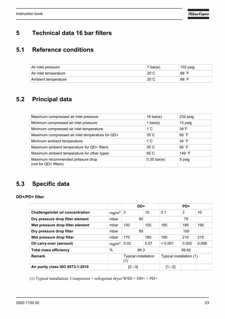
Air inlet pressure 7 bar(e) 102 psigAir inlet temperature 20˚C 68 ˚FAmbient temperature 20˚C 68 ˚F
5.2 Principal data
Maximum compressed air inlet pressure 16 bar(e) 232 psigMinimum compressed air inlet pressure 1 bar(e) 15 psigMinimum compressed air inlet temperature 1˚C 34˚FMaximum compressed air inlet temperature for QD+ 35˚C 95 ˚FMinimum ambient temperature 1˚C 34 ˚FMaximum ambient temperature for QD+ filters. 35˚C 95 ˚FMaximum ambient temperature for other types 65˚C 149 ˚FMaximum recommended pressure drop(not for QD+ filters)
0.35 bar(e) 5 psig
5.3 Specific data
DD+/PD+ filter
DD+ PD+Challenge/inlet oil concentration mg/m3 3 10 0.1 3 10
Dry pressure drop filter element mbar 60 75Wet pressure drop filter element mbar 150 155 165 185 190Dry pressure drop filter mbar 85 100Wet pressure drop filter mbar 170 180 190 210 215Oil carry-over (aerosol) mg/m3 0.02 0.07 < 0.001 0.002 0.008
Total mass efficiency % 99.3 99.92Remark Typical installation
(1)Typical installation (1)
Air purity class ISO 8573-1:2010 [2:-:3] [1:-:2]
(1) Typical installation: Compressor + refrigerant dryer/WSD + DD+ + PD+
Instruction book
2920 7150 00 23
UD+ filter
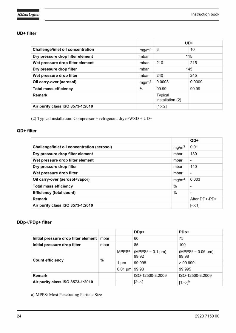
UD+Challenge/inlet oil concentration mg/m3 3 10
Dry pressure drop filter element mbar 115Wet pressure drop filter element mbar 210 215Dry pressure drop filter mbar 145Wet pressure drop filter mbar 240 245Oil carry-over (aerosol) mg/m3 0.0003 0.0009
Total mass efficiency % 99.99 99.99Remark Typical
installation (2)
Air purity class ISO 8573-1:2010 [1:-:2]
(2) Typical installation: Compressor + refrigerant dryer/WSD + UD+
QD+ filter
QD+Challenge/inlet oil concentration (aerosol) mg/m3 0.01
Dry pressure drop filter element mbar 130Wet pressure drop filter element mbar -Dry pressure drop filter mbar 140Wet pressure drop filter mbar -Oil carry-over (aerosol+vapor) mg/m3 0.003
Total mass efficiency % -Efficiency (total count) % -Remark After DD+-PD+Air purity class ISO 8573-1:2010 [-:-:1]
DDp+/PDp+ filter
DDp+ PDp+Initial pressure drop filter element mbar 60 75Initial pressure drop filter mbar 85 100
Count efficiency %
MPPSa (MPPSa = 0.1 µm)99.92
(MPPSa = 0.06 µm)99.98
1 µm 99.998 > 99.9990.01 µm 99.93 99.995
Remark ISO-12500-3:2009 ISO-12500-3:2009Air purity class ISO 8573-1:2010 [2:-:-] [1:-:-]b
a) MPPS: Most Penetrating Particle Size
Instruction book
24 2920 7150 00
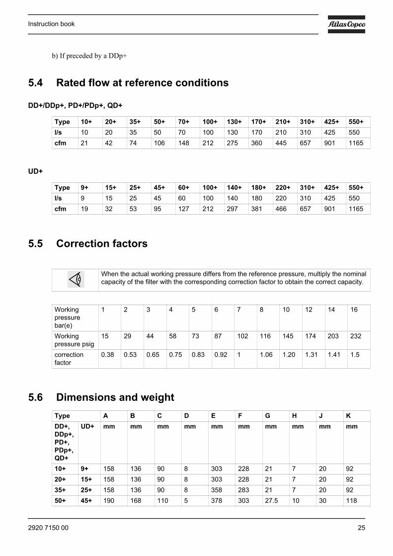
b) If preceded by a DDp+
5.4 Rated flow at reference conditions
DD+/DDp+, PD+/PDp+, QD+
Type 10+ 20+ 35+ 50+ 70+ 100+ 130+ 170+ 210+ 310+ 425+ 550+l/s 10 20 35 50 70 100 130 170 210 310 425 550cfm 21 42 74 106 148 212 275 360 445 657 901 1165
UD+
Type 9+ 15+ 25+ 45+ 60+ 100+ 140+ 180+ 220+ 310+ 425+ 550+l/s 9 15 25 45 60 100 140 180 220 310 425 550cfm 19 32 53 95 127 212 297 381 466 657 901 1165
5.5 Correction factors
When the actual working pressure differs from the reference pressure, multiply the nominalcapacity of the filter with the corresponding correction factor to obtain the correct capacity.
Workingpressurebar(e)
1 2 3 4 5 6 7 8 10 12 14 16
Workingpressure psig
15 29 44 58 73 87 102 116 145 174 203 232
correctionfactor
0.38 0.53 0.65 0.75 0.83 0.92 1 1.06 1.20 1.31 1.41 1.5
5.6 Dimensions and weightType A B C D E F G H J KDD+,DDp+,PD+,PDp+,QD+
UD+ mm mm mm mm mm mm mm mm mm mm
10+ 9+ 158 136 90 8 303 228 21 7 20 9220+ 15+ 158 136 90 8 303 228 21 7 20 9235+ 25+ 158 136 90 8 358 283 21 7 20 9250+ 45+ 190 168 110 5 378 303 27.5 10 30 118
Instruction book
2920 7150 00 25
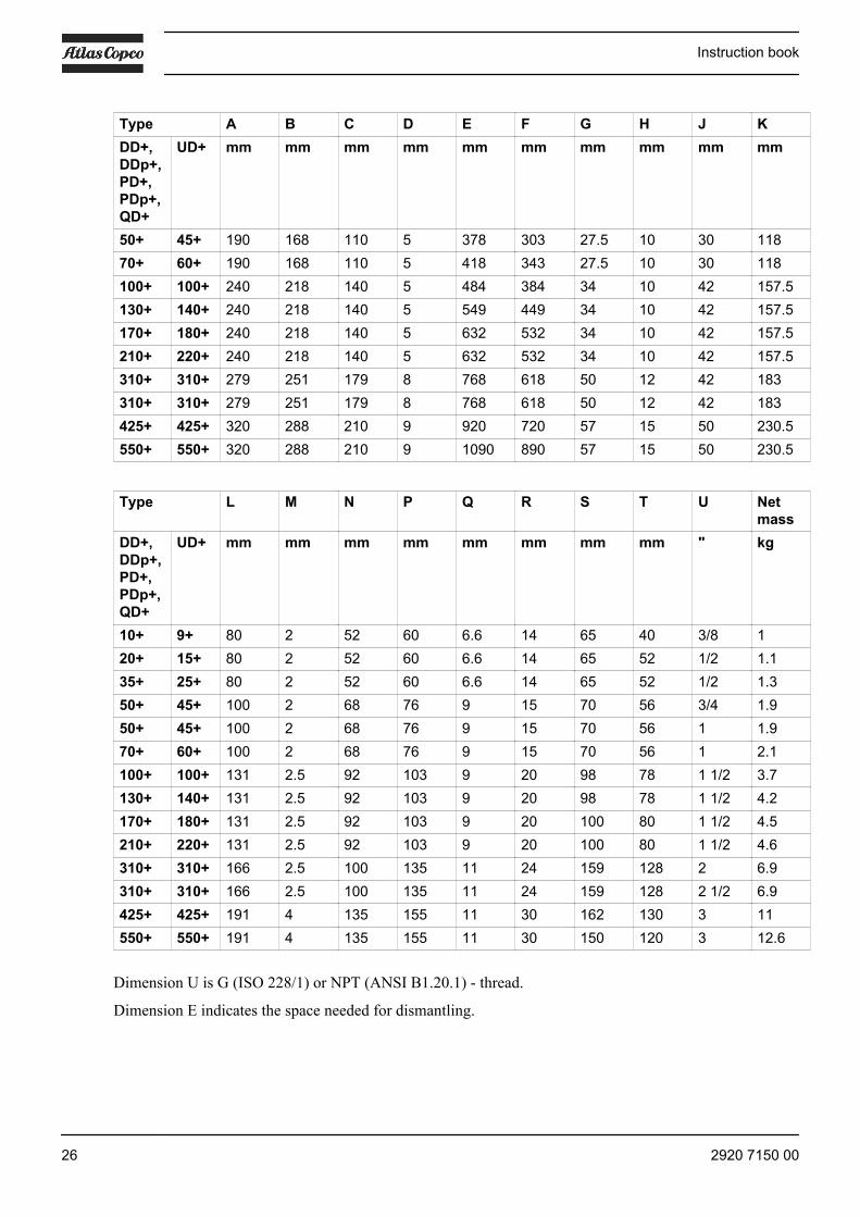
Type A B C D E F G H J KDD+,DDp+,PD+,PDp+,QD+
UD+ mm mm mm mm mm mm mm mm mm mm
50+ 45+ 190 168 110 5 378 303 27.5 10 30 11870+ 60+ 190 168 110 5 418 343 27.5 10 30 118100+ 100+ 240 218 140 5 484 384 34 10 42 157.5130+ 140+ 240 218 140 5 549 449 34 10 42 157.5170+ 180+ 240 218 140 5 632 532 34 10 42 157.5210+ 220+ 240 218 140 5 632 532 34 10 42 157.5310+ 310+ 279 251 179 8 768 618 50 12 42 183310+ 310+ 279 251 179 8 768 618 50 12 42 183425+ 425+ 320 288 210 9 920 720 57 15 50 230.5550+ 550+ 320 288 210 9 1090 890 57 15 50 230.5
Type L M N P Q R S T U Netmass
DD+,DDp+,PD+,PDp+,QD+
UD+ mm mm mm mm mm mm mm mm " kg
10+ 9+ 80 2 52 60 6.6 14 65 40 3/8 120+ 15+ 80 2 52 60 6.6 14 65 52 1/2 1.135+ 25+ 80 2 52 60 6.6 14 65 52 1/2 1.350+ 45+ 100 2 68 76 9 15 70 56 3/4 1.950+ 45+ 100 2 68 76 9 15 70 56 1 1.970+ 60+ 100 2 68 76 9 15 70 56 1 2.1100+ 100+ 131 2.5 92 103 9 20 98 78 1 1/2 3.7130+ 140+ 131 2.5 92 103 9 20 98 78 1 1/2 4.2170+ 180+ 131 2.5 92 103 9 20 100 80 1 1/2 4.5210+ 220+ 131 2.5 92 103 9 20 100 80 1 1/2 4.6310+ 310+ 166 2.5 100 135 11 24 159 128 2 6.9310+ 310+ 166 2.5 100 135 11 24 159 128 2 1/2 6.9425+ 425+ 191 4 135 155 11 30 162 130 3 11550+ 550+ 191 4 135 155 11 30 150 120 3 12.6
Dimension U is G (ISO 228/1) or NPT (ANSI B1.20.1) - thread.
Dimension E indicates the space needed for dismantling.
Instruction book
26 2920 7150 00

5.7 Supplied components
The table below gives an overview of the components provided on the different types of filters.
Abbreviations:
• PDI .... Pressure Differential Indicator• PDG .... Pressure Differential Gauge• AD .... Automatic drain• MD ... Manual Drain
Instruction book
2920 7150 00 27

DD+/DDp+, PD+/PDP+, QD+
Type 10+ 20+ 35+ 50+ 70+ 100+ 130+ 170+ 210+ 320+ 425+ 550+DD+ PDI
+ADPDI+AD
PDI+AD
PDG+AD
PDG+AD
PDG+AD
PDG+AD
PDG+AD
PDG+AD
PDG+AD
PDG+AD
PDG+AD
DDp+ PDI+MD
PDI+MD
PDI+MD
PDG+MD
PDG+MD
PDG+MD
PDG+MD
PDG+MD
PDG+MD
PDG+MD
PDG+MD
PDG+MD
PD+ PDI+AD
PDI+AD
PDI+AD
PDG+AD
PDG+AD
PDG+AD
PDG+AD
PDG+AD
PDG+AD
PDG+AD
PDG+AD
PDG+AD
QD+ MD MD MD MD MD MD MD MD MD MD MD MDPDp+ PDI
+MDPDI+MD
PDI+MD
PDG+MD
PDG+MD
PDG+MD
PDG+MD
PDG+MD
PDG+MD
PDG+MD
PDG+MD
PDG+MD
UD+
Type 9+ 15+ 25+ 45+ 60+ 100+ 140+ 180+ 220+ 310+ 425+ 550+UD+ PDI
+ADPDI+AD
PDI+AD
PDG+AD
PDG+AD
PDG+AD
PDG+AD
PDG+AD
PDG+AD
PDG+AD
PDG+AD
PDG+AD
Instruction book
28 2920 7150 00

6 Technical data 20 bar filters
6.1 Reference conditionsAir inlet pressure 18 bar(e) 261 psigAir inlet temperature 20˚C 68 ˚FAmbient temperature 20˚C 68 ˚F
6.2 Principal dataMaximum compressed air inlet pressure 20 bar(e) 290 psigMinimum compressed air inlet pressure 14 bar(e) 203 psigMinimum compressed air inlet temperature 1˚C 34˚FMaximum compressed air inlet temperature for QDh+ 35˚C 95˚FMinimum ambient temperature 1˚C 34 ˚FMaximum ambient temperature for QDh+ 35˚C 95 ˚FMaximum ambient temperature for other types 65˚C 149 ˚FMaximum recommended pressure drop(not for QDh+)
0.35 bar(e) 5 psig
6.3 Specific data
DDh+/PDh+ filter
DDh+ PDh+Challenge/inlet oilconcentration
mg/m3 3 10 40 0.1 3 10 40
Dry pressure drop filterelement
mbar 60 75
Wet pressure drop filterelement
mbar 150 155 165 165 185 190 200
Dry pressure drop filter mbar 85 100Wet pressure drop filter mbar 170 180 190 190 210 215 225Oil carry-over (aerosol) mg/m3 0.02 0.07 0.28 < 0.001 0.002 0.008 0.03
Total mass efficiency % 99.3 99.92Remark Typical
installation(1)
Typicalinstallation(1)
Air purity class ISO8573-1:2010
[2:-:3] [1:-:2]
(1) Typical installation: Compressor + refrigerant dryer/WSD + DDh+ + PDh+
Instruction book
2920 7150 00 29
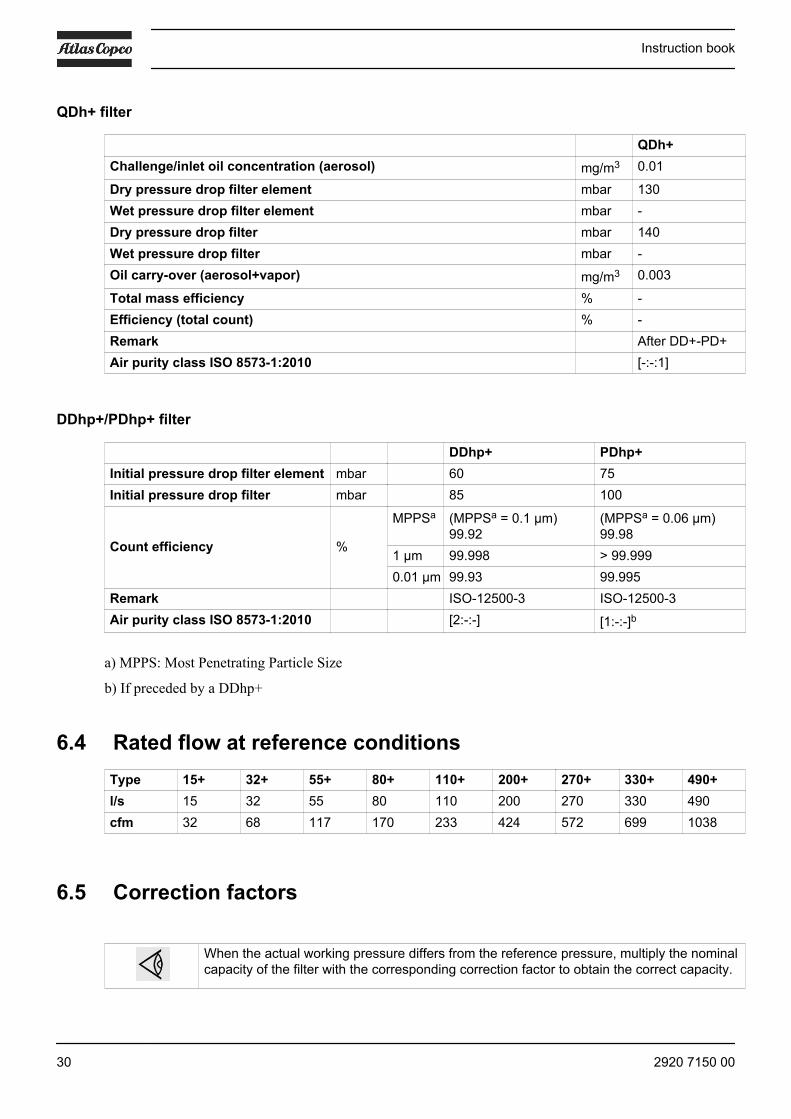
QDh+ filter
QDh+Challenge/inlet oil concentration (aerosol) mg/m3 0.01
Dry pressure drop filter element mbar 130Wet pressure drop filter element mbar -Dry pressure drop filter mbar 140Wet pressure drop filter mbar -Oil carry-over (aerosol+vapor) mg/m3 0.003
Total mass efficiency % -Efficiency (total count) % -Remark After DD+-PD+Air purity class ISO 8573-1:2010 [-:-:1]
DDhp+/PDhp+ filter
DDhp+ PDhp+Initial pressure drop filter element mbar 60 75Initial pressure drop filter mbar 85 100
Count efficiency %
MPPSa (MPPSa = 0.1 µm)99.92
(MPPSa = 0.06 µm)99.98
1 µm 99.998 > 99.9990.01 µm 99.93 99.995
Remark ISO-12500-3 ISO-12500-3Air purity class ISO 8573-1:2010 [2:-:-] [1:-:-]b
a) MPPS: Most Penetrating Particle Size
b) If preceded by a DDhp+
6.4 Rated flow at reference conditionsType 15+ 32+ 55+ 80+ 110+ 200+ 270+ 330+ 490+l/s 15 32 55 80 110 200 270 330 490cfm 32 68 117 170 233 424 572 699 1038
6.5 Correction factors
When the actual working pressure differs from the reference pressure, multiply the nominalcapacity of the filter with the corresponding correction factor to obtain the correct capacity.
Instruction book
30 2920 7150 00

Working pressure bar(e) 14 16 18 20Working pressure psig 203 232 261 290Correction factor 0.90 0.95 1 1.05
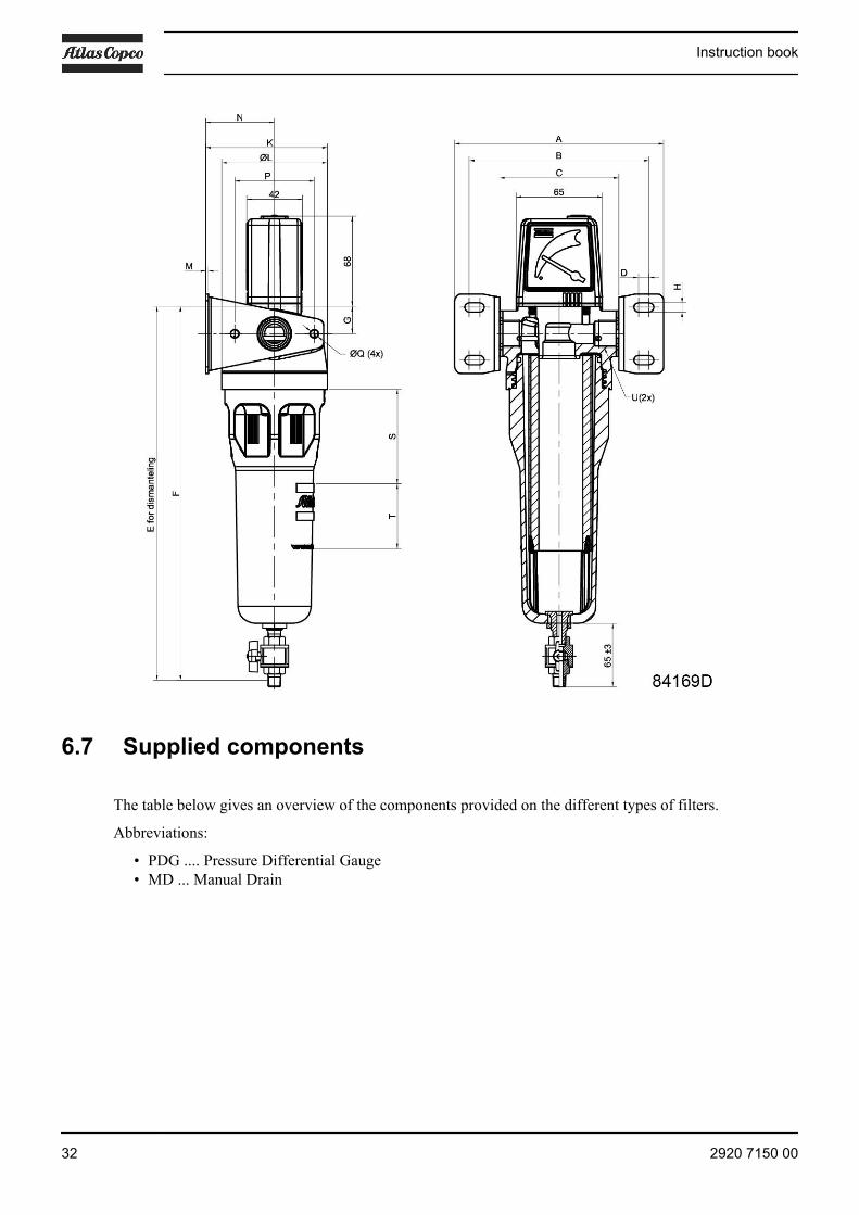
6.6 Dimensions and weightType Net
masskg
Amm
Bmm
Cmm
Dmm
Emm
Fmm
Gmm
Hmm
Jmm
15+ 1 158 136 90 8 303 228 21 7 2032+ 1.1 158 136 90 8 303 228 21 7 2055+ 1.3 158 136 90 8 358 283 21 7 2080+ 1.9 190 168 110 5 378 303 27.5 10 30110+ 2.1 190 168 110 5 418 343 27.5 10 30200+ 4.2 240 218 140 5 549 449 34 10 42270+ 4.5 240 218 140 5 632 532 34 10 42330+ 4.6 240 218 140 5 632 532 34 10 42490+ 6.9 279 251 179 8 768 618 50 12 42
Type Kmm
Lmm
Mmm
Nmm
Pmm
Qmm
Rmm
Smm
Tmm
U"
15+ 92 80 2 52 60 6.6 14 65 40 3/832+ 92 80 2 52 60 6.6 14 65 52 1/255+ 92 80 2 52 60 6.6 14 65 52 1/280+ 118 100 2 68 76 9 15 70 56 3/4110+ 118 100 2 68 76 9 15 70 56 1200+ 157.5 131 2.5 92 103 9 20 98 78 1 1/2270+ 157.5 131 2.5 92 103 9 20 100 80 1 1/2330+ 157.5 131 2.5 92 103 9 20 100 80 1 1/2490+ 183 166 2.5 100 135 11 24 159 128 2
Dimension U is G (ISO 228/1) or NPT (ANSI B1.20.1) - thread.
Dimension E indicates the space needed for dismantling.
Instruction book
2920 7150 00 31
6.7 Supplied components
The table below gives an overview of the components provided on the different types of filters.
Abbreviations:
• PDG .... Pressure Differential Gauge• MD ... Manual Drain
Instruction book
32 2920 7150 00
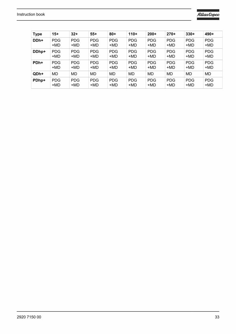
Type 15+ 32+ 55+ 80+ 110+ 200+ 270+ 330+ 490+DDh+ PDG
+MDPDG+MD
PDG+MD
PDG+MD
PDG+MD
PDG+MD
PDG+MD
PDG+MD
PDG+MD
DDhp+ PDG+MD
PDG+MD
PDG+MD
PDG+MD
PDG+MD
PDG+MD
PDG+MD
PDG+MD
PDG+MD
PDh+ PDG+MD
PDG+MD
PDG+MD
PDG+MD
PDG+MD
PDG+MD
PDG+MD
PDG+MD
PDG+MD
QDh+ MD MD MD MD MD MD MD MD MDPDhp+ PDG
+MDPDG+MD
PDG+MD
PDG+MD
PDG+MD
PDG+MD
PDG+MD
PDG+MD
PDG+MD
Instruction book
2920 7150 00 33


No.
292
0 71
50 0
0 / 2
015
- 02
- Prin
ted
in B
elgi
um
In order to be First in Mind—First in Choice® for all your qualitycompressed air needs, Atlas Copco delivers the products andservices that help to increase your business’ efficiency andprofitability.
Atlas Copco's pursuit of innovation never ceases, driven by ourneed for reliability and efficiency. Always working with you, weare committed to providing you the customized quality airsolution that is the driving force behind your business.
www.atlascopco.com