comprehensive model of first responder operations ...cope.vtt.fi/cope deliverable d3 1- conops - v3...
TRANSCRIPT

COPE – COMMON OPERATIONAL PICTURE EXPLOITATION
SEVENTH FRAMEWORK PROGRAMME
GRANT AGREEMENT No 217854
Collaborative project
Deliverable No D3.1
03/07/2009
Comprehensive Model of First Responder Operations & Concept of Operations
Authors: Patrick Grommes, TCD
Rob Hutton, BAE-ATC
Nick Colford, BAE-ATC
Work package (WP.Task): WP3.1
Deliverable No: D3.1
Delivery date (in Annex I): May, 2009
Review date (in Annex I): March, 2010
Responsible partner: TCD
Dissemination level: PU

2 (36)
D3.1
Document Change Log
Version Date Changes Responsible
0.1 20/04/2009 First Draft Patrick Grommes
1.0 16/06/2009 Preparation for delivery Patrick Grommes
2.0 29/06/2009 Pre-final edit & sequence
diagrams
Patrick Grommes
2.1 01/07/2009 Review Reinhard Hutter
2.1 03/07/2009 Review Terry Kearney, Brigade
Training Officer
(Dublin Fire Brigade
Training Centre)
3 03/07/2009 Final edit Patrick Grommes

3 (36)
D3.1
Summary
This document provides models representing the current systems and structures for incident
command. As such it represents the CONOPS of a reference system for the COPE
development process. The reference system models are provided as a set of UML diagrams.
These diagrams identify operational tasks and the actors involved and their interactions. This
document will also be used to motivate changes in the current system and it will be the basis
for a human factors analysis and assessment of the proposed set of COPE technologies.

4 (36)
D3.1
Contents
Summary .....................................................................................................................3
1 Scope .....................................................................................................................9
1.1 Reference Documents ....................................................................................9
1.2 Objectives of this Document .........................................................................10
1.3 System overview...........................................................................................11
2 Current system and situation................................................................................12
2.1 Background, objectives, and scope ..............................................................12
2.2 Operational policies & constraints – Incident Command Structures..............13
2.3 Description of the current situation................................................................14
2.3.1 Incident Command Use Cases: Organising the incident ground........14
2.3.2 Incident Command Use Cases: Tactical Mode & Risk Assessment ..17
2.3.3 Incident Command Use Cases: Personnel Management ..................19
2.3.4 Incident Command Use Cases: Resource Management ...................20
2.3.5 Incident Command Use Cases: Command and Control devolution ...21
2.3.6 Incident Command Use Cases: Coordination with other agencies ....22
2.3.7 Coordination among agencies: FRS and EMS use cases .................23
2.3.8 Coordination among agencies: FRS and police use cases................24
2.3.9 FRS activities: Fire Attack Use Cases ...............................................25
2.3.10 FRS activities: Water management use cases...................................26
2.3.11 FRS activities: Search and rescue use cases....................................27
2.3.12 FRS activities: Hand over use cases .................................................28
2.4 Modes of operation for the reference system................................................29
2.5 User classes and other involved personnel ..................................................29
2.5.1 Incident Command Class Diagrams: Size Up ....................................29
2.5.2 Incident Command Class Diagrams: Incident Ground Management .31
2.5.3 Incident Command Class Diagrams: Coordination with non-FRS agencies.............................................................................................32
2.5.4 Interactions among user classes........................................................33
3 Justification for and nature of changes .................................................................35
3.1 Justification of changes.................................................................................35
4 Concepts for the proposed system.......................................................................35
5 Operational scenarios...........................................................................................35
6 Summary of impacts.............................................................................................36
7 Analysis of the proposed system..........................................................................36

5 (36)
D3.1
Abbreviations
BA Breathing Apparatus
BA ECO Breathing Apparatus Entry Control Officer
C2 Command and Control
CONOPS Concept of Operations
COP Common Operational Picture
COPE Common Operational Picture Exploitation
CS Command Support
CSO Command Support Officer
DO District Officer
EMS Emergency Medical Services
EPA Environmental Protection Agency (Ireland)
FF Fire Fighter
FR First Responder
FRS Fire and Rescue Services
HazMat Hazardous Material
HF Human Factors
IC Incident Commander
ICP Incident Command Post
ICS Incident Command Structure
ICT Information and Communication Technology
KSM Knowledge Space Model
OC Operations Commander
PDA Pre-Determined Attendance
PM Paramedic
PO Police Officer
RTA Road Traffic Accident
SC Sector Commander
SME Subject matter expert (usually from an end user organisation)
SMO Senior Medical Officer
SPO Senior Police Officer
SOP Standard Operating Procedures
UML Unified Modelling Language
WP Work Package

6 (36)
D3.1
Glossary of terms
(personnel and structures related to Incident Command)
• BA Emergency Team – on stand by in case of an accident
• BA Entry Control Officer (BA ECO) – a firefighter who is responsible for
the safety of all BA wearers on his BA Entry Control Board
• BA Team – a pair of BA wearers, with one Team Leader
• BA Team Leader – a BA wearer with responsibility for leading a BA
Team
• BA Wearer – anyone wearing BA
• Command Support Officer (CSO) – firefighter (or higher ranking officer
dependent on scale of the incident) designated to support the IC, especially
with communications to Control Centre; reference point for additional
appliances, manages information flow to and from the IC, records
information, .e.g. on IC board or in command wallet, assists IC in liaison
with other response agencies and third parties, arranges and manages relief
and welfare measures
• Command wallet – used in many UK FRS brigades; functionality
comparable to IC board but e.g. includes reference documentation, too
• Control Centre – The Dublin Fire Brigade Control Centre e.g. takes
emergency calls and dispatches the response units. As an incident
develops over time, the control centre can be contacted e.g. in order to
request additional resources or to upgrade the incident and alert more
senior officers.
• Firefighter – any FRS personnel; generic term, used in lieu of a specific
role term.
• Hose Team – generic term for firefighters with a hose; should be used for
external use only as BA Teams should always have a hose too
• Incident Commander (IC) – officer in charge of the Incident
• Incident Command Board (IC board) – used for example in many Irish
FRS brigades; whiteboard with predefined fields to record e.g. incident
ground information such as tactical mode, sectors, personnel on scene,
drawings and sketches of the incident ground
• Operations Commander (OC) – a firefighter put in charge of an
“operational” area, which may include several sectors; reports directly to
the IC
• Paramedic (PM) – generic term for an actor with primary medical
responsibility for casualty care, triage etc. (or EMT - Emergency Medical
Technician)
• Police Officer (PO) – generic term of an actor with primary policing
responsibility (crowd/bystander control; Incident Ground security; traffic
flow etc).
• Pump Operator – operates the pump on an appliance
• Sector – sectorisation allows the IC to delegate areas of responsibility
(either geographic/spatial or functional) to other experienced personnel;
sectorisation can be numerical with Sector 1 being the area where the first
units arrived and other sectors being assigned clockwise around the
structure on fire. Functional sectors can include a water sector, responsible

7 (36)
D3.1
for managing and securing water supply or a BA (breathing apparatus)
sector responsible for maintaining BA equipment and having relief crews
on stand by.
• Sector Commander (SC) – officer designated as responsible for a sector
• Senior Medical Officer (SMO) – the ambulance-person in charge of the
medical effort; interacts directly with the Incident Commander; may be the
Incident Commander for medical; non-rescue/fire incidents
• Senior Police Officer (SPO) – the police-person in charge of the police
effort; interacts directly with the IC; may be the IC for non-medical, non-
rescue/fire incidents

8 (36)
D3.1
List of Figures
Figure 1. ICS at incidents involving 8+ appliances (here fire in chemical plant). 11
Figure 2. Unified Command and the COPE system. 13
Figure 3. Use Case Diagram: Organising the incident ground. 15
Figure 4. Tactical Mode and Risk Assessment use cases. 17
Figure 5. Manage Personnel Use Cases. 19
Figure 6. Resource Management Use Cases. 20
Figure 7. Use Cases regarding coordination with other agencies. 21
Figure 8. C2 devolution. 22
Figure 9. FRS and EMS use cases. 23
Figure 10. Use cases for FRS – police coordination. 24
Figure 11. Fire attack use cases. 25
Figure 12. Water management use cases. 26
Figure 13. Search and Rescue use cases. 27
Figure 14. Hand over use cases. 28
Figure 15. Incident Command Classes: Size Up. 29
Figure 16. Incident Ground Management: Class Diagram. 31
Figure 17. Coordination with other agencies: Class diagram. 32
Figure 18. Incident Size-Up: Sequence diagram. 33
Figure 19. Incident Size-Up upon arrival: Sequence diagram. 34

9 (36)
D3.1
1 Scope
The task of WP3.1 was to provide a model of current operations, to identify
stakeholders in these operations and to build a concept of operations (CONOPS)
out of this. To this end, this COPE CONOPS document describes Incident
Command (IC) systems that are being put in place at any incident that requires
attendance from Fire and Rescue Services (FRS). The system description aims to
be as generic as possible, but will have to take into account particularities of FRS
in the different nations and regions that have participated in the COPE field
studies. Crucial aspects and deficiencies of IC will be identified in this document.
It will also indicate steps which should be taken in order to establish and maintain
a Common Operational Picture (COP) within the FRS as well as among FRS and
other emergency response agencies.
In line with objectives and usage of CONOPS documents in systems engineering
(IEEE standard 1362-1998) it is appropriate to broaden the scope of the COPE
CONOPS beyond a model of the current system. To facilitate this, this document
contains a section that will be gradually amended as the COPE development
process continues. It will deal with the proposed COPE solutions for improving
and maintaining an appropriate Common Operational Picture on the incident
ground and how these solutions transform the current situation into a COPE-
improved system. In doing so, findings of this document will be carried over into
WP3.3 and WP4. This deliverable documents the state of work achievable until
now. Updates depending on the coming work in COPE (technology mapping,
scenarios etc.) will be provided as amendments.
1.1 Reference Documents
This document takes IEEE standard 1362-1998 as a basic methodological starting
point. However, due to the nature of the system being described not all
specifications of the standard are applicable.
This document is closely linked to COPE D2.1 “Use Case Descriptions” and
COPE D3.2 “End User Requirements”.
Other documents / sources include:
• Alan V. Brunacini (1985). Fire Command. National Fire Protection
Agency, Quincy/MA.
• Dublin Fire Brigade Incident Command Training Material
• Feuerwehr-Dienstvorschrift 100 (FwDV100): Führung und Leitung im
Einsatz: Führungssystem. Beschlossene Fassung des AFW: 10.03.99
(German Command and Control System and Procedures for FRS)
• Irish Framework for Major Emergency Management (available at:
http://www.environ.ie/en/LocalGovernment/FireandEmergencyServices/E
mergencyPlanning/PublicationsDocuments/FileDownLoad,796,en.pdf; last
accessed 03/07/2009)
• UK Fire Services Manual, Vol. 2, Fire Service Operations, Incident
Command issued by HM Fire Service Inspectorate, Publications Section
(2002)
• US Unified Command documents (e.g. http://www.osha.gov/SLTC/
etools/ics/what_is_uc.html; last accessed: 03/07/2009).

10 (36)
D3.1
1.2 Objectives of this Document
The primary addressees of this CONOPS document are technology developers in
WP5 of the COPE project, CESS as evaluation and demonstration work package
leader (WP6), and WP4, the technology mapping process, the interface between
human factors and technology development. The human factors work packages
WP2 and 3 have been main contributors to this document.
This CONOPS document serves several purposes:
- to present a user-centred view of IC systems
- to identify candidate areas for improvement in current IC systems
- to support a shared understanding of IC systems among COPE partners
- to provide technology developers with a view of information flows within the
FRS IC system and among FRS and other agencies’ systems
- to enable technology developers to communicate functionalities and benefits
of their proposed solutions in an operationally valid context
- to enable subject matter experts / end users to validate COPE assumptions and
proposals
- to provide a context for testing and evaluating scenarios.

11 (36)
D3.1
1.3 System overview
The purpose of the system being developed is to support IC functions and more
specifically to enable Incident Commanders to receive and send relevant
information from and to relevant locations and actors on the incident ground and
to integrate this information into a Common Operational Picture among all
relevant response agencies.
Figure 1. IC structure at incidents (here fire in chemical plant) involving 8+ appliances (diagram
courtesy of and Dublin Fire Brigade Training Centre).1
An example view of actors and lines of communication is given in figure 1 above.
The current incident command structures and the various tools and procedures
that will be described further down in this document together with the respective
information flow and content will be the reference system for the COPE
development process. The COPE project takes this reference system and the use
of this system by relevant actors as staring point for technology development. The
proposed improved system will consist of technology components and subsystems
developed and integrated in WP5. Any proposed solution shall better support the
existing procedures and ways of working.
1 Key to abbreviations: ACFO – Assistant Chief Fire Officer (2
nd highest rank in Dublin Fire Brigade); CH1 etc.
– radio channels in use between specific actors; CSA – command support appliance, i.e. fire engine exclusively
used for CS purposes; CSU – Command support unit, i.e. purpose-fitted CS vehicle; D51 etc. – Appliance with
call sign; DO Echo etc. – District Officers of Echo etc. districts; MOBI – mobilisation officer, i.e. officer in
charge at the control centre; RCC – regional control centre; SO – Station Officer, i.e. officer in charge of a fire
station; S/Off – Sub-Officer, i.e. 2nd in command to SO; TTL – turn table ladder; all other abbreviations see list
following the table of contents.

12 (36)
D3.1
2 Current system and situation
2.1 Background, objectives, and scope
According to the Description of Work , a CONOPS for COPE should describe
emergency response as a coordinated effort of all relevant response agencies and
other authorities. Such a concept by definition entails coordination among
agencies at various command and control levels. Concepts to guide this
coordination exist in various formats. One starting point for a generic CONOPS
could be an established concept such as Unified Command.
The concept of Unified Command has been developed in the United States in the
1980s in the aftermath of a series of wildfires that revealed serious shortcomings
in the interaction and coordination among response agencies at all levels – local,
regional, and federal. The core idea has been to provide structures and procedures
for inter-agency coordination on the incident ground but also at super-ordinate
levels. In the US model this entails that representatives of all relevant response
agencies meet at an off-site location and devise overall plans and objectives in
response to the incident. These representatives have to be empowered by their
agencies to commit resources to the achievement of the set objectives and to
exercise command within in their agencies that allows enacting measures to
achieve the objectives. Decisions and directives of this overarching command
centre are communicated down to the incident ground by the individual agencies’
representatives to their incident commanders. These are then responsible for
acting on the directives in coordination with the on-site incident command and the
other agencies.
The Irish Framework for Major Emergency Management follows a similar
approach – as do those of many other countries. However, e.g. as the analysis of
German procedures has shown, considerable differences remain and therefore the
COPE CONOPS can only be an abstraction based on findings in participating
response agencies. And any proposal for a CONOPS, a COP, COPE C2 systems
etc. will have to be flexible and adaptable to national and regional specificities
when it comes to live applications. Two important features of the Irish Emergency
Management Framework are worth mentioning here. There is firstly the Lead
Agency Concept. This concept enables response agencies to quickly decide upon
the lead agency at an emergency site, which then also implicates what agency will
be lead agency at all other levels. Lead agencies are pre-nominated in most cases,
so that there is no need for lengthy decision-making processes. With regard to the
two COPE scenarios, the RTA with chemical spill and the factory fire potentially
involving hazardous materials, the local authority and thereby fire services will be
lead agencies. This then implies that at highest level the Department of the
Environment will be the lead department. The picture changes if we assume a
terrorist attack to be underlying the fire scenario. In this case, An Garda Síochána
(Police) and the Department of Justice or in the German case the Ministry of the
Interior become lead agencies. Lead agencies in this concept assume overall on-
site incident command and are also responsible for dealing with long-term
consequences and response measures. The other important concept is that of
establishing on-site, local, regional, and national emergency coordination centres.
The main logic of this concept is that all response activities should be local and
higher level coordination centres have a supporting and monitoring role. This
implies a bottom-up approach. Top-down emergency management can of course
13 (36)
D3.1
be required at any stage but as a default it only occurs in case of major
catastrophes like nuclear accidents, infectious epidemic/pandemic scenarios.
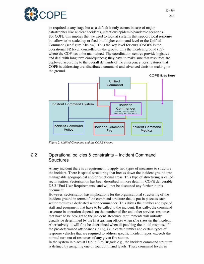
For COPE this implies that we need to look at systems that support local response
but allow to be scaled up or feed into higher command level or the Unified
Command (see figure 2 below). Thus the key level for our CONOPS is the
operational FR level, controlled on the ground. It is the incident ground (IG)
where the COP has to be maintained. The coordination centres provide logistics
and deal with long term consequences; they have to make sure that resources are
deployed according to the overall demands of the emergency. Key features that
COPE is addressing are: distributed command and advanced decision making on
the ground.
Figure 2. Unified Command and the COPE system.
2.2 Operational policies & constraints – Incident Command Structures
At any incident there is a requirement to apply two types of measures to structure
the incident. There is spatial structuring that breaks down the incident ground into
manageable geographical and/or functional areas. This type of structuring is called
sectorisation. Sectorisation has been described in more detail in COPE deliverable
D3.2 “End User Requirements” and will not be discussed any further in this
document.
However, sectorisation has implications for the organisational structuring of the
incident ground in terms of the command structure that is put in place as each
sector requires a dedicated sector commander. This drives the number and type of
staff and equipment that have to be called to the incident. Basically, the command
structure in operation depends on the number of fire and other services resources
that have to be brought to the incident. Resource requirements will initially
usually be determined by the first arriving officer when s/he sizes up the incident.
Alternatively, it will first be determined when dispatching the initial response if
the pre-determined attendance (PDA), i.e. a certain umber and certain types of
response vehicles that are required to address specific incident types, exceeds the
normal turn out of resources of any given fire station.
In the system in place at Dublin Fire Brigade e.g., the incident command structure
is defined by assigning one of four command levels. These command levels in

14 (36)
D3.1
turn are defined by the number of FRS vehicles attending to the incident.
Command Level 1 applies to incidents with a maximum attendance of two FRS
appliances. In this case a Station Officer, i.e. an officer who is in charge of one
fire station, will be incident commander. If the incident requires only one
appliances even a Sub-Officer, i.e. an officer in charge of an appliance crew, can
be incident commander. If two or more appliances are required a District Officer
(DO), i.e. an officer in charge for a fire district comprising of several fire stations,
will be the Incident Commander. The DO’s vehicle will become the Incident
Command Post (ICP). This will be Command Level 2. Command Level 3 will be
declared at incidents requiring five or more appliances. A Third Officer, i.e. an
officer with management functions beyond district level, will be Incident
Commander. This role is unique to Dublin Fire Brigade. Command Level 4 – see
also figure 1 above for an example – will be declared when eight or more
appliances are required. In such a case an Assistant Chief Fire Officer or the Chief
Fire Officer will be Incident Commander. A purpose-built Incident Command
Unit, i.e. a truck carrying a small scale but fully functional operations control
room, will be the ICP. This will be the case for any incident requiring six or more
appliances. It also has to be noted that at large scale incidents there will most
likely be a number of DOs at the scene to take on Operations Command functions,
i.e. they will for example be intermediaries between IC and Sector Command. A
District Officer or a Third Officer will also be in charge of overall Command
Support at level 4 incidents. Command Support mainly deals with
communications to the control centre, other agencies and media and the public.
As a general rule, the most senior officer at the scene will have overall
responsibility for the incident. Furthermore, a higher ranking officer can be called
to the scene whenever the current Incident Commander assumes this to be
appropriate. However, in both cases the more senior officer may decide not to take
on Incident Command. If s/he takes on Incident Command, then the
corresponding command level will have to be declared and communicated to the
control centre and to all sectors and sector commanders.
In summary, the Incident Command Structure is pre-defined to a certain degree in
order to avoid decision-making difficulties or even power struggles and
consequential delays at the scene of the incident. It also clearly assigns
responsibilities. At the same time, the structure is flexible and allows building up
or sizing down the response as required according to the development of the
incident. Additionally, declaration of a specific command level gives an indication
of the dimensions and seriousness of the incident to everybody involved in
responding to it.
2.3 Description of the current situation
This section provides an overview of generic system activities by means of a set
of UML use case diagrams. Selected use cases from these diagrams will be
framework for the COPE technology development; in other words, any of the
solutions proposed by COPE technology developers should address at least one of
the use cases depicted in the diagrams provided in this chapter.
2.3.1 Incident Command Use Cases: Organising the incident ground
An actor in UML terms can be a person, an organisation, or any system or object
that is involved in the activity captured by the use case. In the diagrams in this

15 (36)
D3.1
section actors have to be understood as being potentially involved, i.e. the actors
shown indicate the maximum number of actor types2 per use cases.
Figure 3. Use Case Diagram: Organising the incident ground.
The use case “sizeUpSituation” potentially involves all the actors depicted above.
In this use case diagram representatives of utility companies, the Environmental
Protection Agency (EPA) and the assigned company keyholder plus a
representative who is knowledgeable about hazardous materials at an industrial
site provide information to the Incident Commander. The Incident Commander
2 Actors in use cases can be instantiated by one or a number of physical objects or persons in reality, i.e.
“SectorCommander” in a use case can be instantiated as Sector Commander Sector 1 – 4 or Sector Commander
Water, Sector Commander Decontamination etc.

16 (36)
D3.1
determines on the basis of this information what resources will be required
including and exceeding those available upon arrival on scene.
The “notification” use case indicates that e.g. a Caller3 may notify the Control
Room of an incident and on the basis of this information company representatives
will be informed.
The “defineCommandLevel” use case indicates that on the basis of information
available while en route or upon arrival the current incident commander decides
on the command level and if necessary informs the Control Room of any changes.
The decision will amongst others be guided by standard operating procedures
(SOPs).
The “informPublic” use case indicates that based on knowledge available at early
stages and at any time from there on there may be a need to inform the public of
any threats and hazards. The incident commander takes this decision and
communicates it to police and the control room. The control room maybe an
intermediary between police and incident command if not already on scene.
The “sectorise” use case indicates that – in most cases – the incident ground will
have to be divided into sectors to allow for appropriate command and control and
a manageable incident command structure.
The “setUp…” use cases indicate that depending on the situation on the incident
ground dedicated areas will have to be set up for certain activities. Not all of these
use cases may be required in a single scenario, and also the requirement for
setting up a specific area may only arise later in the lifetime of an incident. In this
sense use case diagrams are insensitive to time and sequence.
3 The “Caller” actor symbol is shown in red, because this actor is either still to be defined in a class diagram or
may need to be specified otherwise.

17 (36)
D3.1
2.3.2 Incident Command Use Cases: Tactical Mode & Risk Assessment
Figure 4. Tactical Mode and Risk Assessment use cases.
The risk assessment and tactical mode use cases indicate that the incident
commander has to perform dynamic risk assessment on an ongoing basis and has
to assign an appropriate tactical mode to relevant sectors. Risk assessment is
being done on the basis of information made available to the incident commander
and captured on the incident command board. In some cases risk assessment
includes assessing the risk of domino effects or cascading effects. For example, in
chemical fire events on the incident ground may have effects on neighbouring

18 (36)
D3.1
sites and may lead to adverse events there. In some cases information about such
potential effects is laid down in documentation such as a folder on hazardous
materials and chemical hazards per industrial site. The tactical mode use cases
involve sector commanders and/or operations commanders not only as recipients
of mode assignments, but they can declare a tactical mode for their sectors
autonomously if the situation requires.
The “supportInfoTransferCS” and “supportInfoTransferOC” use cases indicate
that depending on the size of the incident and the required command structure
Operations Command (OC) and/or Command Support (CS) may require
assistance by dedicated firefighters in communicating with other actors. The
specific solutions for this issue appear to be different as per country or region. An
operations commander will be assigned if the number of lines of communication
for the incident commander is no longer manageable. The OC then becomes an
intermediary between incident command and sector commanders. In the same
way CS manages communication to other agencies on the incident ground and off
site.

19 (36)
D3.1
2.3.3 Incident Command Use Cases: Personnel Management
Figure 5. Manage Personnel Use Cases.
The right hand side of figure 5 mirrors the use cases in the risk assessment and
tactical mode section. The incident commander’s role is more about setting
objectives and monitoring on site activities than assigning specific people to
specific tasks – with the exception of assigning command and control tasks. In
most cases default tasks per individual firefighter will be assigned at the start of
the shift, e.g. BA wearer, pump operator. The incident commander also has to
have an oversight of who is where on the incident ground. This information is
captured on the incident board. The Nominal Roll Board indicates what FRS
personnel with what qualifications is on site, whereas Visitor Roll Boards show
which non-FRS personnel are on site.

20 (36)
D3.1
2.3.4 Incident Command Use Cases: Resource Management
Figure 6. Resource Management Use Cases.
The resource management use cases depend on information from the frontline.
The incident commander – via sector commanders – has to determine the
resources status and has to take action to close gaps in resource demand. The
control centre may become involved in this if resources have to be ordered from
off site sources within the FRS or even from other agencies.

21 (36)
D3.1
2.3.5 Incident Command Use Cases: Command and Control devolution
Figure 8. C2 devolution.
The use cases in figure 8 indicate that wherever possible devolution of command
and control will be implemented. They also indicate that the incident commander
does not always receive first hand information, but information that has been
filtered on its way up the command chain. The radio operator actors – who may
not be roles assigned in all countries or regions – indicate that lower level
command may also be supported by designated actors.
22 (36)
D3.1
2.3.6 Incident Command Use Cases: Coordination with other agencies
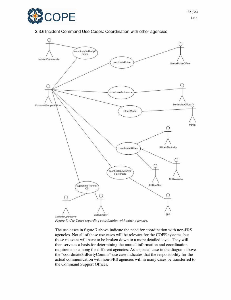
Figure 7. Use Cases regarding coordination with other agencies.
The use cases in figure 7 above indicate the need for coordination with non-FRS
agencies. Not all of these use cases will be relevant for the COPE systems, but
those relevant will have to be broken down to a more detailed level. They will
then serve as a basis for determining the mutual information and coordination
requirements among the different agencies. As a special case in the diagram above
the “coordinate3rdPartyComms” use case indicates that the responsibility for the
actual communication with non-FRS agencies will in many cases be transferred to
the Command Support Officer.
23 (36)
D3.1
2.3.7 Coordination among agencies: FRS and EMS use cases
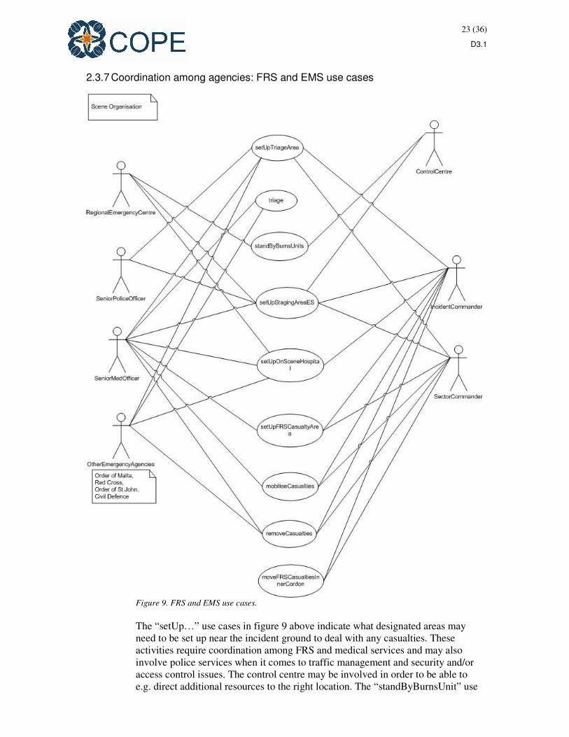
Figure 9. FRS and EMS use cases.
The “setUp…” use cases in figure 9 above indicate what designated areas may
need to be set up near the incident ground to deal with any casualties. These
activities require coordination among FRS and medical services and may also
involve police services when it comes to traffic management and security and/or
access control issues. The control centre may be involved in order to be able to
e.g. direct additional resources to the right location. The “standByBurnsUnit” use

24 (36)
D3.1
case may be a special case as it requires higher level emergency management to
become involved. Some of the use cases above may directly affect only the
medical site, e.g. triage, or the FRS side, e.g. moving fire services casualties from
the inner cordon, but it will have to be determined how much the other agency
may have to know or may wish to know about these activities. The mobilisation
and removal use cases involve the medical services, but to a different degree
depending on the situation on the incident ground. Depending on the risk
assessment it may either be too dangerous for non-FRS services to enter the inner
cordon for rescue services or to the contrary the status of a casualty may require
medical attention despite other risks.
2.3.8 Coordination among agencies: FRS and police use cases
Figure 10. Use cases for FRS – police coordination.
From an FRS point of view the main tasks for police will be traffic management,
security, cordoning and dealing with the public and media. However, police is not
supposed to be close to the inner cordon, i.e. near the hot zone in a fire incident
and vice versa the fire services may not be involved at all in e.g. evacuation orders
which may require involvement of higher levels of emergency management.
25 (36)
D3.1
2.3.9 FRS activities: Fire Attack Use Cases
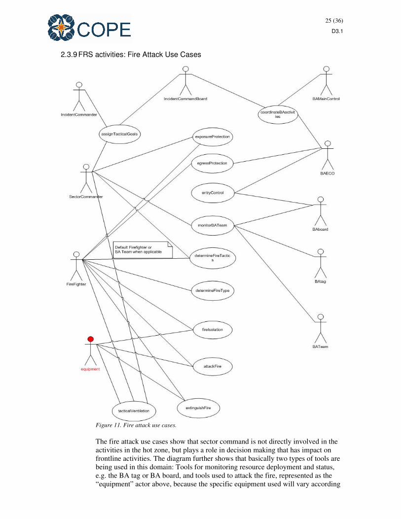
Figure 11. Fire attack use cases.
The fire attack use cases show that sector command is not directly involved in the
activities in the hot zone, but plays a role in decision making that has impact on
frontline activities. The diagram further shows that basically two types of tools are
being used in this domain: Tools for monitoring resource deployment and status,
e.g. the BA tag or BA board, and tools used to attack the fire, represented as the
“equipment” actor above, because the specific equipment used will vary according

26 (36)
D3.1
to the type of fire and the environment among other factors. The diagram also
indicates that in the current situation there is no online monitoring of equipment
use and deployment. This is becomes evident by the fact that currently equipment
can be borrowed from appliances across fire stations. Missing equipment then will
be redistributed after the event.
2.3.10 FRS activities: Water management use cases
Figure 12. Water management use cases.
The water management use cases indicate that this is an area of coordination
across sectors, but between a limited set of actors. It is however noteworthy that
not every actor has to know exactly how any other actor goes about his/her
specific task. For this reason, for example, there is a “maintainWaterSuppply” use
case and a “maintainFlowRate” use case. Firefighters have a vital interest in being
supplied with a sufficient amount of water. So they have a stake in this use case,
but they don’t need to know about the source of the water. On the other hand the
sector commander “water” has to make sure that there is no interruption in water
supply for maintaining the flow rate, and by this token performing tasks in the
operational sector, is not in his/her remit. This is what frontline firefighters and
firefighter deployed as pump operators have to deal with using the appropriate
equipment. Additionally, coordination between sector command at operational
and functional level and incident command is crucial here, because different

27 (36)
D3.1
tactical goals require specific usage of water. For example, when pushing back the
fire ands creating a stable environment for search and rescue, smaller amounts of
water may have to be used to avoid developing too much steam and thus
conditions of high temperatures and low visibility. On the other hand, when the
operations are in defensive mode and water is applied to cool structures on fire as
well as adjacent exposures then much more water maybe required. Therefore
decisions at IC level have immediate impact on operations related to water
management.
2.3.11 FRS activities: Search and rescue use cases
Figure 13. Search and Rescue use cases.
The search and rescue use cases are similar to the fire attack use cases in some
respects. There are resource monitoring and coordination functions that happen
alongside the operational tasks and in some cases they enable or safeguard them
e.g. by providing egress protection for search and rescue crews – who in most
cases would be BA wearers and as such be involved in the BA side of the use
cases in figure 13. Beyond this , this diagram illustrates that the incident
commander sets the overall frame for the operations that then has to be translated

28 (36)
D3.1
into tasks by sector commanders. These tasks, here the diverse search and rescue
tasks, then have to be executed by firefighters on the frontline. What this also
shows is that that the incident commander has to rely on information transferred
up the command line as a basis for his/her decision making and risk assessment.
Additionally, it becomes clear that some scope for decision making is delegated to
the sector command level as it is here that real-time, first hand knowledge is
available.
2.3.12 FRS activities: Hand over use cases
Figure 14. Hand over use cases.
The use cases in figure 14 above indicate that at certain stages of the incident
lifetime hand over between incoming and outgoing crew members have to take
place. These activities are formalised to some degree with some variance at the
different levels. The BA board and the incident command board play a crucial role
in documenting crew deployment and status features of the incident.
29 (36)
D3.1
2.4 Modes of operation for the reference system
The Incident Command System essentially consists of people-orientated / people-
run processes. One of its main objectives is to support decision-making at
different levels and communicating these decisions to the appropriate addressees.
The underlying information transfer occurs along pre-defined channels, but not
necessarily in a pre-defined or standardised manner. Much of it is remote, but
synchronous person-to-person communication via basic ICT technology (radio).
A major problem of this system is that it can easily break down, because of
technology failure, but also because of environmental and human factors.
Receiving and processing information in a highly dynamic and often noisy and
potentially dangerous environment is no simple task. However, removing this task
to a safer and more stable environment, e.g. an incident command vehicle, may
cut off first hand information sources. Further, providing information from the
frontline is subject to an unstructured filtering process, because constraints
imposed e.g. by equipment or exhaustion may lead to incomplete information
transfer.
2.5 User classes and other involved personnel
This section describes who the actors are which are affected by the current
incident command system. This includes every person who contributes to the
information flow in the current system. Users of products and solutions that will
be part of the COPE systems and their way of system usage will be identified
during the COPE development process and will be included in the internal
iteration of this document as outlined in section 1 above. The main body of this
section comprises of class diagrams that are based on the use cases of section 2.3.
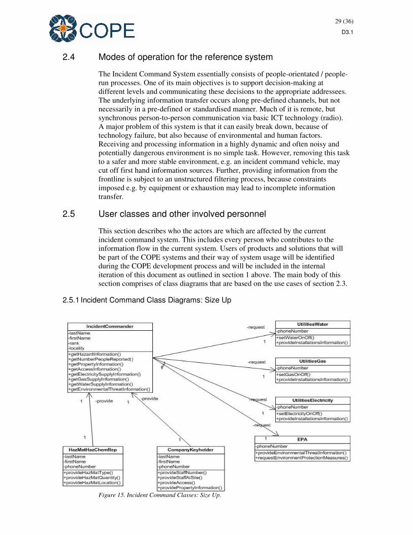
2.5.1 Incident Command Class Diagrams: Size Up
Figure 15. Incident Command Classes: Size Up.

30 (36)
D3.1
The diagram in figure 15 describes at a high level what relationships exist
between classes of actors in the emergency response system when being involved
in the size up use case. Each class is characterised by a name, e.g. incident
commander; a list of attributes, i.e. distinguishing features, in the second
compartment and a list of operations, i.e. actions performed by instances of the
class. Attributes and operations determine information items that will be
processed in the system and they may give indications of what technology can do
to support operations. What actually needs support by new systems and
technologies and how this support should be given or implemented has been
described to some degree in the user requirements document D3.2 and will be
specified further in the technology mapping process.
31 (36)
D3.1
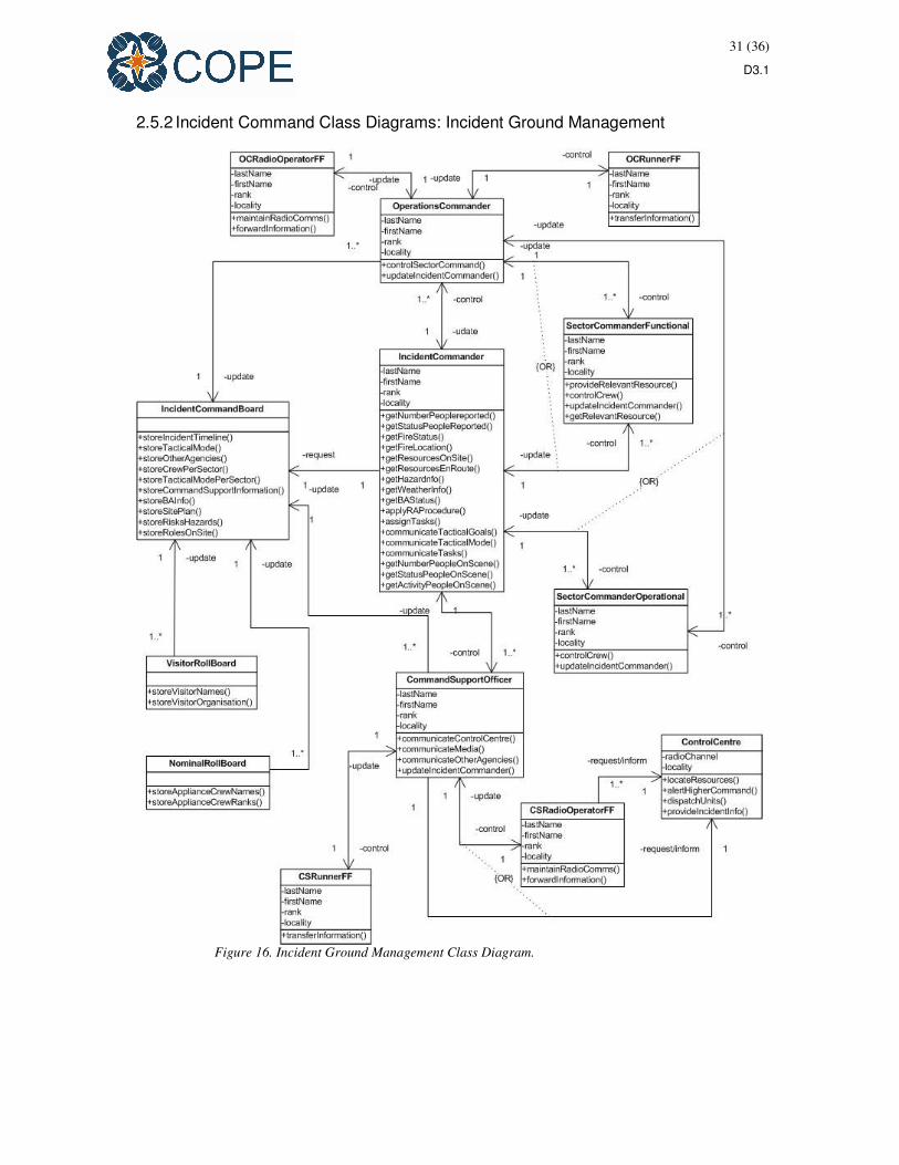
2.5.2 Incident Command Class Diagrams: Incident Ground Management
Figure 16. Incident Ground Management Class Diagram.

32 (36)
D3.1
The diagram in figure 16 captures all classes involved in the incident command
use cases and their basic relationships. Obviously, not all operations will be
activated in each use case, but since this is a static view of the system they can be
represented in one overarching diagram rather than very similar diagrams for each
use case. The “or” relation between some of the links indicates that depending on
the set up of the incident command system in each individual incident only one of
the links exists at any point in time.
2.5.3 Incident Command Class Diagrams: Coordination with non-FRS agencies
Figure 17. Coordination with other agencies: Class diagram.
The diagram in figure 17 follows the same logic as the previous one. It captures
classes of actors and their relationships in a generic way – this time regarding the
FRS and other agencies coordination activities.

33 (36)
D3.1
2.5.4 Interactions among user classes
This section describes – by means of two exemplary case – how the different
actors interact with each other and in what sequence. However, any sequence
indicated here can vary according to the circumstances of a specific real life
incident. The picture provided here is generic and focuses on interaction and
exchange more than on the exact chronological sequence of units of exchanges. In
addition to the exchanges and their main topics, this section provides information
on what communication tools and channels are used in certain cases and what
information items are associated with some exchanges. Thus, this section also
gives some indication on the basic information flow on the incident ground, too.
Further diagrams of this type will be produced during technology development for
those use cases that will be associated with specific COPE solutions. These
diagrams will be documented in internal reports.
Figure 18. Incident Size-Up: Sequence diagram
4.
The initial phases of response to an incident reflect some of the main tasks of the
incident commander throughout the incident lifetime. Basically, the incident
commander has to gather as much information as possible about the incident and
formulate the appropriate response tactic on the basis of this information. For the
initial stages of incident response this activity is called “size-up”. During size-up
the IC has to establish an initial picture of the situation and deploy the
immediately available resources as efficient as possible. S/he also has to get a first
4 The notation of sequence diagrams is to be read as follows: The top line indicates all actors potentially involved
in this sequence of interaction. The dotted lines below each actors represent their lifelines. Whenever a box is
shown on a lifeline, this indicates that the actor becomes active; usually in response to a call sent from another
actor. Dotted arrows indicate that this message is a response to a call. In addition to standard UML notation, text
boxes give further detail on information items (left hand side of the diagram) and communication tools used
(right hand side of the diagram).

34 (36)
D3.1
understanding of the amount of additional resources required and whether or not
the command level has to be changed.
As figure 18 indicates an incident response begins – for the crews at a particular
station – with mobilisation on the basis of the call out docket. At the same time
the control centre may alert additional non-FRS actors to the incident. The
incident commander engages in size-up as soon as possible and normally uses the
time en route to the incident to gather additional information – with the help of the
control centre – and to brief his crews on the initial steps s/he plans to take.
Figure 19. Incident Size-Up upon arrival: Sequence diagram.
The various exchanges displayed in figure 19 may not all happen at the initial
stage of an actual incident, because they can quickly become time consuming and
time is very short at this stage of response. Most of what is described in figure 19
takes place within the first two to five minutes after arrival. This clearly indicates
that we have to assume very rapid decision making at this stage and considerable
variation to the picture above. For example, some of the command that will be
made via radio at later stages may be shouted at this stage, because the actors are
still close together. Similarly, entries on the IC board may be held back until there
is time to actually set it up and to write down the required information items.
Against this background, figure 19 describes an idealised picture and at the same
time a picture of the activities undertaken as the incident develops. These
activities and exchange provide crucial input to the ongoing risk assessment and
subsequent potential modification of tactics by the incident commander. In
essence, the information exchange above capture the IC’s task of gathering all
relevant information on the so-called fire ground factors (see Brunacini 1985,
35 (36)
D3.1
pp.47). These factors concern the building on fire, the type of the fire itself,
occupancy or workforce present or expected to be present at a site or building,
potential threats and life hazards to occupants and fire crews, the geographical
arrangements, available resources, appropriate actions, and any special
circumstances.
3 Justification for and nature of changes
3.1 Justification of changes
This part of the document has become redundant for reporting purposes as the
deliverable D3.2 “End User Requirements” has already been delivered.
Remaining topics for this section of a CONOPS document include: a description
of desired changes, priorities among changes, and changes considered but not
included. These topics are being addressed at the time of writing in working
groups set up under the auspices of WP4. Each of the working groups is dedicated
to a specific field of technology and is co-led by a human factors and a technology
expert. Results of this work will be reported in WP4 deliverables. Any issues that
can not be reported in those deliverable swill be taken into account for the internal
iteration of this document in so far as they are required to understand the nature of
the proposed COPE systems.
4 Concepts for the proposed system
As indicated in section 1, this document deals with the current system only and as
such provides necessary input to the COPE development process. However, as the
development progresses it is intended to complete this section to ensure that the
development and its compliance with the usage-driven design process is
documented in an appropriate manner. The material collected in this document
may also prove to be a good starting point for publications of WP3 results and
interaction between WP3 and other work packages. It can also be of interest to the
end user community and relevant industry.
Topics to be addressed here may include:
• Background, objectives, and scope of the proposed system
• Operational policies and constraints
• Description of the proposed system
• Modes of operation
• User classes and other involved personnel
• Support environment.
5 Operational scenarios
Operational scenarios are being developed in WP4 with input from WP3. There
are also demonstration and evaluation scenarios under development in WP6.
Therefore there is no need to include them in this document.

36 (36)
D3.1
6 Summary of impacts
Impact Analysis is initially being performed in WP4 with input from WP3 and
will finally be part of the evaluation and assessment activities of COPE. Therefore
there is no scope for them being discussed in this document.
7 Analysis of the proposed system
The analyses of the reference system and the impact of the COPE solutions on this
system as well as an assessment of the proposed COPE system will be performed
on the basis of the KSM (Knowledge Space Model) methodology. This
methodology has been developed by Trinity College Dublin within the EU-FP6
projects TATEM (Techniques and Technologies for new Aircraft Maintenance
Concepts) and HILAS (Human Integration into the Lifecycle of Aviation
Systems).
The Knowledge Space Model (KSM) captures knowledge about how operational
systems actually work in practice and it provides a framework for analysing
operational processes. The KSM can be described in three ways:
• The KSM as a model
It comprises a model of the operational process, which incorporates
knowledge about how a system actually works. Building on the functional
logic of the analyses within the social process analysis modules of the
KSM it also allows constructing potential future models of the process,
e.g. as a result of new support technologies brought into operation.
• The KSM as a methodology
It is a methodology for analysing the impact of new technologies or
operational concepts on the operational process, but also for identifying
and mitigating against the potential impact of threats and risks within the
process. In doing so it focuses on the human/social structure of that
operational process.
• The KSM as a process
It is a process for facilitating the transformation of knowledge about that
operational system, held by the stakeholders (across the lifecycle), into a
common understanding of the operational implications of new concepts
and the envisaged changes. It is this knowledge transformation process,
using the KSM methodology, which supports the analysis and assessment
of a model of future operations.
This deliverable represents an essential achievement towards the first step of
analysis and assessment within the KSM framework. The system description in
the various UML models provided in this document not only represents the
reference model for the COPE technology development but also for the analytical
steps indicated above.
These analyses lead into task 3.3 and will be reported in the associated
deliverable. This will inform WP6 and will be addressed within in the framework
of the evaluation activities of that work package.