comprehensive mathematical model for particle flow and
TRANSCRIPT
ISIJ International, Vol. 55 (2015), No. 12
© 2015 ISIJ 2566
ISIJ International, Vol. 55 (2015), No. 12, pp. 2566–2575
* Corresponding author: E-mail: [email protected]: http://dx.doi.org/10.2355/isijinternational.ISIJINT-2015-342
1. Introduction
The ironmaking blast furnace is mainly a huge counter-current reactor of ascending gas and descending solid and liquid, coupled with heat exchange and chemical reactions.1) Thereinto, burden distribution within blast furnace is cru-cial for maintaining smooth burden descent and fine gas utilization.2) The importance of burden distribution control in actual production has long been recognized, and much attention has been paid along with the enlargement of blast furnace. Generally, burden distribution can be characterized by the structure of layered coke and ore, while it is deter-mined by flow behavior of burden materials during charging process. Thus, it is essential to accurately predict particle flow behavior for efficient burden distribution control.
Since the modern blast furnace production, burden dis-tribution control technology and charging equipment have experienced numerous revolutionary changes. Until 1970s, when the bell-less top was introduced by Paul Wurth, due to its great control flexibility and high quality of burden distribution, it has been widely applied around the world
Comprehensive Mathematical Model for Particle Flow and Circumferential Burden Distribution in Charging Process of Bell-less Top Blast Furnace with Parallel Hoppers
Guolei ZHAO,* Shusen CHENG, Wenxuan XU and Chao LI
School of Metallurgical and Ecological Engineering, University of Science and Technology Beijing, 30 Xueyuan Road, Haidian District, Beijing, 100083 P. R. China.
(Received on June 12, 2015; accepted on September 8, 2015; J-STAGE Advance published date: October 22, 2015)
Parallel hoppers type bell-less top is one kind of widely used charging apparatus, and it is essential to clarify particles flow behavior and circumferential burden distribution during charging process. Thus in this paper, a comprehensive mathematical model from flow control gate to stock surface has been established. In the model, the trajectory shape of particles colliding point on rotating chute with semi-circular section is firstly clarified, not simply an ellipse shape, and the mathematical model of particles flow behavior on rectangular type chute is initiatively presented. The model is then validated by measured results of coke particles falling trajectory in the freeboard using laser grids method during the blow-in stage of an actual 2 500 m3 blast furnace. Based on the established model, the projected trajectories of particles colliding point on rotating chute are clarified for semi-circular type chute and rectangular type chute respectively, and circumferential variations of particles effective motion length and motion time on the chute are inves-tigated. In addition, circumferential burden falling point distribution and mass flow rate distribution on stock surface are deeply analyzed, and the phenomenon that semi-circular type chute tends to cause larger nonuniformity than rectangular type chute is realized. The model has great significance and applica-tion value in predicting and recognizing nonuniform burden distribution in parallel hoppers type blast fur-nace and further improving blast furnace operation.
KEY WORDS: bell-less top blast furnace; parallel hoppers; mathematical model; particle flow; circumferen-tial burden distribution.
rapidly.3) As the first type as well as one major type, paral-lel hoppers type bell-less top has been extensively used in China and world, especially for large blast furnace, for its powerful charging ability and applicability to the technique of charging by size grading. Compared with series hoppers type bell-less top, burden charging mechanism of parallel hoppers type bell-less top is more complicated and presents the inherent defect of burden distribution nonuniformity and segregation in circumference. Therefore, the particle flow mechanism and burden distribution on stock surface during charging process need to be explored and clarified deeply.
So far, intensive researches have been conducted to inves-tigate and clarify the particle flow behavior and burden dis-tribution within blast furnace. The research methods mainly includes lab scale experiments,4–7) industry-scale investiga-tions,8,9) mathematical model studies and Discrete Element Method10) simulations.11–14) Among them, the mathematical model is the most fundamental which reflects the essence and mechanism of particle flow and distribution, and can be efficiently applied to predict the burden charging process. During past decades, numerous relevant mathematical mod-els have been established. Radhakrishnan et al.15) presented a burden charge model describing two-dimensional burden motion on rotating chute, free fall in the freeboard and bur-

ISIJ International, Vol. 55 (2015), No. 12
© 2015 ISIJ2567
den distribution on stock surface in bell-less top charging system. Park et al.16) developed a burden distribution model in blast furnace shaft based on the falling burden trajectory and stock model. Krcek,17) Nag,18) Teng19) established the three-dimensional model of particle motion on semi-circular type rotating chute and particle falling in the freeboard. However, as to former models, researchers either ignored the influence of coriolis force on particle motion on rotat-ing chute for simplification or neglected gas flow impact on particle falling in the freeboard or presented inaccurate expressions. In practice, particles deflection within the chute is remarkable, which is also demonstrated by Mio,14) and thus should be considered in predicting burden trajectory. Additionally, strong local gas flow above stock surface can also affect particle falling behavior, in particular the small sized particles. Even more important, former mod-els are mostly aiming at particle motion on semi-circular type rotating chute, and there are rarely reports on particle motion on rotating chute with rectangular section, which is another widely used type of rotating chute. Meanwhile, particle flow behavior in parallel hoppers type bell-less top has also been investigated. Ren,20) Xu,21) Zhao22) studied the circumferential burden distribution behaviors in bell-less top with parallel hoppers in detail and put forward several coun-termeasures to ease nonuniformity of burden distribution. In fact, nonuniform burden distribution of parallel hoppers type top is primarily caused by the variation of colliding point on chute surface by incoming burden flow as chute rotates circumferentially. Thus the trajectory of colliding point variation is critical for calculating the nonuniform behavior, nevertheless, former researches mistook the trajectory as ellipse shape relative to the semi-circular type chute, which will be demonstrated in subsequent parts.
In this study, a comprehensive mathematical model char-acterizing particle flow from flow control gate until to stock surface in bell-less top with parallel hoppers is established. Variation of colliding point and particle motion behavior on rotating chute with semi-circular section and that with rect-angular section are discussed respectively. Circumferential burden distribution with respect to particle falling point and mass flow rate on stock surface is calculated, and nonuni-formity phenomenon is deeply analyzed.
2. Model Description
During the charging process of bell-less top blast furnace production, as the flow control gate opens, burden materials within the hopper will be discharged and flow down through lower valve chamber, central throat tube to rotating chute, and will be schematically distributed circumferentially then fall downward through freeboard onto stock surface. The movement process of burden particles is shown schemati-cally in Fig. 1. In each stage, particle flow regime will be analyzed and deduced. Since burden flow is assembly of particles, and can be represented as continuum, in this paper, the burden flow behavior is treated as motion of the centroid of burden flow, ignoring the interaction among particles.
In order to quantitatively describe particle flow process, coordinate systems need to be established to deduce kine-matic equations. Firstly, the fixed coordinate system OXYZ is built, where OXY plane locates the top section of throat
and OZ axis stretches downward along blast furnace cen-terline. Hoppers arrangement in OXYZ system is illustrated in Fig. 2, and Hopper A and Hopper B situated on X axis are symmetric with respect to Y axis. At OXY plane, cir-cumference starting clockwise from positive X axis is des-ignated as azimuth angle of 0° to 360°. At the moment that particles just collide on the rotating chute, azimuth angle of chute is denoted as β, and when particles reach chute tip and stock level successively, at corresponding moment the azimuth angle of chute and particle are denoted as βc and βSL respectively, as depicted in the figure. Moreover, two dynamic coordinate systems of Pxyz and Qx’y’z’ related with circumferential position of rotating chute are set up respectively to represent particle flow behavior on rotating chute and in the freeboard. In addition, in the paper, Hop-
Fig. 1. Schematic diagram of particle flow in bell-less charging system.
Fig. 2. Hoppers arrangement and azimuth angle designation for chute and particle in the circumference.

ISIJ International, Vol. 55 (2015), No. 12
© 2015 ISIJ 2568
per A is designated as the discharging hopper, and rotating chute locates 0° orientation at initial moment.
2.1. Particle Flow from Flow Control Gate to Rotating Chute
In blast furnace operation, charging process begins with the open of flow control gate, and for the hopper stor-ing particular materials, the discharging velocity can be expressed as
v g D d0 03 2 4= −( )λ . p ...................... (1)
After the flow control gate is turned on, particles will fall down through the central throat tube and collide on the sur-face of rotating chute, then the particle velocity v1 as particle reaches chute surface can be calculated based on the motion course, and the correction factor K is introduced as well.
v K v g h h1 02 2= + +( )a b ...................... (2)
In Eq. (2), ha which stands for effective height from flow control gate to hook point of rotating chute keeps constant for certain bell-less top equipment, while another height of hb will change periodically with chute rotating, and it pres-ents different forms for semi-circular type rotating chute and rectangular type chute respectively.
For semi-circular type chute,
h
e Rr
R rb c
c=−
+ +−
sincot cos
sin
sinαα β
βα
2 2 2
....... (3)
For rectangular type chute,
he
rb c= +sin
cot cosα
α β ..................... (4)
2.2. Particle Flow on the Rotating Chute with Semi-circular Section
For blast furnace equipped with series hoppers, burden flow will always fall on the fixed position of rotating chute regardless of the circumferential orientation of chute, thus subsequent particles flow behaviors are the same in general. However, for parallel hoppers type bell-less top, the struc-tural characteristic can cause inherent deviation of burden flow from the centerline in central throat tube, in turn, leads to periodical variation of colliding point of burden flow on the chute as chute rotates, which is the root of subsequent nonuniform circumferential falling point and mass flow rate distribution.
Figure 3 shows different views of 3D chute structure and corresponding coordinate system for depicting particle flow behavior within the chute. During charging process, as the chute rotates, the colliding point of upper burden flow on chute changes and forms a closed trajectory curve on chute surface. Nevertheless, the shape of colliding point trajectory on semi-circular type chute has long been wrongly regarded as ellipse relative to chute,20,21) which will cause inaccuracy in predicting circumferential burden distribution. Actually, the colliding point trajectory formed by chute rotation is same with the trajectory as burden flow rotates in central throat tube while the chute is fixed simultaneously. The col-liding point trajectory on semi-circular type chute is one 3D space curve, and in the fixed OXYZ coordinate system can
be expressed as following parametric equation.
X r
Y r
Ze R
H rR r
==
=−
− + +−
c
c
cc
cos
sin
sincot cos
sin
sin
ββ
αα β
βα
2 2 2
... (5)
In order to express the trajectory relative to chute, Eq. (5) can be transformed into Pxyz coordinate system, and the projected curve of the 3D trajectory on Pxy plane is as
x
r R R r
y r
=− + −
=
c c
c
cos cos cos sin
sinsin
β α α βαβ
2 2 2
..... (6)
After colliding with rotating chute, particles movement direction changes and flows downward along the chute. Through the force analysis, the moving particle on rotat-ing chute is usually subjected to gravitational force mg, reaction force FN, friction force Ff=μFN, centrifugal force Fc=−mω× (ω×r) and coriolis force Fr=2m(v×ω). For the composite motion of particles on the chute, it can be decom-posed into sliding movement along longitudinal direction and deflecting motion in tangential direction of chute, which can be given as
d x
dtg x R
Rd
dt
2
22 1
2
= + + −
− −
cos [ sin cos ( cos )]sin
sin cos
α ω α α θ α
ω α θθ
µ
ddx
dtmv
FN
... (7)
Fig. 3. Schematic particle movement on the chute with semi-circular section and rectangular section and coordinate system configuration.

ISIJ International, Vol. 55 (2015), No. 12
© 2015 ISIJ2569
Rd
dtg x R
R
2
22 2
2 2
θα θ ω α α α
α θ θ ω
= − + +
+ +
sin sin ( sin cos cos
sin cos )sin siin cosα θ µ
θdx
dt
Rd
dtmv
F− N
... (8)
where the resultant particle velocity v and reaction force FN are as following
ν
θ=
+
dx
dtRd
dt
2 21
2 ...................... (9)
F m
g R R
R xN = ×
+ −
− − +
sin cos ( sin cos
cos cos sin cos cos )
α θ ω α θ
α θ α α θ
2 2 2
2 RRd
dt
Rd
dt
dx
dt
θ
ω αθ
ω α θ
+ +
2
2 2cos sin sin
........................................ (10)
2.3. Particle Flow on the Rotating Chute with Rectan-gular Section
In addition to semi-circular type rotating chute, the chute with rectangular section is increasingly adopted in many steel plants, owing to its compact burden flow and prefer-able controllability. From Fig. 3(f), it is known that the bottom of rectangular type chute is a flat surface, hence particles within the chute won’t deflect but slide along width direction apart from the longitudinal movement. And cur-rently there are scarcely any mathematical models available to represent particle flow behavior within rectangular type chute.
Since the flat bottom, it can be easily known that particles colliding points on the chute will form an elliptical trajec-tory as chute rotates circumferentially with a normal tilting angle. The trajectory equation is given as
x
r
y
r
2
2 2
2
21
c c/ sin α+ = ........................ (11)
When particles move within the rectangular type chute, the acting forces mainly include gravitational force, reaction force, friction force, centrifugal force and coriolis force as well. But the whole courses of particle movement within semi-circular type chute and rectangular type chute respec-tively are totally different. As for the former, particles con-tinuously deflect in tangential direction, while for the latter, when particles reach the side wall of the chute along width direction, if particles could, the movement along width direction will stop, just existing longitudinal movement along the wall. Consequently, particle movement course within rectangular type chute can be divided into two stages, Stage 1 with movement along longitudinal direction and width direction simultaneously, while Stage 2 only existing longitudinal movement, as depicted in Fig. 3(e). But it’s worth noting that only Stage 1 is necessary for all particles movement, while some particles may not experience the Stage 2 in the whole motion process.
At Stage 1,
d x
dtg x F
dx
dtmv
dy
dt
2
22 2 2= + − −cos sin sinα ω α µ ω αN
... (12)
d y
dty F
dy
dtmv
dx
dt
2
22 2= − +ω µ ω αN sin
............ (13)
F m g xdy
dtN = − +
sin sin cos cosα ω α α ω α2 2 ..... (14)
vdx
dt
dy
dt=
+
2 2 ....................... (15)
At Stage 2,
d x
dtg
x xW
2
2
2 2
22
= −( )
+ + −
−
cos sin
sin sin cos sin
α µ α
ω α µ α αµ
µω αddx
dt
... (16)
2.4. Particle Flow in the FreeboardAfter leaving the chute tip, particles will descend in the
freeboard with blast furnace gas atmosphere until to stock surface. In order to describe particle descending behavior, another dynamic coordinate system Qx’y’z’ is established as in Fig. 4, in which x’ axis is horizontal radially, y’ axis denotes tangential direction and z’ axis is vertically down-ward.
In the falling process, particle movement is mainly domi-nated by gravitational force, buoyancy force Fb and drag force Fd, and the influence of gas flow above stock surface on particles descent is not too low to be ignored, especially for light or small-sized particles. The buoyancy force acting
on particles can be described as Fb g p=1
63πρ gd , and drag
force is F v v v vd g D p g g= − − −( )1
82πρ C d . Thus, based on
newton’s second law, the particle movement equation can
be given as m d
dtm
vg F F= + +b d, and the decomposed forms
Fig. 4. Coordinate system setting for particle falling in the free-board.

ISIJ International, Vol. 55 (2015), No. 12
© 2015 ISIJ 2570
in Qx’y’z’ coordinate system are as
d x
dt
C
dv
dx
dtx
2
2 2
3
4
′= −
′
′
µρg D
p pg
Re, ................ (17)
d y
dt
C
dv
dy
dt
2
2 2
3
4
′= −
′
′
µρg D
p pg
Re,y ................ (18)
d z
dt
C
dv
dz
dtg
2
2 2
3
4
′= −
′
+
−′
µρ
ρ ρρ
g D
p pg,
p g
p
Rez ....... (19)
where the drag coefficient is C bb
bb
D = +( ) ++
241 1
3
4
2
ReRe
Re
Re,
the Reynolds number is Re =−ρ
µg p g
g
d v v, and the empiri-
cal constants23) in CD are given as
b
b
b
12
2
3
2 3288 6 4581 2 4486
0 0964 0 5565
4 90
= − +( )= +
=
exp . . .
. .
exp .
φ φ
φ
55 13 8944 18 4222 10 2599
1 4681 12 2584 20
2 3
4
− + −( )= + −
. . .
exp . . .
φ φ φ
φb 77322 15 88552 3φ φ+( )
.
........................................ (20)
2.5. Circumferential Falling Point and Mass Flow Rate Distribution on Stock Surface
Based on above established models, the whole particle flow process from flow control gate to stock surface can be calculated. The falling point radius rn, namely the distance from blast furnace center to falling point, is as following.For semi-circular type chute,r
L e R L L Rx y
n =
− + −( ) +( ) + −( )′ ′02 2
1sin cos cos cos sinα α α θ θ
........................................ (21)
For rectangular type chute,
r L e L L yx yn = − +( ) + −( )′ ′02 2
sin cosα α ..... (22)
Within above equations, Lx′ and Ly′ denote particle move-ment distance in x’ axis direction and y’ axis direction respectively in the freeboard, which are closely related with circumferential orientation of rotating chute. For parallel hoppers type bell-less top, when chute rotates with certain fixed tilting angle, the falling point radius will periodically vary in the circumference. This phenomenon can cause nonuniform stock surface in the circumference, and is one main factor influencing blast furnace operation uniformity.
Apart from the nonuniform circumferential falling point of burden materials, another factor is the nonuniform cir-cumferential distribution of burden mass flow rate on stock surface, which is usually incidentally neglected but is even more important to burden distribution. The nonuniformity of burden mass flow rate in circumference can directly lead to inhomogeneous burden layer thickness and circumferential ratio of ore to coke, which is greatly detrimental to actual production. Therefore, it’s essential to establish a math-
ematical model on circumferential mass flow rate distribu-tion on stock surface.
During discharge process for certain burden material, burden mass flow rate at flow control gate can be assumed to be stable and unchanged, marked as Q0. The discharge mass flow rate Q0 can be obtained according to burden batch weight and rounds number of burden distribution, i.e.
QM
n0
2=
ωπ
. The variation of burden mass flow rate on stock
surface is aroused by the variation of whole motion time of particles with chute rotating. Herein, assuming the whole motion time of particles as T, and T= tt+ tc+ tf, where tt, tc, tf denote particles motion time in central throat tube, on the rotating chute and in the freeboard respectively and can be calculated based on above models in each stage. These time variables are closely related with azimuth angle of rotating chute just when particles collide on chute, and can be con-sidered as the function of β. So in charging process, taking a short enough period dt as example, then in this period, the discharged burden mass is Q0dt, and the distribution time span of discharged mass on stock surface is dT+dt. Therefore, the transient mass flow rate of burden materials on stock surface can be established as
Qdt
dT dtQ
d
dt dt dt dQ=
+=
+ +( ) +0 0β
ω βt c f ..... (23)
From Eq. (23), it can be known burden mass flow rate on stock surface is directly correlated with circumferential angle of the rotating chute, thus it’s an effective tool to estimate nonuniform circumferential burden distribution. In order to quantitatively express nonuniform degree of burden distribution in circumference, the introduction of several characterized symbols is necessary.
Define burden mass flow rate nonuniformity δ as
δ =−
×Q Q
Q0
0
100% ........................ (24)
With regard to the expression of mass flow rate Q, it can be solved by difference method, and thus the circumference with respect to β is divided into N portions which is enough for guaranteeing computational accuracy. Then the overall deviation of mass flow rate in circumference is described as
σ = −( )=∑1
02
1NQ Qi
i
N ...................... (25)
3. Results and Discussions
In previous section, the comprehensive mathematical model for particle flow and circumferential burden distribu-tion in charging process of bell-less top blast furnace with parallel hoppers is established. Then the validity of the model is evaluated through industrial measurement by laser equipment during the charging process in blow-in stage of blast furnace. Furthermore, particle flow behavior and circumferential burden distribution in charging process are fully analyzed based on the established model.
3.1. Validation of Particle Falling TrajectoryIn the blow-in stage of an actual 2 500 m3 bell-less top
blast furnace equipped with parallel hoppers, burden trajec-

ISIJ International, Vol. 55 (2015), No. 12
© 2015 ISIJ2571
tory measurement during charging process was conducted using laser equipment. The measurement principle is sche-matically shown in Fig. 5. Two laser transmitter devices were installed at two opposite manholes respectively to form staggered grids within a common plane, each with 21 laser beams, and thus the reference coordinate system for locating burden particles position was established. Additionally, the video monitoring system mainly incorporating CCD camera, transmission cable and industrial computer was constructed, in which the camera was fixed on furnace shell orthogonally with the laser grids plane. Therefore, the burden trajectory in the freeboard can be continuously photographed and recorded.
Aiming at the charging process of this 2 500 m3 blast furnace, the established mathematical model is applied to predict burden flow behavior and circumferential burden distribution. The relevant parameters of the bell-less top charging equipment are listed in Table 1, and the physical properties of burden materials and gas are given as Table
2. In the text, only the charging process of coke material is taken into consideration and studied.
Figure 6 presents the comparison result of coke particle falling trajectory in the freeboard between measured results by laser grids method in blow-in stage and calculated results by above established comprehensive mathematical model, with three different chute tilting angles. During the stage of filling burden materials, several different stock levels from 0 m to 3 m were sampled to measure the distance of main burden stream from blast furnace center. From the figure, it can be observed that the calculated results agree well with the measured results. Considering the complex composi-tion of real burden materials and measurement errors, the mathematical model is valid in predicting particles flow behaviors in whole process.
3.2. Analysis of Particle Flow BehaviorFor parallel hoppers type bell-less top blast furnace,
one of the most remarkable features is the decentration of discharged burden materials from the centerline in central throat tube, and subsequently cause periodically variation of particles flow behavior on the chute and in the freeboard with chute rotating. This phenomenon is widely recognized and many researchers have paid much attention in clarify-ing the internal mechanisms. And the variation of colliding point of burden particles on the chute is considered as the root of nonuniform burden distribution.
Fig. 5. Schematic diagram of burden trajectory measurement by laser grids method during charging process.
Table 1. Major parameters of the bell-less top charging equip-ment.
Parameter Value
Effective height from flow control gate to hook point of rotating chute 3.8 m
Diameter of central throat tube 0.65 m
Radius of burden flow centroid in central throat tube 0.25 m
Tilting distance of rotating chute 0.85 m
Length of rotating chute 3.6 m
Radius of cross-section for rotating chute with semi-circular section 0.4 m
Width of cross-section for rotating chute with rectan-gular section 0.6 m
Distance from hook point of rotating chute to zero stock level 5.52 m
Chute rotating angular velocity 0.79 rad/s
Operational stock level 1.5 m
Throat diameter of blast furnace 8.1 m
Table 2. Properties of burden materials and gas.
Material Property Value
Coke
Apparent density 990 kg/m3
Mean equivalent diameter 0.045 m
Shape factor 0.7
Friction coefficient 0.5
Gas
Density 1.3 kg/m3
Viscosity 3×10 − 5 Pa·s
Average velocity 2 m/s
Fig. 6. Comparison of coke particle falling trajectory between measured results and calculated results.

ISIJ International, Vol. 55 (2015), No. 12
© 2015 ISIJ 2572
Figure 7 shows the calculated results of particles col-liding point projected trajectory on rotating chute with semi-circular section and rectangular section respectively under Pxy coordinate system. The most important finding is the shape of colliding point trajectory for semi-circular type chute isn’t an ellipse which has long been adopted by numerous predecessors, while that for rectangular type chute is actually an ellipse concentric with the centerline of blast furnace. The clarification of colliding point trajectory is extremely critical for studying particles flow behaviors.
Additionally, with the increase of chute tilting angle, the shape of trajectory will shrink in longitudinal direction approaching to a circle shape, and is beneficial for easing deviation of colliding point.
The trajectory of particles colliding point affects particles flow behavior within the chute mainly in the way of altering effective motion length along the chute, which is defined as the actual motion length of particles from colliding point to chute tip in longitudinal direction. Figure 8 shows the variation of effective motion length of particles as chute rotates circumferentially for semi-circular type chute and rectangular type chute respectively with different chute tilting angles. From the figure, it can be known as chute rotates from azimuth angle of 0° to 180°, effective motion length of particles increases, and then decreases with azi-muth angle from 180° to 360°, symmetric with the line of β=180°. And the variation curve of effective motion length for rectangular type chute stretches as a sine curve, while the value of effective motion length for semi-circular type chute is always higher than that for rectangular type chute at same chute azimuth angle, excepting at azimuth angle of 0° and 180° at which both has same value. Therefore,
under the same condition, particles move longer distance on semi-circular type chute than that on rectangular type chute excluding that at chute azimuth angle of 0° and 180°. As the chute tilting angle increases, the effective motion length will increase as well accordingly, under the combined action of falling point trajectory shrinkage and overall rise of the trajectory along the chute.
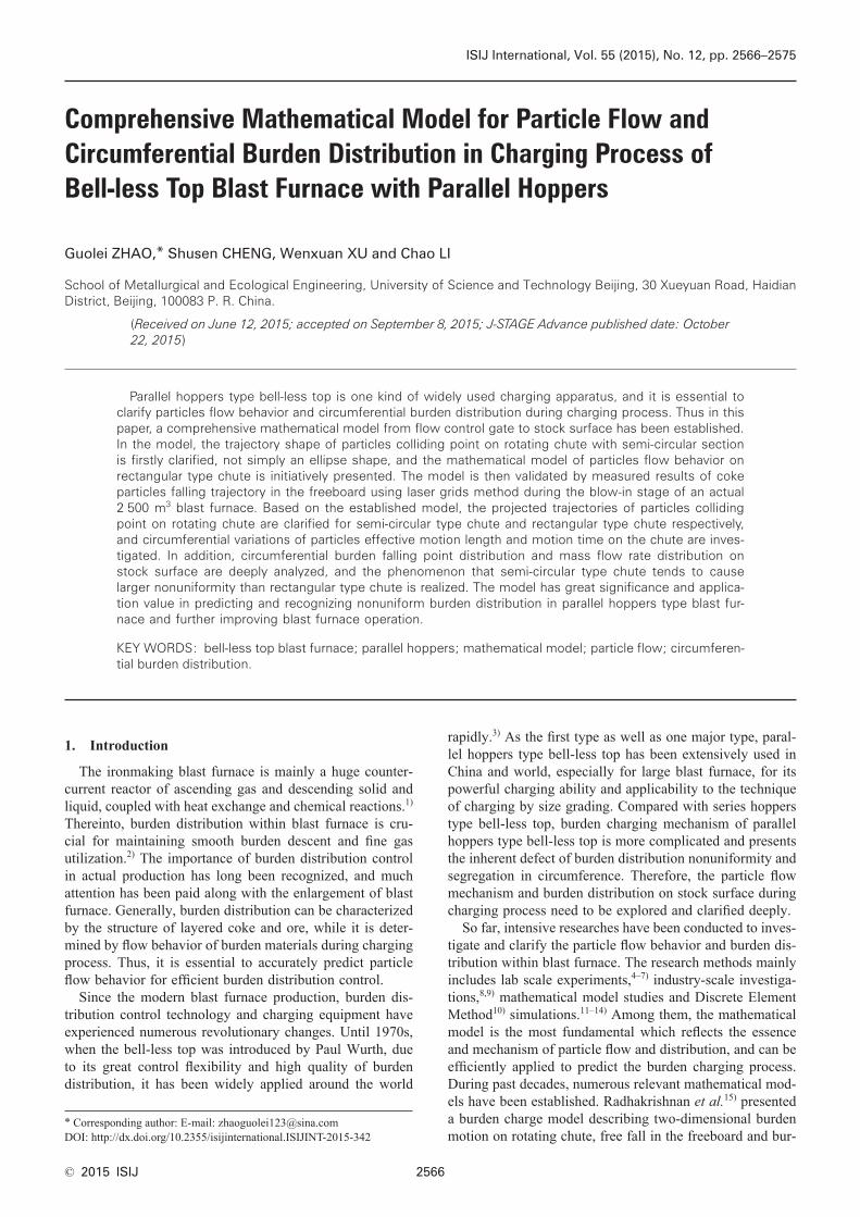
After burden particles collide on rotating chute, they will flow down along the chute, and rotating chute acts as a significant means in controlling burden distribution through altering particles flow behavior on the chute. Due to the variation of particles colliding point on the chute in circum-ference, particles motion time on the chute changes periodi-cally, as shown in Fig. 9. Particles motion time on the chute mainly depends on the effective motion length, thus its cir-
Fig. 8. Circumferential variation of effective particles motion length in longitudinal direction on the chute.
Fig. 9. Circumferential variation of particles motion time on rotating chute with (a) semi-circular section and (b) rect-angular section at different chute tilting angles.
Fig. 7. The projected trajectory of particles colliding point on rotating chute with (a) semi-circular section and (b) rect-angular section at different chute tilting angles.
ISIJ International, Vol. 55 (2015), No. 12
© 2015 ISIJ2573
cumferential variation trend is similar with that of effective motion length. On the other hand, particles motion time is also affected by initial particle position and velocity, lead-ing to asymmetry with the line of β=180° in circumference. And for semi-circular type chute, the maximum motion time usually appears as chute azimuth angle is higher than 180°, while the maximum motion time on rectangular type chute appears as chute azimuth angle is lower than 180°. As for the former, the initial positive tangential velocity contributes to the increase of particles motion time although effective motion length decreases when chute azimuth angle exceeds 180°, while for the latter, as chute azimuth angle gets close to 180°, the relative small value of initial longitudinal veloc-ity becomes dominant than the increase of effective motion length to reach the maximum motion time. Moreover, as chute tilting angle increases, particles will move with longer time on the chute, but the difference between maximum time and minimum time reduces since the shrinkage of col-liding point trajectory.
3.3. Analysis of Circumferential Burden DistributionDue to the periodically variation of burden particles flow
behavior during charging process as chute rotates circum-ferentially, it will inevitably give rise to nonuniform burden distribution on stock surface in circumference, not only for particles falling point distribution but also for mass flow rate distribution. And quantitatively analyses on nonuniform burden distribution contribute to thorough understanding of influence mechanism of burden charging pattern on blast furnace internal phenomenon, as well as guidance on improving burden distribution.
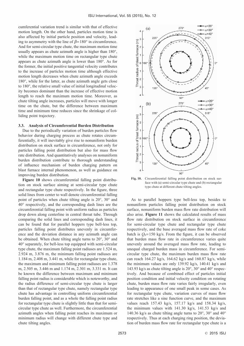
Figure 10 shows circumferential falling point distribu-tion on stock surface aiming at semi-circular type chute and rectangular type chute respectively. In the figure, three solid lines from center to wall denote circumferential falling point of particles when chute tilting angle is 20°, 30° and 40° respectively, and the corresponding dash lines are the circumferential falling point with uniform radius as particles drop down along centerline in central throat tube. Through comparing the solid lines and corresponding dash lines, it can be found that for parallel hoppers type bell-less top, particles falling point distributes unevenly in circumfer-ence and the deviation distance in any azimuth angle can be obtained. When chute tilting angle turns to 20°, 30° and 40° separately, for bell-less top equipped with semi-circular type chute, the maximum falling point radiuses are 1.524 m, 2.924 m, 3.876 m, the minimum falling point radiuses are 1.184 m, 2.408 m, 3.441 m, while for rectangular type chute, the maximum and minimum falling point radiuses are 1.378 m, 2.505 m, 3.446 m and 1.174 m, 2.301 m, 3.331 m. It can be known the difference between maximum and minimum falling point radius is considerable which is noteworthy, and the radius difference of semi-circular type chute is larger than that of rectangular type chute, namely rectangular type chute has advantage in controlling uniform circumferential burden falling point, and as a whole the falling point radius for rectangular type chute is slightly little than that for semi-circular type chute as well. Furthermore, the circumferential azimuth angles when falling point reaches its maximum or minimum radius will change with different chute type and chute tilting angles.
As to parallel hoppers type bell-less top, besides to nonuniform particles falling point distribution on stock surface, nonuniform burden mass flow rate distribution will also arise. Figure 11 shows the calculated results of mass flow rate distribution on stock surface in circumference for semi-circular type chute and rectangular type chute respectively, and the base averaged mass flow rate of coke batch is Q0=150 kg/s. From the figure, it can be observed that burden mass flow rate in circumference varies quite unevenly around the averaged mass flow rate, leading to unequal charged burden mass in circumference. For semi-circular type chute, the maximum burden mass flow rate can reach 164.27 kg/s, 164.62 kg/s and 160.87 kg/s, while the minimum values are only 139.92 kg/s, 140.41 kg/s and 143.93 kg/s as chute tilting angle is 20°, 30° and 40° respec-tively. And because of combined effect of particles initial position condition and initial velocity condition on rotating chute, burden mass flow rate varies fairly irregularly, even leading to appearance of one small peak in some cases. As for rectangular type chute, variation curves of mass flow rate stretches like a sine function curve, and the maximum values reach 157.43 kg/s, 157.17 kg/s and 158.34 kg/s, the minimum values with 141.30 kg/s, 141.53 kg/s and 140.36 kg/s as chute tilting angle turns to 20°, 30° and 40° respectively. Thus at each charging ring position, the devia-tion of burden mass flow rate for rectangular type chute is a
Fig. 10. Circumferential falling point distribution on stock sur-face with (a) semi-circular type chute and (b) rectangular type chute at different chute tilting angles.

ISIJ International, Vol. 55 (2015), No. 12
© 2015 ISIJ 2574
little smaller than that for semi-circular type chute. On the other hand, the regularity of burden mass flow rate variation for rectangular type chute is stronger than that for semi-circular type chute with different charging angles.
Based on Eq. (25), the overall deviation of mass flow rate in circumference can be calculated to evaluate nonuniform degree of burden mass flow rate distribution. As chute tilt-ing angle turns to 20°, 30° and 40° respectively, the overall deviations are 6.82 kg/s, 7.58 kg/s, 6.58 kg/s for semi-circular type chute, and 5.55 kg/s, 5.36 kg/s, 6.26 kg/s for rectangular type chute. It indicates that nonuniform degree of burden mass flow rate distribution by using semi-circular type chute is a little more serious than that by using rectan-gular type chute. And the nonuniform phenomena should be paid attention in actual production, and proper countermea-sures should be explored to ease the influence of nonuniform burden distribution on blast furnace operation and improve relevant economic indicators.
4. Conclusions
Aiming at the charging process of bell-less top blast furnace equipped with parallel hoppers, a comprehensive mathematical model describing particles flow behaviors and burden distribution is established, including particles flow behavior from flow control gate to rotating chute, particles flow behavior on rotating chute, particles flow behavior in the freeboard and circumferential falling point and mass flow rate distribution on stock surface. Within the model, particles colliding point trajectory on rotating chute with semi-circular section is firstly presented to be a non-ellipse shape, and the projected shape on the chute is formulated. Furthermore, the mathematical model of particles flow behavior on rectangular type chute which is also widely
applied has been initiatively developed.In order to verify applicability of the model, measured
results of coke particles falling trajectory in the freeboard conducted by using laser grids method during the blow-in stage of an actual 2 500 m3 bell-less top blast furnace is used to compare with the calculated results by the model, and the agreement is acceptable. Based on the established model, particles flow behaviors during charging process have been analyzed, the projected trajectories of particles colliding point on rotating chute are clarified for semi-circular type chute and rectangular type chute respectively. As chute rotates circumferentially, particles effective motion length and motion time on the chute vary periodically, and the maximum and minimum effective motion lengths are at the chute azimuth angle of 180°and 0° respectively. And with the increase of chute tilting angle, both particles effective motion length and motion time will increase. In addition, circumferential burden falling point distribution and mass flow rate distribution on stock surface are deeply studied for semi-circular type chute and rectangular type chute respectively. When chute tilting angle turns to 20°, 30° and 40° respectively, the overall deviations of burden mass flow rate are 6.82 kg/s, 7.58 kg/s, 6.58 kg/s for semi-circular type chute, and 5.55 kg/s, 5.36 kg/s, 6.26 kg/s for rectangular type chute, indicating the former with larger nonuniformity. And nonuniform burden distribution should arouse operator’s attention to realize efficient production of blast furnace.
AcknowledgementThe authors would like to appreciate the financial support
from the National Natural Science Foundation of China (No. 61333002).
Nomenclature CD: drag coefficient (− ) dp: particle equivalent diameter (m) D0: diameter of central throat tube (m) e: tilting distance of rotating chute (m) Fb: buoyancy force (N) Fc: centrifugal force (N) Fd: drag force (N) Ff: friction force (N) FN: reaction force (N) Fr: coriolis force (N) g: gravitational acceleration (m/s2) h0: operational stock level (m) ha: effective height from flow control gate to hook
point of rotating chute (m) hb: effective height from hook point of rotating chute
to colliding point of particles on chute (m) H: distance from hook point of rotating chute to zero
stock level (m) i: portion number of discretized circumference,
i=1, 2, …, N K: correction factor of particles collision (− ), con-
sidering velocity dissipation among particles and wall collision, the value gets 0.5 in the text.
L0: length of rotating chute (m) L: effective longitudinal motion length of particle on
rotating chute (m)
Fig. 11. Circumferential mass flow rate distribution on stock sur-face with (a) semi-circular type chute and (b) rectangular type chute at different chute tilting angles.

ISIJ International, Vol. 55 (2015), No. 12
© 2015 ISIJ2575
m: mass of particle (kg) M: burden batch weight (kg) n: rounds number of burden distribution (− ) N: number of discretized portions in circumferential
direction Q: mass flow rate (kg/s) r: distance vector (m) rc: radius of burden flow centroid from BF center
line in central throat tube (m) rn: radius of particle falling point on stock surface
(m) R: radius of cross-section for rotating chute with
semi-circular section (m) Re: Reynolds number (− ) t: time (s) T: total motion time of particle from flow control
gate to stock surface (s) v: velocity (m/s) v0: initial velocity of burden particle at the flow con-
trol gate (m/s) v1: particle velocity as particle reaches chute surface
(m/s) W: width of cross-section for rotating chute with
rectangular section (m) x, y, z: axes of the Pxyz coordinate system (m) x′, y′, z′: axes of the Qx’y’z’ coordinate system (m) X, Y, Z: axes of the OXYZ coordinate system (m)
Greek letters α: tilting angle of rotating chute (°) β: circumferential angle or azimuth angle of rotating
chute when particles just collide on chute (°) βc: azimuth angle of rotating chute when particles
just locate the chute end (°) βSL: azimuth angle of particles when particles just
reach stock level (°) θ: deflection angle of particle in rotating chute (°) ω: chute rotating angular velocity (rad/s) ϕ: shape factor of burden particle (− ) ρ: density (kg/m3) λ: material flow coefficient (− ), for metallurgical
burden material, the value ranges from 0.3 to 0.4. In the text, the value for coke material takes 0.4, while for ore material it takes 0.3.
μ: friction coefficient (− ) μg: gas viscosity (Pa·s)
Subscripts f: freeboard g: gas p: particle t: central throat tube
REFERENCES
1) Y. Omori: Blast Furnace Phenomena and Modelling, Elsevier, London, (1987), 297.
2) M. Naito, K. Takeda and Y. Matsui: ISIJ Int., 55 (2015), 7.3) A. Ghosh and A. Chatterjee: Ironmaking and Steelmaking: Theory
and Practice, PHI Learning Private Limited, New Delhi, (2008), 35.4) Y. Kajiwara, T. Jimbo, T. Joko, Y. Aminaga and T. Inada: Trans.
Iron Steel Inst. Jpn., 24 (1984), 799.5) J. Jimenez, J. Mochon, A. Formoso and J. S. Ayala: ISIJ Int., 40
(2000), 114.6) Y. Matsui, A. Kasai, K. Ito, T. Matsuo, S. Kitayama and N. Nagai:
ISIJ Int., 43 (2003), 1159.7) Y. W. Yu and H. Saxen: Ironmaking Steelmaking, 38 (2011), 432.8) S. Nag, M. Guha, S. Kundu, S. K. Sinha and U. Singh: ISIJ Int., 48
(2008), 1316.9) P. Y. Du, S. S. Cheng and Z. J. Teng: China Metall., 21 (2011), 1.
10) P. A. Cundall and O. D. L. Strack: Geotechnique, 29 (1979), 47.11) Y. W. Yu and H. Saxen: Steel Res. Int., 84 (2013), 1018.12) Y. W. Yu and H. Saxen: Ind. Eng. Chem. Res., 51 (2012), 7383.13) H. Mio, M. Kadowaki, S. Matsuzaki and K. Kunitomo: Miner. Eng.,
33 (2012), 27.14) H. Mio, S. Komatsuki, M. Akashi, A. Shimosaka, Y. Shirakawa, J.
Hidaka, M. Kadowaki, S. Matsuzaki and K. Kunitomo: ISIJ Int., 49 (2009), 479.
15) V. R. Radhakrishnan and K. M. Ram: J. Process Contr., 11 (2001), 565.
16) J. I. Park, H. J. Jung, M. K. Jo, H. S. Oh and J. W. Han: Met. Mater. Int., 17 (2011), 485.
17) B. Krcek, V. Bocka, L. Broz and J. Mrazck: Hutnicke Listy, 32 (1977), 466.
18) S. Nag and V. M. Koranne: Ironmaking Steelmaking, 36 (2009), 371.19) Z. J. Teng, S. S. Cheng, P. Y. Du and X. B. Guo: Int. J. Min. Met.
Mater., 20 (2013), 620.20) T. Z. Ren, J. Xin, H. Y. Ben and C. Z. Yu: J. Iron Steel Res. Int., 13
(2006), 14.21) J. Xu, S. L. Wu, M. Y. Kou, L. H. Zhang and X. B. Yu: Appl. Math.
Model., 35 (2011), 1439.22) H. T. Zhao, M. H. Zhu, P. Du, S. Taguchi and H. C. Wei: ISIJ Int.,
52 (2012), 2177.23) A. Haider and O. Levenspiel: Powder Technol., 58 (1989), 63.