composites testing and model identification 2006composites testing and model identification 10, 11...
TRANSCRIPT

Composites Testing and Model Identification
2006
Book of Abstracts
10th-12th April, 2006 Faculdade de Engenharia da Universidade do Porto
Sponsored by:


i
ACKNOWLEDGEMENTS
We wish to thank the following for their contribution to the success of this conference:
European Office of Aerospace Research and Development, Air Force Office of Scientific Research, United States Air Force Research Laboratory <http://www.london.af.mil>. Fundação Calouste Gulbenkian. Luso-American Foundation. Fundação para a Ciência e a Tecnologia, Ministério da Ciência, Tecnologia e Ensino Superior. Airbus. Instituto de Engenharia Mecânica e Gestão Industrial – INEGI. Association Française de Mécanique – AFM. American Society for Composites – ASC. Institute of Materials, Minerals and Mining – IOM3. Association pour les Matériaux Composites – AMAC. Asociación Española de Materiales Compuestos – AEMAC.

iii
TABLE OF CONTENTS
ACKNOWLEDGEMENTS ........................................................................................................ i
TABLE OF CONTENTS..........................................................................................................iii
SESSION PROGRAMME......................................................................................................... v
FULL PROGRAMME .............................................................................................................vii
SESSION 1 – NOVEL METHODS AND RESIDUAL STRESSES I ...................................... 1
POSTER SESSION 1............................................................................................................... 11
SESSION 2 – FRACTURE I ................................................................................................... 29
SESSION 3 – STRUCTURES ................................................................................................. 39
POSTER SESSION 2............................................................................................................... 45
SESSION 4 – FABRIC COMPOSITES .................................................................................. 63
SESSION 5 – FATIGUE AND DURABILITY ...................................................................... 73
POSTER SESSION 3............................................................................................................... 81
SESSION 6 – DAMAGE MODELS I ..................................................................................... 97
SESSION 7 – FULL FIELD TECHNIQUES ........................................................................ 105
POSTER SESSION 4............................................................................................................. 115
SESSION 8 – TESTING........................................................................................................ 129
SESSION 9 – SCALE EFFECTS AND JOINTS .................................................................. 137
POSTER SESSION 5............................................................................................................. 145
SESSION 10 – NOVEL METHODS AND RESIDUAL STRESSES II............................... 161
SESSION 11 – FRACTURE II .............................................................................................. 171
SESSION 12 – DAMAGE MODELS II ................................................................................ 181
AUTHOR INDEX.................................................................................................................. 189


v
3RD INTERNATIONAL CONFERENCE ON COMPOSITES TESTING AND MODEL IDENTIFICATION
10, 11 and 12 April 2006
Faculdade de Engenharia da Universidade do Porto, Portugal
SESSION PROGRAMME
MONDAY, 10TH APRIL 08.00 – 08.30 Registration
08.30 – 08.45 Conference Opening and Welcome to Porto
08.45 – 10.25 Session 1 – NOVEL METHODS AND RESIDUAL STRESSES I Chair: Prof. Fabrice Pierron, ENSAM Chalons, France
10.25 – 11.10 Coffee Break + Poster Session 1
11.10 – 12.50 Session 2 – FRACTURE I Chair: Prof. Ivana Partridge, Cranfield University, United Kingdom
12.50 – 14.00 LUNCH
14.00 – 15.40 Session 3 – STRUCTURES Chair: Dr. Carlos G. Dávila, NASA Langley Research Center, USA
15.40 – 16.25 Coffee Break + Poster Session 2
16.25 – 18.05 Session 4 – FABRIC COMPOSITES Chair: Prof. Stepan V. Lomov, Katholieke Universiteit Leuven, Belgium
18.30 Reception at Círculo Universitário

vi
TUESDAY, 11TH APRIL 08.30 – 10.35 Session 5 – FATIGUE AND DURABILITY
Chair: Prof. Manuel de Freitas, Technical University of Lisbon, Portugal
10.35 – 11.15 Coffee Break + Poster Session 3
11.15 – 12.55 Session 6 – DAMAGE MODELS I Chair: Dr. Christophe Cluzel, Laboratoire de Mécanique et Technologie, France
12.55 – 14.00 LUNCH
14.00 – 15.40 Session 7 – FULL FIELD TECHNIQUES Chair: Dr. William Broughton, National Physics Laboratory, United Kingdom
15.40 – 16.20 Coffee Break + Poster Session 4
16.20 – 18.00 Session 8 – TESTING Chair: Prof. Josep Costa, University of Girona, Spain
18.30 Conference Dinner at the Cellars of Port Wine in Vila Nova de Gaia
WEDNESDAY, 12TH APRIL 08.30 – 10.35 Session 9 – SCALE EFFECTS AND JOINTS
Chair: Prof. Michael Wisnom, University of Bristol, United Kingdom
10.35 – 11.15 Coffee Break + Poster Session 5
11.15 – 12.55 Session 10 – NOVEL METHODS AND RESIDUAL STRESSES II Chair: Prof. John Botsis, Swiss Federal Institute of Technology, Switzerland
12.55 – 14.00 LUNCH
14.00 – 15.40 Session 11 – FRACTURE II Chair: Prof. Janis Varna, Lulea University of Technology, Sweden
15.40 – 16.00 Coffee Break
16.00 – 17.15 Session 12 – DAMAGE MODELS II Chair: Dr. Silvestre T. Pinho, Imperial College, United Kingdom
17.15 Conference Closes

vii
3RD INTERNATIONAL CONFERENCE ON COMPOSITES TESTING AND MODEL IDENTIFICATION
10, 11 and 12 April 2006
Faculdade de Engenharia da Universidade do Porto, Portugal
FULL PROGRAMME
MONDAY, 10TH APRIL 08.00 – 08.30 Registration
08.30 – 08.45 Conference Opening and Welcome to Porto
SESSION 1 NOVEL METHODS AND RESIDUAL STRESSES I Chair: Prof. Fabrice Pierron, ENSAM Chalons, France
08.45 – 09.10 Aleksandar Sekulic, A. Curnier, École polytechnique fédérale de Lausanne (EPFL), Switzerland An epoxy-stamp on glass-disc specimen exhibiting stable debonding for identifying adhesive properties
09.10 – 09.35 Abul Rahim A. Arafath, Reza Vaziri, Anoush Poursartip, The University of British Columbia, Canada A hierarchical finite element approach to modelling process-induced deformations in composite structures
09.35 – 10.00 Simon Jones, Kevin Potter, Michael Wisnom, University of Bristol, UK Measurements of frictional processes in the processing of advanced composites and their importance in modelling cure and residual stresses / distortions
10.00 – 10.25 Gabriel Dunkel, Laurent Humbert, John Botsis, École polytechnique fédérale de Lausanne (EPFL), Switzerland Identification of interfacial properties using FBG sensors in a fibre pull-out test

viii
10.25 – 11.10 COFFEE BREAK + POSTER SESSION 1
Joan A. Mayugo, Pere Maimí, Pedro P. Camanho, Carlos G. Dávila, Universitat de Girona, Spain/ Universidade do Porto, Portugal/ NASA Langley Research Center, USA A micromechanics-based periodic damage model for laminated composites Jin-Hwan Kim, Fabrice Pierron, Kashif Syed-Muhamad, Michael R. Wisnom, Michel Grédiac, Evelyne Toussaint, ENSAM and IFMA, France/ University of Bristol, UK Identification of the local stiffness reduction of a damaged composite plate using the virtual fields method Daniel Trias, Joan A. Mayugo, Albert Turon, Norbert Blanco, Josep Costa, Universitat de Girona, Spain Simulation of the effects of residual stresses on matrix cracking probability of unidirectional lamina of carbon reinforced epoxies Carla McGregor, Reza Vaziri, Anoush Poursartip, The University of British Columbia, Canada Simulation of progressive damage development in braided composite tubes undergoing axial crushing Hugo Faria, Marcelo F. S. F. de Moura, Rui M. Guedes, Instituto de Engenharia Mecânica e Gestão Industrial and Universidade do Porto, Portugal 2D numerical simulation of GRP pipes’ failure under ring load condition Fangming Zhao, Frank Jones, The University of Sheffield, UK Identifying the effect of shear residual stresses on stress transfer in single short fibre composites using photoelasticity Giangiacomo Minak, Andrea Zucchelli, Facoltà di Ingegneria Università degli Studi di Bologna, Italy Residual strength of laminated graphite-epoxy composite circular plates damaged by transversal load Alain Prenleloup, Thomas Gmür, Philippe Bonhôte, John Botsis, École polytechnique fédérale de Lausanne (EPFL), Switzerland Experimental and numerical strength analysis of mixed metal-composite crimped or adhesively bonded joints Danilo Bardaro, Orazio Manni, Paolo Corvaglia, Rossella Modarelli, Teresa Primo, CETMA Consortium, Italy Experimental study and numerical modelling of solid and hollow FRP-confined concrete members

ix
SESSION 2 FRACTURE I
Chair: Prof. Ivana Partridge, Cranfield University, United Kingdom
11.10 – 11.35 Stefanie Feih, R. Sweeting, Z. Mathys, A.G. Gibson, A.P. Mouritz, Royal Melbourne Institute of Technology, CRC-ACS and Platform Sciences Laboratory, Australia/ University of Newcastle-upon-Tyne, UK Failure of load-carrying polymer composites in fire
11.35 – 12.00 Silvestre T. Pinho, Paul Robinson, Lorenzo Iannucci, Imperial College, UK Measuring the fracture toughness for different failure modes in laminated composites
12.00 – 12.25 Josep Costa, Jordi Renart, E. González, Albert Turon, S. Lazcano, Universitat de Girona and AIRBUS España, Spain Influence of the geometry of the specimen on the occurrence of delamination during adhesive joint testing
12.25 – 12.50 Rosa Marat-Mendes, Manuel de Freitas, Escola Superior de Tecnologia de Setúbal and Instituto Superior Técnico, Portugal Experimental and numerical studies of mode I, II, III and mixed-mode I-II energy release rate in laminates
12.50 – 14.00 LUNCH
SESSION 3 STRUCTURES Chair: Dr. Carlos G. Dávila, NASA Langley Research Center, USA
14.00 – 14.50 INVITED LECTURE 1 Didier Batiste, ENSAM École nationale supérieure d'arts et métiers, France Multiscale analysis of the strain rate effect on the behaviour and damage of composite materials
14.50 – 15.15 Jérôme Molimard, Alain Vautrin, Jean-Marc Béraud, P. Henrat, École Nationale Supérieure des Mines de Saint-Étienne and Hexcel Reinforcements, France Contribution to composite ‘T’ beam design in industrial environment by using the grid technique
15.15 – 15.40 Nicolas Baral, P. Davies, D. Cartié, C. Baley, Trimaran GROUPAMA, IFREMER and Université de Bretagne Sud, France/ Cranfield University, UK Optimization of composite materials and structures for racing multi-hull yachts
15.40 – 16.25 COFFEE BREAK + POSTER SESSION 2
Kim Branner, Risø National Laboratory, Denmark Static testing of cross-section of wind turbine blade

x
Daniel P. N. Vlasveld, Stephen J. Picken, Harald E. N. Bersee, Delft University of Technology, Netherlands Continuous fibre composites with a nanocomposite matrix Christian Lundsgaard-Larsen, Rasmus C. Østergaard, Bent F. Sørensen, Christian Berggreen, Technical University of Denmark and Risø National Laboratory, Denmark Fracture toughness of skin/core interfaces in sandwich materials under mixed mode loadings Norbert Blanco, Josep Costa, E. Kristofer Gamstedt, Leif E. Asp, University of Girona, Spain/ Royal Institute of Technology and SICOMP AB, Sweden Experimental analysis of the variable mixed-mode fatigue delamination in a carbon fibre-epoxy laminate Robin Olsson, Imperial College, UK Initial study of impact damage stiffness by full field optical method Leonardo Pagnotta, Giambattista Stigliano, University of Calabria, Italy Elastic characterization of anisotropic plates by genetic algorithms and interferometric techniques Francisco J. Bernardo, Abílio M. Jesus, José J. Morais, Victor M. Filipe, João M. Barroso, Universidade de Trás-os-Montes e Alto Douro, Portugal Identification of foundation modulus of bolted timber joints using full-field displacement measurements Filipe Teixeira-Dias, Joaquim P. Cruz, António A. Campos, João A. Oliveira, Universidade de Aveiro, Portugal Variable-step feedback damping optimisation of the viscoplastic constitutive modelling of metal matrix composites SESSION 4 FABRIC COMPOSITES
Chair: Prof. Stepan V. Lomov, Katholieke Universiteit Leuven, Belgium
16.25 – 16.50 Roberts Joffe, David Mattsson, Luleå University of Technology, Sweden Methodology for characterization of internal structure of NCF composite and its influence on mechanical properties
16.50 – 17.15 Fredrik Edgren, Leif E. Asp, SICOMP AB, Sweden Determination of strength parameters for NCF composites
17.15 – 17.40 Giuseppe Dell’Anno, Denis D Cartié, Giuliano Allegri, Ivana K Partridge, Amir Rezai, Cranfield University and BAE Systems, Advanced Technology Centre, UK Exploring mechanical property balance in tufted carbon fabric/epoxy composites
17.40 – 18.05 Yuichiro Aoki, Yosuke Nagao, Takashi Ishikawa, Fumihito Takeda, Japan Aerospace Exploration Agency and Mitsubishi Heavy Industries, LTD, Japan Experimental evaluation and consideration of numerical method of zanchor CFRP laminates
18.30 Reception at Círculo Universitário

xi
TUESDAY, 11TH APRIL SESSION 5 FATIGUE AND DURABILITY
Chair: Prof. Manuel de Freitas, Technical University of Lisbon, Portugal
08.30 – 09.20 INVITED LECTURE 2 Paul Robinson, Department of Aeronautics, Imperial College London, UK Delamination Research: Progress in the last two decades and the challenges ahead
09.20 – 09.45 Gregory A. Schoeppner, Kishore V. Pochiraju, G. P. Tandon, Air Force Research Laboratory, Steven’s Institute of Technology and University of Dayton Research Institute, USA Long-term aging and durability of high temperature polymer composites
09.45 – 10.10 Masamichi Kawai, M. Koizumi, University of Tsukuba, Japan Nonlinear constant fatigue life diagrams for CFRP laminates
10.10 – 10.35 Elena Correa, E. K. Gamstedt, F. París, Universidad de Sevilla, Spain/ KTH Solid Mechanics, Sweden Fibre-matrix debonding in transverse cyclic loading of unidirectional composite plies
10.35 – 11.15 COFFEE BREAK + POSTER SESSION 3
Rim Zouari, Abedelwahed Ben Hamida, Hélène Dumontet, Université Pierre et Marie Curie, France A micromechanical modelling for prediction of behaviour and damage of polydisperse syntactic foams Janice M. Dulieu-Barton, T. R. Emery, P.R. Cunningham, University of Southampton, UK Assessing fatigue damage in GRP components using infrared techniques José T. San-José, Pere Roca, Pilar Prendes, Juan M. Mieres, Fundación LABEIN, Universidad Politécnica de Cataluña, GAIRESA and NECSO, Spain Evaluation of the anchorage behaviour of the FRP wet lay-up laminates applied to concrete substrates Cláudio S. Lopes, Pedro P. Camanho, Zafer Gürdal, Universidade do Porto, Portugal and Delft University of Technology Failure Analysis of Tow-Placed, Variable-Stiffness Composite Panels Rui António S. Moreira, J. Dias Rodrigues, Universidade de Aveiro and Universidade do Porto, Portugal A plate finite element with through-thickness stiffness for sandwich structures modelling Maria Antonietta Aiello, Paolo Corvaglia, Adolfo Fortunato, Orazio Manni, Federica Pedone, University of Lecce, Consorzio CETMA and Politecnico di Milano, Italy Testing and modelling of the bond behaviour between CFRP sheet and curved masonry substrate
xii
Josep Vicens, Norbert Blanco, Benigne Corbella, Josep Costa, I. Baraibar, F. Cabrerizo, J.M. Pintado, A. Fernández-Canteli, J. Viña, A. Argüelles, Universitat de Girona, Instituto Nacional de Técnica Aeroespacial and Universidad de Oviedo, Spain New mechanical fixtures for load introuction in DCB tests: design and performance Joaquim P. Cruz, J.A. Oliveira, António A. Campos, Filipe Teixeira-Dias, Universidade de Aveiro, Portugal Two-scale modelling of the thermomechanical behaviour of metal matrix composites SESSION 6 DAMAGE MODELS I
Chair: Dr. Christophe Cluzel, Laboratoire de Mécanique et Technologie, France
11.15 – 11.40 Janis Varna, Johannes Eitzenberger, Modris Megnis, Luleå University of Technology, Sweden/ OSTBY AB, Latvia Damage evolution in composite laminates with matrix cracks and fiber breaks
11.40 – 12.05 Amir Tabaković, Ciaran McNally, L. G. Sorelli, Amanda Gibney, Michael D. Gilchrist, University College Dublin, Ireland Development of a combined micromechanics & damage mechanics model for the design of asphalt pavements
12.05 – 12.30 Ireneusz Lapczyk, Abaqus, Inc., USA Progressive damage modeling in fiber-reinforced materials
12.30 – 12.55 Jens Wiegand, Ben Elliott, Nik Petrinic, University of Oxford, UK Physically based failure criteria for prediction of damage evolution in composite materials subjected to impact loading
12.55 – 14.00 LUNCH
SESSION 7 FULL FIELD TECHNIQUES Chair: Dr. William Broughton, National Physics Laboratory, United Kingdom
14.00 – 14.25 Fangming Zhao, Frank Jones, The University of Sheffield, UK Photoelastic characterisation of the stress transfer at fibre-break in model composites
14.25 – 14.50 Michel R. C. Fouinneteau, Anthony K. Pickett, Ralf Lichtenberger, Cranfield University, UK/ LIMESS Messtechnik & Software GmbH, Germany Identification of elastic and damage parameters using digital image correlation technique for braid reinforced composites
14.50 – 15.15 Marie-Pierre Moutrille, Katell Derrien, Didier Baptiste, Michel Grédiac, Xavier Balandraud, LIM - UMR CNRS and French Institute for Advanced Mechanics, France Trough-thickness strain field measurement in a composite/aluminium adhesive joint

xiii
15.15 – 15.40 Fabrice Pierron, Ben Green, Michael R. Wisnom, ENSAM – LMPF, France/ Bristol University, UK Optical full-field assessment of the damage progression in a composite open-hole tension test
15.40 – 16.20 COFFEE BREAK + POSTER SESSION 4
Yutaka Iwahori, Takashi Ishikawa, Naoyuki Watanabe, Japan Aerospace Exploration Agency and Tokyo Metropolitan University, Japan Experimental evaluation of interlaminar strength properties under out-of-plane load for Kevlar® stitched CFRP laminates António A. Campos, Joaquim P. Cruz, João A. Oliveira, Filipe Teixeira-Dias, Universidade de Aveiro, Portugal The effect of fibre reinforcement on the thermally induced residual stress fields of metal matrix composites Yves Perrot, Peter Davies, Christophe Baley, Grégoire Dolto, Université de Bretagne Sud, IFREMER and Fédération des Industries Nautiques, France Characterization of mechanical properties of glass/polyester composites for boat construction Silvio Pappadà, Rocco Rametta, Maria Antonietta Aiello, Alfonso Maffezzoli, Consorzio CETMA and University of Lecce, Italy Study of a composite-to-metal tubular joint Corine Florens, Etienne Balmès, Franck Cléro, Ecole Centrale Paris and DDSS/CAV, France Estimation of honeycomb sandwich properties through numerical homogenization Hugo Faria, Rui M. Guedes, António T. Marques, Instituto de Engenharia Mecânica e Gestão Industrial and Universidade do Porto, Portugal Durability of GFRP pipes under ring-deflection conditions M. Cristina S. Ribeiro, Paulo J. R. O. Nóvoa, António T. Marques, António J. M. Ferreira, Instituto de Engenharia Mecânica e Gestão Industrial and Universidade do Porto, Portugal Mechanical behaviour of lightweight wood fibre-modified polymer concrete Zouaoui Sereir, EA. Adda-Bedia, Université des Sciences et de la Technologie d’Oran and Université de Sidi Bel Abbès, Algeria Effects of stacking sequences and temperature variation on the transverse stresses in the laminated composite

xiv
SESSION 8 TESTING
Chair: Prof. Josep Costa, University of Girona, Spain
16.20 – 16.45 Dmitry Ivanov, Stepan Lomov, Ignaas Verpoest, Alexander Zisman, Katholieke Universiteit Leuven, Belgium Noise reduction of strain mapping data and identification of damage initiation of carbon-epoxy triaxial braided composite
16.45 – 17.10 Jean-Denis Mathias, Xavier Balandraud, Michel Grédiac, French Institute for Advanced Mechanics and Blaise Pascal University, France Experimental study of composite patches subjected to a thermal loading
17.10 – 17.35 Daniel Hartung, M. Kintscher, L. Kärger, A. Wetzel, DLR Institute of Composite Structures and Adaptive Systems, Germany Stiffness and failure behaviour of folded sandwich cores under combined transverse shear and compression
17.35 – 18.00 Find Moelholt Jensen, Paul M. Weaver, Luca S. Cecchini, Henrik Stang, Risoe National Laboratory and Technical University of Denmark, Denmark/ University of Bristol, UK On aspects of non-linear bending behaviour of a wind-turbine blade under full-scale testing
18.30 Conference Dinner at the Cellars of Port Wine

xv
WEDNESDAY, 12TH APRIL SESSION 9 SCALE EFFECTS AND JOINTS
Chair: Prof. Michael Wisnom, University of Bristol, United Kingdom
08.30 – 09.20 INVITED LECTURE 3 David Mollenhauer, Air Force Research Laboratory, Dayton, OH, USA Interlaminar Deformation Along the Cylindrical Surface of a Hole in Laminated Composites
09.20 – 09.45 Lars Christian T. Overgaard, Pedro P. Camanho, Erik Lund, Aalborg University, Denmark/ Universidade do Porto, Portugal Structural response analyses of Vestas V52 wind turbine blade
09.45 – 10.10 Raymond Esnault, Serge Maison-Le Poec, EADS Corporate Research Centre, France Experimental identification of the behaviour of thick composites in biaxial and bearing tests
10.10 – 10.35 William Broughton, L. Crocker, M. Gower, R. Shaw, National Physical Laboratory, UK Validation of FEA predictions of bonded and bolted T-joints
10.35 – 11.15 COFFEE BREAK + POSTER SESSION 5
Nuno Dourado, S. Morel, M.F.S.F. de Moura, G. Valentin, J. Morais, Universidade de Trás-os-Montes e Alto Douro and Universidade do Porto/ LRBB, France Influence of the specimen size on the R-curve behaviour in wood Faustino Mujika, Neftalí Carbajal, Jesús María Romera, Ainhoa Arrese, Polytechnical University College, Spain Thermal stresses in unsymmetric cross-ply composite beams Arlindo Silva, João Lopes, Pedro Almeida, Luis Reis, Marco Leite, Instituto Superior Técnico, Instituto Politécnico de Setúbal and Instituto Politécnico de Tomar, Portugal Experimental testing of a natural cork-based composite – shear behaviour comparison with other materials for sandwich applications João A. Oliveira, Joaquim P. Cruz, António A. Campos, Filipe Teixeira-Dias, Universidade de Aveiro, Portugal Modelling the elastic behaviour of composite materials with asymptotic expansion homogenisation Feng H. Wang, Helmuth Toftegaard, Peter V Hendriksen, Bent F Sørensen, Northwestern Polytechnical University, Xi’an, P R China/ Riso National Laboratory, Denmark Tensile mechanical properties of bi-layer structure for solid oxide fuel cells Noureddine Boualem, Zouaoui Sereir, Université des sciences et de la technologie Mohamed Boudiaf d’Oran, Algeria Some applications on the cyclic evolution of the moisture concentration through a plate in hybrid composite

xvi
Mehdi Haghshenas, Reza Vaziri, Anoush Poursartip, The University of British Columbia, Canada Shear flow simulation of fibre-reinforced thermoset composites during the early stages of processing Kevin Potter, University of Bristol, UK Measurements of the snap-through behaviour and snap-through fatigue performance of bistable unsymmetric composite structures SESSION 10 NOVEL METHODS AND RESIDUAL STRESSES II
Chair: Prof. John Botsis, Swiss Federal Institute of Technology, Switzerland
11.15 – 11.40 Marco Matter, Thomas Gmür, Joël Cugnoni, Alain Schorderet, École polytechnique fédérale de Lausanne (EPFL), Switzerland Modal identification of the elastic properties in composite sandwich structures
11.40 – 12.05 Antonio Claret Palerosi, Sergio Frascino Muller de Almeida, Instituto Nacional de Pesquisas Espaciais and Instituto Tecnológico de Aeronáutica, Brasil Experimental and numerical analyses of non-symmetric composite laminates curvatures
12.05 – 12.30 Kevin Potter, Chris Setchell, Imetrum Ltd. Bristol. UK Point to point non-contact video extensometry for composite materials and structures – a comparison with full-field methods
12.30 – 12.55 Falk Hähnel, Klaus Wolf, Technische Universität Dresden, Germany Evaluation of the material properties of resin-impregnated NOMEX® paper as basis for the simulation of the impact behaviour of honeycomb sandwich
12.55 – 14.00 LUNCH

xvii
SESSION 11 FRACTURE II
Chair: Prof. Janis Varna, Lulea University of Technology, Sweden
14.00 – 14.25 Carlos G. Dávila, Albert Turon, Pedro P. Camanho, Universitat de Girona, Spain/ Universidade do Porto, Portugal/ NASA Langley Research Center, USA Decohesion elements for shell analysis
14.25 – 14.50 Larissa Sorensen, T. Gmür, J. Botsis, École polytechnique fédérale de Lausanne (EPFL), Switzerland Delamination propagation measurement in AS4/PPS using long gauge-length FBG sensors
14.50 – 15.15 Bent F. Sørensen, Torben K. Jacobsen, Risø National Laboratory and LM Glasfiber A/S, Denmark A j integral approach for the determination of mixed mode cohesive laws
15.15 – 15.40 Albert Turon, Josep Costa, Pedro P. Camanho, Carlos G. Dávila, Universitat de Girona, Spain/ Universidade do Porto, Portugal/ NASA Langley Research Center, USA Simulation of delamination under high cycle fatigue in composite materials
15.40 – 16.00 COFFEE BREAK
SESSION 12 DAMAGE MODELS II Chair: Dr. Silvestre T. Pinho, Imperial College, United Kingdom
16.00 – 16.25 David Vernet, Christophe Cluzel, Olivier Allix, LMT Cachan, France Modeling and identification of adhesive behaviour for marine composite application: a dedicated approach
16.25 – 16.50 Nathalie Pentecôte, Alastair F. Johnson, German Aerospace Center (DLR), Germany Determination of composites damage properties for impact modelling
16.50 – 17.15 George C. Papanicolaou, N.K. Anifantis, Th.V.Kosmidou, University of Patras, Greece Numerical and analytical investigation of interphasial stress and strain fields in particulates by means of the hybrid interphase concept
17.15 Conference Closes

1
SESSION 1 – NOVEL METHODS AND RESIDUAL STRESSES I
Chair: Prof. Fabrice Pierron ENSAM Chalons, France
Monday 10th April 08:45 – 10:25

2
AN EPOXY-STAMP ON GLASS-DISC SPECIMEN EXHIBITING STABLE DEBONDING FOR IDENTIFYING ADHESIVE PROPERTIES
A. Sekulic, A. Curnier Laboratoire de mécanique appliquée et d’analyse de fiabilité (LMAF)
École Polytechnique Fédérale de Lausanne (EPFL) CH-1015, Switzerland
ABSTRACT
In Contact Mechanics and Tribology, adhesion is the conservative reversible normal relation (contiguity) and attractive interaction (tension) at the interface between two materials in contact. ”Deadhesion” or rather decohesion, is the loss of adhesion. In Fracture Mechanics and Rheology, debonding is usually interpreted as a crack propagating along the material pair interface at the microscale and as damage at the macroscale.
This study is motivated by the fibre-matrix debonding which occurs in glass fibre reinforced epoxy matrix composites and decreases their strength. In this note, we focus our attention on the identification of the adhesive properties between glass and epoxy.
The basic adhesive property, entering a normal adhesion-decohesion law relating the normal tensile stress pn to the normal gap gn at an interface, is the surface energy of adhesion (per unit area) ω (of Dupré). It represents the local work dissipated during the decohesion process (i.e. at the particle pair or continuum elementary area microscale). In several contact mechanics models of adhesion-decohesion, the surface energy ω is equal to the product of two other basic adhesive properties, namely the adhesion peak stress πn and the decohesion rupture gap γn, or rather a fraction of it (e.g. one half),
12 n nω π γ= (1)
These adhesive properties are difficult to measure accurately because the decohesion process is often unstable.
In this article, we present an original axisymmetric specimen composed of an epoxy-stamp bonded on a glass-disc, which exhibits a stable decohesion under traction and hereby permits an accurate identification of the adhesive properties. Debonding stability is obtained by combining two stabilizing effects of the epoxy stamp geometry: axisymmetry and concavity, discovered by analogy with two observations in contact and fracture mechanics, respectively. In case of axisymmetry, the crack area grows with the square of its radius a2 (instead of its length a in a plane strain geometry). Concavity is inspired from the Tapered Double Cantilever Beam (TDCB) used in experimental FractureMechanics [Kinloch and Young (1983)] [1]. Optimization of the shape of the epoxy part was done by numerical simulations. To this end the Talon-Curnier contact-adhesion law [2] was used. According to that law, debonding is stable if the tension stress at the crack front decreases as the crack propagates, i.e. if the envelope of the tension stress at the crack front decreases along the radial axis. The simulations were carried out with the contact analysis program TACT. The final design of the axisymmetric concave epoxy-stamp on glass-disc specimen is shown in cross-section in Figure 1a and in perspective in Figure 1b.
a) Cross-section with tension envelope b) Perspective with cut sector
Figure 1- Axisymmetric concave epoxy-stamp on glass-disc specimen.

3
The graph of the tension stress envelope at crack front superposed on the mesh in Figure 1a shows that the debonding process is stable over a large radial zone.
The specimen is then pulled on a standard traction machine (Instron 5800). A controlled displacement w is imposed at the rate w = 1 mm/min. The traction force f, the specimen elongation u and the crack radius a were measured.
The experimental results are presented in Figure 2. The force histograph f = f(t) is shown in Figure 2a. The crack initiation (point A at radius r) and termination (point B at R) are easy to identify on this graph. It is clear that the debonding process is stable between A and B since an increasing force is necessary for advancing the crack from r to R. The early discontinuity (point C) corresponds to the (sudden) debonding of the mold release film interposed for initiating the crack.
a) Force-time curve b) Force-displacement curve
Figure 2- Force-time and force-displacement curve.
The adhesion properties (surface energy ω, peak stress πn and rupture gap γn) can be extracted from the experimental measurements [Fig. 2b] (specimen elongation u, traction force f and crack radius a) by the following procedure. The work dissipated between the initial crack radius r and the current one a is equal to the dissipation per unit area multiplied by the debonded area ( )2 2A a rπ= − :
( )2 212 n nA a rω π γ πΩ = = − (2)
Firstly, this dissipated energy Ω is measured on the experimental force-displacement graph f = f(u) [Fig. 2b]. It is equal to the area of the hysteresis loop obtained upon elastic unloading. Elastic unloading can be either idealised as linear or measured from a real experimental unloading. Secondly, the measured traction force f or prescribed specimen elongation u at the initial crack radius r is used as a boundary condition in a simulation of the stamp (free between 0 and r and fixed between r and R at its basis), with the contact analysis program TACT, in order to evaluate the adhesion peak stress πn.
Finally, the rupture gap γn is calculated by solving equation (2) for it
( )2 21
2 2nn na rωγπ ππ
Ω= =−
(3)
The stamp on disc specimen design can be used for other pairs of materials (provided one can be molded on the other). Finally, it can perhaps be adapted into a torsion experiment to study adherence and decoherence. Combining torsion with compression on a torsion-traction machine may permit to find out whether adherence depends on pressure or not.
REFERENCES
[1] Kinloch, A., Young, J.,”Fracture behaviour of Polymers”, Applied science Publishers, 1983.
[2] Talon, C., Curnier, A.,”A Model of Adhesion Coupled to Contact and Friction”, European Journal of Mechanics A/Solids, Vol. 22, 545-565, 2003.
4
A HIERARCHICAL FINITE ELEMENT APPROACH TO MODELING PROCESS-INDUCED DEFORMATIONS IN COMPOSITE STRUCTURES
Abul Rahim A Arafath, Reza Vaziri and Anoush Poursartip Composites Group
Departments of Civil Engineering & Materials Engineering The University of British Columbia
Vancouver, BC, Canada
ABSTRACT
Composite structures, unlike their metallic counterparts, are manufactured from the raw material in one step. As a result, because of the residual stresses that build up during the process, the precise shape and dimensions of the final part after tool removal are often difficult to control. In thin-walled composite structures, spring-back and warpage are commonly observed process-induced imperfections. Anisotropy in thermal and chemical strains causes a curved part to spring-in and the interactions between the tool and the part stemming from the inherent mismatch between their material properties leads to the residual warpage of the part [1].
During the processing of thermoset based composites, as the resin cures the effective elastic (and shear) modulus changes by as much as 6 orders of magnitude from roughly 1 KPa to 1 GPa. As the tool expands during the heat up phase, it stretches the part thus inducing a large gradient of stress through the thickness of the part due to the low shear modulus of the part. The stress gradient is locked in as the material cures. On removal of the tool, this stress causes the part to warp. It is very important to capture the stress gradient that occurs at the initial stage of cure to predict the part deformation accurately [2-3].
Shell elements are not able to capture such highly nonlinear through thickness stress gradients accurately as they incorporate a constant shear strain assumption. Hence a 3D solid element formulation is required. However, the main drawback of using solid elements is that a rather large number of elements are necessary to model the process-induced residual deformations. This is mainly due to the shear locking effect that occurs in solid elements when the element aspect ratio is very large. In recent years, many shell-like-solid element formulations have been reported in the literature, with to the intent of eliminating the locking effects. Dhondt [4] recently showed that 20-noded solid elements with reduced integration are effective in modelling thin-walled (shell like) structures. Even though this will allow us to use a large aspect ratio, one still needs more than one element (up to 8 elements) in the thickness direction to capture the large stress gradients during the initial stages of cure. Since this higher number of elements is necessary only at the initial stages, it is inefficient to use a constant number of elements in thickness direction throughout the curing process.
Hierarchical finite elements have been shown to be a very useful tool for refinement without changing the initial finite element mesh [5-6]. In recent years this method has been used to model shell like structures [7-8]. The main advantage of this method is that a node (or degrees of freedom) can be added to, or dropped in, an element without changing the shape functions corresponding to other nodes in the element. Hence this method is more suitable for dynamically changing the order of the element displacement interpolation.
In this work, the hierarchical element method is used to overcome the inefficiency of using a constant number of elements during the curing process. Our hierarchical element has 24-nodes (8 nodes at each of the top, bottom and middle surfaces) (Figure 1). The top and bottom surface nodes have the conventional translational degrees of freedom (u, v and w). The mid surface nodes have a variable number of unknowns. The displacement interpolation is given by:
1 1 2 23
n
i ii
u N u N u N a=
= + +∑ (1)
The unknowns at the mid nodes (ai) are changed based on the degree of cure of the resin. At the initial stage of the processing, higher order terms are used to capture the sharp through-thickness stress gradients. As the material cures, the higher order terms are dropped. Reduced Gauss integration is used in-plane to avoid shear locking and Simpson’s rule is used in the through-thickness direction. Currently, the element is implemented in ABAQUS.
In this work, the element is used to model a thin flat composite part on an aluminum tool. The part is made up of 8 layers of ASS4/8552 material. The part is cured using the manufacturer recommended cure cycle (Figure 2). The warpage of the part at the end of the curing process is compared with the results obtained with conventional 20-noded solid elements with reduced integration. In the conventional solid element case, 8 elements are used in the thickness direction throughout the analysis. The computational times in both cases are compared.

5
Figure 1- 24-node hierarchical solid-like shell element.
Figure 2- Schematic of a flat composite plate on an Aluminum tool and the temperature cure cycle.
REFERENCES
[1] Johnston, A.A., Vaziri, R., Poursartip, A., “A Plane Strain Model for Process-Induced Deformation of Laminated Composite Structures”, Journal of Composite Materials, Vol. 35, No.16, pp. 1435-1469. 2001.
[2] Twigg, G., Poursartip, A., Fernlund, G., "Tool-Part Interaction in Composites Processing. Part I: Experimental Investigation and Analytical Model", Composites: Part A, Vol. 35, No. 1, 2004, pp. 121-133 2004.
[3] Twigg, G., Poursartip, A., Fernlund, G., "Tool-Part Interaction in Composites Processing. Part II: Numerical Modelling", Composites: Part A, Vol. 35, No. 1, 2004, pp. 135-141 2004.
[4] Dhondt, G.D., "The Right Solid Element: a Challenge to Industry", Proceeding of the Fifth World Congress on Computational Mechanics (WCCM V), Vienna, Austria, 2002.
[5] Zienkiewicz, O.C., Gago, J.P., Kelly, D.W., "The Hierarchical Concept in Finite Element Analysis", Computers and Structures, Vol. 16, No. 1-4, pp. 53-65, 1983.
[6] Babuska, I., Szabo, B.A., Actis, R.L., "Hierarchical Model for Laminated Composites", International Journal for Numerical Methods in Engineering, Vol. 33, No. 1, pp. 503-535, 1992.
[7] Duster, A., Broker, H., Rank, E., "A P-Version of the Finite Element Method for Three-Dimensional Curved Thin Walled Structures ", International Journal for Numerical Methods in Engineering, Vol. 52, No. 1, pp. 673-703, 2001.
[8] Kuhlmann, G., Rolfes, R., "A Hierarchical 3D Finite Element for Laminated Composites ", International Journal for Numerical Methods in Engineering, Vol. 61, No. 1, pp. 96-116, 2004.

6
MEASUREMENTS OF FRICTIONAL PROCESSES IN THE PROCESSING OF ADVANCED COMPOSITES AND THEIR IMPORTANCE IN MODELLING CURE AND RESIDUAL STRESSES /
DISTORTIONS
Simon Jones, Kevin Potter, Michael Wisnom Department of Aerospace Engineering,
University of Bristol, UK
ABSTRACT
Residual stresses and distortion are significant factors in the manufacturing costs of composite parts to the aerospace industry. The mechanisms by which residual stresses and distortion occur are still not completely understood and this inhibits progress in manufacturing simulation of the curing process for thermosetting-based materials [1, 2].
Tool interaction effects and the distribution of the resulting stresses via frictional processes are one of the least appreciated of these mechanisms but may have an important part to play in composite manufacture; especially where a potential exists for significant material strain due to the thermal expansion of long aluminium compression tools. The frictional processes have been studied by performing ply pullout experiments using the rig shown in Figure 1 which can apply both pressure and a controlled temperature ramp while a constant or variable displacement rate is applied [3]. The calculated average shear stress generated was then compared with degree of cure data, via a cure kinetics model, to determine the point of gelation in a three-step cure cycle.
Figure 1- Ply pullout test rig for investigating frictional processes.
Figure 2- Calculated average shear stress for carbon/epoxy prepreg ply/ply interaction for a 5m development
spar cure cycle.

7
Figure 2 shows a typical output from the experimental rig and Figure 3 shows the degree of cure prediction. It was seen that for a typical industrial cure cycle, gelation might occur prior to the final ramp in temperature, which will be expected to lead to a significant increase in the level of residual stresses due to tool interaction. Vitrification was also identified and studied and other aspects of the calculated average shear stress curve were investigated in order to identify effects such as fibre interpenetration, compliance and storage life/thermal history. A method was then explored, including pressure and interaction length considerations, to separate and quantify sources of stress, which can be related directly to the distortion of long, complex, industrial spar components.
Figure 3- Cure kinetics model predictions for degree of cure of epoxy resin based materials for a 5m
development spar.
The approach presented here can provide a route to the improved predictions of cure scheduling in complex parts to understand and control residual stresses and distortions.
REFERENCES
[1] Wisnom MR, Gigliotti M, Ersoy N, Campbell M & Potter KD. Mechanisms generating residual stresses and distortion during manufacture of polymer-matrix composite structures. Composites Part A: Applied Science and Manufacturing, in press, corrected proof.
[2] Ersoy N, Garstka T, Potter KD & Wisnom MR. Tests to measure the material properties relevant to the modelling of process induced deformations of composite parts. CompTest 2004. 21st – 23rd Sept 2004. University of Bristol, UK.
[3] Ersoy N, Potter KD, Wisnom MR & Clegg MJ. An experimental method to study the frictional processes during composites manufacturing. Composites Part A: Applied Science and Manufacturing, volume 36, issue 11, November 2005, pages 1536-1544.

8
IDENTIFICATION OF INTERFACIAL PROPERTIES USING FBG SENSORS IN A FIBRE PULL-OUT TEST
G. Dunkel, L. Humbert and J. Botsis Laboratoire de mécanique appliquée et d’analyse de fiabilité (LMAF)
Ecole Polytechnique Fédérale de Lausanne (EPFL) Switzerland
ABSTRACT
The behaviour of brittle matrix reinforced-composites can be affected by the mechanical properties of the constituent materials and the fibre-matrix interface. Since the load-bearing capacity of a composite structure strongly depends on the efficiency of stress transfer between its constituents, characterization of the interface is of great importance. In the case of partial or full debonding of the interface, many experimental and/or analytical methods (e.g. single fibre pull-out/push-out tests, shear lag models) have been developed to characterize the debonding mechanisms and elastic stress transfer from the matrix material to the fibre. Quantitative information about the interface debonding process is generally extracted from load-displacement curves that are obtained from pull-out or push-out tests. These works demonstrate that the residual stresses induced in the matrix region during material consolidation have pronounced effects on the fibre sliding frictional behaviour [1].
Figure 1– Schematic of the single fibre pullout
configuration (not at scale). The FBG location is indicated by a thick dashed line (Only half of the
specimen is shown).
In this study, the global interfacial properties are investigated when initial residual stresses are present in the matrix region. The experiments are conducted by considering the classical single fibre pull-out configuration (Figure 1). The specimen consists of an epoxy cylinder (M) that is consolidated around an E-glass optical fibre (F) and its compliant acrylate coating (C). The coating has been removed from the glass fibre on the loading side (see figure). The glass fibre contains a 15mm long Bragg grating (FBG) sensor which is positioned in such a way that approximately one fifth of its length remains outside the specimen. Thus, the fibre plays the role of the reinforcement and a strain sensor. For the pullout tests, the fibre is loaded in displacement control Δ while the matrix region is fixed at its bottom end.
The FBG sensors are accurate and versatile tools to recover in-fiber strain profiles over the spatial extent of the grating. In this work, the FBG sensor is interrogated via an OLCR-based technique that accurately measures its complex impulse response. This information allows to derive the quantity of interest, namely the Bragg wavelength λB(z), at incremental positions z along the grating (see [2] for details).
At constant temperature, the local Bragg wavelength shift 0( ) ( ) ( )B B Bz z zλ λ λΔ = − is related to the longitudinal applied strain εz(z) distribution along the grating by [3]
( )0
( )1 ( )
( )B
e zB
zp z
zλ ε
λΔ = − (1)
where pe is defined as the grating gage factor and can be experimentally determined. Expression (1) gives the effective strain profile εz (z) between the current and reference states. Function λB0(z) also indicates a possible non-homogeneous strain distribution in the fibre at the considered reference state. In our case, a non-uniform λB0(z) is expected along the grating because of the presence of residual strains due to the epoxy shrinkage after the polymerisation process. Notice that relation (1) assumes the transversal strains applied to the fibre to remain proportional to the axial strain. For our problem, this assumption has been verified numerically.
Plotted in Figure 2(a) are Bragg wavelength distributions obtained with the OLCR method during the pull-out test. The bold curve refers to a measurement taken before loading (initial) and clearly indicates that a

9
compressive strain state attributed to the residual strains prevails inside the specimen while a constant Bragg wavelength of 1300.25 nm corresponding to the FBG free state (before embedding) is recovered outside the specimen. The associated axial strain distribution (not presented here) can be directly calculated using equation (1) with λB0(z)=1300.25. Bragg wavelength distributions (grey curves, Figure 2) are also reported when the fibre is subjected to various tensile forces F up to 2.4N. Between each force increment, the load is released corresponding to the last set of curves (release). It is interesting to note that the initial (compressive) strain state is no more recovered after each unloading of the specimen. Instead, all the measurements indicate that the fibre is in the same tensile strain state. When the force is greater than 2.4N, the fibre starts to slip and can be pulled out. The phenomenon is illustrated in Figure 2(a) by the longer signal for a sliding of about 2mm. Note that debonding is only observed between the glass and the acrylate while the acrylate/epoxy interface remains intact.
Figure 2- (a) Measured and (b) simulated Bragg wavelength distributions λB(z) corresponding to the reference,
loaded and released states. The associated strain profiles are deduced by using equation (1)
Based on these experimental results, a finite element (FE) model has been developed to characterize the frictional behaviour of the fiber/acrylate interface. The simulations are performed with the commercial ABAQUSTM code. For the problem under consideration, the field variables do not depend on the coordinate θ. Thus, only the rz-plane in Figure 1 has been meshed with 8-node biquadratic axisymmetric quadrilateral elements. All materials are considered to be linear elastic and isotropic. Based on experimental observations, perfect interface conditions are considered between the acrylate and epoxy phases. To model the matrix shrinkage effect and thus the residual strain field, the problem is considered analogous to a thermo-elastic one. A shrinkage function is introduced in the general strain-stress relations (see [3] for details). Displacement boundary conditions Δ are applied on the fibre end as shown in Figure 2(b). Interaction between the glass fibre and the coating is described using the classical Coulomb friction model that defines the critical shear stress, as a fraction of the contact pressure, for which the contact surfaces start sliding relative to one another. This fraction is the socalled friction coefficient μ. An elastic slip parameter γ is also introduced in the model in order to take into account the interface stiffness in the elastic regime (i.e. the sticking stiffness). In Figure 2(b), simulated Bragg wavelength profiles corresponding to the experimental distributions are presented for appropriate values of the two parameters μ and γ. The overall experimental results are well reproduced for the proposed parameter values even if some discrepancy exists when the load is released. That is, the model results in different curves (Figure 2(b)) while the experimental ones collapse (Figure 2(a)). This can be attributed to the simplified interface model used. Nevertheless, the potential of the FBG to characterize interfaces is demonstrated.
The authors wish to acknowledge the financial support from SNSF grant no 103624.
REFERENCES
[1] Chai Y.S. and Mai Y.W. "New analysis on the fibre push-out problem with interface roughness and thermal residual stresses”, Journal of Material Science, Vol. 36, pp 2095-2104, 2001.
[2] Giaccari P., Limberger H. G., Salathé R. P., "Local coupling-coefficient characterization in fiber Bragg gratings", Optics Letters, Vol. 28, pp. 598-600, 2003.
[3] Colpo F., Humbert L, Giaccari P. and Botsis J. "Characterisation of residual strains in an epoxy block by embedded FBG sensor and the OLCR technique". Composites: Part A, 2005. In Press.


11
POSTER SESSION 1
Monday 10th April 10:25 - 11:10

12
A MICROMECHANICS-BASED PERIODIC DAMAGE MODEL FOR LAMINATED COMPOSITES
Joan A. Mayugo, Pere Maimí AMADE, Escola Politècnica Superior
Universitat de Girona, Campus Montilivi, 17071 Girona Spain
Pedro P. Camanho
DEMEGI - Faculdade de Engenharia Universidade do Porto
Portugal
Carlos G. Dávila Analytical and Computational Methods Branch
NASA Langley Research Center Hampton, VA 23681
U.S.A.
ABSTRACT
The aerospace industry is committed to improve the performance of aircraft whilst reducing emissions and weight. Such a goal can be achieved by the use of composite materials. The design procedure used for advanced composite structures relies on a 'building-block' approach, where a large number of experimental tests are performed. The use of advanced analytical or numerical models in the prediction of the mechanical behavior of composite structures can significantly reduce the cost of such structures.
Strength-based failure criteria are commonly used to predict failure in composite materials. A large number of continuum-based criteria have been derived to relate stresses and experimental measures of material strength to the onset of failure [1]-[2]. Failure criteria predict the onset of the several damage mechanisms occurring in composites and, depending on the material, geometry and loading conditions, may also predict structural collapse.
For composite structures that can accumulate damage before structural collapse the sole use of failure criteria is not sufficient to predict ultimate failure. Simplified models, such as the ply discount method, can be used to predict ultimate failure, but cannot represent with satisfactory accuracy the progressive reduction of the stiffness of a laminate as a result of the accumulation of matrix cracks.
Methods based on Continuum Damage Mechanics have been proposed to predict the material response, from the onset of damage up to final structural collapse. Although the existing models can accurately predict the evolution of damage, they rely on empirical parameters, such as critical values of thermodynamic forces, which need to be measured at laminate level.
The combination of elastic analysis of damaged plies and finite Fracture Mechanics provide the basis for an accurate representation of the response of composite materials. These methods have been mainly focused in the representation of the initiation and evolution of transverse matrix cracks under in-plane shear and transverse tension. In order to be able to predict ultimate failure the micromechanical models need to be used in combination with a fibre failure criteria.
The objective of this work is to define a new damage model based on micromechanical models of transverse matrix cracks. The onset and evolution of transverse matrix cracks under multiaxial loading is predicted using a micromechanical model. Based on the proposed micromechanical model a new constitutive model is derived. Continuum Damage Mechanics, based on the thermodynamics of irreversible processes, provide a rigorous framework to define the constitutive model and the corresponding computational implementation.
The model proposed is able to predict the onset and propagation of matrix transverse cracks under multiaxial loading as well as final failure of laminates uniformly stressed, where a periodic distribution of transverse matrix cracks can be assumed. Figure 1 shows the predicted relation between the applied strain and the normalized crack density β for different multiaxial strain ratios κ, defined as /xy xxk γ ε= , in a (0º/90º)s laminate.

13
Figure 1- Relation between crack density and applied strain for different load cases.
Final collapse of the structure is predicted when a fibre failure criteria is satisfied, or when delamination triggered by compressive matrix cracking is predicted. The LaRC03 failure criteria are used as the damage activation functions in the case of transverse matrix cracks perpendicular to the ply mid-plane, and as the ultimate failure criteria of the laminate for the other damage mechanisms (Figure 2).
Figure 2- Application of LaRC03 criteria for the prediction of ply failure and laminate failure.
REFERENCES
[1] Soden, P.D., Hinton, M.J., Kaddour, A.S., "A Comparison of the Predictive Capabilities of Current Failure Theories for Composite Laminates", Composites Science and Technology, Vol. 58, No. 7, pp. 1225-1254, 1998.
[2] Dávila, C.G., Camanho, P.P., Rose, C.A., "Failure criteria for FRP laminates", Journal of Composite Materials, Vol. 39, pp. 323-345, 2005.
14
IDENTIFICATION OF THE LOCAL STIFFNESS REDUCTION OF A DAMAGED COMPOSITE PLATE USING THE VIRTUAL FIELDS METHOD
Jin-Hwan KIM*, Fabrice PIERRON*, Kashif SYED-MUHAMAD**, Michael R. WISNOM***, Michel GRÉDIAC**, Evelyne TOUSSAINT**
*: LMPF, ENSAM, Rue St Dominique, BP 508, 51000 Châlons en Champagne, France ** : LaMI, IFMA, Campus des Cézeaux, BP 265, 63175 Aubière Cedex, France
*** : Department of Aerospace Engineering, University of Bristol, University Walk, Bristol, BS8 1TR, UK
ABSTRACT
Composite panels are prone to delamination damage caused by impact or manufacturing. This will result in a local loss of stiffness in the panel where the delamination has occurred. A number of techniques have been developed to locate such damage (infrared thermography, ultrasonic scanning...) but the evaluation of the local loss of stiffness remains an open problem. Measurement of the change in eigenfrequencies has been attempted in the literature but this is a global indicator that is not very sensitive to a local change of stiffness.
The present study aims at taking advantage of the availability of full-field measurements and adapted inverse identification procedures to solve this problem.
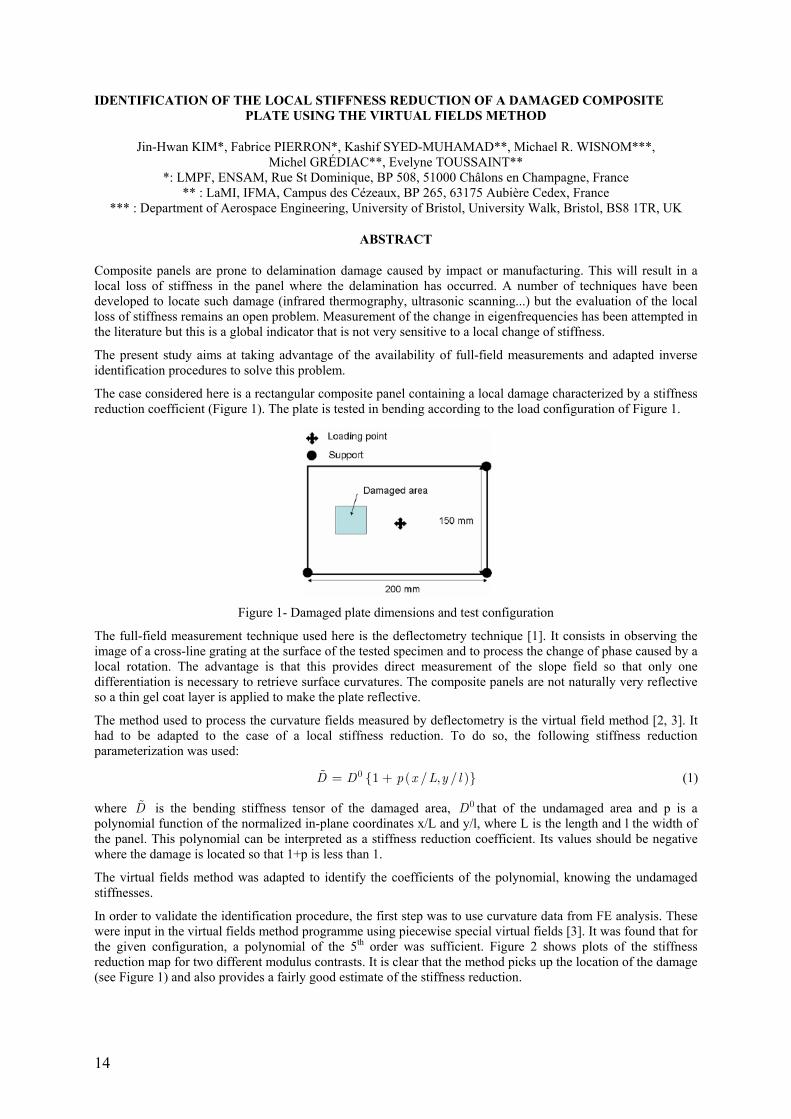
The case considered here is a rectangular composite panel containing a local damage characterized by a stiffness reduction coefficient (Figure 1). The plate is tested in bending according to the load configuration of Figure 1.
Figure 1- Damaged plate dimensions and test configuration
The full-field measurement technique used here is the deflectometry technique [1]. It consists in observing the image of a cross-line grating at the surface of the tested specimen and to process the change of phase caused by a local rotation. The advantage is that this provides direct measurement of the slope field so that only one differentiation is necessary to retrieve surface curvatures. The composite panels are not naturally very reflective so a thin gel coat layer is applied to make the plate reflective.
The method used to process the curvature fields measured by deflectometry is the virtual field method [2, 3]. It had to be adapted to the case of a local stiffness reduction. To do so, the following stiffness reduction parameterization was used:
( ) 0 1 / , /D D p x L y l= + (1)
where D is the bending stiffness tensor of the damaged area, 0D that of the undamaged area and p is a polynomial function of the normalized in-plane coordinates x/L and y/l, where L is the length and l the width of the panel. This polynomial can be interpreted as a stiffness reduction coefficient. Its values should be negative where the damage is located so that 1+p is less than 1.
The virtual fields method was adapted to identify the coefficients of the polynomial, knowing the undamaged stiffnesses.
In order to validate the identification procedure, the first step was to use curvature data from FE analysis. These were input in the virtual fields method programme using piecewise special virtual fields [3]. It was found that for the given configuration, a polynomial of the 5th order was sufficient. Figure 2 shows plots of the stiffness reduction map for two different modulus contrasts. It is clear that the method picks up the location of the damage (see Figure 1) and also provides a fairly good estimate of the stiffness reduction.

15
Figure 2- Example of identification of the stiffness reduction polynomial for different modulus contrast
(simulated curvatures).
The experimental implementation has been performed using a deflectometry set-up at the University of Bristol (Figure 3).
Figure 3- General view of the deflectometry set-up, camera and grating.
This set-up has been used for an undamaged plate of unidirectional T300/914 carbon-epoxy. The stiffnesses have been identified to within less than 5% of the reference parameters coming from the usual tensile and shear tests. The paper will present experimental results first for damaged plates with varying stiffness contrasts and damage size. The sensitivity of the method will be discussed.
REFERENCES
[1] Avril S., Grédiac, M., Pierron F., Surrel Y., "Deflectometry and virtual fields for identification of static plate bending stiffnesses", proceedings of Xth SEM International Congress on Experimental Mechanics (CD-ROM), 7-10 June in Costa Mesa, USA, 2004.
[2] Grédiac M., Toussaint E., Pierron F., "Special virtual fields for the direct determination of material parameters with the virtual fields method. 1- Principle and definition", International Journal of Solids and Structures, Vol. 39, n° 10, pp. 2691-2705, 2002.
[3] Grédiac M., Toussaint E., Pierron F., "Special virtual fields for the direct determination of material parameters with the virtual fields method. 3- Application to the bending rigidities of anisotropic plates", International Journal of Solids and Structures, Vol. 40, n° 10, pp. 2401-2419, 2003.
16
SIMULATION OF THE EFFECTS OF RESIDUAL STRESSES ON MATRIX CRACKING PROBABILITY OF UNIDIRECTIONAL LAMINAE OF CARBON REINFORCED EPOXIES
D. Trias, J. A. Mayugo, A. Turon, N. Blanco, J. Costa AMADE, Escola Politècnica Superior, Universitat de Girona, 17071 Girona, Spain
ABSTRACT
Usual manufacturing processes for glass and carbon fiber reinforced polymers end with a curing phase in which the polymerisation reaction of the matrix takes place. In this phase, the matrix shrinks and a complex stress-strain state is produced. This residual stresses may disappear partially during the life of the laminate, but generally it is accepted that they have to be considered in the failure behavior [1].
Some researchers have modelled and shown the influence of thermal stresses on the non-linear behavior [2, 3] and failure [4, 5].
In former works, a Statistical Representative Volume Element (SRVE) has been developed [6]. This SRVE allows the probabilistic simulation of matrix cracking in unidirectional laminae. If digital images from real materials are used to construct reallistic SRVEs the probability density function for any failure criteria can be obtained accurately and, using a two-scale method, applied to real life structural components [7].
The purpose of this work is to evaluate the effects of residual stresses on the probability of crack initiation. Simulations of the residual stress are performed at the microscopic level, using a Statistical Representative Volume Element which represents the real random microstructure of a UD carbon/epoxy laminate. A two-scale method is developed to obtain the probability density function of usual failure criteria for any macroscopical stress state and taking into account residual stresses.
REFERENCES
[1] J. A. Nairn. Application of fracture mechanics to polymers, adhesives and composites, volume 33 of European Structural Integrity, chapter Residual stress effects in fracture of composites and adhesives, pages 193-200. Elsevier, 2003.
[2] D. Perreux and D. Lazuardi. The effects of residual stress on the non-linear behaviour of composite laminates. Part I. Experimental results and residual-stress assessments. Composites Science and Technology, 61(2):167-175, 2001.
[3] D. Perreux and D. Lazuardi. The e®ects of residual stress on the non-linear behaviour of composite laminates. Part II. Layer, laminate non-linear models and the effect of residual stress on the model parameters. Composites Science and Technology, 61(2):167-175, 2001.
[4] B. Fiedler, M. Hojo, S. Ochiai, K. Schulte, and M. Ochi. Finite-element modeling of initial matrix failure in cfrp under static transverse tensile load. Composites Science and Technology, 61:95-105, 2001.

17
SIMULATION OF PROGRESSIVE DAMAGE DEVELOPMENT IN BRAIDED COMPOSITE TUBES UNDERGOING AXIAL CRUSHING
Carla McGregor, Reza Vaziri, and Anoush Poursartip Composites Group, Departments of Civil Engineering and Materials Engineering,
The University of British Columbia, Vancouver, B.C., Canada, V6T 1Z
Keywords: composite tube crushing, compressive failure, continuum damage mechanics
ABSTRACT
Composite tubular structures are of interest as viable energy absorbing components in vehicular front rail structures to improve crashworthiness [1-9]. Desirable tools in designing such structures are models capable of simulating damage growth in composite materials. Our model (CODAM for COmposite DAMage), which is a continuum damage mechanics based model for composite materials with physically based inputs, has shown promise in predicting the complete tensile behaviour from initiation of damage to complete failure [10-13]. This study focuses on extending the model to capture the complete compressive response of composite materials. Refinements to the model are based on the experimentally observed compressive failure mechanisms presented in the literature [14-19]. In particular, the mechanical consequences of kinking and kink band broadening, in conjunction with matrix cracking and delamination, are represented in the model. This is accomplished by including a plateau stress in the compressive stress strain response to account for the energy absorbed during band broadening. Model parameters defining the compressive response are related to experimentally observed behaviour, thus maintaining the physical basis of CODAM. The model was validated using results from tube crush experiments (Figure 1). The damage propagation, failure morphology and energy absorption predictions correlate well with the experimental results. A sensitivity analysis was carried out using the model to investigate which parameters had the strongest influence on the response. This paper will present the details of the constitutive model, comparisons between predicted and experimental tube crushing responses, and the results of the model sensitivity analysis.
Figure 1- (a) Predicted failure morphology and (b) comparison of predicted upper and lower bound force-
displacement profiles to the experimentally measured trace for single ply tube with plug. Experimental results provided by General Motors of Canada Ltd.
REFERENCES
[1] Thornton,P.H. and Edwards,P.J., "Energy Absorption in Composite Tubes", Journal of Composite Materials, Vol. 16, No. 6, pp. 512-545, 1982.
[2] Farley,G.L. and Jones,R.M., "Crushing Characteristics of Continuous Fibre-Reinforced Composite Tubes", Journal of Composite Materials, Vol. 26, No. 1, pp. 37-50, 1992.
[3] Farley,G.L., "Effect of Specimen Geometry on the Energy Absorption Capabilities of Composite Materials", Journal of Composite Materials, Vol. 20, No. 4, pp. 390-400, 1986.
[4] Farley,G.L., "Energy Absorption of Composite Materials", Journal of Composite Materials, Vol. 17, No. 3, pp. 267-279, 1983.
[5] Hull,D., "A Unified Approach to Progressive Crushing of Fibre-Reinforced Composite Tubes", Composite Science and Technology, Vol. 40, pp. 377-421, 1991.
18
[6] Beard,S.J. and Chang,F.K., "Energy Absorption of Braided Composite Tubes", International Journal of Crashworthiness, Vol. 7, No. 2, pp. 191-206, 2002.
[7] Karbhari,V.M. and Haller,J.E., "Rate and Architecture Effects on Progressive Crush of Braided Tubes", Composite Structures, Vol. 43, No. 2, pp. 93-108, 1998.
[8] Chiu,C.H., Tsai,K.-H., and Huang,W.J., "Effects of Braiding Parameters on Energy Absorption Capability of Triaxially Braided Composite Tubes", Journal of Composite Materials, Vol. 32, No. 21, pp. 1964-1983, 1998.
[9] Quek,S.C., Waas,A.M., Hoffman,J., and Agaram,V., "The Crushing Response of Braided and CSM Glass Reinforced Composite Tubes", Composite Structures, Vol. 52, No. 1, pp. 103-112, 2001.
[10] Williams, K. V., (1998). "A Physically-Based Continuum Damage Mechanics Model for Numerical Prediction of Damage Growth", Ph. D. Thesis, The University of British Columbia.
[11] Williams,K.V., Vaziri,R., and Poursartip,A., "A Physically Based Continuum Damage Mechanics Model for Thin Laminated Composite Structures", International Journal of Solids and Structures, Vol. 40, pp. 2267-2300, 2003.
[12] Floyd, A., (2004). "An engineering approach to the simulation of gross damage development in composite laminates", Ph.D. Thesis, Department of Civil Engineering, The University of British Columbia, Vancouver, BC, Canada.
[13] McClennan, S., (2005). "Crack Growth and Damage Modeling of Fibre Reinforced Polymer Composites", MASc. Thesis, Department of Materials Engineering, The University of British Columbia.
[14] Hahn,H.T. and Williams,J.G., "Compression Failure Mechanisms in Unidirectional Composites", ASTM Special Technical Publication, pp. 115-139, 1986.
[15] Sivashanker,S., "Damage Propagation in Multidirectional Composites Subjected to Compressive Loading", Metallurgical and Materials Transactions A-Physical Metallurgy and Materials Science, Vol. 32, No. 1, pp. 171-182, 2001.
[16] Sivashanker,S. and Bag,A., "Kink-Band Propagation in a Multi-Directional Carbon Fiber-Polymer Composite", Metallurgical and Materials Transactions A-Physical Metallurgy and Materials Science, Vol. 32, No. 12, pp. 3157-3160, 2001.
[17] Sivashanker,S., Fleck,N.A., and Sutcliffe,M.P.F., "Microbuckle Propagation in a Unidirectional Carbon Fibre-Epoxy Matrix Composite", acta materialia, Vol. 44, No. 7, pp. 2581-2590, 1996.
[18] Budiansky,B. and Fleck,N.A., "Compressive Failure of Fibre Composites", Journal of the Mechanics and Physics of Solids, Vol. 41, No. 1, pp. 183-211, 1993.
[19] Quek,S.C., Waas,A.M., Shahwan,K.W., and Agaram,V., "Compressive Response and Failure of Braided Textile Composites: Part 1 - Experiments", International Journal of Non-Linear Mechanics, Vol. 39, No. 4, pp. 635-648, 2003.

19
2D NUMERICAL SIMULATION OF GRP PIPES’ FAILURE UNDER RING LOAD CONDITION
Hugo Faria INEGI – Instituto de Engenharia Mecânica e Gestão Industrial
Leça do Balio – Portugal
Marcelo F. S. F. de Moura and Rui M. Guedes DEMEGI – Faculdade de Engenharia
Universidade do Porto Portugal
ABSTRACT
In piping systems, glass-fibre reinforced plastic (GRP) pipes have been increasingly introduced and are now an important class of engineering structures. However, the lack of understanding the fundamental parameters controlling failure mechanisms and long-term materials performance necessarily leads to over-design and inservice prototype evaluations and, furthermore, inhibits greater utilization. So, many of the composite materials applications have an empirical and/or experimental basis which doesn’t allow the recurrence to theoretical models in larger scale.
Algebraic formulations of the problems, such as Finite Element Analysis (FEA), approaching the relevant physical processes involved, are frequently used to simulate FRP structures’ behaviour.
Within this study, numerical models were developed in order to simulate the mechanical behaviour of a GRP pipe in a ring deflected condition. And that was, actually, its main objective: to evaluate the reproducibility of the damage mechanisms and global mechanics of these structures, verified in experimental campaigns, with numerical tools. The reference tests were the initial failure strain ones, conducted according to EN1226:1995, led on specimens with particular material constitutions and layering up.
For that purpose, a 2D model was created, based in the geometry and dimensions of the test specimens with 10 plies of 1.2mm thickness each, separated by interface cohesive finite elements [1-3] allowing simulation of delamination and rupture of fibres, either in mode I and/or mode II.
According to the specifications of the manufacturer, a 90º winding orientation angle was assumed and so the 2D model seemed to fit all the requirements for this study, once the main properties governing the mechanical behaviour act in each cross section plane. However, to verify those assumptions, simplified 3D models were firstly developed and influence of winding angle was analyzed.
Figure 1 shows the experimental setup apparatus, and figures 2 and 3 shows the typical results obtained either in experimental or numerical procedures, respectively.
Figure 1- Experimental setup for test campaign according to EN1226:1995.

20
Figure 2- Failure occurred in test specimen.
Figure 3- Failure reproduced with 2D numerical model.
It was verified that the numerical model presented good agreement relatively to the experimental results. The modeling methodologies implemented as well as the assumptions, parametric studies and results achieved are presented.
REFERENCES
[1] M. F. S. F. de Moura; J. P. M. Gonçalves; A. T. Marques; P. M. S. T. de Castro; Prediction of Compressive Strength of Carbon-Epoxy Laminates Containing Delamination by Using a Mixed-Mode Damage Model, Composite Structures, Vol. 50, Nº2, pg. 151-157, 2000.
[2] J. P. M. Gonçalves; M. F. S. F. de Moura; P. M. S. T. de Castro; A. T. Marques; Interface Element Including Point-to-Surface Constraints for Three-Dimensional Problems With Damage Propagation, Engineering Computations: International Journal for Computer-Aided Engineering and Software, Vol. 17, Nº1, pg. 28-47, 2000.
[3] M. F. S. F. de Moura; J. P. M. Gonçalves; A. T. Marques; P. M. S. Tavares de Castro; Modeling Compression Failure After Low Velocity Impact on Laminated Composites Using Interface Elements, Journal of Composite Materials, Vol. 31, Nº 15, pg. 1462-1479, 1997.

21
IDENTIFYING THE EFFECT OF SHEAR RESIDUAL STRESSES ON STRESS TRANSFER IN SINGLE SHORT FIBRE COMPOSITES USING PHOTOELASTICITY
Fangming Zhao and Frank Jones Ceramics and Composites Laboratory (CCL), Department of Engineering Materials,
The University of Sheffield United Kingdom
ABSTRACT
A direct consequence of the shrinkage of the polymeric matrix around the reinforcement during curing and cooling is the formation of residual stresses. These stresses exist on both the macroscopic and microscopic scales. Shear residual stresses at the interface between the fibre and matrix are particularly important since they may lead to premature interfacial fracture and thus significantly decrease the stress transfer. Measurement and prediction of residual stresses become therefore important in relation to production, design and performance of composite materials.
Phase-stepping photoelasticity has been employed to measure the shear stresses in matrices and at interface in fibre polymer composites [1, 2]. It has been found to be a particularly useful tool to determine the interfacial shear stresses for the initiation and propagation of a debond. Furthermore, the interphasal responses of single coated fibre composites under external load were characterised to evaluate quantitatively the interfacial adhesion at different curing temperatures [3]. These provide the possibility of determining the shear residual stresses at the interface.
The purpose of this research is to determine the shear residual stresses and identify its effect on stress transfer on micro-scale in single short fibre composites by phase-stepping photoelasticity.
Shrinkage stresses during cure and thermal stresses on cooling from a post cure temperature occur within fibre composites. When the composites consist of short fibres and polymeric matrices, the shrinkage of the resin and the mismatch of their thermal expansion coefficients result in compressive stresses acting on not only the fibre normal to the fibre -matrix interface but also the face-ends of the short fibres [3]. Photoelastic results show that the residual stresses delay the stress transfer to the fibres and therefore reduce the reinforcing ability of the fibres.
Furthermore, even though an epoxy resin containing a sapphire fibre with higher Young’s modulus (Ef = 380 GPa) is cured at room temperature, significant internal stresses can be induced at the fibre-matrix interface after several months [4], which lead to yield and debond at the interface. Figure 1 shows contour map of fringe order in the epoxy that was cured at room temperature for 4.5 months and contained a short sapphire fibre. It can be seen that there is a high stress concentration region in the resin matrix and at the interface in the neighbourhood of the fibre. The high stress concentration region did not appear in the first month and then formed gradually. We are measuring the stress in the fibre by means of fluorescent spectroscopy.
Figure 1- Contour map of fringe order in the cold-cured resin matrix in the vicinity of a short Sapphire fibre.

22
Figure 2 shows the relative distribution of fringe order at fibre-matrix interface. It can be seen that in the specimen experienced the long term curing of 4.5 months, the fringe order at fibre-end is not a maximum and there is a plateau on the curve, indicating a debonded occurred at the end and interfacial yield in the bonded region. Furthermore the yielded interface was debonded after 26 months. The composite interface near the fibreend experienced yielding and debonding because of the presence of these extra internal stresses.
Figure 2- The distribution of fringe order at the fibre-matrix interface for epoxy resin cured at room temperature
for 4.5 and 26 months.
REFERENCES
[1] Zhao, F.M., Hayes, S.A., Patterson, E.A., Young, R.J., Jones, F.R., “Measurement of micro stress fields in epoxy matrix around a fibre using phase-stepping automated photoelasticity”, Composites Science and Technology, Vol. 63, No. 12, pp. 1783-1787, 2003.
[2] Zhao, F.M., Martin, R.D.S., Hayes, S.A., Patterson, E.A., Young, R.J., Jones, F.R., “Photoelastic analysis of matrix stresses around a high modulus sapphire fibre by means of phase-stepping automated polariscope”, Composites Part A, Vol. 36, No. 2, pp. 229-244, 2005.
[3] Zhao, F.M., Liu, Z., Jones, F.R., “Interface formation between reactive functional groups on fibre surfaces and resin matrices under differing curing schedules”, in The Proceedings of ICCM15, Durban, 2005.
[4] Zhao, F.M., F.R. Jones., “ Quantifying the effect of shrinkage and thermal stresses on stress transfer in single fibre composites using phase-stepping photoelasticity”, in CD-ROM Proceedings of International Conference on Interfaces and Interphases in Multicomponent Materials, Lyon, France, September 2005.

23
RESIDUAL STRENGHT OF LAMINATED GRAPHITE-EPOXY COMPOSITE CIRCULAR PLATES DAMAGED BY TRANSVERSAL LOAD
Giangiacomo Minak Andrea Zucchelli
DIEM - Facoltà di Ingegneria Università degli Studi di Bologna
Italia
ABSTRACT
Fibre-reinforced composite materials are increasingly used in airframes and the tendency is to built the main fuselage in Carbon Fibre Reinforced Polymer (CFRP).In general CFRP has a wide application in light-weight structural members, because it is characterized by a high strength-to-weight and stiffness-to-weight ratio, but it is vulnerable to damage caused by transverse loads, such as those arising from indentation and impact loading. One of the main reasons that inhibits more widespread applications of composite materials is their lack of resistance to low velocity and low energy impact damage[1-3], particularly in the case of thermoset matrix like epoxy, while the probability of such loadings occurring during the manufacture, service or maintenance of composite structures is very high [4].
The research dealt with the correlation between damage and tensile residual strength in quasi-isotropic carbon fibre reinforced epoxy resin laminate loaded at the centre. Load was applied by means of a servo hydraulic machine and it was supposed to simulate a low velocity impact. The Acoustic Emission (AE) technique was used to detect damage progression. Tensile resistance after indentation was investigated and correlated with acoustic emissions parameters. This was been done for different lamination sequences on specimens cut from the damaged plates and for two different damage levels, one corresponding to the first load drop in the loaddisplacement curve[5] and to the complete perforation of the plate.
Composite plates square 250x250 mm graphite/epoxy laminates were studied; their thickness was 1.6 mm. They have been made in autoclave from pre-pregs by stacking eight unidirectional plies with quasi-isotropic orientations, [0°,90°,45°,-45°]s.
The specimens were placed in a circular clamping fixture with an internal diameter of 200 mm (Figure 1) and they were loaded at the centre by a hemispherical hardened steel ball with a radius 7 mm.
Figure 1- Fixture System.
A servo hydraulic Instron 8033 testing machine controlled by a MTS Teststar II system and equipped by a 25kN load cell was used. The specimens were loaded monotonically in control of displacement and the head speed was of 0.05mm/sec. The test were stopped after the penetration of the steel ball into the laminate or at the first load drop During the test, the AE has been monitored by a Physical Acoustic Corporation (PAC) PCI-DSP4 device with four transducers PAC R15 setting up the amplitude threshold at 40 dB.
After each quasi static test the damaged plate was sliced by a diamond saw in one of the different directions shown in figure 2. The indented zone was in the centre of these tensile specimens to be tested to find the residual tension strength of the laminate composite as a function of the stacking sequence.
The tensile specimens had the same geometry suggested by ASTM D 5766 for open hole testing of CFRP, a width of 40 mm and a length of 250 mm.

24
Figure 2- Tensile Specimen cut directions.
The first results show a good correlation between the integral of a function f [6] of acoustic energy released by the specimen during the transversal loading and its tensile residual strength (Figure 3).
This function is defined as f=Ln(Estiff/Eac) where Estiff is the energy provided by the servo-hydraulic machine and Eac is the acoustic energy released during the loading process.
Figure 3- Correlation between AE data and residual tensile strength.
This kind of correlation could give very usefull information in the case of real components subjected to impact loading and monitored by AE devices.
REFERENCES
[1] Abrate S, "Impact on laminated composite materials". Applied Mechanics Reviews, Vol. 44, No. 4, pp. 155–190, 1991.
[2] Abrate S, "Impact on laminated composites: recent advances". Applied Mechanics Reviews, Vol. 47, No. 11, pp. 517–544, 1994.
[3] Abrate S, "Impact on composite structures". Cambridge: Cambridge University Press, 1998.
[4] Hosur MV, Murty CRL, Ramamurthy TS, Shet A, "Estimation of impact-induced damage of CFRP laminates through ultrasonic imaging, NDT&E International, Vol. 31, No. 5, pp. 359-374, 1998.
[5] Cesari F., Dal Re V., Minak G., Zucchelli A., "Damage and residual strength of laminated carbonepoxy composite circular plates loaded at the centre", accepted for publication on Composite Part A, 2005.
[6] Zucchelli A, Dal Re V, "Experimental analysis of composite laminate progressive failure by AE monitoring", Proceedings ICEM12 - 12th International Conference on Experimental Mechanics, Bari, Italy, 2004.

25
EXPERIMENTAL AND NUMERICAL STRENGTH ANALYSIS OF MIXED METAL-COMPOSITE CRIMPED OR ADHESIVELY BONDED JOINTS
Alain Prenleloup, Thomas Gmür, Philippe Bonhôte and John Botsis School of Engineering (STI)
Ecole polytechnique fédérale de Lausanne (EPFL) Switzerland
Konstantin O. Papailiou
Sefag AG Elektrotechnische Spezialartikel 6102 Malters Switzerland
ABSTRACT
In comparison to single-material components, mixed metal-composite structural elements exhibit differences in the constitutive law, thermal or hydrothermal response and failure characteristics between the metal, the com-posite and the possible bonding layer. This introduces zones of high stresses that induce damage initiation and growth, leading to fracture onset and ultimately failure. Consequently, in order to use such composite-metal joints in an optimal way, a thorough characterization of their mechanical and failure behaviour is required.
Today, mixed composite-metal joints are increasingly applied in industrial equipments such as automotive, air-craft or electrical components. As a specific application of mixed joints encountered in high-voltage networks, silicon composite insulators with metal end-fittings manufactured for high-voltage transmission lines are now replacing conventional porcelain elements. These structures, however, need two metal end-fittings in order to transfer loads from the high-voltage conductor to the tower or the transformer. Two different designs are adopted according to whether the structure is loaded primarily in bending or in traction. In the first case, the insulator is chosen tubular with aluminium fittings bonded to the composite tube by an epoxy adhesive layer. In the second situation, a rod-type insulator is preferred where steel end-fittings are crimped to the composite rod with a radial compression by means of a hydraulic press until a sufficient plastic deformation is initiated in the metal. In this work, numerical simulations and experimental investigations of the stress distributions throughout the joints are performed in order to follow, up to failure, the damage progress in the joints under tensile loading or bending.
On the computational level, 3D solid finite element models of the entire joints have been constructed by using the commercially available Abaqus software. A full Tsai-Wu tensor failure criterion has been chosen for the damage analysis of the composite rod or tube, while the steel or aluminium for the end-fittings and the possible adhesive have been treated as elastic perfectly plastic materials. The values of the ultimate strengths in the com-posite have been taken from different sources in the literature for the tubes and directly derived from in-house performed standard strength tests for the rods. For the crimped insulators, a Coulomb contact law with a shear limit has in addition been adopted at the interfaces between the steel end-fitting and the composite rod, and nonlinear simulations have been carried out on this type of joints.
On the experimental level, two in-house designed test grids have been constructed in order to validate the nu-merical stress state and maximum load generated during the tensile loading of the crimped joints and the bending loading on the bonded joints (the crimping phase required for the assembly of the crimped joints is performed by the insulator manufacturer and is here not investigated experimentally). The measurement setups are composed of a 200-kN servo-hydraulic test frame with a controlled regulation loop, instrumented with an LVDT displace-ment transducer, an in-house developed load cell and several resistive strain gauges pasted at different locations on the composite and the outer surface of the end-fittings. For the failure study, a 6-channel acoustic emission system has been added to the test equipment to shed light in the process of damage activity on the joints as a function of the applied tensile or bending load.
Several crimped and adhesively bonded insulators have been investigated. Manufactured by Sefag, the compos-ite insulators used in this study are made mainly of an epoxy rod or tube reinforced with ECR-glass fibres. For the rod-type insulators, the 18.6mm-thick composite core is obtained by a pultrusion technique, while for the adhesively bonded insulators the 10-ply (0, [–38, 38]2, [–63, 63]2, –63) 5.8mm-thick hollow core (outer diameter of 93 mm) is fabricated with a filament winding technique. The elastic properties of the composite are evaluated with a dual numerical-experimental modal identification procedure and standard static tests. Classical characteri-zations by inspection of micrographs of various sections with an optical microscope and by complementary evaluations such as the fibre volume fraction estimation have also been carried out.
The stress analysis has shown that, for the bonded insulators under bending, a stress concentration appears near the bond end since the strong radial stiffness of the fitting induces in the composite high spurious radial and ra-dial-hoop stresses which are particularly prejudicial to the strength of the hollow core as they are practically or-
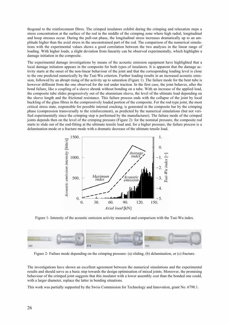
26
thogonal to the reinforcement fibres. The crimped insulators exhibit during the crimping and relaxation steps a stress concentration at the surface of the rod in the middle of the crimping zone where high radial, longitudinal and hoop stresses occur. During the pull-out phase, the longitudinal stress increases dramatically up to an am-plitude higher than the axial stress in the unconstrained part of the rod. The comparison of the numerical simula-tions with the experimental values shows a good correlation between the two analyses in the linear range of loading. With higher loads, a slight deviation from linearity can be observed experimentally, which highlights a damage initiation in the composite.
The experimental damage investigations by means of the acoustic emission equipment have highlighted that a local damage initiation appears in the composite for both types of insulators. It is apparent that the damage ac-tivity starts at the onset of the non-linear behaviour of the joint and that the corresponding loading level is close to the one predicted numerically by the Tsai-Wu criterion. Further loading results in an increased acoustic emis-sion, followed by an abrupt rising of the activity up to saturation (Figure 1). The failure mode for the bent tube is however different from the one observed for the rod under traction. In the first case, the joint behaves, after the bond failure, like a coupling of a sleeve shrunk without bonding on a tube. With an increase of the applied load, the composite tube slides progressively out of the aluminium sleeve, the level of the ultimate load depending on the sleeve length and the frictional resistance. This failure process ends with the collapse of the joint by local buckling of the glass fibres in the compressively loaded portion of the composite. For the rod-type joint, the most critical stress state, responsible for possible internal cracking, is generated in the composite bar by the crimping phase (compression transversally to the reinforcement), as predicted by the numerical simulations (but not veri-fied experimentally since the crimping step is performed by the manufacturer). The failure mode of the crimped joints depends then on the level of the crimping pressure (Figure 2): for the nominal pressure, the composite rod starts to slide out of the end-fitting at the ultimate tensile load and, for a higher pressure, the failure process is a delamination mode or a fracture mode with a dramatic decrease of the ultimate tensile load.
Figure 1- Intensity of the acoustic emission activity measured and comparison with the Tsai-Wu index.
Figure 2- Failure mode depending on the crimping pressure: (a) sliding, (b) delamination, or (c) fracture.
The investigations have shown an excellent agreement between the numerical simulations and the experimental results and should serve as a basic step towards the design optimisation of mixed joints. Moreover, the promising behaviour of the crimped joint suggests that this insulator with a lower assembly cost than the bonded one could, with a larger diameter, replace the latter in bending situations.
This work was partially supported by the Swiss Commission for Technology and Innovation, grant No. 6798.1.

27
EXPERIMENTAL STUDY AND NUMERICAL MODELLING OF SOLID AND HOLLOW FRPCONFINED CONCRETE MEMBERS
Danilo Bardaro Orazio Manni
Paolo Corvaglia Rossella Modarelli
Teresa Primo Department of Materials and Structural Engineering, CETMA Consortium
Cittadella della Ricerca, S.S. 7 km 706+030, 72100 Brindisi
ITALY
ABSTRACT
The use of Fiber Reinforced Polymer (FRP) materials as confining devices for concrete columns may produce remarkable increases of strength and ductility, as demonstrated by numerous published experimental and theoretical works [1-4].
On the other hand bridge piers are often designed as hollow-core reinforced concrete (RC) sections to obtain a reduction of the self-weight (especially in seismic zones) and a better structural efficiency in terms of strength/mass and stiffness/mass ratios. In contrast to this popularity in practice, scientific studies on the mechanical behaviour of such structural elements are limited [5], and the use of FRPs for external confinement of hollow core columns and piers is an almost unknown field at the moment.
In this research work both solid and hollow-core concrete specimens were tested under uniaxial compression to study the stress-strain relationship before and after FRP jacketing. A range of experimental parameters were investigated: different concrete strength, type of fibers, number of wrap layers, column shape and dimensions, and for square and rectangular sections, the corner radius and the cross-sectional aspect ratio.
Circular columns wrapped with FRP showed a significant increase in terms of both strength and ultimate displacements. Rectangular columns showed a lower increase in ultimate capacity, compared to circular sections. However the results related to ultimate axial displacement encourage adopting this technique for seismic retrofit to fulfill higher ductility requirements in both prismatic and cylindrical columns.
On the basis of the obtained experimental results, a parametric non-linear finite element model was developed and calibrated using ANSYS.
For the FRP-confined concrete the Drucker-Prager model, suitable for the simulation of granular materials, was used, while the FRP was modeled as a linear elastic orthotropic and transversely isotropic material.
The most convenient combination of element types was pointed out for the two different parts of the model, in terms of a compromise between accuracy and computational effort. The correct symmetries of the deformed shape of the model were achieved through the proper choice of the boundary conditions.
The model calibration was carried out through a sensitivity analysis performed on the Drucker-Prager parameters, which led to the individuation of the most appropriate values of such parameters for the actually investigated material and confinement type. A good correlation was finally achieved between experimental and numerical data in terms of stress-strain curves.
Once calibrated the model, it was parametrized and utilised in order to simulate the structural behaviour of the physical model for various geometric shapes and material properties, aiming at building handy design abacus for professional designers.
Figure 1 shows a hollow-core cylinder tested and the relative numerical model.

28
Figure 1- Numerical results for a hollow-core cylinder tested.
REFERENCES
[1] Harajli MH and Rteil AA, “Effect of Confinement Using Fiber-Reinforced Polymer or Fiber-Reinforced Concrete on Seismic Performance of Gravity Load-Designed Columns”, ACI Struct. Journ., Vol. 101, Issue 1, 2004, pp. 47-56.
[2] Rochette P and Labossière P, “Axial Testing of Rectangular Column Models Confined with Composites”, ASCE -J. Compos. for Constr., Volume 4, Issue 3, 2000, pp. 129-136.
[3] Teng JG and Lam L, “Compressive Behavior of Carbon Fiber Reinforced Polymer-Confined Concrete in Elliptical Columns”, ASCE - J. Struct. Engrg., Volume 128, Issue 12, 2002, pp. 1535-1543.
[4] Campione G, Miraglia N, Papia M, Influence of section shape and wrapping technique on the compressive behaviour of concrete columns confined with CFRP sheets, Proceedings of CCC2003 - Composites in Construction Int. Conf., September 16-19 2003, Cosenza, Italy, 301-306.
[5] Modarelli R., Micelli F., Manni O. “FRP-CONFINEMENT OF HOLLOW CONCRETE CYLINDERS AND PRISMS”, Proceedings of FRPRCS-7, November 6-9 2005, Kansas City, USA.

29
SESSION 2 – FRACTURE I
Chair: Prof. Ivana Partridge Cranfield University, United Kingdom
Monday 10th April 11:10 – 12:50
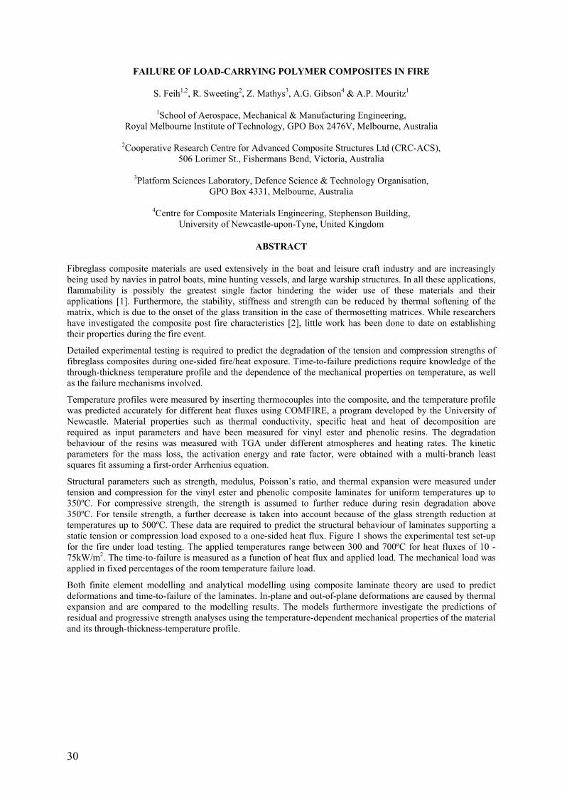
30
FAILURE OF LOAD-CARRYING POLYMER COMPOSITES IN FIRE
S. Feih1,2, R. Sweeting2, Z. Mathys3, A.G. Gibson4 & A.P. Mouritz1
1School of Aerospace, Mechanical & Manufacturing Engineering, Royal Melbourne Institute of Technology, GPO Box 2476V, Melbourne, Australia
2Cooperative Research Centre for Advanced Composite Structures Ltd (CRC-ACS),
506 Lorimer St., Fishermans Bend, Victoria, Australia
3Platform Sciences Laboratory, Defence Science & Technology Organisation, GPO Box 4331, Melbourne, Australia
4Centre for Composite Materials Engineering, Stephenson Building,
University of Newcastle-upon-Tyne, United Kingdom
ABSTRACT
Fibreglass composite materials are used extensively in the boat and leisure craft industry and are increasingly being used by navies in patrol boats, mine hunting vessels, and large warship structures. In all these applications, flammability is possibly the greatest single factor hindering the wider use of these materials and their applications [1]. Furthermore, the stability, stiffness and strength can be reduced by thermal softening of the matrix, which is due to the onset of the glass transition in the case of thermosetting matrices. While researchers have investigated the composite post fire characteristics [2], little work has been done to date on establishing their properties during the fire event.
Detailed experimental testing is required to predict the degradation of the tension and compression strengths of fibreglass composites during one-sided fire/heat exposure. Time-to-failure predictions require knowledge of the through-thickness temperature profile and the dependence of the mechanical properties on temperature, as well as the failure mechanisms involved.
Temperature profiles were measured by inserting thermocouples into the composite, and the temperature profile was predicted accurately for different heat fluxes using COMFIRE, a program developed by the University of Newcastle. Material properties such as thermal conductivity, specific heat and heat of decomposition are required as input parameters and have been measured for vinyl ester and phenolic resins. The degradation behaviour of the resins was measured with TGA under different atmospheres and heating rates. The kinetic parameters for the mass loss, the activation energy and rate factor, were obtained with a multi-branch least squares fit assuming a first-order Arrhenius equation.
Structural parameters such as strength, modulus, Poisson’s ratio, and thermal expansion were measured under tension and compression for the vinyl ester and phenolic composite laminates for uniform temperatures up to 350ºC. For compressive strength, the strength is assumed to further reduce during resin degradation above 350ºC. For tensile strength, a further decrease is taken into account because of the glass strength reduction at temperatures up to 500ºC. These data are required to predict the structural behaviour of laminates supporting a static tension or compression load exposed to a one-sided heat flux. Figure 1 shows the experimental test set-up for the fire under load testing. The applied temperatures range between 300 and 700ºC for heat fluxes of 10 - 75kW/m2. The time-to-failure is measured as a function of heat flux and applied load. The mechanical load was applied in fixed percentages of the room temperature failure load.
Both finite element modelling and analytical modelling using composite laminate theory are used to predict deformations and time-to-failure of the laminates. In-plane and out-of-plane deformations are caused by thermal expansion and are compared to the modelling results. The models furthermore investigate the predictions of residual and progressive strength analyses using the temperature-dependent mechanical properties of the material and its through-thickness-temperature profile.

31
Figure 1- Schematic & photograph of the fire-under-load test.
The bulk residual strength is calculated by averaging the mechanical properties in the through-the-thickness direction, while progressive failure models investigate the use of different failure criteria depending on the loading conditions (e.g. buckling failure criteria for compression). The tests reveal that the models can predict the time-to-failure characteristics with good accuracy. Figure 2 shows exemplary results of the residual strength approach in predicting time-to-failure under compressive loading for glass/vinyl ester laminates at different heat fluxes. Further experimental work on sandwich materials and the phenolic resin laminates is currently being undertaken to validate the models for a wider range of composite materials.
Figure 2- Predicted failure times for the GFRP laminate tested at different heat fluxes.
ACKNOWLEDGEMENTS
The study was funded by the United States Office of Naval Research (Grant No. N00014-04-10026). The authors thank Luke Bond (RMIT), Peter Tkatchyk (RMIT), Sarina Russo (DSTO), Paolo Corciulo (CRC-ACS) and Gary Mathys (DSTO) for assistance with property testing.
REFERENCES
[1] A.G. Gibson and J. Hume. ‘Fire performance of composite panels for large marine structures’. Plastics, Rubbers & Composites Processing and Applications, 23 (1995), 175-183.
[2] A.P. Mouritz and Z. Mathys. Post-fire mechanical properties of glass-reinforced polyester composites. Composite Science & Technology, 61 (2001), 475-490.

32
MEASURING THE FRACTURE TOUGHNESS FOR DIFFERENT FAILURE MODES IN LAMINATED COMPOSITES
S T Pinho, P Robinson and L Iannucci Department of Aeronautics, South Kensington Campus, Imperial College London, SW7 2AZ, U.K.
ABSTRACT
The use of a four point bend test is investigated for the measurement of intralaminar toughness of unidirectional T300/913 and HSC/SE84LV carbon-epoxy laminated composites. A key element of the investigation is the process of producing a sharp pre-crack and the effect of this on the measured toughness. Two different approaches [1] to introduce the pre-crack into the laminates during layup were investigated. In the first one, a plastic non-stick film was used to separate the two sides of the crack and in the second one, a metal blade coated with release agent was used. The second approach resulted in a method in which the pre-crack is produced during the layup and cure process and this is shown to cause minimal distortion of the plies of the laminate, Figure 1(a). The test results show good consistency and low scatter, and the fracture toughness measured is close to the mode I interlaminar fracture toughness for the same materials. The results seem to indicate that there is a correlation between ply distortion and an increased measured fracture toughness. However, for the specimens tested (all specimens had sharp crack tips and no damage ahead of the crack tip was present), this correlation is not strong. Using a plastic film to create a pre-crack does not yield a straight pre-crack, but the fracture toughness values obtained were found to be consistent with those obtained using the metal-blade approach to create the pre-crack.
The fracture toughnesses associated with fibre tensile failure and compressive fibre kinking in a T300/913 carbon-epoxy laminated composite are measured using compact tension and ‘compact compression’ [2] tests respectively, see Figure 1(b). The specimen strain fields were monitored using a digital speckle photogrammetry system during the tests. The damage present in the specimens after the tests was investigated using C-scan and optical and scanning electron microscopy. The initiation and propagation values of the tensile fibre failure fracture toughness were measured to be equal to 91.6 kJ/m2 and 133.5 kJ/m2 respectively. For fibre compressive kinking, an initiation value of 79.9 kJ/m2 was obtained, but no meaningful propagation values could be determined. In both cases, the test results showed low scatter.
Micrographs of the crack tip of a CT specimen are presented in Figure 1(c). For the CT specimens tested, crack growth was not smooth nor continuous: instead, several crack jumps of a few millimeters each time were observed, Figure 1(d). The R-curves obtained from the tensile tests are shown in Figure 1(e). The average fracture toughness obtained for initiation is 91.6 kJ/m2 with a standard deviation of 6.7%. Since the R-curves seem to converge after a ≈ 34mm, a propagation value for the fracture toughness can be defined. The average propagation fracture toughness is 133.5 kJ/m2 with a standard deviation of 15.7%. The R-curves obtained from the compressive tests are shown in Figure 1(e). The average fracture toughness obtained for initiation is 79.9 kJ/m2 with a standard deviation of 7.7%. Using the area method, the average propagation fracture toughness is 143.3 kJ/m2 with a standard deviation of 10.5%. Figure 1(f) shows a Scanning Electron Microscope (SEM) image of the typical fracture surface for a CT specimen. It is not an entirely planar fracture surface, as it exhibits a limited amount of fibre-pullout in the 0º plies. This study also shows that the data reduction process based on the stress intensity factor for isotropic materials [3] should not be used, and FE was found to be a valid alternative.
Acknowledgement. The funding of this research from the Portuguese Foundation for Science and Technology is greatfully acknowledged, as well as the help of Dr. Emile Greenhalgh and Ms. Victoria Bloodworth with the SEM.
REFERENCES
[1] S T Pinho, P Robinson, and L Iannucci. Intralaminar toughness tests of T300/913 carbon-epoxy. Technical report, Department of Aeronautics, Imperial College London, 2005.
[2] W C Jackson and J G Ratcliffe. Measurement of fracture energy for kink-band growth in sandwich specimens (paper no. 24). In Composites Testing and Model Identification, CompTest2004, University of Bristol, Bristol, UK, 21st-23rd September 2004.
[3] Standard Test Method for Plane-Strain Fracture Toughness of Metallic Materials. ASTM E399-90. Annual Book of ASTM Standards, 03.01:407–528, 1993.
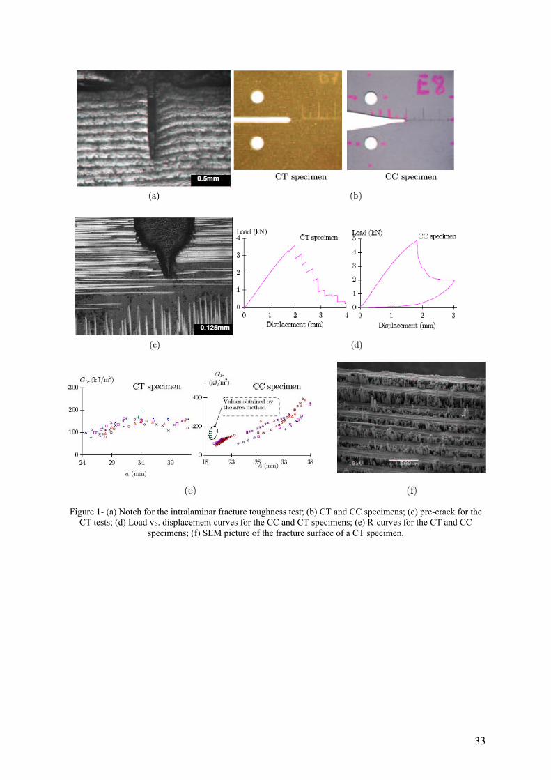
33
Figure 1- (a) Notch for the intralaminar fracture toughness test; (b) CT and CC specimens; (c) pre-crack for the
CT tests; (d) Load vs. displacement curves for the CC and CT specimens; (e) R-curves for the CT and CC specimens; (f) SEM picture of the fracture surface of a CT specimen.

34
INFLUENCE OF THE GEOMETRY OF THE SPECIMEN ON THE OCCURRENCE OF DELAMINATION DURING ADHESIVE JOINT TESTING
J.Costa, J.Renart, E.González, A.Turon AMADE- Escola Politècnica Superior
Universitat de Girona Campus Montilivi s/n. 17071 Girona
Spain
S.Lazcano Departamento de I+D. AIRBUS España
Av. John Lennon s/n. 28906 Getafe Spain
ABSTRACT
Adhesive joints between carbon fibre reinforced composite materials in aerospace industry are increasingly being applied to modern structures. The manufacturing procedures which include the use of adhesives, require extensive experimental testing in the different stages of the process. For instance, the quality of the adhesive and the compatibility with peel ply fabrics are checked upon the reception of the material by means of DCB (Double Cantilever Beam) tests on pre-cracked specimens. Later on, the assembly of structural parts by means of bonded or co-bonded adhesive joints goes along with the manufacture of panels, prepared exactly under the same conditions, that will be tested to assess the quality of the joint in the structure. Moreover, the high sensitivity of the quality of the joint to several manufacture operations such as surface preparation of the adherents, contamination, moisture, curing conditions, etc. should be taken into account. Therefore, the high number of specimens to be tested and the sensitivity of the quality of the joint to somehow uncontrollable parameters, raises the need of a reliable and repetitive test.
The DCB test is the most widely performed to obtain the mode I fracture toughness, GIC, of bonded joints. However, it is well known that the experimental results of the tests (GIC
exp: mode I fracture toughness derived from force-displacement curves) is sensitive to the geometry of the adherents, even though it conforms to the recommendations of the corresponding standards. This dependence is not anticipated by beam theory models which consider that the crack evolves in pure mode I irrespectively of the adherent thickness. This effect has already been reported for the adhesive joint testing between metallic materials. In this case, the dependence of the plastic deformation of the adhesive and metallic adherent on the specimen thickness is claimed to be at the origin of this effect [1]. Other authors, who investigated adhesive joints between metals, point to the existence of residual thermal stresses (which would depend on the sample thickness) to explain this phenomenon [2]. According to the knowledge of the authors of the present communication, no specific investigation has been published to describe and explain this dependence of DCB results on specimen geometry when testing adhesive joints between composite materials.
A particular characteristic of adhesive joints among composite materials is the possibility of the formation of delaminations (interlaminar cracks) during the test [3]. The initial pre-crack which is pretended to be placed in the centerline of the adhesive in order to promote a cohesive crack propagation, may evolve to a interlaminar crack away from the adhesive. Indeed, the fracture toughness for crack propagation in the adhesive (cohesive failure), or even, for propagation in the interface between the adhesive and the composite ply (adhesive failure), is commonly considerably higher than the fracture toughness for the delamination. Therefore, the crack path may evolve from the centerline of the adhesive to a delamination (it would not longer evolve in pure mode I) or, alternatively, some delamination (not visible) may be generated underneath the main crack in the adhesive. The consequence of this phenomenon is that the fracture energy involved in the test would raise due to an increase of damage processes and generated failure surface and, correspondingly, the experimentally determined fracture toughness of the adhesive, GIC
exp , would overcome the real one.
This communication presents the investigation performed to analyze the effect of the thickness of the composite adherents on the occurrence of delaminations during DCB tests of adhesive joints. Finite Element Modeling and the VCCT (Virtual Crack Closure Technique) have been used to simulate the adhesive joints (adherents and adhesive with pre-crack) and to estimate the stress concentration in the crack tip as well as the associated SERR (strain energy release rate), G, for different specimen geometries.
In qualitative good correspondence to the experimental results, it is demonstrated that higher adherent thicknesses are more likely to result in delaminations than thinner adherents. This phenomenon is considered to be a consequence of the stress constrain in the thinner adherent.

35
In addition, the critical defect size in the interlayer adjacent to the adhesive that results in a delamination instead of adhesive crack propagation has been found by means of the VCCT method. Finally, an iterative process has been applied to determine the progression of the adhesive crack and the delamination crack during the test. It was found that occasionally the delamination crack grows in the direction opposite to the main crack. A detailed description of the evolution of the complex scenario of an adhesive crack growing together with a delamination has been achieved. See Figure 1.
Figure 1- Evolution of a DCB specimen test with a main crack in the adhesive and a small flaw in the adjacent
interlayer
REFERENCES
[1] Ferracin T, Landis CM, Delannay F, Pardoen T, On the determination of the cohesive zone properties of an adhesive layer from the analysis of the wedge-peel test. International Journal of Solids and Structures Vol. 40, Nº 11, pp. 2889-2904 (2003).
[2] Daghyani HR, Ye L, Mai YW, Effect of thermal residual stresses on the crack path in adhesively bonded joints, J. Mater. Sci, Vol. 31, Nº 10, pp. 2523-2529 (1996).
[3] Chai H, On the Correlation between the Mode-I Failure of Adhesive Joints and Laminated Composites, Eng.Fract.Mech., Vol. 24, Nº 3, pp. 413 (1986).

36
EXPERIMENTAL AND NUMERICAL STUDIES OF MODE I, II, III AND MIXED-MODE I-II ENERGY RELEASE RATE IN LAMINATES
Rosa Marat-Mendes1, M. de Freitas2 1Department of Mechanical Engineering, Escola Superior de Tecnologia de Setúbal, Setúbal, Portugal.
[email protected] 2Department of Mechanical Engineering, Instituto Superior Técnico, Lisboa, Portugal.
ABSTRACT
Lamination of composite structures is one of the most common manufacturing techniques used in the construction of composite components. As the applications of composites expand, the use of laminated components in primary structures is becoming more prevalent. One of the limiting factors of laminated structures is a failure mode known as delamination which is the most common reason for laminated composite component failure and is the separation of individual layers of the laminated structure.
This paper reports an experimental study on the mode I, mode II, mode III and mixed-mode I-II interlaminar fracture toughness of unidirectional glass fibre reinforced polymer matrix composites. A double cantilever beam (DCB), an end notch flexure (ENF) and an edge cracked torsion (ECT) test procedurewere used respectively to characterize mode I, mode II and mode III fracture toughness (GIc, GIIc and GIIIc) using the procedure established on the recommended practices [1]. In order to characterize the mixed mode fracture a mixed-mode bending (MMB) test procedure was used to measure the mixed-mode I-II fracture toughness under a wide range of ratios GI/GII.
These tests were performed using a unidirectional laminate [024] and quasi-isotropic laminates [(-45/90/+45/0)3]s of glass fibre reinforced epoxy with an initial delamination in the midplane of the laminate for DCB, ENF and MMB specimens. For the tests under mode III loading a composite laminate [90/(±45)3/(∓45)3/90]s made of unidirectional glass fibre reinforced epoxy was used according to the proposed procedure in the literature for the ECT specimen. The delamination was artificially induced using a 13μm thickness Teflon foil during cure of the specimen.
A numerical study using a solid 3D finite element analysis using Virtual Crack Closure Technique (VCCT) and Beam theory was also performed to obtain the interlaminar critical strain energy release rate [2].
Figure 1 shows the comparison of different data reduction methods for beam theory (modified beam theory (MBT), the compliance calibration method (CC) and the modified compliance calibration method (MCC)), the virtual crack closure (VCCT) by Ribiki-Kanninen and experimental results.
Figure 1- Delamination Resistance Curve (R Curve) from DCB Test for experimental, beam theory and virtual
crack closure results.

37
The numerical studies, applying the Ribiki-Kanninen and the Beam theory method of strain energy calculation, showed a good correlation with the experimental analysis and the classic methods of mode partitioning [3].
Figure 2 shows the distribution of mode I, mode II and mixed-mode for experimental and analytical results. The analytical results were obtained using finite element analysis by ANSYS.
Figure 2- Comparison of mode I, mode II and mixed-mode I-II experimentally and analytical.
REFERENCES
[1] Adams, D., Carlson, L. and Pipes, R. (2003). Experimental characterization of advanced composite materials. Third Edition. CRC Press.
[2] Krueger R. (2002). The virtual crack closure technique - history, approach and applications. NASA/CR-2002-211628, Virginia.
[3] Marat-Mendes, R., Freitas, M. (2004) A testing procedure for Mixed mode delamination of composite materials. Proceedings of the 9th Portuguese conference on fracture, ESTSetúbal, Portugal, 18-20 February 2004. pp. 247-251.


39
SESSION 3 – STRUCTURES
Chair: Dr. Carlos G. Dávila NASA Langley Research Center, USA
Monday 10th April 14:00 – 15:40

40
MULTISCALE ANALYSIS OF THE STRAIN RATE EFFECT ON THE BEHAVIOUR AND DAMAGE OF COMPOSITE MATERIALS
Didier Batiste ENSAM École Nationale Supérieure d'Arts et Métiers, France
ABSTRACT
The evolution of the damage mechanisms occurring at the micro scale for a strain rate range between 10-4 and 350 s-1 is presented. The evolution of microcracks is compared to the decrease of the Young modulus on the specimen loaded on a high speed tensile machine (20 m/s). The quantitative data at the micro scale is used in a micro macro model (Mori and Tanaka) to predict the macroscopic behaviour of the composite. Experimental results at two scales and the homogenisation model are combined to lead to physical anisotropic viscodamage behaviour laws. Illustrations will be given on different composites: glass polyester laminate, carbon epoxy laminate and SMC.

41
CONTRIBUTION TO COMPOSITE ‘T’ BEAM DESIGN IN INDUSTRIAL ENVIRONMENT BY USING THE GRID TECHNIQUE
J. Molimard, A. Vautrin Mechanical and Materials Department
École Nationale Supérieure des Mines de Saint-Étienne 158, cours Fauriel, 42013, SAINT-ÉTIENNE Cedex 2
France
J. M. Béraud, P. Henrat Research & Technology Reinforcements
HEXCEL REINFORCEMENTS Z.I. Les Nappes
38630 LES AVENIÉRES France
ABSTRACT
The paper focuses on the advantage to use a full-field technique when designing a part in composite materials. The actual structure is a composite beam with a ‘T’ cross-section which is intended to replace a similar beam made of light alloys and acting as an aircraft wing stiffener. The interest to use advanced composites here is to save weight. Moreover, composites should also reduce the component cost; therefore a solution based on preform injection moulding process has been selected. Since the overall shape of the beam was previously fixed, the main question was to select the fibre preforms and the way to design and assembly the preforms to reach acceptable properties.
Firstly, a reference tensile test on ‘T’ shaped beam specimens is developed to compare the various solutions. The test should be simple enough but representative of the main loading of the part. Simplicity and flexibility of the testing approach are required when different solutions are to be investigated at the beginning of the design process. However, any rational comparison of structural performances has to be based on well-defined mechanical variables leading to quantitative data with uncertainties. Usually, industry is interested in overall quantities such as the stiffness and strength of the structure, those quantities being difficult to define accurately. The component part being complex and the goal being the optimisation of it, there is a need for more accurate characterization such as the localization of the first macro-damage. Obviously, the utilization of full-field methods would be both efficient and time saving.
‘T’ beam in composites Tensile test on a ‘T’ beam specimen
Secondly, it is shown that the grid method [1] [2] can be easily implemented in any industrial R&D laboratory since it relies on classical operations: gauge or grid bonding and image acquisition, and only basic knowledge is required to calibrate the set-up and evaluate metrological parameters, such as the resolution or the spatial resolution. Moreover, since it is a geometric method similar to well-known moiré it belongs to the usual culture of people in charge of mechanical tests. It is shown that the full-field method revealed the complexity of the test and led to an improvement of it before giving information on the tensile behaviour of the specimen. Then, the occurrence of the first macroscopic crack on the specimen edge was shown to be in agreement with the conventional first cracking load, based on the differentiation of the loading stress-strain curve. Finally, the localization and 2D full-field displacement measurement gave a first information on the damage mechanisms

42
linked to the méso-structure of the specimen. In the present case, the use of three different preforms to build up the ‘T’ shaped cross-section give rise to a complex assembly which generated both interlaminar shear and fibre-matrix transverse tension.
The full-field technique permitted refined comparison between different preform assemblies: standard and z-pinned ‘T’ specimens have been tested to quantify the gain in properties which can be drawn from the z-pin assembly technique [3]. The grid method proved there is a load transfer to the z-pins but the first cracking load did not seem to be significantly modified, however a refined analysis would be necessary in the future to quantify the effects of various parameters such as z-pin diameter, z-pin surface treatment, density and arrangement. The only obvious effect of the z-pins is to highly increase of the toughness of the specimen.
Finally, a FE 2D analysis has been carried out with ABAQUS code to strengthen the experimental approach. The numerical analysis is not so easy to perform since the transverse material properties are needed and the structure of the preform is very complex. Any further modelling would require 3D local and global analysis and development of specific characterization tests. The numerical simulation was shown to be in reasonable agreement with the experimental results and confirmed the effect of the displacements occurring within the grips.
In conclusion, this experimental approach proved the efficiency of full-field techniques, especially when structural parts are tested. Those techniques give information on the quality of the test and allow the localization of the first macro-crack. This type of information is not so usual in industry; in the present case it is shown that it is capital since new routes to optimise the part can be provided. However, to be routinely utilized in industrial R&D laboratories, the technique should be in agreement with the usual in-house practices. This is the reason why the grid method has been introduced. It is proved that such a technique can be easily implemented when refined information is needed during the optimisation process.
REFERENCES
[1] Y. SURREL Moiré and Grid Methods in Optics. SPIE, 2342, 1994, pp. 213-220.
[2] AVRIL S., VAUTRIN A. and SURREL Y., Grid Method: Application to the Characterization of Cracks, Experimental Mechanics, Vol. 44, n° 1, pp. 37-43, February 2004.
[3] E. GREENHALGH, M. HILEY. The assessment of novel materials and processes for the impact tolerant design of stiffened composite aerospace structures. Elsevier Composites Part A : applied science and manufacturing Vol. 34, 2003, p.151-161.

43
OPTIMIZATION OF COMPOSITE MATERIALS AND STRUCTURES FOR RACING MULTI-HULL YACHTS
N. Baral1, P. Davies2, D. Cartié3, C. Baley4 1Trimaran GROUPAMA, 2IFREMER, 3Cranfield University, 4Université de Bretagne Sud
ABSTRACT
Background:
Following a reduction in reliability of ocean racing multi-hulls as performance increased, the technical team of the Groupama trimaran (skippered by Franck Cammas) launched a research campaign in collaboration with IFREMER Brest, the University of South Brittany and Cranfield University (U.K.). The aim was to develop and qualify high performance composites for nautical use.
The programme is based on the characterization of high modulus carbon fibres and the study of innovative solutions to improve their composites, together with a study of the impact behaviour of these composites in sandwich materials under impact loading. This contribution will present results from the test programme and discuss the difficulties associated with testing very stiff composites.
High modulus carbon composites
Physico-chemical and basic mechanical properties (tension, flexure and short beam shear) of specimens produced from unidirectional prepreg with PAN (M40J, M46J, M55J) and pitch (K637) fibres, produced using both oven and autoclave routes, have been determined. Then the crack propagation resistance of DCB and MMB specimens was examined. This has enabled the parameters affecting defect sensitivity to be quantified. An example of results is shown below. The application of standard mode I and mixed mode tests to these very high stiffness specimens requires care and will be discussed in detail.
Figure 1- Mode I interlaminar fracture resistance of high modulus carbon UD fibre composites

44
Extensive optical and scanning electron microscopy enabled fracture mechanisms to be more clearly understood.
In parallel with these tests the use of through-thickness reinforcement (Z-pinning) was studied for specimens reinforced with M46J fibres. Pinning results in significant increases in fracture energy but again test analysis requires care. This solution appears very promising for local reinforcement of highly loaded regions, notably around holes and cutouts.
Impact on sandwich panels
Having characterized the carbon/epoxy materials which make up the skins, the second part of the study examined the impact behaviour of sandwich panels. The aim is to improve the damage tolerance of sandwich with foam or honeycomb cores used for floats or cross-beams. A special test was developed involving dropping a weighted medicine ball from increasing heights onto sandwich panels, Photo 1.
Photo 1- Impact test set-up
This study has allowed different sandwich concepts to be evaluated but extensive instrumentation (high speed digital camera, laser displacement transducer, strain gauges) has also resulted in an improved understanding of the impact process and provided data for correlation with FE modelling, e.g. Figure 2.
Figure 2- Lower skin deflection during 1m drop of 19kg soft impacter.

45
POSTER SESSION 2
Monday 10th April 15:40 – 16:25

46
STATIC TESTING OF CROSS-SECTION OF WIND TURBINE BLADE
Kim Branner Wind Energy Department Risø National Laboratory
Denmark
ABSTRACT
Many modern wind turbine blades are constructed with a load-carrying box girder that supports the outer shell. The purpose of the box girder is to give the blade sufficient strength and stiffness, both globally and locally. Globally, the blade should be sufficiently stiff in order not to collide with the tower during operational loading. Locally, the box girder, together with the stiffness of the outer shell, ensures that the shape of the aerodynamic profile is maintained.
The pressure and gravity load on the blade results in edgewise and flapwise bending, as well as torsional loading of the blade. The box girder primarily carries the flapwise and torsional loads, while the edgewise bending is carried mainly by strengthening the leading and trailing edges of the aerodynamic profile. In flapwise bending, one side of the box girder is in compression and one side in tension. The compressive loading may cause the flange to fail in buckling. It is well known that the boundary conditions have a large influence on the buckling strength of a panel. For the box girder, the transverse properties of the corner and web represent the boundary condition of the flange. The purpose of the investigations presented here is to measure transverse properties of a box girder experimentally in order to investigate how well different finite element models predict these transverse properties. This is expected to result in recommendations for how buckling of wind turbine blades can be predicted using FEM. Comparison between shell and solid FE-models has previously been done by Pardo & Branner [1] assuming isotropic material.
Figure 1- Test setup. The top is fixed and the bottom with the two supports is moving upward during loading.
The tests are performed in displacement control using a 250 kN Instron material testing machine. The test setup is shown in Figure 1. The upwind side (bottom flange) is supported by two cylinders symmetrical about the midplane. The downwind side (top flange) is loaded by a cylinder in the midplane. Both the support and loading cylinders are slightly angled in order to account for the longitudinal tapering of the box girder. Three specimens cut from the load carrying box girder of a 25m wind turbine blade were tested and deformations and strains were measured. The specimens have different depths, but only little difference is seen for the measurements.
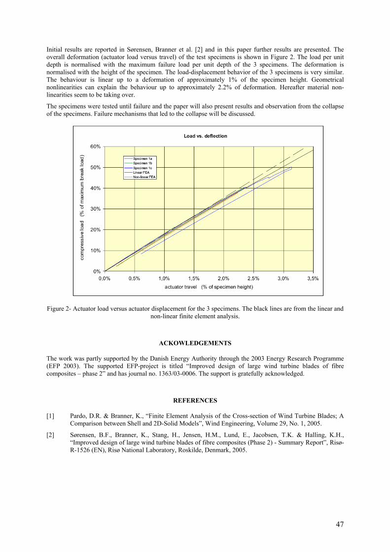
47
Initial results are reported in Sørensen, Branner et al. [2] and in this paper further results are presented. The overall deformation (actuator load versus travel) of the test specimens is shown in Figure 2. The load per unit depth is normalised with the maximum failure load per unit depth of the 3 specimens. The deformation is normalised with the height of the specimen. The load-displacement behavior of the 3 specimens is very similar. The behaviour is linear up to a deformation of approximately 1% of the specimen height. Geometrical nonlinearities can explain the behaviour up to approximately 2.2% of deformation. Hereafter material non-linearities seem to be taking over.
The specimens were tested until failure and the paper will also present results and observation from the collapse of the specimens. Failure mechanisms that led to the collapse will be discussed.
Figure 2- Actuator load versus actuator displacement for the 3 specimens. The black lines are from the linear and
non-linear finite element analysis.
ACKOWLEDGEMENTS
The work was partly supported by the Danish Energy Authority through the 2003 Energy Research Programme (EFP 2003). The supported EFP-project is titled “Improved design of large wind turbine blades of fibre composites – phase 2” and has journal no. 1363/03-0006. The support is gratefully acknowledged.
REFERENCES
[1] Pardo, D.R. & Branner, K., “Finite Element Analysis of the Cross-section of Wind Turbine Blades; A Comparison between Shell and 2D-Solid Models”, Wind Engineering, Volume 29, No. 1, 2005.
[2] Sørensen, B.F., Branner, K., Stang, H., Jensen, H.M., Lund, E., Jacobsen, T.K. & Halling, K.H., “Improved design of large wind turbine blades of fibre composites (Phase 2) - Summary Report”, Risø-R-1526 (EN), Risø National Laboratory, Roskilde, Denmark, 2005.
48
CONTINUOUS FIBRE COMPOSITES WITH A NANOCOMPOSITE MATRIX
Daniel P. N. Vlasveld and Stephen J. Picken Nanostructured materials - Faculty of Applied Sciences
Delft University of Technology The Netherlands
Harald E. N. Bersee
Design and Production of Composite Structures - Faculty of Aerospace Engineering Delft University of Technology
The Netherlands
ABSTRACT
Until recently the world of continuous fibre reinforced composites and the world of nanocomposites have been evolving separately. We have developed a new type of multi-scale composite, which combines continuous fibre reinforcement with a thermoplastic nanocomposite matrix material. The micrometer length-scale of the fibres and the nanometer length-scale of the matrix reinforcement enable the combination of reinforcement on two levels (Figure 1). We have shown in a PA6-matrix fibre composite that the use of nanocomposites as matrix material can significantly increase the compressive and flexural strength of the fibre composite, due to the much higher matrix modulus [1]. This positive effect of the nanocomposite matrix on the strength is especially important at elevated temperatures and in high humidity environments. It has been shown that with the nanocomposite matrix the fibre composite has up to 40% higher flexural strength at elevated temperatures (Figure 2). This also means that the new composite retains some strength at temperatures that are up to 50 ºC higher. In contrast to the use of different matrix polymers to improve the high temperature behaviour, the use of nanocomposites can be implemented without any change in the processing temperature. Therefore, this is a very cost-effective method to increase the maximum use temperature.
While the idea of using a nanocomposite as the matrix of a fibre reinforced composite may be simple, in reality it is not so easy to produce a three-phase composite that shows the desired increase of the strength due to several complications. Indeed, the concept has been investigated before without much success [2]. The expected increase in strength can only be achieved if all other factors, such as void content, fibre wetting and adhesion, remain unaffected. This is, unfortunately, often not the case.
For example, using a single fibre fragmentation test, we have shown that the adhesion with the fibres is often lower with nanocomposites than with the unfilled matrix polymer [3].
An important problem with nanocomposites as matrix materials is the increased melt viscosity, compared to unfilled polymers. In addition, a melt yield stress can occur due to the formation of a particle network. This melt flow behaviour is obviously a disadvantage for the use as thermoplastic fibre composite matrix, because it complicates the fibre bundle impregnation and fibre wetting.
To understand and solve this problem, the influence of the shape of the reinforcing particles in the nanocomposite, especially the aspect ratio, on the melt flow behaviour and the mechanical properties has been studied [4].
In this paper we will show how we have used a combination of experimental data obtained from mechanical tests, moisture diffusion tests and rheological tests in combination with several simple models to determine the average particle aspect ratio in the nanocomposites. In addition, WAXS and DSC were used to determine other important model parameters, such as particle orientation and matrix crystallinity.
The results of the tests and the models have shown how the particle modification and production process influence the average aspect ratio in the nanocomposites. This also shows that properties that are beneficial for the mechanical properties can cause fibre impregnation to deteriorate. Therefore, a compromise has to be found. With the new understanding of how the particles influence the nanocomposite matrix a material could be selected that indeed results in the predicted increase in the fibre composite strength.
The experimental results of the nanocomposite and the fibre composite will be discussed, in combination with the models that can explain how the nanocomposite influences the properties of the fibre composite.

49
Figure 1- The new three-phase composite: nm thin silicate layers (left, TEM) can fit between μm sized fibres in a
continuous fibre reinforced composite (right, SEM). They lead to a large increase of the matrix modulus, also above Tg.
Figure 2- Fibre composite with nanocomposite matrix shows large increase in flexural strength.
REFERENCES
[1] Vlasveld, D.P.N., Bersee, H.E.N., Picken, S.J., "Nanocomposite matrix for increased fibre composite strength", Polymer, In press, 2005.
[2] Rice B.P., Chen C.G., Cloos L., Curliss D., "Carbon fibre composites: Organoclay-aerospace epoxy nanocomposites, Part 1", Sampe Journal, Vol. 37, Issue 5, pp. 7-9, 2001.
[3] Vlasveld, D.P.N., Parlevliet, P.P., Bersee, H.E.N., Picken, S.J., "Fibre–matrix adhesion in glass-fibre reinforced polyamide-6 silicate nanocomposites.", Composites Part A: Applied Science and Manufacturing, Vol. 36, Issue 1, pp. 1-11, 2005.
[4] Vlasveld, D.P.N., Jong, M. de, Bersee, H.E.N., Gotsis, A.D., Picken, S.J., "The relation between rheological and mechanical properties of PA 6 nano- and micro-composites". Polymer, In press, 2005.
Contact: [email protected] Tel: 0031-152788013 Fax: 0031-1527887415

50
FRACTURE TOUGHNESS OF SKIN/CORE INTERFACES IN SANDWICH MATERIALS UNDER MIXED MODE LOADINGS
Christian Lundsgaard-Larsen1, Rasmus C. Østergaard2, Bent F. Sørensen2 and Christian Berggreen1
1Department of Mechanical Engineering Technical University of Denmark
DK-2800 Kgs. Lyngby Denmark
2Materials Research Department
Risø National Laboratory DK-4000 Roskilde
Denmark
ABSTRACT
Defects in sandwich structures are often inevitable and can originate both from manufacture and use. An important defect type is debonding, i.e. areas with weak or no adhesion between skin and core. In a sandwich structure debondings can arise in production when an area between skin and core has not been wetted properly resulting in a lack of adhesion. In use, damages from loads e.g. impact might result in formation of a debond crack. With debonds present the structure might fail under loads significantly lower than those for the intact sandwich structure. In order to improve the damage tolerance of sandwich structures an increase in the toughness between skin and core is necessary [1].
It is believed that the microstructure of the interface between skin and core can have a large effect on the fracture toughness. It has been shown that the presence of a mat with random oriented and loosely packed fibers between the core and the laminate facilitates the formation of large scale fiber bridging, resulting in a significant increase in crack resistance [2]. The formation of large scale fiber bridging results in a fracture process zone with length several times the skin height. To characterize the crack growth resistance the J integral is deployed since it is valid for handling fracture with large fracture process zone. By analytical derivation the J integral is determined for the special sandwich specimens used in the tests [3].
The aim of the current work is to establish a more fundamental understanding of sandwich fracture and mechanisms taking place during fracture. Several conditions have an influence on the fracture mechanisms and nominal fracture toughness e.g. mode mixity of the loading, skin lay-up, resin type and core density. In the experimental part of this study we measure the fracture toughness of the skin/core interfaces for one material combination by loading specimens under different mode mixities. Observations during experiments are used to identify mechanisms related with variation in fracture toughness for the different mode mixities.
Specimens are manufactured by an industrial partner, with materials and thicknesses similar to those used in structural components. The sandwich consists of 2.5 mm thick glassfiber/polyester skins and 20 mm thick PVC foam core with density 80 kg/m3. A teflon film strip is placed between skin and core during manufacture to have a well defined start crack. The build-up configuration of the skins is (0/90, Unifilo®, ±45, CSM), where the CSM (chopped strand mat) laminae is located next to the core. The Unifilo and CSM laminaes consist of continuous fibers oriented randomly. The biaxial mat (0/90 and ±45) is 0.7 mm thick and has an area density of 600 g/m2. The Unifilo and CSM laminaes are 0.7 mm and 0.4 mm thick respectively and have an area density of 450 g/m2 and 300 g/m2 respectively. The overall dimensions of the sandwich specimens are 25 mm thick, 30 mm wide and 450 mm in length.
The test method is based on loading the sandwich specimen by uneven bending moments, see Figure 1. By varying the moments the ratio between tangential and normal crack opening displacement can be varied in the full mode mixity range. The loading by moments has the advantage that stable crack growth is accommodated because the J integral value is independent of the crack length. The moments are applied by vertical forces acting on two horizontal arms attached to the top of the specimen. The forces are applied by a roller/wire system mounted in a tensile test machine.
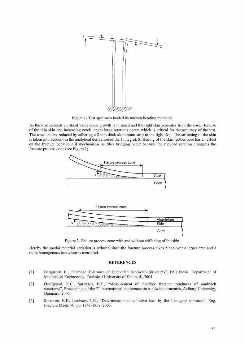
51
Figure 1- Test specimen loaded by uneven bending moments.
As the load exceeds a critical value crack growth is initiated and the right skin separates from the core. Because of the thin skin and increasing crack length large rotations occur, which is critical for the accuracy of the test. The rotations are reduced by adhering a 2 mm thick aluminium strip to the right skin. The stiffening of the skin is taken into account in the analytical derivation of the J integral. Stiffening of the skin furthermore has an effect on the fracture behaviour if mechanisms as fiber bridging occur because the reduced rotation elongates the fracture process zone (see Figure 2).
Figure 2- Failure process zone with and without stiffening of the skin.
Hereby the spatial material variation is reduced since the fracture process takes place over a larger area and a more homogenous behaviour is measured.
REFERENCES
[1] Berggreen, C., “Damage Tolerance of Debonded Sandwich Structures”, PhD thesis, Department of Mechanical Engineering, Technical University of Denmark, 2004.
[2] Østergaard, R.C., Sørensen, B.F., “Measurement of interface fracture toughness of sandwich structures”, Proceedings of the 7th international conference on sandwich structures, Aalborg University, Denmark, 2005.
[3] Sørensen, B.F., Jacobsen, T.K., “Determination of cohesive laws by the J integral approach”, Eng. Fracture Mech. 70, pp. 1841-1858, 2003.
52
EXPERIMENTAL ANALYSIS OF THE VARIABLE MIXED-MODE FATIGUE DELAMINATION IN A CARBON FIBRE-EPOXY LAMINATE
Norbert Blanco, Josep Costa Advanced Materials and Analysis for Structural Design
University of Girona E-17071 Girona
Spain
E. Kristofer Gamstedt KTH Solid Mechanics
Royal Institute of Technology SE-100 44 Stockholm
Sweden
Leif E. Asp Damage Tolerance Group
SICOMP AB SE-431 22 Mölndal
Sweden
ABSTRACT
Failure of composite laminates involves different damage mechanisms that result in the degradation of the material. One of the most important damage mechanisms, commonly referred to as delamination or interlaminar crack, is caused by the debonding of two adjacent plies of the laminate. In aeronautical applications, composite plates are sensitive to impact, and delamination occurs readily in composite laminates on impact. If the composite structure is subsequently loaded in compression, delaminations are likely to grow in varying crack propagation mode and eventually cause structural failure by buckling [1]. Many composite components have curved shapes, tapered thickness and plies with different orientations, which will also make the interlaminar crack grow with a mode mix that depends on the extent of the crack. Thus, interlaminar cracks in composite laminates generally grow under varying mixed-mode conditions.
On the one hand, delaminations are commonly studied in laboratory conditions by using the double cantilever beam test for mode I, the end-notched flexure test or the end load split test for mode II and the mixed-mode bending test for mixed-mode. For all these tests, the ratio between mode I and mode II remains constant and does not vary with the crack length. However, this is not the case for the mixedmode end load split (MMELS) test. In the MMELS test, the delamination propagates under a varying mode mix that depends on the crack extension, which is a more realistic scenario.
On the other hand, the majority of the models for mixed-mode delamination under fatigue loading are based on the Paris law for the fatigue growth of a crack in isotropic materials. These models are formulated in such a way that the parameters of the model, coefficient and exponent, vary in a monotonic way with the mode mix [2]. Therefore, the parameters of the model increase or decrease continuously with the mode mix. However, taking into account the different experimental results of mixed-mode delamination under fatigue conditions [3, 4, 5], it can be shown that the variation of the Paris law parameters with the mode mix is non-monotonic. Consequently, the predictions obtained with the monotonic mixed-mode fatigue models are uncertain for the cases where the propagation parameters do not vary monotonically with the mode mix. A new non-monotonic model was formulated to take into account the non-monotonic variation of the parameters with the mode mix [2].
The aim of this work is to present the results of an experimental study on variable mixed-mode delaminations under fatigue loading carried out on a carbon-epoxy composite laminate. To this end, a MMELS test was designed and employed during the study. The test rig was designed to avoid axial forces in the specimens and to apply the external load centred with the neutral axis of the beams. Two different beam-type specimens were considered to ensure a large variation of the mode mix during the tests: centred and eccentric specimens. For the first type, the initial delamination was placed at the mid-plane of the laminate, whilst for the second type the initial delamination was placed asymmetrically. In this way, different fatigue crack growth rates, da/dN, were obtained depending on the mode mix. The experimental set for a centred specimen can be seen in Figure 1.

53
Figure 1- Experimental test rig for the MMELS test.
The experimental results of da/dN versus applied energy release rate, G, were compared with the predictions of different models for mixed-mode delamination under fatigue conditions present in the literature. The same results were also used to validate the non-monotonic model proposed for mixedmode delamination under fatigue loading.
REFERENCES
[1] Nilsson, K.-F., Asp, L.E., Alpman, J.E. and Nystedt, L., “Delamination buckling and growth for delaminations at different depths in a slender composite panel”, International Journal of Solids and Structures, Vol. 38, No. 17, pp. 3039-3071, 2001.
[2] Blanco, N., Gamstedt, E.K., Asp, L.E., Costa, J., “Mixed-mode delamination growth in carbonfibre composite laminates under cyclic loading”, International Journal of Solids and Structures, Vol. 41, No. 15, pp. 4219-4235, 2004.
[3] Asp, L.E., Sjögren, A., Greenhalgh, E.S., “Delamination growth and thresholds in a carbon/epoxy composite under fatigue loading”, Journal of Composites Technology and Research, Vol. 23, No. 2, pp. 55-68, 2001.
[4] Tanaka, H., Tanaka, K., “Mixed-mode growth of interlaminar cracks in carbon/epoxy laminates under cyclic loading”, Proceedings of the 10th International Conference on Composite Materials, Whistler B.C. (Canada), pp. 181-189, 1995.
[5] Tanaka, K., Tanaka, H., “Stress-ratio effect on mode II propagation of interlaminar fatigue cracks in graphite/epoxy composites”, Composite Materials: Fatigue and Fracture 6, ASTM STP 1285, (ed.) Armanios, E.A. American Society for Testing and Materials, Philadelphia (USA), pp. 126-142, 1997.
54
INITIAL STUDY OF IMPACT DAMAGE STIFFNESS BY FULL FIELD OPTICAL METHOD
Robin Olsson Department of Aeronautics
Imperial College, Room RH356 London SW7 2AZ
UK
ABSTRACT
Impact damage may significantly reduce the tensile and compressive strength of composite laminates. Elementary models for prediction of strength after impact replace the damage zone by a hole [1], while other models have assumed a soft inclusion [2-4]. The main deficiency of the latter approach is the lack of knowledge of the stiffness of impact damage zones. Tests on coupons cut from the damage region have indicated significant stiffness reductions [5] but such tests are destructive and may be misleading, due to stiffness reductions and premature failure caused by the free edges. This effect is particularly evident in compressive buckling, but is also present in tension.
Full field optical methods have earlier been applied to determine the stiffness of uniform soft inclusions [6]. In this paper such methods are used in an initial study of impact damage [7]. Quasi-isotropic HSC/SE84LV carbon/epoxy laminates of the dimension 100 x 150 mm simply supported on a 75 x 130 mm frame were impacted by a drop weight impactor with 6.35 mm tup radius. Impact energies of 5, 10 and 20 J were used on 2.5 mm laminates, and 10 and 28 J on 4.8 mm laminates. The resulting damage was described by use of ultrasonic C-scan for detection of delaminations and by deplying for detection of fibre damage. The impacted specimens were tested in tension and compression using knife edge supports along the unloaded edges. Strain and displacement fields were measured by use of full field digital speckle photogrammetry (DSP) with an Aramis 3D system from GOM, using a second pair of cameras to monitor the back face in compression.
The damage consisted of an approximately circular region with delaminations and a central zone with fibre damage, with a diameter of less than half of the delaminated area. For the lowest impact energy (5 J) no fibre damage was observed. The magnitude of in-plane strain concentrations is closely linked to the in-plane stiffness gradients in the laminate. Uniform inclusions produce a discrete stiffness change and a more severe strain concentration than regions with gradually varying stiffness. Thus, the local stiffness in a region with gradually decreasing stiffness must be lower than the stiffness of a uniform soft inclusion to produce the same strain concentration. An upper bound for Young’s modulus in a circular damage region is obtained by considering the strain concentration factor [6] and the finite width correction factor for a uniform inclusion suggested in [2].
Figure 1 shows strain distributions over the width in tension, and demonstrates that strain concentrations are closely linked to fibre damage. Assuming uniform properties in the fibre damage zone, its tensile modulus would be about 50% of the undamaged material for the cases where strain concentrations were observed.
Figure 2 shows strain distributions over the width in compression. In spite of edge supports and moderate specimen widths compression invariably caused some buckling and measurements from both faces of the specimen were required to separate bending and membrane strains. The membrane strains and bending strains are of the same order and remain at a relatively constant ratio. Significant strain peaks are observed in the region with fibre fracture. The membrane strain concentrations in the first two cases would require a compressive modulus below zero, which is unphysical. The relative modulus in the 4.8 mm 28 J case would be 0.3 if considering the delamination zone and 0.12 if considering the fibre damage zone, which is too low to be explained by the reduced in-plane stiffness, as the effect of fibre fracture should be larger in tension.
This initial study demonstrates that impact damage in tension causes fairly moderate strain concentrations confined to the small central zone with fibre damage. Thus, designs replacing the entire delaminated region by an open hole are overly conservative. Strain concentrations under compression cannot be explained by reduced in-plane stiffness and are clearly induced by buckling, which seems to be enhanced in the region with fibre fracture. Thus, predictive models assuming a “notch type” in-plane compressive failure appear to be incorrect.
Earlier experiments have validated the theoretical prediction of a uniform strain field in uniform inclusions [6]. The significant strain variations within the current damage zones demonstrate that assumptions of a uniform soft inclusion are inapplicable, and further work is planned to study the spatial stiffness variation in the damage zone.

55
Figure 1- Strain distribution in tension (for different
levels of applied strain). Figure 2- Strain distribution in compression.
REFERENCES
[1] Hawyes, V.J., Curtis, P.T., Soutis, C., “Effect of impact damage on the compressive response of composites laminates”, Composites Part A; Vol. 32, No. 9, pp. 1263-1270, 2001.
[2] Dost, E.F., Ilcewicz, L.B., Gosse, J.H., “Sublaminate stability based modeling of impact-damaged composite laminates”, Proc 3rd Technical Conf Am Soc Composites, Seattle 1988, pp. 354-363.
[3] Xiong, Y., Poon, C., Straznicky, P.V., Veitinghoff, H., “A prediction method for the compressive strength of impact damaged composite laminates”, Composite Structures, Vol. 30, No. 4, pp. 357-367, 1995.
[4] Wang, J., “Prediction of post-impact compressive strength of composite laminates using an inhomogeneity model”, Journal of Composite Materials, Vol. 33, No. 24, pp. 2226-2247, 1999.
[5] Sjögren A., Krasnikovs, Y., Varna, J., “Experimental determination of elastic properties of impact damage in carbon fibre/epoxy laminates”, Composites Part A, Vol. 32, No. 9, pp. 1237-1242, 1999.
[6] Olsson, R., Iwarson, J., Melin, L., Sjögren, A., Solti, J., ”Experiments and analysis of laminates with artificial damage”, Composites Science and Technology, Vol. 63, No. 2, pp. 199-209 2002.
[7] Liu, S.F., “Experimental study of strain fields in composite laminates”, MEng Final Project, Department of Aeronautics, Imperial College, London 2005.

56
ELASTIC CHARACTERIZATION OF ANISOTROPIC PLATES BY GENETIC ALGORITHMS AND INTERFEROMETRIC TECHNIQUES
Leonardo Pagnotta and Giambattista Stigliano Department of Mechanical Engineering, University of Calabria
87030 Arcavacata di Rende (CS) Italy
ABSTRACT
The use of composite materials in mechanical, aerospace, automotive, shipbuilding, and other branches of engineering, is constantly increasing [1]. The demand for these materials is also expected to rise considerably in the near future because of reduced manufacturing costs and improvements in product quality.
A knowledge of the elastic properties of composite materials is essential for design and application and the measurement of these properties during manufacturing offers the potential for improvements in quality control. Traditional test procedures based on static loading of test specimens tend to be slow and expensive. At least three separate static tests are required to measure the four elastic constants describing the linear-elastic stress-strain relationship of thin uni-directional laminates [2]. Moreover for properties such as shear modulus, these tests often yield poor results. As an alternative to tensile testing, mixed numerical experimental techniques have received increasing attention [3, 4].
In the present paper a method is proposed, which combines finite element analysis and genetic algorithms to identify the elastic properties of isotropic or orthotropic materials by the full-field measurement of the surface displacements of plates under flexural loads. An optimising process updates the elastic constants in a numerical model in such a way that the outputs from the numerical analysis fit the experimental data. As a result the unknown parameters can, simultaneously, be identified in a single test and without damaging the structure. Genetic algorithms (GAs) have recently attracted attention for solving optimization problems [5] and have proved to be suitable for this. They are based on the mechanics of natural selection and genetics and seek the optimal solution through random probability methods without auxiliary conditions such as continuity of the variables, and intelligently chosen starting points.
The genetic algorithm used for the identification of the elastic constants was developed on a personal computer using the MATLAB language. It applies the general-purpose numerical code MSC-NASTRAN to carry out the static analysis. The block diagram of the algorithm is shown in figure 1. The process starts with the generation of a random initial population of sets (individuals of the population) of elastic constant values. The generic individual is randomly formed by choosing the elastic constant values within an interval of positive values given by the operator.
Figure 1- Flow-chart for optimal design by GA.
To take the proper set of elastic constants into account, for each individual of the population, in the NASTRAN pre-processor stage, the MSC/NASTRAN input file is adjusted by modifying the MAT1 or MAT8 bulk data entry (defining isotropic and two dimensional orthotropic stress-strain relationship, respectively). Then the real

57
static analysis is carried out. In the post-processing stage, by using the displacement field extracted from the NASTRAN result file, the objective function (fitness) for each design, is evaluated. It consists in the sum of the differences between the numerical results and the experimental ones. After that, either the fitness and the relative elastic constants are saved, all the FEM output files are removed to release the computer memory and the cycle restarts. The fitness processor begins to operate at the end of the processing of the population, arranging the fitness values of the population in decreasing order and checking the convergence criteria. If the convergence criteria are not met the most suitable solutions are selected and then processed using the genetic operators to create the new population. The process is repeated until convergence. To explore the search space more efficiently, the algorithm described above was used with the adaptive range technique [7]. Then, three additional steps were incorporated into the structure of the algorithm. In the first step, every M generation the top half (the fittest individuals) of the previous generation is selected as a group; the average and standard deviation of this group is calculated. In the second step, a new search range for elastic constants is calculated using the average and the standard deviation computed in the previous step. In the final step, all but two individuals in the population are generated randomly according to the new range. The population is completed including the two fittest individuals of the old population.
The procedure was carried out and adjusted on some numerically simulated test cases. The displacement fields of test models on different materials were, initially, calculated by the numerical code. Then, these results were used, as experimental data, to find the elastic constants in the backwards procedure. To analyse the thin plates, 2-D finite element models were used. Laminated composite analyses were carried out using PCOMP bulk data ntries.
It was verified that the values of the elastic constants identified by the GA accurately approximate the values assumed in the forward calculation.
The authors have already shown that the procedure works well when dealing with thin square plate in isotropic materials [8]. In this case, two elastic constants are unknown and they can be identified rapidly by analyzing a fraction or the whole displacement field of the surface. The procedure is robust and gives good results when the out-of-plane component of the displacement field is analysed even if the field is affected by noisy information [8]. In this paper the feasibility of using more simple and practical loading configurations than that used in [8] was investigated. Moreover, the applicability of the methodology to characterize isotropic specimens of different shapes using out-of-plane or in-plane components of the superficial displacement field has been shown.
Finally, the applicability of the procedure to characterize thin square laminate composite was also investigated. In this case, there are four elastic constants that have to be found simultaneously. Numerical tests showed that the methodology only works for suitably chosen loading and constraint configurations. Such behaviour is due not only to the low sensitivity of the displacement field to the variation in some the elastic constants (Poisson ratios, in particular), but, mainly, to a strong correlation among the displacements caused by the variations in the elastic constants. In the paper, this problem is discussed and an automatic numerical procedure is proposed to define the most suitable loading and constraint configurations.
REFERENCES
[1] Gibson R. F., “Principles of Composite Material Mechanics”, McGraw-Hill (1994).
[2] Carlsson Leif A., Pipes R. Byron, “Experimental Characterization of Advanced Composite Materials”, Published in the Western Hemisphere by Technomic Publishing Company, Inc., ISBN n.1-56676-433-5, 1997.
[3] Bruno L., Furgiuele F. M., Pagnotta L., Poggialini A., "A Full-Field Approach for the Elastic Characterization of Anisotropic Materials", Optics and Lasers in Engineering, Vol. 37, n. 4, pp. 417-431, 2002.
[4] Gibson R. F., “Modal Vibration Response Measurements for Characterization of Composite Materials and Structures”, Composites Science and Technology, 60, 2769-2780, 2000.
[5] Mitchell M., “An Introduction to Genetic Algorithms”, Apogeo Scientifica, 1999, Italy.
[6] Robinson D. W., Reid G. T., “Interferogram Analysis”, Institute of Physics publishing, Bristol and Philadephia, 1993.
[7] Oyama A., Obayashi S., Nakamura T., “Real-coded adaptive range genetic algorithm applied to transonic wing optimization”, Applied Soft Computing 1, (2001) 179-187.
[8] L. Pagnotta, “Measurement of the Elastic Constants of Isotropic Thin Plates by Interferometric Techniques and Genetic Algorithms”, submitted for publication.

58
IDENTIFICATION OF FOUNDATION MODULUS OF BOLTED TIMBER JOINTS USING FULL-FIELD DISPLACEMENT MEASUREMENTS
F. J. Bernardoa, A. M. Jesusb, J. J. Moraisa, V. M. Filipea, J. M. Barrosoa aCETAV/UTAD, Departamento de Engenharias, Apartado 1014, 5001-901 Vila Real,
Portugal. bUTAD, Departamento de Engenharias, Apartado 1014, 5001-901 Vila Real, Portugal.
ABSTRACT
The design of bolted joints of timber structures is currently based on the Yield Model of Johansen, published in 1949 [1]. Although the fundamental concepts remain unchanged over the years, the Yield Model has suffered several revisions supported by an extensive testing, and was included in the European design code for timber structures [2]. In the framework of the Yield Model, the elastic foundation modulus (Ke) is one of the inputted material parameters. The identification of this parameter is covered by the EN 383 (1993) standard [3], which suggests embedding tests in the directions parallel and perpendicular to the grain. Although the test principles and the specimen geometry are well defined (Figure 1), the standard does not provide a precise operational definition of Ke, leading to widely different assessments of this parameter [4]. The main goal of this paper is to present a finite element analysis and an experimental study of the embedding tests of EN 383 (1993) standard, focusing on the proper evaluation of the elastic foundation modulus under compression loading (Figure 1).
The ANSYS software was used to create 3D finite element models of the embedding test in compression along and perpendicular to the grain. A typical finite element mesh is shown if Figure 2a, which includes SOLID95 quadratic brick elements. In order to model the contact effects between the fastener and the wood specimen special contact elements available in ANSYS was used along with the Coulomb friction law. The elastic constitutive behaviour was considered for both wood specimen (Pinus pinaster Ait.) and fastener (steel).
Twenty specimens for each test configuration (compression parallel and perpendicular to the grain, Figure 1) were tested in an INSTRON 1125 universal testing machine, using a stiff loading rig. The displacement field of the surface of the specimens were measured by Digital Image Correlation Technique, using a Dolphin F201C CCD camera with a spatial resolution of 1660(V) ×1200(H) pixels. Additional point-wise relative displacements were also measured using LVDT displacement transducers.
The results show the dependency of Ke on the base points selected for the measurement of relative displacement between the loading rig and the wood specimen, confirming the lack of uniqueness of this parameter arising from different interpretations of the EN 383 (1993) standard. Moreover, the knowledge of the displacement field allows the definition of a reproducible and meaningful Ke value.
Figure 1- Specimen geometries for the embedding test parallel and perpendicular to the grain.

59
Figure 2- (a) Finite element model and (b) numerical ν-displacement field at the specimen surface.
REFERENCES
[1] Johansen K. W., 1949. Theory of timber connections. International Association for Bridge and Structural Engineering 9: 249 – 262. Zurich, Switzerland.
[2] Eurocode 5: 1993. Design of timber structures. Part 1-1: General rules and rules for buildings.
[3] EN 383: 1995. Timber structures – Test methods – Determination of embedding strength and foundation values for dowel type fasteners.
[4] Rodd P D, Guan Z W, Pope D J, 2000. Measurement and rationalization of embedment test data. World Conference on Timber Engineering, Whistler Resort, British Columbia, Canada, July 31 - August 3, 2000, Paper 1-4-2.
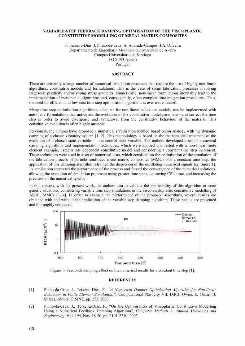
60
VARIABLE-STEP FEEDBACK DAMPING OPTIMISATION OF THE VISCOPLASTIC CONSTITUTIVE MODELLING OF METAL MATRIX COMPOSITES
F. Teixeira-Dias, J. Pinho-da-Cruz, A. Andrade-Campos, J.A. Oliveira Departamento de Engenharia Mecânica, Universidade de Aveiro
Campus Universitário de Santiago 3810-193 Aveiro
Portugal
ABSTRACT
There are presently a large number of numerical simulation processes that require the use of highly non-linear algorithms, constitutive models and formulations. This is the case of some fabrication processes involving largescale plasticity and/or strong stress gradients. Numerically, non-linear formulations inevitably lead to the implementation of incremental algorithms and, consequently, often complex time integration procedures. Thus, the need for efficient and low-cost time step optimisation algorithms is ever more needed.
Many time step optimisation algorithms, adequate for non-linear behaviour models, can be implemented with automatic formulations that anticipate the evolution of the constitutive model parameters and correct the time step in order to avoid divergence and withdrawal from the constitutive behaviour of the material. This constitutive evolution is often highly unstable.
Previously, the authors have proposed a numerical stabilisation method based on an analogy with the dynamic damping of a classic vibratory system [1, 2]. This methodology is based on the mathematical treatment of the evolution of a chosen state variable — the control state variable. The authors developed a set of numerical damping algorithms and implementation techniques, which were applied and tested with a non-linear finite element example, using a rate dependent constitutive model and considering a constant time step increment. These techniques were used in a set of numerical tests, which consisted on the optimisation of the simulation of the fabrication process of particle reinforced metal matrix composites (MMC). For a constant time step, the application of this damping algorithm refrained the dispersion of the oscillating numerical signals (cf. figure 1). Its application increased the performance of the process and forced the convergence of the numerical solutions, allowing the execution of simulation processes using greater time steps, i.e. saving CPU time, and increasing the precision of the numerical results.
In this context, with the present work, the authors aim to validate the applicability of this algorithm to more generic situations, considering variable time step simulations in the visco-elastoplastic constitutive modelling of AlSiCp MMCs [3, 4]. In order to evaluate the performance of the proposed algorithms, several results are obtained with and without the application of the variable-step damping algorithm. These results are presented and thoroughly compared.
Figure 1- Feedback damping effect on the numerical results for a constant time step [1].
REFERENCES
[1] Pinho-da-Cruz, J., Teixeira-Dias, F., “A Numerical Damper Optimisation Algorithm for Non-linear Behaviour in Finite Element Simulations”, Computational Plasticity VII, D.R.J. Owen, E. Oñate, B. Suárez, editors, CIMNE, pp. 253, 2003.
[2] Pinho-da-Cruz, J., Teixeira-Dias, F., “On the Optimisation of Viscoplastic Constitutive Modelling Using a Numerical Feedback Damping Algorithm”, Computer Methods in Applied Mechanics and Engineering, Vol. 194, Nos. 18-20, pp. 2191-2210, 2005.

61
[3] Teixeira-Dias, F., Menezes, L.F., “Numerical Aspects of Finite Element Simulations of Residual Stresses in Metal Matrix Composites”, International Journal for Numerical Methods in Engineering, Vol. 50, No. 3, pp. 629–644, 2001.
[4] Teixeira-Dias, F., Menezes, L.F., “Numerical Determination of the Influence of the Cooling Rate and Reinforcement Volume Fraction on the Levels of Residual Stresses in Al-SiC Composites”, Computational Materials Science, Vol. 21, No. 1, pp. 26–36, 2001.


63
SESSION 4 – FABRIC COMPOSITES
Chair: Prof. Stepan V. Lomov Katholieke Universiteit Leuven, Belgium
Monday 10th April 16:25 – 18:05

64
METHODOLOGY FOR CHARACTERIZATION OF INTERNAL STRUCTURE OF NCF COMPOSITE AND ITS INFLUENCE ON MECHANICAL PROPERTIES
Roberts Joffe and David Mattsson Div of Polymer Engineering, Luleå University of Technology, SE-971 87 Luleå, Sweden
ABSTRACT
Non-crimp fabric (NCF) composites due to their excellent performance and relatively low cost have become an attractive alternative for aerospace, marine and even automotive applications. One of the features of the NCF composite is that it is an inherently multiscale material. Each layer due to stitching is divided in fiber bundles. On the microscale each bundle with orientation φ is a UD composite with a certain fiber content Vφ
f and the homogenized bundle properties may be calculated using micromechanics expressions for long fiber composites. On the mesoscale the bundle is considered as homogeneous transversely isotropic material surrounded by matrix and other bundles of the same or different orientation. A mesoscale characteristic of the composite is bundle content Vφ
b in the composite. Combining (multiplying) these two volume contents, Vφf and Vφ
b , average content of fibers in laminate with certain orientation, Vφ
fa , can be obtained. Micrographs presented in Figure 1 demonstrate the hierarchical structure of the NCF composites.
Figure 1- Hierarchical structure of the NCF composites.
The geometrical shape of bundles (cross-section and axial alignment) is complex and depends on bundle orientation in the blanket, surface compression during production, resin pockets etc. The described mesoscale configuration determines the NCF composite properties on macroscale and is typically used in simulations of macro behaviour [1-4]. These studies demonstrated the importance of geometrical parameters of the micro/meso structure of the material on different mechanical properties of NCF composites. For instance, bundle waviness is a crucial parameter that defines compressive strength of composite laminates and it has also a strong influence on tensile strength and Young’s modulus of the composite. While cross-section characteristics and fiber content of bundles are required to analyze intrabundle cracks and delaminations. Significance of the different parameters for certain property can be graded with respect to its importance. Based on our previous studies on NCF composites such ranking is present in Table 1 where grade from 1 to 5 is given to different parameters of composite microstructure (number 5 refers to the highest significance).
Table 1- Influence of mesostructural parameters on different mechanical properties of the NCF composite.
Property Vφfa Vφ
b Vφf
Shape of the cross-section Waviness
Stiffness 5 1 1 1 5 Failure in Tension 1 3 3 3 5 Failure in Compression 2 3 3 1 5
Although the internal structure of the NCF composite directly affects their mechanical performance, there is no comprehensive study which describes and identifies all microstructural parameters in a structured way and gives methodology and practical recommendation on quantification of these parameters. Mesoscale structure of NCF composites is affected as much by processing of composites (impregnation of NCF with resin) as by geometry of the fabric itself. Therefore, in order to deal successfully with prediction of mechanical properties and failure events in NCF composites, final structure of the material has to be well known. This investigation is intended to identify and characterize critical parameters of internal structure of NCF composites which are important for

65
certain in-plane mechanical properties. This paper is focused on structural parameters and therefore it is not analysing the role of fiber and matrix properties which is, certainly, of great importance.
In this study classification and quantification of bundle shape and size as well as methodology for the measurements of fiber volume fractions (on different scales) and bundle waviness is introduced and applied to cross-ply and quasi-isotropic laminates.
The micrograph in Figure 2a shows waviness in quasi-isotropic laminate and quantitative representation of this waviness is shown in Figure 2b where bundles are represented by function of axial coordinate. Example of classification of bundles by shape of the cross-section is presented in Figure 3.
Figure 2- Bundle waviness: (a) micrograph of quasi-isotropic laminate and (b) quantitative representation of
waviness.
Figure 3- Classification of bundles by their shape.
A clear and consistent methodology is suggested to determine the identified basic parameters by optical microscopy investigation. Errors and artifacts introduced by abnormalities in internal structure and practical limitation of equipment are also considered. Proposed methodology is applied to cross-ply and quadriaxial NCF composites to demonstrate details and quantify characteristics of micro-structure dependent on the used manufacturing parameters. Parameters of internal structure of these laminates are compared between each other.
Approach and results presented in this paper demonstrate simple, yet useful method of reasonable accuracy to characterize structure of NCF composites. Due to its affordability in terms of equipment and time, this technique can be used not only by scientific community but also by manufacturers of NCF composite structures to monitor quality of their products.
REFERENCES
[1] Drapier S, Wisnom RM., “Finite element investigation of the compressive strength of non-crimp fabric based composites”, Composites Science and Technology, Vol. 59, pp.1287–97, 1999.
[2] Drapier S, Wisnom RM., “A finite-element investigation of the interlaminar shear behaviour of noncrimp-fabric-based composites”, Composites Science and Technology, Vol. 59, pp. 2351–62, 1999.
[3] Joffe R, Mattsson D, Modniks J, Varna J., “Compressive failure analysis of NCF composites with large out-of-plane misalignment of fiber bundles”, Composites Part A, Vol. 36, pp. 1030–46, 2005.
[4] Edgren F, Asp L., “Approximate analytical constitutive model for non-crimp fabric composites”, Composites: Part A, Vol. 36, pp. 173–181, 2005.

66
DETERMINATION OF STRENGTH PARAMETERS FOR NCF COMPOSITES
Fredrik Edgren and
Leif E. Asp SICOMP AB P O Box 104
SE-431 22 Mölndal Sweden
ABSTRACT
A method has been developed to characterise the strength parameters to a failure criterion for non-crimp fabric (NCF) composites by testing. The parameters are to be used in a criterion predicting failure of NCF laminates subjected to combined compression and shear loading. The criterion is a linear interaction between the compressive stress in the longitudinal fibre direction and the shear stress acting on the most highly loaded ply in the laminate.
The strength parameters input to the criterion are the uniaxial compressive strength and the pure shear strength when the mode of failure is fibre microbuckling (kinking). Since the fibres of NCF composites are not ideally straight, the material properties are affected accordingly. The material meso-structure (fibre waviness, fibre tow shape etc.) are affected by e.g. the composite manufacturing process, laminate stacking sequence and NCF preform configuration. Determination of the longitudinal compressive strength is thus not possible from tests on isolated UD laminates, as is commonly done with prepregs. Instead, the strength need to be measured in tests on the complete laminate.
Determination of the shear strength is even more complicated, since the mode of failure by definition (the criterion only predicts kinking failure) need to be fibre kinking. A standard shear test, e.g. Iosipescu shear test or a ±45°-tensile or -compressive test (in-plane shear), does not produce this mode of failure.
In the present study the strength parameters were determined from off-axis compression tests on a quasiisotropic (QI) laminate. Specimens were cut at five different off-axis angles (angle between specimen longitudinal loading direction and 0°-fibre direction); 0°, 5°, 10°, 15° and 20°. By performing compression tests of the laminate at different off-axis angles it was possible to vary the ratio compressive axial stress / shear stress in the specimens. When evaluating the ply material strength, it was assumed that the most highly loaded plies (the plies closest to 0°) controlled failure of the entire QI laminate. With the laminate failure strain from the tests and using conventional laminate theory (CLT) the stress state in the plies could be calculated at failure. The data extracted from the tests were plotted in a normal and shear stress diagram, as shown in Figure 1. Since the failure criterion predicts a linear interaction between compressive and shear stress, a linear fit to the off-axis test data was performed and extrapolated to the two stress axes. The crossing points of the extrapolated best fit with the axes in the diagram were chosen as the strength parameters (σL0 and τLT0 in Figure 1) to be used in the criterion for analysis of components and structures made from the particular composite system.

67
Figure 1- Ply strength data extracted from tests at different off-axis angles.
Post-mortem analyses of the failed specimens revealed that fibre kinking was the mode of failure for the tested specimens. In addition to the specimens loaded to failure, some specimens were interrupted prior to failure. Fractographic analyses of these specimens revealed that individual fibre tows had failed by kinking at loads lower (typically 90%) than the load at catastrophic failure.

68
EXPLORING MECHANICAL PROPERTY BALANCE IN TUFTED CARBON FABRIC/EPOXY COMPOSITES
Giuseppe Dell’Anno1*, Denis D Cartié1, Giuliano Allegri2, Ivana K Partridge1 and Amir Rezai3 1Polymer Composites Centre, School of Industrial and Manufacturing Science, Cranfield University, Cranfield,
Bedford, MK43 0AL, UK 2School of Engineering, Cranfield University, Cranfield, Bedford, MK43 0AL, UK
3BAE Systems, Advanced Technology Centre, Filton, Bristol BS34 7QW, UK
ABSTRACT
Background:
“Tufting” is essentially one-sided stitching (Figure 1) which avoids the addition of crimp onto the fibre architecture induced by standard stitching. The tufting stitch is never ‘locked’ and only remains in position because of frictional forces acting on it, leading to an almost tension-free structure. As such, tufting represents a very novel approach to localized through-the-thickness reinforcement in composite structures for the dry preform/liquid resin injection manufacturing route. A single needle takes a yarn through the fabric layers and returns back along the same trajectory, leaving a loop of the yarn on the back side of the plies (Figure 2).
The concept of tufting for dry fabrics is analogous to Z-pinning for prepregs: they both intend to reduce the problem of delamination by introducing along the Z axis of the laminate a medium capable of bridging the propagating interlaminar crack. Similarly to Z-pinned structures, the increased delamination resistance of the cured tufted composite can be expected to be accompanied by a reduction in the in-plane properties [1]. Although the dry fabric fibres are relatively free to move apart during the tufting, the penetrating action of the 2mm diameter metal hollow needle inevitably damages some filaments in the fabric yarns. In addition, the presence of the thread itself introduces
into the preform layers a certain degree of in-plane waviness which is expected to have an effect on the in-plane mechanical behaviour [2].
This work intends to draw some general baselines on the in-plane/out-of-plane properties balance in a Non-crimped Carbon Fabric/epoxy and in a 5 harness satin carbon fibre/epoxy composite reinforced by tufting in square 4mm×4mm and 3mm×3mm arrangement respectively with a Vetrotex Saint Gobain glass thread (EC9 68X3 S260 T8G H5). The crack bridging laws required for the analysis and modelling of the out-of-plane properties are defined by building and validating an analytical model of the mechanical behaviour of a single tuft within this composite.
Experimental:
The dry preforms were tufted using a commercially available tufting head interfaced to a 6 axis computer controlled robot arm (Figure 3). The reinforced woven fabric preform was resin injected by Resin Transfer Moulding technique using 1 bar pressure and cured at 180°C for 185 minutes whereas the tufted NCF preform was vacuum infused, cured at 80°C for 8 hours and post cured at 120°C for 5 hours.
Compression After Impact specimens were manufactured following the Boeing standard (BS 7260) and locally reinforced over a 50mmx50mm central area. After being impacted with energy of 15J, the ultimate compression strength was evaluated. The reinforcement resulted in a significant increase in the CAI value (Figure 4).
In addition to the standard coupons for the determination of the quasi-static mechanical properties, some cured single-tuft miniature specimens were also prepared (Figure 5). These are tested in both uniaxial pull-out and in a mode II
Figure 1- Top side of a tufted preform, with an enlargement in the
top LH corner.
Figure 2- Schematic of the yarn arrangement in a tufted preform.
Figure 3- Kawasaki FS 20N robot arm with a KSL KL150 tufting head.
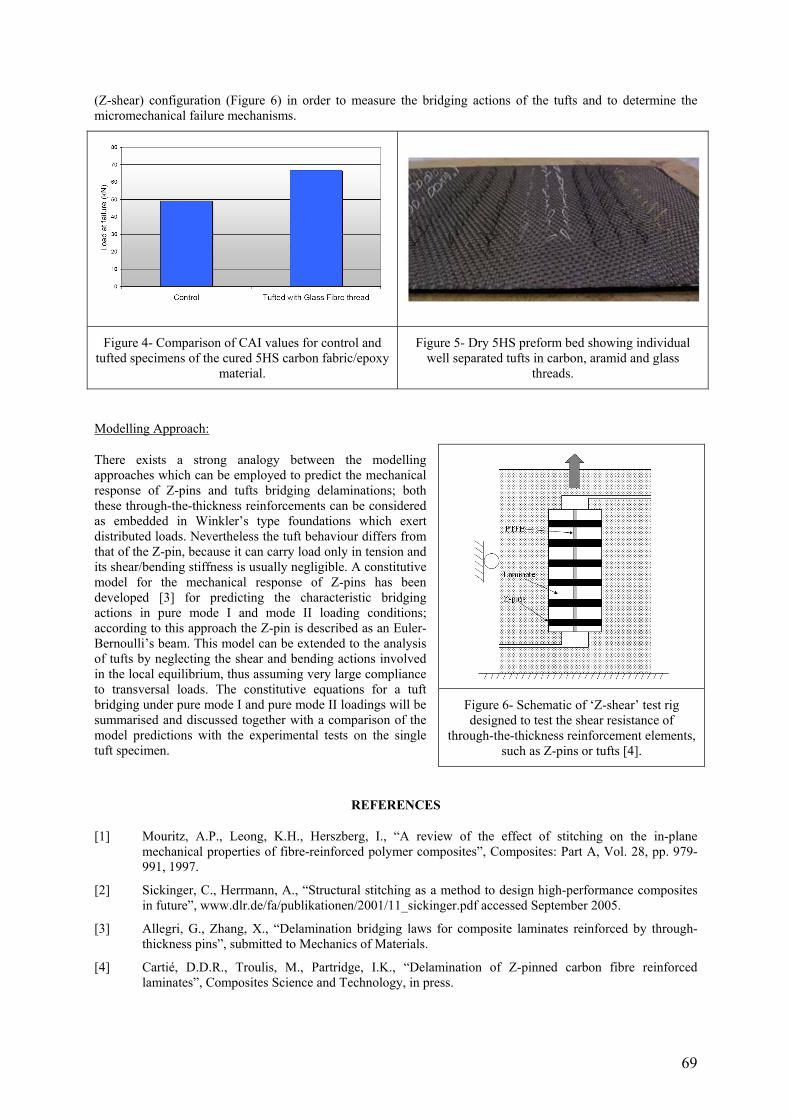
69
(Z-shear) configuration (Figure 6) in order to measure the bridging actions of the tufts and to determine the micromechanical failure mechanisms.
Figure 4- Comparison of CAI values for control and tufted specimens of the cured 5HS carbon fabric/epoxy
material.
Figure 5- Dry 5HS preform bed showing individual well separated tufts in carbon, aramid and glass
threads.
Modelling Approach:
There exists a strong analogy between the modelling approaches which can be employed to predict the mechanical response of Z-pins and tufts bridging delaminations; both these through-the-thickness reinforcements can be considered as embedded in Winkler’s type foundations which exert distributed loads. Nevertheless the tuft behaviour differs from that of the Z-pin, because it can carry load only in tension and its shear/bending stiffness is usually negligible. A constitutive model for the mechanical response of Z-pins has been developed [3] for predicting the characteristic bridging actions in pure mode I and mode II loading conditions; according to this approach the Z-pin is described as an Euler-Bernoulli’s beam. This model can be extended to the analysis of tufts by neglecting the shear and bending actions involved in the local equilibrium, thus assuming very large compliance to transversal loads. The constitutive equations for a tuft bridging under pure mode I and pure mode II loadings will be summarised and discussed together with a comparison of the model predictions with the experimental tests on the single tuft specimen.
REFERENCES
[1] Mouritz, A.P., Leong, K.H., Herszberg, I., “A review of the effect of stitching on the in-plane mechanical properties of fibre-reinforced polymer composites”, Composites: Part A, Vol. 28, pp. 979-991, 1997.
[2] Sickinger, C., Herrmann, A., “Structural stitching as a method to design high-performance composites in future”, www.dlr.de/fa/publikationen/2001/11_sickinger.pdf accessed September 2005.
[3] Allegri, G., Zhang, X., “Delamination bridging laws for composite laminates reinforced by through-thickness pins”, submitted to Mechanics of Materials.
[4] Cartié, D.D.R., Troulis, M., Partridge, I.K., “Delamination of Z-pinned carbon fibre reinforced laminates”, Composites Science and Technology, in press.
Figure 6- Schematic of ‘Z-shear’ test rig designed to test the shear resistance of
through-the-thickness reinforcement elements, such as Z-pins or tufts [4].

70
EXPERIMENTAL EVALUATION AND CONSIDERATION OF NUMERICAL METHOD OF ZANCHOR CFRP LAMINATES
Yuichiro Aoki, Yosuke Nagao, Takashi Ishikawa Advanced Composite Technology Center,
Japan Aerospace Exploration Agency Japan
Fumihito Takeda
Engineering Research Department, Mitsubishi Heavy Industries, LTD
Japan
ABSTRACT
Improving interlaminar fracture toughness is a major concern for reducing the strength risk of composite structures. The technology called “Zanchor” was developed by Mitsubishi Heavy Industries, Ltd. and Shikibo Ltd as a solution for this risk [1]. That is a unique technology for through-thickness reinforcement. Laminated dry fabrics are stuck by a special needle and in-plane carbon fibers are entangled to other layers shown as Figure 1(a). After the needling, the dry fabric is infused and cured by resin film infusion or resin transfer molding. Figure 1 (b) is a cross-sectional observation of the needling point of a quasi-isotropic Zanchor CFRP laminate. It can be found that the fibers in 0-degree layer are entangled to the adjacent 45-degree layers by the needling. This Zanchor process makes through-thickness reinforcement of entangled in-plane fibers. Intensity of reinforcement can be adjusted by the number of needling, i.e. Zanchor density. The Zanchor CFRP laminates of different Zanchor densities are prepared Z=0, 1, 2, 4 for every type of test specimens. Z=0 is non-Zanchor as a control. Z=1 is a baseline of the Zanchor density and increasing number means proportional increasing of needling number compared with Z=1. For example, the specimen of Z=2 has two times Zanchor density of Z=1 specimen.
First, DCB tests for the CFRP specimen of different Zanchor densities were carried out. Mode I energy release rates (GIR) were calculated from load-COD (Crack Opening Displacement) curves and crack lengths by using area method. Figure 2 shows load-COD curves and crack propagation curves for different Zanchor densities. In this figure, the maximum load of Z=4 is 2.5 times as higher as Z=0. The load-COD curves are also shifted upward in accordance with Zanchor density. Furthermore, delamination propagation rate became slower with Zanchor density increases. The GIR is averaged value for each Zanchor density. The GIR of Z=4 is over 3 times larger than Z=0.
Figure 3 shows some of the major experimental results of tensile, compression, OHC, CAI tests. It was found that the technology provides significant reductions of impact damage area and increasing CAI strength. There is, however, degradation in in-plane mechanical properties caused by needling itself. Therefore, the mechanism of interlaminar reinforcement and in-plane degradation due to Zanchor must be well understood to utilize the novel technology.
In this study, a numerical method is developed to evaluate the Zanchor CFRP laminates. The analytical model with different Zanchor densities is first applied to simple tension tests, and then to the DCB tests. The analysis results are compared to the experimental results.
Figure 1- Overview of Zanchor technology: (a)
schematic view of the Zanchor process, (b) Crosssectional observation of the needling point of
a quasi-isotropic Zanchor CFRP laminate. Figure 2- Load-COD curves and crack length.
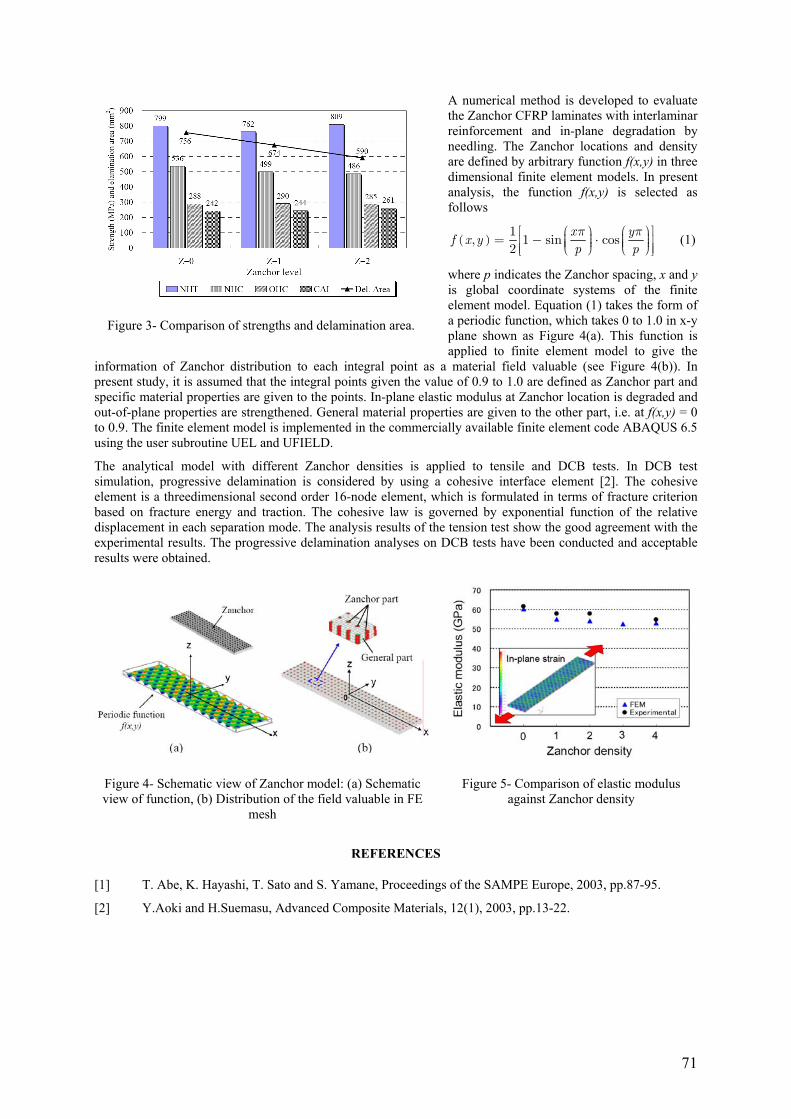
71
A numerical method is developed to evaluate the Zanchor CFRP laminates with interlaminar reinforcement and in-plane degradation by needling. The Zanchor locations and density are defined by arbitrary function f(x,y) in three dimensional finite element models. In present analysis, the function f(x,y) is selected as follows
( )1
, 1 sin cos2
x yf x y
p pπ π⎡ ⎛ ⎞ ⎛ ⎞⎤⎟ ⎟⎜ ⎜= − ⋅⎢ ⎥⎟ ⎟⎜ ⎜⎟ ⎟⎜ ⎜⎝ ⎠ ⎝ ⎠⎢ ⎥⎣ ⎦
(1)
where p indicates the Zanchor spacing, x and y is global coordinate systems of the finite element model. Equation (1) takes the form of a periodic function, which takes 0 to 1.0 in x-y plane shown as Figure 4(a). This function is applied to finite element model to give the
information of Zanchor distribution to each integral point as a material field valuable (see Figure 4(b)). In present study, it is assumed that the integral points given the value of 0.9 to 1.0 are defined as Zanchor part and specific material properties are given to the points. In-plane elastic modulus at Zanchor location is degraded and out-of-plane properties are strengthened. General material properties are given to the other part, i.e. at f(x,y) = 0 to 0.9. The finite element model is implemented in the commercially available finite element code ABAQUS 6.5 using the user subroutine UEL and UFIELD.
The analytical model with different Zanchor densities is applied to tensile and DCB tests. In DCB test simulation, progressive delamination is considered by using a cohesive interface element [2]. The cohesive element is a threedimensional second order 16-node element, which is formulated in terms of fracture criterion based on fracture energy and traction. The cohesive law is governed by exponential function of the relative displacement in each separation mode. The analysis results of the tension test show the good agreement with the experimental results. The progressive delamination analyses on DCB tests have been conducted and acceptable results were obtained.
Figure 4- Schematic view of Zanchor model: (a) Schematic view of function, (b) Distribution of the field valuable in FE
mesh
Figure 5- Comparison of elastic modulus against Zanchor density
REFERENCES
[1] T. Abe, K. Hayashi, T. Sato and S. Yamane, Proceedings of the SAMPE Europe, 2003, pp.87-95.
[2] Y.Aoki and H.Suemasu, Advanced Composite Materials, 12(1), 2003, pp.13-22.
Figure 3- Comparison of strengths and delamination area.


73
SESSION 5 – FATIGUE AND DURABILITY
Chair: Prof. Manuel de Freitas Technical University of Lisbon, Portugal
Tuesday 11th April 08:30 – 10:35
74
DELAMINATION RESEARCH: PROGRESS IN THE LAST TWO DECADES AND THE CHALLENGES AHEAD
Paul Robinson Department of Aeronautics, Imperial College London, United Kingdom
ABSTRACT
Delamination has long been recognised as a significant weakness of fibre reinforced, polymer matrix laminated composites – indeed it is often referred to as the Achilles Heel of what, in many other respects, can be justifiably termed high performance structural materials. This weakness initiated a considerable research activity which has addressed a range of aspects associated with this problem. This paper will summarise the progress of this research over the past two decades and identify some of the remaining challenges.
The development of test methods to characterise the resistance to delamination has seen considerable progress. Research has focussed primarily on test methods for determining the critical energy release rates in Modes I, II and mixed mode I/II, with a smaller effort directed to Mode III. The double cantilever beam test devised for Mode I has achieved national and international standard status but, perhaps surprisingly, no single accepted test has been developed for Mode II.
The ability to reliably measure the interlaminar toughness, at least in Mode I, and therefore rank competing materials has lead to the development of composites with improved delamination resistance. These materials developments have not simply concerned improvements of the matrix; the addition of reinforcement through the thickness of a laminate has also been investigated in a variety of forms including ‘2.5D’ fabrics, stitching, z-fibres, and tufting. These additions can considerably improve the resistance to delamination growth but this improvement is often at the expense of other mechanical properties – particularly the in-plane compression strength. (The development of such materials has also had a consequence for research into interlaminar test methods. These through-thickness reinforced materials can exhibit large fibre-bridged zones in the wake of the delamination front and this can invalidate existing test procedures).
Research has also been conducted to develop analysis methods to model the growth of delamination so that engineers can assess the susceptibility to, and consequences, of delamination during the design of laminated composite structures. Some simple formulae exist for particular situations but to properly represent the complexity of practical structures it is necessary to use finite element (FE) analysis. Early FE-based approaches focussed on the evaluation of energy release rate (most commonly by the virtual crack closure method but others have also been proposed). This energy release rate could then be compared to the critical values measured in tests to decide whether the delamination under investigation would grow. Strategies for automatically advancing the crack front within the FE model were also proposed but for practical structures, in which, for example, delaminations might grow under stiffeners, very complex re-meshing strategies are required. An alternative which can avoid these remeshing difficulties is the use of ‘cohesive zone’ or ‘interface’ elements which have been developed more recently. These elements are incorporated in the FE model at interfaces between plies and have a constitutive law which ensures the correct amount of energy is absorbed as the adjacent plies separate. This approach has become widely adopted and is available in a number of commercial FE packages.
Despite the considerable research that has been performed it is clear that there is still some way to go before all the tools to address the problem of delamination can be considered routine. The methods to fully characterise the interlaminar toughness are not yet available. As noted above an international standard for Mode II testing is yet to be established and to date these interlaminar test methods have nearly exclusively examined unidirectional materials with the fibre reinforcement lying in the crack growth direction, although there have been a number of research papers attempting to drive this issue. The modelling tools and choice of interface element laws still need further development – it is clear that for some situations there is a wide choice of form of the interface constitutive law and this needs to be fully resolved. Real delamination growth often progresses with migration.

75
LONG-TERM AGING AND DURABILITY OF HIGH TEMPERATURE POLYMER COMPOSITES
G. A. Schoeppner1, K.V. Pochiraju2, and G. P. Tandon3 1Air Force Research Laboratory, Wright Patterson AFB, OH, USA
2Steven’s Institute of Technology, Hoboken, NJ, USA 3University of Dayton Research Institute, Dayton, OH, USA
ABSTRACT
Durability and degradation mechanisms in composites are fundamentally influenced by the fiber, matrix, and interphase regions that constitute the composite domain. The thermo-oxidative behavior of the composite is significantly different from that of the fiber and matrix constituents as the composite microstructure, including the fiber-matrix interphases/interfaces, introduces anisotropy in the diffusion behavior. In this work, neat resin PMR-15 high temperature resin and unidirectional G30-500/PMR-15 composite specimens were aged at elevated temperatures. PMR-15 has been used in the aeronautical industry for over 20 years due to its high glass transition temperature and thermo-oxidative stability [1]. It is well known that the free surfaces of high-temperature Polymer Matrix Composites (PMCs) are susceptible to oxidation that leads to the development of surface and ply cracking and accelerated degradation when in the presence of thermo-mechanical loading. Once ply cracking has initiated, new free surfaces are introduced into the composite providing pathways for oxidants that inevitably lead to degradation of the fiber matrix interfaces, reducing the lifetime and durability of these material systems [2]. Therefore, it is essential to fully characterize these high-temperature composites on a constituent level so that their physical and chemical responses from the oxidation process are fully understood.
A primary measure of the thermal oxidative stability of PMR-15 and other high temperature composite materials is the percentage weight loss as a function of isothermal aging time and temperature. In general, the relationship between weight loss and property changes can be highly nonlinear and does not provide any measure of the spatial variability of degradation within the specimen. The reliability of predictive methods based on weight loss in which small changes in weight can result in significant declines in mechanical properties, is highly questionable. However, in the absence of methods to predict end of life properties, weight loss is an accepted screening tool to compare the thermal oxidative stability (TOS) of different materials. To accurately predict the performance of polymer matrix composite (PMC) components and structures subjected to thermo-mechanical loading, knowledge of the individual aging mechanisms, their synergistic effects, and the spatial variability of the thermo-oxidative degradation is critical. The findings of the present investigation along with the results of ongoing work to characterize the influence of the fiber-matrix interface on thermal oxidation will provide the necessary basis for predicting the thermo-oxidative micromechanical response of PMR-15 laminates [3].
In this work, unidirectional G30-500/PMR-15 composite specimens were aged at elevated temperatures in air resulting in oxidation propagation parallel and perpendicular to the fibers. Four different specimen geometries were chosen such that different surface area ratios (i.e., ratios of surface area perpendicular to the fibers to surface area parallel to the fibers) were obtained. Weight loss and volumetric changes were monitored as a function of aging time to study the high temperature anisotropic oxidation process. A new weight loss model has been developed. Optical micrographs were taken on polished internal sections and viewed in the dark-field mode to measure the degree, depth and distribution of thermal oxidation development from external surfaces perpendicular and parallel to the fibers as shown in Figure 1. Additionally in this work, thermo-oxidative aging is simulated with a diffusion/reaction model in which temperature, oxygen concentration and weight loss effects are considered [4, 5]. A parametric reaction model based on a mechanistic view of the reaction is used for simulating reaction rate dependence on the oxygen availability in the polymer. Macroscopic weight-loss measurements are used to determine the reaction and polymer consumption parameters. As a first approximation, it is assumed that the transport of oxygen within the polymer is controlled by Fickian diffusion. The oxygen reacts with the polymer followed by degradation of the material. With C(x,y,z;t) denoting the concentration field at any time within a domain with a diffusivity of Dij and consumptive reaction with a rate R(C), the diffusion reaction with orthotropic diffusivity is given by Eq. (1)
( )2 2 2
11 22 332 2 2C C C CD D D R Ct x y z
⎛ ⎞∂ ∂ ∂ ∂ ⎟⎜= + + −⎟⎜ ⎟⎟⎜∂ ⎝ ⎠∂ ∂ ∂ (1)
subjected to the boundary conditions: C = Cs on the exposed boundaries and dC/dt = 0 on symmetry boundaries. The boundary sorption on the exposed boundaries is given by Henry’s equation
SC SP= (2)
where S is the solubility and P is the partial pressure of the oxygen in the environment. The diffusivities are temperature dependent typically given in Arrhenius form:

76
( )0 0exp /ijD D E RT= − (3)
and determined using permeability tests at lower temperatures to determine the pre-exponent (D0) and the activation energy parameters (Ea). The reaction rate term, R(C), is modeled with the Arrhenius-type kinetics model [6,7] for capturing the temperature dependence of the reaction rates or using mechanistic reaction models such as Abdeljaoued [8] for capturing the oxygen concentration dependence.
REFERENCES
[1] Meadors, M.A., Lowell, C.E., Cavano, P.J., and Herrera-Fierro, P.,”On the Oxidative Degradation of Nadic Endcapped Polyimides: I. Effect of Thermocycling on Weight Loss and Crack Formation”, High Performance Polymers, 8 (1996) 363-379.
[2] Bowles, K.J. and Meyers A.,”Specimen Geometry Effects on Graphite/PMR-15 Composites During Thermo-Oxidative Aging”, Proceedings 31st International SAMPE Symposium, Anaheim, CA, 1986.
[3] Pochiraju K.V. and G. P. Tandon, G.P.,“Modeling Thermo-Oxidative Layer Growth in High Temperature Resins”, accepted for publication in Journal of Engineering Materials and Technology.
[4] Tandon, G.P., Pochiraju, K., and Schoeppner, G.A.,“Modeling of Oxidative Development in PMR-15 Resin”, Presented at the SAMPE 2005 Symposium & Exhibition Long Beach, California, May 1-5, 2005.
[5] Colin, X., Marais, C. and Verdu, J. (2001), “Thermal Oxidation Kinetics for a Poly(bismaleimide)”, Journal of Applied Polymer Science, Vol. 82, pp. 3418-3430.
[6] Cunningham, R. A., “High Temperature Degradation Mechnaisms in Polymer Matrix Composites”, Master’s Thesis, Massachusetts Institute of Technology, 1996.
[7] McManus, H. L., Foch, B. J., and Cunningham, R. A., “Mechanism-Based Modeling of Long-Term Degradation”, Journal of Composites Technology and Research, Vol. 22, No. 3, pp. 146-152, 2000.
[8] Abdeljaoued, K., Thesis, “Thermal Oxidation of PMR-15 Polymer Used as a Matrix in Composite Materials Reinforced with Carbon Fibers”, Ecole Nationale Superieure des Arts et Metiers, Paris, 1999.
Figure 1- Oxidation of unidirectional G30-500/PMR-15 composites at 288ºC.

77
NONLINEAR CONSTANT FATIGUE LIFE DIAGRAMS FOR CFRP LAMINATES
M. Kawai and M. Koizumi Department of Engineering Mechanics and Energy,
Graduate School of Systems and Information Engineering, University of Tsukuba, Tsukuba 305-8573, Japan.
INTRODUCTION
For prediction of the fatigue lives of composite materials and structures subjected to various modes of loading that is characterized by variable amplitude, mean, frequency and waveform, it is essential to establish an engineering method of calculating S-N curves at any stress ratio [1-4]. The effect of stress ratio on fatigue strength can be described using a constant fatigue life (CFL) diagram. Harris et al. [1] examined the constant fatigue life diagrams for CFRP laminates for various stress ratios and showed that the CFL envelopes are asymmetric and the peak positions are slightly offset to the right of the stress amplitude axis. Ansell et al. [2] suggested that the maxima of the CFL envelopes appear at a stress ratio almost equal to the C/T strength ratio, i.e. the ratio of compressive strength to tensile one.
The present study focuses on exploration of the shape of constant fatigue life diagrams for different constant values of fatigue life of CFRP laminates. First, the stress ratio effects are observed for a quasi-isotropic [45/90/-45/0]2s CFRP laminate. Then, a new methodology to construct a nonlinear constant fatigue life (CFL) diagram is developed on the basis of the static strengths in tension and compression and the reference S-N relationship for the stress ratio equal to the C/T strength ratio. Validity of the proposed fatigue life rediction method is evaluated also for the fatigue behavior of different types of CFRP laminates at various stress ratios.
TEST PROCEDURE
Symmetrical quasi-isotropic carbon/epoxy laminates with a [45/90/-45/0]2S lay-up were manufactured by the autoclave forming technique. The prepreg tape made of carbon fibers T800H (TORAY) and thermosetting epoxy resin #3631 is used. Constant amplitude fatigue tests on coupon specimens in one of the principal directions were performed at different stress ratios R = 0.5, 0.1, χ, -1.0, 10, 2, respectively. The value of χ is equal to the C/T strength ratio. Fatigue load was applied in a sinusoidal waveform with a frequency of 10 Hz at room temperature. Most specimens were fatigue tested for up to 106 cycles, and fatigue tests that lasted over this limit were terminated prior to fracture.
EXPERIMENTAL RESULTS
The fatigue data on the [45/90/-45/0]2S CFRP laminate at stress ratios of R = 0.1, 0.5, -0.681 are shown in Figure 1, as a typical plot of the maximum fatigue stress σmax against the logarithm of the number of reversals to failure log 2Nf. It is clearly observed that the fatigue data at a larger stress ratio tend to be shifted rightward from those for R = -0.681 and the slope of the S-N curve becomes gentler. Figure 2 shows the S-N relationships for fatigue loading at R = -1, 2, 10. The reduction in fatigue strength for R = -1 is more significant than that under C-C loading. The difference between the S-N curves for R = 2, 10 was insignificant.
The CFL data on the [45/90/-45/0]2S CFRP laminate for different constant values of life Nf = 103, 104, 105 and 106 are plotted in Figure 3. The maximum fatigue stresses that correspond to the constant values of life were evaluated by curve fitting to the S-N relationships. It is clearly observed that the CFL plots are asymmetric. The peak of the CFL envelope is slightly offset to the right of the alternating stress axis. These plots indicate that the alternating stress becomes maximum at a stress ratio closely equal to the C/T strength ratio, i.e. R = -0.681. This observation is consistent with earlier observation by Ansell et al. [2].
DISSIMILAR CFL DIAGRAMS MODELING
In this study, it has been found that the CFL envelopes for different constant values of life are linear in the range of a short life but they turn quadratic in the range of a longer life. Such a dissimilar shape of asymmetric CFL envelope can be described by means of the following two functions:
2
a a m m
a T m
χψχ χ
χ χσ σ σ σ
σ σ σ
−− ⎛ − ⎞⎟⎜− = ⎟⎜ ⎟⎜⎝ ⎠− (1)

78
Figure 1- The S-N relationships for R = 0.5, 0.1, -0.681. Figure 3- Constant fatigue life diagrams.
Figure 2- The S-N relationships for R = 2, 10, -1.0. Figure 4- Predicted S-N relationships.
for the range of stress ratio 1Rχ ≤ ≤ , and
2
a a m m
a C m
χψχ χ
χ χσ σ σ σ
σ σ σ
−− ⎛ − ⎞⎟⎜− = ⎟⎜ ⎟⎜⎝ ⎠− (2)
for R χ≤ , 1R > , where σT and σC denote tensile and compressive strengths, and aχσ and m
χσ represent the stress amplitude and mean stress for fatigue loading at the critical stress ratio χ , respectively. The variable ψχ is a normalized fatigue stress level for the critical stress ratio χ. Dashed curves in Figure 3 are the predictions using this method. Note that the construction of the dissimilar CFL envelopes is based on only the static strengths in tension and compression and the reference S-N curve at the critical stress ratio χ.
Comparison between the predicted and observed S-N relationships is presented in Figure 4 for the stress ratios of R = 0.1, 0.5. The fatigue behavior of the quasi-isotropic CFRP laminate and its R-dependence have favorably been described using the proposed dissimilar CFL diagram model. It is demonstrated that the proposed fatigue life prediction method can successfully be applied also to different types of CFRP laminates: [0/±60]2s and [0/90]3s.
REFERENCES
[1] Harris, B., Reiter, H., Adam, T., Dickson, R.F., Fernando, G., “Fatigue behaviour of carbon fibre reinforced plastics”, Composites, Vol. 21, No. 3, pp. 232-242, 1990.
[2] Ansell, M.P., Bond, I.P., Bonfield, P.W., “Constant Life Diagrams for Wood Composites and Polymer Matrix Composites”, In: Proc. 9th Int. National Conf. on Composite Materials (ICCM 9), Madrid, Vol. V, pp. 692-699, 1993.
[3] Adam, T., Fernando, G., Dickson, R.F., Reiter, H., Harris, B., “Fatigue life prediction for hybrid composites”, International Journal of Fatigue, Vol. 11, No. 4, pp. 233-237, 1989.
[4] Kawai M. “A phenomenological model for off-axis fatigue behavior of unidirectional polymer matrix composites under different stress ratios”, Composites Part A, Vol. 35, No. 7-8, pp. 955-963, 2004.

79
FIBRE-MATRIX DEBONDING IN TRANSVERSE CYCLIC LOADING OF UNIDIRECTIONAL COMPOSITE PLIES
E. Correa*, E. K. Gamstedt** and F. París* *Grupo de Elasticidad y Resistencia de Materiales, Escuela Superior de Ingenieros, Universidad de Sevilla, Camino de los Descubrimientos s/n, E-41092 Sevilla, Spain
**KTH Solid Mechanics, Osquars backe 1, SE-100 44 Stockholm, Sweden E-mail: [email protected], [email protected], [email protected]
ABSTRACT
Fatigue of composite materials is of great concern in load-carrying structures. In fact, most failures of composite structures can be attributed to fatigue. Due to the heterogeneity of composite materials at different scales, a large variety of interacting mechanisms contribute to fatigue failure. If the incipient mechanisms at the onset of damage accumulation could be better understood, bases for a physically based fatigue law may be built and measures could be taken in order to extend the lifetime of the material.
Figure 1- Drawing of the formation of debonds and subsequent link-up and transverse cracking (under uniaxial
transverse horizontal loading in the figure).
The first observable type of damage in fatigue of composite laminates is generally transverse cracking in plies with oblique fibre orientation to the direction of the largest principal ply strain. Microscopic investigations have shown that the transverse cracks are initiated from coalescence of fibre-matrix debonds, both in static and cyclic loading [1]. A schematic illustration is shown in Figure 1. In paralell, several numerical studies have also been developed [2, 3], aiming to clarify the particular case of static transversal tension loads in unidirectional composites, leading to the conclusion that this micromechanism of failure can be explained by the appearance of cracks in the interfaces between the fibres and the matrix that, after growing to a certain extension along the interfaces, change their direction of propagation, kink into the matrix and continue their growth through it. The coalescence between them then takes place, leading to the macro failure of the composite in the direction perpendicular to the load.
Focusing on fatigue loading, a relevant aspect is that, for composite materials, tension-compression fatigue has shown to be more deleterious than tension-tension fatigue. The physical reason for the adverse effect of tensioncompression loading at ply level has not been clarified entirely and remains even more unclear at micromechanical level. Details of the detrimental effects of compressive load excursions, for the particular case of pure unidirectional transverse composites, can be found in [4, 5].
Based on the evidence mentioned above, the present work focuses on the propagation of interface cracks, in order to study, by means of a single fibre model, the micromechanical growth of an interface crack in presence of both, tension-tension and tension-compression fatigue. The main objective is to analyze, at micromechanical level, the origin of the more damaging effect of T-C than T-T cycles. In order to achieve this, experimental and numerical studies have been developed.
The experimental study, consisting in a single-fibre composite test, has shown, at micromechanical level, how the debonding angle of the interface crack evolves versus both T-C and T-T cycles, having been able to detect, at this level, the more deleterious effect of T-C fatigue than T-T fatigue. A summary of the results obtained is presented in Figure 2.

80
Figure 2- Results of the evolution of the debonding angle versus the number of cycles in the single-fibre
composite test.
The numerical study, consisting on a single-fibre BEM model, has made possible to analyze separately the influence of the different parts of the loading cycles (tension and compression) over the interface crack propagation. The results of this analysis, in terms of the Energy Release Rate (ERR), Figure 3, give an explanation of the more damaging effect of T-C than T-T cycles, previously observed with the experimental test. This micromechanical explanation is based in the different character of ERR for tension and compression and the rising character of GI in compression, for the debonding range of interest, as well as the smaller value of GIc versus GIIc.
Thus, the results obtained prove, at micromechanical level, the negative influence on compressive excursions in fatigue loading and show the relevant possibilities that micromechanical studies (experimental and numerical) have to help in the understanding of the mechanisms of failure of composite materials.
Figure 3- Energy release rate with mode I and II contributions with a far-field stress of 1 Pa in (a) tension and (b)
compression.
REFERENCES
[1] Gamstedt, E.K. and Sjögren, B.A., “Micromechanisms in Tension-Compression Fatigue of Composite Laminates containing Transverse Plies”, Composites Science and Technology , Vol. 59, 167-178, 1999.
[2] París, F., Correa, E. and Cañas, J., “Micromechanical view of failure of the matrix in fibrous composite materials”, Composites Science and Technology, Vol. 63, 1041-1052, 2003.
[3] París, F., Correa, E. and Mantič, V., “Kinking of transversal interface cracks between fibre and matrix”, Journal of Applied Mechanics., submitted for publication.
[4] Rotem, A. and Nelson, H.G., ”Failure of a laminated composite under tension-compression fatigue loading”, Composites Science and Technology ,Vol. 36, 45-62, 1989.
[5] El Kadi, H. and Ellyin, F., ”Effect of Stress Ratio on the Fatigue of Unidirectional Glass Fibre/Epoxy Composite Laminae”, Composites, Vol. 25, 917-924, 1994.

81
POSTER SESSION 3
Tuesday 11th April 10:35 – 11:15

82
A MICROMECHANICAL MODELLING FOR PREDICTION OF BEHAVIOR AND DAMAGE OF POLYDISPERSE SYNTACTIC FOAMS
Rim Zouari, Abedelwahed Ben Hamida, Hélène Dumontet Laboratoire de Modélisation, Matériaux et Structures, Institut de Mécanique
Université Pierre et Marie Curie, Paris, France
ABSTRACT
Syntactic foam is a composite material with hollow glass microspheres embedded in a polymeric matrix. These materials are known to possess low density, high buoyancy and strength at high pressures. Moreover, their thermal efficiency and water insulation properties make them attractive for offshore applications in deep sea.
Several micromechanical modelling have been used to study the behavior of these heterogenous materials. So for example Huang & al. [3] have applied analytical homogenization model for predicting the effective mechanical properties of syntactic foams. More recently Bardella et al. [1] have proposed a simplified homogenization method based on the works of Hervé et al. [2]. Benhamida et al. [7] have used the periodic homogenization method to predict the behavior and the failure under combined stress states of syntactic foams. Contrary to explicit methods, the periodic method is not limited to composites with low rates of filling and gives an accurate description of the local fields. In return it requires simulations on a basic cell and then is limited to consider all microspheres with the same size or as much as possible to two different sizes.
The objective of this paper is to propose a homogenization method which can take into account the dispersion of the size of the microspheres and gives access to accurate local stresses for the prediction of the damage. An iterative process which can be coupled to various simplified homogenization methods has been previously proposed by Benhamida et al [6]. This process consists to construct the composite in introducing the heterogeneities progressively into the matrix. Thus, to reach the given medium with a known volume fraction of heterogeneities, a number of intermediate states of composite must be created. For a given step, the effective constitutive law of those intermediate composite is obtained by any homogenization method. All homogenization methods, the dilute strain and stress approximations, the Hashin’s bounds, the periodic media method, the differential effective method or for example the N-layered inclusions method, coincide after convergence of the iterative process. Moreover this convergence of homogenization methods is obtained whatever the volume fraction of heterogeneities, even for significant fractions. The method brings too a correction of micro structural stresses and failure criterion based upon these more accurate stresses delivers a better forecast for the onset of material ruin. This process has been applied successfully by Brini et al. [5] to the study of the damage by the wet ageing of glass. With a population of identical microspheres, a rough estimate of the material lifetime has been obtained under the influence of glass chemistry.
In this paper, we extend these previous works by introducing into the iterative process the realistic dispersion of the size of the hollow microspheres. The effective behavior of polydisperse foams is thus estimated and shows the contribution of the various sizes of the microspheres by comparison to the behavior obtained with identical microspheres. The study of the local stresses coupled to failure criterion shows the fragility of the thin microspheres under pression. By this approach it is possible to follow the successive damage of the foam. Each damaged microsphere can be then suppressed and the process repeated in order to study the evolution of the damage.
So Figure 1 shows the importance on the behavior of polydisperse modelling by comparison to monodisperse equivalent modelling, the thickness of all microspheres being equal to the average of the different thicknesses. The results are validated by comparison with results of periodic method in the case of two families of microspheres. Comparisons with other modelling, Bardella et al. [1], Huang et al. [3] and experimental data, Dan [4] are too carried out. The evolution of the radial microstresses at the interface between the matrix and the different microspheres compared to the Timoshenko’s buckling criterion shows at Figure 2 that the finest micropshere with ratio thickness/diameter equal to 0.01 is damaged and the microsphere with ratio thickness/diameter equal to 0.02 is only damaged for strongly reinforced composite.
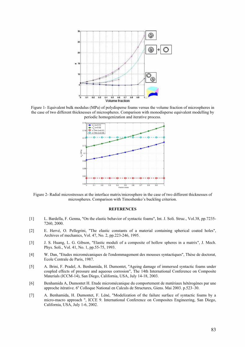
83
Figure 1- Equivalent bulk modulus (MPa) of polydisperse foams versus the volume fraction of microspheres in the case of two different thicknesses of microspheres. Comparison with monodisperse equivalent modelling by
periodic homogenization and iterative process.
Figure 2- Radial microstresses at the interface matrix/microsphere in the case of two different thicknesses of
microspheres. Comparison with Timoshenko’s buckling criterion.
REFERENCES
[1] L. Bardella, F. Genna, "On the elastic behavior of syntactic foams", Int. J. Soli. Struc., Vol.38, pp.7235-7260, 2000.
[2] E. Hervé, O. Pellegrini, "The elastic constants of a material containing spherical coated holes", Archives of mechanics, Vol. 47, No. 2, pp.223-246, 1995.
[3] J. S. Huang, L. G. Gibson, "Elastic moduli of a composite of hollow spheres in a matrix", J. Mech. Phys. Soli., Vol. 41, No. 1, pp.55-75, 1993.
[4] W. Dan, "Etudes micromécaniques de l'endommagement des mousses syntactiques", Thèse de doctorat, Ecole Centrale de Paris, 1987.
[5] A. Brini, F. Pradel, A. Benhamida, H. Dumontet, "Ageing damage of immersed syntactic foams under coupled effects of pressure and aqueous corrosion", The 14th International Conference on Composite Materials (ICCM-14), San Diego, California, USA, July 14-18, 2003.
[6] Benhamida A, Dumontet H. Etude micromécanique du comportement de matériaux hétérogènes par une approche itérative. 6e Colloque National en Calculs de Structures, Giens. Mai 2003. p.523–30.
[7] A. Benhamida, H. Dumontet, F. Léné, "Modelization of the failure surface of syntactic foams by a micro-macro approach ", ICCE 9. International Conference on Composites Engineering, San Diego, California, USA, July 1-6, 2002.

84
ASSESSING FATIGUE DAMAGE IN GRP COMPONENTS USING INFRA RED TECHNIQUES
J. M. Dulieu-Barton, T. R. Emery, P.R. Cunningham Fluid Structures Interaction Group
School of Engineering Sciences University of Southampton
Southampton, UK
ABSTRACT
Full-field data captured equating to the real-time stress state in a composite material has the ability to provide useful information to understand stress redistribution due to damage. One process that offers this capability is Thermoelastic Stress Analysis (TSA) [1]. The process has been used to investigate damage in composite materials by calculating a ratio of the stress states recorded from data sets from damaged and undamaged specimens [2 - 5]. Predominantly the specimens used in these tests are fatigued at purposefully low load levels.
Fatigue tests at realistic loading levels introduce a challenge in analysing TSA data, this is due to an expected change in the absolute temperature of the specimen under observation. Temperature increases are recognised in laminated composite materials due to internal heat generation during cyclic loading [6]. The rise in the absolute temperature of the specimen under observation increases the theromelastic response [5, 7]. The increase in response due to temperature rise instead of stress change is significant because of the inherent characteristics of the infra-red photon detectors utilised by the commercial TSA operating systems [7]. It has been concluded in published work [5, 7] that the thermal input must be understood and corrected for during the analysis of thermoelastic data collected from damaging composite components.
Recent work [8] has characterised the thermoelastic signal / temperature relationship and developed a correction factor so that stress data may be decoupled from any absolute thermal input. A validation study has been carried out using metallic specimens subjected to artificial heating that showed the correction process adequately eliminated the effect of thermal variations [9].
This paper extends the use of the correction process and applies it to fatigue tests carried out on composite specimens subjected to fatigue load in tension. Damage is initiated at a known position by introducing a circular hole notch in GFRP composite specimens manufactured from various ply lay-ups. Damage propagation is monitored visually and the stress redistribution mapped with TSA. Temperature increases due to friction at the crack faces are recorded, calibrated and the thermoelastic signal is modified accordingly to remove the effect of the temperature rise. The manipulation of the data is carried out by a MATLAB process developed by the authors. Post correction, quantitative stress data is normalised and used to obtain damage indices at various stages during the life of the component as well as providing a quantitative insight into the stress redistribution.
REFERENCES
[1] Dulieu-Barton, J. M. and P. Stanley. "Applications of thermoelastic stress analysis to composite materials." Strain. 1999.
[2] Dulieu-Barton, J. M. and L. E. Chapman. "On the Thermoelastic Analysis of Impact Damage on Foam-Cored Sandwich-Construction Composites." Key Engineering materials. Vol. 167-168, pp. 35-42, 1999.
[3] Santulli, C., J. M. Dulieu-Barton, et al. Thermoelastic investigation of impact damaged woven GRP composites. Proc. 4th International Conference on Modern Practice in Stress and Vibration Analysis, Nottingham. 2000.
[4] Horn, G. P., T. J. Mackin, et al. "Estimating the Residual Fatigue Lifetimes of Impact-Damaged Composites Using Thermoelastic Stress Analysis." Polymer Composites, Vol. 22, No. 3, 2001.
[5] Cunningham, P. R., J. M. Dulieu-Barton, et al. "Thermoelastic characteristic of damage around a circular hole in a GRP component." Key Engineering Materials, Vol. 204-205, pp. 453-463. 2001.
[6] Dunn, S. A. "Analysis of Thermal Conduction Effects on Thermoelastic Measurements for Composite Materials." Journal of Applied Mechanics, Vol. 59, pp. 552 – 558, 1992.
[7] Quinn, S. Thermoelastic stress analysis of oblique holes in flat plates and cylinders. Liverpool, University of Liverpool. 2000.
[8] Dulieu-Barton, J. M., S. Quinn, et al. "Development of a temperature Calibration Device for Thermoelastic Stress Analysis." Applied Mechanics and Materials, Vols. 1-2, 2004, pp 197-204.
[9] Emery, T. R, Dulieu-Barton, J.M., Quinn, S. Cunningham, P.R. Identification of Damage in Composite Structures using Thermoelastic Stress Analysis. Key Engineering Materials Vols. 293-294, pp. 583-590. 2005.

85
EVALUATION OF THE ANCHORAGE BEHAVIOUR OF THE FRP WET LAY-UP LAMINATES APPLIED TO CONCRETE SUBSTRATES
José T. San-José Fundación LABEIN
c/ Geldo - Parque Tecnológico de Bizkaia - Edificio 700 48160-Derio (Vizcaya)
SPAIN
Pere Roca UPC - Universidad Politécnica de Cataluña (Departament d'Enginyeria de la Construcció)
C/Jordi Girona 1-3 08034 Barcelona
SPAIN
Pilar Prendes GAIRESA
Outeiro Nº1, Lago, Valdoviño 15551A Coruña
SPAIN
Juan M. Mieres NECSO
Avda. de Europa, 18. Parque Empresarial La Moraleja Alcobendas, Madrid
SPAIN
ABSTRACT
The use of long fibres embedded in a polymeric resin matrix (FRP) is a common procedure for reinforcing concrete structures. The FRP can be presented in different formats (i.e. wet lay-up laminates). Likewise, this material provides advantages such as lightness, minimum size, chemical and environmental attack resistance [1], easy installation and high strength.
The technical research in last years is very active, since the early applications in the 80s in concrete bending in bridges [2] or in concrete columns confinement. Recently some guides and recommendations are appearing issued by scientific and standardization bodies, with open specifications about the calculation and installation (CEB-FIP, ACI), besides the user manuals of the companies that produce these materials.
The general calculus method is somehow enough developed for FRP. There is, however, a lack of design and calculus criteria for defining anchorage requirements which are compatible with concrete substrates and with geometries of structural elements. In this context, several points need to be clarified and researched; above all, those concerning the anchoring behaviour and the modelling of its influence zone.
This paper deals with the study of the bonding performance provided by FRP-based materials (resins, primers and laminates) as well as with the substrate preparation which must aim at increasing the anchorage loads. These new developments require an optimum impregnation of both, the concrete and the fibre, high interlaminar lap shear strength and wide range of reactivity to vary the reaction time related to on-site conditions.
In order to verify the bond behaviour between the FRP and concrete substrates, different experimental techniques have been applied: tension tests (Figure 1), hardness (Shore, Persoz, etc.), etc. Figure 1 lay test is adequate for analysing, experimentally, the anchorage performance by different combinations of FRP component materials, primers and curing conditions.
Finally, in order to simulate and predict the FRP laminate behaviour in the concrete substrate, several models have been checked by applying computational techniques (FEM) together with a constitutive model of continuous damage.

86
Figure 1- Pull-out test configuration.
REFERENCES
[1] Díez, J., Cuadrado J., Ramírez, J.L., “Long term behaviour of concrete structures strengthening systems CFRP based in moist or hot environments”, Hormigón y Acero, Vol. 219, pp.168-175, 2001.
[2] Rizkalla S., Hassan T., “Effectiveness of FRP for strengthening concrete bridges”, Structural Engineering International, Vol. 12, nº 2, pp. 89-95, 2002.
87
FAILURE ANALYSIS OF TOW-PLACED, VARIABLE-STIFFNESS COMPOSITE PANELS
Cláudio S Lopes1, Pedro P. Camanho2, Zafer Gürdal1
1Delft University of Technology Kluyverweg 1, 2629 HS Delft, The Netherlands
e-mail:c.lopes, [email protected]
2DEMEGI, Faculdade de Engenharia da Universidade do Porto Rua Dr. Roberto Frias, 4200-465 Porto, Portugal
e-mail: [email protected]
ABSTRACT
Recent advances in composite manufacturing technology allow the fabrication of laminates in a completely automated fashion. This technology, kwon as tow-placement, revolutionises the traditional way to build composite structures by manual labour. It leads to improved quality, reduced production time and, overall, product costs. Tow-placement machines also allow fabrication of laminates with fibres that follow curvilinear paths, which are termed variable-stiffness laminates, as opposed to traditional straight-fibre laminates.
One of the primary advantages of using fibre-reinforced laminated composites in structural design is the ability to change the stiffness and strength properties of the laminate by designing the laminate stacking sequence in order to improve its performance. This procedure is typically referred to as laminate tailoring. Traditionally, tailoring is done by keeping the fibre orientation angle within each layer constant throughout a structural component. The added flexibility given by the possibility of spatially changing the fibre angles allows for designs with improved stiffness and buckling properties in comparison with straight-fibre laminate designs. In an effort to integrate realistic fabrication techniques into the design of laminates with curvilinear fibre layers, research carried out by Gürdal et al. [1] introduced a fibre path definition and formulated closed-form and numerical solutions for simple rectangular plates. Promising results generated by analytical and numerical research were validated by experiments [2].
Little is known about the strength characteristics of variable stiffness composites. The present work is the first step in the effort to fully characterise these structures in terms of strength, especially the ones that have regions where tows are dropped or overlap other tows. Such locations may be spots of premature damage initiation, which may lead to failure of these structures at lower load levels than expected from idealised designs. Based on numerical simulations, the present work demonstrates the advantages, of variable-stiffness over straight-fibre laminates in terms of strength. A physically-based set of failure criteria (LaRC) [3], able to predict the various mechanisms of failure of composite laminated structures, is implemented in finite element models of straight and variable-stiffness panels under compression. Nonlinear analyses are carried in the post-buckling phase since first-ply failure is expected at loads higher than buckling load.
REFERENCES
[1] Gürdal, Z., and Olmedo, R., In-Plane Response of Laminates with Spatially Varying Fiber Orientations: Variable Stiffness Concept, AIAA Journal, Vol. 31, (4), April 1993.
[2] Wu, K. C., Gürdal, Z., and Starnes, J. H., Buckling and Postbuckling of Tow Placed Variable Stiffness Panels, Proceedings of the 43rd AIAA/ASME/ASCE/AHS/ASC Structures, Structural Dynamics and Materials (SDM) Conference, Denver, CO, April 2002, paper nº. 1512.
[3] S. Pinho, C. G. Dávila, P. P. Camanho, L. Iannucci, P. Robinson. Failure models and criteria for FRP under in-plane or three-dimensional stress states including shear nonlinearity. NASA, Langley Research Center, Hampton, VA, February 2005. NASA/TM-2005-213530.
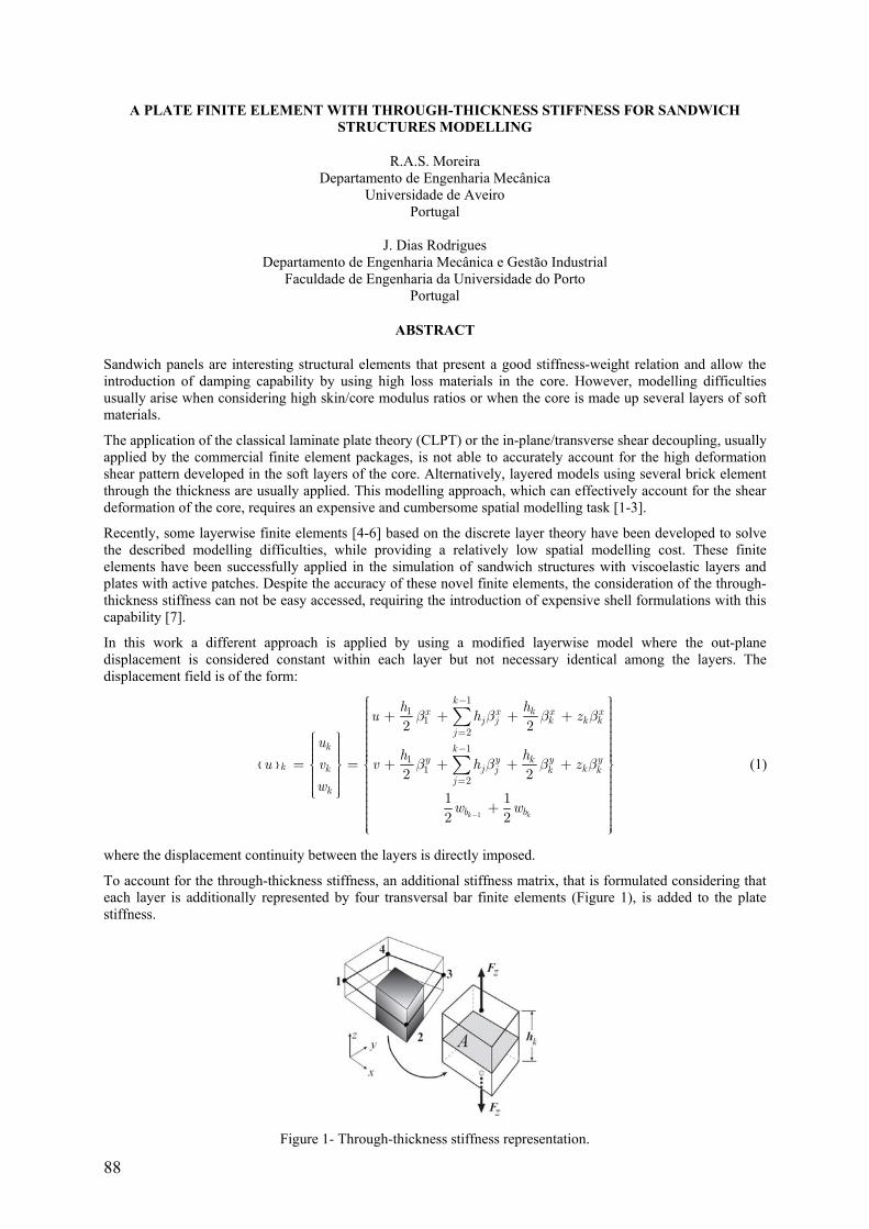
88
A PLATE FINITE ELEMENT WITH THROUGH-THICKNESS STIFFNESS FOR SANDWICH STRUCTURES MODELLING
R.A.S. Moreira Departamento de Engenharia Mecânica
Universidade de Aveiro Portugal
J. Dias Rodrigues
Departamento de Engenharia Mecânica e Gestão Industrial Faculdade de Engenharia da Universidade do Porto
Portugal
ABSTRACT
Sandwich panels are interesting structural elements that present a good stiffness-weight relation and allow the introduction of damping capability by using high loss materials in the core. However, modelling difficulties usually arise when considering high skin/core modulus ratios or when the core is made up several layers of soft materials.
The application of the classical laminate plate theory (CLPT) or the in-plane/transverse shear decoupling, usually applied by the commercial finite element packages, is not able to accurately account for the high deformation shear pattern developed in the soft layers of the core. Alternatively, layered models using several brick element through the thickness are usually applied. This modelling approach, which can effectively account for the shear deformation of the core, requires an expensive and cumbersome spatial modelling task [1-3].
Recently, some layerwise finite elements [4-6] based on the discrete layer theory have been developed to solve the described modelling difficulties, while providing a relatively low spatial modelling cost. These finite elements have been successfully applied in the simulation of sandwich structures with viscoelastic layers and plates with active patches. Despite the accuracy of these novel finite elements, the consideration of the through-thickness stiffness can not be easy accessed, requiring the introduction of expensive shell formulations with this capability [7].
In this work a different approach is applied by using a modified layerwise model where the out-plane displacement is considered constant within each layer but not necessary identical among the layers. The displacement field is of the form:
1
11
121
11
2
2 2
2 2
1 12 2k k
kkx x x x
j j k k kj
k ky y k y y
k k j kj k kj
k
b b
h hu h z
uh h
u v v h zw
w w
β β β β
β β β β
−
−
=−
=
⎧ ⎫⎪ ⎪⎪ ⎪+ + + +⎪ ⎪⎪ ⎪⎪ ⎪⎪ ⎪⎧ ⎫⎪ ⎪ ⎪ ⎪⎪ ⎪ ⎪ ⎪⎪ ⎪ ⎪ ⎪⎪ ⎪ ⎪ ⎪= = + + + +⎨ ⎬ ⎨ ⎬⎪ ⎪ ⎪ ⎪⎪ ⎪ ⎪ ⎪⎪ ⎪ ⎪ ⎪⎪ ⎪ ⎪ ⎪⎩ ⎭ ⎪ ⎪⎪ ⎪+⎪ ⎪⎪ ⎪⎪ ⎪⎪ ⎪⎩ ⎭
∑
∑ (1)
where the displacement continuity between the layers is directly imposed.
To account for the through-thickness stiffness, an additional stiffness matrix, that is formulated considering that each layer is additionally represented by four transversal bar finite elements (Figure 1), is added to the plate stiffness.
Figure 1- Through-thickness stiffness representation.

89
To verify the proposed finite element performance it was compared with a layered model using a stack of brick finite elements (HEXA8) and the MSC.NastranTM commercial package. The natural frequency values of a cantilever sandwich plate (300x200mm) are presented in Table 1. The plate skins are made of 1050A aluminium alloy and have a thickness of 1mm. The thick core (40mm) has a very low modulus when compared with the skin material and represents a soft compressible and incompressible foam. The acronym HHH represents the layered model using brick elements in MSC.NastranTM [3], layw4E is the present finite element and layw4m [6] is a similar layerwise finite element without through-thickness deformation.
Table 2- Natural frequencies of symmetric and antisymmetric modes for the cantilevered sandwich plate [Hz].
Core: compressible foam ν=0.25 Core: incompressible foam ν=0.49
Mode Shape Model HHH layw4E layw4m Model HHH layw4E layw4m F1 3.25 3.26 3.26 3.23 3.24 3.24 T1 10.62 10.70 10.70 10.58 10.66 10.66 F2 19.50 19.67 19.67 19.47 19.64 19.64 T2 35.13 35.64 35.64 35.10 35.61 35.61
F1E 11.34 11.37 -- 41.27 41.40 -- T1E 14.99 15.17 -- 42.06 42.84 -- F2E 22.16 22.40 -- 45.03 45.93 -- T2E 36.60 37.18 -- 53.39 54.84 -- Properties: Skins: h=1mm, E=72GPa, ν=0.32, ρ=2710kg/m3; Core: h=40mm, E=1kPa, ν=0.25/0.49, ρ=1140kg/m3
The symmetric and antisymmetric modes for the cantilevered sandwich plate with a core made of compressible foam, calculated by using the proposed model, are represented in Figure 2.
Figure 2- Symmetric and antisymetric mode shapes of a sandwich plate with soft core.
The proposed finite element was able to predict the symmetric and antisymmetric modes, providing results close to the reference results obtained by the expensive layered model formed by a stack of brick finite elements. Furthermore, the proposed model guarantees directly the displacement field continuity between the layers.
REFERENCES
[1] Lu Y.P., Killian J.W., Evertine G.C., “Vibrations of Three Layered Damped Sandwich Plate Composites”. Journal of Sound and Vibration, 64: 63–71, 1979.
[2] Johnson C.D., Kienholz D.A. “Finite Element Prediction of Damping in Structures with Constrained Viscoelastic Layers”. AIAA Journal 20(9): 1284–1290, 1982.
[3] Moreira R., Rodrigues J.D., “Constrained Damping Layer Treatments: Finite Element Modelling”, Journal of Vibration Control, 10 (4): 575-595, 2004.
[4] Saravanos D.A., Pereira J.M. “Dynamic Characteristics of Specialty Composite Structures with Embedded Damping Layers”. Journal of Vibration and Acoustics 117: 62–69, 1995.
[5] Cupial P., Niziol J. “Vibration and Damping Analysis of a Three-Layered Composite Plate with a Viscoelastic Mid-Layer”. Journal of Sound and Vibration 183(1): 99-114, 1997.
[6] R.A.S. Moreira R.A.S., Dias Rodrigues J., Ferreira A.J.M., “A Generalized Layerwise Finite Element for Multi-Layer Damping Treatments”, Computational Mechanics (DOI:10.007/S00466-005-0714-1), 2005.
[7] El-Abbasi N., Meguid S.A., “A New Shell Element Accounting for Through-Thickness Deformation”, Computer Methods In Applied Mechanics and Engineering, 189: 841-862. 2000.

90
TESTING AND MODELLING OF THE BOND BEHAVIOUR BETWEEN CFRP SHEET AND CURVED MASONRY SUBSTRATE
M.A. Aiello Department of Innovation Engineering, University of Lecce, Via Monteroni, 73100 Lecce, ITALY,
tel. 0832297248, e-mail: [email protected]
P. Corvaglia, A. Fortunato, O. Manni Department of Materials and Structures Engineering, Consorzio CETMA, Cittadella della Ricerca
S.S. 7 km 7+300 per Mesagne, 72100 Brindisi, ITALY, tel. 0831449111, fax 0831449120 e-mail: [email protected], [email protected], [email protected]
F. Pedone
Department of Chemistry, Materials and Chemical Engineering "Giulio Natta", Politecnico di Milano Piazza Leonardo da Vinci 32, 20133 Milano
ABSTRACT
In the field of Civil Engineering, one of the most actual topics is the need for repair and strengthening of reinforced concrete and masonry structures. Among the different kinds of reinforcing materials and techniques, the use of Fiber Reinforced Polymers (FRP) is gaining more and more assents. The reasons for this success, first of all, lies in the low weight of these materials in relation to their high mechanical properties and the good durability. As a consequence the application of this kind of reinforcement is particularly promising [1-4].
However the success of retrofitting techniques depends on more extent on the bond performance between the FRP reinforcement and the substrate. That is, only through a good connection between FRP and concrete or masonry the reinforcement can be effective. In fact, in spite of the high performance of FRP materials, research and practice have demonstrated that the most common type of collapse in FRP reinforced structures is by debonding of composite materials [5-7]. Therefore it is necessary, to investigate about the bonding behaviour between the two materials in order to understand the main properties that mostly affect the interface characteristics and to enhance, consequently, the bond performance.
This paper deals with the study of the bond behaviour of FRP sheets bonded to masonry substrate (Figure 1), In particular, the work focuses on the bond performance of Carbon FRP (CFRP) sheets, with epoxy matrix, applied to a particular kind of limestone ashlars widespread in the Salentine peninsula, the so called “Leccese Stone”.
Such material is commonly used, in the region, for historic vaulted buildings, but the presence of curvature causes the addition of a radial normal stress to the shear stress acting at the FRP-substrate interface, and the combination of the two stresses can cause a premature failure [8-11]. In the work, the influence of curvature on the reduction of the bond performances was investigated by means of four point bending tests carried out on small arches with FRP bonded at the intrados. The influence of the sheet width and of the sheet modulus was also studied. The bonding performance was evaluated in terms of the maximum load and of the strains and stresses distribution along the CFRP sheet at different loading steps.
On the basis of the obtained results, it can be said that increasing the curvature value the ultimate load decreases, as well as the maximum bond stress, i.e. the bond stress value at incoming debonding. In addition, the presence of curvature was found to be influential also on the type of failure; in particular, a more fragile failure was observed when the radial stresses increases as consequence of a curvature increase. The influence of the reinforcement width was finally observed, although further analyses are required in order to better investigate the effect of such parameter.
In order to interpret the obtained experimental results, a theoretical analysis of the stress and strain fields was performed; such analysis appeared effective to predict the interface behaviour at the first stage, up to the debonding start.
Finally, a finite element model of the performed tests was built, in order to make it possible to predict the bond capacity in different conditions and to extend results to more complex structural members.
In consequence of symmetry considerations, only a quarter of the beam was modeled with non-linear solid (for the substrate) and shell (for the FRP) elements. The Drucker – Prager criterion was used to model the plastic behaviour of masonry, while the William - Warnke model allowed to take into account cracking and crushing failure modes. A good agreement with the experimental results was obtained, in terms of maximum load and strains and stresses distributions.

91
The final aim of the work is to provide affordable and handeable design criteria for repairing curved masonry structures by FRP taking into account the effect of curvature on the interface stress field.
Figure 1- Detail of a tested specimen: four point bending test causes detachment of FRP Sheet bonded to the
intrados of the beam
REFERENCES
[1] CEB-FIB Task Group 9.3, “Externally bonded FRP reinforcement for RC structures”, CEB Bullettin 14, 2001.
[2] CNR-DT 200/2004 “Istruzioni per la Progettazione, l’Esecuzione ed il Controllo di Interventi di Consolidamento Statico mediante l’utilizzo di Compositi Fibrorinforzati” Roma, CNR 13 luglio 2004.
[3] Ehsani M R (1995), “Strengthening of Earthquake-Damaged Masonry Structures with Composite Materials, in Non-Metallic (FRP) Reinforcement for Concrete Structures”, L. Taerwe (ed), pp681-687, E&FN Spon, London.
[4] Schwegler G (1995), “Masonry Construction Strengthened with Fiber Composites in Seismically Endangered Zones”, Proceedings of the 10th European Conference on Earthquake Engineering, Balkema, Rotterdam.
[5] M.A. Aiello, M.S. Sciolti, M. Pecce, “Experimental investigation on bond between FRP sheets and natural masonry blocks”, Proceedings of the 10th International Conference STRUCTURAL FAULTS & REPAIR – 2003 (on CD), 1- 3 July 2003, London, U.K.
[6] M. A. Aiello and M.S. Sciolti, “Masonry Structures Strengthened with FRP sheets: Experimental investigation of bond between FRP laminates and Ashlars”, International Journal for Restoration of Buildings and Monuments, Vol. 9, No. 6, 2003, pp. 639-662.
[7] M. A. Aiello and M.S. Sciolti, “Influence of environmental agents on bond between FRP reinforcement and calcarenite ashlars”, Proceedings of the fourth International Seminar on Structural Analysis of Historical Constructions, Padova, Italy, 2004, Balkema Publisher, Vol. 2, pp. 875-881.
[8] M.A. Aiello, N. Galati, A. La Tegola, “Bond Analysis of Curved Structural Concrete Elements Strengthened using FRP Materials”, Proceedings of FRPRCS-5, Cambridge, U.K., 16-18 July 2001.
[9] M.A. Aiello, N. Galati, A. La Tegola, “Effect of curvature on the bond between concrete and CRRP sheets”, Proceedings of the International Conference Advanced Polymer Composites for Structural Applications in Construction, ACIC 2002, 15-17 April 2002, Southampton, U.K., Thomas Telford, London, pp.69-76.
[10] Aiello, L. De Lorenzis, N. Galati, A. La Tegola, “Bond between FRP laminates and curved concrete substrates with anchoring composite spikes”, International Conference on Innovative Materials and Technologies for Constructions and Restoration, IMTCR-04, 6-9 June, Lecce (Italia), 2004.
[11] M.A. Aiello, P. Corvaglia, A. Fortunato, A.M. Marzano, “Bond between Masonry and CFRP Sheets in presence of Curvature”, Proceedings of CCC 2005, Composites in Construction, Lyon (FR), 10-13 June 2005.
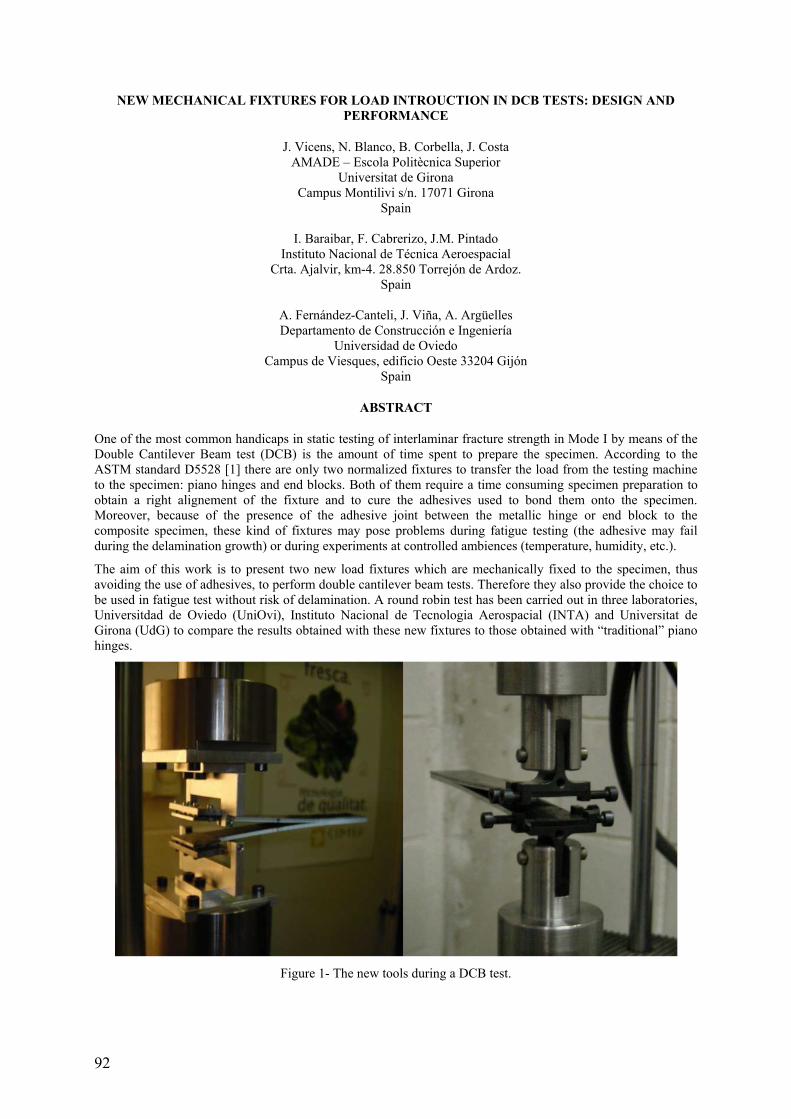
92
NEW MECHANICAL FIXTURES FOR LOAD INTROUCTION IN DCB TESTS: DESIGN AND PERFORMANCE
J. Vicens, N. Blanco, B. Corbella, J. Costa AMADE – Escola Politècnica Superior
Universitat de Girona Campus Montilivi s/n. 17071 Girona
Spain
I. Baraibar, F. Cabrerizo, J.M. Pintado Instituto Nacional de Técnica Aeroespacial
Crta. Ajalvir, km-4. 28.850 Torrejón de Ardoz. Spain
A. Fernández-Canteli, J. Viña, A. Argüelles Departamento de Construcción e Ingeniería
Universidad de Oviedo Campus de Viesques, edificio Oeste 33204 Gijón
Spain
ABSTRACT
One of the most common handicaps in static testing of interlaminar fracture strength in Mode I by means of the Double Cantilever Beam test (DCB) is the amount of time spent to prepare the specimen. According to the ASTM standard D5528 [1] there are only two normalized fixtures to transfer the load from the testing machine to the specimen: piano hinges and end blocks. Both of them require a time consuming specimen preparation to obtain a right alignement of the fixture and to cure the adhesives used to bond them onto the specimen. Moreover, because of the presence of the adhesive joint between the metallic hinge or end block to the composite specimen, these kind of fixtures may pose problems during fatigue testing (the adhesive may fail during the delamination growth) or during experiments at controlled ambiences (temperature, humidity, etc.).
The aim of this work is to present two new load fixtures which are mechanically fixed to the specimen, thus avoiding the use of adhesives, to perform double cantilever beam tests. Therefore they also provide the choice to be used in fatigue test without risk of delamination. A round robin test has been carried out in three laboratories, Universitdad de Oviedo (UniOvi), Instituto Nacional de Tecnologia Aerospacial (INTA) and Universitat de Girona (UdG) to compare the results obtained with these new fixtures to those obtained with “traditional” piano hinges.
Figure 1- The new tools during a DCB test.

93
One of the laboratories participants in the round robin test used piano hinges as ASTM D5528 recomend. The other two laboratories used the new tools. The newness characteristic introduced by these new tools is the way that they are fixed at the specimen. One of the new tools is formed by two inverted T-shaped parts. On top of each part there is a hole to fix the tool to the testing machine with a pin. The specimen is placed between the two parts and fixed at the lateral edges of the specimen with screws. The load during the test is introduced by these contacting screws. The other tool has two main parts aswell, but they are formed by different pieces that are fixed by screws. The point of interest of this tool is that one of these pieces is placed in the middle plane of the specimen and introduces the force during the test by contact surfaces. An insert is required to use this tool. This plane metalic part of the load fixture, once introduced in the specimen, is fixed to the rest of the tool using screws. The use of this tool avoids the use of adhesives during the conditioning of the specimen and also permits to introduce the load at the middle plane of each beam. This is an advantatge because it eliminates the need for correction factors related to the fact that the load point is not on the neutral plane of the beam and to the stiffening effect of the end blocks.
To validate the reliability of these fixtures in different conditions, the round robin test was performed on three different materials under static and fatigue conditions. It was concluded that these new fixtures did not have an influence on the obtained results, but reducing the time required for preparation of the specimens and avoiding bonded jints that can prove to be critical, specially for fatigue tests.
Figure 2- Results from the round robin test classified for materials.
REFERENCES
[1] ASTM D 5528-01. Standard Test Method for Mode I Interlaminar Fracture Toughness of Uniderectional Fiber-Reinforced Polymer Matrix Composites. ASTM Standards., 15.03.

94
TWO-SCALE MODELLING OF THE THERMOMECHANICAL BEHAVIOUR OF METAL MATRIX COMPOSITES
J. Pinho-da-Cruz, J.A. Oliveira, A. Andrade-Campos, F. Teixeira-Dias Departamento de Engenharia Mecânica, Universidade de Aveiro
Campus Universitário de Santiago 3810-193 Aveiro
Portugal
ABSTRACT
Many engineering and scientific problems require a full understanding of physical phenomena that span two or more spatial length scales. The thermomechanical modelling of the behaviour of Metal Matrix Composites (MMCs) is such a case. In fact, constituent thermoelastic properties of metal matrix composites are generally temperature dependent, which affects the effective behaviour of the overall composite.
In this context, the Asymptotic Expansion Homogenisation (AEH) method [1, 2] appears to be the most suitable technique to address this multiscale dependence. Frequently referred to as mathematical homogenisation, AEH is an established approach for determining effective properties of periodic composites, consisting in a suitable approach to estimate the effective thermoelastic properties of complex microstructures.
In the AEH methodology, governing differential equations with rapidly varying coefficients are replaced by differential equations with constant or slowly varying coefficients, derived by asymptotic expansions of the field variables along with the assumption of periodicity. Then, a modified problem, usually denoted by the Y-periodic problem, is generally solved by finite element methods [3]. In fact, several AEH frameworks have been applied to the solution of linear and non-linear structural problems [3, 5]. Moreover, in contrast to other homogenisation approaches, this methodology is useful due to its inherent capability to perform both homogenisation and localisation seamlessly within a single method by considering the microstructural details within a macrolevel analysis.
In the present work, the AEH methodology is applied to the two-scale modelling of the thermomecanical behaviour of metal matrix composites (e.g. AlSiCp MMCs), focusing mainly on engineering issues related to its finite element implementation and applications. Illustrative examples for linear/non-linear and stationary/transient thermomechanic simulations are obtained and validations are provided. These results are presented and thoroughly compared.
Figure 1- (a) Finite element mesh of a MMC unit-cell and (b) reinforcement displacement field obtained by
Asymptotic Expansion Homogenisation (AEH).
REFERENCES
[1] A. Bensoussan, A. Lions, J.L., Papanicolaou G., “Asymptotic Analysis for Periodic Structures”, North-Holland, Amesterdão, Holanda, 1978.

95
[2] Hassani, B., Hinton, E., “A Review of Homogenization and Topology Optimization 1 - Homogenization Theory for Media with Periodic Structure, Computers and Structures, Vol. 69, pp. 707-717, 1998.
[3] Guedes J.M., Kikuchi, N., “Preprocessing and Postprocessing for Materials Based on the Homogenization Method with Adaptive Finite Element Methods, Computer Methods in Applied Mechanics and Engineering, Vol. 83, pp. 143-198, 1990.
[4] Chung P.W., Tamma K.K., Namburu R.R., “Asymptotic Expansion Homogenization for Heterogenous Media: Computational Issues and Applications”, Composites Part A, Vol. 32, pp. 1291-1301, 2001.
[5] Chung P.W., Tamma K.K., Namburu R.R., “On the homogenization of temperature dependent thermal conductivity in composite materials”, AIAA-1999-878, 37th Aerospace Sciences Meeting and Exhibit, 1999.


97
SESSION 6 – DAMAGE MODELS I
Chair: Dr. Christophe Cluzel Laboratoire de Mécanique et Technologie, France
Tuesday 11th April 11:15 – 12:55

98
DAMAGE EVOLUTION IN COMPOSITE LAMINATES WITH MATRIX CRACKS AND FIBER BREAKS
J. Varna1, Johannes Eitzenberger1, M. Megnis2 1Luleå University of Technology, Sweden, SE-971 87, [email protected]
2OSTBY AB, LV-1012, Riga, Latvia
ABSTRACT
Several damage modes may develop during the service life in long fiber composites with unidirectional or multidirectional orientation of the reinforcement. The most typical modes are related to fiber fracture (statistically distributed individual fiber breaks with or without debonding at the interface) and matrix dominated cracking (intralaminar cracks). The modes of microdamage in composites considered in this paper are: a) fiber breaks in unidirectional layers; b) intralaminar cracks in off axis layers of prepreg tape composites, see Figure 1 showing a system of intralaminar cracks in 90-layer of a cross-ply laminate and fiber breaks in 0-layer, which are most typical during fatigue loading.
a) intralaminar cracks
b) fiber breaks in longitudinal layer
Figure 1- Microdamage modes in laminates
These damage modes occur when the material is subjected to mechanical or thermal loading and cause degradation of thermo-elastic properties. Independent on the scale, each damage mode is usually localized in a certain phase (in a fiber, matrix, at the interface, inside a layer etc.) and is characterized by a certain orientation and size. The objective of this study is to use experimental data for modulus and Poisson’s ratio degradation in order to analyze the damage modes in laminates. We use the methodology for stiffness calculation of a damaged laminate developed earlier [1-3] to find the current damage state. The procedure is applicable for damaged composite constituents which are continuous at least in one direction. The used closed form expressions describe the cracking caused macroscopic property change through the constituent properties, composite architecture and local characteristics of the damage- crack face opening (COD) and crack sliding (CSD) displacements. The COD and CSD are determined using simple power laws established based on FEM analysis.
The calculated reduction of the elastic properties of the composite for a fixed state of damage is used to quantify the damage state. In contrast to continuum damage models which also often use stiffness reduction to calculate macroscopic damage parameters, here we obtain a quantitative characterization of each micro damage mode in terms of crack density. The quantification of each damage mode separately is possible because fiber breaks and intralaminar cracks have different effect on the laminate longitudinal modulus and the Poisson’s ratio. The fiber breaks are mainly affecting the modulus whereas the intralaminar cracks have significant effect on Poisson’s ratio as well.
The stiffness matrix of the damaged laminate [ ]LAMQ is calculated as
[ ] [ ] [ ] [ ] [ ] [ ] [ ]1
0 02 1
1 NLAM LAM LAMT
kn kk kkk kk
Q I Q T U T Q S t QhE
ρ−
=
⎛ ⎞⎟⎜ ⎡ ⎤ ⎡ ⎤ ⎟= +⎜ ⎟⎣ ⎦ ⎣ ⎦⎜ ⎟⎜⎝ ⎠∑ (1)
In (1) [ ]0LAMQ and [ ]0
LAMS are the stiffness and compliance of the undamaged laminate, [ ]I is identity matrix, ρkn is normalized crack density and E2 is the transverse modulus of the unidirectional composite. The [ ]kU matrix represents the COD and CSD of a crack in a layer symmetry axes. For intralaminar cracks

99
[ ] 2
21
12
0 0 0
2 0 0
0 0
kank
kan
U u
E uG
⎡ ⎤⎢ ⎥⎢ ⎥⎢ ⎥⎢ ⎥= ⎢ ⎥⎢ ⎥⎢ ⎥⎢ ⎥⎣ ⎦
(2)
The u1an and u2an depend on the cracked layer and supporting layer thickness and stiffness ratio.
2 122 1
'
nn
an ans sx xy
E Gu A B u A B
E G⎡ ⎤⎛ ⎞⎛ ⎞ ⎟⎜⎟ ⎢ ⎥⎜= + = + ⎟⎜⎟⎜ ⎟⎟⎜ ⎟⎜⎢ ⎥⎝ ⎠ ⎝ ⎠⎣ ⎦
(3)
Fibers are usually broken only in layers oriented in the main load direction and therefore the crack opening is significantly larger than the crack face sliding. The effect of fiber ends on other elastic properties considering aligned short fiber composites, which is a particular case of the analysed, is usually neglected. Then the [ ]kU has the form
[ ]1
0
0 0
2 0 0 0
0 0 0
u
U
⎡ ⎤⎢ ⎥⎢ ⎥= ⎢ ⎥⎢ ⎥⎢ ⎥⎣ ⎦
(4)
The value of u1 in (4) depends on the extent of the debonding at the fiber/matrix interface. FEM calculations were performed to calculate the COD of the penny-shaped crack and the effect of fiber volume fraction and elastic properties was described by a simple law.
The predicted elastic modulus reduction due to intralaminar cracks in the 90-layer is shown in Figure 2a) whereas the modulus reduction in unidirectional composite due to fiber breaks is shown in Figure 2b).
Figure 2- Stiffness reduction in laminates: a) intralaminar cracking effect on shear modulusin cross-ply laminate:
model and FEM calculation; b) fiber break effect on longitudinal modulus of UD composite.
The fiber crack density in afiber is limited by the ineffective fiber lengths which for the considered composite is about 0.15mm.
The curves in Figure 2 are used to determine the crack density development with strain using the known elastic modulus versus strain data [4].
REFERENCES
[1] Lundmark P. and Varna J., “Constitutive Relationships for Laminates with Ply Cracks in In-plane Loading”, International Journal of Damage Mechanics (2005); 14 (3); 235-261.
[2] Lundmark P. and J. Varna, Crack face sliding effect on stiffness of laminates with ply cracks, Composites Science and Technology, 2005, in press.
[3] J. Varna, P. Lundmark, M. Megnis and D. Mattsson, Constitutive models for composite laminates with matrix cracks and fiber breaks, Proc. of 4th Intern. Conf. on Fracture and Damage Mechanics, 12-14 July 2005, Mallorca, Spain. 597-604.
[4] M. Megnis, Characterization of Internal State Variable for fiber fracture in UD Composite, ICCES 04, July 2004, Madeira, Portugal.
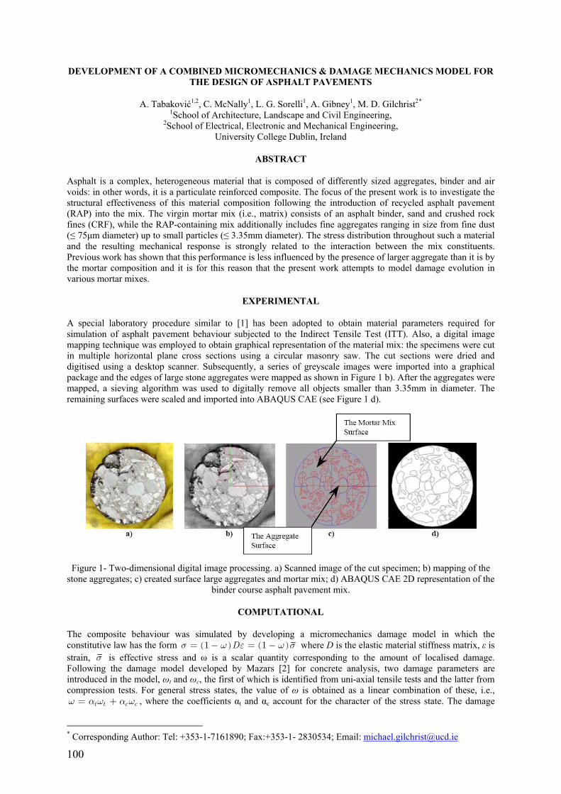
100
DEVELOPMENT OF A COMBINED MICROMECHANICS & DAMAGE MECHANICS MODEL FOR THE DESIGN OF ASPHALT PAVEMENTS
A. Tabaković1,2, C. McNally1, L. G. Sorelli1, A. Gibney1, M. D. Gilchrist2* 1School of Architecture, Landscape and Civil Engineering,
2School of Electrical, Electronic and Mechanical Engineering, University College Dublin, Ireland
ABSTRACT
Asphalt is a complex, heterogeneous material that is composed of differently sized aggregates, binder and air voids: in other words, it is a particulate reinforced composite. The focus of the present work is to investigate the structural effectiveness of this material composition following the introduction of recycled asphalt pavement (RAP) into the mix. The virgin mortar mix (i.e., matrix) consists of an asphalt binder, sand and crushed rock fines (CRF), while the RAP-containing mix additionally includes fine aggregates ranging in size from fine dust (≤ 75μm diameter) up to small particles (≤ 3.35mm diameter). The stress distribution throughout such a material and the resulting mechanical response is strongly related to the interaction between the mix constituents. Previous work has shown that this performance is less influenced by the presence of larger aggregate than it is by the mortar composition and it is for this reason that the present work attempts to model damage evolution in various mortar mixes.
EXPERIMENTAL
A special laboratory procedure similar to [1] has been adopted to obtain material parameters required for simulation of asphalt pavement behaviour subjected to the Indirect Tensile Test (ITT). Also, a digital image mapping technique was employed to obtain graphical representation of the material mix: the specimens were cut in multiple horizontal plane cross sections using a circular masonry saw. The cut sections were dried and digitised using a desktop scanner. Subsequently, a series of greyscale images were imported into a graphical package and the edges of large stone aggregates were mapped as shown in Figure 1 b). After the aggregates were mapped, a sieving algorithm was used to digitally remove all objects smaller than 3.35mm in diameter. The remaining surfaces were scaled and imported into ABAQUS CAE (see Figure 1 d).
Figure 1- Two-dimensional digital image processing. a) Scanned image of the cut specimen; b) mapping of the
stone aggregates; c) created surface large aggregates and mortar mix; d) ABAQUS CAE 2D representation of the binder course asphalt pavement mix.
COMPUTATIONAL
The composite behaviour was simulated by developing a micromechanics damage model in which the constitutive law has the form ( ) ( )1 1Dσ ω ε ω σ= − = − where D is the elastic material stiffness matrix, ε is strain, σ is effective stress and ω is a scalar quantity corresponding to the amount of localised damage. Following the damage model developed by Mazars [2] for concrete analysis, two damage parameters are introduced in the model, ωt and ωc, the first of which is identified from uni-axial tensile tests and the latter from compression tests. For general stress states, the value of ω is obtained as a linear combination of these, i.e.,
t t c cω α ω α ω= + , where the coefficients αt and αc account for the character of the stress state. The damage
* Corresponding Author: Tel: +353-1-7161890; Fax:+353-1- 2830534; Email: [email protected]
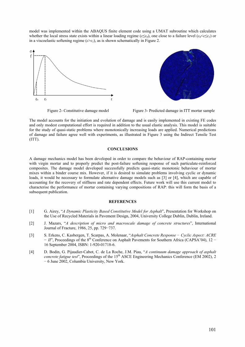
101
model was implemented within the ABAQUS finite element code using a UMAT subroutine which calculates whether the local stress state exists within a linear loading regime (ε≤ε0), one close to a failure level (ε0<ε≤ε1) or in a viscoelastic softening regime (ε>ε1), as is shown schematically in Figure 2.
Figure 2- Constitutive damage model Figure 3- Predicted damage in ITT mortar sample
The model accounts for the initiation and evolution of damage and is easily implemented in existing FE codes and only modest computational effort is required in addition to the usual elastic analysis. This model is suitable for the study of quasi-static problems where monotonically increasing loads are applied. Numerical predictions of damage and failure agree well with experiments, as illustrated in Figure 3 using the Indirect Tensile Test (ITT).
CONCLUSIONS
A damage mechanics model has been developed in order to compare the behaviour of RAP-containing mortar with virgin mortar and to properly predict the post-failure softening response of such particulate-reinforced composites. The damage model developed successfully predicts quasi-static monotonic behaviour of mortar mixes within a binder course mix. However, if it is desired to simulate problems involving cyclic or dynamic loads, it would be necessary to formulate alternative damage models such as [3] or [4], which are capable of accounting for the recovery of stiffness and rate dependent effects. Future work will use this current model to characterise the performance of mortar containing varying compositions of RAP: this will form the basis of a subsequent publication.
REFERENCES
[1] G. Airey, “A Dynamic Plasticity Based Constitutive Model for Asphalt”, Presentation for Workshop on the Use of Recycled Materials in Pavement Design, 2004, University College Dublin, Dublin, Ireland.
[2] J. Mazars, “A description of micro and macroscale damage of concrete structures”, International Journal of Fracture, 1986, 25, pp. 729−737.
[3] S. Erkens, C. Kasbergen, T. Scarpas, A. Molenaar, “Asphalt Concrete Response − Cyclic Aspect: ACRE − II”, Proceedings of the 8th Conference on Asphalt Pavements for Southern Africa (CAPSA’04), 12 − 16 September 2004, ISBN: 1-920-01718-6.
[4] D. Bodin, G. Pijaudier-Cabot, C. de La Roche, J.M. Piau, “A continuum damage approach of asphalt concrete fatigue test”, Proceedings of the 15th ASCE Engineering Mechanics Conference (EM 2002), 2 − 6 June 2002, Columbia University, New York.

102
PROGRESSIVE DAMAGE MODELING IN FIBER-REINFORCED MATERIALS
Ireneusz Lapczyk Standard Mechanics Group
Abaqus, Inc. Providence, RI 02909
U.S.A.
ABSTRACT
This paper presents an anisotropic damage model suitable for predicting failure and post-failure behavior in fiber-reinforced materials. In the model the plane stress formulation is used and the response of the undamaged material is assumed to be linearly elastic. The model is intended to predict behavior of elastic-brittle materials that show no significant plastic deformation before failure.
In the model four different failure modes -- fiber tension, fiber compression, matrix tension, and matrix compression -- are considered and modeled separately. The onset of damage is predicted using Hashin's initiation criteria [I], which are expressed in terms of effective stresses. Once the damage process starts, it is assumed that its effect can be taken into account by modifying the stiffness coefficients. In this model, we adapt the formulation of Matzenrniller et al. [2]. In this formulation the damage is simulated by four internal variables (a different variable is used for each failure mode). An important characteristic of the formulation is that the thermodynamic forces are always positive. Therefore to assure positive dissipation during the damage process it is sufficient to require that the damage variables either remain constant or increase their values. To describe the evolution of the damage variables we use a law that is a generalization of that proposed by Camanho and Davila [3] for cohesive elements. The evolution law is based on energy dissipation during the damage process, which can have a different value for each failure mode. Once an initiation criterion is satisfied, the damage variable will increase if appropriately defined equivalent displacements increase.
Mesh sensitivity is a common problem that occurs when the behavior of materials with damage is modeled numerically. In this model the problem is alleviated by introducing a characteristic length into the formulation. The characteristic length is based on the element geometry; it is assumed to be equal to the square root of the integration point area.
Material models exhibiting softening behavior and stiffness degradation often lead to severe convergence difficulties in implicit analysis programs. In order to overcome some of these convergence difficulties viscous regularization of the constitutive equations is used, which causes the tangent stiffness matrix of the softening material to be positive for sufficiently small time increments. In this model different values of viscous coefficients can be specified for different failure modes.
The model is applied to predict strength of a blunt notched laminate, and the numerical and experimental results show a good agreement.
REFERENCES
[1] Hashin, Z., "Failure Criteria for Unidirectional Fiber Composites", Journal of Applied Mechanics, Vol. 47, pp. 329 334, 1980.
[2] Matzenmiller, A., J, Lubliner, J., Taylor, R. L., "A Constitutive Model for Anisotropic Damage in Fiber-Composites", Mechanics of Materials, Vol. 20, pp. 125-152, 1995.
[3] Carnanho, P. P., and C. G. Davila, "Mixed-Mode Decohesion Finite Elements for the Simulation of Delamination in Composite Materials", NASAITM-2002-211737, pp. 1-37, 2002.

103
PHYSICALLY BASED FAILURE CRITERIA FOR PREDICTION OF DAMAGE EVOLUTON IN COMPOSITE MATERIALS SUBJECTED TO IMPACT LOADING
J. Wiegand, B. Elliott, N. Petrinic Solid Mechanics and Materials Engineering Group
Department of Engineering Science, University of Oxford, Parks Road, Oxford, OX1 3PJ, UK [email protected]
ABSTRACT
This paper presents a newly developed 3D constitutive model for numerical simulation of the response of composite materials subjected to impact loading by means of explicit finite element analysis. The development was motivated by the requirements raised in aircraft and aeroengine manufacturing industries as a result of the deficiencies of constitutive models in commercial software. The research was inspired by the established methodology for experimental characterisation of composite materials at elevated rates of strain.
The new material model relies upon the continuum representation of material behaviour within a representative volume element (RVE). The size of the RVE is given by the 'characteristic length' of the finite element under consideration and the material orientation within this finite element. The element’s load carrying capacity is assessed by means of stress based failure criteria which address all experimentally observable failure modes. A damage mechanics approach is adopted in which the evolution of damage is determined by the rate at which the failure surfaces separating the admissible from inadmissible stress states are exceeded. The evolution of damage in specific materials is controlled by a set of physically based material parameters which define the rate at which the failure surfaces shrink, thus representing the observable strain softening, strain localization and fracture of experimentally assessed materials. A numerically stable stress return mapping algorithm is employed to calculate the admissible stress state during the softening process.
The formulation of the constitutive model allows for its application to different generally orthotropic long fibre composite materials including laminated (UD, X-ply, woven), 3D woven fabrics as well as fibre metal laminates.
The model has been implemented into the in-house software DEST as well as into DYNA which is used by the industry for prediction of composite materials response during impact events such as bird strike. The rate dependent material properties for the model verification have been determined and identified using Split-Hopkinson-Bar devices and inverse modelling. The performance of the developed model is assessed using impact bending experiments in order to illustrate the improvements in accuracy and numerical stability of the model over previously available models.
REFERENCES
[1] Clegg, R.A., White, D.M., Hayhurst, C., Riedel, W., Harwick, W., Hiermaier, S., “Advanced numerical models and material characterisation techniques for composite materials subjected to impact and shock wave loading”, Journal de Physique IV, 110(Sep), pp. 311-316, 2003.
[2] Johnson, A.F., Pickett, A.K., Rozycki, P., “Computational methods for predicting impact damage in composite structures”, Composites Science and Technology, 61, pp. 2183-2192, 2001.
[3] Hou, J.P., Petrinic, N., C. Ruiz, C., “A delamination criterion for laminated composites under lowvelocity impact”, Composites Science and Technology, 61, pp. 2069-2074, 2001.
[4] Elliott, B.C.F., Petrinic, N., “Strategies for efficiency in inverse modelling of material parameters for predictive modelling of aerospace alloys”, 3rd MIT Conference on Computational Fluid and Solid Mechanics, K.J. Bathe (ed.), Elsevier, 2005.


105
SESSION 7 – FULL FIELD TECHNIQUES
Chair: Dr. William Broughton National Physics Laboratory, United Kingdom
Tuesday 11th April 14:00 – 15:40
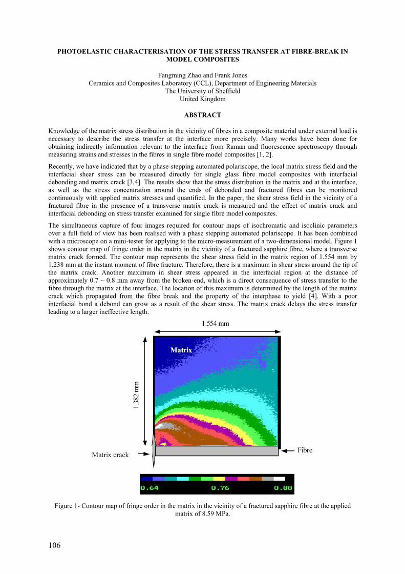
106
PHOTOELASTIC CHARACTERISATION OF THE STRESS TRANSFER AT FIBRE-BREAK IN MODEL COMPOSITES
Fangming Zhao and Frank Jones Ceramics and Composites Laboratory (CCL), Department of Engineering Materials
The University of Sheffield United Kingdom
ABSTRACT
Knowledge of the matrix stress distribution in the vicinity of fibres in a composite material under external load is necessary to describe the stress transfer at the interface more precisely. Many works have been done for obtaining indirectly information relevant to the interface from Raman and fluorescence spectroscopy through measuring strains and stresses in the fibres in single fibre model composites [1, 2].
Recently, we have indicated that by a phase-stepping automated polariscope, the local matrix stress field and the interfacial shear stress can be measured directly for single glass fibre model composites with interfacial debonding and matrix crack [3,4]. The results show that the stress distribution in the matrix and at the interface, as well as the stress concentration around the ends of debonded and fractured fibres can be monitored continuously with applied matrix stresses and quantified. In the paper, the shear stress field in the vicinity of a fractured fibre in the presence of a transverse matrix crack is measured and the effect of matrix crack and interfacial debonding on stress transfer examined for single fibre model composites.
The simultaneous capture of four images required for contour maps of isochromatic and isoclinic parameters over a full field of view has been realised with a phase stepping automated polariscope. It has been combined with a microscope on a mini-tester for applying to the micro-measurement of a two-dimensional model. Figure 1 shows contour map of fringe order in the matrix in the vicinity of a fractured sapphire fibre, where a transverse matrix crack formed. The contour map represents the shear stress field in the matrix region of 1.554 mm by 1.238 mm at the instant moment of fibre fracture. Therefore, there is a maximum in shear stress around the tip of the matrix crack. Another maximum in shear stress appeared in the interfacial region at the distance of approximately 0.7 ~ 0.8 mm away from the broken-end, which is a direct consequence of stress transfer to the fibre through the matrix at the interface. The location of this maximum is determined by the length of the matrix crack which propagated from the fibre break and the property of the interphase to yield [4]. With a poor interfacial bond a debond can grow as a result of the shear stress. The matrix crack delays the stress transfer leading to a larger ineffective length.
Figure 1- Contour map of fringe order in the matrix in the vicinity of a fractured sapphire fibre at the applied
matrix of 8.59 MPa.
107
Furthermore, at a higher applied matrix stress, the shear stress concentration in this region causes a debond to propagate which results in a significant change in the photoelastic response. We observe that yielding of the matrix in the interface region is followed by the propagation of a debond. These shear stress profiles at the debonded and bonded interface will be described in detail, providing a quantification of the effects of the interfacial adhesion, matrix cracking and debonding on stress transfer.
REFERENCES
[1] Galiotis, C., Young, R.J., Yeung, P.H.J., Batchelder, D.N., “The study of model polydiacetylene/epoxy composites”, Journal of Materials Science, Vol. 19, pp.3640, 1984.
[2] Yang, X., Young, R.J., “Determination of residual strains in ceramic-fibre reinforced composites using fluorescence spectroscopy”, Acta Metall Materials, Vol. 43, pp.2407-2416, 1995.
[3] Zhao, F.M., Hayes, S.A., Patterson, E.A., Young, R.J., Jones, F.R., “Measurement of micro stress fields in epoxy matrix around a fibre using phase-stepping automated photoelasticity”, Composites Science and Technology, Vol. 63, No. 12, pp. 1783-1787, 2003.
[4] Zhao, F.M., Martin, R.D.S., Hayes, S.A., Patterson, E.A., Young, R.J., Jones, F.R., “Photoelastic analysis of matrix stresses around a high modulus sapphire fibre by means of phase-stepping automated polariscope”, Composites Part A, Vol. 36, No. 2, pp. 229-244, 2005.

108
IDENTIFICATION OF ELASTIC AND DAMAGE PARAMETERS USING DIGITAL IMAGE CORRELATION TECHNIQUE FOR BRAID REINFORCED COMPOSITES
M. R. C. Fouinneteau, A. K. Pickett School of Industrial and Manufacturing Science
Cranfield University, UK
R. Lichtenberger LIMESS Messtechnik & Software GmbH,
Walther-Rathenau-Str. 13, 75180 Pforzheim, Germany
ABSTRACT
Advanced composites are usually designed to maximise stiffness and load bearing capacity; this generally results in a semi-brittle fibre dominated rupture when failure occurs. This approach is desirable for most applications; however, composites can also be designed to absorb high levels of impact or crash energy. In this case a different design approach is desirable in which fabric shearing mechanisms that enable large material strains and energy absorption prior to ultimate fibre failure must be activated. This paper presents work on material characterisation and damage modelling of braid reinforced composites that have the capacity to undergo large shear strains and energy absorption. These material types are currently being considered for certain automotive applications, such as a front bumper and cross members where high stiffness, low weight and good crash behaviour is required.
Shear strain measurement
An elasto-plastic with damage constitutive law [1] is currently under investigation by the authors to describe shear damage in braid reinforced composites. Characterisation of this model requires experimental shear strain measurements. Conventional strain measuring techniques, such as strain gages and extensometers, are unable to cope with the extensive surface damage and large deformations (>3%) that occur, Figure 1. Consequently, an alternative optical method based on the Digital Image Correlation technique (DIC) [2] is used.
The Digital Image Correlation technique involves application of a speckle pattern to the specimen surface; strain evolution is monitored during loading by a sequence of photographs and digital post-processing of movement between the speckles to determine deformations and strains (εxx, εyy, εxy). Figure 2 shows the equipment setup for tensile loading a [±45°]2S STS/LY3505 carbon fibre braid reinforced composite coupon. This technique allows the complete strain field to failure to be determined. Tensile (and compression) testing in the fibre direction is readily undertaken to determine stiffness and failure data in these directions.
Theoretical model to describe intra-ply failure
The mechanical model used for failure and post-failure prediction is based on the meso-mechanical damage model first proposed by Ladevèze and Le Dantec for uni-directional laminates [3] and adapted [1] for glass and carbon braided composites. Model calibration is based on a simple test procedure such as loading a [0-90]2S coupon under tension and compression and a [±45°] coupon under cyclic loading which allows determination of orthotropic ply stiffness data (E11
T, E11C, E22
T, ν12T, G12), fibre failure strain limits (ε11
T, ε11C), shear damage and
plasticity laws. Latest improvements on the failure law characterisation have been realised due to DIC which enables full measurement of the material strain field even for large shear deformation and surface degradation as shown in Figure 3. The slightly erratic data acquisition in the later stages of the shear stress versus shear strain plot are due to surface degradation causing the speckle pattern to break up; never-the-less meaningful data points are still obtained.
Figure 1- Strain gage failure
Figure 2- The DIC setup and test specimen

109
Figure 3- Cyclic tension loading of a [±45°]2S STS/LY3505 fibre braided composite: a) Shear strain map, b) Plot
of cyclic shear stress versus shear strain, c) Fibre re-orientation leading to necking.
For validation, the new model has been implemented into shell elements of a commercial explicit Finite Element code [4] to predict damage evolution, fibre rotation and failure of the braided composite. Figure 4 shows example test and simulations results for a [±30°]2S carbon fibre braided beam loaded under four point bending. A good correlation between experimental and simulation results was found for both the maximum load capacity of the beam and the location and mode of failure.
Figure 4- Test and simulation results for the 4 point loading to failure of an STS/LY3505 carbon fibre braided
composite beam.
REFERENCES
[1] Pickett, A.K., Fouinneteau, M.R.C., “Material characterisation and calibration of a meso-mechanical damage model for braid reinforced composites”, Composites: Part A, accepted march 2005 and to be published.
[2] http://www.limess.com, LIMESS Messtechnik & Software GmbH, Walther-Rathenau-Str. 13, 75180 Pforzheim.
[3] Ladevèze, P., Le Dantec, E., “Damage modelling of the elementary ply for laminated composites”. Composites Science and Technology 43, 257-267. 92.
[4] Pam-Crash solver note manual 2004. ESI software.

110
THROUGH-THICKNESS FIELD MEASUREMENT IN A COMPOSITE/ALUMINIUM ADHESIVE JOINT
Marie-Pierre Moutrille Katell Derrien Didier Batiste
LIM – UMR CNRS 8006-ENSAM Paris
Michel Grédiac Xavier Balandraud
LaMI research group, Blaise Pascal University, French Institute for Advanced Mechanics (IFMA) Clermont-Ferrand
ABSTRACT
Composite patches are presently used to reinforce damaged structures. On the one hand this technique allows repairing the damaged structures. On the other hand it improves mechanical properties and extends life of structures.
The response in terms of strains, displacements and stresses of an adhesive bonded joint and particularly the stress transfer between substrate and adherent has been already studied. Many theoretical and numerical mechanical models are available in the literature [1] [2]. The load transfer from the substrate to adherent induces shear stress concentrations in the adhesive near the free edges, along the so-called “transfer length”. There is however few experimental studies which made it possible to characterize the in situ mechanical response of the adhesive.
The main purpose of this paper is to present an experimental way to determine the strain and stress field in the adhesive layer during loading of the structure. The initial state of stress in the adhesive, resulting from the bonding process, is also assessed in the present work.
The initial stress state of adhesive is first determined by X-ray diffraction (XRD). As adhesive is a non-crystalline material, aluminium powder has been embedded in the adhesive during the bonding process. The strain is measured in the aluminium. By considering an elastic behaviour of the aluminium powder, the stresses are reduced. Thanks to a homogenisation method, initial stresses in the adhesive are then calculated.
Particles have a maximum diameter of 15 μm. Volume concentration of aluminium particles reaches 6.7%. The X-ray diffraction stress measurement is made using a Phillips X’Pert Goniometer with a Cu Kα radiation.
Two components of the stress tensor are obtained: σxx and σyy. Measurements are performed at different points along the adhesive joint (Y direction, Figure 1). Experiments are performed twice to improve the reliability of results.
Figure 1- Sample used for XRD.
In the aluminium particles, σxx value range between -4 and 7 MPa and σyy value range between -3 and 2 MPa. Those measured stresses correspond to a low level of stress in the adhesive (less than 3 MPa). That's why we can consider initial stress state as negligible.
As the initial mechanical state is known, strain field under loading of the structure can be measured and the corresponding stress field can be determined. Therefore digital image correlation (DIC) seems to be an appropriate technique.
DIC allows the determination of the displacement field on the surface of specimens during mechanical loading. Images are taken with a CCD video camera connected to a computer. As the thickness of the adhesive layer is smaller than 0.5 mm, it is necessary to use a long distance microscope. CorreliLMT software carries out the algorithm of correlation, which calculates the displacement field and then the strain field.

111
Specimens consist of 2024-T3 aluminium plates reinforced with carbon epoxy unidirectional composite. The adhesive is a structural epoxy resin. Two types of specimens are tested to assess the influence of the stiffness ratio between composite and aluminium substrate: carbon fibres oriented at 0° (direction of the load) and carbon fibres oriented at 90°. For each type, 4 different thicknesses of adhesive layer are tested: 0.1mm, 0.2mm, 0.4mm, and 0.5mm. Specimens are subjected to tension loading. Several pictures are taken along the load transfer length (see Figure 2).
Figure 2- Loading of the sample and stress transfer area.
CorreliLMT gives the displacement field in the Region of Interest (ROI) selected before calculation. The strain map is then deduced, especially the shear strain in the adhesive layer. A typical shear strain contour at the eft-hand side of the corresponding selected area is plotted in Figure 3.
Figure 3- Picture of the selected area and shear strain corresponding cartography.
Results are then compared with a finite element simulation (see Figure 4) and with some theoretical models developed under the assumption of a linear elastic response of the different materials.
The various experimental devices used in the experiments will be described in the presentation. The comparison between experimental, numerical and theoretical results will also be discussed.
Figure 4- Result in terms of shear strains of a finite element simulation carried out by Ansys.
REFERENCES
[1] Tsai M.Y., Morton J., An evaluation of analytical and numerical solutions to the single-lap joint, International Journal of Solids and Structures, vol. 31, no. 18, pages 2537-2563, 1994.
[2] Tsai M.Y., Oplinger D. W., Morton J., Improved theoretical solutions for adhesive lap joints, International Journal of Solids and Structures, vol. 35, no. 12, pages 1163-1185, 1998.

112
OPTICAL FULL-FIELD ASSESSMENT OF THE DAMAGE PROGRESSION IN A COMPOSITE OPEN-HOLE TENSION TEST
Fabrice PIERRON*,**, Ben GREEN**, Michael R. WISNOM** *ENSAM – LMPF, Rue St Dominique, BP 508, 51000 Châlons en Champagne, France
**Aerospace Engineering, Queen’s Building, University Walk, Bristol University, BS8 1TR, UK
ABSTRACT
This paper deals with the application of an optical full-field measurement technique to investigate the damage process in a laminated composite submitted to an open hole tension test. This study is part of a wider project at the University of Bristol to study scaling effects in notched composites.
A schematic of the test configuration is given in Figure 1. The material is Hexcel E Glass/913 epoxy composite. Two different lay-ups were studied: [-454/904/454/04]S and [-45/90/45/0]4S to investigate the effect of two different scaling procedures: ply-level scaling (PS) and sublaminate scaling (SS).
Figure 1- Test configuration.
The specimens are equipped with cross-line grids transferred using the procedure described in [1]. The grids are digitized using a PixelFly 12 bit camera. Pictures are taken throughout the loading at regular intervals, so that between two consecutive images, the maximum relative displacement of any point remains less than the grid pitch, so that no spatial unwrapping is necessary. All the images are then processed using spatial phase shifting to produce the two components of the displacement field all along the test.
Figure 2 shows an example of the displacement maps obtained.
Figure 2- Displacement field for a load of 4.8 kN, ply scaling specimen.
In order to derive strains from these noisy displacement maps, different procedures are available. It was found that polynomial fitting of the data was a very efficient way of filtering the noise. A systematic study based on FE simulated maps showed that degree 17 was necessary to reproduce the local gradients near the hole. Then, from the fitted displacements, a closed-form differentiation gives the three in-plane strain components, as shown on Figure 3. The interesting thing is that such strain maps are obtained throughout the loading history of the specimen. Assuming that the beginning of the response is linear elastic up to 4.8 kN (about one third of the load before the first surface crack that appears at about 14 kN for this specimen), it is then possible to construct for each subsequent strain map the difference between the current strain map and the linear extrapolation of the map at 4.8 kN. Therefore, one can see the onset and the development of the material non-linearity near the hole. Figure 4 gives the evolution of this non-linearity on the longitudinal strain map.
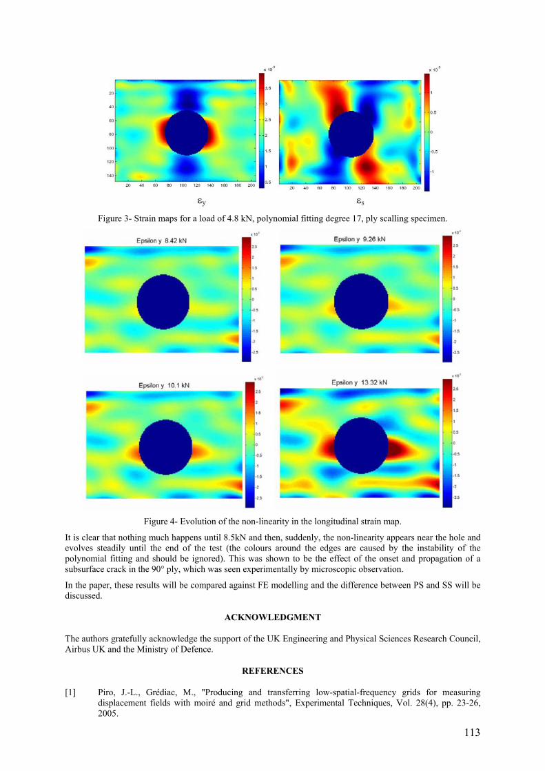
113
Figure 3- Strain maps for a load of 4.8 kN, polynomial fitting degree 17, ply scalling specimen.
Figure 4- Evolution of the non-linearity in the longitudinal strain map.
It is clear that nothing much happens until 8.5kN and then, suddenly, the non-linearity appears near the hole and evolves steadily until the end of the test (the colours around the edges are caused by the instability of the polynomial fitting and should be ignored). This was shown to be the effect of the onset and propagation of a subsurface crack in the 90° ply, which was seen experimentally by microscopic observation.
In the paper, these results will be compared against FE modelling and the difference between PS and SS will be discussed.
ACKNOWLEDGMENT
The authors gratefully acknowledge the support of the UK Engineering and Physical Sciences Research Council, Airbus UK and the Ministry of Defence.
REFERENCES
[1] Piro, J.-L., Grédiac, M., "Producing and transferring low-spatial-frequency grids for measuring displacement fields with moiré and grid methods", Experimental Techniques, Vol. 28(4), pp. 23-26, 2005.


115
POSTER SESSION 4
Tuesday 11th April 15:40 – 16:20
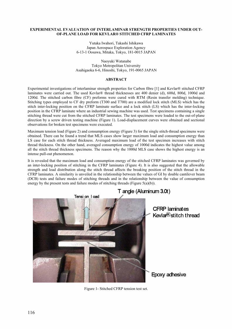
116
EXPERIMENTAL EVALUATION OF INTERLAMINAR STRENGTH PROPERTIES UNDER OUT-OF-PLANE LOAD FOR KEVLAR® STITCHED CFRP LAMINATES
Yutaka Iwahori, Takashi Ishikawa Japan Aerospace Exploration Agency
6-13-1 Oosawa, Mitaka, Tokyo, 181-0015 JAPAN
Naoyuki Watanabe Tokyo Metropolitan University
Asahigaoka 6-6, Hinoshi, Tokyo, 191-0065 JAPAN
ABSTRACT
Experimental investigations of interlaminar strength properties for Carbon fibre [1] and Kevlar® stitched CFRP laminates were carried out. The used Kevlar® thread thicknesses are 400 denier (d), 600d, 800d, 1000d and 1200d. The stitched carbon fibre (CF) preforms were cured with RTM (Resin transfer molding) technique. Stitching types employed to CF dry preform (T300 and T700) are a modified lock stitch (MLS) which has the stitch inter-locking position on the CFRP laminate surface and a lock stitch (LS) which has the inter-locking position in the CFRP laminate where an industrial sewing machine was used. Test specimens containing a single stitching thread were cut from the stitched CFRP laminates. The test specimens were loaded to the out-of-plane direction by a screw driven testing machine (Figure 1). Load-displacement curves were obtained and sectional observations for broken test specimens were executed.
Maximum tension load (Figure 2) and consumption energy (Figure 3) for the single stitch-thread specimens were obtained. There can be found a trend that MLS cases show larger maximum load and consumption energy than LS case for each stitch thread thickness. Averaged maximum load of the test specimen increases with stitch thread thickness. On the other hand, averaged consumption energy of 1000d indicates the highest value among all the stitch thread thickness specimens. The reason why the 1000d MLS case shows the highest energy is an intense pull-out phenomenon.
It is revealed that the maximum load and consumption energy of the stitched CFRP laminates was governed by an inter-locking position of stitching in the CFRP laminates (Figure 4). It is also suggested that the allowable strength and load distribution along the stitch thread affects the breaking position of the stitch thread in the CFRP laminates. A similarity is unveiled in the relationship between the values of GI by double cantilever beam (DCB) tests and failure modes of stitching threads and in the relationship between the value of consumption energy by the present tests and failure modes of stitching threads (Figure 5(a)(b)).
Figure 1- Stitched CFRP tension test set.

117
Figure 2- Maximum load-Thread thickness plots. Figure 3- Consumption energy-Thread thickness plots.
Min. Load/Energy Max- Load Max. Energy
800d
Figure 4- Fracture modes of the tension test specimens.
Figure 5- Fractured stitch threads after DCB tests: (a) 800d MLS; (b) 1200d LS.
REFERENCES
[1] Y. Iwahori, T. Ishikawa, N. Watanabe and A. Ito, “Experimental evaluation for interlaminar fracture toughness of stitched CFRP laminates”, SAMPE Fall Technical Conference (37th ISTC), Seattle (2005).

118
THE EFFECT OF FIBRE REINFORCEMENT ON THE THERMALLY INDUCED RESIDUAL STRESS FIELDS OF METAL MATRIX COMPOSITES
A. Andrade-Campos, J. Pinho-da-Cruz, J.A. Oliveira, F. Teixeira-Dias Departamento de Engenharia Mecânica, Universidade de Aveiro
Campus Universitário de Santiago 3810-193 Aveiro
Portugal
ABSTRACT
The study of the thermal distribution and heat dissipation in Metal Matrix Composite materials (MMCs) is of extreme relevance for the understanding of the behaviour of these materials and their applications. The influence of the temperature distribution in the thermomechanical behaviour of a metal matrix composite material starts right after its fabrication process, when the material is often subjected to non-homogeneous temperature variations. This fact leads to an increase of the residual stress gradients. These residual stresses are induced in the composite material due to the large time-temperature variations and as a consequence of the mismatch between the thermal expansion coefficient of the matrix and reinforcement materials.
When modelling the residual stresses derived from the cooling down from fabrication temperature to room temperature, it is common procedure to assume that the temperature field in the composite is homogeneous at all times. It is also often considered that the evolution of temperature in time is linear [1, 2]. Although this approach leads to computationally inexpensive simulations, it does not take into account the thermal heterogeneities induced between the different component materials in the MMC.
The influence of the temperature distribution in the calculation of thermally induced residual stress fields in Metal Matrix Composites is numerically studied in this paper. A large deformation thermomechanical coupled approach is presented. This model considers that the reinforcement material has thermoelastic behaviour and the matrix material exhibits thermoelastic-viscoplastic behaviour [3]. The constitutive model for the matrix material is based on the additive decomposition of the strain rate tensor in its elastic, thermal and viscoplastic parts. The flow rule is a function of both the equivalent stress and the deviatoric stress tensor, of the temperature field and of a set of internal state variables.
An optimisation approach based in a continuous evolutionary algorithm (EA) is used in order to determine the material parameters for the thermoelastic-viscoplastic internal variable constitutive model [4]. This method is briefly described.
The non-linear transient thermal problem is solved by a prediction-correction algorithm. The prediction stage uses a semi-implicit integration procedure and provides a first estimation of the temperature field. The correction stage, performed with a Newton-Raphson implicit scheme, improves the solution until a satisfactory result is found. The thermomechanical coupled problem is solved using a staggered approach.
In this work the authors presents several thermomechanical numerical simulation tests performed on short cylindrical particle MMC unit-cells. Three-dimensional representative unit-cells are used. Temperature, residual stresses and deformations are determined in the Metal Matrix Composite material. The results obtained with and without thermal heterogeneities are thoroughly compared.
REFERENCES
[1] Jain, M., MacEwen, S.R., Wu, L., "Finite Element Modelling of Residual Stresses and Strength differential Effect in Discontinuously Reinforced Metal Matrix Composites", Material Science & Engineering: A, Vol. 183, No. 1-2, pp. 111-120, 1994.
[2] Teixeira-Dias, F., Menezes, L.F., “Numerical Determination of the Influence of the Cooling Rate and Reinforcement Volume Fraction on the Levels of Residual Stresses in Al-SiC Composites”, Computational Materials Science, Vol. 21, No. 1, pp. 26–36, 2001.
[3] Teixeira-Dias, F., Andrade-Campos, A., Pinho-da-Cruz, J., “On the Effect of the Orientation of the Reinforcement on the Overall Behaviour of AlSiCp Composites”, Computers & Structures, Vol. 82, Nos. 17-19, pp. 1323-1331, 2004.
[4] Andrade-Campos, A., Thuillier, S., Pilvin, P., Teixeira-Dias, F., “On the Estimation of Material Parameters for Internal Variable Thermoelastic-viscoplastic Constitutive Models: Gradient-based and GA Optimization Algorithms”, WCCM VI in conjunction with APCOM'04, Beijing, China, Tsinghua University Press & Springer-Verlag, p. 435, 2004.
119
CHARACTERIZATION OF MECHANICAL PROPERTIES OF GLASS/POLYESTER COMPOSITES FOR BOAT CONSTRUCTION
Yves Perrot*, Peter Davies**, Christophe Baley*, Grégoire Dolto*** * Université de Bretagne Sud, L2PIC, BP 92116, 56321 Lorient Cedex, France
** IFREMER, Materials & Structures group, BP70, 29280 Plouzané, France *** Fédération des Industries Nautiques, Port de Javel Haut, 75015 Paris, France
Keywords: glass/polyester, standard test, marine, low styrene, damage.
ABSTRACT
In France composite materials are used for the construction of 95% of small boats and the most widely used materials are E glass reinforced polyester. These materials have been used for many years and extensive knowledge of their behaviour in service exists. However, in order to remain competitive in terms of performance and cost, and in order to respect new legislation on manufacturing conditions and standards on dimensioning (ISO/DIS 12215-5) there is a need to understand and optimise material properties. This study was initiated in 2003 in collaboration with the French Nautical Industry (FIN) to examine the mechanical behaviour of these materials, with particular emphasis on new low styrene resins. Three aspects will be presented.
First, the procedure for the design of composite vessels proposed in the new draft standard ISO/DIS 12215-5 will be presented, together with its implications in terms of material testing. Minimum mechanical properties are defined according to the manufacturing route and reinforcement form (mat, woven, stitched…).
Material tests have been performed at different scales [1]. First, resins, both standard and low styrene grades, have been tested and single glass fibres from different types of reinforcement have been evaluated in tension. Then fibre/matrix interfaces have been evaluated by interface debonding tests, using the droplet method. Composites with unidirectional and mat reinforcements have also been tested, and the appearance of damage has been related to component properties. Micro-mechanics expressions have been used to quantify the contributions of the different components to the overall composite performance.
Finally, the behaviour of these materials in structural components under more complex loading has been examined using a transverse pressure ‘Bulge Test’ [2,3]. This has enabled the consequences of modifications to fibre, resin or interface properties to be examined at a scale more relevant to the end user. The bulge test has been analysed using finite element analysis in order to validate the boundary conditions and data reduction methods.
REFERENCES
[1] Baley C et al, Applied Comp. Materials, 2004, 11, 2, 77-98.
[2] Turvey GJ, J. ASME, Eng Mech Div., 1982, p72.
[3] Davies P et al., 1992, Proc ECCM-CTS, pp153-163.

120
STUDY OF A COMPOSITE-TO-METAL TUBULAR JOINT
Silvio Pappadà, Rocco Rametta Department of Materials and Structures Engineering, Technologies and Processes Area
Consorzio CETMA Cittadella della Ricerca, SS 7 km 706+030 – 72100 Brindisi (Italy)
Maria Antonietta Aiello, Alfonso Maffezzoli
Department of Engineering of Innovation University of Lecce
Via per Arnesano – 73100 Lecce (Italy)
ABSTRACT
The paper reports the study carried out for the realization of a composite-to-metal tubular joint of a steel flange adhesively bonded to a carbon fiber epoxy composite shaft subjected to traction and torsion. In particular a finite element method has been employed to study the yielding of the adhesive and to characterize the stress concentration associated with the boundary effect at the ends region of the adhesive layer. For this analysis, essential data are the actual mechanical properties of the adhesive, such as Young’s modulus, Poisson’s ratio and yield shear deformation, that are independent of the joint geometry, adherends properties and load. In this work a critical analysis of the factors that influence strength and other stress measurements is reported and a method to obtain useful data using single-lap specimen is described.
The correct determination of the adhesive mechanical properties is the key point for the correct development of a finite element model. Several samples have been tested for predicting yield shear stress and deformation of the adhesive. Single lap shear tests on samples with different adherends thickness provided significant values for the maximum shear stress, while a great dispersion has been observed for yield shear deformation. A proper experimental set up has been developed to evaluated Poisson’s ratio and shear modulus of the adhesive.
The first step in the development of the finite element model of the joint has been the simulation of the single-lap shear test with thick adherends, which helped to find the right combination of parameters for the simulation of the joining.
In a second step, non-linear numerical analyses have been carried out applying yield criteria of maximum deformation to the adhesive, thus evaluating the yielding at different load levels. The results of these analyses have confirmed that the area interested to adhesive yielding increases with the load.
In the third and final step a finite element model for the joint of the steel flange with the composite shaft has been developed in order to individuate the location and magnitude of the significant stress of the joining subjected to torque and axial load. The results of the finite element method analysis have been used to optimize the joint geometry in order to reduce the peak stress and its gradient. By the results of this evaluation some design guidelines were obtained.
Figure 1 shows the results of a simulation for a particular geometry of the joining, in which peak stress have been reduced. Other analysis for different geometry will be presented.

121
Figure 1- Result of a simulation for a particular geometry of the joining.
REFERENCES
[1] Hart-Smith, Adhesive bonded single lap joints, NASA CR-112236, JAN. 1973.
[2] R. D. Adams and N. A. Peppiat, Stress Analysis of Adhesive Bonded Tubular Lap Joints, J Adhesion, 1977, Vol.9, pp. 1-18.
[3] Philip J. Hipol, Analysis and Optimization of a Tubular Lap Joint Subjected to Torsion, Journal of Composite Materials, Vol. 18- July 1984.
[4] Young Goo Kim, Je Hoon Oh and Dai Gil Lee, Strngth of Adhesively-Bonded Tubular Single Lap Carbon/Epoxy Composite-Steel Joints, Journal of Composite Materials, Vol. 33, No. 20/1999.
[5] Won Tae Kim and Dai Gil Lee, Torque transmission capabilities of adhesively bonded tubular lap joints for composite drive shaft, Composite structures 30 (1995) 229-240.
[6] L. Hollaway, A. Romhi & M. Gunn, “Optimisation of Adhesive Bonded Composite Tubolar Sections”, Composite Structures 16 (1990) 125-170.
[7] ASTM, Designation: D5656.
122
ESTIMATION OF HONEYCOMB SANDWICH PROPERTIES THROUGH NUMERICAL HOMOGENIZATION
Corine Florens MSSMat - Ecole Centrale Paris - Chatenay Malabry
DDSS/CAV - ONERA centre de Châtillon France
Etienne Balmès
Ecole Centrale Paris - MSSMat Chatenay Malabry, France
Franck Cléro
ONERA/DDSS/CAV Châtillon, France
ABSTRACT
Honeycomb sandwich panels are widely used in aeronautic industry, and more particularly in the construction of airplane and helicopter trim panels. The current study is motivated by aircraft cabin noise reduction applications, where Active Structural Acoustic Control of the trim panels through piezoelectric patches is considered. As an initial step to such control, predictive models of the panel dynamics are needed for design.
Honeycomb models currently used in industry are either two dimensional (2D) shell models or layered shell-solid-shell models. The later being more accurate for thick layer configurations will be preferred here.
This paper describes a numerical homogenization approach, illustrated on Figure 1, to get a Shell-Volume-Shell (SVS) finite element honeycomb sandwich model from a detailed three dimensional (3D) Shell one. The finite element modeling and the modal computations are supported by the Structural Dynamics Toolbox (SDT [1]) of Matlab software.
In order to obtain numerically an accurate Shell-Volume-Shell model, in a first step, it is generated from a very detailed model (3D FEM, Figure 1 - left) much closer to the physical honeycomb structure. In a second step, the two models are correlated with the dynamical criterions of the modes and the in-plane and out-plane displacement fields of the laminates.
The 3D detailed model is considered as reference, it takes into account the geometry of the honeycomb with a high accuracy and each element of the FEM possesses shell properties. However, the high number of degrees of freedom (DOF) makes difficult the implementation of this model for a whole structure.
The SVS homogenized model is a simplified FEM with shell elements for laminates and solid elements for the honeycomb core. The geometry of SVS FEM is generated from the 3D detailed FEM. About the material properties of homogenized honeycomb core, different theories of prediction exist in the literature [2]. Here, the Gibson and Ashby formulation of honeycomb material properties, calculated from the constitutive material of the cell, is taken as reference for the correlation loop.
The procedure of numerical homogenization is based on a comparison of the eigenfrequencies and the in-plane and out-plane displacement fields of the laminates for a same mode calculated for the two FEM with the Structural Dynamics Toolbox. For a given structure of composite material, the homogenization is carried out on a sample test in both directions of orthotropic honeycomb (x, y) with periodic conditions. The influent parameters ECz, GCxz, GCxz, among the nine orthotropic properties of honeycomb, are optimized numerically to assume the same dynamical behavior quoted above for the both FEM for different lengths of periodicity. The good Shell-Volume-Shell modeling is obtained, when the correlation is correct for all lengths of periodicity.
The procedure of homogenization and correlation of the two FEM is described and results of comparison on a reference Aluminium/honeycomb Nomex® sandwich is presented.

123
Figure 1- Homogenization from the detailed 3D model to the SVS model.
REFERENCES
[1] E. Balmès and J.-M. Leclère, “Structural Dynamics Toolbox – FEMLink”, User’s Guide Version 5.2, May 2005.
[2] C. W. Schwingshackl, P. R. Cunningham, and G. S. Aglietti, “Honeycomb elastic material properties: A review of existing theories and a new dynamic approach”, in International Conference on Noise and Vibration Engineering, ISMA, 2004.

124
DURABILITY OF GFRP PIPES UNDER RING-DEFLECTION CONDITIONS
Hugo Faria, INEGI
Leça do Bailio Portugal
Rui M. Guedes, António T. Marques DEMEGI - Faculdade de Engenharia
Universidade do Porto Portugal
ABSTRACT
The increasing number of applications for glass-fibre reinforced plastic (GRP) pipes demands further investigation on the long-term behaviour of such structures. Once these structures are to be exposed to complex service environment conditions of a range of combinations of stress, time, temperature, moisture, radiation, chemical, and gaseous environments, the lack of confidence in the prediction of the residual properties in a longterm basis leads to over-design and in-service prototype evaluations and, furthermore, inhibits greater utilization.
Within this research project, experimental tests were conducted to evaluate the behaviour of GRP pipes under ring-deflection conditions. Static, creep and relaxation tests were developed and different preconditioning conditions were applied to different specimens so that its influence could be assessed [1].
The existing standards for predictions of the long-term behaviour specify methods which do not take into account a fundamental characteristic of the influence of liquid environment: the slow liquid diffusion at room temperature. Depending on the material’s composition and the thickness of the pipe wall, the specimen saturation can only be obtained after several months. Hence, only the results achieved after several thousands of hours show the influence of the liquid environment.
First results achieved didn’t show a relevant dependence on the preconditioning environment on the instantaneous stiffness (Figure 1) and on creep failure. Further results shall allow us to conclude on the macroscopic phenomena induced by the preconditioning conditions on the behaviour of GRP pipes under ring-deflection condition.
Figure 1- Initial deflection of virgin and preconditioned GRP pipes under ring deflection conditions.

125
Figure 2- Creep failure of virgin and preconditioned GRP pipes under ring deflection conditions.
REFERENCES
[1] Faria H, Vieira A, Reis J, Marques AT, Guedes RM, Ferreira AJM, Long-term behaviour of GRP pipes, SCIENCE AND ENGINEERING OF COMPOSITE MATERIALS 12 (1-2): 55-62 Sp. Iss. SI 2005.

126
MECHANICAL BEHAVIOUR OF LIGHTWEIGHT WOOD FIBRE-MODIFIED POLYMER CONCRETE
M. C. S. Ribeiro1, P. J. R. O. Nóvoa1, A.T. Marques2 and A. J. M. Ferreira2 1Unidade de Materiais Compósitos, Instituto de Engenharia Mecânica e Gestão
Industrial (INEGI), Rua do Barroco 174 / 214, 4465-591 Leça do Balio, Portugal 2Departamento de Engenharia Mecânica e Gestão Industrial (DEMEGI), Faculdade de
Engenharia, Universidade do Porto, Rua Dr. Roberto Frias s/n, 4200-465 Porto, Portugal
ABSTRACT
Polymer concrete is a material where a polymer binds together natural or artificial aggregates. This material combines high compressive strength with very high corrosion resistance. However its general mechanical behaviour is brittle. In this work, wood shavings are added to the formulation in order to improve the ductility and reduce weight, taking advantage of its low stiffness and low density, respectively. In addition, wood is an organic material that also exhibits large compressive strains, which may lead to a more energy absorbing concrete material. Flexural and compressive tests were performed and load vs. displacement curves were plotted up to failure. Both the influence of organic aggregate weight fraction and organic aggregate type were considered in the mechanical behaviour. The results anticipate a very interesting expectation in terms of lighter modified polymer concretes with a less brittle behaviour.
Keywords: polymer concrete, unsaturated polyester resin, epoxy resin, lightweight organic aggregates, wood, flexural behaviour, compressive strength.
127
EFFECTS OF STACKING SEQUENCES AND TEMPERATURE VARIATION ON THE TRANSVERSE STRESSES IN THE LAMINATED COMPOSITE
Z. Sereir Département de Génie Maritime, Faculté de Mécanique, Université des Sciences et de la Technologie d’Oran,
BP 1505 El M’nouar, USTO, Oran, Algérie. Email: [email protected]
EA. Adda-Bedia
Laboratoire des Matériaux et Hydrologie, Université de Sidi Bel Abbès, BP 89 Cité Ben M’Hidi, Algérie.
ABSTRACT
In recent years, fibre – reinforced composite laminated plates have been widely used in the aerospace, marine, automobile and other engineering industries. During the operational life, the variation of temperature and moisture reduces the elastic moduli and degrades the strength of the laminated materials [1-2]. Also, in previous studies [3-4], the transient hygroscopic stresses induced by the hygrothermal stresses have been well investigated. It seems that there are few studies concerning transient hygroscopic stresses in laminated plates due to the non-uniform moisture distribution. Hahn and Kim [5] have discussed the distribution of such stresses in three particular cases of stacking sequences. We studied the effect of the accelerated moisture diffusivity on the hygrothermal behavior laminated plate with symmetrical environmental conditions [6] and the effect of temperature on the hygrothermal behavior of unidirectional laminated plates with asymmetrical environmental conditions [7].
The present study the computation of residual stresses within laminated plate induced by constant and symmetrical environmental conditions with the taking into account the variation of elasticity modulus due to the temperature. The material used for the present study is a Graphite/Epoxy (T300/5208) in which, its mechanical and environmental properties are summarized in Tsaî [8] and the thickness of the laminated plate is 1.12 mm. The maximum moisture content cmax is 1.90%. To evaluate the effect of mechanical characteristics variation on residual stresses, the temperature has changed between 20 °C to 120 °C. For the following examples, the cure temperature is assumed equal to 122 °C.
To study the effect of temperature on the residual stresses distribution through the thickness of the laminated plate, we have examined such stresses for three values of temperature: T = 20° and 120°C.
Figures 1 to 4 represent the variation of the transverse residual stress through the thickness of the laminated plate for the different laminates [θ/-θ]S (θ = 0,10,20,30 and 45). In figures 1 and 2, we presented the transverse residual stresses at initial time (t=0). It is noticed that the laminate [0]2S gives the maximum stress, contrary to laminate [45/-45]S which give the minimum one. At the saturation time, the transverse residual stress plotted in figures 3 and 4 is zero for the laminate [0]2S, but, it takes maximum values for the laminate [45/-45]S (-92.21 MPa for T = 20 °C, and -48.60 MPa for 120°C). The maximum transverse residual stresses represent 37.74 % for T = 20 °C and 63.28 % T = 120 °C of the Transverse compressive strength Y’.
CLEFS WORDS: Residual stresses, Stacking sequences, Temperature variation, Laminated composite, environmental conditions.
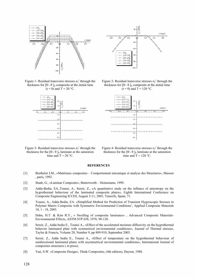
128
Figure 1- Residual transverse stresses σYr through the
thickness for [θ/- θ ]S composite at the initial time (t = 0) and T = 20 °C.
Figure 2- Residual transverse stresses σYr through the
thickness for [θ/- θ ]S composite at the initial time (t = 0) and T = 120 °C.
Figure 3- Residual transverse stresses σYr through the
thickness for the [θ/- θ ]S laminate at the saturation time and T = 20 °C.
Figure 4- Residual transverse stresses σYr through the
thickness for the [θ/- θ ]S laminate at the saturation time and T = 120 °C.
REFERENCES
[1] Berthelot J.M., «Matériaux composites – Comportement mécanique et analyse des Structures», Masson , paris, 1992.
[2] Staab, G., «Laminar Composite», Butterworth – Heinemann, 1999.
[3] Adda-Bedia, EA.,Tounsi, A., Sereir, Z., «A quantitative study on the influnce of anisotropy on the hygrothermal behaviour of the laminated composite plates», Eighth International Conference on Composite Engineering ICCE8, August 5-11, 2001, Tenerife, Spain, 71.
[4] Tounsi, A., Adda-Bedia, EA. «Simplified Method for Prediction of Transient Hygroscopic Stresses in Polymer Matrix Composite with Symmetric Environmental Conditions’, Applied Composite Materials 10, 1 - 18, 2003.
[5] Hahn, H.T. & Kim R.Y., « Swelling of composite laminates» , Advanced Composite Materials-Environmental Effects, ASTM STP 658, 1978, 98-120.
[6] Sereir, Z., Adda bedia E., Tounsi A., «Effect of the accelerated moisture diffusivity on the hygrothermal behavior laminated plate with symmetrical environmental conditions», Journal of Thermal stresses, Taylor & Francis, Volume 28, Number 9, pp 889-910, September 2005.
[7] Sereir, Z., Adda bedia E., Tounsi A., «Effect of temperature on the hygrothermal behaviour of unidirectional laminated plates with asymmetrical environmental conditions», International Journal of composites structures ( in press).
[8] Tsai, S.W. «Composite Design», Think Composites, (4th edition), Dayton, 1988.

129
SESSION 8 – TESTING
Chair: Prof. Josep Costa University of Girona, Spain
Tuesday 11th April 16:20 – 18:00

130
NOISE REDUCTION OF STRAIN MAPPING DATA AND IDENTIFICATION OF DAMAGE INITIATION OF CARBON-EPOXY TRIAXIAL BRAIDED COMPOSITE
Dmitry Ivanov, Stepan Lomov, Ignaas Verpoest, Alexander Zisman Katholieke Universiteit Leuven
Kasteelpark Arenberg, 44 B-3001 Leuven (Heverlee) Belgium
ABSTRACT
Carbon epoxy triaxial braided composite is studied. The focus of the work is meso analysis (scale level of the fabric unit cell) of composite deformation and failure. Since the unit cell of the composite is quite large (14 mm) the surface strain measurement give a sound base for meso strain distribution study. The investigation has been done by means of digital speckle photography (strain mapping) provided by Aramis system.
The strains have been measured in uniaxial tension tests. Load has been applied to the direction of inlay yarn, braiding yarns and to the cross-direction (normal to inlay) (Figure 1). The width of the specimens corresponds to the double unit cells size in the machine and cross directions. Specimens were covered with fine black and white spots for the sake of better image recognition. Facet grid is of rectangular pattern with the size of the facet about 1 mm. Applied quasi static load was displacement controlled. Digital pictures were produced with the step of 0.033 % of macro deformation.
Linear elastic behaviour was expected up to a certain level of load. Non-elastic deformations relate to matrix crack occurrence. Thus one can expect of the strain fields in the linear regions: 1) Proportionality. Strain field on each load step should be proportional to the applied strain. 2) Periodicity. The periodicity is expected at least in direction of loading (the studied region covers only two unit cells in width, hence boundary effect can play a role). 3) Smoothness. A thin layer of matrix covers all the surface of the composite. Hence there is no inner interface boundary, which would lead to sudden changes in the fields.
The fields directly obtained from experiments hardly suit the requirements (Figure 2). It has been concluded that deviation from a smooth proportional periodical fields is caused by a noise of the measurements. Negative values of the strains (those in the direction of loading), calculated by the system, confirmed the assumption (Figure 3).
Figure 2- Relation between local strain at a point εloc and average (applied) strain εave (εloc- approximation by the least
square method)
Figure 3- Local normalised strain fields along a line in the direction of loading (MD) (1-
original field; 2- filtered field; 3- filtered and smoothed field; 4- a sinus function with the
period of the structure)
Relation between the local and average (applied) strain was considered for all the points of the studied zone. Any tendency of the curve (taken for a single point) is not clearly seen. The relation was approximated by the least square method, which reproduce an ideal case (error free) of linear elastic deformations. The deviation from the idealised straight line was analysed for all the studied points statistically. It occurred that the distribution of the noise is normal with the standard deviation similar for all initial load steps. Thus the linear regression of local-applied strain curve might be used as filtering of the noise.
Additional smoothing of the strain fields is used since the filtered fields still present a ragged character. It is based on the local approximation around a considered point. The value of a plane approximating strain at
Figure 1- Triaxial braid and its
WiseTex model.

131
neighbourhood of a point is taken instead of the original value. The comparison of initial and processed fields is given on the Figure 4. The minimum and maximum values of filtered and smoothed field present good coincidence with finite element modelling of the process. Periodicity of the studied field is further analysed by means of Fourier transform.
Reduction of the noise can also be achieved by gradient matrix differentiation of displacement fields. The method is based on differentiation of discrete displacement data around a considered point by a specifically defined gradient matrix. It is readily recalculated for whichever number and arrangement of involved points, thus ensuring the best compromise between the structure resolution and accuracy of derived strain field.
Figure 4- Normalised strain fields in the direction of loading (MD). (a) Initial field at applied strain 0.1%; (b) Filtered field; (c) Filtered and smoothed field.
Apart from the filtering, analysis of the noise allows identification of the on-set of damage, which causes deviations from the linearity of behaviour. In order to define the range of pure elastic deformations the dependence of relative error on the average strain has been calculated for 16 points placed in a square grid (Figure 5). The curves are accompanied by the subjection of the standard deviation of the relative error to the average strain.
As it is seen the error tends to have a convergence to zero up to a certain level. However it changes at the point of the transition strain. Several curves come out of the “probable” value range and stay there while the load is increasing. The dependence has clearly bilinear character. It leads to the conclusion on the reason of such strain disturbance. Apparently it is caused by a sudden crack occurrence. The crack keeps its size with the load increase up to a next critical deformation level.
The determination of transition strain is supported by acoustic emission measurements: at 0.3% of applied deformation (machine direction) accumulative energy of the emission give a sudden change. Thus the approximating of strain measurements over the load steps presents reasonable filtering technique, where the zone of approximation is naturally defined by relative error considerations. The filtered strain field doesn’t possess negative values.
To sum up, statistical features of the strain-mapping field have been investigated. Filtering technique has been proposed based on a linear regression of data over the load steps. The filtering in combination with area smoothing gives quite a reasonable estimation of the studied “error-free” strain. The initiation of damage has been identified by means of statistical study of the strain fields.
Figure 5- Relative error of the measurements for 16 points placed in square grid.
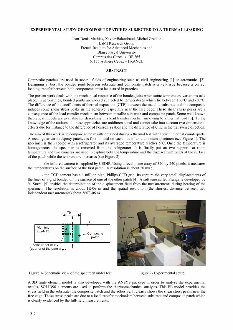
132
EXPERIMENTAL STUDY OF COMPOSITE PATCHES SUBJECTED TO A THERMAL LOADING
Jean-Denis Mathias, Xavier Balandraud, Michel Grédiac LaMI Research Group
French Institute for Advanced Mechanics and Blaise Pascal University
Campus des Cézeaux, BP 265 63175 Aubière Cedex – FRANCE
ABSTRACT
Composite patches are used in several fields of engineering such as civil engineering [1] or aeronautics [2]. Designing at best the bonded joint between substrate and composite patch is a key-issue because a correct loading transfer between both components must be insured in practice.
The present work deals with the mechanical response of the bonded joint when some temperature variations take place. In aeronautics, bonded joints are indeed subjected to temperatures which lie between 100°C and -50°C. The difference of the coefficients of thermal expansion (CTE) between the metallic substrate and the composite induces some shear stress peaks in the adhesive, especially near the free edge. These shear stress peaks are a consequence of the load transfer mechanism between metallic substrate and composite patch. Some well known theoretical models are available for describing this load transfer mechanism owing to a thermal load [3]. To the knowledge of the authors, all these approaches are unidimensional and cannot take into account two-dimensional effects due for instance to the difference of Poisson’s ratios and the difference of CTE in the transverse direction.
The aim of this work is to compare some results obtained during a thermal test with their numerical counterparts. A rectangular carbon/epoxy patches is first bonded on each side of an aluminium specimen (see Figure 1). The specimen is then cooled with a refrigerator and its averaged temperature reaches 5°C. Once the temperature is homogeneous, the specimen is removed from the refrigerator. It is finally put on two supports at room temperature and two cameras are used to capture both the temperature and the displacement fields at the surface of the patch while the temperature increases (see Figure 2):
- the infrared camera is supplied by CEDIP. Using a focal plane array of 320 by 240 pixels, it measures the temperatures on the surface of the first patch. Its resolution is about 20 mK;
- the CCD camera has a 1 million pixel Philips CCD grid. Its capture the very small displacements of the lines of a grid bonded on the surface of one of the other patch [4]. A software called Frangyne developed by Y. Surrel [5] enables the determination of the displacement field from the measurements during heating of the specimen. The resolution is about 1E-06 m and the spatial resolution (the shortest distance between two independent measurements) about 360E-06 m.
Figure 1- Schematic view of the specimen under test Figure 2- Experimental setup
A 3D finite element model is also developed with the ANSYS package in order to analyse the experimental results. SOLID90 elements are used to perform the thermomechanical analysis. This FE model provides the stress field in the substrate, the composite patch and the adhesive. It clearly shows the shear stress peaks near the free edge. These stress peaks are due to a load transfer mechanism between substrate and composite patch which is clearly evidenced by the full-field measurements.

133
Typical examples of measured temperature variations as well as calculated and measured displacement fields are shown in Figure 3, 4 and 5 respectively. They illustrate the temperature and displacement gradients which take place while heating of the specimen.
Figure 3- Temperature difference at the surface of the specimen (one quarter of the patch)
Figure 4- Numerical displacement field (one quarter of the patch)
Figure 5- Experimental displacement field (one quarter of the patch)
The main features of the experimental/numerical comparison will be developed in the paper. Various results in terms of length of the transfer zone, amplitude of the shear stress peak, shape of the patch or comparison between theoretical unidirectional models and numerical bidirectional models will be discussed in the presentation.
REFERENCES
[1] Hollaway, L., Leerning, M., "Strengthening of reinforced concrete structures using externally-bonded FRP composites in structural and civil engineering". Cambridge: Woodhead PublishingLtd, 1999.
[2] Baker, A.A., "Repair of Cracked or Defective Metallic Aircraft Components with Advanced Fibre Composites - an Overview of Australian Work", Composite Structures, Vol. 2, pp. 153-164, 1984.
[3] Duong, C.N., Yu, J., "An analytical estimate of thermal effects in a composite bonded repair: plane stress analysis", International Journal of Solids and Structures, Vol. 39, pp. 1003-1014, 2002.
[4] Piro J.L., Grédiac M., "Producing and transferring low-spatial-frequency grids for measuring displacement fields with moiré and grid methods", Experimental Techniques, Society for Experimental Mechanics, Vol. 28, No. 4, 2004.
[5] Surrel, Y., "Moiré and grid methods: a ‘signal processing’ approach". Photomechanics, pp. 118-127, 1994.

134
STIFFNESS AND FAILURE BEHAVIOUR OF FOLDED SANDWICH CORES UNDER COMBINED TRANSVERSE SHEAR AND COMPRESSION
D. Hartung, M. Kintscher, L. Kärger, A. Wetzel DLR Institute of Composite Structures and Adaptive Systems
Lilienthalplatz 7 38108 Braunschweig, Germany
ABSTRACT
Compared to monolithic composite structures, a sandwich structure consisting of a lightweight core and CFRP face sheets enables an even more weight efficient design. Furthermore, the outer face sheet serves as an impact detector and the core provides acoustic and heat insulation. However, the application of sandwich structures in the aircraft industry is restricted by their sensitiveness against out-of-plane loads, like low and high velocity impacts. As a consequence, considerable stiffness reduction occurs resulting from material degradation in the core and face sheets. Therefore, the out-of-plane stiffness and progressive failure behaviour of sandwich structures is of particular importance for the impact resistance. Concerning this problem, the Finite Element design tool CODAC was developed to analyse the impact behaviour and the residual strength of sandwich structures. The core stiffness and strengths as well as the nonlinear behaviour of the damaged core is described by homogenised material models. In order to develop and validate the applied models, experimental impact and compression after impact tests are used. Moreover, quasi-static tests are needed to characterise the stiffness and failure behaviour of the applied materials.
Core materials of sandwich structures are characterised by high transverse shear and compression strength combined with low mass. Core structures of Nomex materials, like honeycombs and folded structures, show a high potential in this regard and have good mechanical properties. In order to suitably describe the failure behaviour of these core structures, experimental tests under combined loading of transverse shear and compression were conducted. Based on the measured strength values, appropriate failure criteria for honeycomb and folded structure cores were deduced. The stiffness behaviour of the intact core structures under combined loading as well as the crushing behaviour of the damaged core was examined and analysed. Furthermore, the performance regarding damage resistance was compared between honeycomb and folded cores.
Figure 1- Test facility with double-core specimen under combined shear and compression loading.

135
ON ASPECTS OF NON-LINEAR BENDING BEHAVIOUR OF A WIND-TURBINE BLADE UNDER FULL-SCALE TESTING
F.M. Jensen1, P.M. Weaver2, L.S. Cecchini2, H. Stang3 1Department of Wind Energy – Risoe National Laboratory, P.O. Box 49 – Roskilde, Denmark
2Department of Aerospace Engineering – University of Bristol – Bristol, UK 3Department of Civil Engineering-Technical University of Denmark – Lyngby, Denmark
KEYWORDS: Full-Scale testing, wind turbine blades, non-linear finite element analysis, failure mechanism, Brazier effect, anti-clastic effect, longitudinal bending
INTRODUCTION
A full-scale 34 m composite wind-turbine blade was tested to failure under flap-wise loading as shown in Figure 1. Strain and displacement measurements were recorded throughout the loading history. Different non-linear bending responses in the load carrying cap were observed during the full-scale test. These behaviours are simulated in FE and explained in this paper. Particular focus is put on the bending behaviour in the 8.5-17m segment. An explanation of transverse strain measurements is also explained in the full paper.
The work is a continuation of work presented in [1] where local deflections were observed and numerically simulated using a sub-model. This detailed sub-model included solid elements in the webs and spar caps. The boundary conditions in this sub-model were extracted from the global finite element analysis of the blade.
Figure 1- Full-Scale Test – Flap wise loading Figure 2- Blade with a load carrying main spar
EXPERIMENTAL TEST AND NUMERICAL MODELLING
Longitudinal strains of upper spar cap and outer skin were measured at five locations chordwise in the 8.5-17m segment. Different bending responses are observed, see Figure 2.

136
Figure 3- Strain on the outer surface compared with strain inside the box in 8.5m and 17.0m.
The transverse strains in 10.3m from the root were measured and are shown in figure 4. The non-linear strain responses seen in figure 4 are caused by the Brazier effect [2+3].
Figure 4- Transverse strain measurement of section 10.3m
Figure 5- Rib/bulkhead to prevent crushing pressure
CONCLUDING REMARKS
Longitudinal and transverse strain values measured at the full-scale test have shown that bending occurs in cap due to Brazier and Anticlastic effects. The transverse and longitudinal strains can be eliminated if ribs are implemented in the load-carrying box, see figure 5.
REMARKS
[1] Jensen, F.M., B.G. Falzon, J. Ankersen, H. Stang “Structural testing and numerical simulation of a 34m composite wind turbine blade”, Composite Structures (January 2006).
[2] Brazier, L.G. “The flexure of thin cylindrical shells and other ‘thin’ sections”, Late of the Royal Aircraft Establishment. Reports and Memoranda, No. 1081 (M.49), 1926, pp. 1-30.
[3] Cecchini L. S. and Weaver, P. M. “The Brazier effect in multi-bay aerofoil sections” 45th AIAA,ASCE,ASME,AHS SDM conference, Palm Springs, USA, April 2004.

137
SESSION 9 – SCALE EFFECTS AND JOINTS
Chair: Prof. Michael Wisnom University of Bristol, United Kingdom
Wednesday 12th April 08:30 – 10:35

138
INTERLAMINAR DEFORMATION ALONG THE CYLINDRICAL SURFACE OF A HOLE IN LAMINATED COMPOSITES
David Mollenhauer Air Force Research Laboratory, Dayton, OH, USA
ABSTRACT
The deformation along cylindrical surfaces of holes in tensile-loaded specimens was measured using Moiré interferometry techniques. The techniques were developed and validated using an isotropic, homogeneous aluminum specimen. Two composite tensile specimens, fabricated from IM7/5250-4 pre-preg with ply lay-ups of [0°4/90°4]3s and [+30°2/-30°2/90°4]3s, were then examined with Moiré. Circumferential and thickness direction displacement fringe patterns (each 3° wide) were assembled into 90°-wide mosaics around the hole periphery for both composite specimens. Distributions of strain were calculated with high confidence on a sub-ply basis at selected angular locations. The measured strain behavior was complex. Ply-by-ply trends were revealed. Large ply-related variations in the circumferential strain were observed at certain angular locations around the periphery of the holes in both composites. Extremely large ply-by-ply variations of the shear strain were also documented in both composites. Peak values of shear strain approached 30 times the applied far-field axial strain. Residual viscoelastic shearing strains were recorded in regions of large load-induced shearing strains. Large ply-group related variations in the thickness direction strain were observed in the [+30°2/-30°2/90°4]3s specimen. An important large-scale trend was observed in which the thickness direction strain tended to be more tensile near the outside faces of the laminate than near the mid-ply region. These experimental results were compared with predictions made using a unique spline-based numerical method that has been shown to have great fidelity. Comparisons between the experimental and analytical techniques were extremely close.

139
STRUCTURAL RESPONSE ANALYSES OF VESTAS V52 WIND TURBINE BLADE
Lars Chr. T. Overgaarda, P.P. Camanhob and Erik Lunda aDMS, Institute of Mechanical Engineering, Aalborg University,
Pontoppidanstraede 101, DK-9220 Aalborg East, Denmark bDEMEGI, Faculdade de Engenharia, Universidade do Porto,
Rua Dr. Roberto Frias, 4200-465, Porto, Protugal
Keywords: Composite material; Structural instability; Wind turbine blade; Geometrically nonlinear problem;Continuum-based element; Natural assumed strains; Cohesive zone model.
ABSTRACT
In a wide range within the application of composite and sandwich materials structural instability phenomena are present, which under some conditions can be critical for the integrity of the structure. The suction side of the aerofoil in a wind turbine blade during operation is loaded considerable in compression, which can trigger instability or local buckling due to geometric and/or material-wise imperfection fields. The consequence of local buckling is delamination as a failure mechanism, which ultimately results in a progressive collapse of the structure.
Thus the driving design parameter within the wind turbine blade industry has shifted from fatigue issues to structural instability as the blades become larger and new materials are taken into use.
For this reason there is a general consensus in the industry that this issue must be addressed. Hence new design rules and methods must be addressed in order to estimate under which conditions the structural integrity of the blade is compromised.
The objectives of this work are geometric nonlinear structural response analyses derived from a degenerated finite shell element with a linear material law formulation and a continuum-based shell element with a cohesive zone formulation, initial derived in [1, 2] and further developed by [3-6], of a 25-meters wind turbine blade from a V52 wind turbine manufactured by Vestas Wind Systems A/S.
A geometrically nonlinear analysis is performed for predicting the failure of the blade due to local buckling on the suction side of the airfoil, and the objective is to compare the shell element solutions, linear material law and cohesive zone formulation, with the static test results preformed on the wind turbine blade.
The continuum-based shell element model is to be incorporated in the in-house finite element program MUltidisciplinary Synthesis Tool (MUST) developed at Aalborg University, see [7], and the finite element model based on the degenerated shell element is being generated using Patran Command Language (PLC) in a blade builder program using MSC.Patran and MSC.LaminateModeler and MSC.Marc as numerical solver.
The mixed-mode decohesive element for analysis of the progressive delamination in the wind turbine blade is formulated using a continuum based three-dimensional shell element for laminated structures, see [8]. The Assumed Natural Strain (ANS) interpolation in the transverse shear strain and thickness strains practically makes the element locking-free and capable of shell and cohesive zone modelling.
Full scale experiments of the static collapse of the wind turbine blade have been performed, see [9], and are used for comparison with the predictive models in order to either confirm or reject hypotheses set forth during the evaluation of the experimental data of the flap-wise static test. Experimental data includes local strain and displacement values together with global deflections and load multipliers recorded during testing. Additionally an acoustic emission system is employed in order to triangulate high energy bursts at crack initiation and propagation.
The two chosen element formulations are both capable of predicting global values as the equilibrium path and deformation together with the local strain and stress state in the individual layers of the laminated composite structure. However, if a sufficient fine discretization through the thickness is employed with the continuum element, then a correct description of interlaminar shear stresses and normal stresses is obtainable, whereas the degenerated element calculates the interlaminar stresses by post-processing derived from the equilibrium equations.
It is expected that the two element formulations will agree until structural instability, where the decohesive zone model will show that the primary load-carrying structure in the wind turbine blade will deform in a local buckling shape mode, which will produce progressive delamination in the adjacent corners between the flange and web of the composite structure.

140
STATUS OF WORK
The degenerated finite shell element model is generated using PCL in a blade builder program using MSC.Patran and MSC.LaminateModeler and the geometrically nonlinear analysis is performed using MSC.Marc. The continuumbased shell element formulation with a cohesive zone model is still to be implemented and solved in the in-house finite element program MUST.
REFERENCES
[1] Y. Mi, M.A. Crisfeld, G.A.O. Davies, and H.B. Hellweg., “Progressive Delamination using Interface Elements” Journal of Composite Materials, 32(14), pp.1246-1272, 1998.
[2] G. Alfano and M.A. Crisfeld., “Finite Element Interface Models for the Delamination Analysis of Laminated Composites: Mechanical and Computational Issues” International Journal for Numerical Methods in Engineering, 50(7), pp.1701-1736, 2001.
[3] Camanho, P.P., Dávila, C.G., “Numerical Simulation of Delamination Growth in Composite Materials” NASA/Techical Report TR-2001-211041, August 2001.
[4] Camanho, P.P., Dávila, C.G., “Mixed-Mode Decohesion Finite Elements for the Simulation of Delamination in Composite Materials” NASA/Techical Memorandum TM-2002-211737, June 2002.
[5] Camanho, P.P., Dávila, C.G., de Moura, M.F., “Numerical simulation of mixed-mode progressive delamination in composite materials” Journal of Composite Materials, 37 (16), pp. 1415-1438, 2003.
[6] Turon, A., Dávila, C.G., Camanho, P.P., Costa, J., “An Engineering Solution for using Coarse Meshes in the Simulation of Delamination With Cohesive Zone Models” NASA/Techical Memorandum TM-2005-213547, March 2005.
[7] The MUltidisciplinary Synthesis Tool (MUST), developed at Aalborg University, http://www.ime.auc.dk/research/design/fluidstructure/MUST/.
[8] Klinkel, S., Gruttmann, F., Wagner, W., “A continuum based three-dimensional shell element for laminated structures” Computers & Structures, 71, pp. 43-62, 1999.
Christian Leegaard Thomsen et al.: V52 statisk styrke (in Danish). Risø-I-1980(DA), Forskningscenter Risø, Roskilde, April 2003.
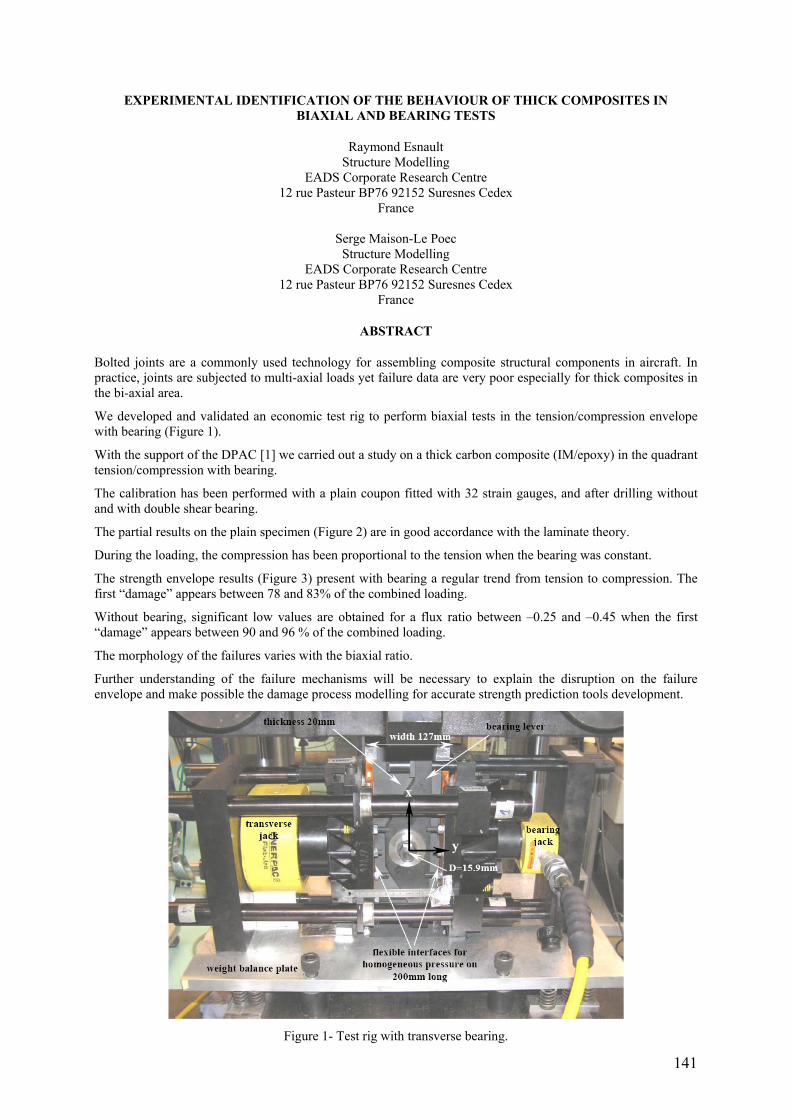
141
EXPERIMENTAL IDENTIFICATION OF THE BEHAVIOUR OF THICK COMPOSITES IN BIAXIAL AND BEARING TESTS
Raymond Esnault Structure Modelling
EADS Corporate Research Centre 12 rue Pasteur BP76 92152 Suresnes Cedex
France
Serge Maison-Le Poec Structure Modelling
EADS Corporate Research Centre 12 rue Pasteur BP76 92152 Suresnes Cedex
France
ABSTRACT
Bolted joints are a commonly used technology for assembling composite structural components in aircraft. In practice, joints are subjected to multi-axial loads yet failure data are very poor especially for thick composites in the bi-axial area.
We developed and validated an economic test rig to perform biaxial tests in the tension/compression envelope with bearing (Figure 1).
With the support of the DPAC [1] we carried out a study on a thick carbon composite (IM/epoxy) in the quadrant tension/compression with bearing.
The calibration has been performed with a plain coupon fitted with 32 strain gauges, and after drilling without and with double shear bearing.
The partial results on the plain specimen (Figure 2) are in good accordance with the laminate theory.
During the loading, the compression has been proportional to the tension when the bearing was constant.
The strength envelope results (Figure 3) present with bearing a regular trend from tension to compression. The first “damage” appears between 78 and 83% of the combined loading.
Without bearing, significant low values are obtained for a flux ratio between –0.25 and –0.45 when the first “damage” appears between 90 and 96 % of the combined loading.
The morphology of the failures varies with the biaxial ratio.
Further understanding of the failure mechanisms will be necessary to explain the disruption on the failure envelope and make possible the damage process modelling for accurate strength prediction tools development.
Figure 1- Test rig with transverse bearing.
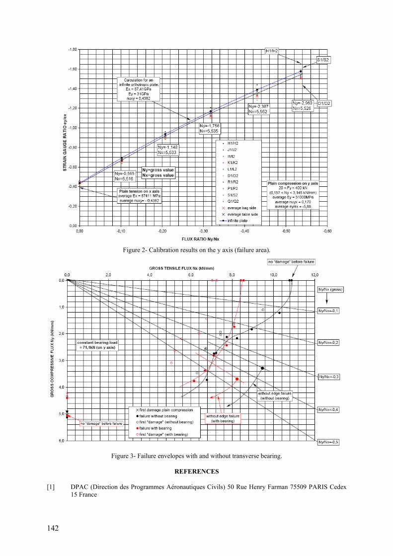
142
Figure 2- Calibration results on the y axis (failure area).
Figure 3- Failure envelopes with and without transverse bearing.
REFERENCES
[1] DPAC (Direction des Programmes Aéronautiques Civils) 50 Rue Henry Farman 75509 PARIS Cedex 15 France

143
VALIDATION OF FEA PREDICTIONS OF BONDED AND BOLTED T-JOINTS
W Broughton, L Crocker, M Gower and R Shaw Engineering and Process Control Division
National Physical Laboratory Teddington, Middlesex
TW11 0LW, UK
ABSTRACT
Finite element analysis (FEA) studies have been carried out on bonded and bolted T-joints of similar geometry in order to predict local and global deformation, and failure load and failure location within these components. Strain distributions around stress concentrators in bonded and bolted joint configurations, and within the adhesive of the bonded T-joints have been determined using numerical analysis. A series of simulated experiments using FEA have been conducted on both 2014 aluminium alloy and glass fibre-reinforced plastic (GRP) T-joint configurations for this purpose (see Figure 1). The T-joints were subjected to direct tension, lateral tension and 45° (to horizontal) tension loads.
The FEA results are compared with experimental data. Global deformation was measured using linear voltage displacement transducers (LVDTs), whilst digital image correlation (DIC) and strain gauges were used to monitor localised strains (Figure 1). Strain gauges (Figure 2) were strategically located in the vicinity of key features in order to measure localised strain and to monitor the onset of localised damage. The exponent Drucker-Prager materials model was used to characterise deformation behaviour of the rubber-toughened epoxy adhesives used for bonding the T-joints. Experimental and predicted results were in reasonable agreement for the two test geometries (Tables 1 and 2). The FEA results provide further evidence that the combination of a new cavitation model, developed at NPL, and the hydrostatic stress yield criterion can be used to predict deformation, failure load and failure location within joints bonded with rubber-toughened epoxy adhesives. Closed form solutions were also derived to predict joint stiffness for the basic T-joint configurations and loading modes. Good agreement was obtained between the closed form solutions and experimental results.
FEA of lateral loaded GRP T-joint Direct tension loaded aluminium T-joint
Figure 1- Bolted aluminium T-joint (with strain gauges)
Failed GRP T-joint Failed aluminium T-joint
Figure 2- Failure of direct-tension loaded bolted T-joints

144
Table 1- Strength and Stiffness for Direct and Transverse Tension Loading of Bonded T-joints (* FEA failed to converge)
Experiment FEA/Analytical Solution Configuration PMAX
(kN) Stiffness (kN/mm)
PMAX (kN)
Stiffness (kN/mm)
Direct Aluminium GRP
30.76±3.54 14.27±4.53
58.58±4.38 17.15±2.38
31.16 15.44
56.80/59.88 16.05/15.41
Transverse Alluminium GRP
13.60±0.51 6.27±1.54
3.88±0.38 1.25±0.11
7.41* 5.13*
3.74/3.90 1.06/1.00
Table 2- Structural Properties for Direct Tension Loading of Bolted T-joints
Experiment FEA/Analytical Solution Configuration P (kN) S (kN/mm) P (kN) S (kN/mm)
Aluminium Ultimate Gross Yielding
79.75±0.67 48.43±3.01
10.93±0.48
96.13 49.20
14.72/9.82
GRP Ultimate Localised Yielding
20.47±3.79 ~10.00
2.94
18.53 10.52
2.50/3.31

145
POSTER SESSION 5
Wednesday 12th April 10:35 – 11:15

146
INFLUENCE OF THE SPECIMEN SIZE ON THE R-CURVE BEHAVIOUR IN WOOD
N. Dourado1, S. Morel2, M.F.S.F. de Moura3, G. Valentin2, J. Morais1 1CETAV/UTAD, Depart. de Engenharias, Quinta de Prados, 5000-911 Vila Real, Portugal 2LRBB, UMR 5103 (CNRS/INRA/Univ. Bx1), 69 route d'Arcachon, 33612 Cestas, France 3Fac. Engenharia da Universidade do Porto, R. Dr. Roberto Frias, 4200-465 Porto, Portugal
ABSTRACT
The concept of the R-curve was first introduced in 1958 by Irwin [1] and more clearly in 1961 by Kraft, Sullivan and Boyle [2], stating that crack growth resistance is not invariable but increases with the crack length da, frequently expressed through R=f(da). Experimental and theoretical investigations in materials that exhibit toughening behaviour have proved however, that the R-curve is not an intrinsic material property but depends on many factors. These include test specimen geometry [3], relative crack size [4], mode of loading [5], and specimen size [6]. To the authors knowledge the influence of the specimen size on the R-curve is not well understood in wood. As a result, experiments in spruce (Picea abies L.) have been conducted inducing fracture (Mode I) in geometrically similar Single-Edge-Notched composite beams in Three Point-Bending (SEN-TPB) (Figure 1), under displacement control. The experiments involved 6 series of specimens resulting in a size range of 1:12 (Table 1) and a span-to-depth (L/h) ratio fixed to 6. Fracture was chosen to occur in wood fracture system TL (Figure 1).
The experiments generated a total of 158 load-displacement curves (Figure 2) with initial stiffness Rexp(a0), ultimate load P)(0expaRu and corresponding load-point displacement δu values reported in Table 2 for each series. The results revealed that mean values of the initial stiffness, Rexp(a0), as well as the ultimate load, Pu, increase with the specimen size. Displacement values corresponding to the ultimate load Pu were found to increase with the specimen size h as well.
Figure 1- SEN-TPB specimen’s parts set up before bonding. Anatomic axis directions in wood: (L) Longitudinal,
(R) Radial and (T) Tangential. h: characteristic structure size. a0: initial crack length. b: thickness.
Table 1- Series and corresponding dimensions (in mm). h: Characteristic structure size, b: Specimen thickness, a0: extension of the initial crack notch. (Series h4 is the reference characteristic structure).
Series 3h h b a0 Span (L)
h1 840 280 80 140 1680
h2 630 210 60 105 1260
h3 420 140 40 70 840
h4 210 70 20 35 420
h5 105 35 10 17.50 210
h6 70 23.33 6.67 11.67 140
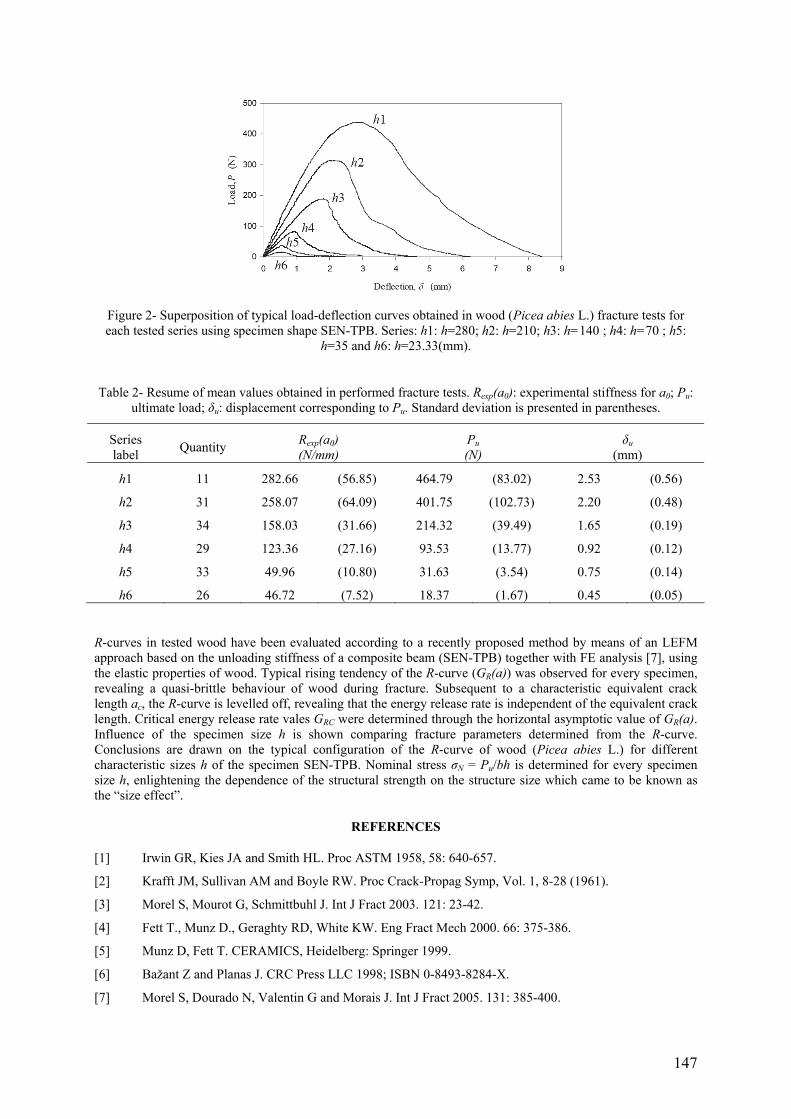
147
Figure 2- Superposition of typical load-deflection curves obtained in wood (Picea abies L.) fracture tests for each tested series using specimen shape SEN-TPB. Series: h1: h=280; h2: h=210; h3: h=140 ; h4: h=70 ; h5:
h=35 and h6: h=23.33(mm).
Table 2- Resume of mean values obtained in performed fracture tests. Rexp(a0): experimental stiffness for a0; Pu: ultimate load; δu: displacement corresponding to Pu. Standard deviation is presented in parentheses.
Series label Quantity Rexp(a0)
(N/mm) Pu (N)
δu (mm)
h1 11 282.66 (56.85) 464.79 (83.02) 2.53 (0.56)
h2 31 258.07 (64.09) 401.75 (102.73) 2.20 (0.48)
h3 34 158.03 (31.66) 214.32 (39.49) 1.65 (0.19)
h4 29 123.36 (27.16) 93.53 (13.77) 0.92 (0.12)
h5 33 49.96 (10.80) 31.63 (3.54) 0.75 (0.14)
h6 26 46.72 (7.52) 18.37 (1.67) 0.45 (0.05)
R-curves in tested wood have been evaluated according to a recently proposed method by means of an LEFM approach based on the unloading stiffness of a composite beam (SEN-TPB) together with FE analysis [7], using the elastic properties of wood. Typical rising tendency of the R-curve (GR(a)) was observed for every specimen, revealing a quasi-brittle behaviour of wood during fracture. Subsequent to a characteristic equivalent crack length ac, the R-curve is levelled off, revealing that the energy release rate is independent of the equivalent crack length. Critical energy release rate vales GRC were determined through the horizontal asymptotic value of GR(a). Influence of the specimen size h is shown comparing fracture parameters determined from the R-curve. Conclusions are drawn on the typical configuration of the R-curve of wood (Picea abies L.) for different characteristic sizes h of the specimen SEN-TPB. Nominal stress σN = Pu/bh is determined for every specimen size h, enlightening the dependence of the structural strength on the structure size which came to be known as the “size effect”.
REFERENCES
[1] Irwin GR, Kies JA and Smith HL. Proc ASTM 1958, 58: 640-657.
[2] Krafft JM, Sullivan AM and Boyle RW. Proc Crack-Propag Symp, Vol. 1, 8-28 (1961).
[3] Morel S, Mourot G, Schmittbuhl J. Int J Fract 2003. 121: 23-42.
[4] Fett T., Munz D., Geraghty RD, White KW. Eng Fract Mech 2000. 66: 375-386.
[5] Munz D, Fett T. CERAMICS, Heidelberg: Springer 1999.
[6] Bažant Z and Planas J. CRC Press LLC 1998; ISBN 0-8493-8284-X.
[7] Morel S, Dourado N, Valentin G and Morais J. Int J Fract 2005. 131: 385-400.

148
THERMAL STRESSES IN UNSYMMETRIC CROSS-PLY COMPOSITE BEAMS
Faustino Mujika, Neftalí Carbajal, Jesús María Romera, Ainhoa Arrese Department of Mechanical Engineering-Polytechnical University College,
Plaza de Europa 1, 20018 Donostia-San Sebastian University of the Basque Country
Spain
ABSTRACT
The difference between the thermoelastic properties of longitudinal (0º) and transverse (90º) plies causes bending curvatures and bending stresses in an unsymmetric cross-ply composite laminate [1]. If the longitudinal direction of the laminate is much greater than its width, it can be considered as a beam and only the stresses in longitudinal direction are considered. Figure 1 shows the cross section of an unsymmetric cross-ply beam.
Figure 1- Cross section of an unsymmetric cross-ply composite beam.
Under the assumptions of classical beam theory, the variation of longitudinal strains along the cross-section is linear:
yερ
= (1)
where ρ is the radius of curvature of the neutral axis (N.A.). The coordinate y has its origin in the neutral axis and it is positive downwards. Considering only thermal effects in the longitudinal direction of the beam, normal strain is:
TEσε α= + Δ (2)
where E is the elastic modulus, α is the coefficient of thermal expansion and ΔT is the variation of temperature. From Equations (1) and (2) the normal stress σ is:
yE Tσ αρ
⎛ ⎞⎟⎜= − Δ ⎟⎜ ⎟⎜⎝ ⎠ (3)
Considering only thermal effects, the resultant of the normal stresses is 0:
0 0T L
T T T L L LA A A
y ydA E T dA E T dAσ α αρ ρ
⎛ ⎞ ⎛ ⎞⎟ ⎟⎜ ⎜= ⇒ − Δ + − Δ =⎟ ⎟⎜ ⎜⎟ ⎟⎜ ⎜⎝ ⎠ ⎝ ⎠∫ ∫ ∫ (4)
Defining the ratio between the elastic moduli as L
T
EE
λ = TLEE=λ, the curvature of the neutral surface from
Equation (4) is:
( )( )
1 T T T T
T T L L
T A Ay A y Aα λα
ρ λΔ +=
+ (5)
where yT and yL are the distances from the centroids GT and GL according to Figure 1 and AT and AL are the respective areas. Imposing the condition that the bending moment is 0:
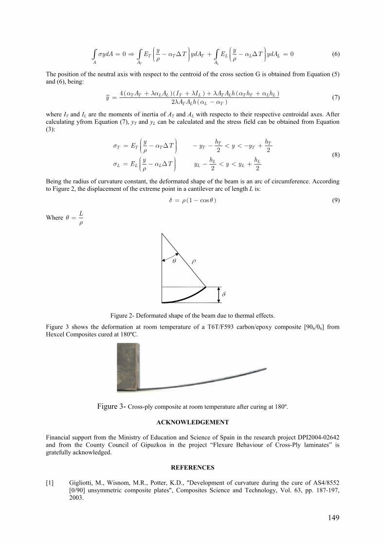
149
0 0T L
T T T L L LA A A
y yydA E T ydA E T ydAσ α αρ ρ
⎛ ⎞ ⎛ ⎞⎟ ⎟⎜ ⎜= ⇒ − Δ + − Δ =⎟ ⎟⎜ ⎜⎟ ⎟⎜ ⎜⎝ ⎠ ⎝ ⎠∫ ∫ ∫ (6)
The position of the neutral axis with respect to the centroid of the cross section G is obtained from Equation (5) and (6), being:
( )( ) ( )( )
42
T T L L T L T L T T L L
T L L T
A A I I A A h h hy
A A hα λα λ λ α α
λ α α+ + + +=
− (7)
where IT and IL are the moments of inertia of AT and AL with respecto to their respective centroidal axes. After calculating yfrom Equation (7), yT and yL can be calculated and the stress field can be obtained from Equation (3):
2 2
2 2
T TT T T T T
L LL L L L L
y h hE T y y y
y h hE T y y y
σ αρ
σ αρ
⎛ ⎞⎟⎜= − Δ − − < < − +⎟⎜ ⎟⎜⎝ ⎠⎛ ⎞⎟⎜= − Δ − < < +⎟⎜ ⎟⎜⎝ ⎠
(8)
Being the radius of curvature constant, the deformated shape of the beam is an arc of circumference. According to Figure 2, the displacement of the extreme point in a cantilever arc of length L is:
( )1 cosδ ρ θ= − (9)
Where Lθρ
=
Figure 2- Deformated shape of the beam due to thermal effects.
Figure 3 shows the deformation at room temperature of a T6T/F593 carbon/epoxy composite [906/06] from Hexcel Composites cured at 180ºC.
Figure 3- Cross-ply composite at room temperature after curing at 180º.
ACKNOWLEDGEMENT
Financial support from the Ministry of Education and Science of Spain in the research project DPI2004-02642 and from the County Council of Gipuzkoa in the project “Flexure Behaviour of Cross-Ply laminates” is gratefully acknowledged.
REFERENCES
[1] Gigliotti, M., Wisnom, M.R., Potter, K.D., "Development of curvature during the cure of AS4/8552 [0/90] unsymmetric composite plates", Composites Science and Technology, Vol. 63, pp. 187-197, 2003.

150
EXPERIMENTAL TESTING OF A NATURAL CORK-BASED COMPOSITE – SHEAR BEHAVIOUR COMPARISON WITH OTHER MATERIALS FOR SANDWICH APPLICATIONS
Arlindo Silva1, João Lopes1, Pedro Almeida2, Luis Reis1, Marco Leite3 1ICEMS, Instituto Superior Técnico, Lisboa
2EST-IPS – Escola Superior de Tecnologia de Setúbal, Instituto Politécnico de Setúbal 3ESTA-IPT – Escola Superior de Tecnologia de Abrantes, Instituto Politécnico de Tomar
ABSTRACT
Sandwich structures are present in many of the current composite construction. Typical materials used for the core include polymer foams and aluminium or aramid paper honeycomb structures. For environmental reasons, it would be useful to consider using, for the sandwich core, a natural material, as long as it retains a structural strength and stiffness comparable with the classical materials, to name only a few important properties. Natural cork is an abundant material in Portugal, and the cork agglomerate industry is a well established one. Its density, thermal and mechanical properties make it suitable for application as a sandwich core material. To validate its usefulness for this application, a series of experimental tests must be performed, to determine the mechanical properties of these composite cork agglomerate materials. A previous work by the authors has established a term of comparison between natural cork agglomerate composites and other materials in compression [1]. Since the sandwich core acts primarily in shear, the current work presents an experimental study of a particulate core of natural cork agglomerates, tested in shear according to ASTM C273. The same study is carried out on polymer foam and aramid paper honeycomb. Both the foam and honeycomb are currently being used as core materials for aerospace sandwich structures.
Further studies will involve three and four point bending, impact and fatigue tests with composite sandwiches using different core materials. Comparisons will be made and conclusions will be drawn from the experimental tests, evaluating the usefulness of natural cork agglomerates as an alternative to the polymer foams and honeycombs in aerospace sandwich structures.
ACKNOWLEDGMENTS
The authors acknowledge the support from Corticeira Amorim Indústria, SA, for providing the raw materials for testing, as well as all the technical details necessary to test and evaluate the natural cork composites.
REFERENCES
[1] Leite, M., Lopes, J., Silva, A., Estudo Experimental e Analítico, em Compressão, de Diferentes Espumas para Aplicação em Construção Sandwich. 6º Congresso Nacional de Mecânica Experimental, Ponta Delgada, 27-29 Julho 2005.

151
MODELLING THE ELASTIC BEHAVIOUR OF COMPOSITE MATERIALS WITH ASYMPTOTIC EXPANSION HOMOGENISATION
J.A. Oliveira, J. Pinho-da-Cruz, A. Andrade-Campos, F. Teixeira-Dias Departamento de Engenharia Mecânica, Universidade de Aveiro
Campus Universitário de Santiago 3810-193 Aveiro
Portugal
ABSTRACT
The demands put on the application of composite materials lead to a strong need for the modelling of the mechanical behaviour of structures built with such materials. On the work here presented, special focus is given to the modelling of aluminium matrix composites reinforced with spherical Silicon Carbide particles (AlSiCp). Some evaluations must be made in order to face the difficulties that arise both from the geometrical modelling and the computational weight of the simulations. A correct geometrical modelling must be associated to an accurate control of all the geometrical parameters involved such as reinforcement distributions and volume fractions. On the other hand, to model the whole structure with all microstructural details, the number of geometrical elements and of finite elements leads to a prohibitively high computational cost, even in linear elasticity problems.
The solutions to the referred limitations require some kind of problem optimisation. The approach assumed in the present case involves homogenisation procedures. Assuming that the material may be represented by a periodic micro-structure, the basic material properties can be considered upon the analysis of a representative unit-cell. The Asymptotic Expansion Homogenisation (AEH) is used to determine the average material properties for periodical structure composite materials, i.e. materials which representation may result from a tile arrangement of representative unit-cells [1, 2]. From the analysis of material property gradients within the unitcell, the method returns a homogenised elasticity matrix (Dh), representative of average, directional and distribution effects. Thus, a double-scale definition of the problem is needed. In this approach a microscale analysis is used to process the material properties. These properties are then used in the macroscale where the material is considered to be homogenous. The developed methodologies were additionally implemented with the use of parallel computation techniques (e.g. Message Passing Interface standard) in order to further limit the computational time.
The presented analyses are run on programs developed by the authors. Program SPHERECELL [3] is used to automatically generate the unit-cells, with control over the distribution of the reinforcement particles and their volume fractions. Continuity is always guaranteed using periodic unit-cell boundaries. The procedure SLAVERY specifies the periodicity constraints needed for the microscale finite element problem [4, 5] on both structured and non-structured meshes. This procedure works within the main program – 3DFRAN. The program computes the results for linear elasticity problems with AEH in uni- and multiprocessor (parallel) machines. METIS [6] is used for the domain decomposition in multiprocessor machines, dividing the problem in different data packages for an optimal distribution of processes.
However, the main objective of this work is to show the benefits of using tetrahedral meshes in multiscale problems, with the obvious gains in computational work. The use of this type of elements on unit-cell modelling is validated by comparison with a problem presented by Chung et al. [2] in which the microstructure is composed of an polymeric matrix composite reinforced with orthogonally organised continuous glass fibres (cf. Figures 1 and 2). On a second stage, the analysis moves to the referred aluminium matrix composites reinforced with spherical SiC particles. Subsequently, besides testing the stability of the automatic boundary node association and problem solving for non-regular meshes, the study is centred on the analysis of the influence of the geometrical properties of the microscale on the overall structure behaviour. This is done varying volume fractions and particle distributions. The elasticity matrixes (Dh) that result from the homogenisation procedure are analysed and compared, not only in terms of absolute numerical magnitudes but also in terms of value distributions. Conclusions are derived on both directional and numerical effects.

152
Figure 1- Multiscale analysis of a bending problem – equivalent stress plot.
Figure 2- Y-periodicity of the corrector displacements – illustration of the χ23 shear mode using 8 Unit-Cells with
a (a) hexahedral and (b) tetrahedral mesh.
REFERENCES
[1] Guedes, J.M., Kikuchi, N., “Preprocessing and postprocessing for materials based on the homogenization method with adaptive finite element methods”, Computer Methods in Applied Mechanical Engineering, Vol. 83, pp. 143-198, 1990.
[2] Chung, P.W., Tamma, K.K., Namburu, R.R., “Asymptotic expansion homogenization for heterogenous media: computational issues and applications”, Composites Part A, Vol. 32, pp. 1291-1301, 2001.
[3] Oliveira, J.A., Pinho-da-Cruz, J., Andrade-Campos, A., Teixeira-Dias, F., “On the modelling of representative unit-cell geometries with GiD”, GiD 2004 — 2nd Conference on Advances and Applications of GiD, Monografia CIMNE Vol. 88, pp. 181-184, 2004.
[4] Böhm, H.J., “A Short Introduction to basics aspects of continuum micromechanics”, CDL-FMDReport, IFLB, TU-Wien, Austria, 2003.
[5] Codina, R., Soto, O., “Computational of exterior normals and prescription of periodical conditions in finite element calculations”, Publication CIMNE Vol. 112, 1997.
[6] Karypis, G., Kumar, V., “METIS: a software package for partitioning unstructured graphs, partitioning meshes, and computing fill-reducing orderings of sparse matrices”, version 4.0, Technical Report, University of Minneapolis, USA, 1998.

153
TENSILE MECHANICAL PROPERTIES OF BI-LAYER STRUCTURE FOR SOLID OXIDE FUEL CELLS
Wang F H1,2, Helmuth Toftegaard2 and Peter V Hendriksen2 Bent F Sørensen2 (1Department of Engineering Mechanics, Northwestern Polytechnical University, Xi’an, P R
China,710072) (2Material Department,Riso National Laboratory, Denmark, DK 4000 )
ABSTRACT
In the case of SOFCs incorporating Ni-based anodes, damage of the bilayer ceramic structure usually takes place during the service of operation, it is important to concern about the failure behaviour of the anode and halfcell application in SOFC. But it is difficult to measure the tensile fracture stress due to brittle feature, so the Ring on Ring and bending approaches are usually used to test the failure stress. In this study, the strength of bilayer structure laminated ceramic was measured in tensile test, the residual stress in the bilayer at room temperature were estimated from their curvature, the residual stress in thin electrolyte (YSZ) is good agreement with the expected thermoelastic stress. The traditional tensile method was used to measure the failure stress of the brittle laminate. Several means to prepare the specimens after the tape cast were conducted in order to find the best way of obtaining specimens with highest possible strength: (a) punched before sintering, (b) laser cutting, (c) grinding after laser cutting. It is found that grinding the laser cutting surface can remove the cracks occurred during the laser cutting and gave the highest value among the ways. The tabs with holes for tensile test were bonded to the end of specimen and epoxy was added to corner between tabs and layer so as to reduce the stress concentration. The pretty results demonstrated that tensile test approach proposed in this paper is a good way for obtaining the strength of ceramic bilayer structure.
KEYWORDS: tensile test, ceramic bilayer, failure stress.

154
SOME APPLICATIONS ON THE CYCLIC EVOLUTION OF THE MOISTURE CONCENTRATION THROUGH A PLATE IN HYBRID COMPOSITE
Boualem N., Sereir Z. Faculté de Génie Mécanique, BP 1505 El M’naoeur , Université des sciences et de la technologie Mohamed
Boudiaf d’Oran, Algérie. Email: [email protected] Email: [email protected]
ABSTRACT
Composites knew a very significant evolution opposite traditional materials. This evolution is represented by the fast extension of the composite materials use in multiple industrial applications. The composite materials give indisputable industrial advantages [1, 2], from the point of view, design, manufacture, rigidity, weight, hygrothermal insulation… etc. Following many industrial applications, the users noted that the environment effect, such moisture and temperature, produce an inevitable deterioration of the mechanical characteristics [3] and a clear degradation during long years of service. This shows that it’s essential to obtain a good comprehension on composite materials exposed to severe and complex cyclic environmental conditions.
In this oblique, some works, illustrate the consequences of the environmental conditions on the composites with polymer matrices. Anisotropic three dimensional models of the Fickian diffusion were developed by C.H. Shen and G S. Springer [4]. These models were checked later with experimental data of moisture absorption produced by sea water for the graphite/epoxy and glass/epoxy [5]. In the same framework, a series of research was proposed by Adda Bedia [6, 7] for the analytical resolution of the moisture diffusion under the cyclic environmental conditions. These studies noted that the stacking sequences and the volume fraction of fibers influence incontestably on the diffusivity coefficient and the moisture contents. Rao [8] studies the effects of the sea water temperature and the environment relating humidity on the diffusion constants and the mass profit at the saturation time. A detailed characterization of the moisture absorption in the epoxy resins was reported by Crank [9] where the simultaneous effect of the temperature and the relative humidity on the diffusivity was studied. Of all quoted work, have can say that the polymeric matrices ensure a very good maintenance of fibers, but find enormous difficulties when they are exposed to environmental conditions such as the temperature and moisture. From all quoted works, we often envisage hybrid or sandwich composites. The hybrid composites are obtained by the combination between two materials or more to ensure, a better rigidity, or a suitable insulation against the extreme environmental conditions.
Within this framework we developed this work which belongs to a series of works recently presented [10 - 11]. The aim of this work is the calculation of the moisture concentration of the hybrid composite under cyclic environmental conditions (6 hours cycle) in order to backward the saturation time and to envisaging the additional lifespan for our plate. In the literature, very rare are the works which have studied this type of problems which are considered as extremely complicated.
Then to reach this aim, we presented some cases of a hybrid composite, on which, we varies gradually the thickness of each material opposite the other, but the total thickness of our plate is maintained constant. Therefore, the problem is reduced to make a progressive variation of the geometrical relationship (h1 and h2) between the two materials (AS/3501-5 and T300/5208) which form our hybrid composite (Figure 1). This procedure will enable us to find the best configuration which will offer favourable conditions to us, i.e., initially to push back the saturation time and secondly to reduce the maximum concentration reached during saturation time.
Figures 2, 3 and 4 represent the evolution of the moisture concentration from the initial time (6 days) until the saturation (9000 days), according to the thickness of the hybrid plate for the various applications; Figure 2 (h1 = 1.8 mm, h2 = 0.6 mm), Figure 3 (h1=1.2 mm, h2 =1.2 mm) and Figure 4 (h1 = 0.3 mm, h2 =2.1 mm). In these three figures, we observe an abrupt change of moisture concentration in the passage from the first to the second material; i.e. from h1 to h2. It is noticed that the maximum value at the saturation time (value plate) is higher when the thickness h2 is more important. Figure 4 shows us a phenomenon similar to the edge effect which was already studied by the Adda bedia [6, 7]. This phenomenon generates fluctuations on the moisture concentration in the vicinity of the edges of the hybrid plate.
CLEFS WORDS: Moisture concentration, Hybrid composites, Edge effect, cyclic evolution, Graphite/epoxy, diffusivity.
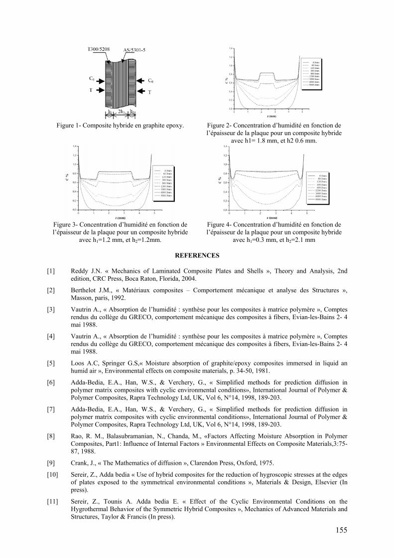
155
Figure 1- Composite hybride en graphite epoxy. Figure 2- Concentration d’humidité en fonction de
l’épaisseur de la plaque pour un composite hybride avec h1= 1.8 mm, et h2 0.6 mm.
Figure 3- Concentration d’humidité en fonction de l’épaisseur de la plaque pour un composite hybride
avec h1=1.2 mm, et h2=1.2mm.
Figure 4- Concentration d’humidité en fonction de l’épaisseur de la plaque pour un composite hybride
avec h1=0.3 mm, et h2=2.1 mm
REFERENCES
[1] Reddy J.N. « Mechanics of Laminated Composite Plates and Shells », Theory and Analysis, 2nd edition, CRC Press, Boca Raton, Florida, 2004.
[2] Berthelot J.M., « Matériaux composites – Comportement mécanique et analyse des Structures », Masson, paris, 1992.
[3] Vautrin A., « Absorption de l’humidité : synthèse pour les composites à matrice polymère », Comptes rendus du collège du GRECO, comportement mécanique des composites à fibers, Evian-les-Bains 2- 4 mai 1988.
[4] Vautrin A., « Absorption de l’humidité : synthèse pour les composites à matrice polymère », Comptes rendus du collège du GRECO, comportement mécanique des composites à fibers, Evian-les-Bains 2- 4 mai 1988.
[5] Loos A.C, Springer G.S,« Moisture absorption of graphite/epoxy composites immersed in liquid an humid air », Environmental effects on composite materials, p. 34-50, 1981.
[6] Adda-Bedia, E.A., Han, W.S., & Verchery, G., « Simplified methods for prediction diffusion in polymer matrix composites with cyclic environmental conditions», International Journal of Polymer & Polymer Composites, Rapra Technology Ltd, UK, Vol 6, N°14, 1998, 189-203.
[7] Adda-Bedia, E.A., Han, W.S., & Verchery, G., « Simplified methods for prediction diffusion in polymer matrix composites with cyclic environmental conditions», International Journal of Polymer & Polymer Composites, Rapra Technology Ltd, UK, Vol 6, N°14, 1998, 189-203.
[8] Rao, R. M., Balasubramanian, N., Chanda, M., «Factors Affecting Moisture Absorption in Polymer Composites, Part1: Influence of Internal Factors » Environmental Effects on Composite Materials,3:75-87, 1988.
[9] Crank, J., « The Mathematics of diffusion », Clarendon Press, Oxford, 1975.
[10] Sereir, Z., Adda bedia « Use of hybrid composites for the reduction of hygroscopic stresses at the edges of plates exposed to the symmetrical environmental conditions », Materials & Design, Elsevier (In press).
[11] Sereir, Z., Tounis A. Adda bedia E. « Effect of the Cyclic Environmental Conditions on the Hygrothermal Behavior of the Symmetric Hybrid Composites », Mechanics of Advanced Materials and Structures, Taylor & Francis (In press).

156
SHEAR FLOW SIMULATION OF FIBRE-REINFORCED THERMOSET COMPOSITES DURING THE EARLY STAGES OF PROCESSING
Mehdi Haghshenas, Reza Vaziri, Anoush Poursartip Composites Group
Departments of Civil Engineering & Materials Engineering The University of British Columbia
Vancouver, BC Canada
ABSTRACT
In autoclave processing of thermoset composites, two flow phenomena occur before gelation of the curing resin: percolation of the resin through the fibre bed, and shear flow of the resin and fibre-bed together. An extensive amount of work has focused on modeling the percolation flow of resin in autoclave processing of thermoset composites (Hubert et al. [1]). With the introduction of newer generations of thermoset resin and use of highly viscous epoxies in manufacturing of prepregs, shearing behaviour of resin and fibres is of particular importance.
Hubert et al. [2] carried out a series of transverse squeeze flow experiments on samples of uncured unidirectional thermoset composites. He presented profiles of the lateral barrelling deformation measured at various time intervals. The observed response history strongly suggests that this mode of deformation has a viscoelastic nature. Similar experiments on thermoplastic fibre reinforced composites have been modeled in the literature by assuming that the composite behaves as a Newtonian or non-Newtonian fluid [3]. Figure 1 shows a schematic representation of the transverse squeeze flow experiment and the two different flow phenomena observed.
In this work, we present a numerical model based on flow through deforming porous media that aims at capturing both percolation and shear flow mechanisms. To account for a more general momentum balance equation for the fluid phase, the Brinkman term is included in Darcy’s law. A volume averaging method [4] is incorporated to arrive at macro-mechanical governing equations of flow in deforming porous media. The Brinkman equation considers shear stress components as well as pressure in the fluid phase, which leads to a complete representation of stress in the resin. This also allows the treatment of a purely viscous flow problem as a special case of the general two-phase model.
When Darcy’s law is used, it is usually substituted in the mass conservation equation and the resulting differential equation is solved coupled with the solid phase equilibrium equation (e.g. the approach taken in [5-6]). Here, the above substitution is not trivial and we will solve three simultaneous equations; namely, mass conservation, resin equilibrium, and the total equilibrium equation. Therefore, the current FE model has three major independent variables: the total displacement field, the resin relative velocity field, and the resin pressure.
A specialized element used for modelling viscous incompressible flow is modified to accommodate for the extra variables. Special treatments are considered to account for the gradient of resin volume fraction, which is present in the element formulation. These considerations include evaluation of the second derivatives of the shape functions, and computation of the value of the gradient of resin volume fraction at integration points using those derivatives.
To account for the viscoelastic nature of the response history of the transverse squeeze flow experiments, different viscoelastic models are introduced in the constitutive equation of the two phase medium.

157
Figure 1- Schematic representation of the transverse squeeze flow experiment and the two flow mechanisms.
REFERENCES
[1] Hubert, P., Poursartip, A., "A review of flow and compaction modelling relevant to thermoset matrix laminate processing", Journal of Reinforced Plastics and Composites, Vol. 17, No. 4, pp. 286-318, 1998.
[2] Hubert, P., Poursartip, A., Bradley, W. L., "Direct observations in fibre reinforced composite materials during processing", Proceedings of the American Society for Composites 11th Technical Conference, Atlanta, Georgia, pp. 738-747, 1996.
[3] Shuler, S. F., Advani, S. G., "Transverse squeeze flow of concentrated aligned fibers in viscous fluids", Journal of Non-Newtonian Fluid Mechancis, Vol. 65, No. 1, pp. 47-74, 1996.
[4] Tucker III, C. L., Dessenberger, R. B., "Optimal curing for flow and heat transfer in stationary fiber beds", In: Advani, S. G. Editor, Flow and rheology in polymer composite manufacturing, Amsterdam, Elsevier, 1994, Chapter 8, pp. 257-323.
[5] Hubert, P., Vaziri, R., Poursartip, A., "A two-dimensional flow model for the process simulation of complex shape composite laminates", International Journal for Numerical Methods in Engineering, Vol. 44, No. 1, pp. 1-26, 1999.
[6] Li, M., Tucker III, C. L., "Modeling and simulation of two-dimensional consolidation for thermoset matrix composites", Composites: Part A, Vol. 33, No. 6, pp. 877-892, 2002.

158
MEASUREMENTS OF THE SNAP-THROUGH BEHAVIOUR AND SNAP-THROUGH FATIGUE PERFORMANCE OF BISTABLE UNSYMMETRIC COMPOSITE STRUCTURES
Kevin Potter Department of Aerospace Engineering,
University of Bristol, UK
ABSTRACT
Above some critical length to thickness ratio, square unsymmetrical 0.90 carbon fibre/epoxy laminates exhibit two stable geometrical states as shown in Figure 1. Such laminates have been widely studied [1, 2, 3] and can be used as simple models to explore the sorts of responses that may be required in the development of morphing
structures. Recently, more complex lay-ups potentially giving many stable states, rather than just two, have been reported [4], but the work discussed here is generally limited to the simpler structures.
Some papers have discussed the snap-through behaviour of the square unsymmetrical 0.90 carbon fibre/epoxy laminates in terms of the loads required to make the laminate snap between states [5], but in general the two states seem to have been treated as if there are no intermediate steps between the two extremes. This paper presents some data on the load/deflection behaviour of the square
unsymmetrical 0.90 carbon fibre/epoxy laminates when measured using point loading under displacement control so that the shapes may be studied in more detail during the deformation. The use of displacement rather than load control reveals some unexpected features of the snap-through phenomenon. The load / deflection curve is of the form shown in Figure 2 and shows a clearly defined step in the region where the load is falling rapidly as deflection increases towards the snap-through point. Even though there is a steep effective negative stiffness at this point the behaviour is entirely stable and the sample can be wound both ways through the step region without triggering the gross snap-through or similar effects.
Examination of the geometry of the laminate at this point shows that one side of the laminate has in fact experienced the snap-through so that at that point the laminate exhibits some characteristics of both the stable states available to it, see Figure 3. Leaving aside at this stage the question of how such bistable laminates might be actuated between states, if we are to use such structures in morphing arrangements it is also necessary to understand something about the speed of response
and the fatigue performance. This has been measured for samples identical to those used for the quasi-static measurements at 150mm x 150mm. In this case the samples were supported between pairs of rods at two diagonally opposite corners to minimize constraint; and actuated by a displacement applied, as before, at the centre of the plate. The displacements were applied by two solenoids, set to operate on a sinusoidal waveform 1800 out of phase with each other so that one solenoid just pushes the plate past the snap-through point and the other pushes it back.
Figure 1- The two stable cylindrical states of an unsymmetric 0.90 laminate.
Figure 2- Load/displacement for snap through.
Figure 3- Geometry of intermediate state.
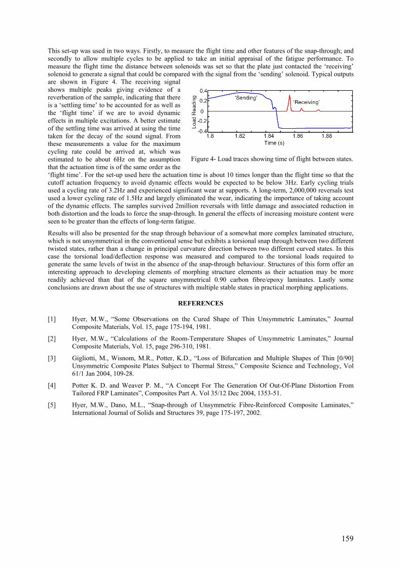
159
This set-up was used in two ways. Firstly, to measure the flight time and other features of the snap-through; and secondly to allow multiple cycles to be applied to take an initial appraisal of the fatigue performance. To measure the flight time the distance between solenoids was set so that the plate just contacted the ‘receiving’ solenoid to generate a signal that could be compared with the signal from the ‘sending’ solenoid. Typical outputs are shown in Figure 4. The receiving signal shows multiple peaks giving evidence of a reverberation of the sample, indicating that there is a ‘settling time’ to be accounted for as well as the ‘flight time’ if we are to avoid dynamic effects in multiple excitations. A better estimate of the settling time was arrived at using the time taken for the decay of the sound signal. From these measurements a value for the maximum cycling rate could be arrived at, which was estimated to be about 6Hz on the assumption that the actuation time is of the same order as the ‘flight time’. For the set-up used here the actuation time is about 10 times longer than the flight time so that the cutoff actuation frequency to avoid dynamic effects would be expected to be below 3Hz. Early cycling trials used a cycling rate of 3.2Hz and experienced significant wear at supports. A long-term, 2,000,000 reversals test used a lower cycling rate of 1.5Hz and largely eliminated the wear, indicating the importance of taking account of the dynamic effects. The samples survived 2million reversals with little damage and associated reduction in both distortion and the loads to force the snap-through. In general the effects of increasing moisture content were seen to be greater than the effects of long-term fatigue.
Results will also be presented for the snap through behaviour of a somewhat more complex laminated structure, which is not unsymmetrical in the conventional sense but exhibits a torsional snap through between two different twisted states, rather than a change in principal curvature direction between two different curved states. In this case the torsional load/deflection response was measured and compared to the torsional loads required to generate the same levels of twist in the absence of the snap-through behaviour. Structures of this form offer an interesting approach to developing elements of morphing structure elements as their actuation may be more readily achieved than that of the square unsymmetrical 0.90 carbon fibre/epoxy laminates. Lastly some conclusions are drawn about the use of structures with multiple stable states in practical morphing applications.
REFERENCES
[1] Hyer, M.W., “Some Observations on the Cured Shape of Thin Unsymmetric Laminates,” Journal Composite Materials, Vol. 15, page 175-194, 1981.
[2] Hyer, M.W., “Calculations of the Room-Temperature Shapes of Unsymmetric Laminates,” Journal Composite Materials, Vol. 15, page 296-310, 1981.
[3] Gigliotti, M., Wisnom, M.R., Potter, K.D., “Loss of Bifurcation and Multiple Shapes of Thin [0/90] Unsymmetric Composite Plates Subject to Thermal Stress,” Composite Science and Technology, Vol 61/1 Jan 2004, 109-28.
[4] Potter K. D. and Weaver P. M., “A Concept For The Generation Of Out-Of-Plane Distortion From Tailored FRP Laminates”, Composites Part A. Vol 35/12 Dec 2004, 1353-51.
[5] Hyer, M.W., Dano, M.L., “Snap-through of Unsymmetric Fibre-Reinforced Composite Laminates,” International Journal of Solids and Structures 39, page 175-197, 2002.
Figure 4- Load traces showing time of flight between states.


161
SESSION 10 – NOVEL METHODS AND RESIDUAL STRESSES II
Chair: Prof. John Botsis Swiss Federal Institute of Technology, Switzerland
Wednesday 12th April 11:15 – 12:55
162
MODAL IDENTIFICATION OF THE ELASTIC PROPERTIES IN COMPOSITE SANDWICH STRUCTURES
Marco Matter, Thomas Gmür, Joël Cugnoni and Alain Schorderet School of Engineering (STI)
Ecole polytechnique fédérale de Lausanne (EPFL) Switzerland
ABSTRACT
Sandwich structures with composite face sheets and lightweight core are nowadays intensively used in engineering fields where high stiffness and strength combined with a reduced weight is of prime importance. Typical applications where this construction type is attractive include among others ship hulls, aircraft wings, racing car frames or sporting goods. Despite their attractiveness, sandwich constructions can only be used with confidence in engineering applications if their elastic properties are thoroughly characterized. The high orthotropy and het-erogeneity of these materials, as well as their specific production process, increase however the difficulty to identify their constitutive parameters in comparison to multilayered composites or usual materials such as met-als, so that a powerful and effective parameter identification method is highly desirable.
Modal identification procedures have shown great advantages over static characterization methods. Instead of performing a specific static test per elastic parameter on several specimens of the material to be identified, a dy-namic identification requires only one full-field measure on a sole specimen, which reduces significantly the parameter characterization time. In addition, dynamic identification is a non-destructive technique which allows a measurement without altering the physical properties of the structural components under investigation. In this paper, the development of a modal method for identifying the elastic properties of composite sandwich structures is presented. Based upon a mixed numerical-experimental dynamic identification already validated on multilay-ered composite plates, the proposed method is extended to sandwich constructions and exhibits excellent char-acterization properties.
Dynamic identification techniques rely on the minimisation of the discrepancies between the natural frequencies and mode shapes of structures modelled with a highly accurate composite finite element formulation with adjust-able elastic properties and the corresponding experimental quantities. By choosing appropriate error functionals which take into account not only the discrepancies between the predicted and measured natural frequencies but also the differences in amplitude, position or orthogonality between the simulated and measured mode shapes, the convergence of the estimated elastic parameters to the true values can be improved.
On the computational level, different finite element models have been investigated in order to define the most suitable numerical formulation for modelling sandwich structures. Since the sandwich plates considered were made of face sheets in a rigid orthotropic material such as carbon/epoxy embedding a softer core with a low den-sity like foam or honeycomb, the difficulty in modelling such type of material lies in the proper representation of the discontinuity of the through-the-thickness displacement derivative at the interfaces of the sandwich compo-nents. As the displacement in the thickness direction shows a well pronounced zigzag variation due to the strong difference of the elastic properties between the face sheets and the core of sandwich constructions, the true dis-placement field can not be well estimated when using a multilayered shell finite element formulation based upon the first- or higher-order shear deformation theory. A p-order shell finite element model including also piecewise linear functions for the through-the-thickness displacement has been formulated. This model has been compared to several other numerical models such as the 3D solid orthotropic formulation in order to find the most powerful model in terms of accuracy and computation time in the identification process.
On the experimental level, a measurement setup, formed by a scanning laser vibrometer Polytec PSV200, a con-trolled pseudo-random and periodic chirp signal generator and an electro-dynamic shaker to generate the excita-tion of the specimens, has been mounted in an anechoic chamber (Figure 1). The correlation between the experi-mental tests and the numerical simulations is improved by choosing free boundary conditions for the structures tested, which ensures a good repeatability of the measures. Three sandwich composite plates have been selected, all of them being made of 0°/90° carbon/epoxy face sheets and a honeycomb (Nomex) core or two foam core of different thicknesses. They have been subjected to an excitation in the frequency range from 200 Hz to 15 kHz in order to find the lowest 15 natural frequencies and the corresponding mode shapes. Measured with a dynamic load cell, the input load ranged from 0 to 45 N. Captured with the laser interferometer, the response of the specimens to the excitation has been treated with a multi-degree-of-freedom curve fitting software to extract the modal data of interest (Figure 2).

163
Figure 1- Experimental setup
On the optimisation level, adequate modal identification criteria have been defined for quantifying the residuals on the constitutive parameters during the identification iterations. Sensitive to all the material properties to be identified, original error norms which take into account all the modal data available have been developed. Based upon the natural frequencies, the mode shape components, the location of the nodal lines, and the diagonal and off-diagonal mode shape correlation coefficients associated to the classical modal assurance criterion (MAC), these error norms are weighted and combined in a global objective function which is minimized by using a clas-sical Levenberg-Marquardt nonlinear least square optimisation algorithm. Required as in any minimization proc-ess, the derivatives of the objective function with respect to the elastic parameters to be identified are computed numerically with a finite difference scheme.
In a first step, different numerical models are compared and discussed using a theoretical test case of a sandwich plate with given elastic properties. From these investigations, it is concluded that, among the equivalent single layer models, only the finite element formulation based upon the p-order shear deformation theory and including a zigzag form for the through-the-thickness displacement approximation is sufficiently accurate for modelling sandwich structures. In a second time, several real identification examples with sandwich plates made of 0°/90° carbon/epoxy face sheets and a honeycomb or foam core are presented. It is also shown that the uniqueness of the parameter estimation is not necessarily guaranteed in sandwich constructions as two different sets of elastic properties can yield to the same dynamic behaviour. Overall, the proposed identification method can accurately determine the in-plane Young’s moduli of the face sheets and the transverse and in-plane shear moduli of the core.
This work was partially supported by the Swiss National Science Foundation (FNS), grant No. 200020-105524.
Figure 2- First mode shapes of the sandwich plate
164
EXPERIMENTAL AND NUMERICAL ANALYSES OF NON-SYMMETRIC COMPOSITE LAMINATES CURVATURES
Antonio Claret Palerosi Control and Space Mechanics Division
INPE - Instituto Nacional de Pesquisas Espaciais Brazil
Sergio Frascino Muller de Almeida
Department of Mechanical Engineering ITA - Instituto Tecnologico de Aeronautica
Brazil
ABSTRACT
Due to the mismatch in the thermal properties of the constituents, manufacturing thermal residual stresses are always present in laminated polymeric composites and may affect both the strength and the elastic behavior of the structure. Therefore, the distribution of the residual stresses may be quite significant in design and should be accurately predicted. The study of the variation of the curvature of non-symmetric laminates with temperature provides a measure of the residual stresses and the mechanical behavior of the material with temperature.
In previous works [1, 2], the development of a simple digital camera imaging technique to measure the flexural and torsional curvatures of composite non-symmetric laminates above the room temperature was reported. The method was proved to be reliable, accurate, easy to implement and presents advantages when compared with other alternatives, like strain-gages or the shadow Moiré. The proposed technique was applied to measure the curvature of cross-ply and angle-ply strips taken from carbon-epoxy non-symmetric laminate plates. The results of geometrically non-linear finite element models (FEM) were correlated to curvature-temperature experimental measurements in the range of 20 to 80oC. An approximately constant shift in temperature was observed for all [0n/90m] class of laminates investigated. It was shown that the FEM yields excellent approximation to the measured curvatures provided that the reference temperature in the FEM is properly shifted. The temperature shift was assumed to represent the unmodeled factors in the simulation model: the material viscoelasticity and the variations on the material physical properties with temperature; additionally, a portion of the shift was credited to the autoclave process. These factors are difficult and uncertain to evaluate. Note that the viscoelastic effects were accounted for during experiments by observing a proper dwelling time between measurements. For each different laminate a different shift in the reference temperature was found indicating that the required change in the reference temperature may depend on the laminate lay-up and thickness. The concept of using an “equivalent cure temperature”, determined by curvature-temperature experiments and simulations, instead of the stress-free temperature to determine the thermal residual stresses was than proposed.
The present work discusses the simulation methods used in the current investigation for determination of the non-symmetric laminate strips curvatures. The Classical Laminate Theory (CLT) is the base of most calculations used to predict the response of composite laminates to static, dynamic and thermal loads. The CLT is a linear theory and predicts that non-symmetrical cross-ply laminates of any size should always develop saddle curvatures. However, this approach is unable to correctly predict the shape of thin laminates since large out-ofplane displacements restrict the development of curvatures and the laminate can present a cylindrical shape depending on the aspect ratio of the sample [3]. An analytical approach known as the “extended CLT” [3] including non-linear terms in the strain-displacement relationship in the sense of von Karman has been proposed to deal with the geometrically non-linear nature of the problem. The “extended CLT” models are based on the minimization of the total potential energy and on the Rayleigh-Ritz approximations of the displacement fields. An alternative approach is used in [4] where one of the curvatures within the CLT analysis is set to zero since after a certain aspect ratio of the sample the deformation is shown to be cylindrical instead of the saddle shape.
Initially a semi-analytical model was built to predict the curvatures of rectangular laminate plates. The model used non-linear approximation polynomials of third order and fourteen coefficients as described in [3]. It was observed that for those laminates and temperatures where the geometrical non-linearity manifest in a more severe degree the approximated polynomials assumed are no longer valid and the model could not accurately predict the experimental results. However, the analytical model indicated that the aspect ratio of the laminates should be taken into account. Figure 1 shows the change in sample curvature by varying the width while keeping the length constant. From the three possible solutions after point B, two do not represent a stable solution, the branches BD and BE. The predicted curvature is described by branch ABC that presents a high sensitivity to changes in the sample width near point B. This indicates that a judicious choice of the sample aspect ratio must be made to avoid large changes in the curvature due to small changes in the sample width. Moreover, it unveils that the sample (a narrow and long strip) behaves like a plate rather than a beam.

165
Figure 1- Flexural curvature against sample width (sample length equal to 280 mm).
Geometrically non-linear finite element models, which do not account either for viscoelastic effects or for the variation of material properties with temperature, were then developed for comparison with the experimental results [1, 2]. Preliminary analysis results showed that the gravitational effects should be considered in the models, particularly for the thin laminates. Figure 2 shows a comparison among the different simulation methods for two different laminates, [03/903] and [0/90]. The experiments and simulation data are from temperature steps of 15 ºC; the figure shows the data fitted by a quadratic polynomial. As can be seen in the figure, the FEM results present the best approximation displayed by an approximately constant shift to the experimental data. The CLT could be used for the [03/903] laminate but is quite inaccurate for the [0/90] that has a more pronounced non-linear behavior. The extended CLT deviates from the experimental data as the temperature increases, particularly for the [0/90]. In the CLT analysis setting one of the curvatures to zero, the results for the [03/903] laminate are close to the extended CLT results whereas it presents large discrepancy for the [0/90] laminate.
Figure 2- Experimental data and simulation results for two different cross-ply laminates.
ACKNOWLEDGEMENTS
The authors wish to thank Embraer for supplying the materials and manufacturing all of the samples used in this work and Hexcel for the prompt support. The second author acknowledges the financial support received from CNPq under grant 302112/2003-0.
REFERENCES
[1] Palerosi, A. C., Almeida, S. F. M., "Curvature Measurements of Non-Symmetric Laminates Using Image Processing", 15th International Congress of Composite Materials Proceedings, Durban, South Africa, 2005.
[2] Palerosi, A. C., Almeida, S. F. M., "Non-symmetric Angle-ply Laminates Curvature Measurements Using Digital Imaging Processing”, International Conference on Science and Technology of Composite Materials, Buenos Aires, Argentina, 2005.
[3] Dano, M.-L., Hyer, M. W. Thermally-induced deformation behavior of unsymmetric laminates. International Journal of Solids and Structures, Vol. 35, No. 17, pp. 2101-2120, 1998.
[4] Radford, D. W., “Cure Shrinkage Induced Warpage In Flat Uni-axial Composites”, Journal of Composite Technology & Research, Vol. 15, No. 4, pp. 290-296, 1993.

166
POINT TO POINT NON-CONTACT VIDEO EXTENSOMETRY FOR COMPOSITE MATERIALS AND STRUCTURES – A COMPARISON WITH FULL-FIELD METHODS
Kevin Potter & Chris Setchell Imetrum Ltd. Bristol. UK
www.imetrum.com
ABSTRACT
A variety of full-field displacement and strain measurement methods [1] have been applied to the testing of composite materials and structures. These include methods based on the use of video cameras via normalised correlation approaches; the use of grid methods based on moiré fringe methods; the use of laser speckle interferometry methods and the use of photoelasticity. The great advantage that all these techniques have is that the output is in terms of the distribution of displacement and, with additional processing, strain across the surface of the sample. This allows the direct visualisation of strain fields, for example for comparison with FEA outputs and may be useful in visualising changes in surface strain caused by sub-surface events. The application of these methods has been very valuable in demonstrating how non-uniform the stress fields may be in conventional materials test specimens, especially with composite materials. Having said that, the evidence that such methods provide an adequately accurate and reliable method of determining materials properties is somewhat mixed, with rather variable results being obtained when measuring the moduli of standard engineering materials. For the majority of these methods the measurements that are made are arrived by off-line computations, and in some cases such as ESPI the individual snapshots that are used to capture a changing load and strain environment are taken with the specimens in a fixed position, potentially allowing creep and strain redistribution to occur.
The work on the Video Gauge that is reported here uses similar algorithms to those used in normalised correlation approaches to track and measure the position of targets in a video field, and then applies additional and novel algorithms to further refine the estimate of position. However, rather than effectively mapping the sample with an array of targets that covers the whole surface (which usually requires a speckle pattern to be applied) a set of specific targets are identified on or added to the surface and the displacements of and strains between these targets are tracked and measured. This has several advantages. One major advantage is that with a reduced computational load the displacements and/or strains can be tracked in real time and hence used directly to provide feedback control to the test machine.
It is also very straightforward to compare the outputs of the Video gauge to conventional strain measurement methods such as strain gauges or extensometers as shown in Figure 1. In this test the outputs of the three gauging methods showed a similar level of scatter and all recorded the expected value of modulus. In another validation test two targets were applied to the rigid cross-head of a test
machine and traversed across the field of view whilst the distance between the targets was recorded using the Video Gauge. In this case the variability in the apparent distance between the targets can be taken as a measure of the resolution with which strain can be measured. Figure 2 shows the data for the difference between expected and actual measurements in terms of pixels. The red line is the RMS value of the variability, which can be taken as a measure of resolution. As can be seen in Figure 2 the RMS variation in the distance is about 1/200th of a pixel. To compare this to a strain resolution we need to look at the initial target to target distance. On a conservative basis, taking 1/100th of a pixel rather than 1/200th and assuming the use of a megapixel camera, if the targets are initially 500 pixels apart the strain resolution
becomes 20με or 0.002%. This is the sort of target to target distance in pixels that would be appropriate for measuring strain in conventional tests, e.g. for moduli determinations allowing for the rigid body movements of the sample. If a more localised strain determination were required an initial target to target distance of say 50 pixels would necessarily reduce the reliability of the computed strains. For this reason, in addition to the use of novel and improved algorithms the Video Gauge will give a demonstrably better performance than full-field normalised correlation methods, as these must use local comparisons of target region separations.
Figure 1- Sample set up for Video Gauge, strain Gauge (on back face) and extensometer.
Figure 2- Measured variation in pixel distance between 2 fixed targets.

167
Figure 3 shows tensile stress vs strain and Poisson’s ratio data measured at a gauge length of 0.5mm on a 0.5 mm thick fragile and delicate adhesive specimen [2]. This represents the smallest sample size that has been measured to date with the Video Gauge, although there is no reason in principle that images acquired through microscopes could not be processed in exactly the same way, using for example individual fibres in a composite as targets. Although the proper measurement of the resolution must be defined in pixels it is interesting to convert the resolution into absolute measurements for various sample sizes (based on the same conservative assumptions as used before). For a standard 10mm wide specimen the resolution would be 200nm, dropping to 10nm for a gauge length of 0.5mm and a 1nm resolution is easily achievable through low power microscope images. The Video Gauge can then be used as a precision non-contact measurement device when calibrated against some standard known target to target distance. It has been used in this way for example to
monitor the deck displacements on a long span bridge and to monitor the compaction and shrinkage processes in the cure of a composite laminate. Figure 4 shows the output from that compaction test. The resolution of the displacement output was sensitive enough to allow values for the expansion coefficients and chemical shrinkage to be extracted as well as the gross compaction behaviour.
Whilst the technique does not have the immediacy of the full-field approaches in terms of the ability to compare directly between FEA and strain maps it has advantages in terms of resolution, the relative simplicity of set-up, use and comparison to calibration standards, as
well as offering a scale insensitive displacement and strain measurement capability usable from microscopic to civil engineering scales in real time on hard to measure samples such as composites or biological materials.
REFERENCES
[1] Gary Cloud. Optical methods of engineering analysis. Cambridge University Press. 1995.
[2] Towse A, Setchell C, Potter K, Clarke A, Macdonald J, Wisnom M & Adams R. Use experience with a developmental general purpose non-contacting extensometer with high resolution. ASTM STP 1323, 2001, pp 36-51.
Figure 3- Stress/strain curve for adhesive specimen with 0.5mm gauge length.
Figure 4

168
EVALUATION OF THE MATERIAL PROPERTIES OF RESIN-IMPREGNATED NOMEX® PAPER AS BASIS FOR THE SIMULATION OF THE IMPACT BEHAVIOUR OF HONEYCOMB SANDWICH
Falk Hähnel, Klaus Wolf Department of Aerospace Engineering
Technische Universität Dresden Helmholtzstraße 10, 01062 Dresden
Germany
ABSTRACT
Driven by stringent weight saving requirements composite sandwich construction has evolved as one of the basic structural design concepts for load-carrying components of advanced aeroplanes and helicopters. Particularly, sandwich using laminated carbon fibre reinforced plastics (CFRP) as face sheets and NOMEX® honeycombs as core material is increasingly used due to features such as high strength-to-weight and stiffness-to-weight ratios as well as an excellent fatigue behaviour. While offering unique advantages, sandwich is also prone to a range of defects and damages. Due to the thin brittle skins and the weak core material CFRP sandwich structures are particularly susceptible to impact loading which may accidentally occur during assembly or operation of aircraft. Since these damages may have detrimental effects on the load carrying capability, they have to be considered in the damage tolerant design of aircraft structures. For that purpose it is necessary to determine the extent of damage in sandwich structures, resulting from impact events such as tool drop or thrown up debris. Up to now this task is mainly done experimentally by using drop weights to simulate the impact loading and NDT methods to determine the damage size. Since these experimental procedures are rather costly and time consuming, there is a clear need to supplement them by reliable numerical simulation tools. Usually, explicit finite element methods are employed for this task.
As far as the global behaviour of sandwich components is investigated by finite element methods it is sufficient to model the structure by using shell elements for the skins and solid elements for the core. In the case of honeycombs such models permit only a macro-mechanical description of the core behaviour. Thus, it is not possible to account for local failure modes of the hexagonal cell structure. Nevertheless, these local effects are important, if impact loading is investigated. For this kind of problem a detailed modelling of the honeycomb cell structure is required [1, 2].
Impact loading of honeycomb sandwich results in very complex damage modes in the core as can be seen in Figure 1a. For example, in the centre of the impact area the honeycomb material is crushed. This damage is mainly the result of local buckling of the cell walls and compressive failure of the resin-impregnated NOMEX paper. Closer to the edge of the impact area the core is subjected to high shear forces which results in shear cracks in the cell walls. This clearly shows that material properties such as stiffness and strength of the honeycomb material are crucial parameters for the formation of damage in the sandwich. Therefore, the knowledge of these properties are essential for a reliable numerical simulation of impact loaded honeycomb sandwich structures as shown in Figure 1b.
Usually, honeycomb manufacturers provide material data only for honeycomb blocks instead of the impregnated papers used as core material. So, one approach is to determine the paper properties from the global core properties. This can be done by numerical simulation of the tests used to measure the global properties [1]. This approach provides only averaged data and it is difficult to identify the non-linear behaviour of the material. Therefore, a research project was initiated which aimed at the determination of material properties of resinimpregnated NOMEX paper.
Two main problems had to be solved. The first one was to get sheets of impregnated paper with a sufficient size for testing. Since the hexagons of the honeycombs usually applied in aircraft structures are very small, it is not possible to cut test specimens directly from the cell walls. Therefore, larger sheets of NOMEX papers had to be produced by a honeycomb manufacturer. The applied process was similar to that used for the production of standard honeycomb cores.
The second problem was to find appropriate experimental methods. In a first move, standard test methods were evaluated [e.g. 3, 4, 5] which are normally used to determine material properties of paper and board. The result of this evaluation was that only the standard test for tensile properties [3] is applicable. Therefore, two new tests have been developed. The first one is used to measure the mechanical behaviour of impregnated NOMEX under compression (see Figure 2, left). It is based on the ring crush method of ISO 12192 which was modified to prevent premature buckling of the test specimen and to provide well defined clamping conditions. The second test fixture was designed for the determination of the behaviour of NOMEX paper under shear loading (see Figure 2, right). For this test fixture the concept of rail-shear tests was chosen and adapted to the special requirements of the thin-walled material.
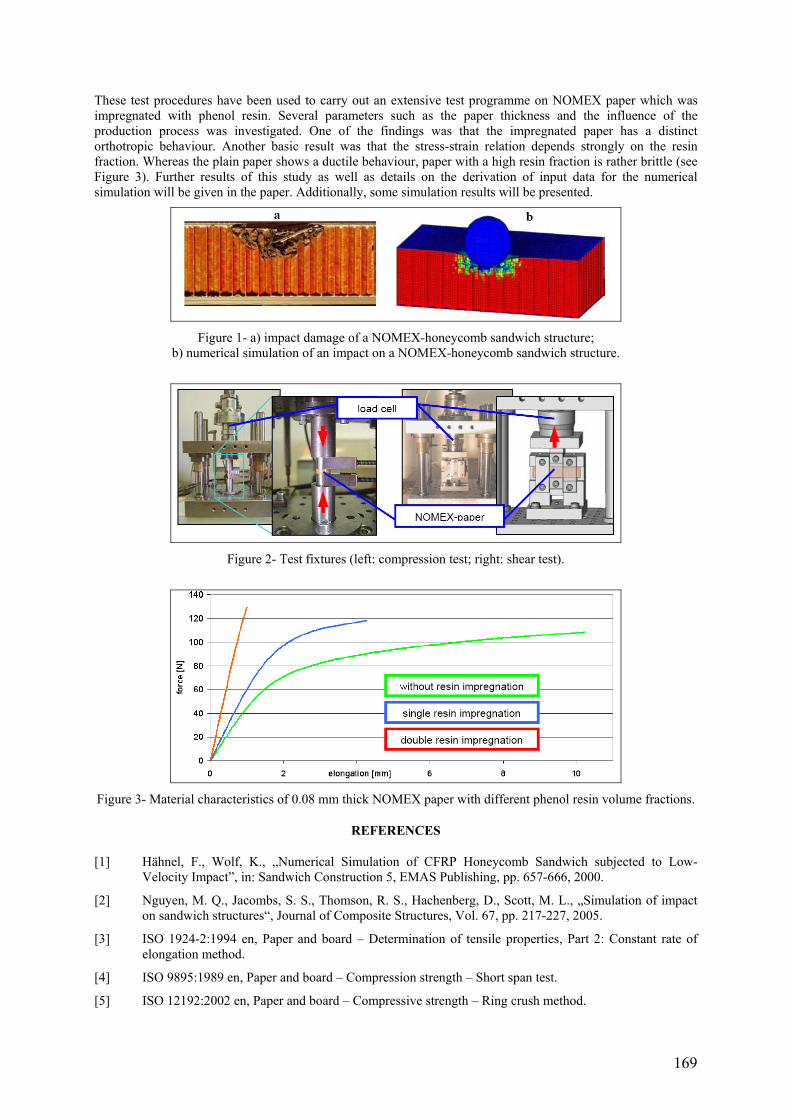
169
These test procedures have been used to carry out an extensive test programme on NOMEX paper which was impregnated with phenol resin. Several parameters such as the paper thickness and the influence of the production process was investigated. One of the findings was that the impregnated paper has a distinct orthotropic behaviour. Another basic result was that the stress-strain relation depends strongly on the resin fraction. Whereas the plain paper shows a ductile behaviour, paper with a high resin fraction is rather brittle (see Figure 3). Further results of this study as well as details on the derivation of input data for the numerical simulation will be given in the paper. Additionally, some simulation results will be presented.
Figure 1- a) impact damage of a NOMEX-honeycomb sandwich structure;
b) numerical simulation of an impact on a NOMEX-honeycomb sandwich structure.
Figure 2- Test fixtures (left: compression test; right: shear test).
Figure 3- Material characteristics of 0.08 mm thick NOMEX paper with different phenol resin volume fractions.
REFERENCES
[1] Hähnel, F., Wolf, K., „Numerical Simulation of CFRP Honeycomb Sandwich subjected to Low-Velocity Impact”, in: Sandwich Construction 5, EMAS Publishing, pp. 657-666, 2000.
[2] Nguyen, M. Q., Jacombs, S. S., Thomson, R. S., Hachenberg, D., Scott, M. L., „Simulation of impact on sandwich structures“, Journal of Composite Structures, Vol. 67, pp. 217-227, 2005.
[3] ISO 1924-2:1994 en, Paper and board – Determination of tensile properties, Part 2: Constant rate of elongation method.
[4] ISO 9895:1989 en, Paper and board – Compression strength – Short span test.
[5] ISO 12192:2002 en, Paper and board – Compressive strength – Ring crush method.

171
SESSION 11 – FRACTURE II
Chair: Prof. Janis Varna Lulea University of Technology, Sweden
Wednesday 12th April 14:00 – 15:40

172
DECOHESION ELEMENTS FOR SHELL ANALYSIS
Carlos G. Dávila Computational Structures and Materials Branch
NASA Langley Research Center Hampton, VA 23681
U.S.A.
Albert Turon AMADE, Escola Politècnica Superior
Universitat de Girona, Campus Montilivi, 17071 Girona Spain
Pedro P. Camanho
DEMEGI - Faculdade de Engenharia Universidade do Porto
Portugal
ABSTRACT
Delamination is one of the predominant forms of failure in laminated composites due to the lack of reinforcement in the thickness direction. In order to design structures that are flaw and damage-tolerant, analyses must be conducted to study the propagation of delaminations. The calculation of delaminations can be performed using decohesion elements1. These elements combine aspects of strength-based analysis to predict the onset of damage at the interface, and fracture mechanics to predict the propagation of a delamination.
Decohesion elements are normally designed to represent the separation at the zero-thickness interface between layers of three-dimensional elements (3D). Unfortunately, the softening laws that govern the debonding of the plies often result in extremely slow convergence rates for the solution procedure. In addition, it is often difficult to model zero-thickness interfaces using conventional finite element pre-processors.
Shell elements are more efficient for modeling thin-walled structures than 3D elements. Shell models typically have fewer degrees of freedom than equivalent 3D models and, because the nodes of the sublaminates in a stack are not coincidental, the generation of the decohesion element mesh is easier to perform. The objective of this work is to present the construction of an 8-node decohesion element for modeling delamination between shell elements on the basis of a 3D decohesion element.
The stiffness matrix for conventional 3D decohesion elements is constructed using standard isoparametric linear Lagrangian interpolation functions. The relative displacement jumps between the top and the bottom faces of the element in a local coordinate frame x-y-z are
3Dz
x
y top bot
w wu uv v
δ
δ
δ
⎧ ⎫⎪ ⎪ ⎧ ⎫ ⎧ ⎫⎪ ⎪ ⎪ ⎪⎪ ⎪ ⎪ ⎪ ⎪ ⎪⎪ ⎪ ⎪ ⎪ ⎪ ⎪⎪ ⎪⎪ ⎪ ⎪ ⎪ ⎪ ⎪= − =⎨ ⎬ ⎨ ⎬ ⎨ ⎬⎪ ⎪ ⎪ ⎪ ⎪ ⎪⎪ ⎪ ⎪ ⎪ ⎪ ⎪⎪ ⎪ ⎪ ⎪ ⎪ ⎪⎪ ⎪ ⎪ ⎪ ⎪ ⎪⎩ ⎭ ⎩ ⎭⎪ ⎪⎩ ⎭
BU (1)
where B is the matrix relating the element’s degrees of freedom U to the relative displacements between the top and bottom interfaces. The minimization of the potential energy subjected to the constitutive softening law for decohesion leads to the usual integral over the area of the element, which gives the following element stiffness:
( )( )3T
DA
dA= ∫K B I - D C B (2)
where D is a diagonal matrix representing the damage accumulated at the interface, I is the identity matrix, and C is the undamaged constitutive matrix. Because the stiffness K3D is constructed from the displacements U3D, only three degrees of freedom can be active at a node, i.e., u, v, and w. In the case of shell analysis, the nodes of an element must also account for the three nodal rotations θx, θy, and θz.
The stiffness matrix Kshell of a decohesion element for shell analysis can be constructed by applying the kine-matics of shell deformation to determine the 3D displacement field2. For instance, in the coordinate frame of a shell node, shell and 3D degrees of freedom at an interface can be related as:

173
3
3
1 0 0 0 02
0 1 0 0 0 or 2
0 0 1 0 0 0
jj
j
k jj D shell
k k kj jxjk D yj
zj Shell
xt y
u wtvw
θ
θ
θ
⎧ ⎫⎪ ⎪⎪ ⎪⎡ ⎤ ⎪ ⎪⎪ ⎪⎢ ⎥ ⎪ ⎪⎪ ⎪⎢ ⎥⎧ ⎫⎪ ⎪ ⎪ ⎪⎪ ⎪ ⎢ ⎥ ⎪ ⎪⎪ ⎪ ⎪ ⎪⎢ ⎥⎪ ⎪ ⎪ ⎪= − =⎨ ⎬ ⎨ ⎬⎢ ⎥⎪ ⎪ ⎪ ⎪⎢ ⎥⎪ ⎪ ⎪ ⎪⎪ ⎪ ⎪ ⎪⎢ ⎥⎪ ⎪ ⎪ ⎪⎩ ⎭ ⎪ ⎪⎢ ⎥ ⎪ ⎪⎢ ⎥ ⎪ ⎪⎣ ⎦ ⎪ ⎪⎪ ⎪⎪ ⎪⎩ ⎭
U R U (3)
where tj is the thickness of the shell at node j. For arbitrary orientations of a shell in space, the rectangular matrix R is transformed such that the z-direction is aligned with the normal to the shell. By substituting Equation 3 into the virtual work statement for the decohesion element, it can be shown that the stiffness and internal force of a shell decohesion element can be constructed from any standard decohesion element formulation using the following expressions:
3 Shell 3 and T TShell D D= =K R K R F R F (4)
Layered shell models for progressive delamination can be easily constructed with shell decohesion elements. The model shown in Figure 1 represents a Mixed-Mode Bending specimen, which is used to measure delamination toughness. As the results in Figure 2 show, the results of two- and four-layer shell models correlate well with the results of the 3D analysis of the same specimen.
Figure 1- Two- and 4-layer models of MMB specimen. Figure 2- Analysis results.
The modeling simplicity and computational efficiency of shell element analysis also eases the construction of more complex models, such as the structural component shown in Figure 3 [from Ref. 3.].
This technical presentation will provide additional details on the formulation of decohesion elements for shell analysis as well as several example problems.
Figure 3- Layered shell model of composite lug with decohesion elements.3
REFERENCES
[1] Camanho, P.P., Dávila, C.G., and de Moura, M.F.S.F., "Numerical Simulation of Mixed-Mode Progressive Delamination in Composite Materials," J Comp Mat, Vol. 37, 2003, pp. 1415-1438.
[2] Dávila, C.G., "Solid-to-Shell Transition Elements for the Computation of Interlaminar Stresses," Computing Systems in Engineering, Vol. 5, 1994, pp. 193-202.
[3] Raju, I.S., Dávila, C.G., Glaessgen, E.H., Krishnamurthy, T., and Mason, B.H., "NASA Structural Analysis Rpt on AA587 Accident - Analysis of the RR Lug," 46th SDM Conf., Austin, TX, 2005.

174
DELAMINATION PROPAGATION MEASUREMENT IN AS4/PPS USING LONG GAUGE-LENGTH FBG SENSORS
L. Sorensen, T. Gmür, J. Botsis Laboratoire de mécanique appliquée et d’analyse de fiabilité (LMAF)
Ecole Polytechnique Fédérale de Lausanne (EPFL) Switzerland
ABSTRACT
With the increasing use of polymer composite laminates as structural materials, we need to expand our understanding and characterization of their damage mechanisms. In particular, it is important to consider how a delamination in a laminated composite changes the surrounding internal strain state. In this work, knowledge of the distributed strains near a delamination front is obtained through the use of fibre Bragg grating (FBG) sensors, which are interrogated using an OLCR-based technique that measures the phase of the light reflected at incremental positions in the FBG [1]. This method allows us to precisely locate the delamination crack tip position with respect to an FBG, even under conditions where there is an initial residual strain state that has induced birefringence in the sensor. Since this technique allows the determination of the position, length and growth direction of a delamination crack propagating parallel to the FBG, it represents an advance beyond purely spectral measurements, which may be difficult to interpret and do not uniquely represent a given strain state.
Figure 1- Double cantilever beam specimen, with optical sensor embedded 0.26mm from the crack plane.
To introduce the advantage of this method, consider in a qualitative manner, how an FBG sensor responds to the strains produced by a mode I delamination crack propagation in a double cantilever beam specimen (Figure 1). If the period and index of refraction are changed by applying strains to the FBG, then the wavelength of the reflected light will shift according to the equations developed by Sirkis [2], assuming isothermal loading:
( )[ ]20
11 122bx
z x z yB
n p pλ ε ε ε ελΔ = − + + (0a)
( )[ ]20
11 122by
z y z xB
n p pλ
ε ε ε ελΔ
= − + + (0b)
where Δλbx and Δλby are the shifts in Bragg wavelength for the two polarization axes in the fibre, εi (i = x, y, z) are the principal strain components in the fibre core, and p11 and p12 are the strain-optic Pockel’s constants.
Figure 2- a) Example of a longitudinal strain (εz) distribution in an FBG embedded at a distance of 0.26mm
parallel to the delamination plane b) Spectral distribution measured for a similar case.
Consider an FBG sensor embedded parallel to a bridged delamination crack, and thus subject to a distributed strain field εi(z) along the sensor length (Figure 2a). The wavelengths reflected by the FBG, λbx(z) and λby(z), also become a function of position (z). As a first approximation, the expected spectral response of the FBG can be

175
obtained by neglecting the influence of the transverse strains (for the simplicity of the illustration), so that equations 2a and b both become
( )
( ) ( )1be z
B
zp z
λ ελ
Δ = − (1)
where pe is an effective photoelastic constant. The resulting spectrum should have a large peak at a high wavelength, corresponding to the relatively constant strain in the fibre behind the crack tip. It should also have a large peak at a low wavelength corresponding to the undisturbed portion of the FBG which will reflect the original Bragg wavelength. Finally, there should be a distribution of wavelengths between the two peaks corresponding to the strain evolution around the crack tip. This type of spectrum is illustrated in Figure 2b and was also observed by Takeda et al. [3]. Although this spectral evolution is quite clear, it lacks spatial correlation. A crack could arrive from either end of the FBG and produce the same spectral form, indicating one way in which the spectral form is not a unique indication of strain state. Another complication in the interpretation of wavelength spectra is encountered when a composite contains a residual strain field that creates unequal transverse strains in the embedded FBG, making equation 2 invalid. Under these conditions the spectral response will be dependent on the polarization state of the interrogating light, and therefore, wavelength spectral form, position and amplitude may vary from one measurement to the next, if the polarization state is not maintained.
Figure 3- Measurements of wavelength shifts due to the progression of a delamination crack below an FBG.
In this research we use the OLCR-based approach to measure the FBG response to different delamination lengths (Figure 3). In this way no assumptions need to be made about the distribution or form of the reflected wavelengths and it possible to control the polarization of the light entering the FBG, so that its response is measured separately for each of the polarization axes of the fibre (λbx and λby). We observe that transverse residual strains are unequal in the FBG, causing a birefringence (λbx ≠ λby); however, this difference disappears once the crack front passes below the FBG. Although it is possible to see some effect of the transverse strain field in the FBG response, it is clear that the most significant contribution is made by the longitudinal strains. This is illustrated by comparing the shape of the strain curve in Figure 2a, and the shapes of the measured wavelength curves. In order to provide a complete interpretation of the distributed wavelength measurements, they are coupled with appropriate numerical models to allow for a quantitative description of the strain field around the delamination.
The authors would like to acknowledge the SNSF grant no. 2000-068279 and Cytec Industries Inc.
REFERENCES
[1] Giaccari, P., Limberger, H. G., Salathé, R. P., "Local coupling-coefficient characterization in fiber Bragg gratings", Optics Letters, Vol. 28, pp. 598-600, 2003.
[2] Sirkis, J. S., "Unified approach to phase-strain-temperature models for smart structure interferometric optical fiber sensors: part 1, development", Optical Engineering, Vol. 32, pp. 752-761, 1993.
[3] Takeda, S., Okabe, Y., Takeda, N., “Delamination detection in CFRP laminates with embedded small-diameter fiber Bragg grating sensors”, Composites Part A, Vol. 33, pp. 971-980, 2002.

176
A J INTEGRAL APPROACH FOR THE DETERMINATION OF MIXED MODE COHESIVE LAWS
Bent F. Sørensen Materials Research Department
Risø National Laboratory DK-4000 Roskilde
Denmark
Torben K. Jacobsen LM Glasfiber A/S 6640 Lunderskov
Denmark
ABSTRACT
The mechanical response of failure process zones can be described in terms of cohesive laws, which is the relationship between the local crack opening and the local tractions across the crack faces. Cohesive laws are particular useful to describe failure mechanisms that generate long failure process zones, such as crack bridging in unidirectional fibre composites [1]. Examples are delamination of laminates and interface cracks in sandwich structures. Crack growth in such structures can be modelled by the use of cohesive laws, e.g. by numerical simulation, such as the finite element method. Most simulations have been made with assumed, idealised cohesive laws. Then, cohesive law parameters are calibrated e.g. from pure mode I and mode II tests [2]. However, regarding cohesive laws material properties (i.e. independent of specimen geometry), methods must be developed to measure them. The purpose of the present work is to develop an approach for the determination of mixed mode cohesive laws.
The proposed approach for the determination of mixed mode cohesive laws for large-scale crack bridging problems is based on the application of the J integral [3]. The fracture resistance is determined from mixed mode crack growth experiments conducted at a Double Cantilever Beam specimen loaded with Uneven Bending Moments (DCB-UBM), since for this specimen configuration, the J integral can be determined analytically also in the case of large scale bridging [4]. The specimen configuration is shown schematically in Figure 1.
Figure 1- Schematic drawing of the Double Cantilever Beam specimen loaded with Uneven Bending Moments
(DCB-UBM) test specimen. The end-openings in normal and tangential directions are also indicated.
The normal and shear stresses of the cohesive laws are obtained by from data of the fracture resistance, JR, and the normal and tangential displacements of the cohesive zone. The theory behind the proposed approach will be described.
As an example of measurement, an experimental characterisation of a unidirectional glass-fibre reinforced plastic composite was performed [5]. The cohesive stresses as a function of the normal and tangential end-opening displacements, *
nδ and *tδ , are shown in normalised form in Figures 2 and 3. The results were obtained
by fitting a fourth order Chebyshev polynomials to the measured * *R n tJ δ δ− − data followed by partial
differentiation. The cohesive stresses are set to zero in the steady-state region. Three things are obvious from the results. First, the cohesive stresses start at the peak value and decrease with increasing crack opening. Second, the normal and shear stress depend both on the normal and tangential crack opening displacements. Third, the peak shear stress is more than seven times as high as the peak normal stress.

177
Figure 2- Cohesive normal stress (normalised by the peak normal stress) as a function of normalised normal and
tangential crack opening displacements.
Figure 3- Cohesive shear stress (normalised by the peak normal stress) as a function of normalised normal and
tangential crack opening displacements.
REFERENCES
[1] Suo, Z., Bao, G., Fan, B., "Delamination R-curve phenomena due to damage", J. Mech. Phys. Solids., Vol. 40, pp. 1-16, 1992.
[2] Yang, Q. D., Thouless, M. D., "Mixed-mode fracture analysis of plastically-deforming adhesive joints", Int. J. Fracture, Vol. 110, pp. 175-87, 2001.
[3] Sørensen, B. F., Jacobsen, T. K., "Determination of cohesive laws by the J integral approach", Engineering Fracture Mechanics, Vol. 70, pp. 1841-58, 2003.
[4] Sørensen, B. F., Jørgensen, K., Jacobsen, T. K., Østergaard, R. C., "DCB-specimen loaded with uneven bending moments", International Journal of Fracture, submitted, 2005.
[5] Sørensen, B. F., and Jacobsen, T. K., "Delamination of fibre composites: determination of mixed mode cohesive laws", Journal of the Mechanics and Physics of Solids, manuscript in progress, 2005.

178
SIMULATION OF DELAMINATION UNDER HIGH CYCLE FATIGUE IN COMPOSITE MATERIALS
Albert Turon, Josep Costa AMADE, Escola Politµecnica Superior
Universitat de Girona, Campus Montilivi, 17071 Girona Spain
Pedro P. Camanho
DEMEGI, Faculdade de Engenharia Universidade do Porto
Portugal
Carlos G. Dávila Computational Structures and Materials Branch
NASA Langley Research Center Hampton, VA 23681
U.S.A.
ABSTRACT
Mechanical fatigue, especially high-cycle fatigue, is a common cause of failure of aerospace structures. In laminated composite materials, the fatigue process involves several damage mechanisms that result in the degradation of the material. One of the most important fatigue damage mechanisms is interlaminar damage (delamination), especially in the case of laminated structures devoid of reinforcement in the thickness direction.
There are two basic approaches for the analysis of delamination under fatigue: Fracture Mechanics, which relates the Fatigue Crack Growth Rate as a function of the Energy Release Rate and Mode Ratio; and Damage Mechanics, in which the concept of a Cohesive Zone Model is used to establish damage evolution as a function of the number of cycles. With Damage Mechanics, delamination under cyclic loading is modeled with a constitutive equation that describes the irreversible material separation in terms of crack surface tractions.
In a degradation process involving high cycle-fatigue, damage evolution can be obtained as the sum of the damage caused by static or quasi-static loads and the damage that results from the cyclic loads. The damage evolution produced by cyclic loads is formulated as a function of the number of cycles and strains (or displacement jumps) [1],[2], where a damage evolution law expressed in terms of the number of cycles is established a priori. However, the damage evolution law must be expressed as a function of several parameters that have to be adjusted through a trial-and-error calibration of the whole numerical model. In this paper, an alternative approach is proposed whereby the evolution of damage is based on linking Fracture Mechanics and Damage Mechanics, and relating the evolution of the damage variable, d, with the crack growth rate. The evolution of the damage variable as a function of the number of cycles is related to the evolution of the crack surface:
AN A N∂ ∂ ∂=∂ ∂ ∂d d (1)
where the term NA∂
∂ is the crack growth rate, which must be characterized experimentally. The term
N∂∂d is
obtained from Fracture Mechanics theory and the constitutive damage model.
The present model is implemented by means of a user-written element in ABAQUS by adding the damage evolution law formulated from equation (1) to the decohesion element developed by the authors in previous work [3]. In order to validate the formulation, several analyses were performed using a model with a single decohesion element. The evolution of the interface traction and the maximum (or residual) strength as a function of the number of cycles for a displacement controlled high-cycle fatigue test is shown in Figure 1.

179
Figure 1- Evolution of the interface traction and the maximum interface strength.
The fatigue model is compared with experimental data obtained for a Mode I DCB test. The results obtained by the simulation reproduce correctly the Paris law of crack evolution and correlate well with the experimental results, as shown in Figure 2.
Figure 2- Comparison of the experimental data with the numerical crack growth rate obtained.
REFERENCES
[1] Peerlings, R.H.J., Brekelmans, W.A.M, de Borst, R., and M.G.D. Geers., Gradient-enhaced damage modelling of high-cycle fatigue. International Journal for Numercial Methods in Engineering, 49:1547-1569, 2000.
[2] Robinson, P., Galvanetto, U., Tumino, D., Bellucci, G., and Violeau., D., Numerical simulation of fatigue-driven delaminaton using interface elements. International Journal for Numerical Methods in Engineering, 63:1824-1848, 2005.
[3] Turon, A., Camanho, P.P., Costa, J., Dávila, C.G., An interface damage model for the simulation of delamination under variable-mode ratio in composite materials. NASA/Technical Memorandum 213277, 2004.


181
SESSION 12 – DAMAGE MODELS II
Chair: Dr. Silvestre T. Pinho Imperial College, United Kingdom
Wednesday 12th April 16:00 – 17:15

182
MODELING AND IDENTIFICATION OF ADHESIVE BEHAVIOUR FOR MARINE COMPOSITE APPLICATION: A DEDICATED APPROACH
D. Vernet, C. Cluzel, O. Allix LMT Cachan
61 Avenue du Président Wilson 94235 Cachan Cedex
FRANCE
ABSTRACT
Composite materials are widely used for the design of marine structures [1]. Adhesive bonding is commonly used for these structures but in this context the problem of dimensioning occurs. On the one hand, the behaviour of the polymer material, which is the adhesive, is strongly nonlinear and on the other hand, the techniques of adhesive bonded joint do not allow a total control of the joint thickness in the case of large-sized panels. Our purpose is to develop an interface model [2] to carry out numerical computations of structures at a reasonable cost. But the behaviour of such an element has to be parameterized by data relevant to materials and geometry. Accurate data on the mechanisms of the joint degradation are needed when choosing these parameters and the interface model.
The aim of the performed experiments was to identify the intrinsic behaviour of the adhesive and the influence of the joint dimensions as well as the type of solicitations [3]. Tests on stuck tubes were previously carried out to characterize the material behaviour and were interpreted using a damageable elastoplastic model [4]. Three-dimensional nonlinear simulations then interpret a database of experimental tests on composite structures. The confrontation of experiments and simulations should enable to supplement the material data and to validate the 3D model. The implementation of the 3D non linear model will help to complete the database [5], with simulations on various geometries. The extended information will enable to build an interface parameterised modelling.
To get material behaviour data, a first idea would be to use experiments on a massive block of adhesive [6] but the processing of realization could make material inhomogeneous. Because of an unstable behaviour in traction during a tensile test, it is difficult to obtain solicitations, which represent the ones that occurs in a bonded joint (low thicknesses....). To avoid this difficulty, the idea is to define a homogeneous experiment of a joint. Two steel tubes are stuck end to end by a joint of adhesive and are loaded in torsion (Figure 1). The shear strain remains homogeneous in a large area of study, and the nonlinear properties of the material are identified: A strong damage appears very quickly, which saturates towards 3% of strain (Figure 3). Then a plastic flow appears until a 50% strain.
To validate a model of behaviour under multiaxial loading, double lap shear tests with composite substrates are carried out. The combinations of substrates of stacking [0,90]ns or [+-45]ns enable to obtain very different cases of plane loading. A quasi uniaxial deformation is obtained on the stuck surface of the [0,90]ns whereas the [+-45]ns imposes a quasi biaxial deformation. The first elastic simulations (Figure 5) show strong variations of normal shear strain gradient in the joint. The use of an ad hoc assembly when realizing the specimens enables to impose a controlled thickness of 0.5+-0.03mm of the joint (Figure 6). Strains in the thickness of the film are analyzed using image correlation, and the level of strains reached before the rupture shows that the material largely reaches its nonlinear capabilities. Analyses of these tests are in progress and should be presented at Comptest 2006.

183
Figure 1- Torsion tests with tubes
Figure 2- Strain in the adhesive Figure 3- Adhesive’s behaviour: σ=f(ε)
Figure 4- Double lap shear test Figure 5- Shear strain in the adhesive Left: [0,90] [+-45] [0.90] Right: [0,90] [0,90] [0,90]
Figure 6- Adhesive shear deformation for a double lap
shear test
REFERENCES
[1] Devaux H., Casari P., Choqueuse D., Davies P., "Compression behavior and design of very high modulus fibre composite for racong yacht masts", JNC14, 975-984, 2005.
[2] Allix O., Lévêque D., Perret L., "Identification and forecast of delamination in composite laminates by an interlaminar interface model", Composite Science & Technology, 58,671-678, 1998.
[3] Ducept F., Davies P.,Gamby D. , "Mixed mode failure criteria for a glass/epoxy composite and an adhesively bonded composite/composite joint", Int. J. of Adhesion and Adhesives, 20, 233-244, 2000.
[4] Vernet D., Cluzel C., Allix A. "Modeling and identification of marine adhesive: a dedicated approach", JNC14, 259-267, 2005.
[5] Cognard J.Y., Davies P., Sohier L., "Experimental study and modeling of the non-linear behaviour of an adhesive for composite assemblies ", JNC14, 2005.
[6] Jeandreau J.P. , "Calcul de joints collés, étude bibliographique", Document Cetim, 1985.
184
DETERMINATION OF COMPOSITES DAMAGE PROPERTIES FOR IMPACT MODELLING
Nathalie Pentecôte and Alastair F. Johnson Institute of Structures and Design German Aerospace Center (DLR)
70569 Stuttgart Germany
ABSTRACT
To reduce development and certification costs for composite aircraft structures, efficient computational methods are required by the industry to predict structural integrity and failure under dynamic loads, such as crash and impact. Failure in polymer composites is initiated at the microscopic level, with length scales governed by fibre diameters, whilst the length scale of aircraft structures is in metres, which poses a severe challenge for FE analyses of composite structures. By using meso-scale models based on continuum damage mechanics (CDM), proposed by Ladevèze and co-workers [1], [2], it is possible to define materials models for FE codes at the structural macro level which embody the salient micromechanics failure behaviour. CDM provides a framework within which in-ply and delamination failures may be modelled. In previous work [1], [3] ply failure models were developed for unidirectional (UD) fibre and fabric reinforced plies with three scalar damage parameters representing in ply microdamage and associated damage evolution equations relating the damage parameters to damage energy release rates in the ply.
Delamination models for interply failure were obtained by applying the CDM framework to the ply interface, as described in [2]. Failure at the interface is modelled by degrading stresses using two interface damage parameters corresponding to interfacial tension and shear failures, whilst fracture mechanics concepts are introduced by relating the total energy absorbed in the damaging process to the interfacial fracture energy. The ply CDM and delamination models have been implemented into a commercial explicit FE crash and impact code as described in [3], which uses a numerical approach for delamination modelling based on stacked shell elements with cohesive interfaces, which may separate when the interface failure condition is reached. In this way ply and delamination failures in large composite structures may be modelled efficiently with shell elements, avoiding both fine mesh solid models and interface elements.
At the DLR these CDM models have been used to predict impact damage in composite shell and sandwich structures from both hard and soft impactors, see for example [4], [5]. In order to use the CDM code developments, reliable test data on appropriate composite ply materials are required. Since the CDM models discussed above introduce additional damage parameters to describe ply degradation through the damage evolution and plasticity laws, and delamination fracture energy parameters for the interply failures, then attention has to be given to defining suitable test procedures. The paper describes the test programme strategies used at the DLR to determine these composite damage parameters for use in FE simulation codes. Data from ongoing characterisation programmes on aircraft structure materials such as carbon fibre/epoxy with UD and fabric reinforcement, UD carbon fibre/PEEK, aramid fabric/epoxy will be used to illustrate the test procedures.
The composite ply model consists of an elastic CDM model in the fibre directions and a shear plastic model, which is associated with the matrix dominated irreversible shear damage. As described in [1], [3], the ply model introduces three scalar damage parameters d1, d2 and d12, which represents modulus reductions under different loading conditions due to microdamage in the material. For fabric plies d1 and d2 are associated with damage in the principal fibre directions, and d12 controls in-plane shear failure. These additional parameters are determined from damage evolution equations which may be determined directly from stress-strain curves on standard composite test specimens loaded monotonically to failure. The procedure for determining the damage evolution equations and the corresponding damage parameters will be explained.
In-plane shear deformations may be inelastic, or irreversible due to the presence of extensive matrix micro-cracking and plasticity, which leads to permanent deformations in the ply on unloading. This is accounted for by a shear plasticity model with elastic domain function and hardening law. The plastic hardening law parameters require cyclic load tests on specimens with fibres oriented in ±45° directions to the load direction to identify the irreversible (plastic) strain components in the specimens. Fig. 1 shows typical shear stress-strain curve obtained from tests on aramid fabric/epoxy specimens with 4 load-unload cycles, which shows extensive inelastic or 'plastic' deformation at larger strains. The paper shows how such test curves may be analysed to obtain both the shear damage evolution equation for d12 and the shear plastic hardening function.
To describe interlaminar failure the models developed require data on the delamination fracture energies GIC and GIIC, together with through-thickness tensile and shear strengths which control the initiation of delamination failures. Here the DLR is following the European Structural Integrity Society (ESIS) procedures based on double cantilever beam (DCB) specimens for GIC and end notched flexure (ENF) specimens for GIIC.

185
The test procedures have been developed and validated under quasi-static load conditions. However, the FE models are being used to predict damage in composite structures under crash and impact loads. Thus there is considerable interest to determine the influence of strain rate on the composites ply damage and delamination properties. Current work is directed to extending the test procedures to high rate loading. Some of the ply in-plane tests are now being carried out on high-rate servo-hydraulic test machines. These high rate tests will be described and the problems of specimen design, dynamic load introduction and data analysis will be discussed.
Figure 1- Cyclic tension tests on ±45º aramid fabric/epoxy specimens.
REFERENCES
[1] P. Ladevèze, E. Le Dantec, Damage modelling of the elementary ply for laminated composites. Composites Science and Technology, 43; 257-267, 1992.
[2] O. Allix, P. Ladevèze, Interlaminar interface modelling for the prediction of delamination, Composites Structures, 22, 235-242 (1992).
[3] A.F. Johnson, A.K. Pickett, P. Rozycki, Computational methods for predicting impact damage in composite structures, Composites Science and Technology, 61, (2001), 2183 – 2192.
[4] A.F. Johnson, M. Holzapfel, Modelling soft body impact on composite structures, Composite Structures, 2003 61 103-113.
[5] A.F. Johnson, N. Pentecôte N, H. Körber, Influence of delamination on the prediction of impact damage in composites, Multiscale Modelling of Damage and Fracture Processes in Composite Materials, IUTAM Symposium,Lublin University of Technology, Poland, 23-27 May 2005.

186
NUMERICAL AND ANALYTICAL INVESTIGATION OF INTERPHASIAL STRESS AND STRAIN FIELDS IN PARTICULATES BY MEANS OF THE HYBRID INTERPHASE CONCEPT
G.C. Papanicolaou*, N.K. Anifantis, Th.V. Kosmidou Composite Materials Group, Mechanical and Aeronautics Engineering Department
University of Patras, Patras GR-26500, Greece
ABSTRACT This paper utilizes a novel interphase concept and investigates the influence of the aspects of this region on the stress response of particulate materials. The hybrid interphase concept is developed in some recent publications of the authors [1-4]. According to this concept, the interphase volume fraction represents the percentage of the bulk matrix, surrounding the inclusions. In this region, each specific matrix property is strongly affected by the existence of the reinforcement, while the interphase thickness represents the maximum radial distance from the inclusion boundary, at which this property varies. This means that both the interphase volume fraction and the interphase thickness are property-dependent, that is, their values depend on the property considered at the time. This type of interphase inhomogeneity is further adopted in a piecewise homogeneous approach, which predicts the elastic response of the model. Interphase inhomogeneity is treated in the analysis by appropriate linearization within each sub-segment of the domain. The presence of inhomogeneities renders the problem unresolved by pure analytical procedures, leading to development of approximate ones. Among these, the method of successive continuously varying subdomains with piecewise homogeneous materials defined on them is adopted for the analysis of the imposed problem. In this section, this method expanded to treat elastic problems in cylindrical coordinate system. This semi-analytical approach enables elastic stress analysis of any morphology and material inhomogeneity by defining the model features through appropriate global variables. To reduce the size and the complexity of the approach, the analysis is performed on the RVE which consists from three primary subregions of solid or hollow spherical shape that are concentric, i.e., particulate, interphase and matrix. Materials defined on particulate and matrix subregions are isotropic and homogeneous ones. Interphase material is nonhomogeneous and its spatial dependence is discussed in previous section. Considering axial symmetry and stress analysis, and utilizing the well known equations from the theory of elasticity we obtain the results [5]. Results were also taken from a Finite Element Model, but due to lack of space are not presented in the current abstract. Let the maximum interphasial radius rij(max) corresponding to some particular property be known. Subdivision of the maximum thickness rij(max)-rp into n segments of equal length enables discretization of the problem domain into n+2 subdomains. Each subdomain is uniquely defined in the region [re,re+1], where e=1,2,…,n+2. This discretization enables piecewise approach also of the only non-zero displacement u, by a sequence of functions ue each one defined within the segment [re,re+1]. Functions Ei(r), vi(r) may be approximated over the segment [re,re+1] by the average values. Then, within each segment [re,re+1], e=1,2,…,n+2, a spherical shell is defined with thickness re+1- re, and homogeneous material properties Ee and ve. Piecewise homogenization permits formulation of the problem considering only particular subsegment defined in the range [re,re+1], and construction of the solution for whole the domain accounting all n+2 subsegments. Then, the radial displacement within the segment [re,re+1] is the solution of the governing equation
( ) ( ), e= with the general solution 22 21
0 1,2,..., 2 ee e e
d d Br u n u r A r
dr drr r⎡ ⎤ = + = +⎢ ⎥⎣ ⎦
(1)
where, Ae, Be, are unknown constants to be determined later on. The following equations for stress and strain components, are finally derived
( ) ( )3 3
2 2,
1 2 1 1 2 1e e e e e e e
re tee e e e
E A E B E E Br r
r rσ σ
ν ν ν ν= − = +
− + − + (2)
( ) ( )3 3
2 , e ere e te e
B Br A r Ar r
ε ε= − = + (3)
The boundary conditions of the problem impose a pressure po in the place of particle and constant stress conditions on the outside surface of RVE ( ) ( ) ( )2, .rl p o r n mr r p r r constσ σ += = − = = (4)
Inter-segment equilibrium conditions on adjunct radii r=re, e=2,3,…,n+2 require
( ) ( ) ( ) ( ) ( ) ( )1 1, r e e re e r e e re eu r r u r r r r r rσ σ− −= = = = = = (5) Thus, solutions in terms of constants Ae, Be, e=1,2,…,n+2., may be formulated. Systematic application of conditions (4)-(5) for all discrete values of radius, yields a linear of algebraic system of equations of the form Ax=b, where the matrix A contains all the influence factors, vector b the known loading terms and vector x the constants Ae, Be, e=1,2,…,n+2. Numerical solution of this equation yields the elastic response of the material.
In order to investigate the effect of hybrid interphase region on elastic stress response of particulate materials, the semi-analytical approach outlined above has been utilized. Without any restriction on generality of the method, a glass/epoxy composite has been considered in all computations. In order to reduce the computational
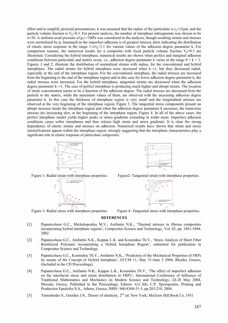
187
effort and to simplify pictorial presentations, it was assumed that the radius of the particulate is rp=15μm, and the particle volume fraction is Vp=0.3. For present analysis, the number of interphase subsegments was chosen to be n=30. A uniform axial pressure of po=-1MPa was considered in the analysis, though resulting strains and stresses were normalized by po Inasmuch as the imperfect adhesion is of greatest interest, plots indicating the distribution of elastic stress response in the range 1<r/rp<1.1 for various values of the adhesion degree parameter k. For comparison reasons, the numerical results for a composite with fixed particle volume fraction Vp=0.3 are illustrated. Considering the hybrid interphase, numerical results are shown when perfect and marginal adhesion conditions between particulate and matrix occur, i.e., adhesion degree parameter k varies in the range 0 < k < 1. Figures 1 and 2, illustrate the distribution of normalized strains with radius, for the conventional and hybrid interphases. The radial strains for hybrid interphase were increased when k→1, but they decreased radial, especially at the end of the interphase region. For the conventional interphase, the radial stresses are increased from the beginning to the end of the interphase region and in this case for lower adhesion degree parameter k, the radial stresses were increased. For the hybrid interphase, tangential strains are decreased when the adhesion degree parameter k→1. The case of perfect interphase is producing much higher and abrupt strains. The location of strain concentration seems to be a function of the adhesion degree. The radial stresses are decreased from the particle to the matrix, while the maximum values of them, are observed with the increasing adhesion degree parameter k. In this case the thickness of interphase region is very small and the longitudinal stresses are observed at the very beginning of the interphase region, Figure 3. The tangential stress components present an abrupt increase inside the interphase region and when the adhesion degree parameter k increases, the transverse stresses are increasing also, at the beginning of the interphase region, Figure 4. In all of the above cases, the perfect interphase model yields higher peaks or stress gradients extending in wider areas. Imperfect adhesion conditions cause softer interphases and thus release high strain and stress gradients. It is clear the strong dependence of elastic strains and stresses on adhesion. Numerical results have shown that strain and stress intensifications appear within the interphase region, strongly suggesting that the interphase characteristics play a significant role in elastic response of particulate composites.
Figure 1- Radial strain with interphase properties. Figure2- Tangential strain with interphase properties.
Figure 3- Radial stress with interphase properties. Figure 4- Tangential stress with interphase properties.
REFERENCES
[1] Papanicolaou G.C., Michalopoulou M.V., Anifantis N.K., ‘Thermal stresses in fibrous composites incorporating hybrid interphase regions’, Composites Science and Technology, Vol. 62, pp. 1881-1894, 2002.
[2] Papanicolaou G.C., Anifantis N.K., Keppas L.K. and Kosmidou Th.V., ‘Stress Analysis of Short Fiber Reinforced Polymers incorporating a Hybrid Interphase Region’, submitted for publication in Composites Science and Technology.
[3] Papanicolaou G.C., Kosmidou Th.V., Anifantis N.K., ‘Prediction of the Mechanical Properties of FRPs by means of the Concept of Hybrid Interphase’, ECCM 11, May 31-June 3 2004, Rhodes, Greece, (Included in the CD Proceedings).
[4] Papanicolaou G.C., Anifantis N.K., Keppas L.K., Kosmidou Th.V., ‘The effect of imperfect adhesion on the interfacial stress and strain distribution in FRP's’, International Conference of Influence of Traditional Mathematics and Mechanics on Modern Science and Technology, 24-28 May 2004, Messini, Greece, Published in the Proceedings, Editors: G.C.Sih, C.P. Spyropoulos, Printing and Production Eptalofos S.A., Athens, Greece, ISBN: 960-8360-31-5, pp.203-210, 2004.
[5] Timoshenko S., Goodier J.N., Theory of elasticity, 2nd ed. New York, McGraw Hill Book Co, 1951

189
AUTHOR INDEX A
Adda-Bedia, EA................................................. 127 Aiello, MA ................................................... 90, 120 Allegri, G ............................................................. 68 Allix, O .............................................................. 182 Almeida, P.......................................................... 150 Almeida, SFM.................................................... 164 Andrade-Campos, A....................... 60, 94, 118, 151 Anifantis, NK..................................................... 186 Aoki, Y................................................................. 70 Arafath, ARA......................................................... 4 Argüelles, A ......................................................... 92 Arrese, A............................................................ 148 Asp, LE .......................................................... 52, 66
B
Balandraud, X ............................................ 110, 132 Baley, C ....................................................... 43, 119 Balmès, E ........................................................... 122 Baraibar, I ............................................................ 92 Baral, N................................................................ 43 Bardaro, D............................................................ 27 Barroso, JM.......................................................... 58 Batiste, D ..................................................... 40, 110 Berggreen, C ........................................................ 50 Bernardo, FJ......................................................... 58 Blanco, N ................................................. 16, 52, 92 Bonhôte, P............................................................ 25 Botsis, J .................................................... 8, 25, 174 Boualem, N ........................................................ 154 Branner, K............................................................ 46 Broughton, W..................................................... 143
C
Cabrerizo, F.......................................................... 92 Camanho, PP...........................12, 87, 139, 172, 178 Carbajal, N ......................................................... 148 Cartié, D............................................................... 43 Cartié, DD............................................................ 68 Cecchini, LS....................................................... 135 Cléro, F .............................................................. 122 Cluzel, C ............................................................ 182 Corbella, B ........................................................... 92 Correa, E .............................................................. 79 Corvaglia, P.................................................... 27, 90 Costa, J........................................16, 34, 52, 92, 178 Crocker, L .......................................................... 143 Cugnoni, J .......................................................... 162 Cunningham, PR .................................................. 84 Curnier, A .............................................................. 2
D
Davies, P ...................................................... 43, 119 Dávila, CG ........................................... 12, 172, 178
Dell’Anno, G ....................................................... 68 Derrien, K .......................................................... 110 Dolto, G ............................................................. 119 Dourado, N......................................................... 146 Dulieu-Barton, JM ............................................... 84 Dumontet, H......................................................... 82 Dunkel, G............................................................... 8
E
Edgren, F.............................................................. 66 Eitzenberger, J ..................................................... 98 Elliott, B............................................................. 103 Emery, TR............................................................ 84 Esnault, R........................................................... 141
F
Faria, H ........................................................ 19, 124 Feih, S .................................................................. 30 Fernández-Canteli, A ........................................... 92 Ferreira, AJM..................................................... 126 Filipe, VM............................................................ 58 Florens, C........................................................... 122 Fortunato, A......................................................... 90 Fouinneteau, MRC............................................. 108 Freitas, M............................................................. 36
G
Gamstedt, EK................................................. 52, 79 Gibney, A........................................................... 100 Gibson, AG .......................................................... 30 Gilchrist, MD..................................................... 100 Gmür, T.................................................25, 162, 174 González, E.......................................................... 34 Gower, M........................................................... 143 Grédiac, M ............................................14, 110, 132 Green, B............................................................. 112 Guedes, RM ................................................. 19, 124 Gürdal, Z.............................................................. 87
H
Haghshenas, M................................................... 156 Hähnel, F............................................................ 168 Hamida, AB ......................................................... 82 Hartung, D ......................................................... 134 Hendriksen, PV.................................................. 153 Humbert, L............................................................. 8
I
Iannucci, L ........................................................... 32 Ishikawa, T................................................... 70, 116 Ivanov, D ........................................................... 130 Iwahori, Y .......................................................... 116

190
J
Jacobsen, TK...................................................... 176 Jensen, FM ......................................................... 135 Jesus, AM............................................................. 58 Joffe, R................................................................. 64 Johnson, AF ....................................................... 184 Jones, F ........................................................ 21, 106 Jones, S .................................................................. 6
K
Kärger, L............................................................ 134 Kawai, M.............................................................. 77 Kim, JH................................................................ 14 Kintscher, M ...................................................... 134 Koizumi, M.......................................................... 77 Kosmidou, TV.................................................... 186
L
Lapczyk, I .......................................................... 102 Leite, M.............................................................. 150 Lomov, SV......................................................... 130 Lopes, CS............................................................. 87 Lopes, J .............................................................. 150 Lund, E............................................................... 139 Lundsgaard-Larsen, C.......................................... 50
M
Maffezzoli, A ..................................................... 120 Maimí, P............................................................... 12 Manni, O ........................................................ 27, 90 Marat-Mendes, R ................................................. 36 Marques, AT .............................................. 124, 126 Mathias, JD ........................................................ 132 Mathys, Z ............................................................. 30 Matter, M ........................................................... 162 Mattsson, D.......................................................... 64 Mayugo, JA.................................................... 12, 16 McGregor, C ........................................................ 17 McNally, C......................................................... 100 Megnis, M............................................................ 98 Mieres, JM ........................................................... 85 Minak, G .............................................................. 23 Modarelli, R ......................................................... 27 Molimard, J .......................................................... 41 Mollenhauer, D .................................................. 138 Morais, J............................................................. 146 Morais, JJ ............................................................. 58 Moreira, RAS....................................................... 88 Morel, S ............................................................. 146 Moura, MFSF............................................... 19, 146 Mouritz, AP.......................................................... 30 Moutrille, MP..................................................... 110 Mujika, F............................................................ 148
N
Nagao, Y .............................................................. 70 Nóvoa, PJRO...................................................... 126
O
Oestergaard, RC................................................... 50 Oliveira, JA.....................................60, 94, 118, 151 Olsson, R.............................................................. 54 Overgaard, LCT ................................................. 139
P
Pagnotta, L ........................................................... 56 Palerosi, AC....................................................... 164 Papanicolaou, GC .............................................. 186 Pappadà, S.......................................................... 120 París, F ................................................................. 79 Partridge, I ........................................................... 68 Pedone, F ............................................................. 90 Pentecôte, N....................................................... 184 Perrot, Y............................................................. 119 Petrinic, N .......................................................... 103 Picken, SJ............................................................. 48 Pickett, AK......................................................... 108 Pierron, F ..................................................... 14, 112 Pinho, ST ............................................................. 32 Pinho-da-Cruz, J .............................60, 94, 118, 151 Pintado, JM .......................................................... 92 Pochiraju, KV ...................................................... 75 Poec, SML ......................................................... 141 Potter, K..................................................6, 158, 166 Poursartip, A .............................................4, 17, 156 Prendes, P ............................................................ 85 Prenleloup, A ....................................................... 25 Primo, T ............................................................... 27
R
Rametta, R ......................................................... 120 Reis, L................................................................ 150 Renart, J ............................................................... 34 Rezai, A ............................................................... 68 Ribeiro, MCS..................................................... 126 Robinson, P.................................................... 32, 74 Roca, P................................................................. 85 Rodrigues, JD....................................................... 88 Romera, JM........................................................ 148
S
San-José, JT ......................................................... 85 Schoeppner, GA................................................... 75 Schorderet, A ..................................................... 162 Sekulic, A .............................................................. 2 Sereir, Z ......................................................127, 154 Setchell, C.......................................................... 166 Shaw, R.............................................................. 143 Silva, A .............................................................. 150 Sorelli, LG ......................................................... 100 Sørensen, BF.........................................50, 153, 176 Sorensen, L ........................................................ 174 Stang, H ............................................................. 135 Stigliano, G .......................................................... 56 Sweeting, R.......................................................... 30

191
Syed-Muhamad, K ............................................... 14
T
Tabaković, A...................................................... 100 Tandon, GP .......................................................... 75 Teixeira-Dias, F ............................. 60, 94, 118, 151 Toftegaard, H ..................................................... 153 Toussaint, E.......................................................... 14 Trias, D ................................................................ 16 Turon, A......................................... 16, 34, 172, 178
V
Valentin, G......................................................... 146 Varna, J ................................................................ 98 Vautrin, A ............................................................ 41 Vaziri, R................................................... 4, 17, 156 Vernet, D............................................................ 182 Verpoest, I.......................................................... 130
Vicens, J............................................................... 92 Viña, J .................................................................. 92 Vlasveld, DPN ..................................................... 48
W
Wang, FH........................................................... 153 Watanabe, N....................................................... 116 Weaver, PM ....................................................... 135 Wetzel, A ........................................................... 134 Wiegand, J ......................................................... 103 Wisnom, MR.............................................6, 14, 112 Wolf, K .............................................................. 168
Z
Zhao, F......................................................... 21, 106 Zisman, A .......................................................... 130 Zouari, R .............................................................. 82 Zucchelli, A ......................................................... 23