composite steel - concrete design. a comparison · composite steel - concrete design. a comparison...
TRANSCRIPT

I I I I I I I I I I I I I I I I I I I
COMPOSITE STEEL - CONCRETE DESIGN. A COMPARISON
OF THE MONOGRAPH ON TALL BUILDINGS, AISC-ACI,
BS5400 AND THE GERMAN CODE OF PRACTICE FOR THE
DESIGN OF STEEL COMPOSITE BEAMS.
by
AH-KUM PANG
Department of Civil Engineering
Lehigh University
Bethlehem, Pennsylvania
May 1979
Fritz Engineering Laboratory Report No. 440.4

I I I I I I I I I I I I I I I I I I I
440.4 ii
ABSTRACT
Composite steel-concrete construction is quite common in various
countries especially the U.S.A., Japan and the European countries.
Each of these countries have their own specifications governing
the design and construction of composite structures. This report
presents the results of a comparative study of the provisions of the
codes and specifications of several of these countries- U.S.A.,
United Kingdom and Germany. These provisions cover the design of
composite beams both simply supported and continuous, encased beams,
composite box girders, composite columns and formed metal deck. The
codes do not all have exactly corresponding clauses but in general,
most of the relevant areas in composite design like beam and column
design are adequately covered by the various codes. Short notes are
supplied to clarify or explain certain clauses and also to indicate
the relevant research leading to the adoption of a particular clause.
To illustrate the differences between the codes, two design
examples, one on beam design and the other on column design are
worked out using the American and British codes. In column design
the second example indicates that though the design methods are quite
different, nevertheless the final designs by both methods do not
differ appreciably.
I I I I I I I I I I I I I I I I I I I
440.4 iii.
TABLE OF CONTENTS
ABSTRACT
1. INTRODUCTION
2. COMPARISON OF SPECIFICATIONS
2.1 Method of Design
2.2 Allowable Stresses
2.3 Principal Stresses
2.4 Effective Width of Concrete Flange
2.5 Control of Cracking
2.6 Longitudinal Shear
2.6.1 Method of Calculation
2.6.2 Shear Connector Strength
2.6.3 Shear Connector Tests
2.6.4 Shear Connector Design
2.6.5 Shear Connector Uplift
2.6.7 General Requirements for Connectors
2.6.8 Friction Grip Bolts as Connectors
2.6.9 Interaction with Transverse Bending
2.7 End Regions of Beams
2.8 Hannches
2.9 Temperature Effects
2.10 Shrinkage and Creep Effects
2.11 Deflection
2.12 Calculation of Loads
Page
ii
1.
4.
5.
7.
11.
11.
13.
15.
15.
17.
21.
23.
27.
31.
31.
35.
41.
41.
43.
49.
51.
53.

I I I I I I I I I I I I I I I I I I
I I
440.4 iv.
2.13 Compact and Slender Sections
2.14 Strength of Sections
2.14.1 Ultimate Moment of Resistance
2.14.2 Vertical Shear Strength
2.14.3 Influence of Vertical Shear on Ultimate Moment
2.15 Encased Beams
2.15.1 General
2.15.2
2.15.3
2.15.4
2.15.5
Longitudinal Bending Stresses
Longitudinal Shear
Temperature and Shrinkage Effects
Cracking
2.15.6 Cover
2.16 Composite Box Girders
2.16.1 General
2.16.2 Shear Connector Design
2.16.3 Connector Spacing
2.16.4 Torsion
2.17 Permanent Formwork
2.17.1 Structurally Participating
2.17.2 Steel Deck, Ribs Perpendicular to Beam
2.17.3 Steel Deck, Ribs Parallel to Beam
2.18 Composite Columns
2.18.1 Materials
2.18.2
2.18.3
Shear Connection
Concrete Controbution Factor
Page
59.
63.
63.
65.
6 7.
6 7.
67.
69.
69.
73.
73.
75.
75.
75.
77.
79.
79.
79.
79.
83.
85.
85.
85.
89.
89.
I I I I I I I I I I I I I I I I I I I
440.4 v.
2.18.4 Moments and Forces 91.
2.18.5 Effective Lengths 95.
2.18.6 Slenderness Functions 97.
2.18.7 Equivalent Radius of Gyration 99.
2.18.8 Axially Load Columns 99.
2.18.9 Columns in Bending 101.
2.18.10 Combined Axial Load, Bending and Shear 105.
2.18.11 Cracking 107.
2.18.12 Lateral R linforcement 107.
2.18.13 Creep and Shrinkage Effects 109.
3. DESIGN EXAMPLES 113.
3.1 Composite Beam Design 114.
3.2 Composite Column Design 127.
4. APPENDICES 137.
1. Effective Breadth Ratios (BS5400) 138.
2. Bar Spacings to S ±isfy Crack Limitations (BS5400) 141.
3A. Strength of Connectors (BS5400) 142.
3B. Strength of Connectors (AISC) 144.
3C. Strength of Connectors (German Code) 145.
4. Critical Shear Planes (BS5400) 149.
5. Effective Length F.ctors (ACI) 150.
6. Ultimate Moment of Resistance of Composite 151. Columns (BS5400)
7. Nomenclature 152.
5. REFERENCES 163.
6. ACKNOWLEDGEMENTS 165.

I I I I I I I I I I I I I I I I I I I
440.4 1.·
1. INTRODUCTION
Composite or mixed construction can, in general, refer to any form
of construction in which two or more different structural materials are
bonded together by some means to serve as a structural unit in
resisting loads. Thus reinforced concrete and prestressed concrete
can be considered to be forms of composite construction in that two
different materials, steel and concrete, are used together as a
structural unit. Another example of a composite material is
prestressed concrete used in conjunction with cast-in-situ concrete
in beams. However, the term composite construction is most commonly
associated with that type of construction in which steel and concrete
elements which are structural members by themselves are used together.
For example a concrete-filled tubular column is called a composite
column because either the steel tube or concrete alone can carry an
applied load. This feature distinguishes it from reinforced or
prestressed concrete in which the steel is not a structural member
but only serves as reinforcing tendons.
Research in composite structures began in the beginning of this
century. Early tests were done on fully encased rolled beams in Canada
in 1923. Since its introduction in the 1950's, the stud connector
has become the most common and widely used type of shear connection.
Nowadays research in composite construction is concentrated in areas
like composite walls, connections, frames and structurally participating
formwork.

I I I I I I I I I I I I I I I I I
'I I
440.4 2.
From the knowledge gained from the past research, many countries
now have codes and specifications setting out the design and construction
requirements for this form of construction. These provisions are
different in different countries. With this in mind, the purpose of
this report is to make a comparison of the different approaches to
composite design of several countries. The study considers the back
ground research leading to the .adoption of specific provisions, the
design philosophy of each code, factors of safety and other aspects.
This will serve to highlight areas where more research is needed to
lead to more economical design and it is also hoped that it will be
useful to engineers and researchers. The codes and specifications
chosen for th{s comparative study are:
1. AISC Specification (Ref. 3)
2. ACI Building Code (Ref. 1)
3. British Code BS5400: Part 5 (Ref. 6)
4. German Code ( Ref. 16)
In addition, Chapter SB-9 on Mixed Construction of Volume SB of the
MONOGRAPH on Tall Buildings was also included. The MONOGRAPH is a
major treatise on the latest developments in the planning, design
and construction of tall buildings, produced under the auspices of
the Council on Tall Buildings and Urban Habitat, headquartered at
Lehigh University, Bethlehem, Pennsylvania. It is not a design
specification but nevertheless it has been considered because it
provides information on past and present research in composite
construction and also design proposals put forward by researchers and
engineers in this field.
I I I I I I I I I I I I I I I I I I I
440.4 3.
The ACI Building Code provisions for composite columns (which are
basically treated as reinforced columns) supplt~ment the AISC rules
which apply only to composite beams and formed steel deck. Therefore
in the section on composite columns, the ACI Code is used in place
of the AISC Specification. As for the German rules for composite
columns, these are given in a separate code which was unavailable at the
time of preparation of this report. It is hoped that this can be
rectified in the future.
Two design examples, one on composite beam design and the other
on composite column design, are provided. These are designed using
the provisions of the American and British codes in order to illustrate
the different design approach of each. For composite beam design, the
AISC specification calls for a working stress design while BS5400
uses limit state approach. The ultimate limit state is usually
designed for first and then serviceability limit states are checked.
In composite column design, the methods adopted by the ACI Code and
BS5400 are fundamentally different methods. The ACI Code employs a
moment magnifying factor to account for slenderness effects whereas in
BS5400, the moment-thrust interaction curve is obtained for each
case of slenderness. However, the final design from both methods do
not differ appreciably. The reader is referred to Chapter 4 of this
report for details of the design calculations.
I 440.4 4 ..
I I 2. COMPARISON OF SPECIFICATIONS
I I I I I I I I I I
I I
I I I I I
440.4
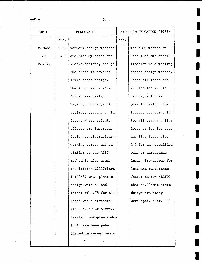
TOPIC
Method
of
Design
Art.
9.2-
4·
5.
MONOGRAPH' AISC SPECIFICATION (1978)
~ect.
Various design methods
are used by codes and
specifications, though
the trend is towards
limit state design.
The AISC used a work
ing stress design
bas~d on concepts of
ultimate strength. In
Japan, where seismic
effects are important
design considerations,
working stress method
similar to the AISC
method is also used.
The British CP117:Part
1 (1965) uses plastic
design with a load
factor of 1.75 for all
loads while stresses
are checked at service
levels. European codes
that have been pub
lished in recen~ years
The AISC method in
Part 1 of the speci
fication is a working
stress design method.
Hence all loads are
service loads. In
Part 2, which is
plastic design, load
factors are used, 1.7
for all dead and live
loads or 1.3 for dead
and live loads plus
1.3 for any specified
wind or earthquake
load. Provisions for
load and resistance
factor design (LRFD)
that is, limit state
design are being
developed. (Ref. 11)
I I I I I I I I I I I I I II
I I .I
I I

I I I I I I I I I I I I I I I I I I I
440.4 6. '
BS5400: PART 5 (1978) GERMAN CODE (1974)
Sect. Sect.
Limit state design is Limit state design.
used with partial For load combination
safety factors for H, the factors are
loads and materials 1.7 for dead and
as follows: live loads plus 1.0
4.1. 2 Dead Load for shrinkage, temp-
Yn= 1.0 at SLS erature and settlement
= 1.4 at ULS effects if the struc-
Imposed Load ture is statically
y ·= f1 1.0 at SLS indeterminate. This
= 1.6 at ULS last factor is in-
Shrinkage modified by creased to 1.3 when
creep considering end
Yn= 1.0 at SLS regions of beams.
= 1.2 at ULS Load combination HZ
4.1. 3 Design Loading Effects (1.5 times the sum of
Yn= 1.0 at SLS dead and imposed
= 1.1 at ULS loads) should also be
For materials: considered if
4.2.1 Structural Steel necessary.
y = 1.0 at SLS m
= 1.10 at ULS
Reinforcement
y = 1.0 at SLS m
= 1.15 at ULS
Materials:
No partial factors of
safety for materials
are given.
NOTES
BS5400:
SLS and ULS
~eans ser-
!Viceab ili ty
and ultimate
limit states.
440.4 7.
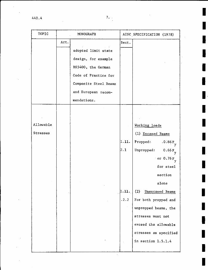
TOPIC MONOGRAPH
Art.
adopted limit state
design, for example
BS5400, the German
Code of Practice for
Composite Steel Beams
and European recom-
mendations.
Allowable
Stresses
AISC SPECIFICATION (1978)
Sect.
Working loads
(1) Encased Beams
1.11. Propped: ,0~66:F y
2.1 Unpropped: 0.66F y
·or 0. 76 F y
for steel
section
alone
1.11 •. (2) Unencased Beams
.2.2 For both propped and
unpropped beams, the
stresses must not
exceed the allowable
stresses as specified
in section 1.5.1.4
I I I I I I
I" I I I I I I I I I I I I
I I I I I I I I I I I I I I I I I I I
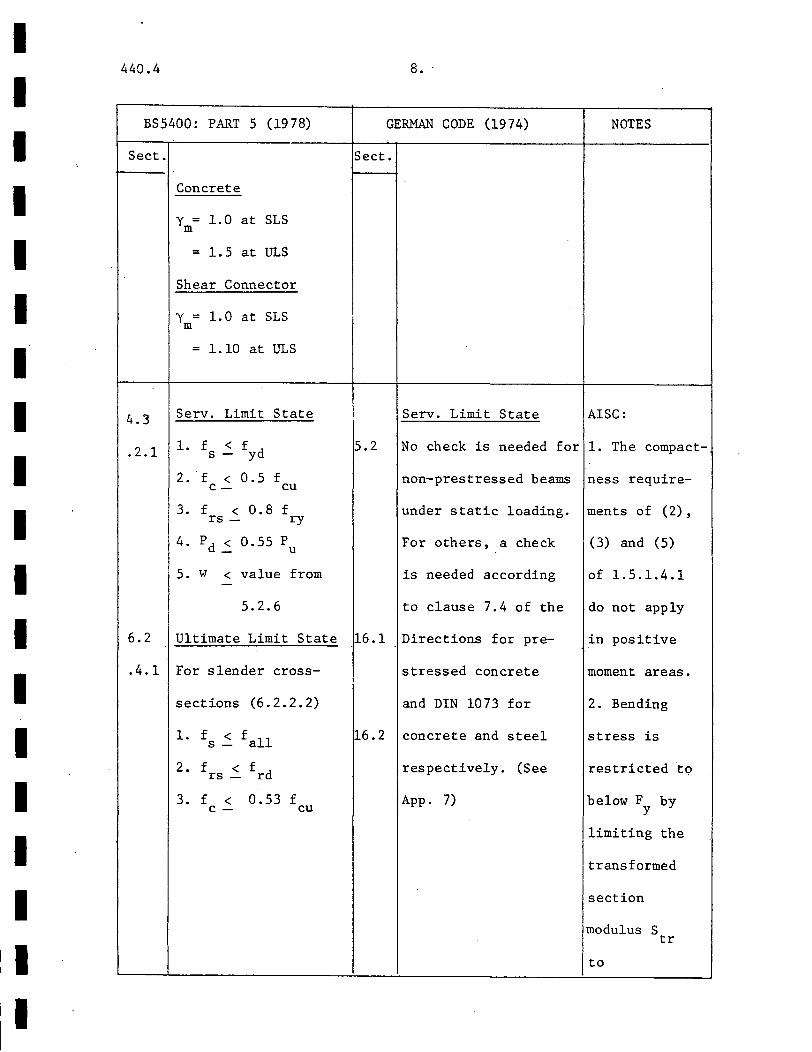
440.4
BS5400: PART 5 (1978)
Sect.
4.3
.2.1
6.2
.4.1
Concrete
y = 1.0 at SLS m
= 1.5 at ULS
Shear Connector
y = 1. 0 at SLS m
= 1.10 at ULS
Serv. Limit State
1. f < fyd s-
2. f < 0.5 f C- cu
3. f < 0.8 f rs- ry
4. pd ~ 0.55 Pu
5. w < value from -
5.2.6
Ultimate Limit State
For slender cross-
sections (6.2.2.2)
1. f < f s- all
2. f < frd rs-
3. f < 0.53 f c- cu
8 •.
GERMAN CODE (1974) NOTES
Sect.
Serv. Limit State AISC:
5.2 No check is needed for 1. The compact-
16.1
~6.2
non-prestressed beams ness require-
under static loading. ments of (2),
For others, a check (3) and (5)
is needed according of 1.5.1.4.1
to clause 7.4 of the
Directions for pre-
stressed concrete
and DIN 1073 for
concrete and steel
respectively. (See
App. 7)
do not apply
in positive
moment areas.
2. Bending
stress is
restricted t<;>
below F by y
limiting the
transformed
section
modulus S tr
to

440.4 9.
TOPIC MONOGRAPH
Art.
AISC SPECIFICATION (1978)
Sect.
1.5 Compact Section
.1.4 Fb equals smaller of
0.66F or y
Fy[.79- .002(bf/2tf)~]
(1. 5-5a)
Other Sections
Compression:
(102 x 10 3Cb/F) 1
/2 < L/r
y - t
2 (510 X 10 3Cb/Fy) 112
2 (L/rt) 2 1\= ( 3- 1530 X 10 3 C )F
b y
(1. 5-6a)
L/r~ (510 x 10 3Cb/Fy) 1
/2
170 X 103Cb (1.5-6b)
Fb = (L/rt)2
Tension:
Concrete
f < 0.45£ 1
c - c
I I I I I I I I I I I I I I I I I I I
I I I I I I I I I I I I I I I I I I I
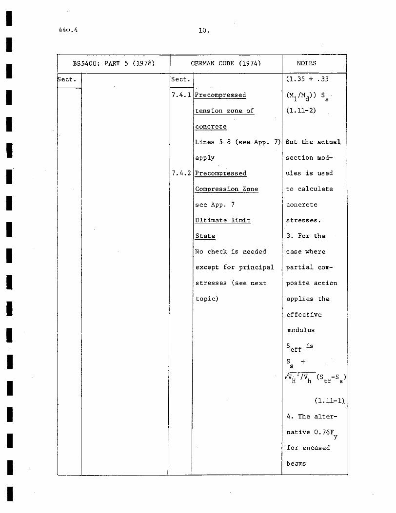
440.4
BS5400: PART 5 (1978)
Sect. Sect.
7.4.1
7.4.2
10.
GERMAN CODE (1974)
Precompressed
tension zone of
concrete
Lines 5-8 (see App.
apply
Precompressed
Compression Zone
see App. 7
Ultimate limit
State
No check is needed
except for principal
stresses (see next
topic)
I
NOTES
(1.35 + .35
(Ml/Md)) s s
(1.11-2)
7) But the actual
section mod-
ules is used
to calculate
concrete
stresses.
3. For the
case where
partial com-
posite action
applies the
effective
modulus
seff is
s + s
/VH I /Vh (st -s ) r · s
(1.11-1)
4. The alter-
native 0.76F y
for encased
beams
440.4 11.
TOPIC MONOGRAPH AISC
Art. ~ect.
Principal
Stresses
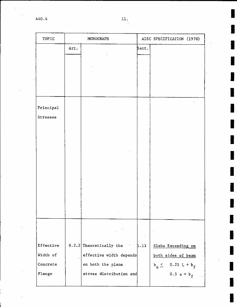
Effective 9.2.2 Theoretically the ~.11
Width of effective width depends
Concrete on both the plane
Flange stress distribution and
SPECIFICATION (1978)
Slabs Extending on
both sides of beam
b < 0.25 L+bf e-
0.5 a+ bf
I I I I I I I I I I I I I I I I I I I
I I I I I I I I I I I I
I I I I I
440.4 12.
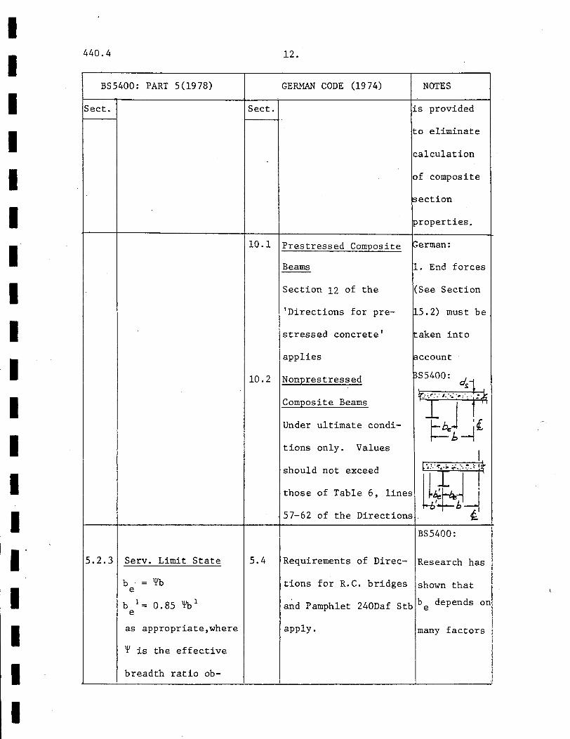
BS5400: PART 5(1978) GERMAN CODE (1974) NOTES
Sect. Sect. is provided
to eliminate
calculation
of composite
jsection
properties. r----r----------------~---4------------------~--------~-
5.2.3 Serv. Limit State
b = 'f'b e
b 1 = 0. 85 '¥b 1
e
as appropriate,where
'¥ is the effective
breadth ratio ob-
10.1 Prestres·sed Composite ~erman:
10.2
5.4
Beams 1. End forces
Section 12 of the (See Section
'Directions for pre- 15.2) must be
stressed concrete' aken into
applies F!ccount
Nonprestressed
Composite Beams
Under ultimate condi-
tions only. Values
should not exceed [·,;:1:,.:.:·.:::.•· tt those of Table 6, lines ~~~~ 57-62 of the Directions . t
BS5400:
Requirements of Direc- Research has
tions for R.C. bridges shown that
and Pamphlet 240Daf Stb be depends on
apply. many factors
440.4 13.
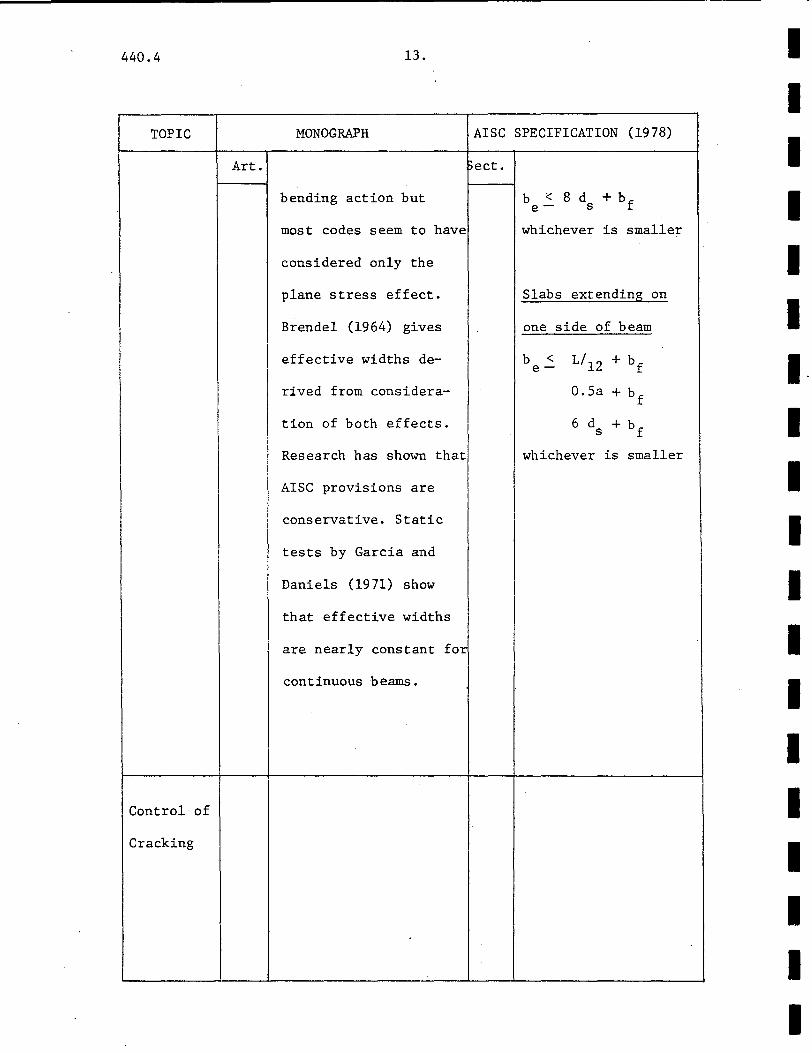
TOPIC MONOGRAPH
Art.
bending action but
most codes seem to have
considered only the
plane stress effect.
Brendel (1964) gives
I effective widths de-
rived from considera-
tion of both effects.
Research has shown that
AISC provisions are
I conservative. Static
tests by Garcia and
Daniels (1971) show
that effective widths
are nearly constant fat
continuous beams.
Control of
Cracking
AISC SPECIFICATION (1978)
Sect.
b < 8 d + bf e- s
whichever is smaller
Slabs extending on
one side of beam
b < L/12 + bf e-
O.Sa + bf
6 d + bf s
whichever is smaller
I I I I I I I I I I I I I I I I
I I

I I I I I I I I I I I I I I I I I I I
440.4
BS5400; PART 5 (1978)
Sect.
6.2
.3.1
5.2
.6.3
tained from Tables
2,3 or 4.
(see App.l)
Ultimate Limit State
For compact sections
be= L/6 < bf
For slender sections
5.2.3 applies
Allowable Crack
Widths
Condition
Moderate
Severe
Very Severe
wall
0.25nun
0.20mm
O.lOmm
14.
GERMAN CODE (1974)
Sect.
Prestressed Beams
9.1.1 Check for permissible
stresses and provide
9.1.2 tensile reinforcement
in accordance with
the Directions for
NOTES
like b/L ratio
type of load-
ing, boundary
conditions
and others
(Ref. 12)
2. An end span
of a contin-
uous beam is
t'reated as an
equivalent
simple span of
0.91.
3. If' at an
internal
support is
taken on the
mean for the
adjacent spans. _
BS5400:
This clause
applies if
nominal cover
to the rein-
forcement is
440.4 15.
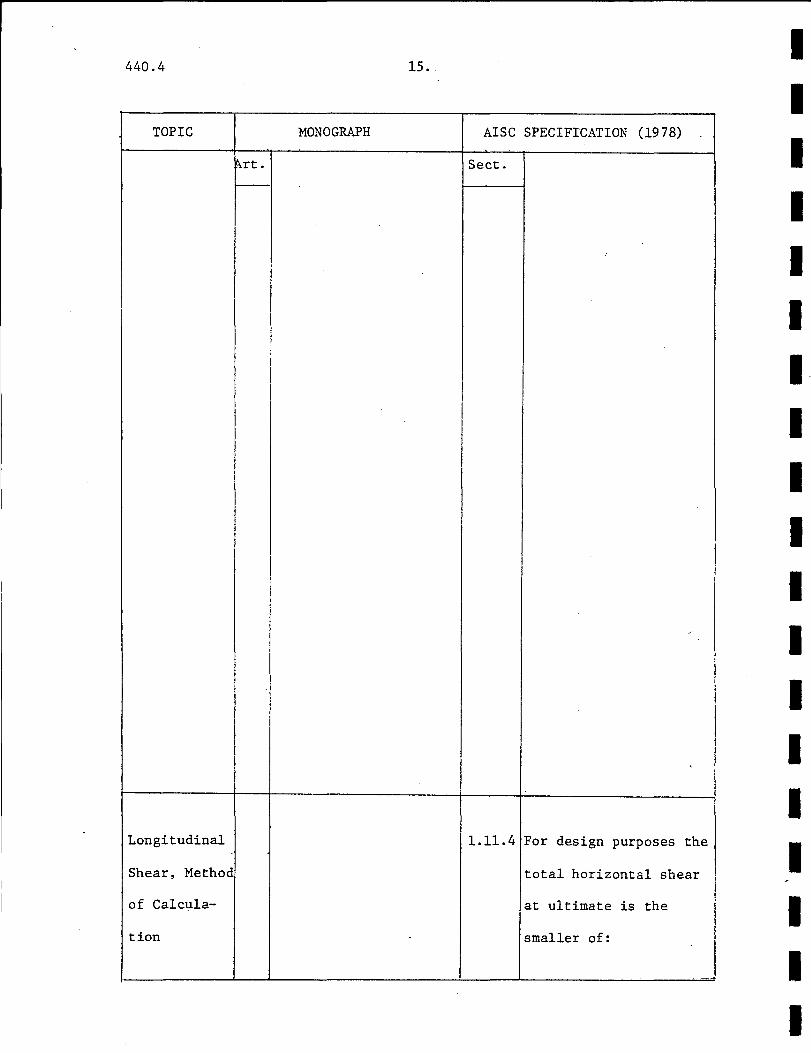
TOPIC MONOGRAPH AISC
~rt. Sect. f--
I
Longitudinal 1.11.4
Shear, Method
of Calcula-
tion
SPECIFICATION (1978)
/
'
For design purposes the
total horizontal shear
at ultimate is the
smaller of:
I I I I I I I. I I I I I I I I I I I I
I I I I I I I I I I I I I I I I I
I I
I
440.4 16.
BS5400: PART 5 (1978) GERMAN CODE (1974) NOTES
Sect.
5.2.
Sect.
A method for the cal- prestressed concrete not greater
culation of crack and R.C. bridges than 30mm.
widths is given in Bars with
Appendix B. Non-Prestressed Beams. diameter less
Alternatively, re- 9.2.1 Clause 17.6.2 of DIN than 0.45 times
inforcement provided 1045 applies unless the diameter
in accordance with the following condi- of the largest
5.2.6.4 may be deemed tions are satisfied. bar should be
to satisfy crack
control requirements
(See App. 2)
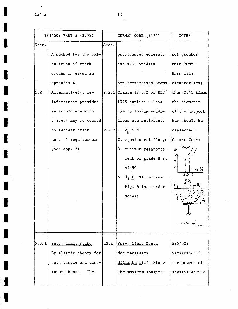
9.2.2 1. vh < d neglected.
2. equal steel flanges German Code:
3. minimum reinforce-
ment of grade B st
42/50
4. d~ < value from e-
Fig. 6 (see under
Notes)
2o decmm)
15 /
10
5
·3-5 ·7
§u"l m:l') rllr
' .. · ........... . ·.-.: · •. ' :-: ···~.:;.·· ·.r· .. . . ... ... ··~ ..
•. ·: ·· .. .'~ ~ • , ~ ;. ·.• n
T F/Gr. G
5.3.1 Serv. Limit State 12.1 Serv. Limit State BS5400:
By elastic theory for Not necessary Variation of
both simple and cont- Ultimate Limit State the moment of
inuous beams. The The maximum longitu~ inertia should

440.4 17. I I
TOPIC MONOGRAPH AISC SPECIFICATION (1978)
I Art. Sect.
0.85f1A /2 c c (1.11-3) I A F /2 s y (1.11-4)
for simple beams and I A F /2 for con tin-sr yr
I I uous beams. The term
I A 1 F /2 should be I I s y
I added to equation I
' (1.11-3) if longitu- I I I I
dinal steel A 1 is s
I located within the ;
i effective width. I I
I I
I I I
I
I Longitudinal 9.2-4 Studs in flat soffit 1.11.4 Static Strength I Shear, Slabs The allowable load per
I Shear Q = ~ O.SA If E connector, q, is ob-u s c c
Connector I
(9 .11) tained from Table 1.
I Strength I for H /D > 4 11.4 for flat soffit I
I s s-
~ is usually 0.85 slabs with ASTM C33 I Studs in Steel Deck aggregates (see App.
A reduction factor is 3B) and modified by I I I
I I I I I I I I I I I I I I I I I
I
440.4 18.
BS5400: PART 5 (1978) GERMAN CODE (1974) NOTES
Sect. . Sect.
effective width, dinal shear forces may be taken into
assumed constant, is be determined from the account in
taken as the quarter-
span value for UDL
from Tables 2 and 4
for simply supported
and continuous beams
and the support value
for UDL from Table 3
for cantilevers.
6.3.1 Ultimate Limit State
Same as above but with
loading corresponding
to ULS.
5.3.2 Static Strength
.1 The nominal static
strength P is obtainu
ed from Table 8 (see
App. 3A) for normal
concrete.
5.3.2 For lightweight
.2 concrete, reduce by
15%, Table 8 also
applies to haunched
calculation of ulti- calculating
mate strength from the shear
sections 6.3 and 6.4. flow.
German Code:
The calculated value 1. The same
is reduced as follows: requirement
V = V (:H/!1 ) p p as above
applies
2. Bond
between
concrete and
steel is
neglected.
Static Strength BS5400:
.Formulas are given for 1. Pu for studs.
each type of connector is roughly
(see App. 3C) as proportional •
follows: to D2 and
12.2 Headed and deformed ~ headed studs 2. Haunches
12.3 Bar connectors must comply
12.4 Anchor and hook conn- with minimum
ectors dimensions to

440.4
TOPIC
Art.
19.
MONOGRAPH AISC SPECIFICATION (1978)
Sect.
usually applied to
equation 9.11. See
structurally partici-
pating formwork.
Channel connectors ~3
Q = ~ 0.3 (h + O.Stc) u c
w If 1 E c c c
Fatigue Strength
(9 .13)
Research at Lehigh
University has shown
that the fatigue
strength of stud con-
nectars depends pri-
marily on the stress
range. The influence
of dead load or min-
imum stress is minor.
(Slutter and Fisher,
1966, 1967). The stress.
range formula is:
148N- 0 • 186 ksi
(9.20 a,b)
Table 1.11.4A for ASTM
C330 aggregates.
Fatigue Strength
Appendix B specifies
allowable range of
stresses to be used
in fatigue design for
connectors. These
ranges are narrower
for increasingly
higher number of
loading cycles.
I I I I I I I I I I I I I I I I I I I
I I I I I I I I I I I I I I I I I I I
440.4
BS5400: PART 5 (1978)
Sect.
slabs complying with
section 6.3.2.1.
Fatigue Strength
Part 10 of the Stand-
ard applies for all
types of concrete.
Strengths of con-
.2.1 nectors not covered in
(3) in these sections
5.3. (or where haunches do
2.3 not comply with
6.3.2.1) are to be
determined from push-
out tests (Section
5.3.2.4 or Part 10.)
Sect.
12.5
20.
GERMAN CODE (1974) NOTES
H.S.F.G. Bolts ensure suffi-
cient lateral
constraint by
Fatigue Strength concrete to
The strength in develop the
shear and axial full capacity
tension are reduced by of the con-
1/3 for repeated nector.
loading. (NOTE: AISC:
This provision is be- 1. The formula
ing revised.) for static
strength of
studs is
Q =0 • SA: If 1 E u s c c
2. Stud con-
nector strengths
became constant
at high concrete
strengths. For
normal/light-
weight concrete,
the limits are
4.0/5.0 ksi
respectively.
440.4 21.
TOPIC MONOGRAPH
Art.
:
!Longitudinal 9. 2-3 Connector behavior in a. ! I shear, beam may differ greatly I
!shear from that in a pushout
I connector test, due to factors
Tests like different states
of stress, different
amounts of reinforce-
ment, different state
of concrete containment
Nevertheless, there is
reasonable correlation
(Chapman and Terasz-
kiewicz, 1968) and
AISC SPECIFICATION (1978)
sect.
I i I I
I
I
' i !
I I I
I I I I I I I I I I I I I I I I I I I
I I I I I I I I I I I I I
, I I I I I I
440.4 22.
BS5400: PART 5 (1978) GERMAN CODE (1974)
Sect. Sect ..
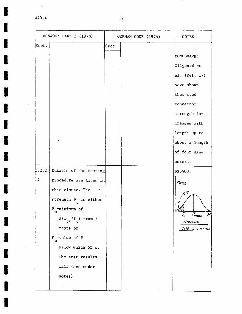
~.3.2 Details of the testing.
.4 procedure are given in
this clause. The
strength p is either u
P =minimum of u
P(f· /f ) from 3 cu c
tests or
P =value of P u
below which 5% of
the test results
fall (see under
Notes)
NOTES
MONOGRAPH:
Ollgaard et
al. (Ref. 17)
have shown
that stud
connector
strength in-
creases with
length up to
about a length
of four dia-
meters.
BS5400:
1)15TRIBUTitW
440.4 23.
TOPIC MONOGRAPH
Art.
Slutter and Driscoll,
after comparing push-
out test results with
beam .test data, have
concluded that push-
out test results can
be taken as conserva-
tive approximations to
the ultimate strength
of shear connectors
in beams.
Longitudinal 9.2-4 The AISC method that
Shear, considers both full
Shear and partial composite
Connector action is described.
Design This is based on the
work of Slutter and
Driscoll (Ref. 18) who
developed a theory of
ultimate strength of
beams with partial
shear connection. Wit[
partial shear connec-
AISC SPECIFICATION (1978)
Sect.
1.11.4 Ultimate Strength
Design
Both full and partial
composite action are
considered.
Full composite action
Vh= 0 .·85f 1 A /2 (1.11-3) c c
A F /2 (1.11-4) s y
whichever is smaller,
for simply supported
beams. For continuous
beams:
I I I I I I 1-I I I I I .I
I I I I I I
I. I I I I I I I
'I I I I I I I I
~I.
I 1:
440.4
BS5400: PART 5 (1978)
Sect.
5.3 General Procedure
.3.5 Design for SLS and
check for fatigue by
Part 10 (See also
Notes). No check at
the ULS is necessary
unless specified in
6.1.3.
Serv. Limit State
Design strength is
Pd = 0.55 Pu
Q X S ~2 p d
24.
GERMAN CODE (1974) NOTES
Sect ..
~2.1 :Ultimate Strength BS5400:
~esign 1. The size
The total number of and spacing
connectors must be must be main-
.~ufficient to transfer tained for at
ll that is: least 10% of
N = V/D > 0.5V /D s- p s
the span.
2. Section
4.3.1 states
that design
of connectors
in accordance
440.4
TOPIC
Art.
25.
MONOGRAPH
tion, stresses and
slip are increased and
there is some loss of
interaction. But
there is still adequate
reserve strength.
Other researchers
(Johnson, 1975; Stark
I and Brassinga, 1972)
have proposed design
recommendations for
I partial shear connec-
tion. Partial connec-
tion is required:
1. when strength re-
quirements can be met
by less than full com-
posite action.
2. the number of
connectors that can be
AISC SPECIFICATION (1978)
~ect.
Vh= A F /2 (1.11-5) sr yr
Partial Composite
Action:
The total horizontal
shear is:
V 1 = qN > Vh/4 h 1-
where vh is obtained
from (1.11-3) or
(1.11-4) as appro-
priate ..
accommodated is limited,
e.g. in a corrugated
steel form.
I I I I I I I I I I I I _I
I I I .I I _J
I I I . I
I I I I I I I I I I I I I I I
440.4 26.
BS5400: PART 5 (1978) GERMAN
Sect . Sect.
6.3.4 Ultimate Limit State
Need not be consider-
ed except as directed
in 5.3.3.4 and 6 .1. 3.
Then:
p = 0.8 p /Y or d u m
0.8 pljy u m
where y = 1.1 m
I
I
CODE (1974) NOTES
with Part 10
is deemed to
satisfy fatigue
aspects at SLS
3. Research
(Yam & Chapman,
1968) has shown\ I
that p = d o.sPJ
will ensure
that flexural
failure will
occur before
shear failure.
4. Full inter-
action is as-
sumed at SLS.
AISC:
The approach
is based on
the fact that
at or near
ultimate con-
dition, each
connector
440.4 27.
TOPIC MONOGRAPH AISC -
Art. Sect..
'
Longitudinal
Shear,
Shear
Connector
. Uplift
SPECIFICATION (1978)
I I
I I I I I I. I I I I I I I I I I I I

I I I I I I I I I I I I I I I
I I I
440.4
BS5400: PART 5 (1978)
Sect.
5.3
. 3. 4
If connectors are
subject to significant
tension, additional
ties should be pro-
vided or alternatively
stud connectors may be
used and checked at
the ULS and, if appl-
icable, for fatigue.
If P is reduced, and u
Q increased by more
than 10%, account
should be taken of
direct tension by
reducing P and inu
creasing Q as follows:
p 1 = p - T /~ u u u
28.
GERMAN CODE (1974) NOTES
Sect.
carries about
equal loads
due to redis-
tribution of
loads. (Ref.
18)
12.2 This clause is being BS5400:
revised. Direct tension
may arise from
1. transverse
moments acting
on the connec-
tors.
2. differential
bending of the
girder.

440.4 29. I I
TOPIC MONOGRAPH AISC SPECIFICATION (1978)
Art. Sect. I I
Longitudinal 9. 2-3 Research has shown 1.11.4 S ~2_ 6D
Shear, that uniform distribu- s > 4D t-I
Shear tion for uniform load but not to exceed 8d . s I Connector as well as uniform The distribution is
Distribution plus concentrated uniform for both simple I loads is permissible and continuous beams
I on account of the except that, for a con-I
I I
I plastic redistribution centrated load, N2 con-I
I of forces among the nectors must be between I
j I connectors at the ul- the load and the near-i I I
I timate state. est point of zero mo-
where: ment I N2 = N (MS/M - 1)
1 max s - 1 I
i
(1.11-7) I I I I I I I

I I I I I I I I I I I I I I I I I I I
440.4
BS5400: PART 5 (1978)
pect.
p. 3.
3.1
si .s. 600mm
< 3d - s i
< 4b
whichever is smaller,
except that for nega-1
tive moment regions oj
Sect.
12.1
continuous cross- 12.2
!girders, no I . connec-
ltors should be placed
within 2b of the near-
est connector on the I
lmain girder, where b i
is the flange width
of the cross-girder.
3d.
GERMAN CODE (1974) NOTES
The shear connectors BS5400:
are to be distributed Groups of
approximately in pro~ connectors are
portion to the enve- allowed pro-
lope of the vertical vided account
shear forces.
st _: Sd1
s > 2.5dl t-
is taken of
the greater
possibility
of slip and
separation
AISC:
Besides the
redistribution
of forces,
uniform
spacing also
provides for
easier detail-
ing and more
regular shear
flow.
440.4 31.
TOPIC MONOGRAPH AISC SPECIFICATION (1978)
Art. ~ect.
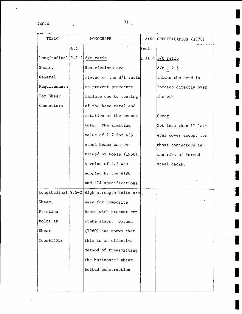
Longitudinal 9.2-2 d/t ratio .~.11.4 D/t ratio
Shear,
General
Requirements
For Shear
Connectors
Restrictions are
placed on the d/t ratio
to prevent premature
failure due to tearing
of the base metal and
rotation of the connec
ltors. The limiting
value of 2.7 for A36
steel beams was ob-
tained by Goble (1968).
A value of 2.5 was
adopted by the AISC
and AIJ specifications.
Longitudinal. 9.2-2.High strength bolts are
!Shear,
!Friction I jBolts as
Shear
Connectors
used for composite
beams with precast con-
crete slabs. Dornen
(1960) has shown that
this is an effective
method of transmitting
the horizontal shear.
Bolted construction
d/t < 2.5
unless the stud is
located directly over
the web
Cover
Not less than 111 lat-
eral cover except for
those connectors in
the ribs of formed
steel decks.
I I I I I I I I I I I I I I I I I I I
I I I I I I I I I I I I I I I I I I I
I I
I
440.4
BS5400: PART 4 (1978)
Sect.
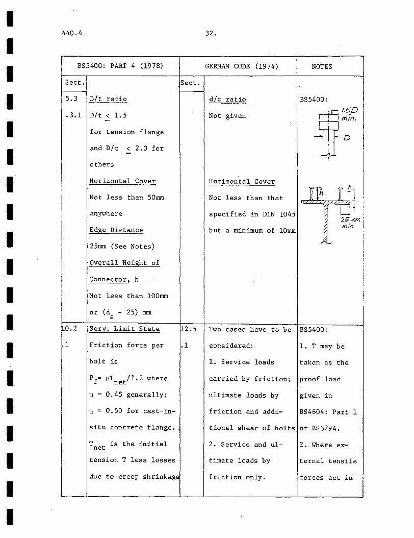
5.3 D/t ratio
.3.1 D/t < 1.5
for tension flange
and D/t < 2.0 for
others
Horizontal Cover
Not less than 50mrn
anywhere
Edge Distance
25mrn (See Notes)
Overall Height of
Connector, h
Not less than lOOmrn
or (d - 25) mrn s
Serv. Limit State
Friction force per
bolt is
Pf= ~T /1.2 where net
~ = 0.45 generally;
~ = 0.50 for cast-in-
situ concrete flange.
T t is the initial ne
tension T less losses
due to creep shrinkage
Sect.
112.5
.1
32.
GERMAN CODE (1974)
d/t ratio
Not given
Horizontal Cover
Not less than that
specified in DIN 1045
but a minimum of lOmrn
NOTES
BS5400:
d5 1.5_D m1n.
L.......-.---.J
--n-~D 4-
K!h I t1 /
/ LJT 2.S dJm' 111t'n
Two cases have to be BS5400:
considered: 1. T may be
1. Service loads taken as the
carried by friction; proof load
ultimate loads by given in
friction and addi- BS4604: Part 1
tiona! shear of bolts or BS3294.
2. Service and ul- 2. Where ex-
timate loads by ternal tensile
friction only. forces act in
440.4 33.
TOPIC MONOGRAPH
Art.
is dismountable but is
more expensive than
using stud connectors.
I
I I I
I I I
I
AISC SPECIFICATION (1978)
Sect.
l I
I i
I
I I I I I I I I I I I I I I I I I I I

I I I I I I I I I I I I I I I I I I I
440.4
BS5400: PART 5 (1978)
Sect. Sect.
effects. 12.5
10.2 Ultimate Limit State .2
• 2 Design by 10.2.1 is
deemed to satisfy ULS
requirements.
10.3 Fatigue
Need not be considerec
for connections sub-
ject to shear in the
plane of friction in-
terface.
112.5
.3
34.
GERMAN CODE (1974) NOTES
Friction at Service addition to
Loading Only shear, account
The shear flow is should be
assumed equally dis~ taken of this
tributed over a in reducing
the effective
clamping
force.
3. Adequate
addition, a check is spiral rein-
made at ULS by Sec- forcement
tion 6 or alternativ- should be pro-1
ely, check the shear- vided to
ing strength along ensure pro-
of the bolts by sec- per transfer
tion 12.2. of load with-
Friction at Service out crushing
and Ultimate Loading or splitting
Check by section 6 of concrete.
with ].1=0. 55. German:
Also check that the 1. Note 3 above
total longitudinal applies.
shear can be resisted 2. Slip, creep
by the total friction and shrinkage
440.4
TOPIC
Art.
Longitudinal . 9.2-2
Shear,
Interaction
Hith
Transverse
Bending
j
35 •.
MONOGRAPH AISC
!sect.
British Standard Code
of Practice CP117,
Parts 1 (1965) and 2
(196 7) contain rules to
ensure sufficient
strength to resist
longitudinal shear in
the vicinity of shear
connectors. Johnson
(19 70) has concluded
that these rules are
unduly conservative and.
proposed a new ultimate
strength design based
on the work on shear
transfer of Mattock
and Hawkins (1972).
BS5400 has adopted this
new method (see under
BS5400). This method
SPECIFICATION (19 78)
I I I I I I I I I I I I I I I I I I I

I I I
I I I I I I I I I I I I I I I
440.4
BS5400: PART 5 (1978)
lsect. Sect.
~.3.3 Ultimate Limit State 12.1
p.3.3
The method is appli-
cable to haunched or
unhaunched beams with
slabs of normal or
lightweight concrete.
For any shear plane,
q < k sL + .7A f p- 1 s e ry
or k L f 2 s cu
whichever is lesser
where k , k are 0.9/ 1 2
0.7 and 0.15/0.12 for
normal/lightweight
concrete.
If f < 20N/nnn, cu
k 1 sL is replaced by s
0.04/0.03 for normal/
lightweight concrete
For haunched beams:
36.
GERMAN CODE ( 19 7 4) NOTES
force of the bolts. should be
taken into
account.
The shear stress on German:
the critical plane v 'Critical shear
should not exceed the planes:
following values of
vall without shear
reinforcement must be
provided. In no case
should v e4ceed v max
below.
Concrete
Grade
Bn250
Bn350
Bn450
Bn550
v max
·· .. (kp/ cm 2)
14 55
18 70
20 80
22 90
If v exceeds vall
reinforcement is to
. 4·:.; .·· ·..:.-· J •• ;.; ••• J : f f. T ... ·i . I
I f·· :~ :.·:Q~ ·.: .·.-: :· t1
T
BS5400:
An increased
value is used
for q when p
440.4 37 .•
TOPIC MONOGRAPH AISC
Art. ~ect.
is more liberal than
the old method and
sometimes it is
I possible to omit bottom I I reinforcement altoget-I ! i
her in the slab by i I
! applying these rules.
! I
!
' l I I
I
i ;
I I I
I
I I I
.
I
j
! SPECIFICATION (1978) I
I
I I I I I I I I I I I I I I I I I I I
I I I I I I I I I I I I I I I I I I
II
440.4
TOPIC
Art.
I I i I I I
I I I
I
I
39.
MONOGRAPH AISC SPECIFICATION (1978)
Sect.
I I I
I I
440.4
BS5400: PART 5 (1978)
Sect. Sect.
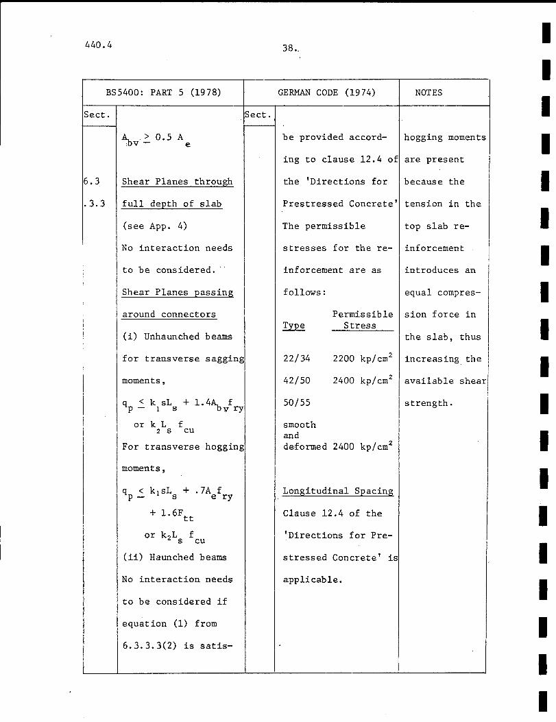
6.3 Shear Planes through
. 3. 3 full depth of slab
(see App. 4)
No interaction needs
to be considered.
Shear Planes passing
around connectors
(i) Unhaunched beams
for transverse sagging
moments,
q < k sL + 1.4~ f p- 1 s -ov ry
or k L f 2 s cu
For transverse hogging
moments,
q < k 1 sL + .7A f p - s e ry
+ 1. 6F tt
or k 2L f s cu
(ii) Haunched beams
No interaction needs
to be considered if
equation (1) from
6.3.3.3(2) is satis-
38.
GERMAN CODE (1974) NOTES
be provided accord- hogging moments
ing to clause 12.4 of are present
the 'Directions for because the
Prestressed Concrete' tension in the
The permissible top slab re-
stresses for the re- inforcement
inforcement are as introduces an
follows: equal compres-
Permissible sion force in ~ Stress
the slab, thus
22/34 2200 kp/cm2 increasing the
42/50 2400 kp/cm2 available I shear I
50/55
smooth and deformed 2400 kp/cm2
Longitudinal Spacing
Clause 12.4 of the
'Directions for Pre-
stressed Concrete' is
applicable.
strength.
I I I I I I I I I I I I I I I I I I I
I I I I I I I I I I I I I I I I I I I
440.4
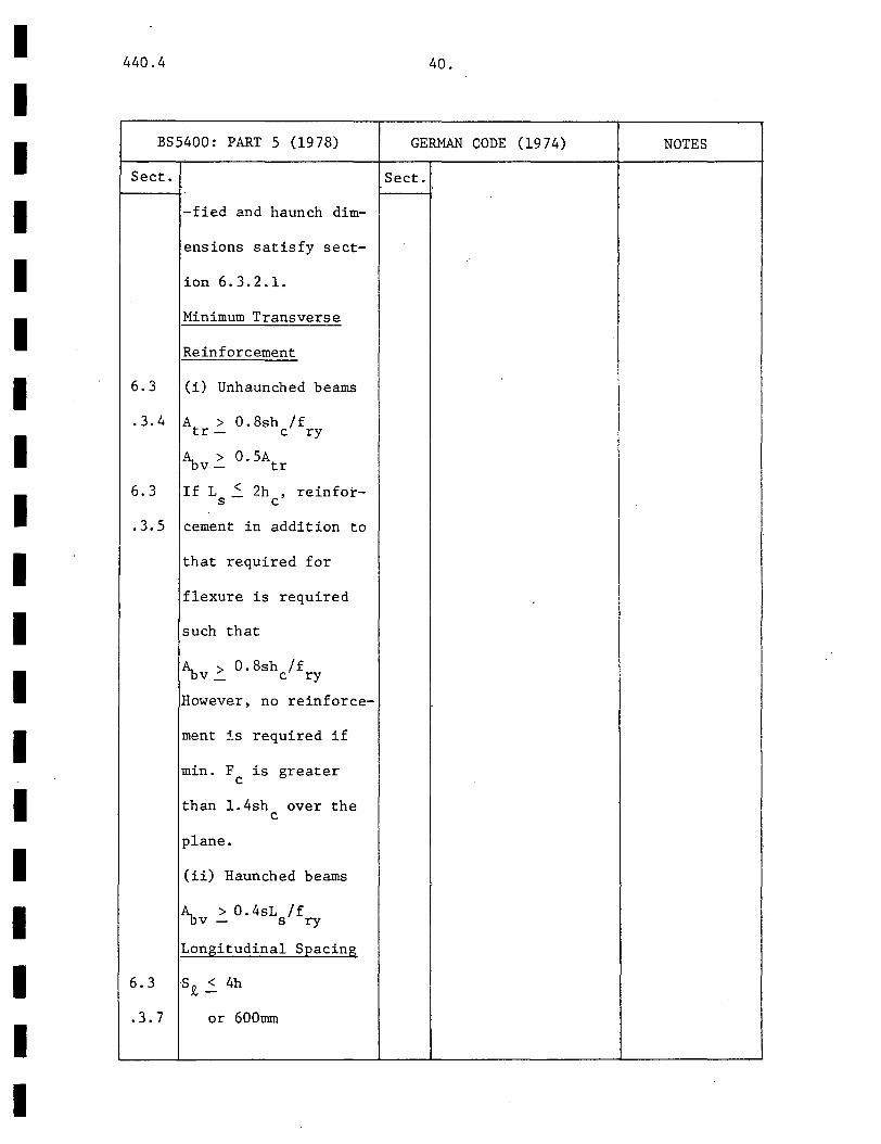
BS5400: PART 5 (1978)
Sect.
-fied and haunch dim-
ensions satisfy sect-
ion 6.3.2.1.
Minimum Transverse
Reinforcement
6.3 (i) Unhaunched beams
.3.4 A > 0.8sh /f tr- c ry
A > 0.5A -DV- tr
6.3 If L ~ 2h , reinfot-s c
.3.5 cement in addition to
that required for
flexure is required
such that
A > 0. 8sh /f -ov _ c ry
However, no reinforce-
ment is required if
min. F is greater c
than 1.4sh over the c
plane.
(ii) Haunched beams
A > 0.4sL /f -DV - s ry
Longitudinal Spacing
6. 3 SJ!. ~ 4h
.3.7 or 600mm
40.
GERMAN CODE (1974) NOTES
Sect.
440.4 41.
TOPIC MONOGRAPH
Art.
End Regions
Of Beams
I
I I I
I
Haunches 9.2-2 Haunch dimensions need
to be carefully chosen
I
AISC SPECIFICATION (1978)
Sect.
I I I I I I I I I I I I I I I I I I I
I 440.4
I I
BS5400: PART 5 (1978)
Sect. Sect.
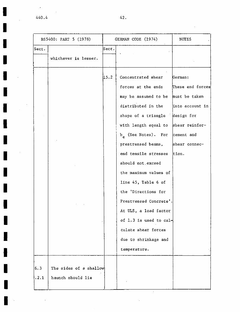
I whichever is lesser.
I 15.2
I I I I I I I I I I I I 6.3 The sides of a shallow
.2.1 haunch should lie
I I
42.
GERMAN CODE (1974) NOTES
Concentrated shear perman:
forces at the ends ~hese end forces
may be assumed to be ~ust be taken
distributed in the into account in
shape of a triangle design for
with length equal to shear reinfor-
b (See Notes). For cement and e
prestressed beams, shear connec-
end tensile stresses tion.
should not.exceed
the maximum values of
line 45, Table 6 of
the 'Directions for
Prestressed Concrete'.
At ULS, a load factor
of 1.3 is used to cal-
culate shear forces
due to shrinkage and
temperature.
440.4
TOPIC
Temperature
1 Effects
43 •.
MONOGRAPH AISC SPECIFICATION (1978)
Art.
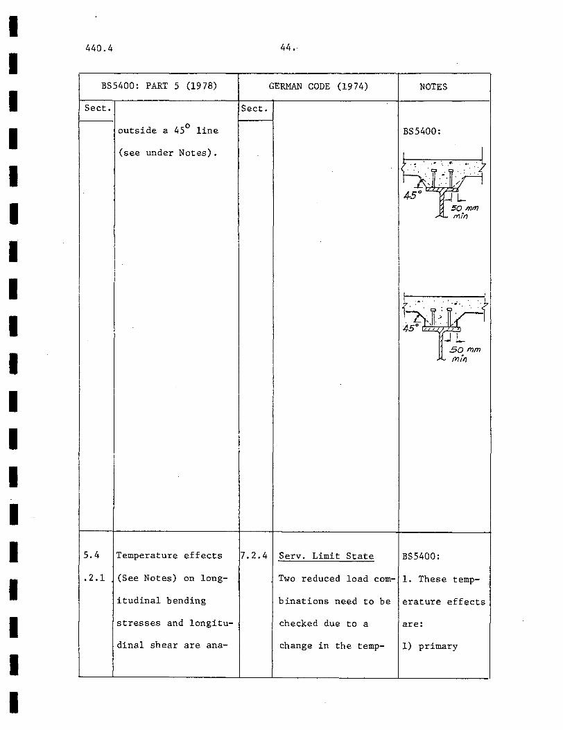
because the strength
of connectors depends
partly on the concrete
containment. A haunch
reduces the amount of
containment. Johnson
(19 71) (see Notes)
has proposed rules
which have been adop
ted in BS5400. Haun
ches can be divided
into shallow and deep
haunches. Deep haun-
ches require more care
in design and it is
recommended that each
deep haunch design be
verified by tests.
Sect.
9. 2-2 Changes in temperature . I jaffect longitudinal
~ending stresses, long- 7.12
itudinal shear flow
and deflections.
ACI CODE (19 77)
Clause 7.12 of the
ACI Building Code
requires temperature
and shrinkage reinfor-
I I I I I I I I I I I I I I I I ·I
I I
I I I I I I I I I I I I I I I I I I I
440.4
BS5400: PART 5 (1978)
Sect. Sect.
outside a 45° line
(see under Notes).
5.4 Temperature effects 7.2.4
.2.1 (See Notes) on long-
itudinal bending
stresses and longitu-
dina! shear are ana-
44.
GERMAN CODE (1974)
Serv. Limit State
NOTES
BS5400:
I
l~i·i· 4-5 0 'L-'-', :r!.....
50 mm -" '-' mlrJ
SO mm
BS5400:
Two reduced load com- 1. These temp-
I
binations need to be erature effects
checked due to a are:
change in the temp- 1) primary
440.4
TOPIC
Art.
45.
MONOGRAPH
Menzies (1968) has
found that temperature
effects can be large
enough to obscure the
effects of creep and
shrinkage on deflec-
tions.
Sect.
7.12
.2
ACI CODE (19 77)
cement for one-way
slabs.
The required percent-
ages are as follows
but not less than
0.0014.0.2% for slabs
with grade 40 or 50
deformed bars, 0.18%
for slabs with grade
60 deformed bars or
welded wire fabric
and 60000 (0.18/f ) y
for slabs with rein-
forcement of yield
greater than 60000 psi
at 0.35% strain.
I I I I I I I I I I I I I I I I I I I

I I I I I I I I I
I I I I I I I I I
440.4
BS5400: PART 5 (1978)
Sect.
5.4
-lysed by elastic
theory assuming full
interaction. The mod-
ular ratio a. is that e
for short-term loading
Appropriate effective
widths are to be used
as shown below. The
. 2.2 coefficient of linear
expansion for steel
and normal density
concrete is taken as
12 x 10-6 per °C and
8 x 10⁻⁶ per °C for
lightweight concrete.
This method applies
for both SLS and ULS
with appropriate fac-
tors for each state.
5.4 Longitudinal Shear
.2.1 The shear force due to
primary temperature
effects Q at SLS can
be assumed to be fully
Sect.
46.
GERMAN CODE (1974) NOTES
-erature: effects due to
1) Full dead and live uniform change
load with half the in temperature
temperature differ- with different
ence. rates of ex-
2) Full dead load and pansion for
temperature differ-
ence and half the
live load .
The coefficient of
linear expansion a t
may be taken as 1.2
x 10-5 per °C for
steel and concrete.
concrete and
steel.
2) primary
effects due to
a temperature
gradient across
the depth of
the section.
3) in cont-
inuous members,
secondary
effects due to
redistribution
of moments and
support reac-
tions caused
by 1 and 2.
440.4 47.
TOPIC MONOGRAPH
Art . .
..
ACI CODE
Sect. ..
I
I
I
(1977)
I I
I I I I I I I I I I I I I I I I I I I

I I I I I I I I I I I I I I I I I I I
440.4
BS5400: PART 5 (1978)
Sect.
transmitted by connec-
tors at each end of
5.4 the beam. See Notes
.2.3 for assumed distri-
bution. At ULS, Q
6.1.5 need to/need not be
considered for trans-
verse reinforcement/
connector design.
Longitudinal Bending
5.4 Stresses
.2.1 Effective widths are
determined from sec-
tion 5.2.3.
5.4 At SLS, the assump-
.2.4 tions of section
5.4.2.1 apply.
6.1.5 Ultimate Limit State
Needs to be considered
for slender sections
only (see section
6.2.2.2). Section
5.4.2 applies.
48 ..
GERMAN CODE (1974) NOTES
2. Distribution
of Q:
where K is
0.003/0.0015
for stud/other
connectors in
normal concrete
and similarily
0.006/0.003 in
lightweight
concrete.
3. Effective
widths are
obtained from
section 5.3.1
assuming un-
cracked con-
crete.
440.4 49.
TOPIC MONOGRAPH
Art.
Shrinkage 9.2-2 Shrinkage and creep,
and Creep besides producing add-
Effects itional long-term de-
flections, also affects
the stress distributior
in the same way as
temperature.
I
~ect.
7.12
ACI CODE (19 77)
Clause 7.12 of the
.ACI Building Code
is applicable.
I I I I I I I I I I I I I I I I I I I

I I I I I I I I I ·I
I I I I I I I I I
440.4
BS5400: PART 5 (1978)
Sect.
5.4.3 Serv. Limit State
The method of section
5.4.2 applies except
that values for the
free shrinkage strain
E and the long-term s
modular ratio a are e
used where
= E /(rJ E). s c c
E is -100/-200/-300 s
x 10-6 for very humid/
open air/very dry con-
ditions. 0c is sim-
ilarly 0.5/0.4/0.3.
6.1.5 Ultimate Limit State
Longitudinal bending
stresses are calcul-
ated for slender sec-
tions 5.4.2 and 5.4.3.
Longitudinal shear
need to/need not be
considered in trans-
verse reinforcement/
connector design.
50.
GERMAN CODE (1974) NarES
Sect.
5.5.7 Clause 8.7 of the BS5400:
'Directions for Pre- The values of
stressed Concrete'
applies.
I
I
E and 0c s
(Table 9)
apply only if
the concrete
specified
complies with
the following
figure:
Cetn~llf, hj/mg .5()Cl
1/'/0 4C()
% wjc (/; rafio
. 4-5 .:s . (.5
If not,E and s
the creep co-
efficient 0
are determined
from Part 4,
whence
0 = 1/(1 + 0) c
I

440.4
TOPIC
Deflection
51.
MONOGRAPH
Art.
ACI CODE (1977)/ AISC SPECIFtCATION (1978)
Sect.
9.2-2 Short-term deflections AISC For partial composite
can generally be cal- 1.11 action, the effective
culated from an elas- .4 moment of inertia for
tic analysis of the deflection computations
transformed section is
assuming full inter- = I + (I - I ) s tr s
action. In practice, /Vh lJvh
slip adds about 15% (1.11-6)
extra to the computed AISC The modular ratio n
value. 1.11 shall be that value
Shrinkage and creep :2 appropriate to the
Many tests (McGarraugh strength and weight
and Baldwin 1971; concrete specified.
Janss, 1972) have
shown that creep and ~CI Shrinkage, creep
shrinkage produce sig- 9.5 Additional long-term
nificant long-term .2.5 deflections for both
deflections. Creep normal and lightweight
strain is accounted for concrete may be ob-
by using a reduced tained by multiplying
modulus of elasticity the short-term de-
for concrete. Shrink- flection by
age strains are more (2- 1.2 (A 1 /A ))> 0.6 s s -
I I I I I· I I I I I I I I I I I I I I

I I I I I I I I I I I I I I I I
I
440.4
BS5400: PART 5 (1978)
Sect.
5.5 No limiting values
are given. Elastic
theory may be used
provided the limits
of section 4.3.2 are
not exceeded.
5.5.2 The values of the
partial safety factors
for loads are all
unity.
Effective Width
The effective width
ratio ~ is assumed
constant for all
loadings along an
equivalent simply
supported beam, and
is equal to the 1/4
span value from
Table 2 for UDL. For
cantilevers, ~ is the
value at the support
from Table 3 for UDL.
52.
GERMAN CODE (1974) NOTES
~ect.
14 No limits are given. BS5400:
Concrete in tension The effective
is taken into account widths have
Creep and shrinkage been assumed
effects must also be constant for
included. the calcula-
tions to be
practical.

440.4
TOPIC
Art.
CalculatioiJ
Of Loads
53 ..
MONOGRAPH ACI CODE (1977) / AISC SPECIFICATION (1978)
Sect.
nearly constant and ~CI Table 9.5 (b) gives
Ciolina (1971) has re- 9.5 limiting deflections.
ported a value of 3.1 .5.3 For floors and flat
-'+ x 10 for the shrink- roofs not attached to
age coefficient. non-structural ele-
Shrinkage is accounted ments likely to be
for by applying an damaged by large de-
equivalent compressive flections, the limits
force corresponding to are £/360 and £/180
unrestrained shrinkage respectively.
at mid-depth of the slab.
McGarraugh and Baldwin
have suggested that time-.
dependent deflections be
taken as equal to short-
term deflection. Johnson
(1975) has propo~ed some
limiting span depth ratios.
I I I I I I I I I I I I I I I I I I I

I I I I I I I I I I I I I I I I I I I
440.4
BS5400: PART 5 (1978)
Sect.
Shrinkage, Creep
Need to be considered,
E 1 may be determined c
from section 4.2.3 or
alternatively as
E /(1 + 0). Full c
interaction is assum-
ed and concrete in
tension is neglected.
5.1.1 Serv. Limit State
An elastic analysis
is used assuming un-
cracked concrete.
However if at an in-
ternal support due to
maximum hogging
moments, f > O.lf , tc cu
54.
GERMAN CODE (1974)
Sect.
NOTES
BS5400:
1. The condi-
tions for
plastic analy-
sis are:
1) compact
section I
2) equilibrium

440.4 55.
TOPIC MONOGRAPH
Art.
I
AISC SPECIFICATION (1978) -··-
Sect.
I
I
1
' ! I
I
I I I I I I I I I I I I I I I I I I I
I I I I I I I I I I I I I I I I I I I
440.4 56.
BS5400: PART 5 (1978) GERMAN CODE (1974)
Sect. Sect. 1------1.
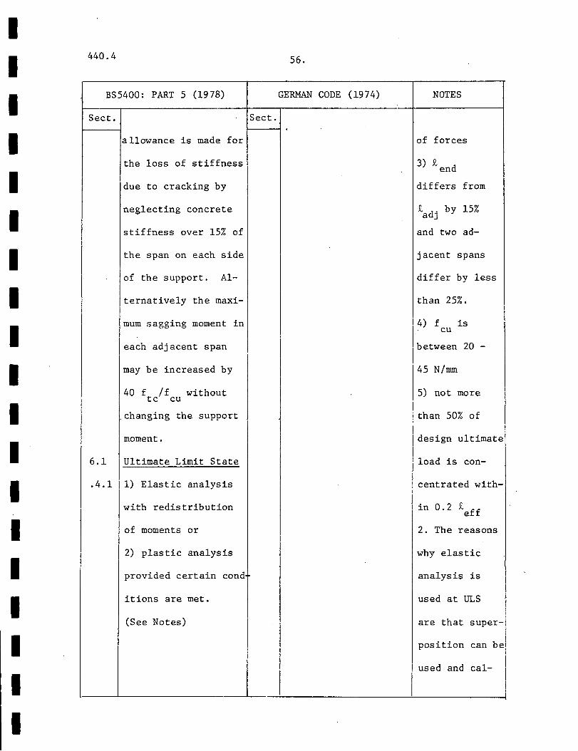
allowance is made for
the loss of stiffness
due to cracking by
neglecting concrete
stiffness over 15% of
the span on each side
of the support. Al-
ternatively the maxi-
mum sagging moment in
each adjacent span
may be increased by
NOTES
of forces
3) £ d en
differs from
n b 15% -"adj Y
and two ad-
j acent spans
differ by less
than 25%.
I 4) f is cu
between 20 -
45 N/mm
40 f /f without tc cu j
.changing the support
5) not more
I ! than 50% of I
moment. design ultimate
6.1 Ultimate Limit State load is con-
.4.1 1) Elastic analysis centrated with-
with redistribution
of moments or 2. The reasons
2) plastic analysis why elastic
provided certain cond analysis is
itions are met. used at ULS
(See Notes) are that super-
I position can be,
I used and cal-
l--'-----_L--'--------'---------l

I 440.4 57.
I TOPIC MONOGRAPH AISC SPECIFICATION (1978)
I Art. Sect.
1.5 Redistribution of I .1.4 Moments
For moments caused I by gravity loads only.
For compact sections, I 10% reduction of sup- I port moments with
corresponding increase I of 10% of average neg-
ative moments in the I value of the maximum I positive moment.
I I I I I I I I I
I I I I I I I II II I I I I I I I I I I
440.4
BS5400: PART 5 (1978)
Sect.
6.1
.4.2
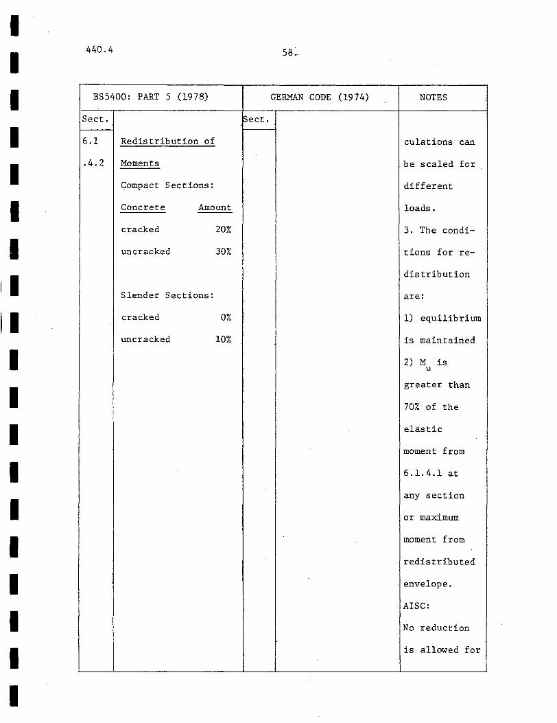
Redistribution of
Moments
Compact Sections:·
Concrete
cracked
Amount
uncracked
Slender Sections:
cracked
uncracked
20%
30%
0%
10%
ss:.
GERMAN CODE (1974)
lsect.
NOTES
culations can
be scaled for
different
loads.
3. The condi-
tions for re
distribution
are:
1) equilibrium
is maintained
2) M is u
greater than
70% of the
elastic
moment from
6 .1. 4.1 at
any section
or maximum
moment from
redistributed
envelope.
AISC:
No reduction
is allowed for
440.4 59.
TOPIC MONOGRAPH
Art.
Compact
And Slender
Sections
AISC SPECIFICATION (1978)
Sect.
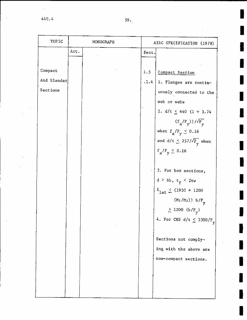
1.5 Compact Section
.1.4 1. Flanges are contin-
uously connected to the
web or webs
2. d/t 2 640 (1 + 3.74
(f /F ))//F a y y
when f /F < 0.16 a y-
and d/t < 257//F when -- y
f /F < 0.16 a y-
3. For box sections,
d > 6b, tf < 2tw
£lat ~ (1950 + 1200
(MIIM2) ) b /F y
> 1200 (b/F ) y
4. For CHS d/t < 3300/F - y
Sections not comply-
ing with the above are
non-compact sections.
I I I I I I I I I I I I I I I I I I I
I I I I I I I I I I I I I I I I I I I
440.4
BS5400: PART 5 (1978)
Sect.
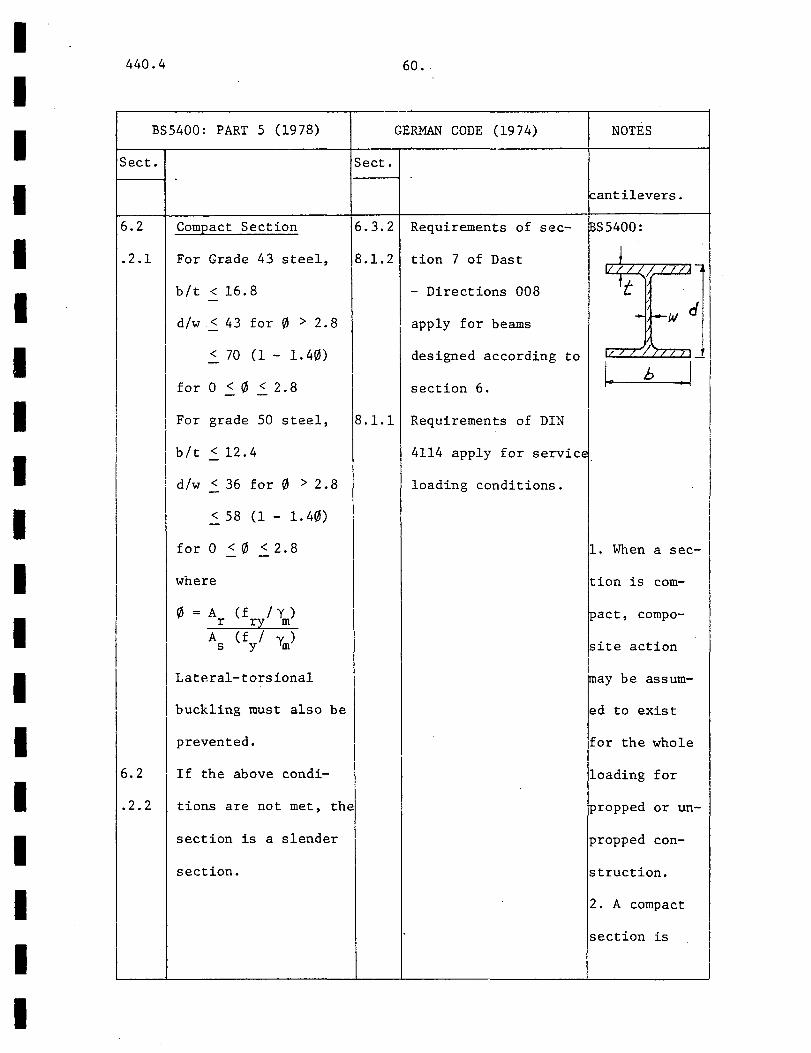
6.2
.2.1
6.2
.2.2
Compact Section
For Grade 43 steel,
b/t < 16.8
dlw ~ 43 for 0 > 2.8
< 70 (1- 1.40)
for 0 ~ 0 < 2.8
I For grade 50 steel,
bit <12.4
dlw < 36 for 0 > 2. 8
<58 (1- 1.40)
for0~0~2.8
\vhere
0 = A r A
s
(f I y) ry m (f I Y. ) y m
Lateral-torsional
buckling must also be
prevented.
If the above condi-
tions are not met, the
section is a slender
section.
60.
GERMAN CODE (1974) NOTES
Sect.
Fantilevers.
6.3.2 Requirements of sec- ~S5400:
8.1.2
8.1.1
tion 7 of Dast
- Directions 008
apply for beams
designed according to
section 6.
Requirements of DIN
IL.fL-< _L__lij -
t - 1--W cf
4114 apply for service.
loading conditions.
1. When a sec-
tion is com-
tpact, compo-
site action
!may be assum-
ed to exist
lfor the whole
loading for
propped or un-
propped con-
struction.
2. A compact
section is
440.4
TOPIC
Art.
I I
I ! I I I I
I I
I I
I I I
I I
I i I
I
61.
MONOGRAPH
I
AISC SPECIFICATION (1978)
Sect.
I
I I I
I
I I I I I I I I I I I I I I I I I I I
I I I I I I I I I I I I I I I I I
440.4
BS5400:
~ect.
i
; I
I I
I
62.
PART 5 (19 78) GERMAN CODE (1974)
Sect.
NOTES
defined so
that plastic
theory may be
applied.
AISC:
Three cate-
gories of
profiles are
recognised in
the AISC spec-
ification:
(i) non-compact
sections
(ii) compact
sections
(iii) plastic
design sections
The compact
section of
BS5400
corresponds to
category (iii).

440.4
' TOPIC
Art.
Strength
Of Sections,
Ultimate
Moment
I I
I I
I
I
I
I I I
I I
I I
63."
MONOGRAPH AISC SPECIFICATION (1978)
Sect.
I
I . I
I !
I
I
I I I
I
I I i i
I I
1 I I
I
I
I I I I I I I I I I I I I I I I I I I

I I I I I I I I I I I I I I I I I I I
440.4 64.
BS5400: PART 5 (1978) GERMAN CODE (1974) NOTES
Sect.
6.2
.3.1
6.2
.4.1
Sect.
Compact Section
Plastic theory with a 6.3.2
rectangular stress
block (See Notes) is
applicable.
Slender Section
Use elastic theory
with effective widths
from section 5.2.3.
Temperature and
shrinkage effects must
be included. Alter-
natively, if the
neutral axis is withi~
the concrete, section
6.2.3.1 may be used.
~.3.3
Two methods are given
Strain Limitations
f = 0.6 8 c wn
E unlimited st
E is unlimited if sc
BS5400: p 0-4-TciJ J.-.-:-1
~
I compactness require- !5/tml I 1 ments of Dast - Dir- For slender I
ections 008 are sat- sections, it
isfied. is found that
E. < 0.0005 if temperature ct-
E < - 0.0035, and shrinkage cc-
or where a compress- effects are j
ive force with a ·,
small eccentricity
is present.
E = -0.0035 -cc
0. 75E a
Plastic Theory
included in an
elastic
!analysis at
ULS, no check
for flexural
I 1 A rectangular stress
stresses need
Ito be made at i I block is assumed. SLS.
The neutral axis must German:
not lie in the web. 1. Only the
For non-prestressed flanges are
·composite beams: assumed to
440.4 65.
TOPIC MONOGRAPH AISC
Art. Sect.
Vertical
Shear 1.11 . 3
I
._______
SPECIFICATION (1978)
End Shear
The web and end conn-
ection of the steel
shall be designed to
carry the total reac-
tion. If it is not
given, it may be cal-
culated as
0.33S Fb/L R = tr
for uniformly load
simple span beams.
'
I
I i I I I !
I I I I I I I I I I I I I I I I I I I
I I I I I I I I I I I I I I I I I I I
I I
I
I I
I
440.4
BS5400: PART 5 ( 19 7 8)
Sect. Sect.
6.4.2
6.4.3
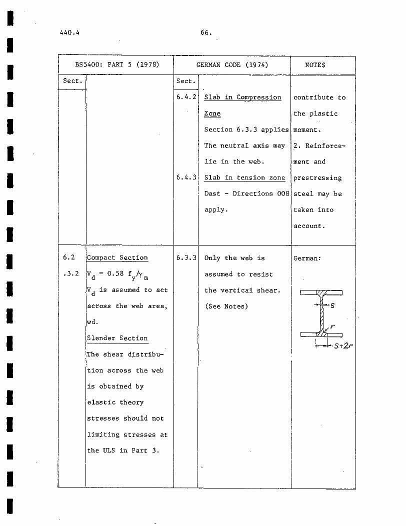
6.2 Compact Section 6.3.3
.3.2 v d = 0. 58 f /y Y m
Vd is assumed to act
across the web area,
wd.
Slender Section
The shear distribu-
tion across the web
is obtained by
elastic theory
stresses should not
limiting stresses at
the ULS in Part 3.
66.
GERMAN CODE (19 74) NOTES ~ -
Slab in Compression contribute to
Zone the plastic --Section 6.3.3 applies moment.
The neutral axis may 2. Reinforce-
lie in the web. ment and
Slab in tension zone prestressing I I Dast - Directions 008 steel may be I
I I
apply. taken into
account. I I I
Only the web is German:
assumed to resist
I the vertical shear. I/ '.t:l J
(See Notes) - 1--S
1 vr ~S-t2r
;
I
i

I 440.4 67.
I TOPIC MONOGRAPH AISC SPECIFICATION (1978)
Art. Sect. I Influence of I Vertical
Shear on I Ultimate
Moment I I I
I
I
I I I
I I
Encased 19.4-2. Encasement increases ~.ll,l No restrictions on the
Beams, I the stiffness and grade of concrete. I
i I
I I
I
General energy absorption and
reduces the possibili- Allowable stresses I
lsee section 1.11.2.1 ty of lateral-torsion-
al buckling and local
I I
buckling. Usually I full encasement is I necessary for reliable• I composite action.
I I
I I I
I I
I 1 ' I I

I I I I I I I I I I I I I
II I I I I
440.4
BS5400: PART 5 (1978)
Sect. ~ect.
6.2 No reduction in M 16.3.1 u
.3.3 need to be considered
if
1) V < 0. 3V d
2) in negative moment 5.3.3
I regions, the force ' I I ratio ~ (see section I
I 6.2.2.1) is greater
than 0.15 provided i I
v < vd.
I
I 8.1 Encasement must be i
. 8. 3 normal density con-
crete of minimum I I
density 2300 kg/m 3•
I i
The distribution of ! I
l moments and shear at I I SLS and ULS is deter-
mined by elastic
analysis (sections
5.1, 6 .1). No redis-
tribution of moments i1
I permitted.
[ In general, the
68.
GERMAN CODE (1974) NOTES
Need not be considered German:
if Q /Q 1 < 0.3 . v p - M/ll!pt
where /.0
Qpl = A aF/13 ~ I w
If Q > 0.3Q l' M is v p u a.3 /0
reduced by the use of Qv/O,i
a reduction diagram where
(see Notes). M = M i i f flange I
I I
-There are -no provi.,.. I
sions for encased I I
beams in this code. j I
I I

440.4 69.
TOPIC MONOGRAPH
Art.
Encased
Beams,
Longitudinal
Bending
Stresses
Encased
I 9.4- Two approaches to bond
Beams, I 3 failure criteria have
Longitudinal been proposed:
Shear Elastic Approach
(Caughey, 1936; Wong,
1963)
The rate of change of
:net axial force in
the steel section
divided by the peri-
AISC SPECIFICATION (1978)
Sect.
:
I I I I I I I I I I I I I I I I I I I

I I I I I I I I I I I I I I I I I
II
I
440.4
BS5400: PART 5 (1978)
Sect.
requirements of
sections 4, 5 and 6
are to be satisfied.
8.4.1 Serv. Limit State
These are determined
by an elastic analysis
according to section
5.2.
Ultimate Limit State
An elastic analysis
according to section
6.2.4.1 is used.
8.5.1 Serv. Limit State
Shear flow is calcu-
lated by elastic
I theory according to
section 5.3.1. In
positive moment
regions, concrete in
tension is neglected.
fbs 2_ 0. 5 N /nnn2
If fbs > 0.5 N/nnn2
70.
GERMAN CODE (1974) NOTES
Sect.
BS5400:
1. fbs does not
include contri-
bution from
temperature
and shrinkage
which are con-
sidered sepa-
rately.
440.4 71.
TOPIC MONOGRAPH
Art.
meter is limited to
.07 N/mm2 •
Inelastic Approach
... (Hawkins, 1974)
The average anchorage
bond stress over the
perimeter between zero
and maximum moment
positions is limited tc
the maximum bond stress
. from pushout tests.
I
AISC SPECIFICATION (1978)
Sect.
I
I I I
I
I I I I I I I I I I I I I I I I I I I
I I I I I I I I I I I I I I I I I I I
440.4
BS5400: PART 5 (1978)
Sect.
ignore bond and pro-
vide shear connection.
8.5.2 Ultimate Limit State
Section 8.5.1 is app-
licable but with de-
sign loading at ULS.
I Bond stress need not
be checked.
I A > (q - k 1 sL )/ e_ p s
(0.7f ) ry
(see App. 4, Fig. 6d)
S.8 or
A > 0.8sL /f e- s ry
(2)
whichever is bigger.
I I I
72.
GERMAN CODE (1974) NOTES
Sect.
loads, bond
is almost al-
ways broken
due to
cracking and
I land local bond !
i failure. Hen-I I ce no check is
placed on fbs
I at ULS. i
3. Equation
(2) gives min-
imum stirrup
~
!requirements.
MONOGRAPH:
Pushout tests
show that
maximum bond
stress is sen-
sitive to con-
crete cover,
amount of hoop
reinforcement
and others.

440.4 73.
TOPIC MONOGRAPH AISC
Art. Sect.
Encased
Beams,
Temperature .
And
Shrinkage
I Effects
Encased 1.11
Beams .1
I Cracking
I
' ' I
I
-
SPECIFICATION (1978)
Mesh or other rein-
forcing steel through-
out the whole depth
and across the soffit
of the beam must be
provided to prevent
spalling of concrete.
I I I I I I I I I I I I I I I I I I I
I I I I I I I I I I I I I 1-I I I I I
440.4
BS5400: PART 5 (1978)
Sect.
8.6.1 Considered at the
serv. limit state
8.6.2 Longitudinal Bending
18.6. 3 Stress and Shear
I Sections 5. 4. 2 and
I
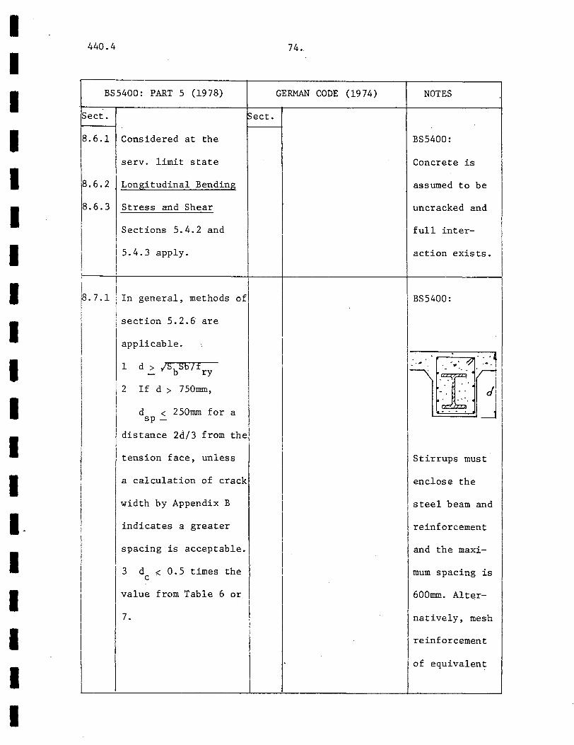
I i F.7.1 In general, methods of
15.4.3 apply.
I section 5.2.6 are
applicable.
1 d > ISbSb/f - ry
If d > 750mm,
d < 250mm for a sp-
distance 2d/3 from the
tension face, unless
a calculation of crack
width by Appendix B
indicates a greater
spacing is acceptable.
3 d < 0.5 times the c
value from Table 6 or
7.
74.
GERMAN CODE (1974) NOTES
::>ect.
BS5400:
Concrete is
assumed to be
uncracked and
full inter-
action exists.
BS5400:
: . .-·.·[]: .. ·:.J ~~ ~r· .•.·· ·nj
• .. . I I
Stirrups must
enclose the
steel beam and
reinforcement
and the maxi-
mum spacing is
600mm. Alter-
natively, mesh
reinforcement
of equivalent
I 440.4 75.
I TOPIC MONOGRAPH AISC SPECIFICATION (19 78)
I Art. ~ect.
I I
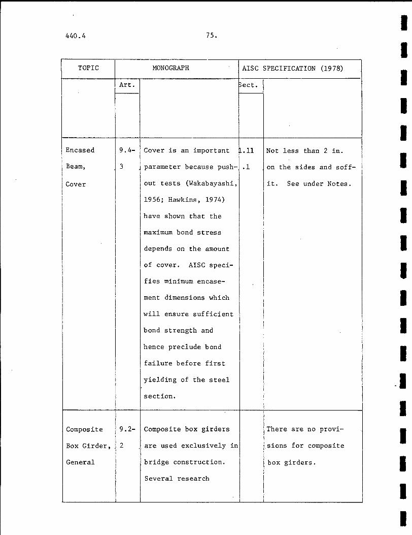
Encased 9. 4- Cover is an important .11 Not less than 2 in.
I I
I Beam, 3 parameter because push- .1 on the sides and soff-I I
I I Cover out tests (Wakabayashi, I it. See under Notes. i I
I
I I i 1956; Hawkins, 1974) I i '
I have shown that the I I I I
I I maximum bond stress I
I I I
I I depends I
i on the amount I I
I I of cover. AISC speci-
I I I
fies minimum encase- I I ! I I ment dimensions which I
i
I I
will ensure sufficient i I I bond strength and
hence preclude bond I I i failure before first I
I I
yielding of the steel -1 I
section.
I I Composite 9.2- Composite box girders There are no provi-
I j Box Girder, 2 are used exclusively in J.sions for composite I
I I I
General bridge construction. box girders. I Several research
I I

I 440.4 76.
I I
BS5400: PART 5 (19 78) GERMAN CODE (1974) NOTES
Sect. Sect.
I area may be
used.
I I
8.8 Not less than 50mm AISC:
anywhere.
I , "
I lz ~--.
'
I I ···m. ~·I I
I I I
I I I
' I
I I
I I
I I I
I I I
I I I 7.1 In general, composite There are no provi-
box girders should sions for composite
I satisfy BS5400: Part box girders. I I
I 3, the requirements I I I I I -
I
440.4
TOPIC
Art.
I Composite I
Box Girder,
Shear
Connector
I Design
77.
MONOGRAPH
several research in-
vestigations have beer.
done (Kavanagh, 1967;
Galambos et al.' 196 7;
Mattock and Johnston,
1967, 1968).
AISC SPECIFICATION (1978)
Sect.
I I I I I I I I I I I I I I I I I I I

I I I I I I I I I I I I I I I I I I I
I
I
440.4
BS5400: PART 5 (19 78)
Sect. Sect.
for uncased beams and.
the additional re-
quirements of this
section.
7.3 Effective Width
In accordance with
sections 5 or 6.
7.4 Distribution of
Forces
In accordance with
sections 5 .1. 1 or 6 . 1.
7.5.2 Design at SLS
Closed Box Girder
Sections 5.3.3.5 and
5.3.3.6 are to be
satisfied as follows:
Q = .9.. [k(l - ~)2 + X
b n
0.15]
and not less than
design strength 0.55P u
from section 5 where k
and b are as shown.
(See Notes.)
78 ..
GERMAN CODE (1974) NOTES
-
I
BS5400: I
bib r---+1 I
I rr 1 1r t ~ . ·.I. .. :. · .... · : ... ·I 11. ~ • :.
I
I I
I
I I
r-k-t i I r I
l-- ..... _ . .I .. . . . . · . I
I I
t£ I
I
440.4 79.
TOPIC MONOGRAPu
~rt.
I Composite I
Box Girder,
Connector
Spacing
I
Composite
Box Girder,
Torsion
Permanent 9. 7-2 The AISI method
Formwork, follows a load and re-
Structurally sistance factor format.
Participating Load factors are gen-
-AI5E
Sect.
1.11
.5
SPEe'IF'ICATIONS (1978)
Composite beams with
formed metal deck are
designed by the pro-
visions of section
I I I I I I I I I I I I I I I I I I I
I I I I I I I.
I I I I I I I I I I I I
440.4
BS5400: PART 5 (1978)
Sect.
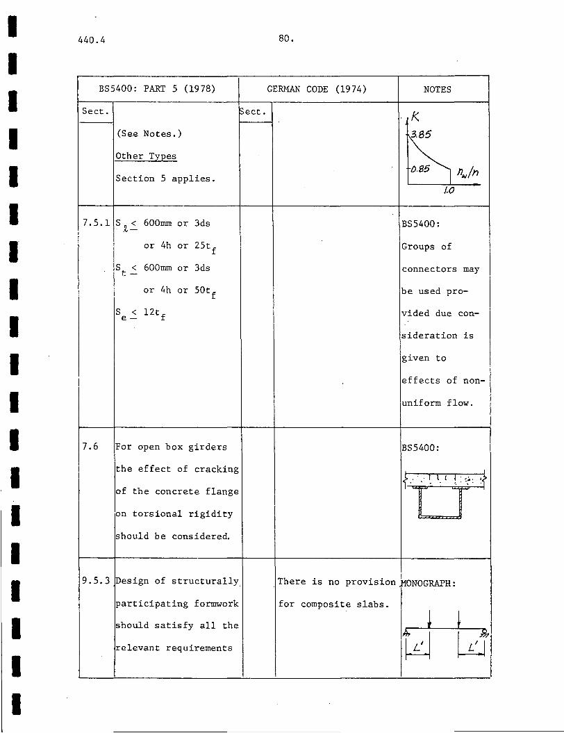
(See Notes.)
Other Types
Section 5 applies.
7.5.1 s .~2 600mm or 3ds
or 4h or 25tf
s < t-
600mm or 3ds
or 4h or 50tf
s < 12tf e-
7.6 For open box girders
the effect of cracking
of the concrete flange
on torsional rigidity
should be considere~
9.5.3 ~esign of structurally
participating formwork
should satisfy all the
relevant requirements
Sect.
80.
GERMAN CODE (1974) NOTES
1<.
BS5400:
Groups of
connectors may
be used pro-
vided due con-
sideration is
given to
effects of non-
uniform flow.
BS5400:
I
)-_.·:It_< ! :::.:· !.> 1- .. . .. ;i
.There is no provision ~ONOGRAPH:
for composite slabs.

TOPIC
Art.
81.
MONOGRAPH
erally the same as
those in the ACI Code.
Shear Bond Failure
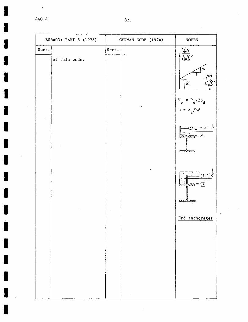
v u
= 0 [12d (Mpd S 1 1
+ k/r::) + c
I 0.5 w1L] lb/ft.
I (9.47)
for simply supported
spans. Equations for
under and over-rein-
j forced flexural failure
are also given. k and
m are obtained from a
diagram (see Notes).
European Criteria
Swiss research has
shown that composite
action can be achieved
through bond, and com-
posite floors with
trapezoidal deck can be
treated as homogenous
R.C. section. The
allowable stresses are
AISC SPECIFICATION (1978)
Sect.
1.11.1 to 1.11.4 with
modifications as
described below.
Limitations on
Dimensions
See under Notes.
I I I I I I I I I I I I I I I I I I I
I I I I I I I I I I I I I I I I I I I
440.4 82.
BS5400: PART 5 (1978) GERMAN CODE (1974)
Sect. Sect.
of this code.
I I
NOTES
v = p /2bd e e
p = A /bd s
I
End anchorages
I

440.4
TOPIC
Art.
Formed
Deck, Deck I Ribs Perpen-.
dicular to
Steel Beam j I
MONOGRAPH
Tensile:
1.4~ kg/cm2
W2B
Bond: 0.5 kg/cm2
where
83.
(9. 48)
If TH > 0.5 kg/cm2,
end anchorages must be
provided to prevent
slip (see Notes) and
I these are designed for '
(9. 49)
For concentrated or
line loads, the MONO-
GRAPH gives formulas
for effective widths,
!based on the work of
Steinhardt in Germany.
AISC SPECIFICATION (1978)
Sect.
1.11
.5.2
q = k x value from
Tables 1.11.4,
1.11.4A
where
w H k = ~(_E) (~ - 1)
'V'l" h h r r r < 1.0 (1.11-8)
I I I I I I I I I I I I I I I I I I I
I I I I I I I I I I I I I I I I I I I
440.4
BS5400:
Sect.
I
I
84.
PART 5 (19 78) GERMAN CODE (1974)
Sect.
I
NOTES
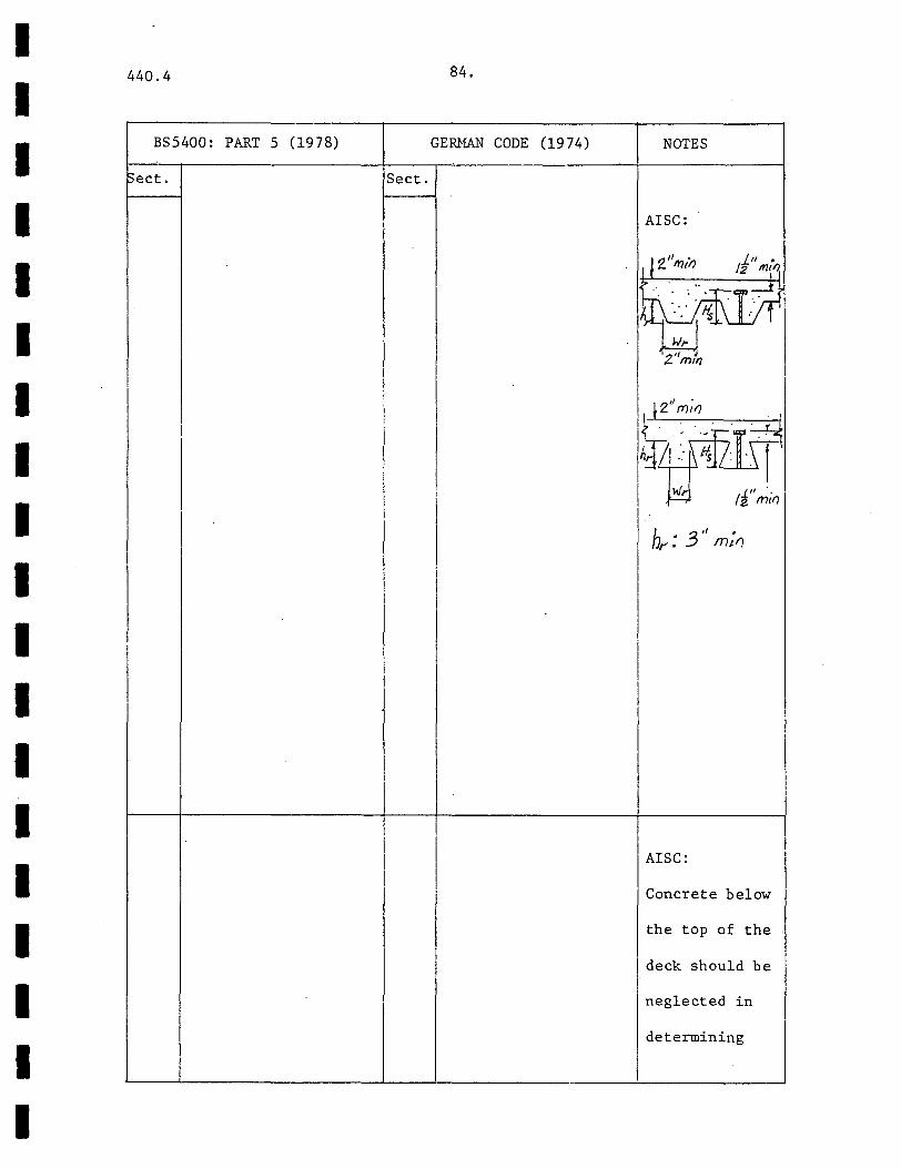
AISC:
iJ2''m,n }_II • /z "'~1
Itt~ .~·~ ... ·.·
. w~ J ~ 2 m1f/
t 2'' m;rJ {· ... ~ h~j21·~l\ ~ 11" . 2 mcfl
h 3'' . r: mtfJ
I
I
I
AISC:
Concrete below
the top of the
deck should be
neglected in
determining
440.4
TOPIC
I Formed
I Deck, Deck
[Ribs Parallel
Ito Steel I !Beam I I
I I
I I I 1
l I I
Composite
Column,
Materials
85.
MONOGRAPH AISC
~rt. Sect.
11.11
.5.3
I I
SPECIFICATION (1978)
I H < h + 3 I s r
N < 3, SL~ 32" r-
To resist uplift, I anchorage may be
I provided by connectors
or welds at a maximum
spacing of 16". I I
q = k x value from
I Tables 1.11. 4,
1.11. 4A I where I !
w H I I k = 0.6 (__£) (2- 1) h h
< 1.0 r (1 ~11-9) -
I Steel deck ribs may be
split and separated to
I form a haunch (see
under Notes). I ACI CODE (1977)
There is no provision I in the AISC Specifi-
I cation for composite
columns. These are I given in ACI318-77.
I I I
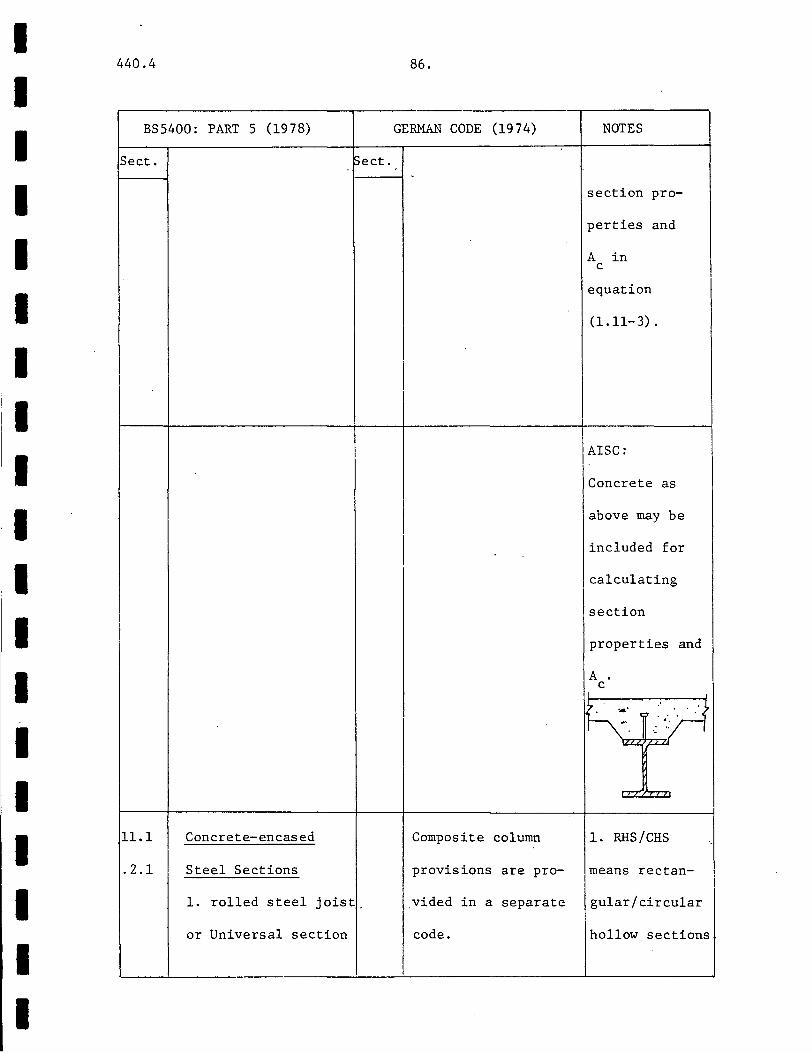
I I I I I I I I I I I I I I I I I I I
440.4
BS5400: PART 5 (1978)
Sect. Sect.
11.1 Concrete-encased
.2.1 Steel Sections
1. rolled steel joist_
or Universal section
86.
GERMAN CODE (1974)
Composite column
provisions are pro-
vided in a separate
code.
NOTES
section pro-
perties and
A in c
equation
(1.11-3).
AISC:
Concrete as
above may be
included for
calculating
section
properties and
A c
1. RHS/CHS
means rectan-
gular/circular
hollow sections
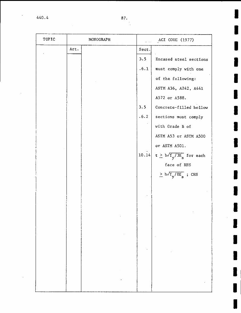
440.4 87.
r---·--
TOPIC MONOGRAPH --·- .
Art. Sect.
3.5
.6.1
3.5
. 6. 2
i -I 10.14
I
I
I
ACI com:: (1977) ·- -
Encased steel sections
must comply with one
of the following:
ASTM A36, A242, A441
AS 72 or A588.
Concrete-filled hollow
sections must comply
with Grade B of
ASTM A53 or ASTM A500
or ASTM A501.
t > blf /3E for each - y s
face of RHS
> hlf /BE - y s ; CHS
I I I I I I
I I I i I
I I I I I I I I I I I I I I I I I I I

I I I I I I I I I I I I I I I I I I I
440.4 88.
r---B-S_5_4_0_0_:_P __ AR_T __ 5 __ (_1_9_7_8_) ____ ~----G-E_RMAN ____ c_o_D_E __ (l_9_7_4_) _________ ;0-T_E_S ______ ~~
I
I
Sect. Sect.
11.1
of Grade 43, 50 steel
complying with BS4:
Part 1.
2. symmetrical I -
section fabricated
from Grade 43 or 50
I steel. I
I Concrete-filled
I I Hollow Sections
11. symmetrical box I !section from Grade 43
I
lor 50 steel or
.2. comply with BS4: I !Part 1 or BS4848:
IPart 2
13. t > bf/f /3E ; RHS
I
w- y s
> D/f /BE ; CHS - y s
!concrete
!Not less than 2300 kg/
m3. Tubes: f > cu
20N/mm2 • Encased:
f > 25N/mm cu
Aggregates < 20mm
ACI, BS5400:
2. Concrete-
filled hollow
sections must
have a wall
thickness I
!large enough
to attain the
l-ongitudinal
yield stress
before out-
ward buckling.
(Refs. 1, 2) I
I !
I I

440.4 89.
TOPIC MONOGRAPH AISC SPECIFICATION (1978)
Art. Sect.
Composite 9.5- Tests by Virdi and
Column, 2 Dowling (1975) on bond
Shear strength between cir-
Connection cular steel sections
and the concrete core
showed that bond conn-
ection was mainly
mechanical. Most of
the tests indicated
bond strengths in ex-
cess of 0.4 N/mm2•
Composite 9.4-3 The research of Basu ~0.14 Any axial load stren-
Column, and Somerville (1969) .3 gth assigned/not
Concrete has shown that the 0.14 assigned to the con-
Contribution shape of the inter- .. 4 crete of a composite
Factor action curve depends member shall be
on two critical fac-
tors:
1. slenderness ratio
2. a concrete contri-
bution factor a where
a = A a c u
Acr +Acr +Acr c u s y r s
(9. 25)
transferred to the
concrete/structural
steel shape, pipe or
tube by members or
brackets in direct
bearing on the con-
crete/direct bearing~
I I I I I I I I I I I I I I I I I I I
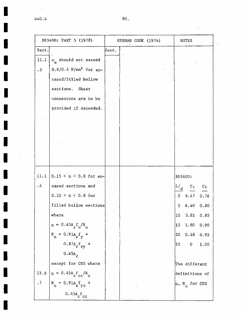
I I I I I I I I I I I I I I I I I I I
440.4
BS5400: PART 5 (1978)
Sect.
11.1 v should not exceed u
. 3 0.6/0.4 N/rnrn2 for en-
cased/filled hollow
sections. Shear
connectors are to be
provided if exceeded.
11.1 0.15 <a< 0.8 for en-
. 4 cased sections and
I 0.10 < a< 0.8 for
filled hollow sections
where
a = 0.45A f /N c u u
N = 0.91A f + u s y
0.87A f + rry
0.45A c
except for CHS where
ll.,S a = 0.45A f /N c cc u
. 7 N = 0.91A f + u s yc
0.45A f c cc
90.
GERMAN CODE (1974) NOTES
Sect.
BS5400:
L/d c1 c2 r-- - -
0 9.47 0.76
5 6.40 0.80
10 3.81 0.85
15 1. 80 0.90
20 0.48 0.95
25 0 1.00
rrhe different I I
I definitions of
a, N for CHS u

440.4 91.
~--~------~------------------------------,-·-----•------------------------.
TOPIC
I !Composite
Columns,
Homents and I
Forces
MONOGRAPH
Art.
ACI CODE (19 77)
Sect.
10.10 Ultimate
.1 An elastic analysis may
be used, taking proper
account of axial loads
and variable moments
of inertia on member
stiffness and fixed-
end moments, effects of
deflections and dura-
tions of loads.
10.10 Alternatively the
.2 approximate procedure
of section 10.11 may
be used:
10.11 Columns are designed
.5.1 for factored axial
load P and a magnified u .
I I I I I I I I I I I I I I I I I
I

I I I I I I I I I I I I I I I I I I I
440.4
BS5400: PART 5 (1978)
Sect.
f = f + c1 f (t/D) cc cu y
f = C2f yc y
(See Notes for C h C 2)
111.2 Ultimate Limit State !
.1 / 1. Loads and moments I
lma; be calculated by
an appropriate
elastic analysis
taking proper account
of the rotational and I
directional restraintj
of adjoining members
or
11.2
:~p::::::a::::0:emi- I
valid only if ad-
joining beams remain
elastic, otherwise
reduce their stiffness
11.2 The actual frame is
92.
GERMAN CODE (1974) NOTES
Sect.
take account
of the enhanc-
ed strength
due to triax-
ial contain-
ment.
BS5400:
w I IB I
I

440.4 93 •.
TOPIC MONOGRAPH ACI CODE (1977) ~--------~~---r---------------------4------·r----------------------4
Art. Sect.
10.14
.5
factored moment M c
where
(10-6)
where
6 = Omj ( 1 - P I C/JP ) u c
> 1.0 (10-7)
(10-8)
EI =(.2E I + E I )/ c g s t
(1 + (3d)
(10-13)
or conservatively,
EI = 0.2E I /(1 +(3d) c g
10.11 Value of C : m
.5.3 For braced members with
no transverse loads,
C = 0.6 + 0.4(Ml/M2) m
> 0.4
and C = 1 for others. m
10.11 For unbraced frames .
• 6 6 = C /(1 - EP /C/JEP ) m u c
where the summation is
for all columns in a
story.
I I I I I I I I I I I I I I I I I I I
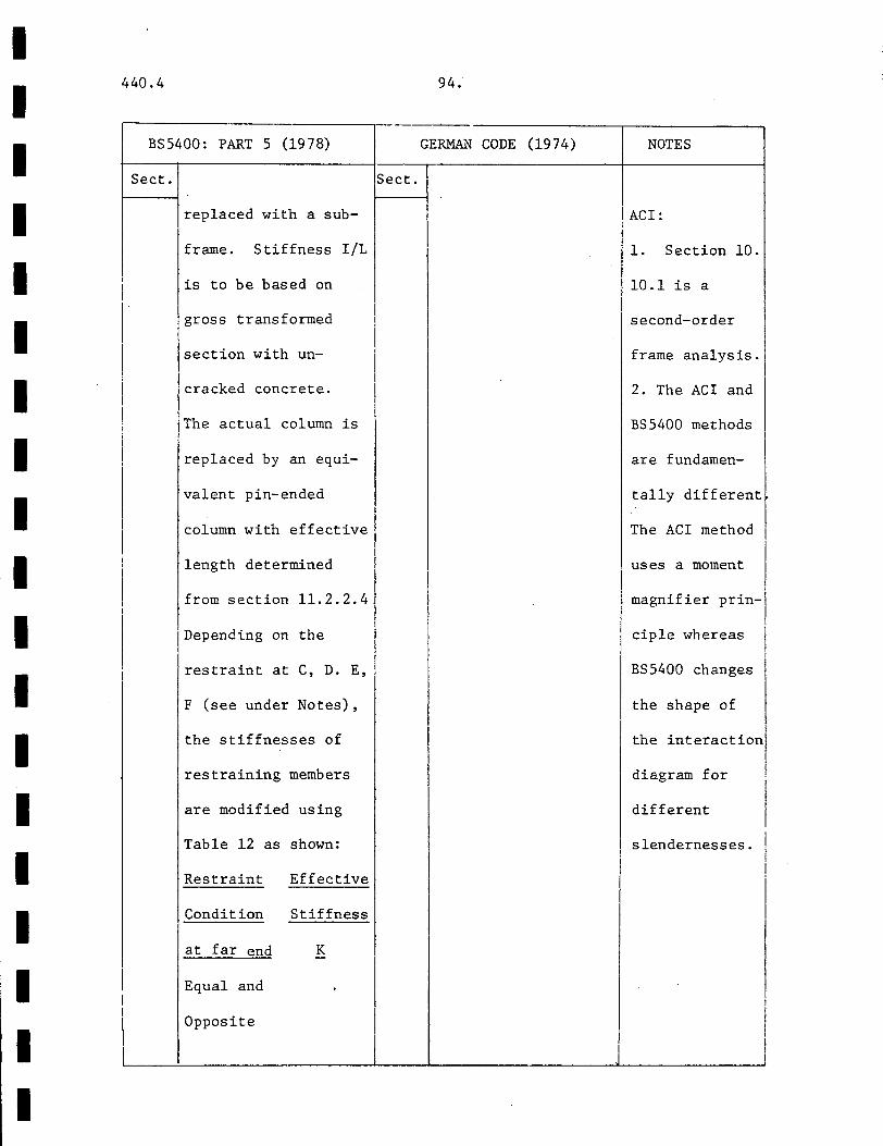
I I I I I I I I I I I I I I I I I I I
440.4
BS5400: PART 5 (1978)
I
I I I
I
Sect.
replaced with a sub-
frame. Stiffness I/L
is to be based on
gross transformed
section with un-
cracked concrete.
The actual column is
replaced by an equi-
valent pin-ended
column with effective
length determined
from section 11.2.2.4
Depending on the
restraint at C, D. E,
F (see under Notes),
the stiffnesses of
restraining members
are modified using
Table 12 as shown:
Restraint Effective
Condition Stiffness
at far end K
Equal and
Opposite
94.
GERMAN CODE (1974)
Sect.
NOTES
ACI:
1. Section 10.
10.1 is a
second-order
frame analysis.
2. The ACI and
BS5400 methods
are fundamen-
tally different
The ACI method
uses a moment
magnifier prin-1
ciple whereas I I
BS5400 changes
the shape of
the interaction!
diagram for I different I slendernesses. I
I
I
I J
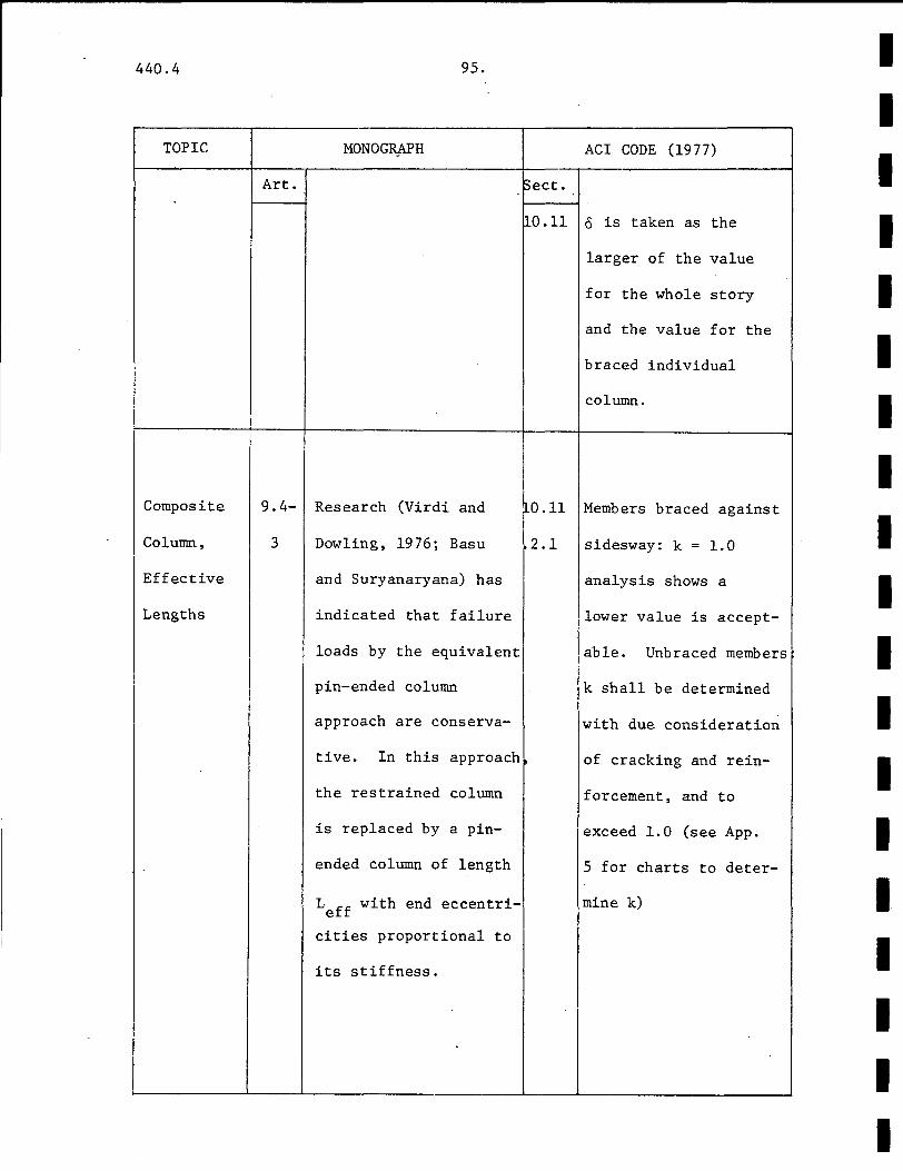
440.4
TOPIC
Composite
Column,
Effective
Lengths
95.
MONOGR,APH
Art.
9.4- Research (Virdi and
3 Dowling, 1976; Basu
and Suryanaryana) has
indicated that failure
loads by the equivalent
pin-ended column
approach are conserva-
tive. In this approach
the restrained column
is replaced by a pin-
ended column of length
Leff with end eccentri
cities proportional to
its stiffness.
ACI CODE (1977)
~ect.
~0.11 o is taken as the
larger of the value
for the whole story
and the value for the
braced individual
column.
RO.ll Members braced against I 2.1 sidesway: k = 1.0
analysis shows a
llower value is accept-
able. Unbraced members
k shall be determined
with due consideration
of cracking and rein-
forcement, and to
exceed 1.0 (see App.
5 for charts to deter-
mine k)
I I I I I I I I I I I I I I I I I I I
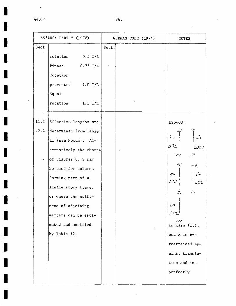
I I I I I I I I I I I I I I ,I I I
440.4
BS5400: PART 5 (1978)
Sect.
rotation 0.5 I/L
Pinned 0.75 I/L
Rotation
prevented 1. 0 I/L
Equal
rotation 1. 5 I/L
11.2 Effective lengths are
.2.4 determined from Table
11 (see Notes). Al-
ternatively the charts
of Figures 8, 9 may
be used for columns
forming part of a
single story frame,
or where the stiff-
ness of adjoining
members can be esti-
mated and modified
by Table 12.
96.
GERMAN CODE (1974) NOTES
Sect.
I
BS5400:
LL1 "":,.< ..
(/) (Ill
0.7L o.85L ,, '? //
.l.,f/ A
(II/) (IV)
I I.OL /.5L
I ~?- 771
I (VJ
!
I 2.oL
77T In case (iv),
end A is un-
. restrained ag-I
I ainst transla-
tion and im-
perfectly
I i

440.4 97 ..
TOPIC MONOGRAPH
Art.
i
I Composite I
19.4- Virdi and Dowling !
Column, I 2 (1975).have proposed i I I
I Slenderness
I a non-dimensional
-Function I slenderness ratio A
I where I
i I I = L/L (9. 23) I e I I L = ~VE I + E I +
I e I ~c c s s
+Acr + c0 u s y
i /F:r I I~)
I A a (9.24) I r Y
I which has the advan-
I that A I tage as c
approaches zero, I con-I
I verges to the value for I
I bare steel colunms.
I -I Short Columns: A < 0.2 • I
l I Long Columns: X > 0.2
Composite
Column,
l
ACI CODE (1977)
~ect.
I ' i I
I I
10.14 j_2E I + E I s t r < c g
.5 - .2E A + E A c g s t
I !
' i i l \
i 1
I I I I I I I I I I I I I I I
I I I
I I I I I I I I I I I I I I I I I I I
440.4
BS5400: PART 5 (1978) --
Sect.
11.3 A = 1eff/LE
LE = ~/(E I + c c
E I + E I /N s s r ·r u
where
E = 450 f c cu
N is obtained from u
section 11.14 or I
111. 3.1
lA must be chosen X
smaller than A . y
I I
I I I
I
··-·
98.
GERMAN CODE ( 19 7 4) NOTES
Sect.
restrained
against rota-
tion.
I
I
I
I
I
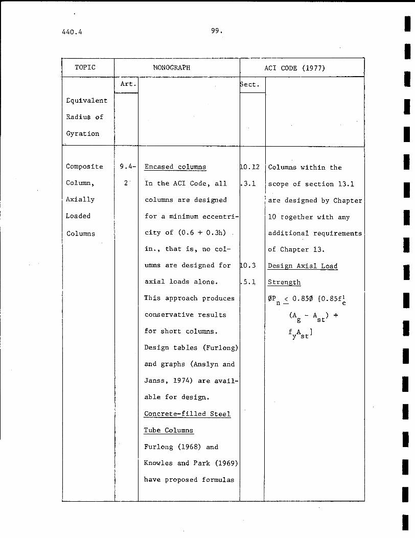
440.4 99.
r-----------.----------·--·-----------------~-----------------------------.
TOPIC
Equivalent
Radius of
Gyration
Composite
Column,
1 Axially
I Loaded I
Columns
MONOGRAPH ACI CODE (1977)
Art. Sect.
9.4- Encased columns ~0.12 Columns within the
2 In the ACI Code, all .3.1 scope of section 13.1
columns are designed are designed by Chapter
for a minimum eccentri- 10 together with any
city of (0.6 + 0.3h) additional requirements
in., that is, no col- of Chapter 13.
umns are designed for ~0.3 Design Axial Load
axial loads alone. .5.~ Strength
This approach produces 0P < 0.850 [0.85f 1 n- c
conservative results
for short columns.
Design tables (Furlong)
and graphs (Anslyn and
Janss, 1974) are avail-
able for design.
Concrete-filled Steel
Tube Columns
Furlong (1968) and
Knowles and Park (1969)
have proposed formulas
I I I I I I I I I I I I I I I I I I I
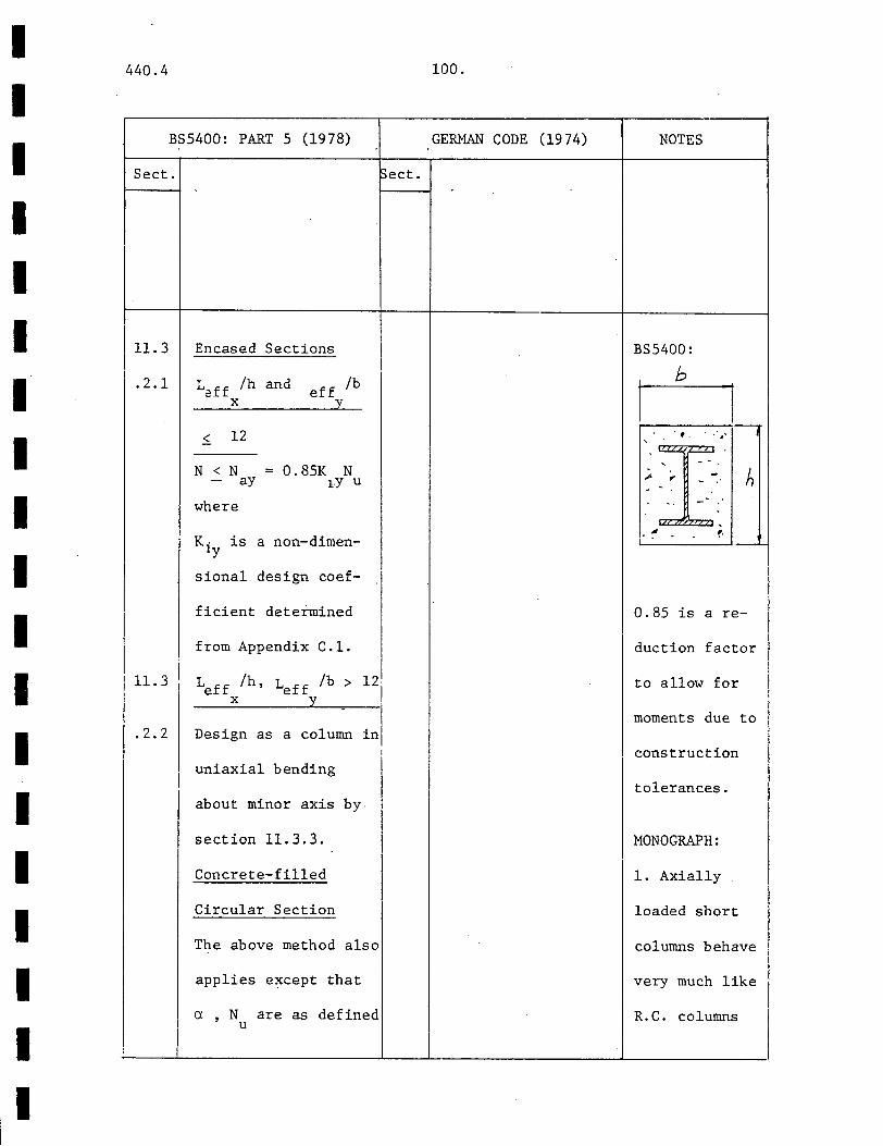
I I I I I I I I I I I I I I I I I I I
'
440.4
BS5400: PART 5 (1978)
Sect.
11.3
.2.1
11.3
.2.2
~ect.
Encased Sections
/h and ff /b 12ff X. e -Y
~ 12
N < N = 0.85K N - ay tY u
where
K· ly is a non-dimen-
sional design coef-
ficient determined
from Appendix C.l.
i Leff /h, Leff /b > 12. I I X -y
-
in I Design as a column
I uniaxial bending
about minor axis by
section 11. 3. 3.
Concrete-filled
Circular Section
The above method also
applies except that
a , N are as defined u
i
100.
GERMAN CODE (1974) NOTES
BS5400:
b
h
....._ ___ ___.,_
0.85 is are-
duction factor
to allow for
moments due to
construction
tolerances.
MONOGRAPH:
1. Axially
loaded short
columns behave
very much like
R.C. columns
101.
TOPIC NONOGRAPH
Art.
for the strengths of
filled columns. The
AIJ method superimposes
the capacities of con-
crete and steel and if
the slenderness ratio I I
I exceeds 50, the axial
I load is increased by I a factor a = 100/(150
I I
I - >..) (9. 44)
Other methods are the
CIDECT method and those
I proposed by Janss and
I Guiax (1970) and Virdi
! and' Dowling (1975).
--
Composite ·l 9.4- Encased Sections
Column, I 3 The ACI method treats I I
Columns i all encased columns as I
in Bending reinforced concrete
I beam-columns, the de-I I I sign of which is based !
I on research by Furlong
I (1967, 1968).
I
ACI CODE (1977) -
~ect.
I I I I
~0.11 If end moments are
.5.4 nearly zero or the
end eccentricities
are small. M2 is
based on a minimum
eccentricity of (0.6 +
0.03h) in equation
(10-6) about each axis
I
I
i I I
I
I
I I i
I
I I I I I I I I I I I I I I I I I I I

I I I I I I I I I I I I I I I I I
440.4
BS5400: PART
Sect.
in section
I I
I
I
102.
5 (1978) GERMAN CODE (19 74)
Sect.
11.3. 7.
I I
I i
I I
I
NOTES
Thus,
p =A CJ + u c u
A0 (9. 22) s y
2. Most of
these methods
use the tan-
gent modulus I I
approach. I The!
I European me-i
thods use the I I I I
European col- I I
umn curves l I
which accountsl I
for initial
structural and
geometrical
imperfections.
MONOGRAPH: p
P/PuU; ~
440.4
TOPIC
Art.
103.
MONOGRAPH
A-column is adequate if
the point defined by
the ultimate axial
load and magnified
ultimate moment falls
within the interaction
curve (see Notes). The
method of BS5400, based
on the work of Basu and
Somerville (1969), uses
an idealized parabolic
approximation to the
axial load-moment inter
action curve. Three
constants K1, K2, K3
are defined and the
strength of the section
is given in terms of
these constants. The
AIJ method is an allow
able load method based
on the fact that the
ultimate strength can be
safely estimated by
Sect.
ACI CODE (1977)
separately. The ratio
Mi/M 2 in equation (lO
ll) is determined as
follows:
a) if end eccentricities
are less than the min
imum, the actual moments
are used.
b) If computations show
zero en~ moments, M1/M2
can be taken as one.
I I I I I I I I I I I I I I I I I I I
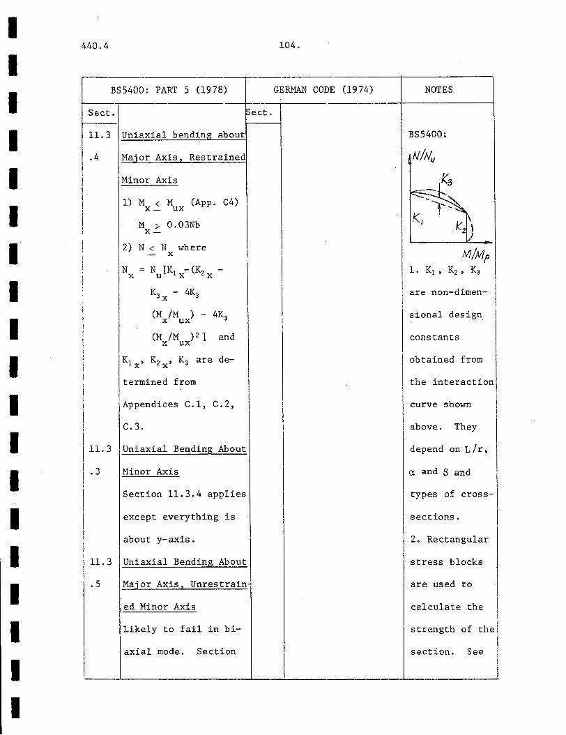
I I I I I I I I I I I I I I I I I I I
440.4 104.
r----------------------r--------BS5400: PART 5 (1978) GERMAN CODE (1974)
Sect. ect.
11.3 Uniaxial bendin about
.4 Ma'or Axis, Restrained
I I
Minor Axis
I 1) M < M (App. C4) I X- ux
I M > 0.03Nb X-
2) N < N where X
lx X X u !
I IN = N [K - (~
K3 - 4K3 X
(M /M ) - 4K3 X UX
(M /M ) 2 ] and X UX
Kl ' K2 ' K3 are de-X X
termined from '·
Appendices C.l, C.2,
C.3. I 11.3 Uniaxial Bending About
I • 3 Minor Axis
Section 11.3.4 applies
except everything is
about y-axis.
11.3 Uniaxial Bending About
. 5 Major Axis, Unrest rain-
ed Minor Axis
Likely to fail in bi-
i axial mode. Section I I
I
NOTES
BS5400:
. ' '
I
are non-dimen- I I I
sional design I
constants I obtained from
the interaction
curve shown
above. They
depend on L /r,
a and B and I
types of cross-
sections.
I 2. Rectangular
stress blocks
are used to
calculate the
strength of the
section. See
440.4 105.
TOPIC MONOGRAPH
Art. Sect.
adding the strengths of
the two components. A
reduction factor is
used on concrete
strength:
f = f (1 - 15 p ) c 1 c s c
(9.26)
Concrete-filled Tubular
Section
9.5-3 The ACI method that
considers all columns as
beam-columns also appli-
es. In the AIJ method,
the provisions for en-
cased columns are also
applicable. The axial
load is magnified by a
factor a(equation 9.44)
if the slenderness ratio
exceeds 50.
Composite 9.4-4 The AIJ Standard for
Column, Structural Calculation
Combined of Steel Reinforced Con-
ACI CODE (1977)
I I I I I I I I I I I I I I I I I I II

I I I I I I I I I I I I I I I I I I I
I I I
I ' I I
I
440.4
BS5400: PART 5 (1978)
Sect.
11.3 .4 (1) should be
satisfied. In addition
N < N xy' see section
11. 3. 6 and N is cal-y
culated from section
I 11. 3. 3 taking M = y
0.03Nb to allow for
construction toler an-
ces.
11.3 Biaxial Bending
.6 1) M < M x- ax
M < M y- ay
2) N < N - xy
where
1 1 1 1 --=-+----N N N N
xy X y ax
!
ld6.
GERMAN CODE (1974) NOTES
~ect.
App. 6.
3. B is the
ratio of the end
moments such
that
-1 < 8 2 1 -!
I i
I
I
I '
I
I

440.4 107.
TOPIC MONOGRAPH
~rt.
Axial Load, crete Structures is the
Bending and only code that considers
Shear this aspect. The prin-
ciple adopted is that
shear failure is to be
prevented until members I !reach flexural capacity.
!
Composite I Column,
I
Cracking
Composite
Column,
Lateral
Reinforcement
ACI CODE (1977)
~ect.
10.14 SEital Rednforcetilent
.7 p > A 1) cl£1) .45(_g-s- A f
10.9 c y
(10-5) .3
110.9 Minimum of 4/6 longi-
.2 tudinal bars must be
I I I I I I I I I I I I I I I I I I I
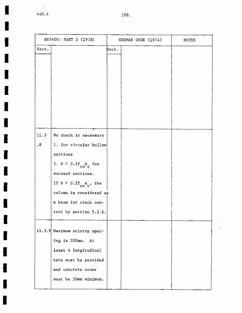
I I I I I I I I I I I I I I I I I
, II
I
440.4
BS5400: PART 5 (1978)
Sect.
11.3 No check is necessary
.8 1. for circular hollow
sections
2. N > 0.2f A for cu c
encased sections.
If N < 0.2f A , the cu c
~ect.
column is considered as
a beam for crack con-
trol by section 5.2.6.
11.3.9 Maximum stirrup spac
ing is 200mm. At
least 4 longitudinal
bars must be provided
and concrete cover
must be 50mm minimum.
108.
GE~~ CODE (1974) NOTES
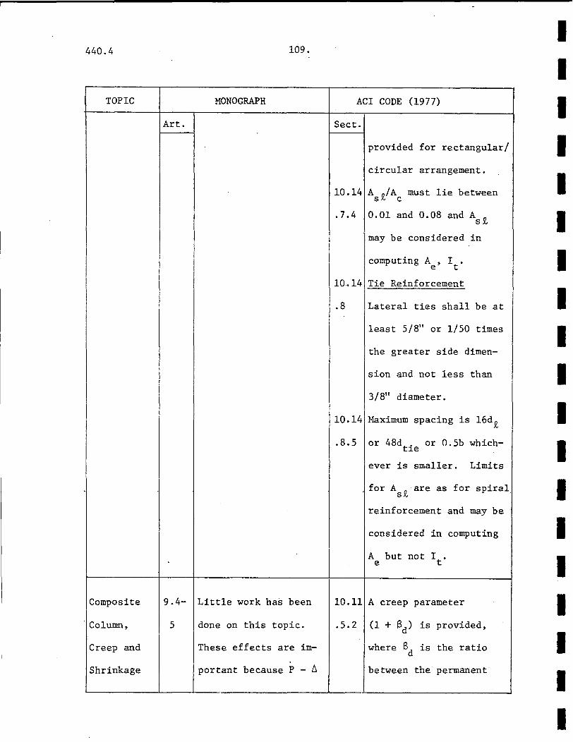
440.4 109.
TOPIC MONOGRAPH
Art.
Composite 9.4- Little work has been
Column, 5 done on this topic.
Creep and These effects are im-
Shrinkage portant because P - ~
ACI CODE (1977)
Sect.
provided for rectangular/
circular arrangement.
10.14 A 0 /A must lie between S.N C
.7.4 0.01 and 0.08 and As~
may be considered in
computing A , I . e t
10.14 Tie Reinforcement
.8 Lateral ties shall be at
least 5/8" or 1/50 times
the greater side dimen-
sion and not less than
3/8" diameter.
10.14 Maximum spacing is 16d.l!,
.8.5 or 48dt. or 0.5b whichJ.e
ever is smaller. Limits
for A 0 are as for spiral S.N .
reinforcement and may be
considered in computing
A but not I • e t
10.11 A creep parameter
.5.2 (1 + Bd) is provided,
where Bd is the ratio
between the permanent·
I I I I I I I I I I I I I I I I I I I
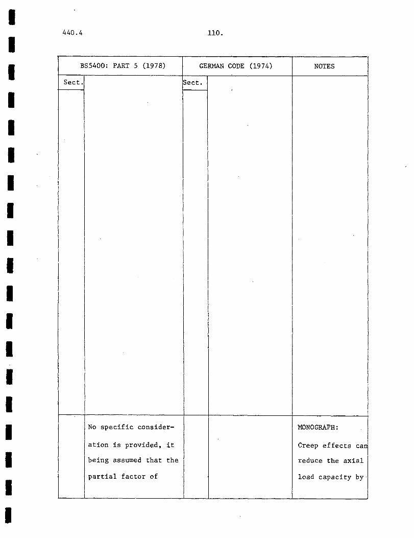
I I I I I I I I I I I I I I I I I I I
440.4
BSS400: PART 5 (1978)
Sect.
I
I I
No specific consider-
at ion is provided, it
being assumed that the
partial factor of
110.
GERMAN CODE (1974) NOTES
Sect.
I
I
I
MONOGRAPH:
Creep effects ca1
reduce the axial
load capacity by·
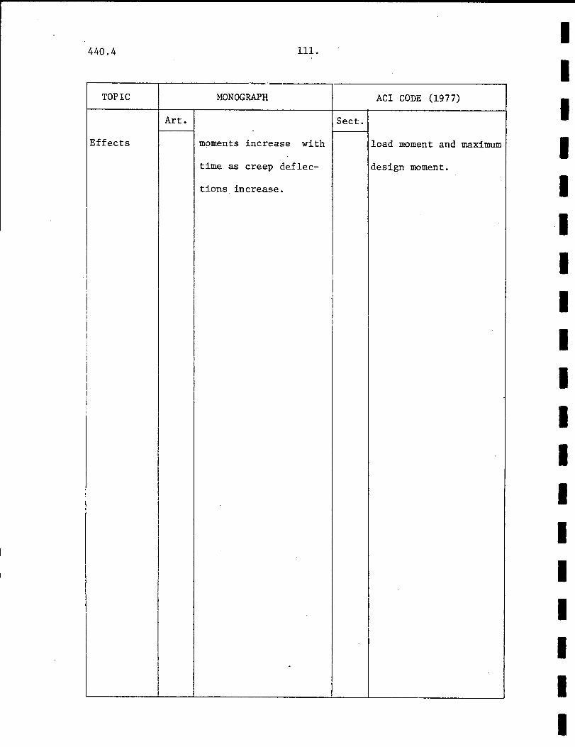
440.4 lll.
·-· TOPIC MONOGRAPH
Art.
Effects moments increase with
time as creep deflec-
tions increase.
I
ACI CODE (1977)
Sect.
load moment and
design moment.
I
maximum
I I I I I ·I I I I I I I I I I I I I I
I I I I I I I I I I I I I I I I I I I
440.4
BS5400: PART 5 (1978)
Sect.
safety for concrete
takes adequate account
of these time-depen-
ent effects.
112.
GERMAN CODE (1974) NOTES
~ect.
as much as 10%
of the short
term axial load
capacity.
I . 440.4 113.
I I I 3. DESIGN EXAMPLES
I I I I I I I I I I I I I I I
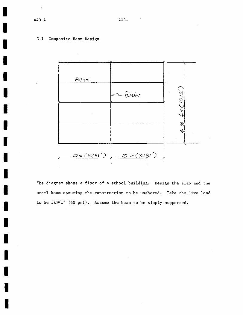
I I I I I I I I I I I I I I I I I I I
440.4 114.
3.1 Composite Beam Design
Be orr) -
~9,t>der
I @J
~! I I
10 m(328!') ~
The diagram shows a floor of a school building. Design the slab and the
steel beam assuming the construction to be unshared. Take the live load
to be 3kN/m2 (60 psf). Assume the beam to be simply supported.

I I I I I I I I I I I I I I I
II
I I I
440.4 115.
AISC SPECIFICATION (1978)
Assume A36 steel is used and 4000 psi concrete.
Using the 7" slab as_designed in the right column, the loads and moments
on the beam are as follows:
Dead Loads
Slab: 150 x 13.12 x 7/12 1.148 k/ft
Beam: Estimated = 0.070 k/ft
Total 1.2.8 k/ft
Moment = 1. 218 (32.81) 2 /8 196 7 k-in
Live Loads
60 X 13.12 = 0.787 k/ft
Moment = (. 787) (32.81) 2 /8 1271 k-in
Total dead and live load 3238 k-in
moment
From ultimate strength considerations, the area of steel required can
be estimated from
A = 2.2·M s --------~~---
where
(0.5d + 0.8t)F y
d = depth of beam, t thickness of slab
and 2.2 is the factor of safety given by allowable stress design (Ref. 15).
A Wl6 x 78 section is adequate with area 23.0 in2 while the formula gives
14.4 in2•
Effective Width of Slab
0.25L 0.25 X 32.81 1 8.2'
16 X 711 + 8.586" = 10'
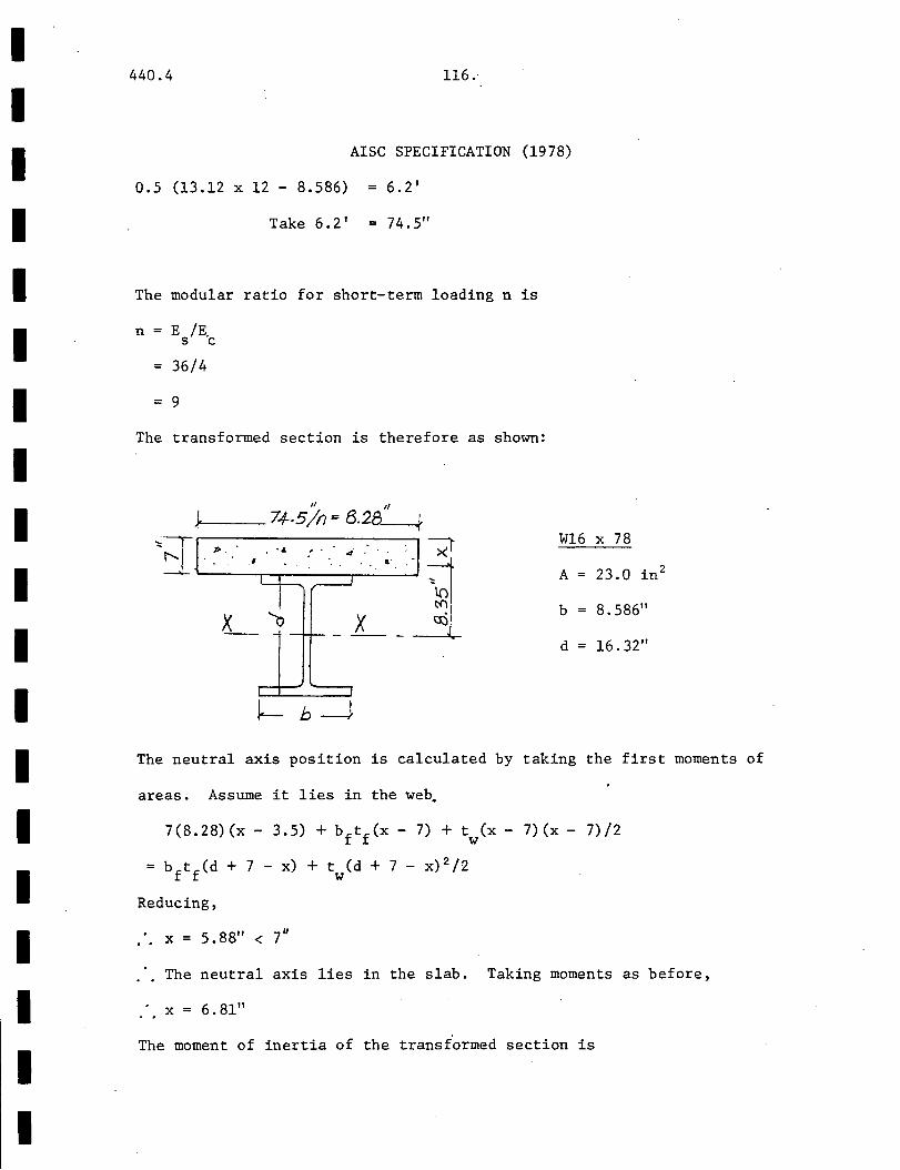
I I I I I I I I I I I I I I I I I I I
440.4 116.
AISC SPECIFICATION (1978)
0.5 (13.12 X 12 - 8.586) 6.2 1
Take 6.2' 74.5"
The modular ratio for short-term loading n is
n = E /E. s c
36/4
= 9
The transformed section is therefore as shown:
II If
74-.5 In= 8.28---+
~·;:r 7 ... , . ·i .
~ ---X_ X ~I
~J .
Wl6
A
b
d
X 78
23.0 • 2 l.n
8.586"
16.32"
The neutral axis position is calculated by taking the first moments of
areas. Assume it lies in the web.
7(8.28)(x- 3.5) + bftf(x- 7) + tw(x- 7)(x- 7)/2
= bftf(d + 7 - x) + tw(d + 7 - x) 2 /2
Reducing,
X = 5.88" < 7u
The neutral axis lies in the slab. Taking moments as before,
X= 6.81"
The moment of inertia of the transformed section is
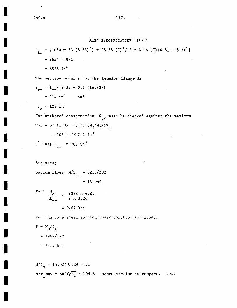
I I I I I I I I I I I I I I I I I I I
440.4 117.
AISC SPECIFICATION (1978)
I tr (1050 + 23 (8.35) 2) + [8.28 (7) 3 /12 + 8.28 (7)(6.81- 3.5) 2
]
2654 + 872
3526 in4
The section modulus for the tension flange is
S = I /(8.35 + 0.5 (16.32)) tr tr
= 214 in 3 and
S 128 in 3
s
For unshored construction. S must be checked against the maximum tr
value of (1.35 + 0.35 (Mr(Mr{)Ss
= 202 in 3 < 214 in 3
.. Take S = 202 in 3
tr
Stresses:
Bottom fiber: M/S tr 3238/202
= 16 ksi
Top: M c
ni tr
3238 X 6.81 9 X 3526
= 0.69 ksi
For the bare steel section under construction loads,
f ~/Ss
1967/128
= 15.4 ksi
d/t = 16.32/0.529 = 31 w
d/t max = 640/fl = 106.6 Hence section is compact. Also w y
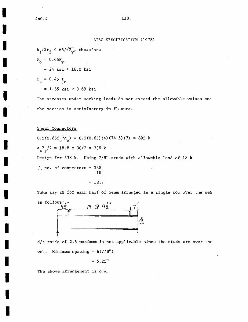
I I I I I I I I I I I I I I I I I I I
440.4 118.
AISC SPECIFICATION (1978)
bf/2tf < 65/~, therefore
F = 0.66F b y
= 24 ksi > 16.0 ksi
f 0.45 f c c
= 1.35 ksi > 0.69 ksi
The stresses under working loads do not exceed the allowable values and
the section is satisfactory in flexure.
Shear Connectors
0.5(0.85f 1A) = 0.5(0.85)(4)(74.5)(7) c c
895 k
A F /2 = 18.8 x 36/2 = 338 k s y
Design for 338 k. Using 7/8" studs with allowable load of 18 k
no. of connectors = 338 18
18.7
Take say 20 for each half of beam arranged in a single row over the web
as follows: 1 " L 92. L
t
I t! t'l @ CJz
,, .!7
I
d/t ratio of 2.5 maximum is not applicable since the studs are over the
web. Minimum spacing 6(7/811)
5.2511
The above arrangement is o.k.
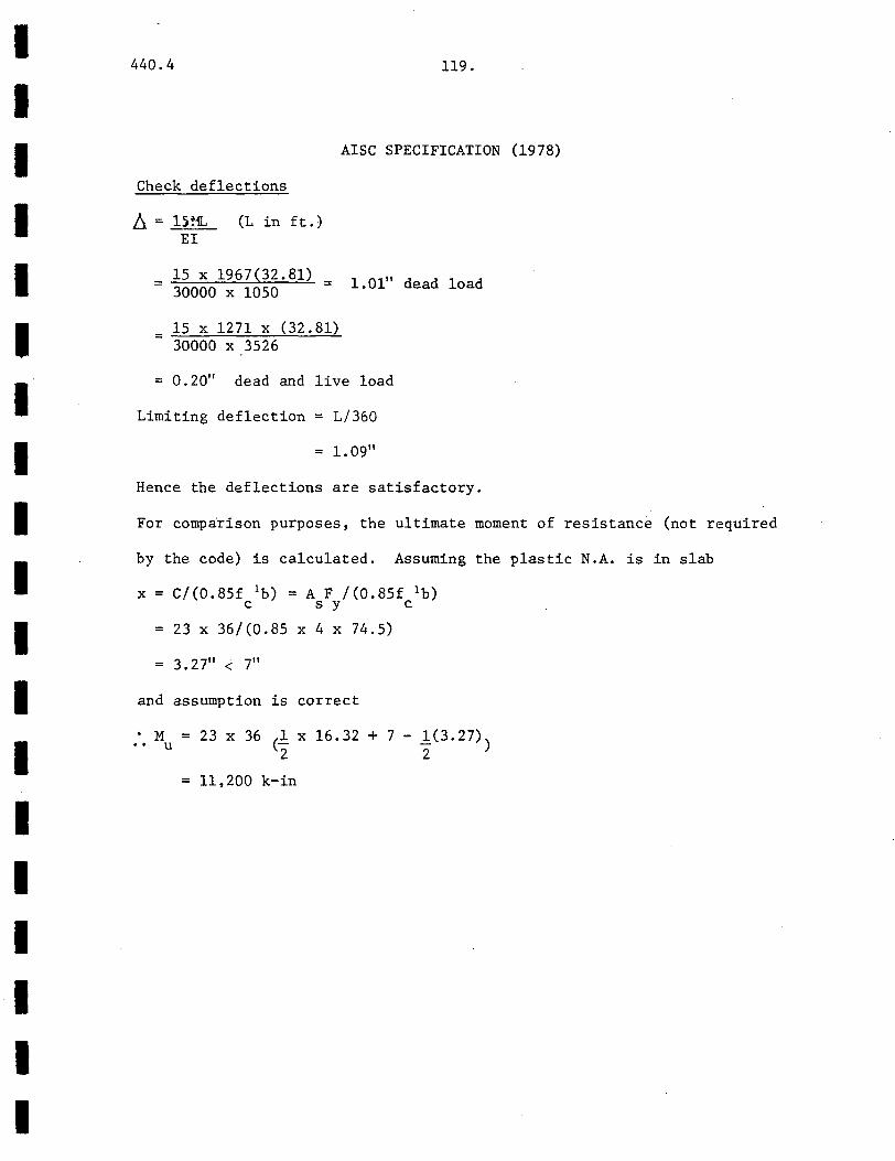
I I I I I I I I I I I I I I I I I I I
440.4 119.
AISC SPECIFICATION (1978)
Check deflections
!J. = l)ffi,
EI (L in ft.)
15 x 1967(32.81) = l.Ol" dead load 30000 X 1050
= 15 X 1271 X (32.81) 30000 X 3526
0.20" dead and live load
Limiting deflection L/360
= 1. 09"
Hence the deflections are satisfactory.
For comparison purposes, the ultimate moment of resistance (not required
by the code) is calculated. Assuming the plastic N.A. is in slab
x = C/(0.85f 1b) = A F /(0.85£ 1b) c s y c
23 X 36/(0.85 X 4 X 74.5)
3. 2 7" < 7"
and assumption is correct
• M •• u = 23 X 36 (l X 16.32 + 7 - 1(3.27)) 2 2
= 11,200 k-in

I I I I I I I I I I I I I I I I I I I
440.4 120.
BS5400: PART 5 (1978)
Assume mild steel reinforcement of f = 250 N/mm2 and 25 N/mm2 concrete. y
Design of Slab
Since 10/4 = 2.5 > 2, the slab is one way spanning by CL.3.4.3.2 of
CPllO. Assume a 175mm slab, 15mm cover and 12mm bars.
L/d 4000/154
= 26 which satisfies CL.3.3.8.1 of CPllO
Dead Loads
Slab: 2.4 x 9.81 x .175 4.12 kN/m
Live Loads
3 k:~/m2 x 1 m = 3.0 kN/m
Gk > Qk use the moments of Table 4
At first interior support moment = FL/9
Using the charts of CPllO: Part 2,
A (reqd) = 616 mm 2 per m s
(1.4 X 4.12.+ 1.6 X 3)4 X 4/9
18.9 kNm per m
Use 12 m @ 175 mm spacing (646 mm2 per m)
Design of Beam
Dead load:
Slab: (1.4 x 4.12 x 4) = 23.1 kN/m
Beam: Estimated = 2 kN/m
Total = 25.1 k /m
Live:
1.6 X 3 X 4 19.2 kN/m

I I I I I I I I I I I I I I I I I I I
440.4 121.
BS5400: PART 5 (1978)
Dead moment = i(25.1)(10) = 314 kN m
Live moment = i(l9. ~) (10) 240 kN m
Total Ultimate _mmt. = 564 kN m
Total Shear = 222 kN
Using the formula on the left to estimate As' try UB412 x 153 x 67 kg/m
with area 8530 Iniif ( 4600nnn2 from the formula) •
From CL.6.2.3.1 (Compact Section)
L/6 = 1.67m < 2m
Effective breadth= 2 x 1.67m = 3330 mm
Check compactness requirements by CL.6.2.2.1. Assume Grade 43 steel
b/t = 153/16 = 9.6 < 16.8 o.k.
d/w = 412/9.4 = 44 < 70 o.k. (for 0 0).
Hence section is compact.
I 3330 .,
tCI . o, • 0 , ~ I ' ' Q ' " 1 a. • tJ . . 6 .
• 4 . •· . . . ~ . ~
J}5 ~ 8 5 30mmZ
Ix = 2 3 '800.cm 1-(\1 X- -X tr :;ftPmm ....... ~ tw = '1.4 mm
153 I Assuming the plastic neutral axis is within the slab.
0.4(3330) X 25y = 0.87 X 8530 X 350
y = 78nnn <"175mm

I I I I I I I I I I I I I I I I I I I
440.4 122.
BS5400: PART 5 (1978).
Assumption is correct.
M = 0.87 f A (d + d - l y) p ys-z s 2
= 0.87 X 8530 X 350(342) Nmm
= 888 kNm > 564 kNm
From CL.6.2.3.2
Shear Strength= 0.38 x 350 x 412 x 9.4 1.1
= 714 kN > 222 kN
Hence the section is satisfactory.
Shear Connectors
To design the connectors, the longitudinal shear flow must be calculated
(CL.5.3.1) by elastic theory (VQ/I). With a modular ratio of 7.5 the
transformed section is as follows:
~ -3080/7.5 = 444 mm
r
l.N . . , . . . c. .. .Ji.L. ~ . 0. . . . . !_ . . . . 0.
· •. tJ • •• .o. : . tJ : •. : ~ :,.· .. ~:
-----~
New effective width = 3080 mm (CL.5.3.1)
Assume the elastic neutral axis is inside the slab, by taking moments
of areas ,
.". x = 117 mm
Assumption is correct.
I comp 4
= 23800 X 10 + 8530 (323)2 + [444(175)
3 /12 + 444 (175(117- 175)
2]
2
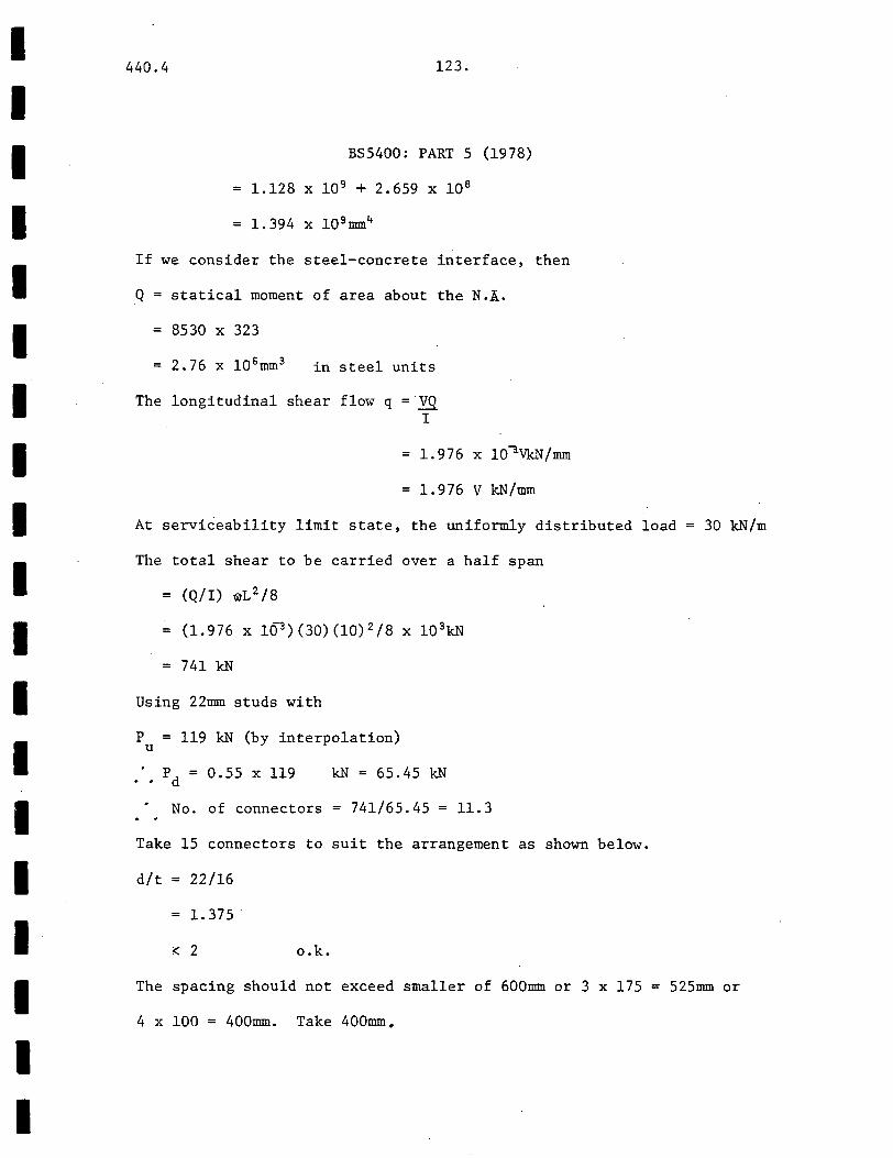
I I I I I I I I I I I I I I I I I I I
440.4 123.
BS5400: PART 5 (1978)
= 1.128 X 10 9 + 2.659 X 10 8
= 1. 394 x 109mm4
If we consider the steel-concrete interface,
Q = statical moment of area about the N .!,.
8530 X 323
in steel units
The longitudinal shear flow q = YQ I
then
= 1.976 x lO~VkN/mm
= 1. 976 V k.N/mm
At serviceability limit state, the uniformly distributed load 30 k.N/m
The total shear to be carried over a half span
= (Q/I) 1WL 2 /8
= (1.976 X 10³ )(30)(10) 2 /8 X 1Q 3k.N
= 741 k.N
Using 22mm studs with
P = 119 kN (by interpolation) u
p = 0.55 X 119 d
k.N = 65.45 kN
No. of connectors = 741/65.45 = 11.3
Take 15 connectors to suit the arrangement as shown below.
d/t = 22/16
1. 375 .
< 2 o.k.
The spacing should not exceed smaller of 600mm or 3 x 175 =
4 x 100 = 400mm. Take 400mm.
525mm or
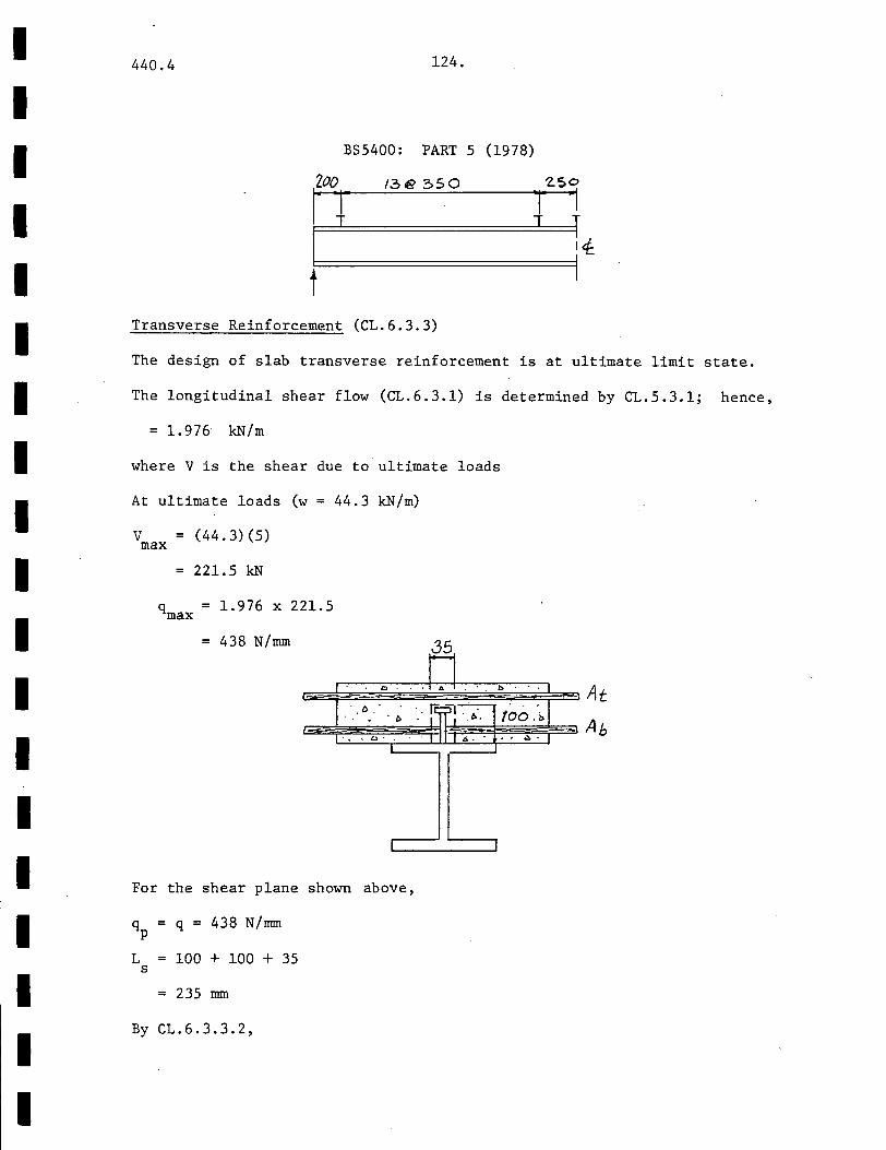
I I I I I I I I I I I I I I I I I I I
440.4 124.
BS5400: PART 5 (1978)
Zoo 13€ 350
itf
t Transverse Reinforcement (CL.6.3.3)
The design of slab transverse reinforcement is at ultimate limit state.
The longitudinal shear flow (CL.6.3.1) is determined by CL.5.3.1; hence,
1. 976 kN/m
where V is the shear due to ultimate loads
At ultimate loads (w = 44.3 kN/m)
v (44.3)(5) max
221.5 kN
1.976 X 221.5
438 N/mm
I
For the shear plane shown above,
q = q = 438 N/mm p
L 100 + 100 + 35 s
= 235 mm
By CL.6.3.3.2,
I
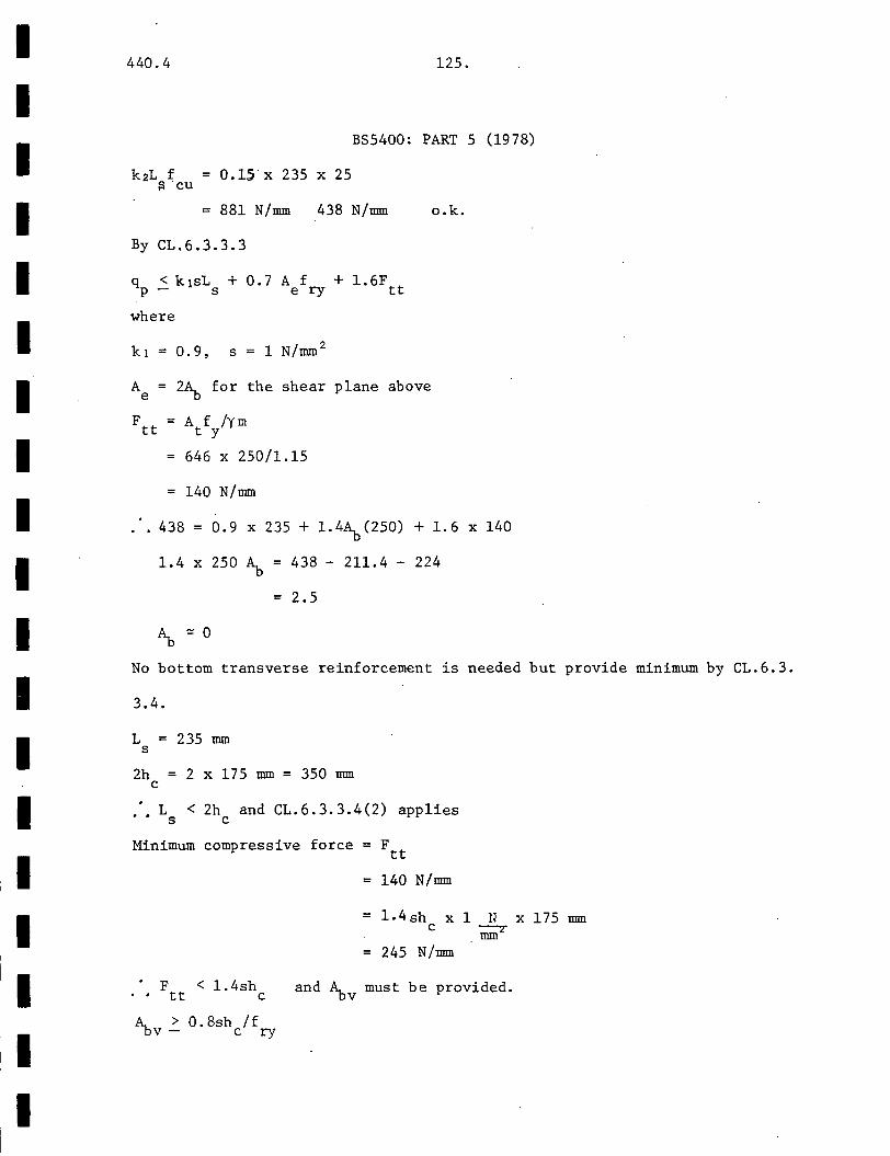
I I I I I I I I I I I I I I I I I I I
440.4
k2L f = 0.15 X 235 X 25 ::> cu
125.
BS5400: PART 5 (1978)
= 881 N/mm 438 N/mm o.k.
By CL.6.3.3.3
where
k1 = 0.9, s = 1 N/mm 2
A e
2~ for the shear plane above
= A f /ym t y
646 X 250/1.15
= 140 N/mm
438 0.9 X 235 + 1.4~(250) + 1.6 X 140
1.4 X 250 ~ 438 - 211.4 - 224
2.5
No bottom transverse reinforcement is needed but provide minimum by CL.6.3.
3.4.
L 235 mm s
2h 2 x 175 mm = 350 mm c
.'. L < 2h and CL.6.3.3.4(2) applies s c
Minimum compressive force = Ftt
. F tt
< 1. 4sh c
A. > 0.8sh /f -DV- c ry
= 140 N/mm
= 1.4 sh c
X 1 N X 175 rom mm2
= 245 N/mm
and ~v must be provided.

I I I I I I I I I I I I I I I I I
440.4 "126.-
BS5400: PART 5 (1978)
= 0.8 X 1 X 175/250 X 1000
560 mm2 /m
Provide say 12 mm@ 200 mm (565 mm 2 /m)
Check on Deflection
6 = 5wL 384EI
= 5 X 17.9 X 10~ X (10 3) 3 rom 384 X 200 X 23800 X 104
= 49 mm (span/205) for dead load which is not acceptable
b:, = 5 X 12.1 X 10- 3
384 X 200 X 1.394 X 10 9
= 6 mm (< span/1000) for live load which is acceptable
To reduce the dead load deflections to an acceptable value, it will
probably be necessary to use propped construction.
I I I I I I I I I I I I I I I I I I I
440.4 127.
3.2 Composite Column Design
Design a concrete-encased steel section for
at ultimate conditions. The column is pin-ended
and fix-ended (against rotation and translation)
and is also braced against sidesway. Bending is
the following loads
about the x-x axis
about the y-y axis
about the x-x axis.
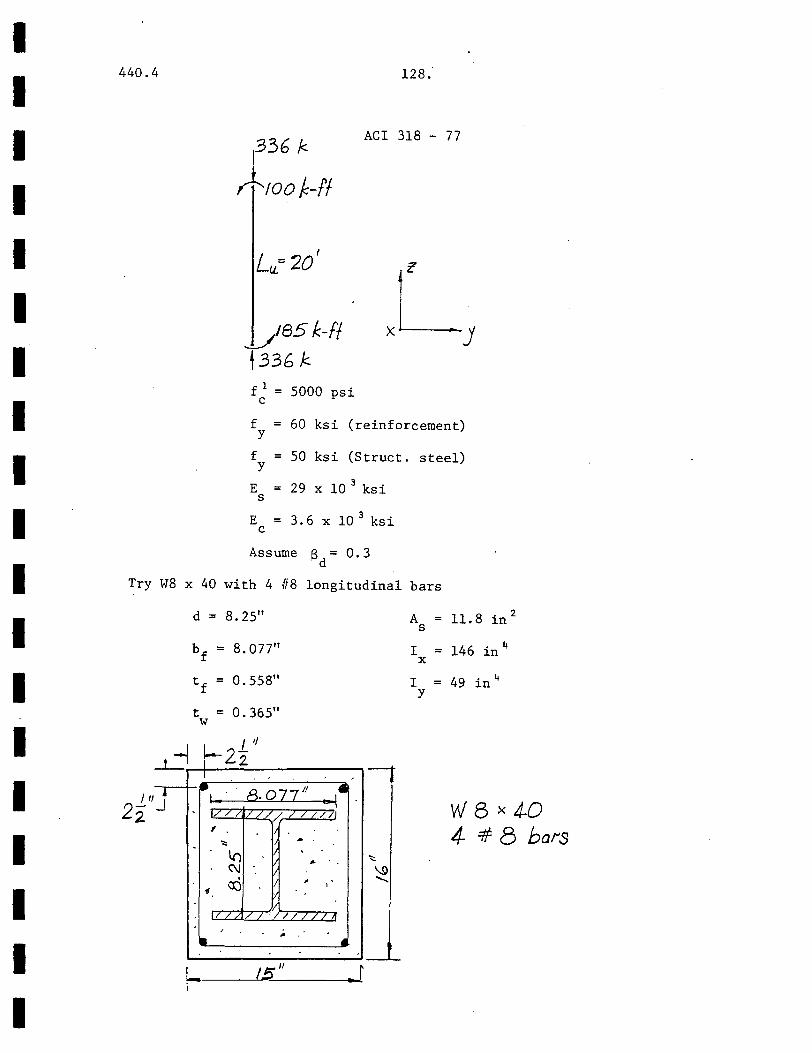
I I I I I I I I I I I I I I I I I I I
440.4 128.
ACI 318 - 77
vesk-ff t33G k f 1 = 5000 psi
c
f = 60 ksi (reinforcement) y
f = 50 ksi (Struct. steel) y
E = 29 X 10 3 ksi s
E = 3. 6 X 10 3 ksi c
Assume B = 0. 3 ·d
Try W8 x 40 with 4 #8 longitudinal bars
d = 8.25" A ll.8 in 2 = s
b = 8. 077" I 146 in If = f X
t = 0.558" I = 49 in 4 f y
t = 0.365" w
__t_ I I
,,, 22 J
, . 8. OZ1'' -1. 1-~~ / LL /_!J W8x4-Q ~
'::: .. 4- =# 8 bat'S -
lr) . <\1 .
~ ,.
1 ;
//1/ /If / ;. ._ __.
~----~'s~"----~~~r

I I I I I I
II I I I I I I I I I
440.4 129.
ACI 318 - 77
Since the column is braced, the effective length factor k = 1.0
( CL. 10. 11. 2. 1) .
r = 0.3 x 16" = 4.8" (CL.lO.ll. 3)
By CL.l0.14.5, the maximum value of r is
r max
E I /5 + E I - c g s t - E A /5 + E A
c g s t
=/·3.6 X 15 X 16 3 /(12 X 5) + 29 X 146. 3.6 X 15 X 16/5 + 29 X 11.8
= 3.9 in
Take r 3. 9"
k'~ . 1. 0 X 20 1
u
20'
ktu/r = 20 x 12/3.9
= 61.5
34 - 12 (-100/185)
40.5
• Slenderness must be considered (CL.l0.11.4.1)
EI = E I /5 + E I
c g s t 1 + . Bd
3.6 X 103 X 5120/5 + 29 X 103 X 146 1.3
= 6.09 x 10⁶ kin
P = ~ 2EI/(k~ )2 c u
= ~2(6.09 X 10⁶)/(20 X 12)2
1044 k
CJ = 0. 70
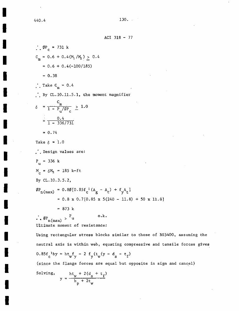
I I I I I I I I I I I I I I I I I I I
440.4 130.
ACI 318 - 77
. ~p = 731 k . • c
em = o. 6 + o. 4 (M1 /~ ) ~ o. 4
0.6 + 0.4(-100/185)
0.38
Take C = 0.4 m
By CL. 10. 11. 5. 1, the moment
c m 1.0 0 1 - p /C/JP > u c
0.4 = 336/731 1 -
= 0.74
Take o = 1.0
• •• Design values are:
p 336 k u
M o~ c 185 k-ft
By CL.l0.3.5.2,
magnifier
0.8~[0.85f 1 (A - At) + fA ] c g y t
= 0.8 X 0.7(0.85 X 5(240- 11.8) +50 X 11.8]
= 873 k
• p " ~p ( ) > u n max
o.k.
Ultimate moment .of resistance:
Using rectangular stress blocks similar to those of BS5400, assuming the
neutral axis is within web, equating compressive and tensile forces gives
0.85f lby = ht f - 2 f (t (y - d - tf) c w y y w s
(since the flange forces are equal but opposite in sign and cancel)
Solving, ht + 2 (d + tf) w s y· = --------~-----b + 2t p w
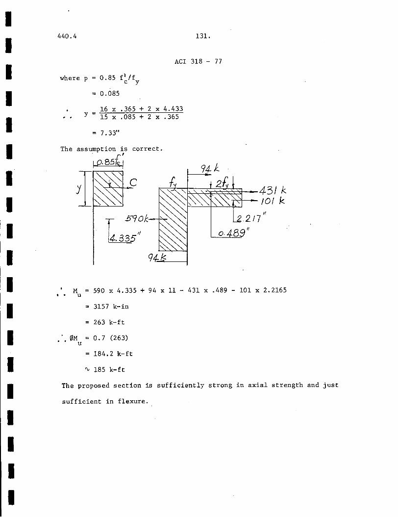
I I I I I I I I I I I I I I I I I I I
440.4 131.
ACI 318 - 77
where p = 0.85 f 1 /f c y
= 0.085
16 X .365 + 2 X 4.433 y = 15 X .085 + 2 X .365
= 7.33"
correct.
~~~~~~43/k -r-H---!0/ k
1-'----'-~~~_.J
6590/:.
1/
5 o. 89"
M = 590 X 4.335 + 94 X 11 - 431 X .489 - 101 X 2.2165 • • u
= 3157 k-in
263 k-ft
• 0M = 0 . 7 ( 2 6 3) • • u
184.2 k-ft
'\.. 185 k-ft
The proposed section is sufficiently strong in axial strength and just
sufficient in flexure.

I I I I I I I I I I I I I I I I I I I
440.4 132.
BS5400: PART 5 (1978)
L = b./m
JJ52 tNm
Tsao kN f = 30 N/mm2
cu
f = 410 N/mm2 ry
f = 350 N/mm2 y
E = 200 kN /mm2 s
E = 27 kN/mm2 c
f = 30 N/mm2 > 25 N/mm2 cu
Therefore, concrete is satisfactory CL.11.1.2.2)
Try UC 206 x 204 x 52 kg/m with 4 No. 25mm bars:
d = 206 mm
bf = 204 mm
tf = 12.5 mm
t = 8 mm
A = 6640 mm2
s
I = 5263 cm4 X
I = 1770 cm4 y
w .
~------------~tL35
• f
325
uc 206 x204x52 k.s/m 4 Nos 25 mm bars
I I I I I I I I I I I I I I I I I I I
440.4 133.
BS5400: PART 5 (1978)
Concrete cover to nearest structural steel member surface = 1 2(325 - 206)nun
( CL. 11. 3. 9) = 59 . Snun > 50mm o. k.
N 0.91A f + 0.87A f + 0.45A f u s y r ry c cu
= 0.91(6640)(350) + 0.87(4 ~(25) 2 )(.410) + 0.45(325) 2 (30) X 10- 3 kN 4
= 2115 + 700 + 1426 kN
4241 kN
0.45 A f /N c cu u
= 1426/4241
0.34 which lies between the limits of 0.15 and 0.8 ( CL . 11. 1. 4)
From CL.ll.2.2.4, the effective length is taken to be
1.01 = 6.lm = 6100nun
6100/325 = 18.8 < 30 hence slenderness limit is o.k. (CL .11.1. 5)
The column self-weight by CL.ll.2.2.6 = 2.4 x 6.1 x 3252 x 9.81 kN
By CL.ll.3.1,
Similarly,
15 kN
= 1% of axial load and hence
is negligible.
L = ~[(E I + E I + E I )/N ]1
/2 Ex c ex s sx r rx u
LEx = 9888 nun
A = 6100/9888 X
0.62
L'~<' 9028 ~Y
A y 0.7 X 6100/9028 = 0.48
o.k.
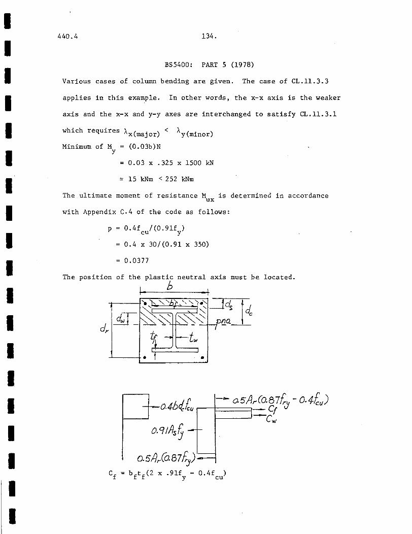
I I I I I I I I I I I I I I I I I I I
440.4 134.
BS5400: PART 5 (1978)
Various cases of column bending are given. The case of CL.ll.3.3
applies in this example. In other words, the x-x axis is the weaker
axis and the x-x and y-y axes are interchanged to satisfy CL.ll.3.1
which requires A ( . ) < A x maJor y(minor)
Minimum of M (0.03b)N y
= 0.03 X .325 X 1500 kN
~ 15 kNm < 252 kNm
The.ultimate moment of resistance M is determined in accordance ux
with Appendix c.4 of the code as follows:
p 0.4f /(0.91£ ) cu y
0.4 X 30/(0.91 X 350)
0.0377
The position of the plastic neutral axis must be located.
1- h
--'-----+• •
0.9 1115 ~
0. 5/Jr(o. 8 7/i.J) bftf(2 X .9lf - 0.4f ) y cu
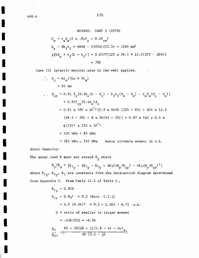
I I I I I I I I I I I I I I I I I I I
440.4 135.
BS5400: PART 5 (1978)
C = t d (2 X .9lf - 0.4f ) w w w y cu
As - 2b ftf = 6640 - 2 (204) (12. 5) 1540 nnn2
p[bds + tf(b- bf)] = 0.0377[325 x 59.5 + 12.5(325- 204)]
= 786
Case (3) (plastic neutral axis in the web) applies.
d = h t I (b p + 2 t ) c w w
= 92 nnn
Muy = 0.91 fy[0.5As(h- de)- bftf(ds- dw) - twdw(dc- dw)]
+ 0.87f (0.4A )d ry r r
Axial Capacity:
0.91 X 350 X 10 6 (0.5 X 6640 (325 - 92) - 204 X 12.5
(59.5 - 20) - 8 X 20(92 - 20)] + 0.87 X 410 X 0.5 X
~(25)2 X 255 X 10-6
210 kNm + 82 kNm
29 2 kNm > 252 kNm hence ultimate moment is o.k.
The axial load N must not exceed N where y
N /N = [i<1 --·- (K1 - K2 - 4K3).(M /M ) - 4K3(M /M ) 2] y u y y y y uy y uy
where K1 , K2 , K3 are constants from the interaction diagram determined y y
from Appendix C. From Table 14.2 of Table C,
K1 0. 828 y
K20 = 0.9a2 + 0.2 (Sect. C.2.1)
0.9 (0.34) 2 + 0.2 = 0.302 < 0.75 o.k.
8 ratio of smaller to larger moment
-136/252 -0.54
K2 90- 25(28- 1)(1.8- a)- C4A = ( X]
K 20 30 (2.5- B)
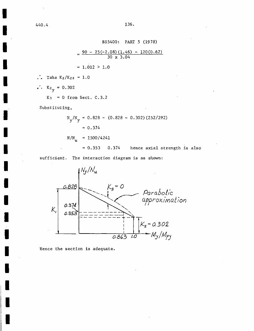
I I I I I I I I I I I I I I I I I I I
440.4 136.
BS5400: PART 5 (1978)
= ..:_9..::_0 _-_2,::_5 (_,_-_2_. 0.;;....8--<,.)__,.(=1.;._. 4.;.....6...:....) _-___;:;1;.._2 0..:_(.:....:;0_. _6 2~) 30 X 3.04
= 1.012 > 1.0
K2 = 0.302 y
K3 = 0 from Sect. C.3.2
Substituting,
sufficient.
k,
N /N = 0.828- (0.828- 0.302)(252/292) y y
= 0.374
N/N = 1500/4241 u
= 0.353 0.374 hence axial strength is also
The interaction diagram is as shown:
0.863 /.0
Pora.Dol/c approx.imat ion
Hence the section is adequate.

I I 440.4 137.
I 4. APPENDICES
I I I I I I I I I I I I I I I I
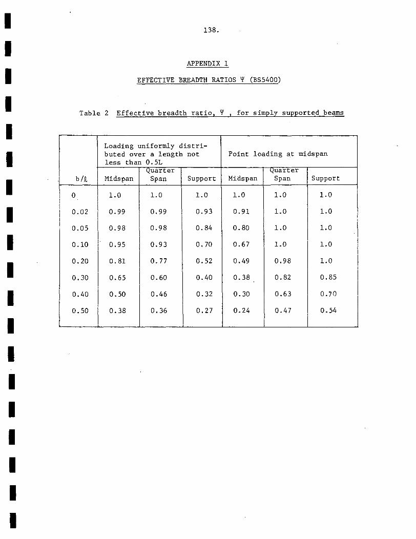
I I I I I I I I I I I I I I I I I I I
138.
APPENDIX 1
EFFECTIVE BREADTH RATIOS ~ (BS5400)
Table 2 Effective breadth ratio, ~ for simply supported beams
Loading uniformly distri-buted over a length not Point loading at midspan less than 0.51
Quarter Quarter b/9., Midspan Span Support Midspan Span Support
0 1.0 1.0 1.0 1.0 1.0 1.0
0.02 0.99 0.99 0.93 0.91 1.0 1.0
0.05 0.98 0.98 0.84 0.80 1.0 1.0
0.10 0.95 0.93 0.70 0.67 1.0 1.0
0.20 0.81 0. 77 0.52 0.49 0.98 1.0
0.30 0.65 0.60 0.40 0.38 0.82 0.85
0.40 0.50 0.46 0.32 0.30 0.63 0. 70
0.50 0.38 0.36 0.27 0.24 0.47 0.54
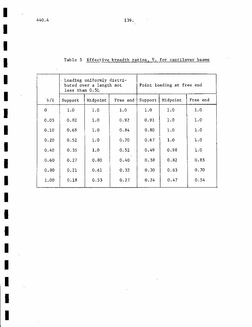
I I I I I I I I I I I I I I I I I I I
440.4
b/2
0
0.05
0.10
0.20
0.40
0.60
0.80
1.00
139.
Table 3 Effective breadth ratios, ~. for cantilever beams
Loading uniformly distri-buted over a length not Point loading at free end less than 0.5L
Support Midpoint Free end Support· Midpoint Free end
1.0 1.0 1.0 1.0 1.0 1.0
0.82 1.0 0.92 0.91 1.0 1.0
0.68 I 1.0 0.84 0.80 1.0 1.0
0.52 1.0 0.70 0.67 1.0 1.0
0.35 1.0 0.52 0.49 0.98 1.0
0.27 0.80 0.40 0.38 0.82 0.85
0.21 0.61 o. 32 0.30 0.63 0.70
0.18 0.53 0.27 0.24 0.47 0.54
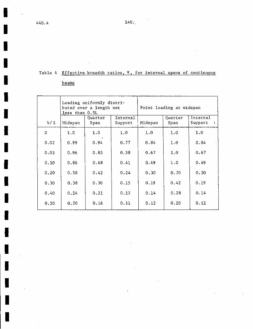
I I I I I I I I I I I I I I I I I I I
440.4
Table 4
b/ 9v
0
0.02
0.05
0.10
0.20
0.30
0.40
0.50
140."
Effective breadth ratios,~, for internal spans of continuous
beams
Loading uniformly distri-buted over a length not Point loading at midspan less than 0.5L
Quarter Internal Quarter Internal Hidspan Span Support Midspan Span Support I
1.0 1.0 1.0 1.0 1.0 1.0
0.99 0.94 0. 77 0.84 1.0 0.84
0.96 0.85 0.58 0.67 1.0 0.67
0.86 0.68 0.41 0.49 1.0 0.49
0.58 0.42 0.24 0.30 0.70 0.30
0.38 0.30 0.15 0.19 0.42 0.19
0.24 0.21
I 0.12 0.14 0.28 0.14
0.20 0.16 0.11 0.12 0.20 0.12
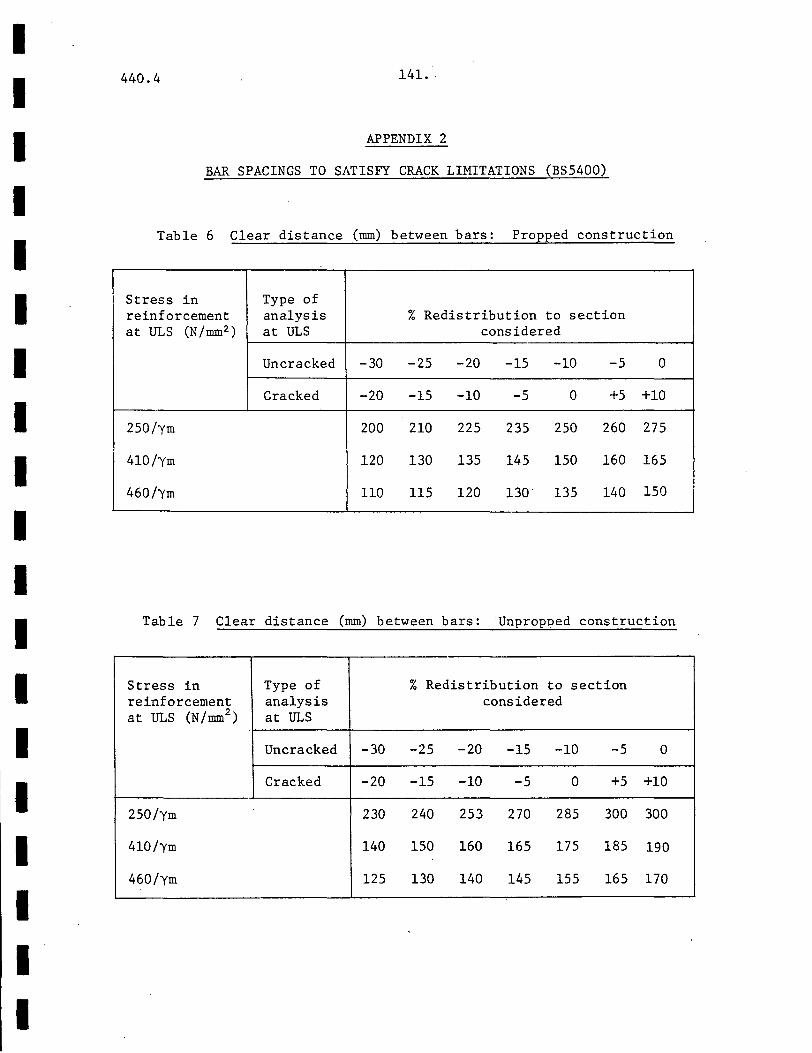
I I I I I I I I I I I I I I
I• I I I I
440.4 141. ·.
APPENDIX 2
BAR SPACINGS TO SATISFY CRACK LIMITATIONS (BS5400)
Table 6 Clear distance (mm) between bars: Propped construction
Stress in Type of reinforcement analysis % Redistribution to section at ULS (N /mm2 ) at ULS considered
Uncracked -30 -25 -20 -15 -10 -5 0
Cracked -20 -15 -10 -5 0 +5 +10
250/ym 200 210 225 235 250 260 275
410/ym 120 130 135 145 150 160 165
460/Ym 110 115 120 13o· 135 140 150
Table 7 Clear distance (mm) bet-v1een bars: Unpropped construction
Stress in Type of % Redistribution to section reinforcement analysis considered at ULS (N/mm2
) at ULS
Uncracked -30 -25 -20 -15 -10 -5 0
Cracked -20 -15 -10 -5 0 +5 +10
250/ym 230 240 253 270 285 300 300
410/ym 140 150 160 165 175 185 190
460/ym 125 130 140 145 155 165 170
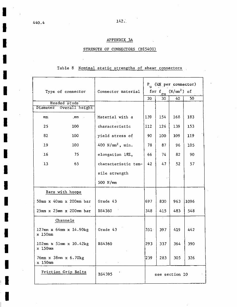
I I I I I I I I I I I I I I I I I
I
440.4 142.-.
APPENDIX 3A
STRENGTH OF CONNECTORS (BS5400)
Table 8 Nominal static strengths of shear connectors
p (kN t>er connector) u Type of connector Connector material for f (N /mrn?) of cu
20 30 40 50 Headed studs
DiameteJ; Overall height
nun .nun Material with a 139 154 168 183
25 100 characteristic 112 126 139 153
82 100 yield stress of 90 100 109 119
19 100 400 N/nun2 , min. 78 87 96 105
16 75 elongation 18%, 66 74 82 90
13 65 characteristic ten- 42 47 52 57
sile strength
500 N/nnn
Bars with hoops
50nun x 40nnn x 200nun bar Grade 43 697 830 963 1096
25nun x 25nnn x 200nnn bar BS4360 348 415 483 548
Channels
127mrn x 64nnn x 14.90kg Grade 43 351 397 419 442 x 150mm
102nnn x Slmm x 10.42kg BS4360 293 337 364 390 x 150nnn
I 76mm x 38nnn X 6.7Qkg 239 283 305 326 x 150mm
Friction Grip Bolts BS4395 I see section 10
I
I I I I I I I I I I I I I I I I I I I
440.4 143.
NOTES:
1. f is the characteristic concrete cube strength at 28 days cu
2. Strengths for concrete of intermediate grade may be obtained
by linear interpolation.
3. For bars and channels of different lengths than those above,
strengths are proportional to the lengths greater than lOOmm.
4. The strength of stud connectors of overall height greater than
lOOmm is taken as the value from the table for lOOmm stud
connectors, unless otherwise determined from pushout tests
according to section 5.3.3.4.

I I I I I I I I
I I I I I I I I I
440.4 144.
APPENDIX 3B
STRENGTH OF CONNECTORS (AISC)
Table 1.11.4, Allowable horizontal shear loads per connector in kips
for ASTM C33 aggregates
Connector
1/2" dia. x 2" hooked or headed stud
5/ 8" dia. x 2.5" hooked or headed stud
3/4" dia. x 3" hooked or headed stud
7 /8" dia. X 3.511 hooked or headed stud
Channel C3 X 4.1
Channel C4 X 5.4
Channel C5 X 6.7
W = length of channel, in.
Specified compressive strength uf concrete f 1 (ksi)
c
3.0 3.5 > 4.0 -5.1 5.5 5.9
8.0 8.6 9.2
l1.5 12.5 13.3
15.6 16.8 18.0
4.3W 4. 7W 5.0W
4.6W 5.0W 5.3W
4.9W 5.3W 5.6W
These loads are also applicable for studs longer than shown.
Table 1.11.4A, Coefficients for use with concrete made from ASTM C330
aggregates
Specified compressive Air dry unit weight of concrete (pcf)
strength of concrete 90 95 100 105 llO 115 120 f 1 (ksi) c
< 4.0 0.73 o. 76 0.78 0.81 0.83 0.86 0.88 -> 5.0 0.82 0.85 0.87 0.91 0.93 0.96 0.99 -
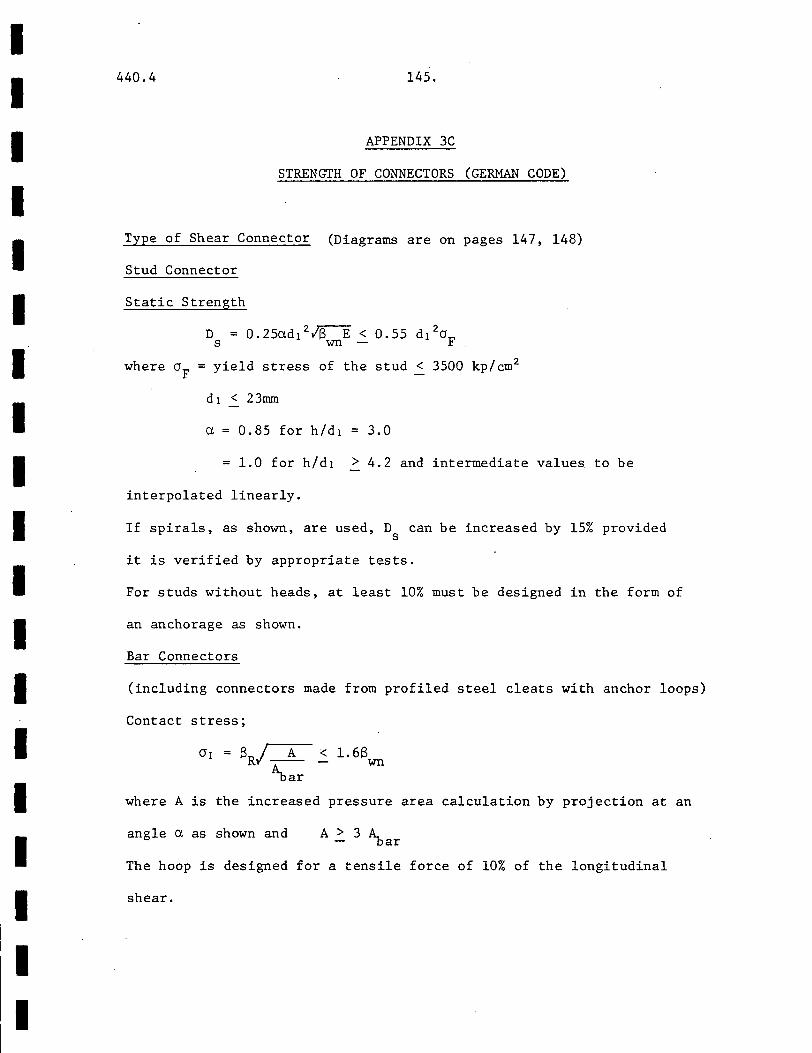
I I I I I I I I I I I I I I I I I I I
440.4 145.
APPENDIX 3C
STRENGTH OF CONNECTORS (GERMAN CODE)
Type of Shear Connector (Diagrams are on pages 147, 148)
Stud Connector
Static Strength
D = 0.25adl 2 ;s-:E < 0.55 d1 2aF s wn -
where aF =yield stress of the stud < 3500 kp/cm2
d1 < 23mm
a 0.85 for h/d1 3.0
1.0 for h/d1 > 4.2 and intermediate values·to be
interpolated linearly.
If spirals, as shown, are used, D can be increased by 15% provided s
it is verified by appropriate tests.
For studs without heads, at least 10% must be designed in the form of
an anchorage as shown.
Bar Connectors
(including connectors made from profiled steel cleats with anchor loops)
Contact stress;
< 1.68 wn
where A is the increased pressure area calculation by projection at an
angle a as shown and A > 3 A_ - -oar
The hoop is designed for a tensile force of 10% of the longitudinal
shear.
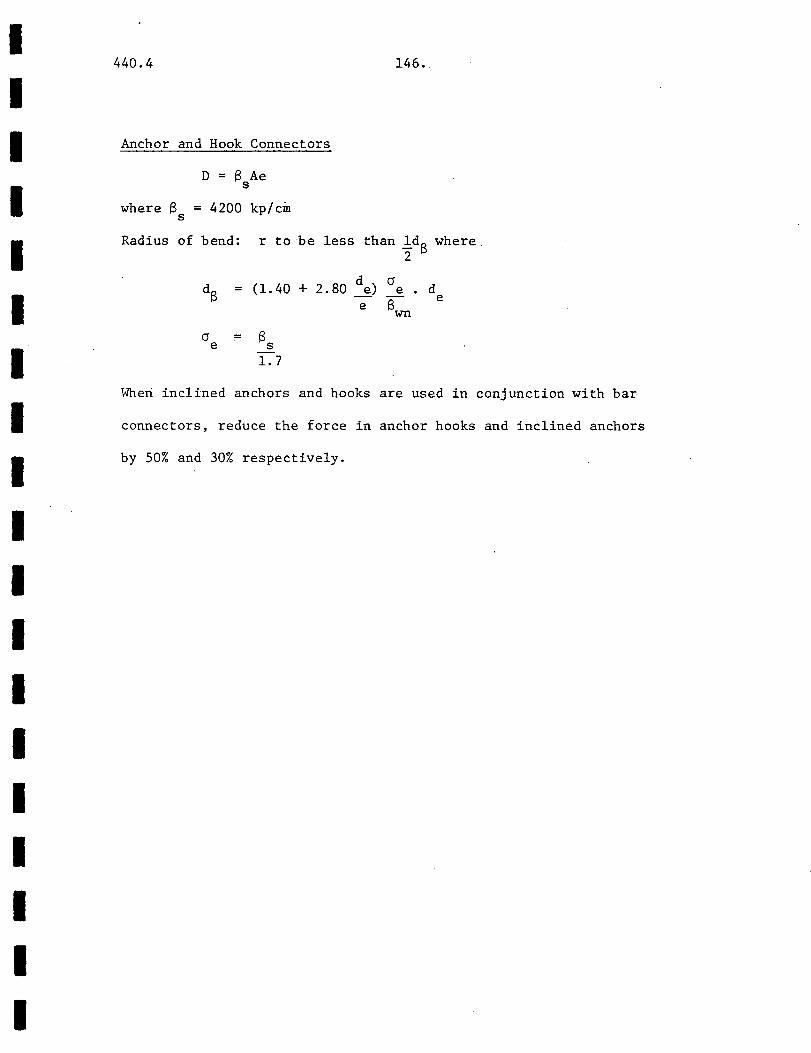
I I I I I I I I I I I I I I I I I I I
440.4
Anchor and Hook Connectors
D = B Ae s
where B = 4200 kp/cm s
146.
Radius of bend: r to be less than ldB where 2
d a (1.40 + 2.80 ~) e
e Bwn d
e
Wheri inclined anchors and hooks are used in conjunction with bar
connectors, reduce the force in anchor hooks and inclined anchors
by 50% and 30% respectively.
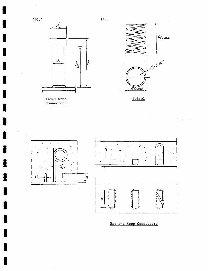
I I I I I I I I I I I I I I
:I I I I I
440.4
d,
I I
Headed Stud Connector
I . . . . ~ , I ~ d
I ..
I I ,e.
I ,~
I . I
. I
147.
81Jmm
Spiral
r,- -h---.---.,.~.-. -~--.~------. ', - (!,
I/ l . · _.
h
Bar and Hoop Connectors

I I I I I I I I I I I I I I I I I I I
440.4
I .
h-[]z: .I
I ' - ~
I ~ ...
b
Connectors Made From Profiled Steel Cleats
With Anchor Loops
•
1 . __
7.. .. . _,.;-:::=. ==-~d) .. . i _Jl_.
I. ~ . . . A ' I _. , "" , Jil •
1
e ,.r •.. , I - . . . .
Anchor and Hook
148.
Calculated Increase Of Stud Pressure Area
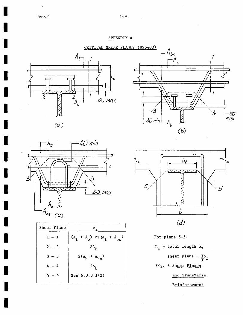
I I I I I I I I I I I I I I I I I I I
440.4
(Q)
Shear Plane
1 - 1
2 - 2
3 - 3
4 - 4
5 - 5
149.
APPENDIX 4
CRITICAL SHEAR PLANES (BS5400)
! 5'0 ftJQ)(
At:>
(A + ~) or (A + ~ ) t t s
2~
2(~ + ~s)
2~
See 6.3.3.1(2)
4{)rn:fJ -A . b (b)
I . b
(d)
For plane 5-5,
L = total length of s
shear plane - lbf 3
Fig. 6 Shear Planes
and Transverse
Reinforcement
!
"4 L:v max

I I I I I I I I I I I I I I I I I I I
440.4
0/j 0
150.
APPENDIX 5
EFFECTIVE LENGTH FACTORS (ACI)
- o./
0
o0-
100 50 .30 2o-
fQ.()-
50 -
k ,.--d:J
-'20 10
-5-0 4-.0
3.0
r
+2.0 -~
f- /.5
t La
Braced Frames Unbraced Frames
'¥ Ratio of l:(EI/L ) of compression members to l:(EI/L) of flexural c
members in a plane at one end of a compression member
k = effective length factors
Vi 60() "'"' ;Cf)O .50
-30 ~"-20
-Jo.o
-5.0
----
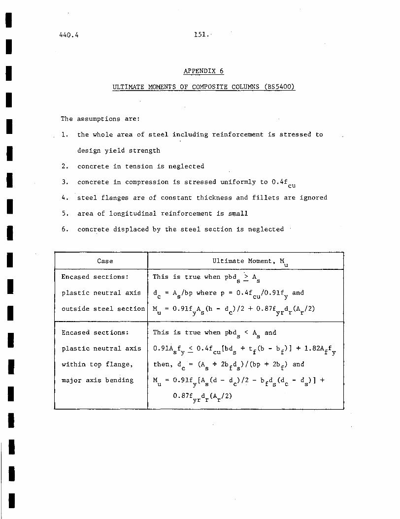
I I I I I I I I I I I I I I I I I I I
440.4 151 ..
APPENDIX 6
ULTIMATE MOMENTS OF COMPOSITE COLUMNS (BS5400)
The assumptions are:
1. the whole area of steel including reinforcement is stressed to
design yield strength
2. concrete in tension is neglected
3. concrete in compression is stressed uniformly to 0.4f cu
4. steel flanges are of constant thickness and fillets are ignored
5. area of longitudinal reinforcement is small
6. concrete displaced by the steel section is neglected
Case
Encased sections:
plastic neutral axis
outside steel section
Encased sections:
plastic neutral axis
within top flange,
major axis bending
Ultimate Moment, M u
This is true when pbd > A s- s
d = A /bp where p = 0.4f /0.9lf and c s cu y
M = 0. 9lf A (h - d )/2 + 0.87f d (A /2) u y s c yr r r
This is true when pbd < A and s s
0.91A f < 0.4f [bd + tf(b- bf)J + 1.82Aff s y- cu s y
then, d = (A + 2bfd )/(bp + 2bf) and c s s
M = 0.9lf [A (d- d )/2- bfd (d -d)]+ u ys c sc s
0.87f d (A /2) yr r r
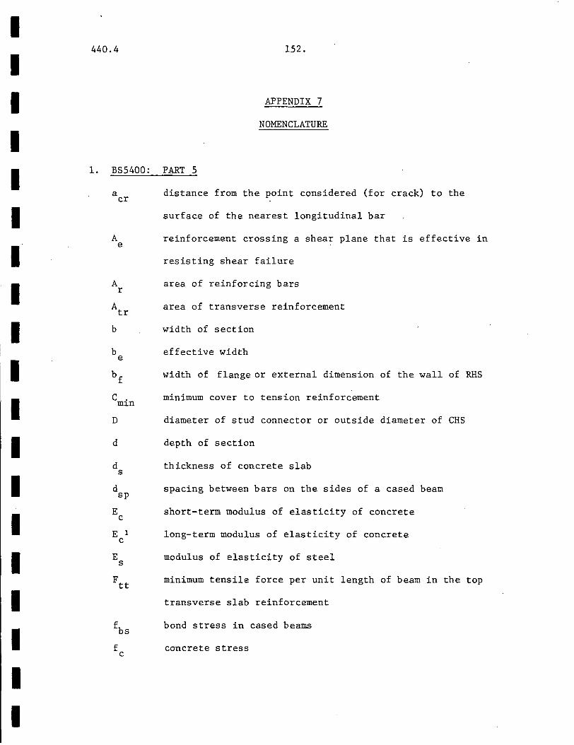
I I I I I I I I I
I I I I I I I I I
440.4 152.
APPENDIX 7
NOMENCLATURE
1. BS5400: PART 5
a distance from the point considered (for crack) to the cr
A e
A r
A tr
b
b e
D
d
surface of the nearest longitudinal bar
reinforcement crossing a shear plane that is effective in
resisting shear failure
area of reinforcing bars
area of transverse reinforcement
width of section
effective width
width of flange or external dimension of the wall of RHS
minimum cover to tension reinforcement
diameter of stud connector or outside diameter of CHS
depth of section
d thickness of concrete slab s
d sp
E c
E 1 c
E s
~s f c
spacing between bars on the sides of a cased beam
short-term modulus of elasticity of concrete
long-term modulus of elasticity of concrete
modulus of elasticity of steel
minimum tensile force per unit length of beam in the top
transverse slab reinforcement
bond stress in cased beams
concrete stress

I I I I I I I I I I I I I I I I I I I
440.4
f cc
f cu
f rs
f ry
frd
f s
f y
f yc
fyd
h
I
L
L s
153.
enchanced characteristic strength of concrete due to tri-
axial containment in CHS
characteristic concrete cube strength at 28 days
limiting stress for steel at ultimate limit state as
specified in Part 3
tensile or compressive stress in reinforcement
nominal yield strength of reinforcement
design yield strength of reinforcement
equivalent steel stress
apparent tensile concrete stress at internal support
due to maximum hogging moment
yield strength of steel
reduced yield strength given by C2
fy
design yield strength of structural steel
greater dimension of rectangular section or overall height
of shear connector
moment of inertia of section
non-dimensional design constants for composite columns
span of a composite beam
length of shear plane
effective length of a column
applied moment
M ultimate moment of resistance u
N applied axial load

I I I I I I I I I I I I I I I I I I I
440.4
N u
n/n w
Q
q
s
s e
s.Q,
st
T
t,
t w
T u
vd
v u
w
0:
O:e
0
0 c
tf
154.
axial load strength of section
number of connectors per unit length placed within
breadth b/200mm of the web centreline
design strength of shear connector
frictional resistance of a friction grip bolt
nominal static strength of connector
total longitudinal shear force
longitudinal shear per unit length of beam
design longitudinal shear flow on;a shear plane
constant stress of 1 N/mm2
same as d sp
distance from edge of top flange plate (of box girder)
to the nearest edge of nearest row of connectors
longitudinal spacing
transverse spacing
initial bolt tension force
thickness of flange
thickness of web
tension force in stud connector
vertical shear strength
ultimate shear force
width of crack or web thickness
concrete contribution factor
modular ratio
creep coefficient or force ratio
factor to reduce E c
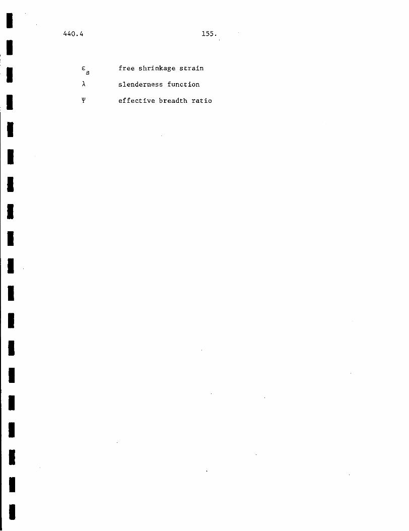
I I I I I I I I I I I I I I I I I I I
440.4
£ s
155.
free shrinkage strain
slenderness function
effective breadth ratio
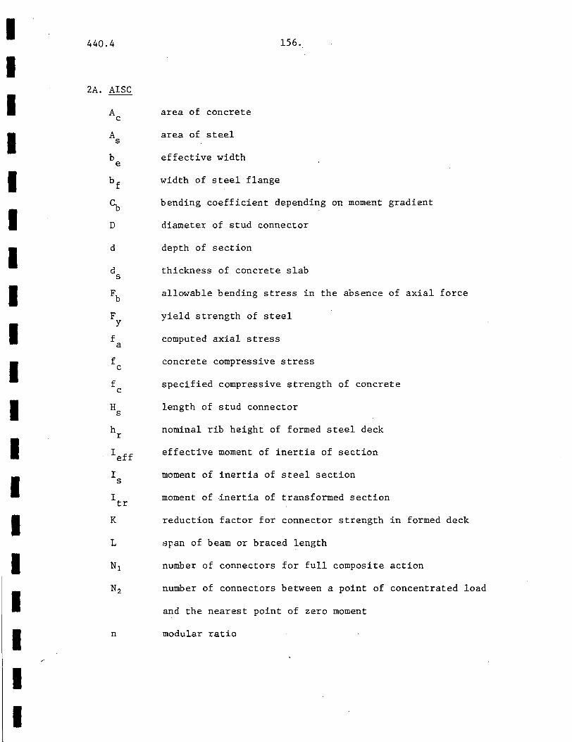
I I I I I I I I I I I I I I I I I I I
440.4
2A. AISC
A c
A s
b e
bf
cb
D
d
d s
Fb
F y
f a
f c
f c
H s
h r
Ieff
I s
I tr
K
L
Nl
N2
n
area of concrete
area of steel
effective width
width of steel flange
156.
bending coefficient depending on moment gradient
diameter of stud connector
depth of section
thickness of concrete slab
allowable bending stress in the absence of axial force
yield strength of steel
computed axial stress
concrete compressive stress
specified compressive strength of concrete
length of stud connector
nominal rib height of formed steel deck
effective moment of inertia of section
moment of inertia of steel section
moment of inertia of transformed section
reduction factor for connector strength in formed deck
span of beam or braced length
number of connectors for full composite action
number of connectors between a point of concentrated load
and the nearest point of zero moment
modular ratio
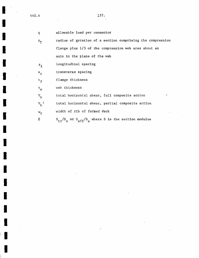
I I I I I I I I I I I I I I I I I I I
440.4
q
s.Q,
t w
157.
allowable load per connector
radius of gyration of a section comprising the compression
flange plus 1/3 of the compression web area about an
axis in the plane of the web
longitudinal spacing
transverse spacing
flange thickness
web thickness
Vh total horizontal shear, full composite action
v 1 h
8
total horizontal shear, partial composite action
width of rib of formed deck
S /S or S ff/S where S is the section modulus tr s e s
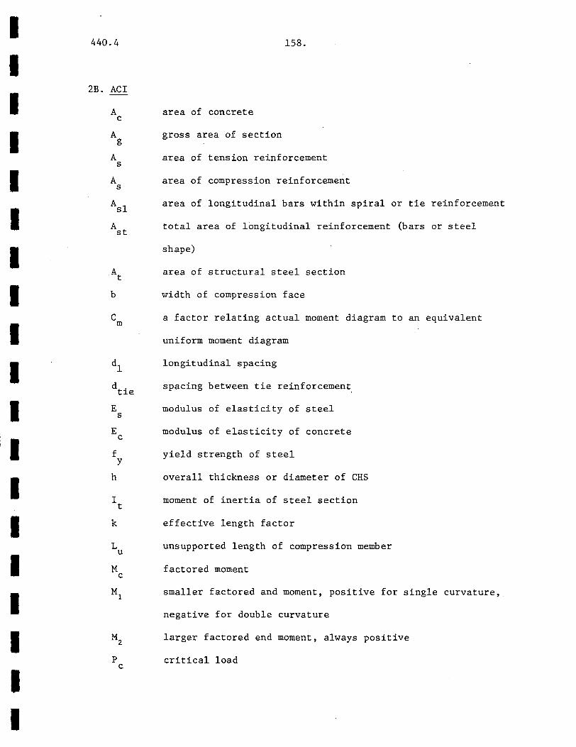
I I I I I I I I I I I I I I I I I I I
440.4 158.
2B. ACI
A c
A g
A s
A s
Asl
A st
b
c m
E s
E c
f y
h
area of concrete
gross area of section
area of tension reinforcement
area of compression reinforcement
area of longitudinal bars within spiral or tie reinforcement
total area of longitudinal reinforcement (bars or steel
shape)
area of structural steel section
width of compression face
a factor relating actual moment diagram to an equivalent
uniform moment diagram
longitudinal spacing
spacing between tie reinforcement
modulus of elasticity of steel
modulus of elasticity of concrete
yield strength of steel
overall thickness or diameter of CHS
moment of inertia of steel section
effective length factor
L unsupported length of compression member u
M c
factored moment
smaller factored and moment, positive for single curvature,
negative for double curvature
larger factored end moment, always positive
P critical load c
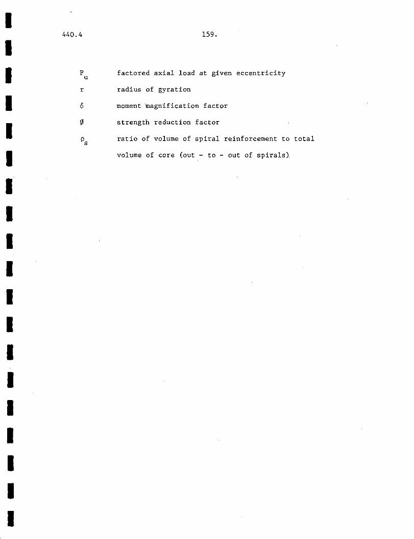
I I I I I I I I I I I I I I I I I I I
440.4
p u
r
159.
factored axial load at given eccentricity
radius of gyration
moment magnification factor
strength reduction factor
ratio of volume of spiral reinforcement to total
volume of core (out - to - out of spirals)
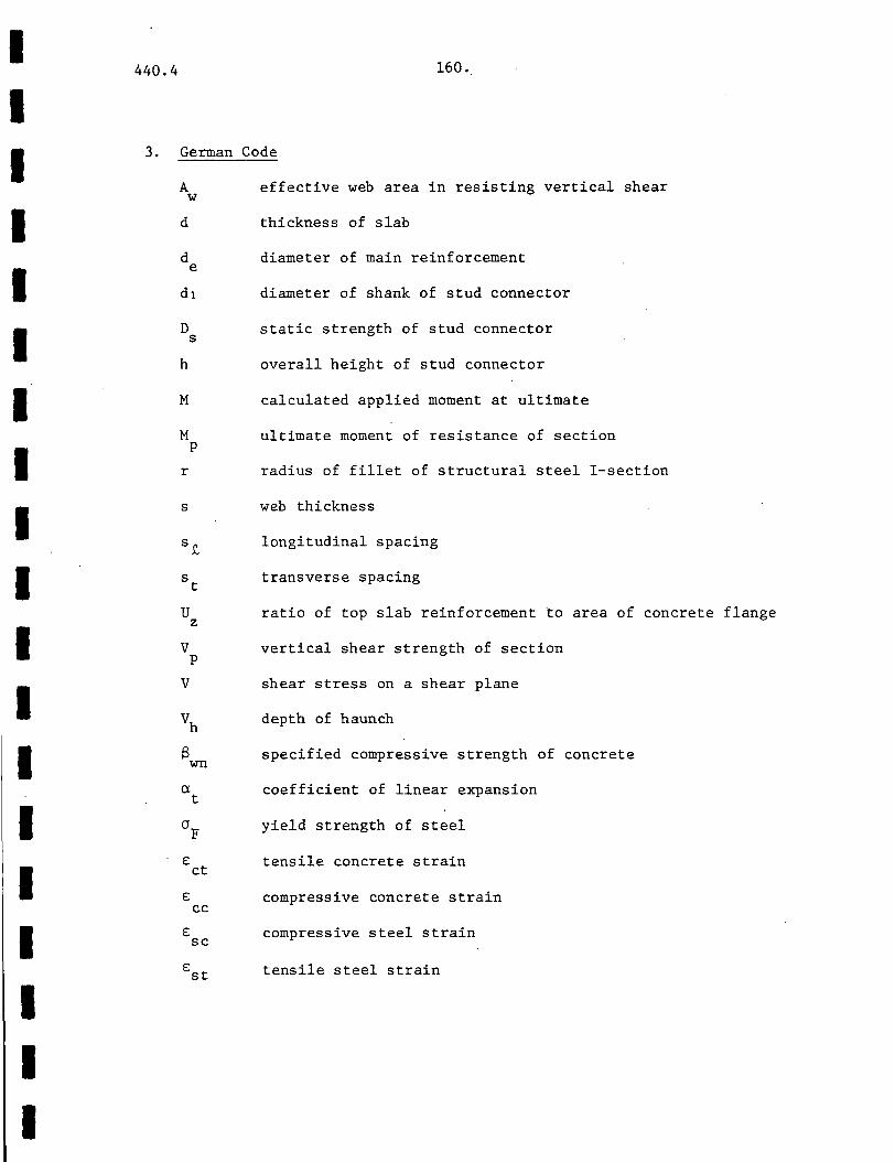
I 440.4
I I 3.
I I I I I I I I
I I I I I I
160 ..
German Code
A effective web area in resisting vertical shear w
d
d e
D s
h
M
M p
r
s
s~
v p
v
€ ct
€ cc
€ sc
thickness of slab
diameter of main reinforcement
diameter of shank of stud connector
static strength of stud connector
overall height of stud connector
calculated applied moment at ultimate
ultimate moment of resistance of section
radius of fillet of structural steel I-section
web thickness
longitudinal spacing
transverse spacing
ratio of top slab reinforcement to area of concrete flange
vertical shear strength of section
shear stress on a shear plane
depth of haunch
specified compressive strength of concrete
coefficient of linear expansion
yield strength of steel
tensile concrete strain
compressive concrete strain
compressive steel strain
Est tensile steel strain

I I I I I I I I I I I I I I I I I I I
440.4 161.
4 . MONOGRAPH.
A area of concrete c
A r
A s
b
D
D s
d
area of reinforcing bars
area of structural steel
width of section
design force for end anchorage
diameter of stud connector
depth of sction
E modulus of elasticity of concrete c
E s
H s
modulus of elasticity of steel
area of formed steel deck for calculating design force
for end anchorage
height of stud connector
h average flange thickness of channel connector c
I c
I r
I s
m
N
Q
moment of inertia of concrete section
moment of inertia of reinforcing bars
moment of inertia of steel section
moment of inertia of composite section
a constant for evaluating shear bond strength of formed
steel deck
shear span
as for k
number of loading cycles
shear force on a section
statical moment of composite section
stress range

I I I I I I I I I I I I I I I I I I I
440.4
t c
v u
w c
z
cr s
162.
web thickness of channel connector
ultimate shear strength
length of channel connector
design force for end anchorage design
a magnification foactor for axial load
yield strength of steel
strength of concrete
yield strength of reinforcing bars
slenderness function
I I I I I I I I I I I I I I I I I I I
440.4 163.
5. REFERENCES
1. ACI, 1977 BUILDING CODE REQUIREMENTS FOR REINFORCED CONCRETE (ACI 318-77),
American Concrete Institute, Detroit, Michigan.
2. ACI, 1977 COMMENTARY ON BUILDING CODE REQUIREMENTS FOR REINFORCED
CONCRETE (ACI 318-77), American Concrete Institute, Detroit, Michigan.
3. AISC, 1978 SPECIFICATION FOR THE DESIGN, FABRICATION ANY ERECTION OF
STRUCTURAL STEEL FOR BUILDINGS, American Institute of Steel Construction, New York.
4. AISC, 1973 MANUAL OF STEEL CONSTRUCTION, 7th Ed., American Institute of
Steel Construction, New York.
5. BISF, 1966 STEEL DESIGNERS' MANUAL, British Iron and Steel Federation,
London.
6. BSI, 1978 BS5400: PART 5 THE DESIGN OF COMPOSITE BRIDGES, British
Standards Institution, London.
7. BSI, 1972 CPllO THE STRUCTURAL USE OF CONCRETE, British Standards
Institution, London.
8. C and CA, 1972 HANDBOOK ON THE UNIFIED CODE FOR STRUCTURAL CONCRETE (CPllO:
1972), Cement and Concrete Association, London.
9. Council on Tall Buildings, Committee A41, 1979 MIXED CONSTRUCTION, Chapter SB-9, Vol. SB of Monograph on
Planning and Design of Tall Buildings, ASCE, New York.
10. Gaylord, E.H. and Gaylord, C.N., 1972 DESIGN OF STEEL STRUCTURES, McGraw-Hill, New York.
11. Hansell, W. C., Galambos, T.V., Ravindra, M. K. and Viest, I. M., 1978
COMPOSITE BEAM CRITERIA IN LRFD, Journal of the Structural Division, ASCE, Vol. 104, No. ST9, September 1978.
I I I I I I I I I I I I I I I I I I I
440.4 164.
12. Johnson, R. P., 1975 COMPOSITE STRUCTURES OF.STEEL AND CONCRETE, VOLUME 1, BEAMS,
COLUMNS, FRAMES AND APPLICATIONS IN BUILDINGS, John Wiley and Sons, New York.
13. Johnson, R. P., 1979 LIMIT STATE DESIGN OF COMPOSITE BRIDGES, Developments in
Composite and Mixed Construction, Lu, L. W. and Kato, B., Eds., Gyho-Do Publishing Co., Tokyo.
14. Lu, L. W., Slutter, R. G. and Yen, B. T., 1979 RESEARCH ON COMPOSITE STRUCTURES FOR BUILDING AND BRIDGE
APPLICATIONS, Developments in Composite and Mixed Construction, Lu, L. W. and Kato, B., Eds., Gyho-Do Publishing Co., Tokyo.
15. Marshall, W. T. and Nelson, H. M., 1974 STRUCTURES, Pitman, London.
16. Ogunronbi, P., Budkby, R. J. and Haensel, J., 1974 TRANSLATION OF THE GERMAN CODE OF PRACTICE FOR THE DESIGN
OF STEEL COMPOSITE BEAMS.
17. Ollgaard, J., Slutter, R. G. and Fisher, J. W., 1971 THE STRENGTH OF STUD SHEAR CONNECTORS IN LIGHTWEIGHT AND
NORMAL WEIGHT CONCRETE, AISC Engineering Journal, AISC, Vol. 8, No. 2, April 1971, pp. 55 - 64.
18. Slutter, R. G. and Driscoll, G. C., 1965 FLEXURAL STRENGTH OF STEEL-CONCRETE COMPOSITE BEAMS,
Journal of the Structural Division, ASCE, Vol. 91, No. ST2, Proc. Paper 4294, April 1965, pp. 77 - 99.
19. Subcommittee on State-of-the-Art Survey, Task Committee on Composite Construction, 1974
COMPOSITE STEEL-CONCRETE CONSTRUCTION, Journal of the Structural Division, ASCE, Vol. 100, No. STS, May 1974, pp. 1085 - 1139.
20. Tall, L., Ed., 1974 STRUCTURAL STEEL DESIGN, 2nd Ed., Ronald Press, John Wiley,
New York.
I I I I I I I I I I I I I I I I I. I I
440.4 165.
6. ACKNOWLEDGEMENTS
The assistance of Professor Lynn S. Beedle, Director of Fritz
Engineering Laboratory, and Professor Le-Wu Lu, my academic super
visor, is gratefully acknowledged. Professor Lu supplied me with
the necessary codes, without which this report would be impossible,
and also numerous research papers and useful references. Professors
Beedle and Lu have also kindly seen to the financial means to
produce the report, for which I extend my thanks to them.
My heartfelt gratitude and appreciation also go to my fiancee,
Lanie Y. H. Wong, whose constant and loving support has helped me
very much in my work. Her encouragement has been wonderful.
I express my thanks too to Kathryn Skaar who typed the manu
script. The manuscript by its nature is a difficult one but she
typed it patiently and skillfully. Mr. Donald W. Silfee, my good
friend, has also aided me greatly by drawing many of the figures and
diagram. Finally, to all who helped, I thank them.