composite overwrapped pressure vessels (copv)
TRANSCRIPT

NASA/SP–2011–573
Composite Overwrapped Pressure Vessels, A Primer Pat B. McLaughlan, P.E. Scott C. Forth, Ph.D. Johnson Space Center, Houston, Texas Lorie R. Grimes-Ledesma, Ph.D. Technical Review Jet Propulsion Laboratory, Pasadena, Calif.
March 2011
National Aeronautics and Space Administration Johnson Space Center Houston, TX 77058

NASA STI PROGRAM ... IN PROFILE
Since its founding, NASA has been dedicated to the advancement of aeronautics and space science. The NASA Scientific and Technical Information (STI) Program Office plays a key part in helping NASA maintain this important role. The NASA STI Program Office is operated by Langley Research Center, the lead center for NASA’s scientific and technical information. The NASA STI Program Office provides access to the NASA STI Database, the largest collection of aeronautical and space science STI in the world. The Program Office is also NASA’s institutional mechanism for disseminating the results of its research and development activities. These results are published by NASA in the NASA STI Report Series, which includes the following report types: • TECHNICAL PUBLICATION. Reports of
completed research or a major significant phase of research that present the results of NASA programs and include extensive data or theoretical analysis. Includes compilations of significant scientific and technical data and information deemed to be of continuing reference value. NASA’s counterpart of peer-reviewed formal professional papers but has less stringent limitations on manuscript length and extent of graphic presentations.
• TECHNICAL MEMORANDUM. Scientific
and technical findings that are preliminary or of specialized interest, e.g., quick release reports, working papers, and bibliographies that contain minimal annotation. Does not contain extensive analysis.
• CONTRACTOR REPORT. Scientific and
technical findings by NASA-sponsored contractors and grantees.
• CONFERENCE PUBLICATION. Collected papers from scientific and technical conferences, symposia, seminars, or other meetings sponsored or cosponsored by NASA.
• SPECIAL PUBLICATION. Scientific,
technical, or historical information from NASA programs, projects, and mission, often concerned with subjects having substantial public interest.
• TECHNICAL TRANSLATION. English-
language translations of foreign scientific and technical material pertinent to NASA’s mission.
Specialized services that complement the STI Program Office’s diverse offerings include creating custom thesauri, building customized databases, organizing and publishing research results . . . even providing videos. For more information about the NASA STI Program Office, see the following: • Access the NASA STI Program Home Page
at http://www.sti.nasa.gov • E-mail your question via the internet to
[email protected] • Fax your question to the NASA Access Help
Desk at (301) 621-0134 • Telephone the NASA Access Help Desk at
(301) 621-0390 • Write to: NASA Access Help Desk NASA Center for AeroSpace
Information 7121 Standard Hanover, MD 21076-1320
NASA/SP–2011–573
Composite Overwrapped Pressure Vessels, A Primer Pat B. McLaughlan, P.E. Scott C. Forth, PhD Johnson Space Center, Houston, Texas Lorie Grimes-Ledesma, Ph.D. Technical Reviewer Jet Propulsion Laboratory, Pasadena, Calif.
March 2011
National Aeronautics and Space Administration Johnson Space Center Houston, TX 77058

Available from:
NASA Center for AeroSpace Information National Technical Information Service 7115 Standard Drive 5285 Port Royal Road Hanover, MD 21076-1320 Springfield, VA 22161 Phone: 301-621-0390 or 703-605-6000 Fax: 301-621-0134
This report is also available in electronic form at http://ston.jsc.nasa.gov/collections/TRS/

iii
Contents Introduction ............................................................................................................................... 1 Overview ................................................................................................................................... 2 History of composite overwrapped pressure vessel development ............................................ 3 Current design experience ......................................................................................................... 4 Manufacturing ........................................................................................................................... 5 Inspection .................................................................................................................................. 5 Performance database ............................................................................................................... 6 Standardization of composite material for multiple composite overwrapped
pressure vessels ................................................................................................................. 7 COPV Failure Modes ................................................................................................................ 8 COPV Stress Rupture Discussion ............................................................................................. 8 Recommendations ..................................................................................................................... 9 Conclusion ................................................................................................................................ 10
Figures 1 COPV failure modes ........................................................................................................ 11 2 Kevlar®-epoxy (K/Ep) COPVs on shuttle ....................................................................... 12 3 Carbon fiber COPV, 6×16 in. .......................................................................................... 13 4 Typical carbon fiber COPVs ............................................................................................ 13 5 Fabrication of filament wound pressure vessels with hoop and helical layers ................ 14 6 Plastic-lined stress rupture test vessel .............................................................................. 15 7 Stress rupture testing and a hydraulic failure ................................................................... 16 8 Hydraulic burst of a COPV .............................................................................................. 17 9 Pneumatic burst of a COPV ............................................................................................. 17 10 Automotive application failure in Malaysia .................................................................... 18 11 Carbon strands probability of failure ............................................................................... 19 12 Kevlar® COPVs stress vs. probability of time to failure (for probability concept illustration only) ........................................................................ 20

iv
Acronyms COPV composite overwrapped pressure vessel DOT Department of Transportation ISS International Space Station LBB leak-before-burst NDE nondestructive evaluation NESC NASA Engineering and Safety Center psi pounds per square inch RFP request for proposal

1
Introduction Due to the extensive amount of detailed information that has been published on composite overwrapped pressure vessels (COPVs), this document has been written to serve as a primer for those who desire an elementary knowledge of COPVs and the factors affecting composite safety. In this application, the word “composite” simply refers to a matrix of continuous fibers contained within a resin and wrapped over a pressure barrier (as in string over a ball) to form a vessel for gas or liquid containment. COPVs are currently used at NASA to contain high-pressure fluids in propulsion, science experiments and life support applications. These COPVs have a significant weight advantage over all-metal vessels; but, as compared to all-metal vessels, COPVs require unique design, manufacturing, and test requirements. The most significant difference from metal designs is that COPVs involve a much more complex mechanical understanding due to the interplay between the composite overwrap and the inner liner. A metallic liner is typically used in a COPV as a fluid permeation barrier. The liner design concepts and requirements have been borrowed from all-metal vessels. However, the application of metallic vessel design standards to a very thin liner, and especially the composite, is not straightforward. Different failure modes exist for COPVs than for all-metal vessels, and the understanding of these failure modes is at a much more rudimentary level than for metal vessels. Three significant differences exist between composite and metal vessels:
1) While composites of carbon, Kevlar®, and glass are subject to a reduction in burst strength as a result of surface impact, Kevlar® and glass are more damage tolerant than carbon. Metallic and Kevlar® overwrapped vessels, which were used extensively in the Space Shuttle program, do not lose significant structural strength due to minor surface damage. Handling personnel at launch facilities, COPV designers, and the crew have needed to be educated on the risks of damaging a COPV.
2) Composites are subjected to an effect that is referred to as stress rupture or static fatigue in which, depending on multiple factors, a composite may fail as a function of time while it is at operating pressure. The likelihood of such a failure is remote if the failure potential is properly addressed in design and test.
3) Quantitative nondestructive testing methods used for flaw screening of thick-walled metallic structure are generally not applicable to COPV designs.
Pressure vessels have historically been classified as failing due to either burst or leak-before-burst (LBB). These designations have been misleading in the past, suggesting that a vessel that is designated as LBB does not require further monitoring or vigilance. However, it is not recognized that the pressure vessel failure modes must be addressed during all phases (design, qualification, and use) to ensure safety. Because of the additional composite failure modes for COPVs, deter-mination of appropriate ways to address failure modes is usually more complex than for metal-lic vessels. The ability to, with certainty, predict a specific failure mode is difficult due to the interaction between the liner and the composite. However, COPVs are safely used in a wide range of applications, from natural gas vehicles to military rockets. Generally, it is only in ultra-
2
lightweight designs for space flight, where there is little margin on strength, that all of the COPV failure modes are credible and must be clearly addressed in design and operation.
Overview A composite, as defined in this COPV application, is a combination of structural fibers and a resin that forms the overwrapped structure for a COPV. Continuous fibers provide tensile strength for structural integrity while the resin carries shear loads in the composite and maintains the fiber position. As the fiber/resin composite is generally not considered pressure tight, the composite is applied over a fluid-retention barrier that serves as an interior liner for the composite. These fluid-retention barriers may be a rubber, plastic, or thin ductile metal liner. These liners serve to maintain acceptable leak rates and fluid purity but add little, if any, structural integrity. Development is currently under way for the use of no liners or of extremely thin liners in future COPVs. On most ISS and Shuttle COPVs, the vessel liner is substantial and serves as a partial structural element by carrying a portion of the pressure load. The rigid metal liner also serves as a mandrel on which the fiber/wet resin is wrapped to form the composite structure. A vessel that contains a structurally significant liner in which the liner and the composite share in resisting the internal pressure load is said to have a load-sharing liner. Both metal vessels and COPVs offer unique advantages. An assessment based on their performance needs and application is required to define the optimal design approach. Both types of construction range from vessels of large burst pressure safety factors for industrial and commercial applications to high-efficiency (efficiency is the ratio of product capacity to vessel weight) vessels for rocket and spacecraft applications. For lightweight, high-efficiency applications, the COPV will offer a significant weight advantage, approximately one-half the weight of a comparable metal tank. The all-metal vessel, while possibly heavier, usually offers the advantage of lower manufacturing cost, verification of fracture control by analysis, and simply a more straightforward design. Demonstrating fracture control requirements for a COPV, such as safe life and/or LBB of the thin metallic liner and damage tolerance of the composite overwrap, is usually verified by costly qualification tests. Well-established nondestructive evaluation (NDE) methods are in use for thick metallic structures that are used to quantitatively establish a critical flaw size that is screened for during acceptance testing. The nondestructive inspection is used in the safe-life and LBB analyses as a starting point for predicting life or vessel failure. These NDE methods have not been quantitatively demonstrated for thin metallic liners or composite materials. Work in this area is ongoing and significant progress has been made in composite NDE technology as of this writing. Proof testing is an excellent screening tool for manufacturing anomalies, but may not effectively screen a vessel that is susceptible to fatigue cracking in the liner or a premature stress rupture failure in the composite. High-efficiency COPVs have been very effectively and safely used in single-use, crewless launch vehicles for space applications. It is always important for a designer to remember that each application of a pressure vessel should have a mass, performance, cost and risk trade.

3
History of composite overwrapped pressure vessel development In the early 1970s, the primary author was assigned to a technology transfer task that focused on improving respiratory protection for municipal firefighters – a task that eventually led to the widespread commercialization of COPVs. The NASA Firefighter’s Breathing System Program that arose from this assignment quickly evolved into a significant technology effort involving cooperation between NASA and multiple fire service organizations across the United States, including those in Boston, Los Angeles, and New York City. After a requirements definition phase, several trade studies were conducted to address the major concerns of firefighters regarding respiratory protection. Drawing on results of these trade studies, researchers determined that a reduced weight and bulk compressed-air breathing system was optimum. In this type of system, the greatest contributor to weight and bulk is the compressed-air pressure vessel. The breathing system that was commonly employed in the 1970s used compressed-air vessels of conventional steel or aluminum design. While these vessels met appropriate Department of Transportation (DOT) requirements (operating at 2,200 pounds per square inch [psi] pressure), these requirements were not optimum for a reduction in physical dimensions. To achieve a reduction in the bulk of the improved system, air storage pressure was increased to 4,500 psi. Other performance parameters, such as a weight reduction, were also sub-sequently defined, and a request for proposal (RFP) was released by NASA to industry to design, test, and manufacture a lightweight and higher-pressure compressed air vessel. The primary objective of this RFP was to reduce pressure vessel weight while maintaining required firefighter breathing air quantity. Secondary objectives included: durability, low production costs, minimum maintenance, and a potential for future high-volume commercial production. Various high-strength alloy steel vessels were proposed by current suppliers in addition to two proposals for glass composite overwrapped vessels. Both composite vessel pro-posals projected rugged vessels of one-half the weight of the existing metal vessels and, most importantly, a desire to enter commercial production to satisfy future firefighter demand. As part of the NASA Firefighter’s Breathing System Program, additional improvements were made in system pressure regulators, face masks, end-of-duration warning, and human factors. The resulting NASA Firefighter’s Breathing System concept was accepted by the fire service, which led to a demand for commercial production of the lighter COPVs. The composite vessels received certification from the DOT in 1975, and commercial production was initiated. Although the DOT-certified vessels are designed to a greater factor of safety on burst pressure than is currently used in some COPV military and aerospace application, a 50% pressure vessel weight reduction over the metal design was nevertheless achieved. As production of the COPVs has continued, fiber technology has evolved from glass to Kevlar® to carbon composites. This evolution of higher-strength fibers has led to further weight reductions. Hundreds of thousands of composite vessels for commercial applications are now produced per year, and these are used worldwide. The safety record of COPVs in commercial service has proven exceptional. To some extent, the success in the early 1970s of these firefighter COPVs may have bolstered the use of Kevlar® COPVs for storage of the large quantities of high-pressure helium and nitrogen
4
on the space shuttle orbiter. At this time, metal vessel design and test standards dominated, rather than new standards, to support COPV performance characteristics. During the devel-opment of the orbiter COPVs, the primary design emphasis was on a load-sharing metal liner with less concentration on the overwrap, which was the primary structural element. The orbiter COPV used cylindrical or spherical metal liners that served to share load with the composite, retain the gaseous pressurant, and provide a mandrel or form on which to wrap the resin-coated Kevlar® fiber. Analysis and test emphasis of the orbiter vessels appeared to be on the perform-ance of the metal liner while the wrap was considered only a highly reliable agent with which to supplement metal liner performance. Owing to our lack of composite experience in the late 1970s, the Space Shuttle Orbiter COPVs were produced and tested to a procurement and certification standard better suited for all-metal vessels. As the responsible technical team had extensive experience in metal vessels, team mem-ber emphasis was on the metal liner rather than a system-approach integrating liner and composite performance. The factor-of-safety margins, development testing, burst test articles, manufacturing inspections, and acceptance procedures did not fully address the unique, and generally unknown, composite characteristics. For example, determination of fiber stress at operating pressure and burst pressure may have been clouded by a limited understanding of the load-sharing relationship between the metal liner and the overwrap. The expected range of time to stress rupture failure dominated all subsequent assessments of the space shuttle orbiter COPV performance. Stress rupture was the dominant concern because all other COPV failure modes had been adequately addressed during development and qualification testing. A stress rupture failure would, in all probability, be catastrophic – potentially resulting in loss of a processing facility, a space flight vehicle, and life. This, therefore, is a serious con-sideration, particularly in light of the fact that no method existed for predicting an impending failure. Fortunately, recent analysis and test has indicated acceptable reliability.
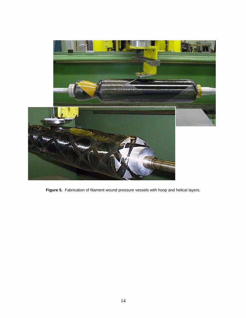
Current design experience The COPV design requires an analysis of the liner, the fiber overwrap, and the interaction between the two. COPV liners may be of ductile materials, such as soft aluminum, with only minimal load-sharing capabilities. Higher-strength steel, Inconel®, titanium, or cryogenically formed stainless steel may alternatively be used, resulting in a load-sharing liner. Recent projects have begun using plastic-lined COPVs to minimize weight. The fiber is generally applied as a ribbon of multiple fibers that passes through a bath for resin application. This ribbon of fiber and resin is wound on the liner as one would wind a ball of string. The pressure vessel liner and the dispensing head for the fibers ribbon move in relation to one another in such a way as to wrap the fiber on the liner in a desired pattern. If the vessel is cylindrical rather than spherical, fiber winding is normally applied in both a longitudinal (helical) and a circumferential (hoop) wrap. This winding process consists of multiple critical steps, such as resin content, fiber configuration, winding tension, and the pattern of the wrap in relation to the axis of the liner. The resin is then allowed to cure (dry and harden) at an elevated temperature. Following post-cure inspections, the vessel may be sized, or autofretaged, to improve structural performance. Autofretage is a process whereby a COPV is pressurized to above the liner yield

5
strength, causing the liner to plastically deform or expand. The liner is now permanently expanded so that, at the time of depressurization, a tensile strain (or stress) remains in the fiber composite due to the enlarged liner and a compressive strain is induced in the liner. A measurement of the ex-pansion in internal volume is desirable to quantify the amount of residual strain in both the liner and the overwrap. The compressive residual strain in the liner results in an improved cycle life performance of the liner. The sizing (or autofretage) of the wrapped liner may serve as a proof test, or a second proof (at a lower pressure) may be accomplished.
Manufacturing Manufacturing process certification is key to reliable composite performance. Process control and consistency are mandatory when minimizing performance variability. This is because limited testing will not fully define the range of performance variability expected in burst pressure or the time to stress rupture failure. Composite variability may, therefore, present serious safety issues. Of course, any structure has some level of variability that is compensated for by design margins; but, for composites, the extreme performance variability that has been experienced, coupled with the potentially catastrophic nature of failure, demands consistency in manufacturing. Fibers may experience variability in ultimate strength and time to stress rupture between production batches. This inconsistency in fiber performance may be rooted in the variability in chemical composition, processing, and fiber diameter. Effective sampling and verification of fiber characteristics at the time of acceptance is mandatory. Performance consistency of the com-pleted COPV requires mandatory consistency in the materials of composite fabrication (e.g., the fiber spools and resin). It is thus important that COPV materials manufacturing and inspection practices be controlled to limit performance variability and the possibility of unexpected catastrophic failure. Prior COPV testing has indicated significant difference in stress rupture performance as a function of the different spools of fiber delivered by some fiber manufacturers. Therefore, the burst and time to stress rupture variability issue may not rest entirely with the COPV manufacturing process or design, but with the supplier of the fibers. To formulate an acceptable understanding of final product performance characteristics, rigorous standards and material acceptance testing must be in place from raw materials through the finished product. The production of COPVs also involves fabrication of a cylindrical or spherical metal liner . This metal liner serves multiple functions: as a pressure-tight fluid seal, a form, or a mandrel on which to wrap the fiber/resin composite and, possibly, as a load-carrying structural element. As an integral part of the COPV, the liner must satisfy appropriate NDE inspections prior to application of the overwrap.
Inspection Although several inspection techniques are currently in place for COPVs, unfortunately none of them provides the level of confidence that metal vessel inspection offers. Metal vessels may be subject to well-established tests to:
1) Determine material properties prior to fabrication.

6
2) Provide NDE inspection of the completed vessels screen for cracks, porosity, partial thickness welds, and other defects.
3) Determine localized stresses by strain gauges or other measurement systems. 4) Achieve structural verification of the completed product through over-pressurization tests.
For COPVs at this time, NDE, as an indicator of future performance, is not a viable inspection method to use when effectively verifying the composite. In fact, composite inspection lacks the definitive results that we rely on in metal inspection. Proof testing, as previously mentioned, may be an effective screen for defects; but a satisfactory proof test is not considered a predictor of future performance since it does not address stress rupture. Field-use damage from impact and potentially harmful environmental exposure will also affect COPV performance. Damage-tolerance testing of the composite overwrap has demonstrated that certain tank designs can be very sensitive to impact. Recent COPV designs have improved the damage tolerance by including sacrificial outer layers and affording more material to the dome-transition region, where early COPV designs were overly sensitive to small amounts of damage. Trained inspectors, well-defined protection schemes, and knowledgeable engineering support are critical to maintaining the safe use of COPVs.
Performance database In some ways, composite vessel design and manufacturing may still be considered more an art than a science. Today’s COPVs – which are used in commercial applications such as firefighter breathing system air cylinders, vehicle compressed-gas fuel storage, and commercial aircraft applications (e.g., escape slide nitrogen pressurization system and emergency cabin breathing oxygen) – are very widespread and available worldwide. These COPVs have large safety margins and are approved by DOT regulations. Other reduced-weight, non-DOT-approved COPVs may operate at smaller safety margins; these include gas storage COPVs for space launch vehicles, satellites, and spacecraft; military aircraft; and military weapons systems. Whether a COPV is intended for use commercially or in space flight, it is vital to be able to establish appropriate confidence in its reliability and safety. As previously mentioned, COPVs may, in the event of composite failure, experience a catastrophic explosive release of energy due to the high pressure of the stored gas. Although the possibility of failure is remote, the potential consequences of such a failure, especially in a human space flight application, mandates a high level of design reliability. Reliability analysis must therefore be based on a significant composite performance database of like composite materials that are in like configurations. This database should provide performance data that include: ultimate strength, time to stress rupture failure as a function of fiber stress, and the effect of temperature on time to stress rupture failure at various stress levels. Typical methods for data accumulation include:
1) Ultimate strength of individual fibers 2) Strands, which are a small bundle of fiber and resin formed as a composite longitudinal
element, that may be loaded in tension to test for ultimate strength or stress rupture 3) A subscale test sphere or cylinder, which may contain a ductile or load-sharing liner 4) Full-size COPVs in the end-use configuration

7
Testing of full-size COPVs provides the ability to assess actual performance of the specific fiber wrap configuration without the unknown of interpretation from material coupon data, such as strands, or subscale units. Some data have indicated a reduced average ultimate strength in larger, as compared to smaller, COPVs. Whether this is due to a thicker composite, more material being used in the application, winding pattern differences, or longer fibers has not yet been quantified. The longer fibers required to circle a larger vessel may relate to the theory that a long rope is not as strong as a short rope due to the potential for a greater number of flaws in the longer rope. The size effect has to be modeled using the Weibull Strength Theory, which has indicated a reduction in the ultimate strength of the thicker composite on larger COPVs. The most important data point is to determine whether the stress rupture performance of the full-size article falls within the expected database established by the subscale test articles. Due to the very long time required to demonstrate stress rupture in normal design conditions, it will be necessary to accelerate the time to stress rupture by increasing the stress in the composite through higher pressure and by elevating temperatures that may accelerate the time to stress rupture.
Standardization of composite material for multiple composite overwrapped pressure vessels If multiple COPVs of alternate configurations will be used within a given program, it is highly desirable to test a single fiber and resin composite to establish a material performance baseline from a large quantity of subscale test articles. Commonality in fiber, resin, and processing char-acteristics will aid in establishing a very early-in-program development material performance baseline for full-size articles of multiple configurations and applications. Other composite performance variables, such as wrap thickness, winding patterns, and vessel size, must be specifically evaluated. Appropriate certification of the flight system reliability of a COPV presents challenges that are not normally encountered in conventional all-metal vessels. Metal vessels are constructed of well-defined materials designed to mature standards, and are inspected by a means that allows specific identification of deficiencies in a specific vessel. As compared to metals technology, composites technology presents challenges in the raw material variability, manufacturing consistency, and design verification process. Certification testing is a requirement that must strictly apply not only to the design, but also to the consistency of materials and manufacturing. Prior to beginning a certification process, an early and extensive development test must be per-formed to define the characteristics of selected fibers and resins and manufacturing processes. A very early start of this development testing process is mandatory due to the effect damage tolerance and stress rupture considerations can have on the vessel design; e.g., exterior helical wraps have been shown in some designs to be more damage-tolerant than exterior hoop wraps. If a COPV is required to withstand a specific impact energy level to meet damage-tolerance requirements, this must be incorporated into the design, usually resulting in a thicker overwrap. Further, to understand the probability of a stress rupture failure, data must exist for a period of calendar time that exceeds the use time for both the specific composite structures material and the vessel configuration.

8
COPV Failure Modes The NASA Johnson Space Center Fracture Control Board Chairman and coauthor, Scott Forth, Ph.D., has identified the following four COPV failure modes for control in hazard reports:
1) Burst from Over-pressurization. The unexpected burst of a COPV from over-pressurization is mitigated by material certification, designing to conservative material allowable, and proof-pressurization of the vessel during acceptance testing. The external pressurization source must also be controlled to prevent accidental excessive pressurization.
2) Fatigue Failure of the Metallic Liner. Fatigue failure of the metallic liner is mitigated by inspection and testing. Nondestructive inspection of the liner at manufacture ensures that critical flaw sizes are adequately screened. The COPV design may then be pressurization-cycle-tested during qualification to a factor significantly greater than the design life to ensure an adequate margin on design cycle life.
3) Burst Resulting from Metallic Liner or Composite Damage. Failure of the composite is mitigated by appropriate protection from damage and damage-tolerance testing. Visual inspection may be valuable in identifying surface damage, although subsurface damage to the composite or liner may not be easily identifiable.
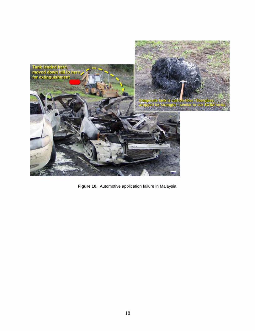
4) Stress Rupture of the Composite Overwrap. Fiber-wrapped composite vessels differ from metal vessels in that they experience an effect known as stress rupture, or static fatigue. Stress rupture is a situation in which the composite experiences degradation, as a function of time. This degradation results in a sudden structural failure of the pressurized vessel’s composite overwrap, resulting in the rapid release of the vessel’s contents and the stored energy of the pressurized gas – possibly causing serious injury and damage to the surroundings.
COPV Stress Rupture Discussion Dr. Leigh Phoenix of Cornell University provided the following definition of COPV stress rupture (failure mode number 4) above:
“Stress rupture is a sudden failure mode for [COPVs] that can occur at normal operating pressures and temperatures. This failure mode can occur while at stress levels below ultimate strength for [an] extended time. The failure mechanism is com-plex, not well understood, [and] difficult to accurately predict or detect prior to failure. The location and mechanism of triggering damage causing sudden failure is highly localized, but at a random location. This location and extent of local damage has not been able to be [reliably] detected by current [NDE] techniques prior to catastrophic failure. Pressure, duration of time at pressure, and temperature experienced contribute to the degradation of the fiber and/or the fiber-matrix interface, particularly around accumulations of fiber breaks, and these increase the probability of COPV stress rupture.”
To date, the composite stress rupture failure mode may not be fully understood, although conservative design and thorough testing can produce highly reliable COPVs. To date, there have been zero stress rupture failures of COPVs in NASA spaceflight applications. However, stress rupture failures have been observed in accelerated test programs at NASA JSC for both

9
Kevlar® and carbon overwrapped COPVs. For Kevlar® COPVs, the manufacturer can compute the stress rupture reliability using a Weibull model because a large, robust database exists. Un-fortunately, as of the writing of this paper, there is not a similar database for carbon. Two NASA independent stress rupture test programs are currently under way that should provide additional data availability in 2013 for analysis. Until that time, the NESC and JSC Engineering recommend that the carbon fiber strain remain at or below 50% of the ultimate strength. Based on industry-wide experience, the risk of stress rupture at a strain ratio of 50% is minimal for short-duration space missions. Due to the unknowns relating to stress rupture variability in composite performance and a lack of well-defined inspection methods, the COPV factors of safety (or design safety margins) may be addressed differently than those applied to all-metal vessels. In other words, the COPV factor of safety may be higher to compensate for unknown variability. Factors of safety may also be adjusted for usage conditions. The application of COPVs may range from single-pressurization, remote military uses to long-term, public applications involving many pressurization cycles. The design and factor of safety must be adjusted for the application.
Recommendations The following are recommendations for development of COPVs in both commercial and space flight applications.
1) Design the COPVs to satisfy their intended application. For example, a COPV used in a public application with an expected long lifetime and exposed to uncontrolled environ-ments as well as multiple pressure cycles will require more reliability margins, such as greater factors of safety and mitigation of environmental degradation, than a COPV that is intended for a single-use pressurization in orbital space flight or military applications.
2) Recognize that COPVs have significantly different characteristics than metal vessels and
require unique standards. Material and manufacturing controls, performance requirements, safety margins, useful life, and environmental restrictions all present requirements that differ from those applied to all-metal vessels. As a COPV is more complex than a metal vessel, failure modes unique to COPVs must be addressed. These include composite failure modes such as stress rupture and impact damage
3) Develop an extensive performance database for the specific composite system. The
generalized performance of glass and Kevlar® fibers and subscale COPVs are documented, but that of the class of fibers referred to as carbon (or possibly graphite) is not as well-documented. Carbon fiber characteristics, as applied to the raw material consistency, manufacturing processes, aging factors, ultimate strength and stress rupture variability, and other critical factors ensuring long-term reliability, must be well understood. This requires that material performance be evaluated in configurations such as individual fibers, compo-site strands (a linear structural element of fiber and resin), test rings, subscale COPVs, and ideally full-size vessels of each configuration. A time element exists in the degradation of fiber performance, and the full-size COPV configuration may include localized areas of higher stress sensitive to the effects of time at pressure and environmental conditions. Per-

10
formance correlation from subscale to full-scale testing may not be fully reliable; there therefore is a need for evaluation by extensive composite instrumentation/inspection meth-ods and possible accelerated (by elevated temperature/pressure) stress rupture testing.
4) Reduce complexity in materials testing by using a single or limited fiber/resin combination
for all vessel configurations in a given program. Some performance differences in the composite may remain due to size, composite thickness, and liner load share characteristics, but an extensive database for a specific fiber and resin combination is desirable.
5) Evaluate the selection of all-metal vessels vs. COPVs for a specific application. An all-
metal vessel may offer significant advantages in some applications while a COPV may be superior in other applications. The use of a COPV requires acceptance of the additional complexity of composite usage and treatment of composite failure modes in additional to metallic failure modes. While a catastrophic failure of a COPV that results in loss of property and life cannot be ruled out, the probability of such a failure occurring may be reduced to acceptable levels through appropriate design and test.
Conclusion Undoubtedly, the use of COPVs will be expanding as the demand for efficient storage of pressurized gases increases in a variety of commercial, aircraft, spacecraft, and transportation applications. Metal vessels have evolved from the time, well over a century ago, of exploding steam boilers to their mature and reliable technology today. Now COPV technology is continuing development to provide an increasing understanding of material characteristics and the resultant increasing COPV reliability. As this technology development continues, additional information will be available to aid in vessel material selection and design process to satisfy performance requirements for the intended application.

11
Courtesy of Lorie Grimes-Ledesma, Ph.D., NASA Jet Propulsion Laboratory, Pasadena, Calif.
Figure 1. COPV failure modes.
Failure Mode Failure Result Control Phase Mitigation Method
Shearing of Boss Catastrophic Design /NDE Statistical, NDI
Fatigue Crack Growth in Liner under Composite Leakage Design/NDE Fracture Control (Safe-Life)
Crack Growth in Boss Catastrophic Design/NDE Fracture Control (Safe-Life)
Over Pressurization Catastrophic System Design/Operations Thermal Control and System Design
Stress-Rupture Catastrophic Design/Operations Stress-Rupture Data
Corrosion/Stress-Corrosion of Liner under Composite Catastrophic Design/Mfg/Operations Control of Chemical Environment
Corrosion/Stress-Corrosion of Boss Catastrophic Design/Mfg/Operations Control of Chemical Environment
Embrittlement of Liner Catastrophic Mfg/Operations Metallurgical Control, Control of Thermal and Chemical Environments
Corrosion of Matrix Resin or Fiber Catastrophic Mfg/Operations Control of Chemical Environment
Embrittlement of Matrix Resin or Fiber Catastrophic Mfg/Operations Control of Cure, Control of Thermal and
Chemical Environments Liner Buckling under Composite/fatigue Leakage Mfg/NDE Adhesive Bonding Process Control,
Bond-Line NDE
Impact/Mechanical Damage Catastrophic Mfg/NDE/Operations Damage Control
Delamination (of mounting interface and bridging) Catastrophic Mfg NDE

12
Figure 2. Kevlar®-epoxy (K/Ep) COPVs on shuttle.
Kevlar® COPV Locations on the Shuttle Orbiter (blue arrows)• Six 26-in.N2 K/Ep COPVs shown in dark yellow• Eighteen 19 to 40-in. He K/Ep COPVs shown in lime green
13
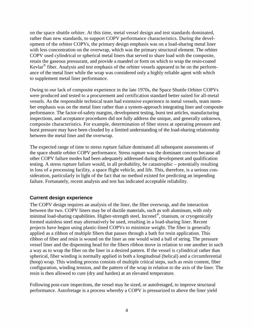
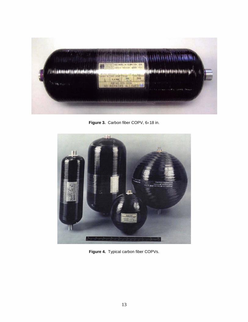
Figure 3. Carbon fiber COPV, 6×18 in.
Figure 4. Typical carbon fiber COPVs.
14
Figure 5. Fabrication of filament wound pressure vessels with hoop and helical layers.

15
Figure 6. Plastic-lined stress rupture test vessel.

16
Figure 7. Stress rupture testing and a hydraulic failure.

17
Figure 8. Hydraulic burst of a COPV.
Figure 9. Pneumatic burst of a COPV.
18
Figure 10. Automotive application failure in Malaysia.

19
Figure 11. Carbon strands probability of failure (for probability concept illustration only).
75% ofult. strength
70% ofult. strength
80% ofult. strength
0.9990.99
0.900.96
0.75
0.50
0.25
0.10
0.05
0.02
0.01
10-4 10-2 100 102 104
80% specimen first failure75% specimen first failure70% specimen first failure
Range of failure times, hours
Note: Carbon strand testterminated at 104 hours. Majorityof 50 specimensat 70% and 75%of ult. strength had not failed.
Prob
abili
ty o
f fai
lure

20
Figure 12. Kevlar® COPVs stress vs. probability of time to failure (for probability concept illustration only).
Com
post
ie s
tress
as
a %
of u
ltim
ate
stre
ss
1
0.95
0.9
0.85
0.8
0.75
0.7
0.65
0.6
0.55
0.5
0.45
0.4
Failure probability time, hours0.001 0.01 0.1 1 10 100 1,000 10,000 100,000 1,000,000
1 Day1 Year10 yrs25 yrsProbablilityof Failure0.50.010.0010.00010.000001Test vesselsmedian failureTest vesselsrange oftime to failure


REPORT DOCUMENTATION PAGE Form Approved OMB No. 0704-0188
Public reporting burden for this collection of information is estimated to average 1 hour per response, including the time for reviewing instructions, searching existing data sources, gathering and maintaining the data needed, and completing and reviewing the collection of information. Send comments regarding this burden estimate or any other aspect of this collection of information, including suggestions for reducing this burden, to Washington Headquarters Services, Directorate for Information Operations and Reports, 1215 Jefferson Davis Highway, Suite 1204, Arlington, VA 22202-4302, and to the Office of Management and Budget, Paperwork Reduction Project (0704-0188), Washington, DC 20503.
1. AGENCY USE ONLY (Leave Blank) 2. REPORT DATE 3. REPORT TYPE AND DATES COVERED March 2011 Special Publication
4. TITLE AND SUBTITLE
5. FUNDING NUMBERS Composite Overwrapped Pressure Vessels, A Primer
6. AUTHOR(S) Pat B. McLaughlan*, Scott C. Forth,* Lorie R. Grimes-Ledesma**
7. PERFORMING ORGANIZATION NAME(S) AND ADDRESS(ES) 8. PERFORMING ORGANIZATION REPORT NUMBERS
Lyndon B. Johnson Space Center Houston, Texas 77058
S-1046
9. SPONSORING/MONITORING AGENCY NAME(S) AND ADDRESS(ES) 10. SPONSORING/MONITORING AGENCY REPORT NUMBER
National Aeronautics and Space Administration Washington, DC 20546-0001
SP-2011-573
11. SUPPLEMENTARY NOTES *NASA Lyndon B. Johnson Space Center, **NASA Jet Propulsion Laboratory
12a. DISTRIBUTION/AVAILABILITY STATEMENT 12b. DISTRIBUTION CODE
Unclassified/Unlimited Available from the NASA Center for AeroSpace Information (CASI) 7115 Standard Hanover, MD 21076-1320 Category: 34
13. ABSTRACT (Maximum 200 words) Due to the extensive amount of detailed information that has been published on composite overwrapped pressure vessels (COPVs), this document has been written to serve as a primer for those who desire an elementary knowledge of COPVs and the factors affecting composite safety. In this application, the word “composite” simply refers to a matrix of continuous fibers contained within a resin and wrapped over a pressure barrier to form a vessel for gas or liquid containment. COPVs are currently used at NASA to contain high-pressure fluids in propulsion, science experiments, and life support applications. They have a significant weight advantage over all-metal vessels but require unique design, manufacturing, and test requirements. COPVs also involve a much more complex mechanical understanding due to the interplay between the composite overwrap and the inner liner. A metallic liner is typically used in a COPV as a fluid permeation barrier. The liner design concepts and requirements have been borrowed from all-metal vessels. However, application of metallic vessel design standards to a very thin liner is not straightforward. Different failure modes exist for COPVs than for all-metal vessels, and understanding of these failure modes is at a much more rudimentary level than for metal vessels.
14. SUBJECT TERMS 15. NUMBER OF PAGES
16. PRICE CODE
pressure vessels; propellant tank; pressure vessel design; shells (structural forms); rocket linings; lining processes; shielding 30
17. SECURITY CLASSIFICATION OF REPORT
18. SECURITY CLASSIFICATION OF THIS PAGE
19. SECURITY CLASSIFICATION OF ABSTRACT
20. LIMITATION OF ABSTRACT
Unclassified Unclassified Unclassified Unlimited Standard Form 298 (Rev Feb 89) (MS Word Mar 97) Prescribed by ANSI Std. 239-18 298-102
NSN 7540-01-280-5500

