component technical manual powertech® 2.9 l diesel …
TRANSCRIPT

PowerTech® 2.9 L Diesel Engines
CTM125 14JUN01 (English)
COMPONENT TECHNICAL MANUAL

Introduction
CD03523,00000DB –19–03JAN01–1/1
Foreword
This manual is written for an experienced technician.Essential tools required in performing certain servicework are identified in this manual and arerecommended for use.
Live with safety: Read the safety messages in theintroduction of this manual and the cautions presentedthroughout the text of the manual.
This is the safety-alert symbol. When you see thissymbol on the machine or in this manual, be alert tothe potential for personal injury.
Use this component technical manual in conjunctionwith the machine technical manual. An applicationlisting in the introduction identifiesproduct-model/component type-model relationship. Seethe machine technical manual for information oncomponent removal and installation, and gainingaccess to the components.
This manual is divided in three parts: repair, operationand tests, tools and specifications. Repair sectionscontain necessary instructions to repair thecomponent. Operation and tests sections help you
identify the majority of routine failures quickly. Toolsand specifications sections are summary listings of allapplicable essential tools, service equipment and tools,other materials needed to do the job, service parts kits,specifications, wear tolerances, and torque values
Information is organized in groups for the variouscomponents requiring service instruction.
Component Technical Manuals are concise serviceguides for specific components. Component technicalmanuals are written as stand-alone manuals coveringmultiple machine applications.
Fundamental service information is available fromother sources covering basic theory of operation,fundamentals of troubleshooting, general maintenance,and basic type of failures and their causes.
Read each block of material completely beforeperforming service to check for differences inprocedures or specifications. Follow only theprocedures that apply to the engine model number youare working on. If only one procedure is given, thatprocedure applies to all the engines in the manual.
CALIFORNIA PROPOSITION 65 WARNINGDiesel engine exhaust and some of its constituents are known to the State
of California to cause cancer, birth defects and other reproductive harm.
CTM125 (14JUN01) POWERTECH 2.9 L Diesel Engines061401
PN=2

Introduction
CD03523,00000DC –19–03JAN01–1/2
John Deere Dealers
The changes listed below make your CTM obsolete.Discard CTM 125 dated 26JUN98 and replace withthis new manual. Also, copy these pages and routethrough your Service Department.
INTRODUCTION
• Updated engine application charts.
GROUP 01
• Updated engine model designation.• Updated engine oil and coolant application
guidelines.
GROUP 02
• Updated engine lifting and cleaning procedures.
GROUP 03
• Updated sealant application guidelines.• Updated engine break-in procedure.
GROUP 05
• Revised procedure for installation of rocker armshaft.
GROUP 10
• Added general information on connecting rods toinclude new Precision Joint connecting rod.
• Revised procedures for removal, inspection andinstallation of connecting rods, bearings and caps.
• Updated information for cap and plug installation incylinder block.
GROUP 15
• Added procedure to remove crankshaft pulley withbolt-in weights.
GROUP 20
• Added procedure to remove crankshaft front oil seal.• Added procedure to remove timing gear cover.
GROUP 25
• Revised torque specification for oil drain plug.
GROUP 30
• Updated information to install coolant heater.• Added exploded view showing radiator installed by
John Deere.
GROUP 35
• Updated turbocharger boost pressure specifications.• Added exploded view showing air filters installed by
John Deere.
GROUP 40
• Updated injection pump specifications includingdynamic timing and power rate.
• Added procedure to replace throttle lever onSTANADYNE pump.
• Added procedure to adjust aneroid on STANADYNEpump.
• Added procedure to remove and installDELPHI/LUCAS fuel injection pump.
• Added information on Rate Shaping Nozzle (RSN).
GROUP 110
• Added procedure to test cooling system and radiatorcap.
GROUP 120
• Added information for DELPHI/LUCAS fuel injectionpump operation.
• Added procedure to test shut-off solenoid onDELPHI/LUCAS pump.
• Added information on cold start advance operationand test.
Precision Joint is a trademark of Deere & Company
CTM125 (14JUN01) POWERTECH 2.9 L Diesel Engines061401
PN=3

Introduction
CD03523,00000DC –19–03JAN01–2/2
• Added information on light load advance operationand test.
• Added information on Rate Shaping Nozzle (RSN).
GROUP 200
• All essential tools listed throughout this manual areconsolidated in this group for ease of reference.
GROUP 205
• All service equipment and recommended tools listedthroughout this manual are consolidated in thisgroup for ease of reference.
GROUP 210
• All dealer fabricated tools listed throughout thismanual are consolidated in this group for ease ofreference.
GROUP 300
• All repair specifications listed throughout this manualare consolidated in this group for ease of reference.
GROUP 305
• All test and diagnostic specifications listedthroughout this manual are consolidated in thisgroup for ease of reference.
CTM125 (14JUN01) POWERTECH 2.9 L Diesel Engines061401
PN=4

Introduction
DPSG,OUOE003,33 –19–28DEC98–1/1
POWERTECH 2.9 L Engines
CD
3051
7A–U
N–2
3FE
B01
3/4 Right Rear View
CD
3051
8A–U
N–2
2FE
B01
3/4 Left Rear View
CD
3051
9A–U
N–2
3FE
B01
3/4 Right front View
CD
3052
0A–U
N–2
3FE
B01
3/4 Left front View
POWERTECH is a registered trademark of Deere & Company.
CTM125 (14JUN01) POWERTECH 2.9 L Diesel Engines061401
PN=5

Introduction
CD,CTM125,002 –19–03JAN01–1/2
Engine application chart
This component technical manual (CTM125) coversrepair of POWERTECH 2.9 L engines produced by JohnDeere SARAN “CD” (France) and by John DeereTORREON “PE” (Mexico). Refer to the chart below toknow which applications is covered by this manual.
NOTE: Information on how to remove and reinstall theengine in the vehicle is contained in therelevant Technical Manual.
5000-SERIES TRACTORS(Agritalia-built) ENGINE MODEL OBSERVATIONS5300/5300N .............................................................. CD3029DAT01 Non-Certified5400/5400N .............................................................. CD3029TAT02 Non-Certified5010-SERIES TRACTORS(Agritalia-built) ENGINE MODEL OBSERVATIONS5310/5310N .............................................................. CD3029DAT50 Certified5410/5410N .............................................................. CD3029TAT50 Certified5010-SERIES TRACTORS(Augusta-built) ENGINE MODEL OBSERVATIONS5105 ......................................................................... PE3029DLV51 Certified5205 ......................................................................... PE3029DLV52 Certified5210 ......................................................................... CD3029DLV50 Certified5210 ......................................................................... PE3029DLV50 Certified5210 ......................................................................... PE3029DLV53 Certified5210 ......................................................................... PE3029DLV54 Certified5310/5310N .............................................................. CD3029TLV50 Certified5310/5310N .............................................................. PE3029TLV50 Certified5310/5310N .............................................................. PE3029TLV52 Certified5020-SERIES TRACTORS(Augusta-built) ENGINE MODEL OBSERVATIONS5220 PE3029DLV53 Certified5320/5320N PE3029TLV52 Certified
ENGINES FOR GOLDONI TRACTORSEngine model ObservationsCD3029DFG21 ..................................................................................... Non-CertifiedCD3029DFG22 ..................................................................................... Non-CertifiedCD3029TFG21 ...................................................................................... Non-CertifiedCD3029DFG51 ..................................................................................... CertifiedCD3029TFG51 ...................................................................................... Certified
POWERTECH is a registered trademark of Deere & Company
CTM125 (14JUN01) POWERTECH 2.9 L Diesel Engines061401
PN=6

Introduction
CD,CTM125,002 –19–03JAN01–2/2
OEM Engines (Non-Certified)
Engine Model Observations Engine Model Observations
CD3029DF120 CD3029TF120
CD3029DF121 CD3029TF121
CD3029DF122 CD3029TF123
CD3029DF123 CD3029TF160 Auxiliary drive
CD3029DF124 CD3029TF161 Auxiliary drive
CD3029DF128 Power Unit CD3029TF162 Auxiliary drive
CD3029DF160 Auxiliary drive CD3029TF163 Auxiliary drive
CD3029DF161 Auxiliary drive PE3029TF120
CD3029DF162 Auxiliary drive PE3029TF160 Auxiliary drive
CD3029DF163 Auxiliary drive
CD3029DF164 Auxiliary drive
CD3029DF165 Auxiliary drive
PE3029DF120
PE3029DF160 Auxiliary drive
OEM Engines (Certified)
Engine Model Observations Engine Model Observations
CD3029DF150 CD3029TF150
CD3029DF151 CD3029TF151
CD3029DF152 CD3029TF152
CD3029DF180 CD3029TF180 Auxiliary drive
PE3029DF150 PE3029TF150
PE3029DF180 Auxiliary drive PE3029TF180 Auxiliary drive
CTM125 (14JUN01) POWERTECH 2.9 L Diesel Engines061401
PN=7

Introduction
CD03523,00000DD –19–04JAN01–1/1
Information relative to emissions regulations
Depending on the final destination, engines can meetthe emissions regulations according to the USEnvironmental Protection Agency (EPA), California AirResources Board (CARB) and for Europe, theDirective 97/68/EC relating the measures against theemissions of particles and gaseous pollutant frominternal combustion engines. Such engines are called“CERTIFIED” and receive an emission label stuck onthe engine.
The regulations prohibit tampering with theemission-related components listed below which wouldrender that component inoperative or to make anyadjustment on the engine beyond publishedspecifications. It is also illegal to install a part or
component where the principal effect of thatcomponent is to bypass, defeat, or render inoperativeany engine component or device which would affectthe engine’s conformance to the emission regulations.To summarize, it is illegal to do anything exceptreturn the engine to its original publishedspecifications.
List of emission-related components:
• Fuel injection system• Intake manifold• Turbocharger• Charge air cooling system• Piston
CTM125 (14JUN01) POWERTECH 2.9 L Diesel Engines061401
PN=8

ContentsGroup 00—SafetyGroup 01—General InformationGroup 02—Engine MountingGroup 03—Engine Rebuilt GuideGroup 05—Cylinder Head and Valves
INDXGroup 10—Cylinder Block, Liners, Pistons and RodsGroup 15—Crankshaft, Main Bearings and FlywheelGroup 20—Camshaft and Timing Gear TrainGroup 25—Lubrication SystemGroup 30—Cooling SystemGroup 35—Air Intake and Exhaust SystemGroup 40—Fuel SystemGroup 100—Engine Tune-UpGroup 105—Engine System - OperationGroup 110—Engine System - Diagnosis and TestsGroup 115—Air Intake System - Operation and
TestsGroup 120—Fuel System - Operation and TestsGroup 200—Essential ToolsGroup 205—Service Equipment & Recommended
ToolsGroup 210—Self-manufactured toolsGroup 300—Repair SpecificationsGroup 305—Diagnostic and Test Specifications
All information, illustrations and specifications in this manual are based onthe latest information available at the time of publication. The right isreserved to make changes at any time without notice.
COPYRIGHT 2001DEERE & COMPANY
Moline, IllinoisAll rights reserved
A John Deere ILLUSTRUCTION ManualPrevious EditionsCopyright 1998
CTM125 (14JUN01) i POWERTECH 2.9 L Diesel Engines061401
PN=1

Contents
INDX
CTM125 (14JUN01) ii POWERTECH 2.9 L Diesel Engines061401
PN=2

Contents
Page Page
Group 00—Safety . . . . . . . . . . . . . . . . . . . . . . . . 00-1 Knurl Valve Guides . . . . . . . . . . . . . . . . . . . . . . . . 05-8Clean and Inspect Valve Seats . . . . . . . . . . . . . . . 05-9
Group 01—General Information Lapping Valve Seats . . . . . . . . . . . . . . . . . . . . . . . 05-9Engine Identification . . . . . . . . . . . . . . . . . . . . . . . 01-1 Check Valve Recess . . . . . . . . . . . . . . . . . . . . . . 05-10OEM Engine Option Code Label . . . . . . . . . . . . . . 01-2 Remove Valve Seat Inserts . . . . . . . . . . . . . . . . . 05-10Emission Certified Engine Label . . . . . . . . . . . . . . 01-2 Valve Seat Insert Installation . . . . . . . . . . . . . . . . 05-12Engine References . . . . . . . . . . . . . . . . . . . . . . . . 01-3 Check Valves . . . . . . . . . . . . . . . . . . . . . . . . . . . 05-13Basic Engine Specifications . . . . . . . . . . . . . . . . . 01-4 Grind Valves . . . . . . . . . . . . . . . . . . . . . . . . . . . . 05-13Longitudinal Cut-Away. . . . . . . . . . . . . . . . . . . . . . 01-5 Check Valve Spring Compression . . . . . . . . . . . . 05-14Transversal Cut-Away . . . . . . . . . . . . . . . . . . . . . . 01-6 Inspect Valve Rotators . . . . . . . . . . . . . . . . . . . . 05-14General Engine Description. . . . . . . . . . . . . . . . . . 01-7 Install Valves. . . . . . . . . . . . . . . . . . . . . . . . . . . . 05-14Diesel Fuel . . . . . . . . . . . . . . . . . . . . . . . . . . . . . . 01-8 Install Cylinder Head . . . . . . . . . . . . . . . . . . . . . . 05-16Handling and Storing Diesel Fuel . . . . . . . . . . . . . 01-8 Torque Turn Tightening Method . . . . . . . . . . . . . 05-17Diesel Engine Oil . . . . . . . . . . . . . . . . . . . . . . . . . 01-9 Disassembling and Checking Rocker ArmLubricant Storage . . . . . . . . . . . . . . . . . . . . . . . . 01-10 Shaft . . . . . . . . . . . . . . . . . . . . . . . . . . . . . . . . 05-18Mixing of Lubricants . . . . . . . . . . . . . . . . . . . . . . 01-10 Reassembling Rocker Arm Shaft. . . . . . . . . . . . . 05-19Diesel Engine Coolant. . . . . . . . . . . . . . . . . . . . . 01-11 Install Rocker Arm Assembly. . . . . . . . . . . . . . . . 05-20Operating in Warm Temperature Climates . . . . . 01-12 Valve Clearance . . . . . . . . . . . . . . . . . . . . . . . . . 05-20Metric Bolt and Cap Screw Torque Values . . . . . 01-13 Valve Adjustment Sequence . . . . . . . . . . . . . . . . 05-21Unified Inch Bolt and Cap Screw Torque Install Rocker Arm Cover . . . . . . . . . . . . . . . . . . 05-22
Values . . . . . . . . . . . . . . . . . . . . . . . . . . . . . . . 01-14 Final Work. . . . . . . . . . . . . . . . . . . . . . . . . . . . . . 05-23
Group 02—Engine Mounting Group 10—Cylinder Block, Liners, Pistons andClean Engine . . . . . . . . . . . . . . . . . . . . . . . . . . . . 02-1 RodsEngine Lifting Procedure . . . . . . . . . . . . . . . . . . . . 02-1 Exploded View . . . . . . . . . . . . . . . . . . . . . . . . . . . 10-1Engine Repair Stand . . . . . . . . . . . . . . . . . . . . . . . 02-2 Connecting Rods - General Information . . . . . . . . 10-2Mounting Engine on Repair Stand. . . . . . . . . . . . . 02-3 Remove Pistons and Connecting Rods . . . . . . . . . 10-3
Measure Cylinder Liner Bore. . . . . . . . . . . . . . . . . 10-4Group 03—Engine Rebuilt Guide Remove Cylinder Liners . . . . . . . . . . . . . . . . . . . . 10-4Engine Disassembly Sequence . . . . . . . . . . . . . . . 03-1 Cylinder Liner Deglazing . . . . . . . . . . . . . . . . . . . . 10-5Sealant Application Guidelines . . . . . . . . . . . . . . . 03-2 Cylinder Block Cleaning . . . . . . . . . . . . . . . . . . . . 10-5Engine Re-Assembly Sequence . . . . . . . . . . . . . . 03-3 Check Piston Cooling Jets . . . . . . . . . . . . . . . . . . 10-6Engine break-in guidelines . . . . . . . . . . . . . . . . . . 03-4 Cam Follower Bore Measure. . . . . . . . . . . . . . . . . 10-6Perform engine break-in . . . . . . . . . . . . . . . . . . . . 03-4 Measure Camshaft Bore . . . . . . . . . . . . . . . . . . . . 10-6Diesel Engine Break-In Oil . . . . . . . . . . . . . . . . . . 03-5 Remove Camshaft Bushing. . . . . . . . . . . . . . . . . . 10-7
Install Camshaft Bushing. . . . . . . . . . . . . . . . . . . . 10-8Measure Crankshaft Bore . . . . . . . . . . . . . . . . . . . 10-8Group 05—Cylinder Head and Valves
Cylinder Head - Exploded View. . . . . . . . . . . . . . . 05-1 Replace Crankshaft Bearing Caps . . . . . . . . . . . . 10-9Cylinder Block Top Desk Flatness. . . . . . . . . . . . . 10-9Check Valve Lift . . . . . . . . . . . . . . . . . . . . . . . . . . 05-2
Remove Cylinder Head . . . . . . . . . . . . . . . . . . . . . 05-3 Measure Cylinder Liner Protrusion . . . . . . . . . . . 10-10Liner Packing Installation. . . . . . . . . . . . . . . . . . . 10-11Clean Injection Nozzle Bores . . . . . . . . . . . . . . . . 05-5
Valve Actuating Parts . . . . . . . . . . . . . . . . . . . . . . 05-5 Liner O-Ring Installation . . . . . . . . . . . . . . . . . . . 10-11Install Cylinder Liners . . . . . . . . . . . . . . . . . . . . . 10-12Remove Valves and Valve Springs . . . . . . . . . . . . 05-6
Checking Cylinder Head Flatness . . . . . . . . . . . . . 05-6 Measure Connecting Rod Bearing. . . . . . . . . . . . 10-13Clean Valve Guides . . . . . . . . . . . . . . . . . . . . . . . 05-6Measure Valve Guides . . . . . . . . . . . . . . . . . . . . . 05-7 Continued on next page
CTM125 (14JUN01) 1 POWERTECH 2.9 L Diesel Engines061401
PN=1

Contents
Page Page
Rod Bearing Clearance . . . . . . . . . . . . . . . . . . . . 10-14 Measure Camshaft Journal . . . . . . . . . . . . . . . . . . 20-4Measure Height of Cam Lobe . . . . . . . . . . . . . . . . 20-5Measure Connecting Rod Bushing . . . . . . . . . . . 10-14
Replace Connecting Rod Bushing (3029D) . . . . . 10-15 Replace Camshaft Gear . . . . . . . . . . . . . . . . . . . . 20-5Tachometer Pick-Up Pin Removal. . . . . . . . . . . . . 20-5Replace Connecting Rod Bushing (3029T) . . . . . 10-15
Measure Piston Pin . . . . . . . . . . . . . . . . . . . . . . . 10-17 Install Camshaft . . . . . . . . . . . . . . . . . . . . . . . . . . 20-6Check Cam Follower. . . . . . . . . . . . . . . . . . . . . . . 20-7Clean and Inspect Pistons. . . . . . . . . . . . . . . . . . 10-17
Measure Piston Pin Bore. . . . . . . . . . . . . . . . . . . 10-18 Idler Gear End Play Measure . . . . . . . . . . . . . . . . 20-7Remove Front Plate . . . . . . . . . . . . . . . . . . . . . . . 20-8Piston Top Ring Groove . . . . . . . . . . . . . . . . . . . 10-18
Second and Third Piston Ring Grooves . . . . . . . 10-18 Idler Gear Bushing and Shaft Measure . . . . . . . . . 20-9Idler Gear Bushing Replacement. . . . . . . . . . . . . 20-10Piston Head and Skirt Checking . . . . . . . . . . . . . 10-19
Install Piston Rings . . . . . . . . . . . . . . . . . . . . . . . 10-20 Remove Idler Shaft . . . . . . . . . . . . . . . . . . . . . . . 20-10Install Idler Shaft Spring Pin . . . . . . . . . . . . . . . . 20-11Piston Rings Staggering . . . . . . . . . . . . . . . . . . . 10-20
Piston/Liner Set Information . . . . . . . . . . . . . . . . 10-21 Install Idler Shafts . . . . . . . . . . . . . . . . . . . . . . . . 20-12Front Plate Gasket . . . . . . . . . . . . . . . . . . . . . . . 20-13Assemble Piston and Connecting Rod . . . . . . . . 10-22
Install Piston and Connecting Rod. . . . . . . . . . . . 10-22 Install Front Plate . . . . . . . . . . . . . . . . . . . . . . . . 20-14Install Upper Timing Gear Train . . . . . . . . . . . . . 20-15Measure Piston Protrusion . . . . . . . . . . . . . . . . . 10-25
Complete Final Assembly . . . . . . . . . . . . . . . . . . 10-26 Install Lower Timing Gear Train . . . . . . . . . . . . . 20-16Install Oil Deflector . . . . . . . . . . . . . . . . . . . . . . . 20-17Timing Gear Cover Identification . . . . . . . . . . . . . 20-17Group 15—Crankshaft, Main Bearings and
Flywheel Install Timing Gear Cover . . . . . . . . . . . . . . . . . . 20-18Install Crankshaft Front Oil Seal . . . . . . . . . . . . . 20-19Remove Crankshaft Pulley . . . . . . . . . . . . . . . . . . 15-1
Install Crankshaft Pulley . . . . . . . . . . . . . . . . . . . . 15-1 Install Wear Ring. . . . . . . . . . . . . . . . . . . . . . . . . 20-19Install Auxiliary Equipment . . . . . . . . . . . . . . . . . 20-20Check Pulley Wobble (Engine With Front PTO) . . 15-2
Remove PTO Pulley . . . . . . . . . . . . . . . . . . . . . . . 15-2Install PTO Pulley . . . . . . . . . . . . . . . . . . . . . . . . . 15-3 Group 25—Lubrication System
Oil Cooler Identification . . . . . . . . . . . . . . . . . . . . . 25-1Flywheel Removal . . . . . . . . . . . . . . . . . . . . . . . . . 15-4Flywheel Ring Gear Replacement . . . . . . . . . . . . . 15-5 Remove Oil Cooler . . . . . . . . . . . . . . . . . . . . . . . . 25-1
Replace Oil Cooler Nipple . . . . . . . . . . . . . . . . . . . 25-2Install Ball Bearing . . . . . . . . . . . . . . . . . . . . . . . . 15-5Install Flywheel . . . . . . . . . . . . . . . . . . . . . . . . . . . 15-6 Install Oil Cooler on Standard Engine . . . . . . . . . . 25-2
Replace Oil Cooler/Filter Bracket onRemove Crankshaft Rear Oil Seal. . . . . . . . . . . . . 15-6Flywheel Housing Replacement . . . . . . . . . . . . . . 15-9 Engine with Auxiliary Drive . . . . . . . . . . . . . . . . 25-3
Replace Oil Filter Adapter on Engine withInstall Oil Seal/Wear Sleeve . . . . . . . . . . . . . . . . . 15-9Crankshaft End Play Measure. . . . . . . . . . . . . . . 15-11 Remote Oil Filter . . . . . . . . . . . . . . . . . . . . . . . . 25-4
Remove Oil Pressure Regulating Valve. . . . . . . . . 25-4Remove Crankshaft. . . . . . . . . . . . . . . . . . . . . . . 15-11Crankshaft Inspection . . . . . . . . . . . . . . . . . . . . . 15-12 Replace Oil Pressure Regulating Valve Seat. . . . . 25-5
Install Oil Pressure Regulating Valve . . . . . . . . . . 25-5Check Crankshaft Journal Diameter . . . . . . . . . . 15-13Determine Crankshaft Main Bearing Replace Oil Dipstick Guide . . . . . . . . . . . . . . . . . . 25-6
Replace Oil By-Pass Valve . . . . . . . . . . . . . . . . . . 25-6Clearance Using PLASTIGAGE . . . . . . . . . . . 15-14Regrind Crankshaft . . . . . . . . . . . . . . . . . . . . . . . 15-14 Replace Oil Pump Strainer . . . . . . . . . . . . . . . . . . 25-7
Remove Oil Pump. . . . . . . . . . . . . . . . . . . . . . . . . 25-7Crankshaft Regrinding Guidelines . . . . . . . . . . . . 15-15Micro-Finishing Specifications . . . . . . . . . . . . . . . 15-16 Oil Pump Gear Axial Clearance. . . . . . . . . . . . . . . 25-7
Oil Pump Gear Radial Clearance . . . . . . . . . . . . . 25-8Replace Crankshaft Gear . . . . . . . . . . . . . . . . . . 15-16Install Main Bearing Inserts . . . . . . . . . . . . . . . . . 15-17 Oil Pump Specifications . . . . . . . . . . . . . . . . . . . . 25-8
Oil Pump Installation . . . . . . . . . . . . . . . . . . . . . . . 25-9Install 2-Piece Thrust Bearing . . . . . . . . . . . . . . . 15-17Install 6-Piece Thrust Bearing . . . . . . . . . . . . . . . 15-18 Install Oil Pan . . . . . . . . . . . . . . . . . . . . . . . . . . . 25-11Crankshaft Installation . . . . . . . . . . . . . . . . . . . . . 15-19
Group 30—Cooling SystemWater Pump — Exploded View . . . . . . . . . . . . . . . 30-1Group 20—Camshaft and Timing Gear Train
Remove Crankshaft Front Oil Seal . . . . . . . . . . . . 20-1 Remove Water Pump . . . . . . . . . . . . . . . . . . . . . . 30-1Disassemble Water Pump . . . . . . . . . . . . . . . . . . . 30-2Remove Timing Gear Cover . . . . . . . . . . . . . . . . . 20-1
Measure Timing Gear Backlash . . . . . . . . . . . . . . 20-2 Assemble Water Pump . . . . . . . . . . . . . . . . . . . . . 30-3Camshaft End Play Measure. . . . . . . . . . . . . . . . . 20-3Remove Camshaft. . . . . . . . . . . . . . . . . . . . . . . . . 20-4 Continued on next page
CTM125 (14JUN01) 2 POWERTECH 2.9 L Diesel Engines061401
PN=2

Contents
Page Page
Install Water Pump . . . . . . . . . . . . . . . . . . . . . . . . 30-5 Bleed Fuel System . . . . . . . . . . . . . . . . . . . . . . . 40-32Check Engine Speed . . . . . . . . . . . . . . . . . . . . . 40-34Inspect Thermostat . . . . . . . . . . . . . . . . . . . . . . . . 30-6
Cold Start Advance Switch . . . . . . . . . . . . . . . . . . 30-6Cooling System Deaeration. . . . . . . . . . . . . . . . . . 30-7 Group 100—Engine Tune-UpCheck Fan/Alternator Belt Tension . . . . . . . . . . . . 30-8 Preliminary Engine Testing . . . . . . . . . . . . . . . . . 100-1Install Fan . . . . . . . . . . . . . . . . . . . . . . . . . . . . . . . 30-9 General Tune-Up Recommendations . . . . . . . . . 100-1Coolant Heater . . . . . . . . . . . . . . . . . . . . . . . . . . 30-10Radiator Exploded view (CD3209DF128) . . . . . . 30-12 Group 105—Engine System - Operation
Lubrication System . . . . . . . . . . . . . . . . . . . . . . . 105-1Group 35—Air Intake and Exhaust System Cooling System. . . . . . . . . . . . . . . . . . . . . . . . . . 105-4Check Air Inlet Pipe . . . . . . . . . . . . . . . . . . . . . . . 35-1Exhaust Manifold Inspection . . . . . . . . . . . . . . . . . 35-2
Group 110—Engine System - Diagnosis and TestsRemove Turbocharger. . . . . . . . . . . . . . . . . . . . . . 35-3Diagnose Engine Malfunctions . . . . . . . . . . . . . . 110-1Turbocharger Cut-Away View (SCHWITZER) . . . . 35-4Checking Engine Compression . . . . . . . . . . . . . . 110-4Check Radial Clearance . . . . . . . . . . . . . . . . . . . . 35-5Check Engine Oil Pressure . . . . . . . . . . . . . . . . . 110-5Check Axial Clearance . . . . . . . . . . . . . . . . . . . . . 35-6Measure Engine Blow-By . . . . . . . . . . . . . . . . . . 110-5Repair Turbocharger . . . . . . . . . . . . . . . . . . . . . . . 35-6Using Stanadyne “TIME-TRAC” asPrelube Turbocharger . . . . . . . . . . . . . . . . . . . . . . 35-6
Tachometer . . . . . . . . . . . . . . . . . . . . . . . . . . . 110-6Install Turbocharger . . . . . . . . . . . . . . . . . . . . . . . 35-7Inspect Thermostat and Test OpeningTurbocharger Break-In . . . . . . . . . . . . . . . . . . . . . 35-9
Temperature . . . . . . . . . . . . . . . . . . . . . . . . . . 110-7Recommendations for Turbocharger Use . . . . . . . 35-9Pressure Test Cooling System andAir Filter Exploded View . . . . . . . . . . . . . . . . . . . 35-10
Radiator Cap . . . . . . . . . . . . . . . . . . . . . . . . . . 110-8
Group 40—Fuel SystemGroup 115—Air Intake System - Operation andReplace Fuel Filter Element . . . . . . . . . . . . . . . . . 40-1
TestsReplace Fuel Filter Assembly . . . . . . . . . . . . . . . . 40-2Turbocharger Operation . . . . . . . . . . . . . . . . . . . 115-1Replace Fuel Supply Pump. . . . . . . . . . . . . . . . . . 40-3Check Turbocharger Boost Pressure. . . . . . . . . . 115-1Remove STANADYNE DB2 or DB4 FuelDiagnosing Turbocharger Malfunctions . . . . . . . . 115-2Injection Pump. . . . . . . . . . . . . . . . . . . . . . . . . . 40-3
Repairs to STANADYNE Fuel Injection Pump . . . . 40-5Replace Throttle Lever (STANADYNE) . . . . . . . . . 40-6 Group 120—Fuel System - Operation and Tests
General Operation. . . . . . . . . . . . . . . . . . . . . . . . 120-1Aneroid Replacement (STANADYNE) . . . . . . . . . . 40-6Aneroid Field Adjustment (STANADYNE) . . . . . . . 40-7 Fuel Supply Pump Operation . . . . . . . . . . . . . . . 120-2
Measure Fuel Supply Pump Pressure . . . . . . . . . 120-2Aneroid Workshop Adjustment (STANADYNE) . . . 40-8Install STANADYNE DB2 or DB4 Fuel Fuel Filter Operation . . . . . . . . . . . . . . . . . . . . . . 120-3
STANADYNE Fuel Injection Pump (DB2/DB4)Injection Pump. . . . . . . . . . . . . . . . . . . . . . . . . . 40-9Remove DELPHI/LUCAS Fuel Injection Pump . . 40-11 - Operation . . . . . . . . . . . . . . . . . . . . . . . . . . . 120-4
DELPHI/LUCAS Fuel Injection PumpRepairs to DELPHI/LUCAS Fuel InjectionPump. . . . . . . . . . . . . . . . . . . . . . . . . . . . . . . . 40-12 (DP200 shown) - Operation . . . . . . . . . . . . . . . 120-6
Test Shut-Off Solenoid on DELPHI/LUCASInstall DELPHI/LUCAS Fuel Injection Pump . . . . 40-13Dynamic Timing . . . . . . . . . . . . . . . . . . . . . . . . . 40-15 Injection Pump. . . . . . . . . . . . . . . . . . . . . . . . . 120-8
Cold Start Advance System Operation . . . . . . . . 120-9Install Timing Sensor. . . . . . . . . . . . . . . . . . . . . . 40-16Install Magnetic Probe. . . . . . . . . . . . . . . . . . . . . 40-17 Check Cold Start Advance System
Operation. . . . . . . . . . . . . . . . . . . . . . . . . . . . 120-12Timing Sensor and Magnetic ProbeConnection . . . . . . . . . . . . . . . . . . . . . . . . . . . 40-18 Check Cold Start Switch Operation . . . . . . . . . . 120-14
Light Load Advance Operation . . . . . . . . . . . . . 120-14Check Fuel Injection Pump Timing . . . . . . . . . . . 40-18Fuel Injection Nozzle Identification . . . . . . . . . . . 40-22 Check Light Load Advance Operation . . . . . . . . 120-15
Fuel Injection Nozzles - General Information . . . 120-16Remove Fuel Injection Nozzle. . . . . . . . . . . . . . . 40-23Clean Fuel Injection Nozzle. . . . . . . . . . . . . . . . . 40-24 Diagnosing Fuel System Malfunctions . . . . . . . . 120-18
Testing Fuel Injection Nozzles on aFuel Injection Nozzle Test . . . . . . . . . . . . . . . . . . 40-25Fuel Injection Nozzle Disassembly . . . . . . . . . . . 40-28 Running Engine . . . . . . . . . . . . . . . . . . . . . . . 120-19Adjust Fuel Injection Nozzle . . . . . . . . . . . . . . . . 40-29Install Fuel Injection Nozzle. . . . . . . . . . . . . . . . . 40-30 Continued on next page
CTM125 (14JUN01) 3 POWERTECH 2.9 L Diesel Engines061401
PN=3

Contents
Page
Group 200—Essential ToolsEssential Tools . . . . . . . . . . . . . . . . . . . . . . . . . . 200-1
Group 205—Service Equipment & RecommendedTools
Service Equipment & Recommended Tools . . . . 205-1
Group 210—Self-manufactured toolsTemplate for front plate replacement. . . . . . . . . . 210-1
Group 300—Repair SpecificationsCylinder Head and Valves Specifications . . . . . . 300-1Cylinder Block, Liners, Pistons and Rods
Specifications. . . . . . . . . . . . . . . . . . . . . . . . . . 300-4Crankshaft, Main Bearings and Flywheel
Specifications. . . . . . . . . . . . . . . . . . . . . . . . . . 300-7Camshaft and Timing Gear Train
Specifications. . . . . . . . . . . . . . . . . . . . . . . . . . 300-9Lubrication System Specifications . . . . . . . . . . . 300-13Oil Dipstick Guide Height Specifications . . . . . . 300-15Cooling System Specifications . . . . . . . . . . . . . 300-19Distance from Pulley or Hub to Water
Pump Housing Sealing SurfaceSpecifications. . . . . . . . . . . . . . . . . . . . . . . . . 300-20
Air Intake and Exhaust SystemSpecifications. . . . . . . . . . . . . . . . . . . . . . . . . 300-23
Fuel System Specifications . . . . . . . . . . . . . . . . 300-26
Group 305—Diagnostic and Test SpecificationsDiagnostic and Test Specifications . . . . . . . . . . . 305-1
CTM125 (14JUN01) 4 POWERTECH 2.9 L Diesel Engines061401
PN=4

Group 00Safety
001
DX,FLAME –19–29SEP98–1/1
Handle Fluids Safely—Avoid Fires
TS
227
–UN
–23A
UG
88
When you work around fuel, do not smoke or work nearheaters or other fire hazards.
Store flammable fluids away from fire hazards. Do notincinerate or puncture pressurized containers.
Make sure machine is clean of trash, grease, and debris.
Do not store oily rags; they can ignite and burnspontaneously.
DX,SPARKS –19–03MAR93–1/1
Prevent Battery Explosions
TS
204
–UN
–23A
UG
88
Keep sparks, lighted matches, and open flame away fromthe top of battery. Battery gas can explode.
Never check battery charge by placing a metal objectacross the posts. Use a volt-meter or hydrometer.
Do not charge a frozen battery; it may explode. Warmbattery to 16°C (60°F).
DX,FIRE2 –19–03MAR93–1/1
Prepare for Emergencies
TS
291
–UN
–23A
UG
88
Be prepared if a fire starts.
Keep a first aid kit and fire extinguisher handy.
Keep emergency numbers for doctors, ambulance service,hospital, and fire department near your telephone.
CTM125 (14JUN01) 00-1 POWERTECH 2.9 L Diesel Engines061401
PN=13
Safety
002
DX,POISON –19–21APR93–1/1
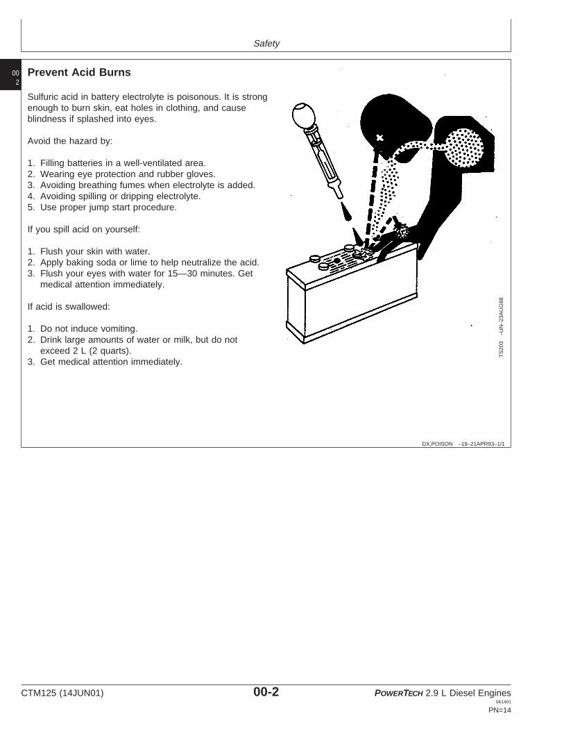
Prevent Acid Burns
TS
203
–UN
–23A
UG
88
Sulfuric acid in battery electrolyte is poisonous. It is strongenough to burn skin, eat holes in clothing, and causeblindness if splashed into eyes.
Avoid the hazard by:
1. Filling batteries in a well-ventilated area.2. Wearing eye protection and rubber gloves.3. Avoiding breathing fumes when electrolyte is added.4. Avoiding spilling or dripping electrolyte.5. Use proper jump start procedure.
If you spill acid on yourself:
1. Flush your skin with water.2. Apply baking soda or lime to help neutralize the acid.3. Flush your eyes with water for 15—30 minutes. Get
medical attention immediately.
If acid is swallowed:
1. Do not induce vomiting.2. Drink large amounts of water or milk, but do not
exceed 2 L (2 quarts).3. Get medical attention immediately.
CTM125 (14JUN01) 00-2 POWERTECH 2.9 L Diesel Engines061401
PN=14

Safety
003
DX,FLUID –19–03MAR93–1/1
Avoid High-Pressure Fluids
X98
11–U
N–2
3AU
G88
Escaping fluid under pressure can penetrate the skincausing serious injury.
Avoid the hazard by relieving pressure beforedisconnecting hydraulic or other lines. Tighten allconnections before applying pressure.
Search for leaks with a piece of cardboard. Protect handsand body from high pressure fluids.
If an accident occurs, see a doctor immediately. Any fluidinjected into the skin must be surgically removed within afew hours or gangrene may result. Doctors unfamiliar withthis type of injury should reference a knowledgeablemedical source. Such information is available from Deere& Company Medical Department in Moline, Illinois, U.S.A.
DX,WEAR –19–10SEP90–1/1
Wear Protective Clothing
TS
206
–UN
–23A
UG
88
Wear close fitting clothing and safety equipmentappropriate to the job.
Prolonged exposure to loud noise can cause impairmentor loss of hearing.
Wear a suitable hearing protective device such asearmuffs or earplugs to protect against objectionable oruncomfortable loud noises.
Operating equipment safely requires the full attention ofthe operator. Do not wear radio or music headphoneswhile operating machine.
CTM125 (14JUN01) 00-3 POWERTECH 2.9 L Diesel Engines061401
PN=15

Safety
004
DX,LOOSE –19–04JUN90–1/1
Service Machines Safely
TS
228
–UN
–23A
UG
88
Tie long hair behind your head. Do not wear a necktie,scarf, loose clothing, or necklace when you work nearmachine tools or moving parts. If these items were to getcaught, severe injury could result.
Remove rings and other jewelry to prevent electricalshorts and entanglement in moving parts.
DX,AIR –19–17FEB99–1/1
Work In Ventilated Area
TS
220
–UN
–23A
UG
88
Engine exhaust fumes can cause sickness or death. If it isnecessary to run an engine in an enclosed area, removethe exhaust fumes from the area with an exhaust pipeextension.
If you do not have an exhaust pipe extension, open thedoors and get outside air into the area
DX,CLEAN –19–04JUN90–1/1
Work in Clean Area
T66
42E
J–U
N–1
8OC
T88
Before starting a job:
• Clean work area and machine.• Make sure you have all necessary tools to do your job.• Have the right parts on hand.• Read all instructions thoroughly; do not attempt
shortcuts.
CTM125 (14JUN01) 00-4 POWERTECH 2.9 L Diesel Engines061401
PN=16

Safety
005
DX,PAINT –19–03MAR93–1/1
Remove Paint Before Welding or Heating
TS
220
–UN
–23A
UG
88
Avoid potentially toxic fumes and dust.
Hazardous fumes can be generated when paint is heatedby welding, soldering, or using a torch.
Do all work outside or in a well ventilated area. Dispose ofpaint and solvent properly.
Remove paint before welding or heating:
• If you sand or grind paint, avoid breathing the dust.Wear an approved respirator.
• If you use solvent or paint stripper, remove stripper withsoap and water before welding. Remove solvent orpaint stripper containers and other flammable materialfrom area. Allow fumes to disperse at least 15 minutesbefore welding or heating.
DX,TORCH –19–03MAR93–1/1
Avoid Heating Near Pressurized Fluid Lines
TS
953
–UN
–15M
AY
90
Flammable spray can be generated by heating nearpressurized fluid lines, resulting in severe burns toyourself and bystanders. Do not heat by welding,soldering, or using a torch near pressurized fluid lines orother flammable materials. Pressurized lines can beaccidentally cut when heat goes beyond the immediateflame area.
DX,LIGHT –19–04JUN90–1/1
Illuminate Work Area Safely
TS
223
–UN
–23A
UG
88
Illuminate your work area adequately but safely. Use aportable safety light for working inside or under themachine. Make sure the bulb is enclosed by a wire cage.The hot filament of an accidentally broken bulb can ignitespilled fuel or oil.
CTM125 (14JUN01) 00-5 POWERTECH 2.9 L Diesel Engines061401
PN=17

Safety
006
DX,LIFT –19–04JUN90–1/1
Use Proper Lifting Equipment
TS
226
–UN
–23A
UG
88
Lifting heavy components incorrectly can cause severeinjury or machine damage.
Follow recommended procedure for removal andinstallation of components in the manual.
DX,SERV –19–17FEB99–1/1
Practice Safe Maintenance
TS
218
–UN
–23A
UG
88
Understand service procedure before doing work. Keeparea clean and dry.
Never lubricate, service, or adjust machine while it ismoving. Keep hands, feet , and clothing frompower-driven parts. Disengage all power and operatecontrols to relieve pressure. Lower equipment to theground. Stop the engine. Remove the key. Allow machineto cool.
Securely support any machine elements that must beraised for service work.
Keep all parts in good condition and properly installed. Fixdamage immediately. Replace worn or broken parts.Remove any buildup of grease, oil, or debris.
On self-propelled equipment, disconnect battery groundcable (-) before making adjustments on electrical systemsor welding on machine.
On towed implements, disconnect wiring harnesses fromtractor before servicing electrical system components orwelding on machine.
CTM125 (14JUN01) 00-6 POWERTECH 2.9 L Diesel Engines061401
PN=18

Safety
007
DX,REPAIR –19–17FEB99–1/1
Use Proper Tools
TS
779
–UN
–08N
OV
89
Use tools appropriate to the work. Makeshift tools andprocedures can create safety hazards.
Use power tools only to loosen threaded parts andfasteners.
For loosening and tightening hardware, use the correctsize tools. DO NOT use U.S. measurement tools onmetric fasteners. Avoid bodily injury caused by slippingwrenches.
Use only service parts meeting John Deere specifications.
DX,DRAIN –19–03MAR93–1/1
Dispose of Waste Properly
TS
1133
–UN
–26N
OV
90
Improperly disposing of waste can threaten theenvironment and ecology. Potentially harmful waste usedwith John Deere equipment include such items as oil, fuel,coolant, brake fluid, filters, and batteries.
Use leakproof containers when draining fluids. Do not usefood or beverage containers that may mislead someoneinto drinking from them.
Do not pour waste onto the ground, down a drain, or intoany water source.
Air conditioning refrigerants escaping into the air candamage the Earth’s atmosphere. Government regulationsmay require a certified air conditioning service center torecover and recycle used air conditioning refrigerants.
Inquire on the proper way to recycle or dispose of wastefrom your local environmental or recycling center, or fromyour John Deere dealer.
CTM125 (14JUN01) 00-7 POWERTECH 2.9 L Diesel Engines061401
PN=19

Safety
008
DX,LIVE –19–25SEP92–1/1
Live With Safety
TS
231
–19–
07O
CT
88
Before returning machine to customer, make suremachine is functioning properly, especially the safetysystems. Install all guards and shields.
CTM125 (14JUN01) 00-8 POWERTECH 2.9 L Diesel Engines061401
PN=20

Group 01General Information
011
CD,CTM125,003 –19–04JAN01–1/1
Engine Identification
CD
3052
1–U
N–3
0AP
R98
CD
3052
2–U
N–1
7JU
N98
Saran Engine Plate
CD
3052
3–U
N–1
7JU
N98
Torreon Engine Plate
Engines can be identified from the serial number plate (A)located on the right-hand side of engine.
1. Each engine has a 13-digit John Deere engine serialnumber (B) identifying the producing factory, enginemodel designation, and a 6-digit sequential number.The following is an example:
CD3029D500000CD ................................. Producing factory
CD= Saran-FRANCEPE= Torreon-MEXICO
3029 .............................. Engine model designation3 = Number of cylinders029 = Total displacement (029 = 2.9 liters)
D .................................... Aspiration codeD= Naturally AspiratedT= Turbocharger
500000 .......................... Sequential serial number
2. The second line of information (C) identifies theengine/machine or OEM relationship. See “ENGINEAPPLICATION CHART” earlier in this manual.
3029DF1503029D ........................ See aboveF ................................. User code
AT= Agritalia-built tractorsF = OEM applicationsFG= Goldony (Italy)KV= John Deere KnoxvilleLV== John Deere Augusta
150 ............................. Application number
3. The second line can also contains the absorptioncoefficient (D) of smoke emissions (Saran-built enginesonly).
CTM125 (14JUN01) 01-1 POWERTECH 2.9 L Diesel Engines061401
PN=21

General Information
012
CD,CTM125,004 –19–01DEC97–1/1
OEM Engine Option Code Label
CD
3052
4–U
N–2
7MA
Y98
Option Code Label
An option code label is secured to the top of the valvecover and identifies the factory installed options on eachOEM engine to ensure correct parts acquisition.
Always provide option code information and engine basecode when ordering repair parts. A listing of option codesis given in Parts Catalogs and Operator’s Manual.
NOTE: Before “hot tank” cleaning, ensure that optioncodes are recorded elsewhere.
CD,CTM125,228 –19–01DEC97–1/1
Emission Certified Engine Label
CD
3069
7–U
N–1
7JU
N98
Emission Label
Emission certified engines have a label, like the oneshown, stuck on the rocker arm cover. Information on thislabel states the conditions this engine is emissioncertified.
CTM125 (14JUN01) 01-2 POWERTECH 2.9 L Diesel Engines061401
PN=22

BUY NOW Instant Download the
Complete Manual