component manual
TRANSCRIPT
JT25
Issue 1.0
Component Manual
053-2714 CMCMW®
JT25 Component Manual Foreword - 1
Foreword
Ditch Witch equipment is quality-engineered and manufactured to provide years of dependable service. To help you obtain this long and satisfactory service, we offer a Technical Information Manual that includes a Service Reference Manual, Troubleshooting Manual, Component Manual, Operator’s Manual, Parts Manual, and supplier service information for your unit.
The keys to long and productive equipment life are proper equipment operation, following a good maintenance program, and using original equipment replacement parts. A Ditch Witch dealer is your equipment partner in the underground construction business, and can provide you with professional Performance Parts and Service. If you need assistance in locating a dealer, visit our website at www.ditchwitch.com or write to the following address:
The Charles Machine Works, Inc.Attn: Marketing DepartmentPO Box 66Perry, OK 73077-0066USA
The descriptions and repair procedures contained in this guide were current as of publication date. However, The Charles Machine Works, Inc. reserves the right, as part of its normal product improvement policy, to modify or change specifications without notice.
We thank you for your patronage and confidence in Ditch Witch equipment.
Always use Ditch Witch replacement parts when servicing or repairing your equipment. For current part numbers, refer to your Ditch Witch Parts Manual or ProLink electronic parts catalog.
Foreword - 2 JT25 Component ManualIntroduction
IntroductionThis manual is an informational tool written for technicians with advanced skills, and is intended to be used with hydraulic and electrical schematics, diagrams, and electronic diagnostic tools to perform basic functional and troubleshooting tests.
Ultimately, a technician will depend on the tools provided and his own training and skills to find and fix the problem.
Related Publications
Part Number
Description Part Number
Description
053-1035 Cummins QS B4.5 Tier 3 053-2437 Parts Manual
053-2572 Cummins QS B4.5 Tier 4i 053-2593 Operator’s Manual
JT25 Component Manual Contents - 3
Contents
Foreword 1Introduction 2Related Publications 2Contents 3Service Precautions 5A 9B 17C 21D 65E 73F 79G 89H 95I 97J, K, L 99M, N, O 101P, Q 121R 131S 143T, U 165V 177W, X, Y, Z 195
Contents - 4 JT25 Component Manual
JT25 Component Manual Service Precautions - 5
Service Precautions
Chapter Contents
General Precautions . . . . . . . . . . . . . . . . . . . . . . . . . 6
Working Under Drilling Unit. . . . . . . . . . . . . . . . . . . 7
Welding Precautions . . . . . . . . . . . . . . . . . . . . . . . . 8
Washing Precautions . . . . . . . . . . . . . . . . . . . . . . . . 8
Electrical Precautions . . . . . . . . . . . . . . . . . . . . . . . 8
Hydraulic Precautions . . . . . . . . . . . . . . . . . . . . . . . 8
Service Precautions - 6 JT25 Component ManualService Precautions
Service Precautions
General Precautions
Read operator’s manual. Know how to use all controls before operating
machine. When you see this sign on the machine or in the manual, read it and use caution. Your safety is at stake.
NOTICES:
• Unless otherwise instructed, all service should be performed with engine off and disabled to prevent starting.
• Stop engine and apply parking brake, block tracks or otherwise prevent equipment from moving before inspecting, testing or performing any service or repairs.
• Always secure heavy components with suitable supports or lifting devices before attempting to remove.
• Allow engine, cooling system and hydraulic components to cool before inspecting, testing or performing any service or repairs.
• Always cap or plug hydraulic lines to prevent contamination, and mark for proper reassembly.
• Refer to manufacturer’s manuals or other vendor information for maintenance or repair instructions for purchased components, such as engines, pumps, valves, and hydraulic motors.
• Before inspecting, testing, or performing any service or repairs, lower unstowed attachments to ground.
• Disconnect battery, (-) negative cable first, before performing electrical repairs.
JT25 Component Manual Service Precautions - 7Service Precautions
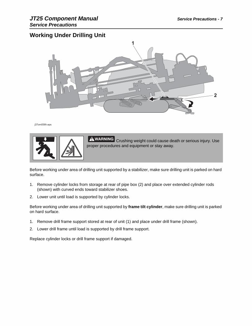
Working Under Drilling Unit
Before working under area of drilling unit supported by a stabilizer, make sure drilling unit is parked on hard surface.
1. Remove cylinder locks from storage at rear of pipe box (2) and place over extended cylinder rods (shown) with curved ends toward stabilizer shoes.
2. Lower unit until load is supported by cylinder locks.
Before working under area of drilling unit supported by frame tilt cylinder, make sure drilling unit is parked on hard surface.
1. Remove drill frame support stored at rear of unit (1) and place under drill frame (shown).
2. Lower drill frame until load is supported by drill frame support.
Replace cylinder locks or drill frame support if damaged.
Crushing weight could cause death or serious injury. Use proper procedures and equipment or stay away.
11
22
j37om056h.epsj37om056h.eps
Service Precautions - 8 JT25 Component ManualService Precautions
Welding Precautions
Washing Precautions
Electrical Precautions
Hydraulic Precautions
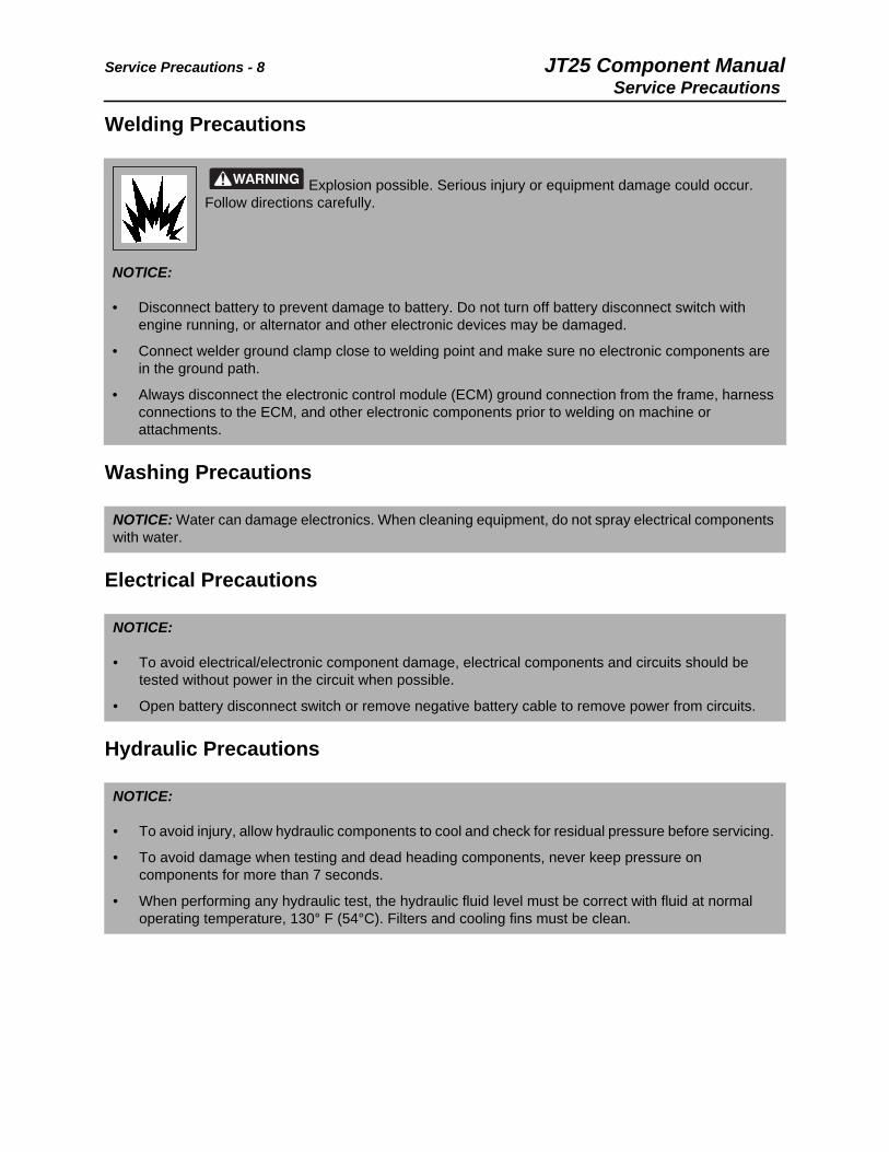
Explosion possible. Serious injury or equipment damage could occur. Follow directions carefully.
NOTICE:
• Disconnect battery to prevent damage to battery. Do not turn off battery disconnect switch with engine running, or alternator and other electronic devices may be damaged.
• Connect welder ground clamp close to welding point and make sure no electronic components are in the ground path.
• Always disconnect the electronic control module (ECM) ground connection from the frame, harness connections to the ECM, and other electronic components prior to welding on machine or attachments.
NOTICE: Water can damage electronics. When cleaning equipment, do not spray electrical components with water.
NOTICE:
• To avoid electrical/electronic component damage, electrical components and circuits should be tested without power in the circuit when possible.
• Open battery disconnect switch or remove negative battery cable to remove power from circuits.
NOTICE:
• To avoid injury, allow hydraulic components to cool and check for residual pressure before servicing.
• To avoid damage when testing and dead heading components, never keep pressure on components for more than 7 seconds.
• When performing any hydraulic test, the hydraulic fluid level must be correct with fluid at normal operating temperature, 130° F (54°C). Filters and cooling fins must be clean.
JT25 Component Manual A - 9Service Precautions
A
Chapter Contents
Accessory Socket . . . . . . . . . . . . . . . . . . . . . . . . . 10
Actuator, Rear Hood . . . . . . . . . . . . . . . . . . . . . . . . 11
Air Cleaner Assembly, Tier 3 . . . . . . . . . . . . . . . . . 12
Air Cleaner Assembly, Tier 4i . . . . . . . . . . . . . . . . 13
Alarm, Electric Strike . . . . . . . . . . . . . . . . . . . . . . . 14
Alarm, High Temperature Fluid Warning . . . . . . . 15
Alternator. . . . . . . . . . . . . . . . . . . . . . . . . . . . . . . . . 16
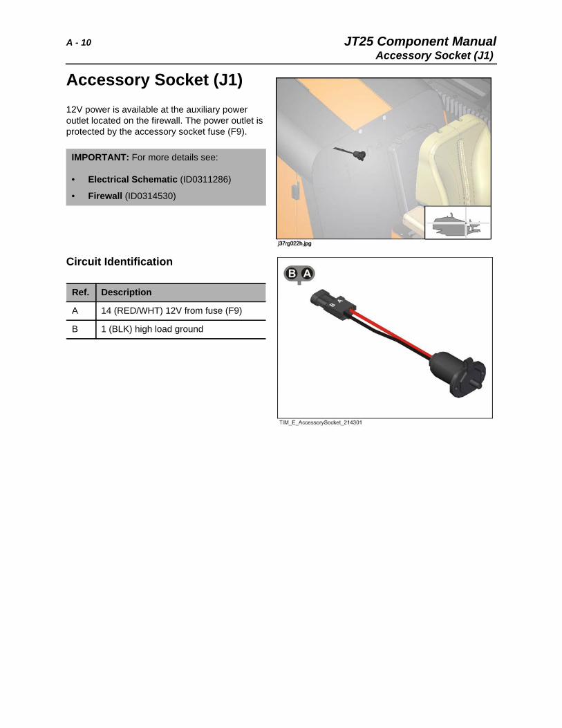
A - 10 JT25 Component ManualAccessory Socket (J1)
Accessory Socket (J1)12V power is available at the auxiliary power outlet located on the firewall. The power outlet is protected by the accessory socket fuse (F9).
Circuit Identification
IMPORTANT: For more details see:
• Electrical Schematic (ID0311286)
• Firewall (ID0314530)
Ref. Description
A 14 (RED/WHT) 12V from fuse (F9)
B 1 (BLK) high load ground
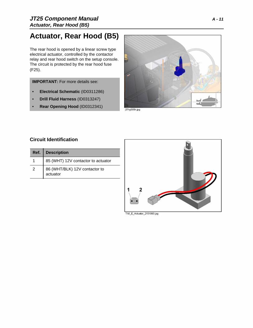
JT25 Component Manual A - 11Actuator, Rear Hood (B5)
Actuator, Rear Hood (B5)The rear hood is opened by a linear screw type electrical actuator, controlled by the contactor relay and rear hood switch on the setup console. The circuit is protected by the rear hood fuse (F25).
Circuit Identification
IMPORTANT: For more details see:
• Electrical Schematic (ID0311286)
• Drill Fluid Harness (ID0313247)
• Rear Opening Hood (ID0312341)
Ref. Description
1 85 (WHT) 12V contactor to actuator
2 86 (WHT/BLK) 12V contactor to actuator
A - 12 JT25 Component ManualAir Cleaner Assembly, Tier 3
Air Cleaner Assembly, Tier 3The Tier 3 engine air cleaner assembly features the standard two-stage filtration and a dust ejection valve. The filter restriction indicator is located at the electrical mounting center. See page 74.
IMPORTANT: For more details see:
• Intake System Tier 3 (ID0312624)
JT25 Component Manual A - 13Air Cleaner Assembly, Tier 4i
Air Cleaner Assembly, Tier 4iThe Tier 4i engine uses a direct flow unit with precleaner. The filter restriction indicator is located at the electrical mounting center. See page 74.
Replace filter element. Wipe dust and debris from inside.
IMPORTANT: For more details see:
• Intake System Tier 4i (ID0290494)
A - 14 JT25 Component ManualAlarm, ESID (LS2)
Alarm, ESID (LS2)The electric strike alarm is located below the operator seat, and is powered by an output signal from the ESID module.
The circuit is protected by the ESID/Remote Display fuse (F15).
See “ESID Module (U1)” on page 27.
Circuit Identification
IMPORTANT: For more details see:
• Electrical Schematic (ID0311286)
• Operator Station Left Harness (ID0313290)
• Operator Station (ID0315178)
Ref. Description
A (70) BRN 12V from pin 5 on ESID module
B (1A) BLK/RED medium load ground, pin 3 on ESID module
JT25 Component Manual A - 15Alarm, High Temperature Fluid Warning (LS1)
Alarm, High Temperature Fluid Warning (LS1)The hot hydraulic fluid audio warning alarm is located on the firewall. The circuit is protected by the display panel fuse (F17).
The ground circuit is completed to sound the alarm when the hydraulic fluid temperature switch closes, and signals the display panel.
The hydraulic fluid temperature switch is located on the hydraulic filter head. See page 81.
Circuit Identification
IMPORTANT: For more details see:
• Electrical Schematic (ID0311286)
• Firewall (ID0314530)
• Drill Fluid Harness (ID0313247)
Ref. Description
A 46 (GRN/WHT) 12V from display panel
B 1A (BLK/RED) medium load ground
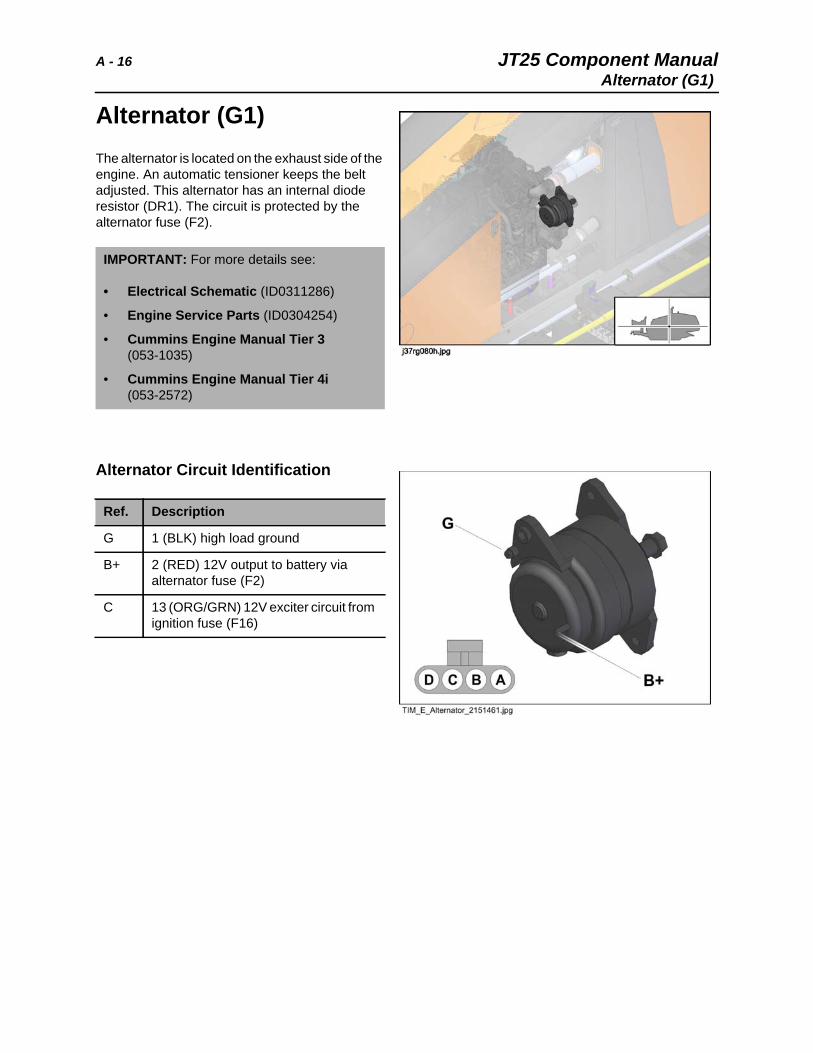
A - 16 JT25 Component ManualAlternator (G1)
Alternator (G1)The alternator is located on the exhaust side of the engine. An automatic tensioner keeps the belt adjusted. This alternator has an internal diode resistor (DR1). The circuit is protected by the alternator fuse (F2).
Alternator Circuit Identification
IMPORTANT: For more details see:
• Electrical Schematic (ID0311286)
• Engine Service Parts (ID0304254)
• Cummins Engine Manual Tier 3 (053-1035)
• Cummins Engine Manual Tier 4i (053-2572)
Ref. Description
G 1 (BLK) high load ground
B+ 2 (RED) 12V output to battery via alternator fuse (F2)
C 13 (ORG/GRN) 12V exciter circuit from ignition fuse (F16)
JT25 Component Manual B - 17Alternator (G1)
B
Chapter Contents
Batteries. . . . . . . . . . . . . . . . . . . . . . . . . . . . . . . . . . 18
Belt, Engine Drive . . . . . . . . . . . . . . . . . . . . . . . . . . 19
Brake, Ground Drive . . . . . . . See Track Drive Motor
Brake, Thrust. . . . . . . . . . . . . . . . . See Thrust Motor
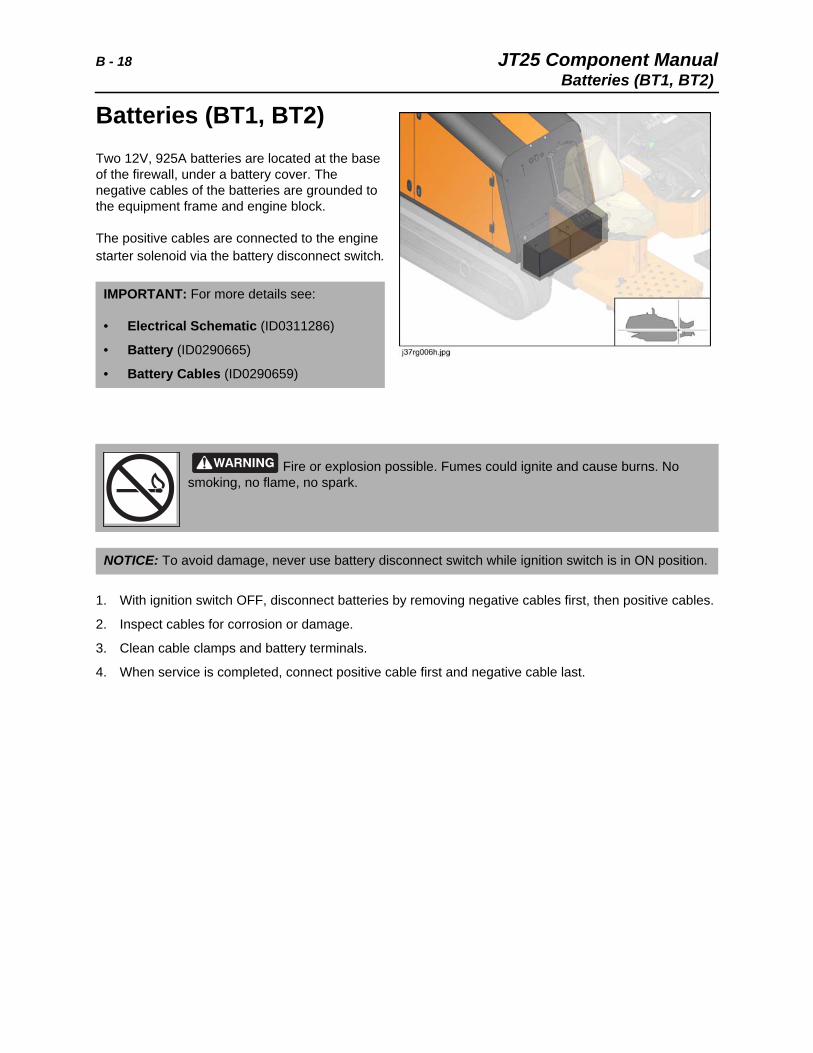
B - 18 JT25 Component ManualBatteries (BT1, BT2)
Batteries (BT1, BT2)Two 12V, 925A batteries are located at the base of the firewall, under a battery cover. The negative cables of the batteries are grounded to the equipment frame and engine block.
The positive cables are connected to the engine starter solenoid via the battery disconnect switch.
1. With ignition switch OFF, disconnect batteries by removing negative cables first, then positive cables.
2. Inspect cables for corrosion or damage.
3. Clean cable clamps and battery terminals.
4. When service is completed, connect positive cable first and negative cable last.
IMPORTANT: For more details see:
• Electrical Schematic (ID0311286)
• Battery (ID0290665)
• Battery Cables (ID0290659)
Fire or explosion possible. Fumes could ignite and cause burns. No smoking, no flame, no spark.
NOTICE: To avoid damage, never use battery disconnect switch while ignition switch is in ON position.
JT25 Component Manual B - 19Belt, Engine Drive
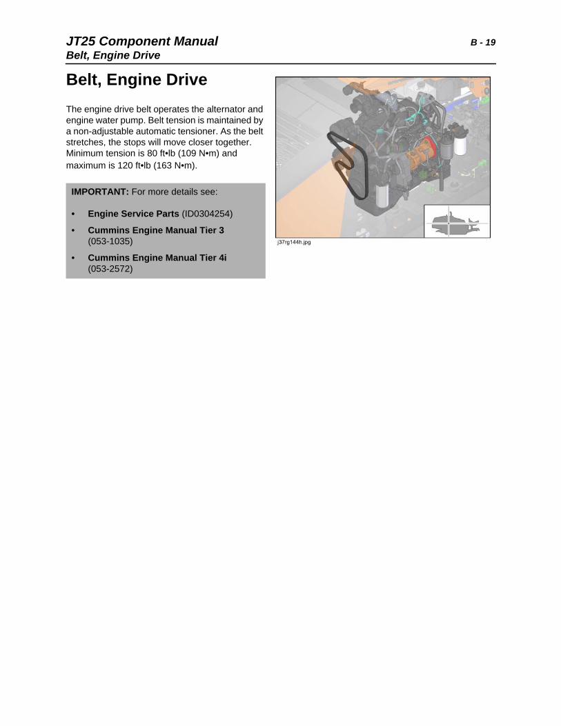
Belt, Engine DriveThe engine drive belt operates the alternator and engine water pump. Belt tension is maintained by a non-adjustable automatic tensioner. As the belt stretches, the stops will move closer together. Minimum tension is 80 ft•lb (109 N•m) and maximum is 120 ft•lb (163 N•m).
IMPORTANT: For more details see:
• Engine Service Parts (ID0304254)
• Cummins Engine Manual Tier 3 (053-1035)
• Cummins Engine Manual Tier 4i (053-2572)

B - 20 JT25 Component Manual
JT25 Component Manual C - 21
C
Chapter Contents
Console, Left Control . . . . . . . . . . . . . . . . . . . . . . . 23
• Carve Potentiometer . . . . . . . . . . . . . . . . . . . . . . . . . . . . . . . . . . . . . . . 23
• Console Control Switches . . . . . . . . . . . . . . . . . . . . . . . . . . . . . . . . . . . 25
• ESID Display Module . . . . . . . . . . . . . . . . . . . . . . . . . . . . . . . . . . . . . . 27
• Fluid Flow Potentiometer . . . . . . . . . . . . . . . . . . . . . . . . . . . . . . . . . . . 24
• Instrument Panel Display . . . . . . . . . . . . . . . . . . . . . . . . . . . . . . . . . . . 28
• Joystick Control. . . . . . . . . . . . . . . . . . . . . . . . . . . . . . . . . . . . . . . . . . . 30
Console, Right Control. . . . . . . . . . . . . . . . . . . . . . 32
• Console Control Switches . . . . . . . . . . . . . . . . . . . . . . . . . . . . . . . . . . . 32
• Gauges . . . . . . . . . . . . . . . . . . . . . . . . . . . . . . . . . . . . . . . . . . . . . . . . . 35
• Joystick Control. . . . . . . . . . . . . . . . . . . . . . . . . . . . . . . . . . . . . . . . . . . 36
• Status Indicator Lights. . . . . . . . . . . . . . . . . . . . . . . . . . . . . . . . . . . . . . 38
• Tracker Remote Display . . . . . . . . . . . . . . . . . . . . . . . . . . . . . . . . . . . . 39
Console, Setup . . . . . . . . . . . . . . . . . . . . . . . . . . . . 40
• Indicators. . . . . . . . . . . . . . . . . . . . . . . . . . . . . . . . . . . . . . . . . . . . . . . . 40
• Gauges . . . . . . . . . . . . . . . . . . . . . . . . . . . . . . . . . . . . . . . . . . . . . . . . . 40
• Control Switches . . . . . . . . . . . . . . . . . . . . . . . . . . . . . . . . . . . . . . . . . . 40
• Setup Control Valve . . . . . . . . . . . . . . . . . . . . . . . . . . . . . . . . . . . . . . . 45
Controller Area Network (CAN) . . . . . . . . . . . . . . . 46
• CAN Cables . . . . . . . . . . . . . . . . . . . . . . . . . . . . . . . . . . . . . . . . . . . . . 46
• CAN Junction Box . . . . . . . . . . . . . . . . . . . . . . . . . . . . . . . . . . . . . . . . . 47
• CAN Terminating Resistors. . . . . . . . . . . . . . . . . . . . . . . . . . . . . . . . . . 47
• CAN Diagnostic Connection . . . . . . . . . . . . . . . . . . . . . . . . . . . . . . . . . 48
Control Units, Electronic . . . . . . . . . . . . . . . . . . . . 49
• Engine Control Unit . . . . . . . . . . . . . . . . . . . . . . . . . . . . . . . . . . . . . . . . 49
• FMS Control Unit. . . . . . . . . . . . . . . . . . . . . . . . . . . . . . . . . . . . . . . . . . 50
C - 22 JT25 Component Manual
• Main Controller . . . . . . . . . . . . . . . . . . . . . . . . . . . . . . . . . . . . . . . . . . . 53
• Manual Drive Delay Timer Module . . . . . . . . . . . . . . . . . . . . . . . . . . . . 56
• ESID Display Module . . . . . . . . . . . . . . . . . . . . . . . . . . See Console, Left
• Tracker Control Remote Display Module . . . . . . . . . . See Console, Right
Current Transformer Coil (ESID) . . . . . . . . . . . . . . 57
Cylinders, Hydraulic . . . . . . . . . . . . . . . . . . . . . . . . 58
• Anchor Cylinder. . . . . . . . . . . . . . . . . . . . . . . . . . . . . . . . . . . . . . . . . . . 58
• Frame Tilt Cylinder . . . . . . . . . . . . . . . . . . . . . . . . . . . . . . . . . . . . . . . . 59
• Pipe Gripper Cylinder . . . . . . . . . . . . . . . . . . . . . . . . . . . . . . . . . . . . . . 59
• Pipe Lifter Cylinder . . . . . . . . . . . . . . . . . . . . . . . . . . . . . . . . . . . . . . . . 60
• Pipe Shuttle Stop Cylinder . . . . . . . . . . . . . . . . . . . . . . . . . . . . . . . . . . 61
• Seat Swing Cylinder . . . . . . . . . . . . . . . . . . . . . . . . . . . . . . . . . . . . . . . 61
• Stabilizer Cylinder . . . . . . . . . . . . . . . . . . . . . . . . . . . . . . . . . . . . . . . . . 62
• Wrench Clamp Cylinder . . . . . . . . . . . . . . . . . . . . . . . . . . . . . . . . . . . . 63
• Wrench Rotate Cylinder . . . . . . . . . . . . . . . . . . . . . . . . . . . . . . . . . . . . 64
JT25 Component Manual C - 23Console, Left Control
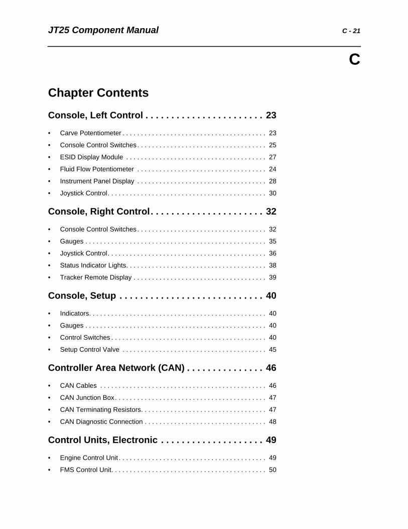
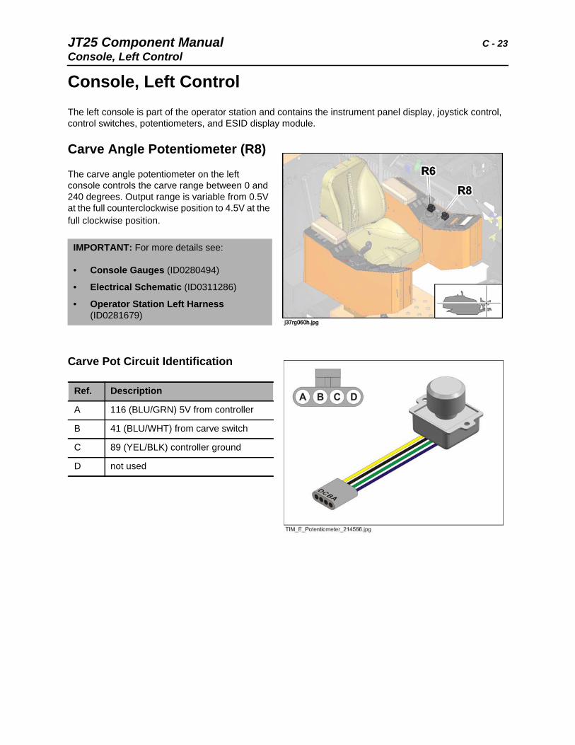
Console, Left ControlThe left console is part of the operator station and contains the instrument panel display, joystick control, control switches, potentiometers, and ESID display module.
Carve Angle Potentiometer (R8)
The carve angle potentiometer on the left console controls the carve range between 0 and 240 degrees. Output range is variable from 0.5V at the full counterclockwise position to 4.5V at the full clockwise position.
Carve Pot Circuit Identification
IMPORTANT: For more details see:
• Console Gauges (ID0280494)
• Electrical Schematic (ID0311286)
• Operator Station Left Harness (ID0281679)
Ref. Description
A 116 (BLU/GRN) 5V from controller
B 41 (BLU/WHT) from carve switch
C 89 (YEL/BLK) controller ground
D not used
C - 24 JT25 Component ManualConsole, Left Control
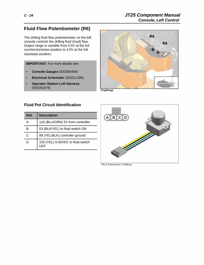
Fluid Flow Potentiometer (R6)
The drilling fluid flow potentiometer on the left console controls the drilling fluid (mud) flow. Output range is variable from 0.5V at the full counterclockwise position to 4.5V at the full clockwise position.
Fluid Pot Circuit Identification
IMPORTANT: For more details see:
• Console Gauges (ID0280494)
• Electrical Schematic (ID0311286)
• Operator Station Left Harness (ID0281679)
Ref. Description
A 116 (BLU/GRN) 5V from controller
B 53 (BLK/YEL) to fluid switch ON
C 89 (YEL/BLK) controller ground
D 150 (YEL) 0.05VDC to fluid switch OFF
JT25 Component Manual C - 25Console, Left Control
Left Console Control Switches
Component Identification
Circuit Identification
IMPORTANT: For more details see:
• Electrical Schematic (ID0311286)
• Operator Station Left Harness (ID0281679)
Ref. Description
S10 engine throttle switch
S11 carve set switch
S13 2-speed rotation switch
S14 pipe shuttle stop switch
Ref. Description
S10 engine throttle switch
1 116 (BLU/GRN) 5VDC from controller, throttle UP position
2 21 (YEL/ORG) power from throttle relay
3 13 (ORG/GRN) 12V from ignition fuse (F16), throttle DOWN position
S11 carve set switch
2 67 (WHT/BLU) controller
3 41 (BLU/WHT) carve potentiometer
S13 2-speed rotation switch
2 202 (BRN/YEL) to 2-speed relay (K11)
3 13 (ORG/GRN) 12V from ignition fuse (F16)
(cont. next page)
C - 26 JT25 Component ManualConsole, Left Control
Circuit Identification (Cont.)
Ref. Description
S14 pipe shuttle stop switch
1 152 (GRA/RED) from controller
2 13 (ORG/GRN) 12V from ignition fuse (F16)
3 152 (GRA/RED) from controller
4 191 (BLU/WHT) shuttle stop DOWN
5 13 (ORG/GRN) 12V from ignition fuse (F16)
6 190 (PUR/WHT) shuttle stop UP
JT25 Component Manual C - 27Console, Left Control
ESID Module (U1)
The ESID display module is a control unit and display located on the left operator console. The ESID module receives electric strike information from the current transformer coil and voltage limiter. When a strike occurs, outputs are sent to the warning strobe and alarm.
Circuit Identification
IMPORTANT: For more details see:
• Electrical Schematic (ID0311286)
• Operator Station Left Harness (ID0281679)
Ref. Description
A connection to voltage limiter (VR1)
B power connection to the frame harness
1 71 (WHT/PUR) ESID to strobe
2 20 (RED/YEL) fused ESID circuit
3 1A (BLK/RED) medium load ground
4 20 (RED/YEL) fused ESID circuit
5 70 (BRN) to ESID alarm
C EDT connection to the frame harness
D connection to ESID current transformer coil
C - 28 JT25 Component ManualConsole, Left Control
Instrument Panel Display (U7)
Circuit Identification Pinout
IMPORTANT: For more details see:
• Electrical Schematic (ID0311286)
• Console Gauges (ID0280494)
Ref. Description
1 124 (WHT) USB D-
2 not used
3 46 (GRN/WHT) to hot fluid alarm
4 not used
5 28 (WHT/BRN) from drill fluid speed sensor
6 not used
7 not used
8 39 (GRA/BLK) from hydraulic high temperature switch
9 not used
10 not used
11 not used
12 not used
13 125 (GRA) shield
14 23 (GRN) CAN-Low
15 not used
16 not used
JT25 Component Manual C - 29Console, Left Control
Circuit Identification Pinout (Cont.)
Ref. Description
17 not used
18 not used
19 31 (BRN) from coolant level sensor
20 38 (GRA/YEL) from hydraulic filter switch
21 1B (BLK/BLU) low load ground
22 not used
23 not used
24 123 (GRN) USB D+
25 122 (RED) VBUS
26 22 (YEL) CAN-High
27 40 (ORG/PUR) CAN fuse to display
28 40 (ORG/PUR) CAN fuse to display
29 1A (BLK/RED) medium load ground
30 not used
31 not used
32 not used
33 not used
34 not used
35 not used
C - 30 JT25 Component ManualConsole, Left Control
Joystick Control, Left (E3)
A left console dual axis joystick (E3) controls pipe and wrench functions.
Component Identification/Pinout
IMPORTANT: For more details see:
• Electrical Schematic (ID0311286)
• Operator Station Left Harness (ID0281679)
Ref. Description
A pipe gripper switch
B pipe shuttle switch
C pipe lift switch
D pipe lubricator switch
E cruise set/resume switch
1 13 (ORG/GRN) fused ignition circuit
2 116 (BLU/GRN) 5V output from controller
3 163 (PUR/YEL) rear wrench relay to rear wrench solenoid
4 29 (TAN) shuttle switch to controller
5 34 (BLU) pipe lift switch to controller
6 37 (GRN/BLU) 2.5V output from resistor module
7 42 (GRN) pipe grip switch to controller
8 56 (TAN/WHT) controller to cruise switch and tether creep
9 146 (PUR/ORG) front wrench open to diode pack
10 119 (GRA) controller to pipe lubricator solenoid
11 147 (PUR/WHT) rear wrench open to diode pack
12 159 (BRN/GRN) front wrench joystick to front wrench relay
JT25 Component Manual C - 31Console, Left Control
Optional Joystick (E5) Circuit Identification Pinout
Ref. Description
A rear wrench switch
B front wrench switch
C shuttle extend switch
D shuttle retract switch
E pipe lift switch
F pipe grip switch
1 116 (BLU/GRN) 5V output from controller
2 147 (PUR/WHT) rear wrench open to diode pack
3 159 (BRN/GRN) front wrench joystick to front wrench relay
4 163 (PUR/YEL) rear wrench relay to rear wrench solenoid
5 172 (TAN/BLU) joystick y-axis output to controller
6 89 (YEL/BLK) controller to joystick ground
1 13 (ORG/GRN) fused ignition circuit
2 116 (BLU/GRN) 5V output from controller
3 1A (BLK/RED) medium load ground
4 29 (TAN) shuttle switch to controller
5 34 (BLU) pipe lift switch to controller
6 37 (GRN/BLU) 2.5V output from resistor module
7 42 (GRN) pipe grip switch to controller
8 146 (PUR/ORG) front wrench open to diode pack
C - 32 JT25 Component ManualConsole, Right Control
Console, Right ControlThe right console is part of the operator station and contains diagnostic and status lights, control switches, gauges, tracker remote display, and joystick control.
Right Console Control Switches
Switch Identification
Right Console Control Switches
Switch Identification
IMPORTANT: For more details see:
• Electrical Schematic (ID0311286)
• Operator Station Right Harness (ID0281876)
Ref. Description
S3 remote engine stop switch
S4 remote engine start switch
Ref. Description
S9 anchor enable switch
S12 add pipe/manual/remove pipe switch
S17 operator station rotation (swing) switch
JT25 Component Manual C - 33Console, Right Control
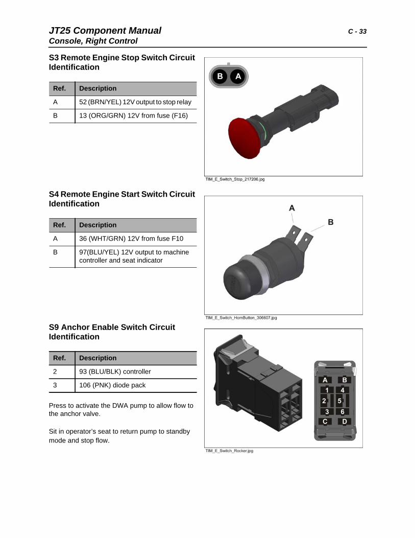
S3 Remote Engine Stop Switch Circuit Identification
S4 Remote Engine Start Switch Circuit Identification
S9 Anchor Enable Switch Circuit Identification
Press to activate the DWA pump to allow flow to the anchor valve.
Sit in operator’s seat to return pump to standby mode and stop flow.
Ref. Description
A 52 (BRN/YEL) 12V output to stop relay
B 13 (ORG/GRN) 12V from fuse (F16)
Ref. Description
A 36 (WHT/GRN) 12V from fuse F10
B 97(BLU/YEL) 12V output to machine controller and seat indicator
Ref. Description
2 93 (BLU/BLK) controller
3 106 (PNK) diode pack
C - 34 JT25 Component ManualConsole, Right Control
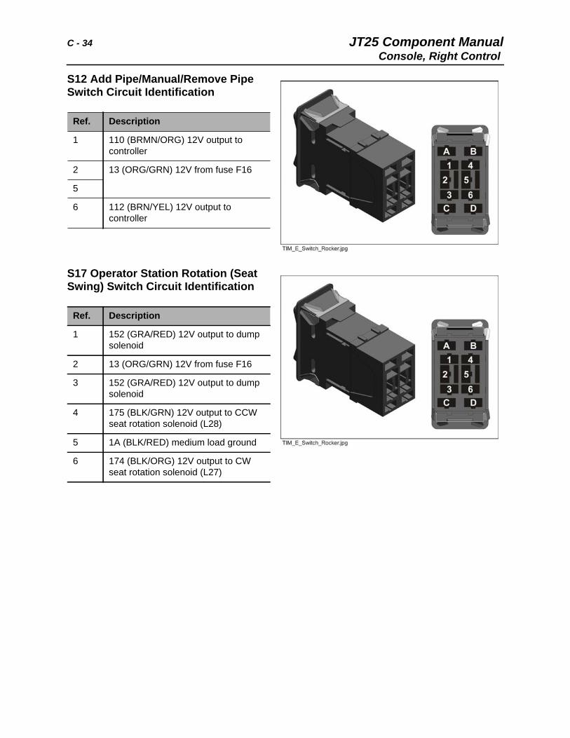
S12 Add Pipe/Manual/Remove Pipe Switch Circuit Identification
S17 Operator Station Rotation (Seat Swing) Switch Circuit Identification
Ref. Description
1 110 (BRMN/ORG) 12V output to controller
2 13 (ORG/GRN) 12V from fuse F16
5
6 112 (BRN/YEL) 12V output to controller
Ref. Description
1 152 (GRA/RED) 12V output to dump solenoid
2 13 (ORG/GRN) 12V from fuse F16
3 152 (GRA/RED) 12V output to dump solenoid
4 175 (BLK/GRN) 12V output to CCW seat rotation solenoid (L28)
5 1A (BLK/RED) medium load ground
6 174 (BLK/ORG) 12V output to CW seat rotation solenoid (L27)
JT25 Component Manual C - 35Console, Right Control
Gauges, Right Console
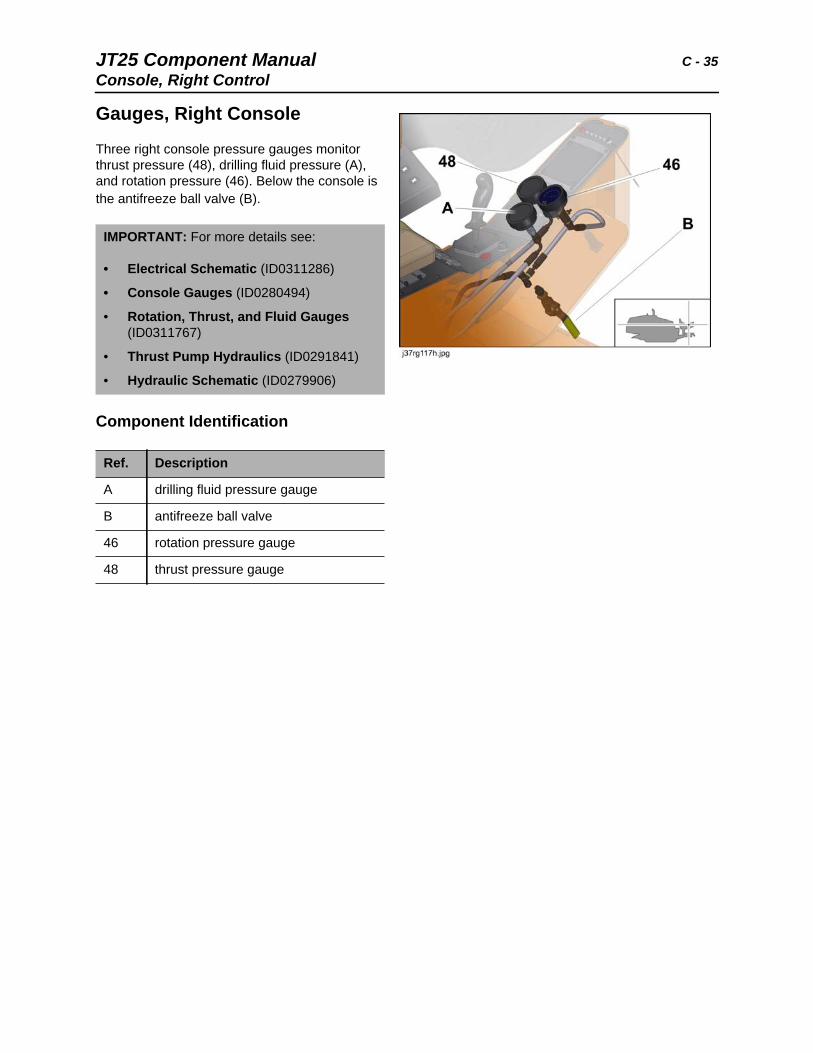
Three right console pressure gauges monitor thrust pressure (48), drilling fluid pressure (A), and rotation pressure (46). Below the console is the antifreeze ball valve (B).
Component Identification
IMPORTANT: For more details see:
• Electrical Schematic (ID0311286)
• Console Gauges (ID0280494)
• Rotation, Thrust, and Fluid Gauges (ID0311767)
• Thrust Pump Hydraulics (ID0291841)
• Hydraulic Schematic (ID0279906)
Ref. Description
A drilling fluid pressure gauge
B antifreeze ball valve
46 rotation pressure gauge
48 thrust pressure gauge
C - 36 JT25 Component ManualConsole, Right Control
Joystick Control, Right (E1)
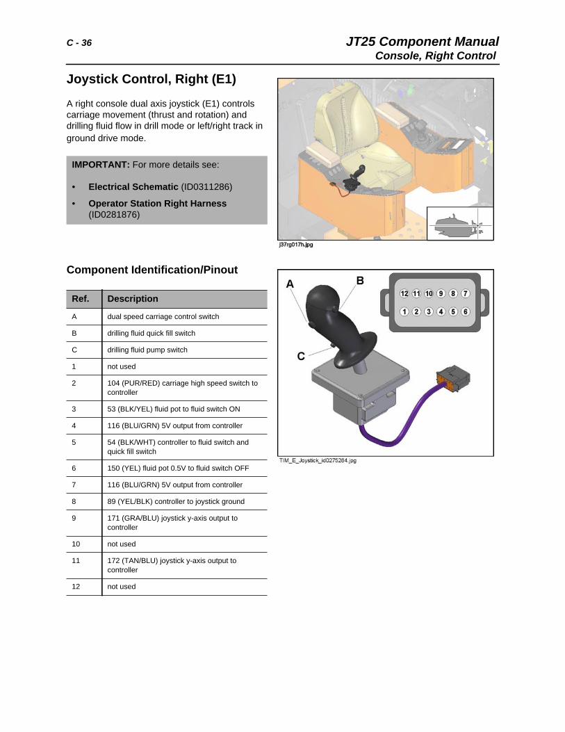
A right console dual axis joystick (E1) controls carriage movement (thrust and rotation) and drilling fluid flow in drill mode or left/right track in ground drive mode.
Component Identification/Pinout
IMPORTANT: For more details see:
• Electrical Schematic (ID0311286)
• Operator Station Right Harness (ID0281876)
Ref. Description
A dual speed carriage control switch
B drilling fluid quick fill switch
C drilling fluid pump switch
1 not used
2 104 (PUR/RED) carriage high speed switch to controller
3 53 (BLK/YEL) fluid pot to fluid switch ON
4 116 (BLU/GRN) 5V output from controller
5 54 (BLK/WHT) controller to fluid switch and quick fill switch
6 150 (YEL) fluid pot 0.5V to fluid switch OFF
7 116 (BLU/GRN) 5V output from controller
8 89 (YEL/BLK) controller to joystick ground
9 171 (GRA/BLU) joystick y-axis output to controller
10 not used
11 172 (TAN/BLU) joystick y-axis output to controller
12 not used
JT25 Component Manual C - 37Console, Right Control
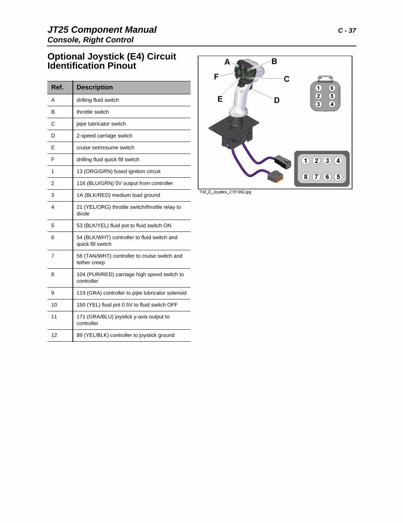
Optional Joystick (E4) Circuit Identification Pinout
Ref. Description
A drilling fluid switch
B throttle switch
C pipe lubricator switch
D 2-speed carriage switch
E cruise set/resume switch
F drilling fluid quick fill switch
1 13 (ORG/GRN) fused ignition circuit
2 116 (BLU/GRN) 5V output from controller
3 1A (BLK/RED) medium load ground
4 21 (YEL/ORG) throttle switch/throttle relay to diode
5 53 (BLK/YEL) fluid pot to fluid switch ON
6 54 (BLK/WHT) controller to fluid switch and quick fill switch
7 56 (TAN/WHT) controller to cruise switch and tether creep
8 104 (PUR/RED) carriage high speed switch to controller
9 119 (GRA) controller to pipe lubricator solenoid
10 150 (YEL) fluid pot 0.5V to fluid switch OFF
11 171 (GRA/BLU) joystick y-axis output to controller
12 89 (YEL/BLK) controller to joystick ground
C - 38 JT25 Component ManualConsole, Right Control
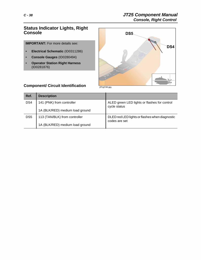
Status Indicator Lights, Right Console
Component/ Circuit Identification
IMPORTANT: For more details see:
• Electrical Schematic (ID0311286)
• Console Gauges (ID0280494)
• Operator Station Right Harness (ID0281876)
Ref. Description
DS4 141 (PNK) from controller
1A (BLK/RED) medium load ground
ALED green LED lights or flashes for control cycle status
DS5 113 (TAN/BLK) from controller
1A (BLK/RED) medium load ground
DLED red LED lights or flashes when diagnostic codes are set
JT25 Component Manual C - 39Console, Right Control
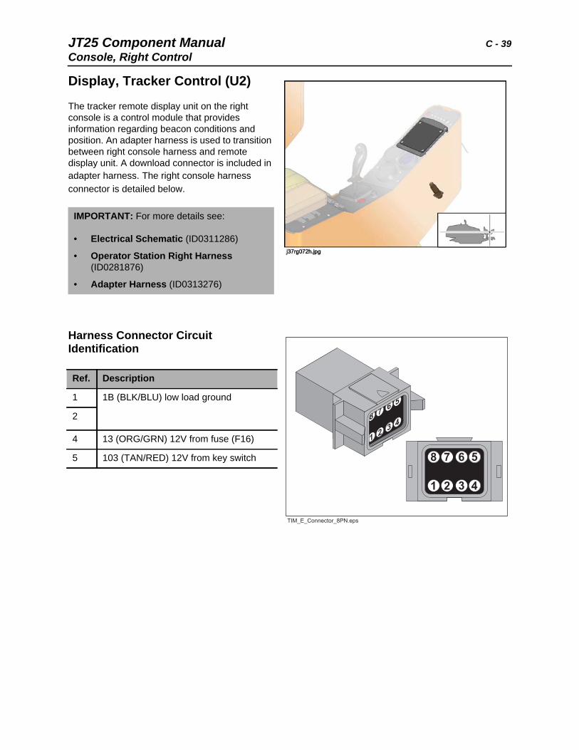
Display, Tracker Control (U2)
The tracker remote display unit on the right console is a control module that provides information regarding beacon conditions and position. An adapter harness is used to transition between right console harness and remote display unit. A download connector is included in adapter harness. The right console harness connector is detailed below.
Harness Connector Circuit Identification
IMPORTANT: For more details see:
• Electrical Schematic (ID0311286)
• Operator Station Right Harness (ID0281876)
• Adapter Harness (ID0313276)
Ref. Description
1 1B (BLK/BLU) low load ground
2
4 13 (ORG/GRN) 12V from fuse (F16)
5 103 (TAN/RED) 12V from key switch
C - 40 JT25 Component ManualConsole, Setup
Console, SetupThe setup console located at the rear of the unit contains the cold start wait indicator (not shown), rear hood switch, ignition switch, engine shutdown override switch, track override switches, tether control, and the setup hydraulic control valve.
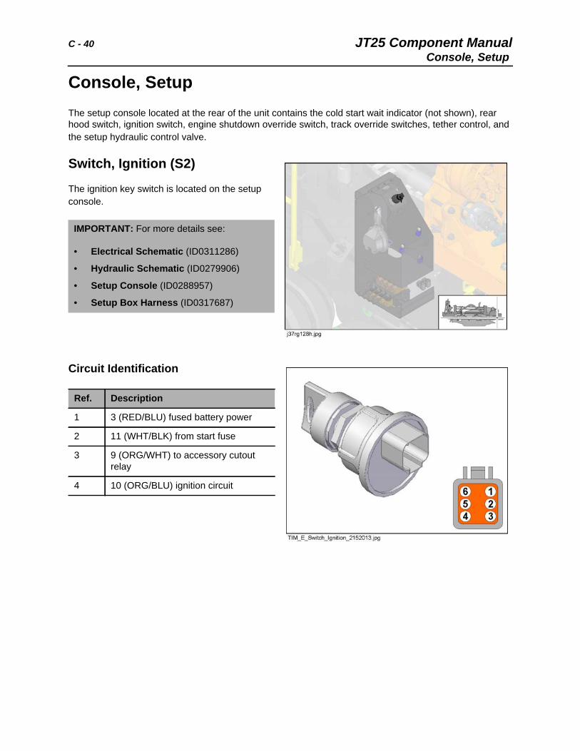
Switch, Ignition (S2)
The ignition key switch is located on the setup console.
Circuit Identification
IMPORTANT: For more details see:
• Electrical Schematic (ID0311286)
• Hydraulic Schematic (ID0279906)
• Setup Console (ID0288957)
• Setup Box Harness (ID0317687)
Ref. Description
1 3 (RED/BLU) fused battery power
2 11 (WHT/BLK) from start fuse
3 9 (ORG/WHT) to accessory cutout relay
4 10 (ORG/BLU) ignition circuit
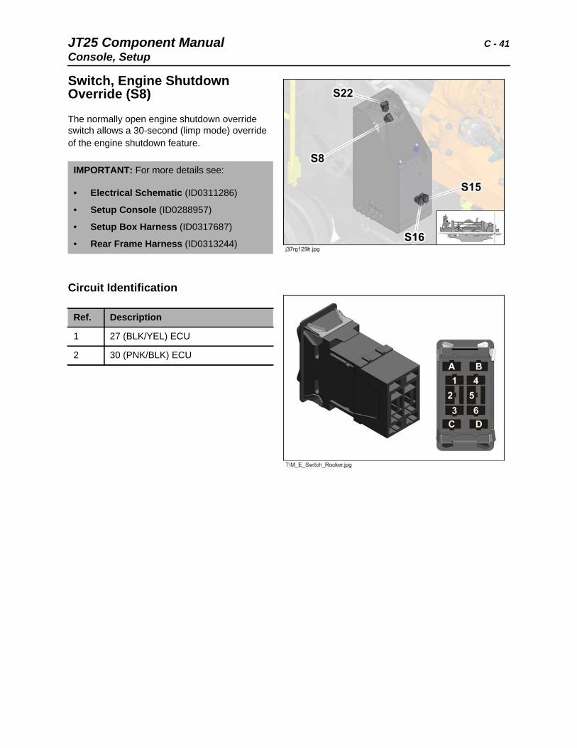
JT25 Component Manual C - 41Console, Setup
Switch, Engine Shutdown Override (S8)
The normally open engine shutdown override switch allows a 30-second (limp mode) override of the engine shutdown feature.
Circuit Identification
IMPORTANT: For more details see:
• Electrical Schematic (ID0311286)
• Setup Console (ID0288957)
• Setup Box Harness (ID0317687)
• Rear Frame Harness (ID0313244)
Ref. Description
1 27 (BLK/YEL) ECU
2 30 (PNK/BLK) ECU
C - 42 JT25 Component ManualConsole, Setup
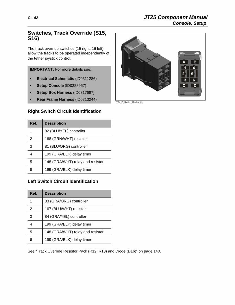
Switches, Track Override (S15, S16)
The track override switches (15 right, 16 left) allow the tracks to be operated independently of the tether joystick control.
Right Switch Circuit Identification
Left Switch Circuit Identification
See “Track Override Resistor Pack (R12, R13) and Diode (D16)” on page 140.
IMPORTANT: For more details see:
• Electrical Schematic (ID0311286)
• Setup Console (ID0288957)
• Setup Box Harness (ID0317687)
• Rear Frame Harness (ID0313244)
Ref. Description
1 82 (BLU/YEL) controller
2 168 (GRN/WHT) resistor
3 81 (BLU/ORG) controller
4 199 (GRA/BLK) delay timer
5 148 (GRA/WHT) relay and resistor
6 199 (GRA/BLK) delay timer
Ref. Description
1 83 (GRA/ORG) controller
2 167 (BLU/WHT) resistor
3 84 (GRA/YEL) controller
4 199 (GRA/BLK) delay timer
5 148 (GRA/WHT) relay and resistor
6 199 (GRA/BLK) delay timer
JT25 Component Manual C - 43Console, Setup
Switch, Rear Hood (S22)
The rear hood switch controls the contactor relay to power the linear screw type actuator that raises or lowers the rear hood. Power is supplied from the 40A rear door fuse (F25).
Circuit Identification
IMPORTANT: For more details see:
• Electrical Schematic (ID0311286)
• Setup Console (ID0288957)
• Setup Box Harness (ID0317687)
• Rear Frame Harness (ID0313244)
Ref. Description
1 76 (TAN/ORG) actuator UP
2 12 (ORG) 12V from fuse (F11)
3 77 (TAN/GRN) actuator DOWN
C - 44 JT25 Component ManualConsole, Setup
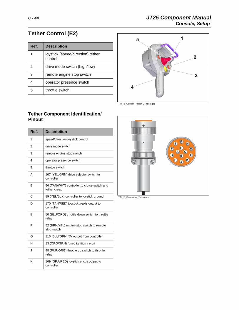
Tether Control (E2)
Tether Component Identification/Pinout
Ref. Description
1 joystick (speed/direction) tether control
2 drive mode switch (high/low)
3 remote engine stop switch
4 operator presence switch
5 throttle switch
Ref. Description
1 speed/direction joystick control
2 drive mode switch
3 remote engine stop switch
4 operator presence switch
5 throttle switch
A 107 (YEL/GRN) drive selector switch to controller
B 56 (TAN/WHT) controller to cruise switch and tether creep
C 89 (YEL/BLK) controller to joystick ground
D 170 (TAN/RED) joystick x-axis output to controller
E 50 (BLU/ORG) throttle down switch to throttle relay
F 52 (BRN/YEL) engine stop switch to remote stop switch
G 116 (BLU/GRN) 5V output from controller
H 13 (ORG/GRN) fused ignition circuit
J 48 (PUR/ORG) throttle up switch to throttle relay
K 169 (GRA/RED) joystick y-axis output to controller
JT25 Component Manual C - 45Console, Setup
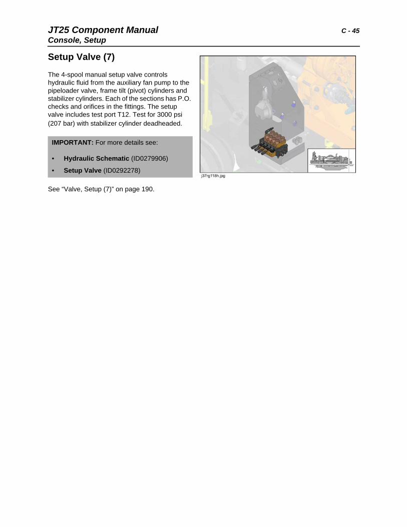
Setup Valve (7)
The 4-spool manual setup valve controls hydraulic fluid from the auxiliary fan pump to the pipeloader valve, frame tilt (pivot) cylinders and stabilizer cylinders. Each of the sections has P.O. checks and orifices in the fittings. The setup valve includes test port T12. Test for 3000 psi (207 bar) with stabilizer cylinder deadheaded.
See “Valve, Setup (7)” on page 190.
IMPORTANT: For more details see:
• Hydraulic Schematic (ID0279906)
• Setup Valve (ID0292278)
C - 46 JT25 Component ManualController Area Network (CAN)
Controller Area Network (CAN)The Engine Control Unit (ECU) communicates via the J1939 Controller Area Network (CAN) to the panel display.
CAN Cables
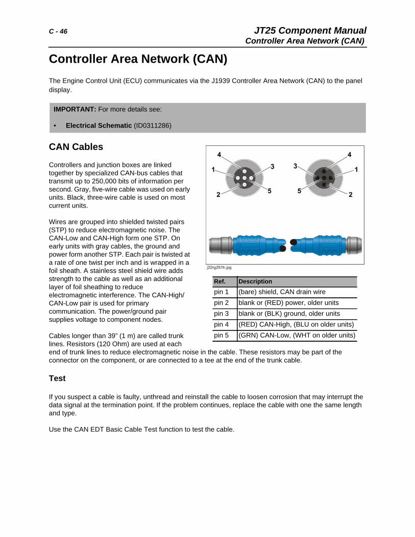
Controllers and junction boxes are linked together by specialized CAN-bus cables that transmit up to 250,000 bits of information per second. Gray, five-wire cable was used on early units. Black, three-wire cable is used on most current units.
Wires are grouped into shielded twisted pairs (STP) to reduce electromagnetic noise. The CAN-Low and CAN-High form one STP. On early units with gray cables, the ground and power form another STP. Each pair is twisted at a rate of one twist per inch and is wrapped in a foil sheath. A stainless steel shield wire adds strength to the cable as well as an additional layer of foil sheathing to reduce electromagnetic interference. The CAN-High/CAN-Low pair is used for primary communication. The power/ground pair supplies voltage to component nodes.
Cables longer than 39” (1 m) are called trunk lines. Resistors (120 Ohm) are used at each end of trunk lines to reduce electromagnetic noise in the cable. These resistors may be part of the connector on the component, or are connected to a tee at the end of the trunk cable.
Test
If you suspect a cable is faulty, unthread and reinstall the cable to loosen corrosion that may interrupt the data signal at the termination point. If the problem continues, replace the cable with one the same length and type.
Use the CAN EDT Basic Cable Test function to test the cable.
IMPORTANT: For more details see:
• Electrical Schematic (ID0311286)
Ref. Descriptionpin 1 (bare) shield, CAN drain wirepin 2 blank or (RED) power, older unitspin 3 blank or (BLK) ground, older unitspin 4 (RED) CAN-High, (BLU on older units)pin 5 (GRN) CAN-Low, (WHT on older units)
JT25 Component Manual C - 47Controller Area Network (CAN)
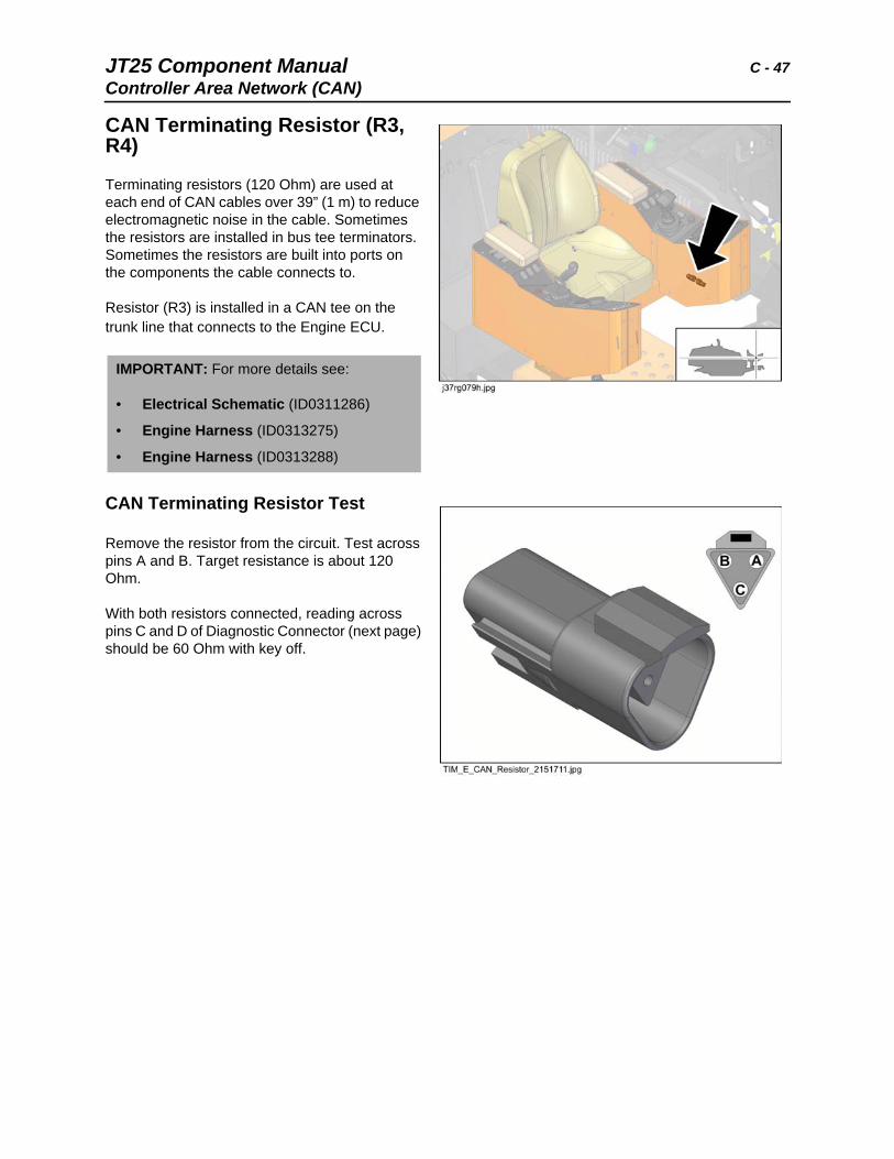
CAN Terminating Resistor (R3, R4)
Terminating resistors (120 Ohm) are used at each end of CAN cables over 39” (1 m) to reduce electromagnetic noise in the cable. Sometimes the resistors are installed in bus tee terminators. Sometimes the resistors are built into ports on the components the cable connects to.
Resistor (R3) is installed in a CAN tee on the trunk line that connects to the Engine ECU.
CAN Terminating Resistor Test
Remove the resistor from the circuit. Test across pins A and B. Target resistance is about 120 Ohm.
With both resistors connected, reading across pins C and D of Diagnostic Connector (next page) should be 60 Ohm with key off.
IMPORTANT: For more details see:
• Electrical Schematic (ID0311286)
• Engine Harness (ID0313275)
• Engine Harness (ID0313288)
C - 48 JT25 Component ManualController Area Network (CAN)
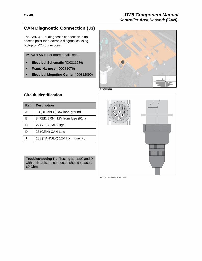
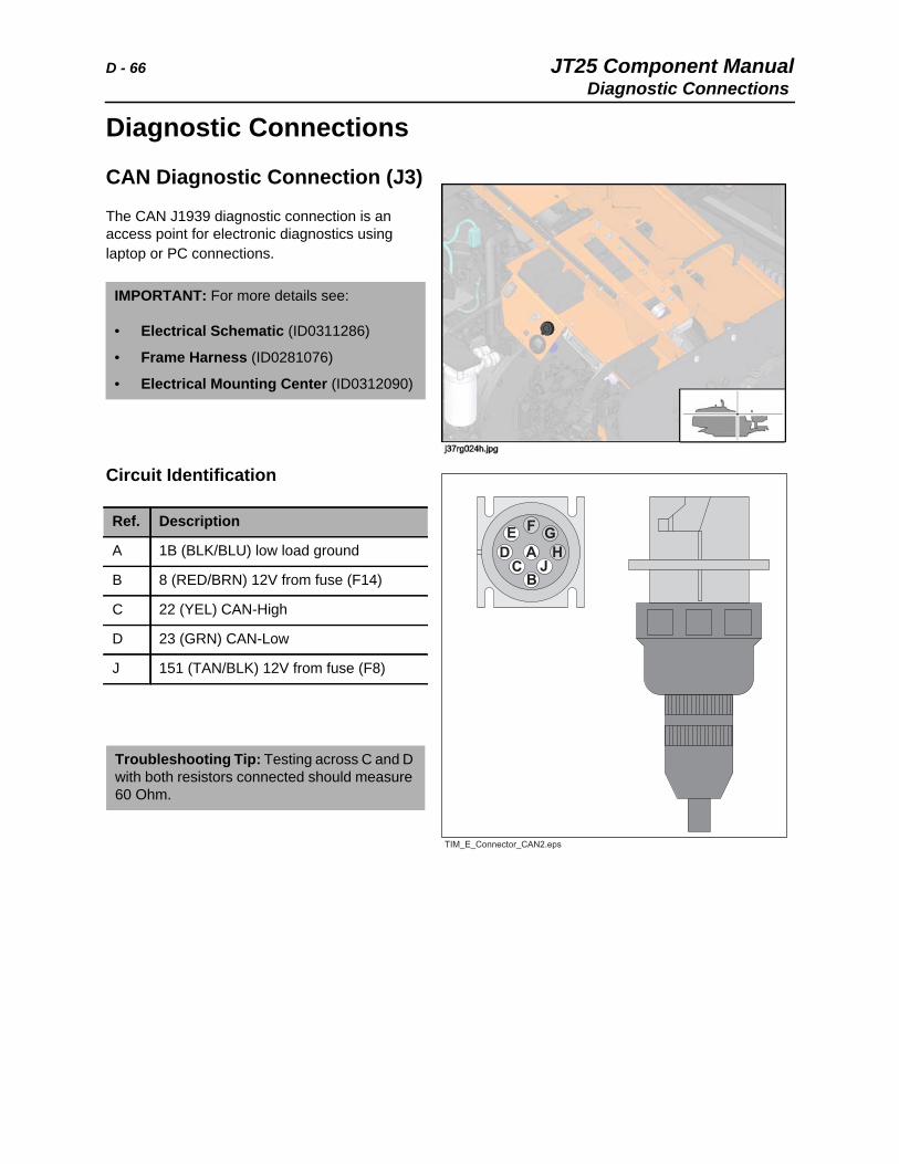
CAN Diagnostic Connection (J3)
The CAN J1939 diagnostic connection is an access point for electronic diagnostics using laptop or PC connections.
Circuit Identification
IMPORTANT: For more details see:
• Electrical Schematic (ID0311286)
• Frame Harness (ID0281076)
• Electrical Mounting Center (ID0312090)
Ref. Description
A 1B (BLK/BLU) low load ground
B 8 (RED/BRN) 12V from fuse (F14)
C 22 (YEL) CAN-High
D 23 (GRN) CAN-Low
J 151 (TAN/BLK) 12V from fuse (F8)
Troubleshooting Tip: Testing across C and D with both resistors connected should measure 60 Ohm.
JT25 Component Manual C - 49Control Units, Electronic
Control Units, ElectronicElectronic control units (controllers) are programmed to send voltage outputs to components based on electronic input signals from other components. For example, if input from the engine temperature sensor shows the engine temperature to be out of the desirable range and higher than normal, the main controller will decrease voltage output to the proportional solenoid on the fan motor. Input and output signals can be either digital or analog.
Controllers are also programmed to identify system faults and disable affected functions to protect system components. Faults are displayed as diagnostic codes on the tachometer display.
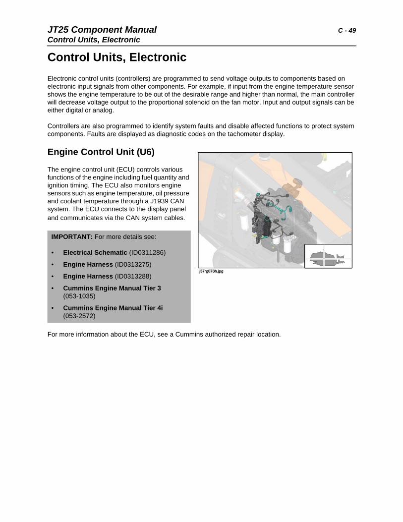
Engine Control Unit (U6)
The engine control unit (ECU) controls various functions of the engine including fuel quantity and ignition timing. The ECU also monitors engine sensors such as engine temperature, oil pressure and coolant temperature through a J1939 CAN system. The ECU connects to the display panel and communicates via the CAN system cables.
For more information about the ECU, see a Cummins authorized repair location.
IMPORTANT: For more details see:
• Electrical Schematic (ID0311286)
• Engine Harness (ID0313275)
• Engine Harness (ID0313288)
• Cummins Engine Manual Tier 3 (053-1035)
• Cummins Engine Manual Tier 4i (053-2572)
C - 50 JT25 Component ManualControl Units, Electronic
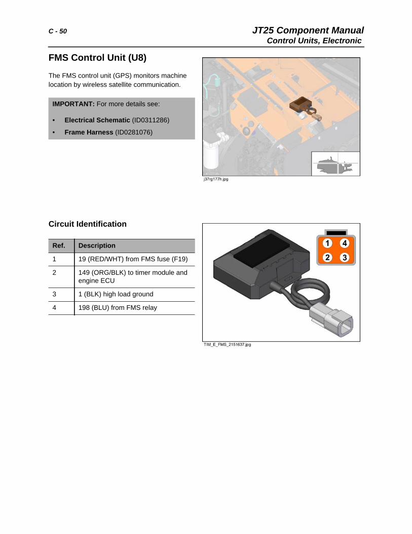
FMS Control Unit (U8)
The FMS control unit (GPS) monitors machine location by wireless satellite communication.
Circuit Identification
IMPORTANT: For more details see:
• Electrical Schematic (ID0311286)
• Frame Harness (ID0281076)
Ref. Description
1 19 (RED/WHT) from FMS fuse (F19)
2 149 (ORG/BLK) to timer module and engine ECU
3 1 (BLK) high load ground
4 198 (BLU) from FMS relay
JT25 Component Manual C - 51Control Units, Electronic
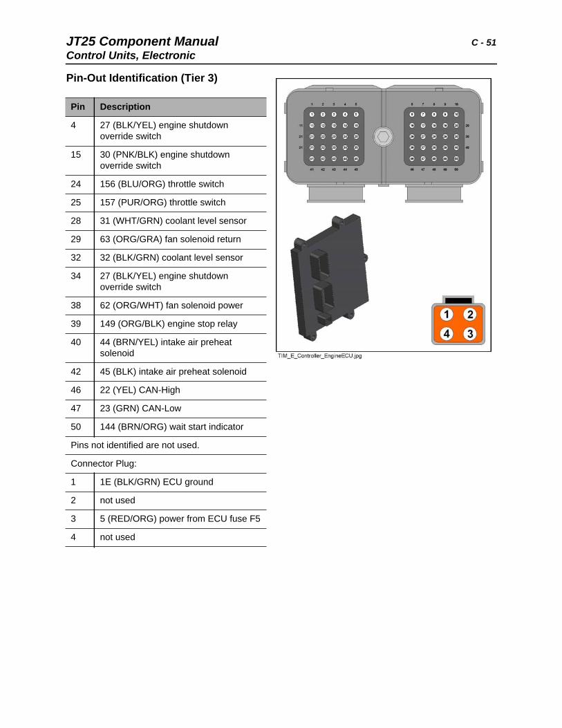
Pin-Out Identification (Tier 3)
Pin Description
4 27 (BLK/YEL) engine shutdown override switch
15 30 (PNK/BLK) engine shutdown override switch
24 156 (BLU/ORG) throttle switch
25 157 (PUR/ORG) throttle switch
28 31 (WHT/GRN) coolant level sensor
29 63 (ORG/GRA) fan solenoid return
32 32 (BLK/GRN) coolant level sensor
34 27 (BLK/YEL) engine shutdown override switch
38 62 (ORG/WHT) fan solenoid power
39 149 (ORG/BLK) engine stop relay
40 44 (BRN/YEL) intake air preheat solenoid
42 45 (BLK) intake air preheat solenoid
46 22 (YEL) CAN-High
47 23 (GRN) CAN-Low
50 144 (BRN/ORG) wait start indicator
Pins not identified are not used.
Connector Plug:
1 1E (BLK/GRN) ECU ground
2 not used
3 5 (RED/ORG) power from ECU fuse F5
4 not used
C - 52 JT25 Component ManualControl Units, Electronic
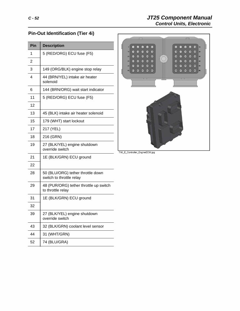
Pin-Out Identification (Tier 4i)
Pin Description
1 5 (RED/ORG) ECU fuse (F5)
2
3 149 (ORG/BLK) engine stop relay
4 44 (BRN/YEL) intake air heater solenoid
6 144 (BRN/ORG) wait start indicator
11 5 (RED/ORG) ECU fuse (F5)
12
13 45 (BLK) intake air heater solenoid
15 179 (WHT) start lockout
17 217 (YEL)
18 216 (GRN)
19 27 (BLK/YEL) engine shutdown override switch
21 1E (BLK/GRN) ECU ground
22
28 50 (BLU/ORG) tether throttle down switch to throttle relay
29 48 (PUR/ORG) tether throttle up switch to throttle relay
31 1E (BLK/GRN) ECU ground
32
39 27 (BLK/YEL) engine shutdown override switch
43 32 (BLK/GRN) coolant level sensor
44 31 (WHT/GRN)
52 74 (BLU/GRA)
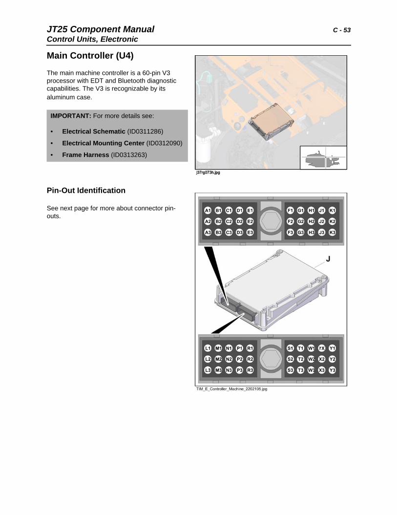
JT25 Component Manual C - 53Control Units, Electronic
Main Controller (U4)
The main machine controller is a 60-pin V3 processor with EDT and Bluetooth diagnostic capabilities. The V3 is recognizable by its aluminum case.
Pin-Out Identification
See next page for more about connector pin-outs.
IMPORTANT: For more details see:
• Electrical Schematic (ID0311286)
• Electrical Mounting Center (ID0312090)
• Frame Harness (ID0313263)
C - 54 JT25 Component ManualControl Units, Electronic
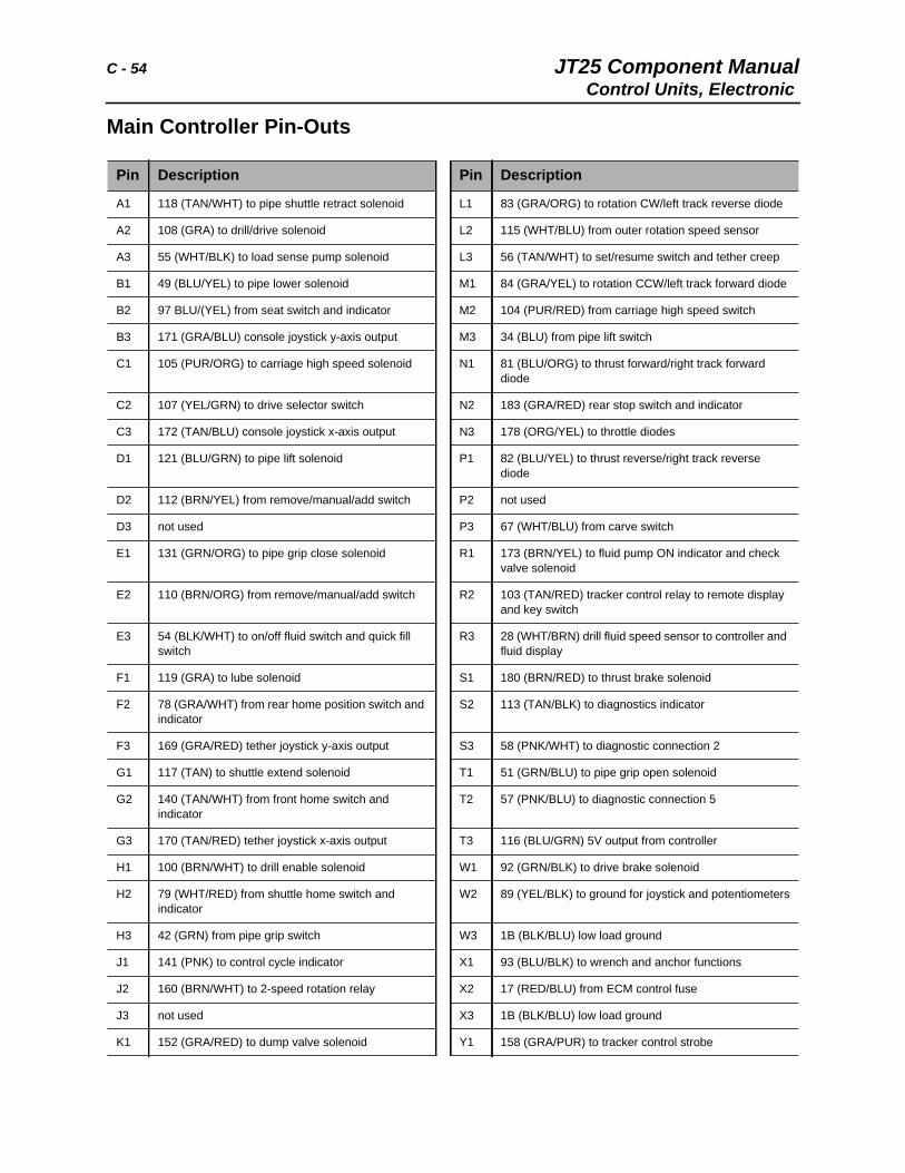
Main Controller Pin-Outs
Pin Description Pin Description
A1 118 (TAN/WHT) to pipe shuttle retract solenoid L1 83 (GRA/ORG) to rotation CW/left track reverse diode
A2 108 (GRA) to drill/drive solenoid L2 115 (WHT/BLU) from outer rotation speed sensor
A3 55 (WHT/BLK) to load sense pump solenoid L3 56 (TAN/WHT) to set/resume switch and tether creep
B1 49 (BLU/YEL) to pipe lower solenoid M1 84 (GRA/YEL) to rotation CCW/left track forward diode
B2 97 BLU/(YEL) from seat switch and indicator M2 104 (PUR/RED) from carriage high speed switch
B3 171 (GRA/BLU) console joystick y-axis output M3 34 (BLU) from pipe lift switch
C1 105 (PUR/ORG) to carriage high speed solenoid N1 81 (BLU/ORG) to thrust forward/right track forward diode
C2 107 (YEL/GRN) to drive selector switch N2 183 (GRA/RED) rear stop switch and indicator
C3 172 (TAN/BLU) console joystick x-axis output N3 178 (ORG/YEL) to throttle diodes
D1 121 (BLU/GRN) to pipe lift solenoid P1 82 (BLU/YEL) to thrust reverse/right track reverse diode
D2 112 (BRN/YEL) from remove/manual/add switch P2 not used
D3 not used P3 67 (WHT/BLU) from carve switch
E1 131 (GRN/ORG) to pipe grip close solenoid R1 173 (BRN/YEL) to fluid pump ON indicator and check valve solenoid
E2 110 (BRN/ORG) from remove/manual/add switch R2 103 (TAN/RED) tracker control relay to remote display and key switch
E3 54 (BLK/WHT) to on/off fluid switch and quick fill switch
R3 28 (WHT/BRN) drill fluid speed sensor to controller and fluid display
F1 119 (GRA) to lube solenoid S1 180 (BRN/RED) to thrust brake solenoid
F2 78 (GRA/WHT) from rear home position switch and indicator
S2 113 (TAN/BLK) to diagnostics indicator
F3 169 (GRA/RED) tether joystick y-axis output S3 58 (PNK/WHT) to diagnostic connection 2
G1 117 (TAN) to shuttle extend solenoid T1 51 (GRN/BLU) to pipe grip open solenoid
G2 140 (TAN/WHT) from front home switch and indicator
T2 57 (PNK/BLU) to diagnostic connection 5
G3 170 (TAN/RED) tether joystick x-axis output T3 116 (BLU/GRN) 5V output from controller
H1 100 (BRN/WHT) to drill enable solenoid W1 92 (GRN/BLK) to drive brake solenoid
H2 79 (WHT/RED) from shuttle home switch and indicator
W2 89 (YEL/BLK) to ground for joystick and potentiometers
H3 42 (GRN) from pipe grip switch W3 1B (BLK/BLU) low load ground
J1 141 (PNK) to control cycle indicator X1 93 (BLU/BLK) to wrench and anchor functions
J2 160 (BRN/WHT) to 2-speed rotation relay X2 17 (RED/BLU) from ECM control fuse
J3 not used X3 1B (BLK/BLU) low load ground
K1 152 (GRA/RED) to dump valve solenoid Y1 158 (GRA/PUR) to tracker control strobe
JT25 Component Manual C - 55Control Units, Electronic
K2 114 (WHT/YEL) from outer rotation speed sensor Y2 16 (RED/GRN) from ECM output fuse
K3 29 (TAN) from pipe shuttle switch Y3
Pin Description Pin Description
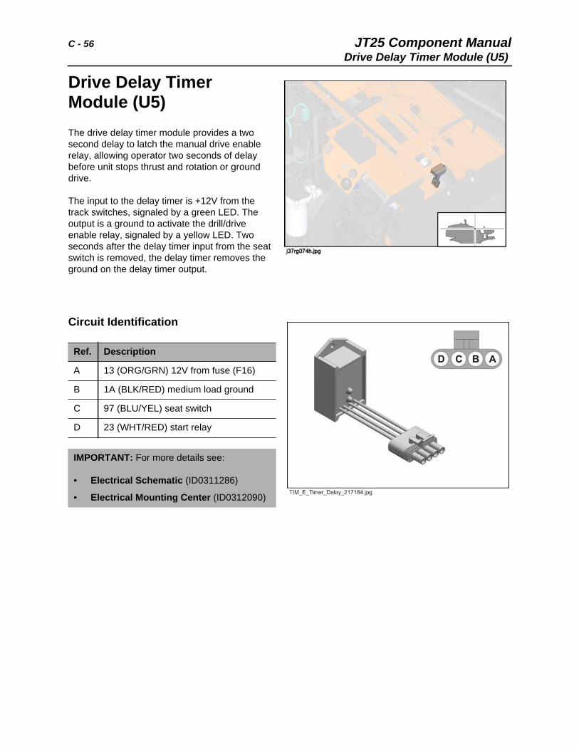
C - 56 JT25 Component ManualDrive Delay Timer Module (U5)
Drive Delay Timer Module (U5)The drive delay timer module provides a two second delay to latch the manual drive enable relay, allowing operator two seconds of delay before unit stops thrust and rotation or ground drive.
The input to the delay timer is +12V from the track switches, signaled by a green LED. The output is a ground to activate the drill/drive enable relay, signaled by a yellow LED. Two seconds after the delay timer input from the seat switch is removed, the delay timer removes the ground on the delay timer output.
Circuit Identification
Ref. Description
A 13 (ORG/GRN) 12V from fuse (F16)
B 1A (BLK/RED) medium load ground
C 97 (BLU/YEL) seat switch
D 23 (WHT/RED) start relay
IMPORTANT: For more details see:
• Electrical Schematic (ID0311286)
• Electrical Mounting Center (ID0312090)
JT25 Component Manual C - 57Current Transformer Coil (T1)
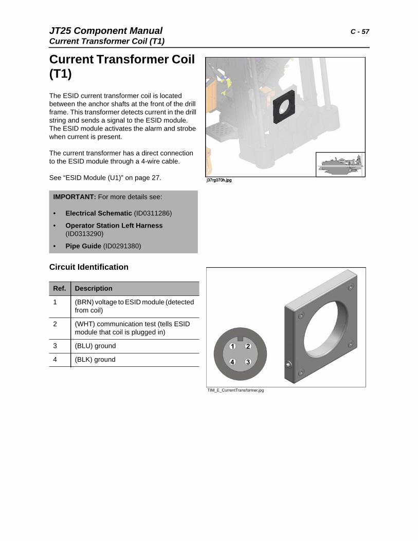
Current Transformer Coil (T1) The ESID current transformer coil is located between the anchor shafts at the front of the drill frame. This transformer detects current in the drill string and sends a signal to the ESID module. The ESID module activates the alarm and strobe when current is present.
The current transformer has a direct connection to the ESID module through a 4-wire cable.
See “ESID Module (U1)” on page 27.
Circuit Identification
IMPORTANT: For more details see:
• Electrical Schematic (ID0311286)
• Operator Station Left Harness (ID0313290)
• Pipe Guide (ID0291380)
Ref. Description
1 (BRN) voltage to ESID module (detected from coil)
2 (WHT) communication test (tells ESID module that coil is plugged in)
3 (BLU) ground
4 (BLK) ground
C - 58 JT25 Component ManualCylinders, Hydraulic
Cylinders, Hydraulic
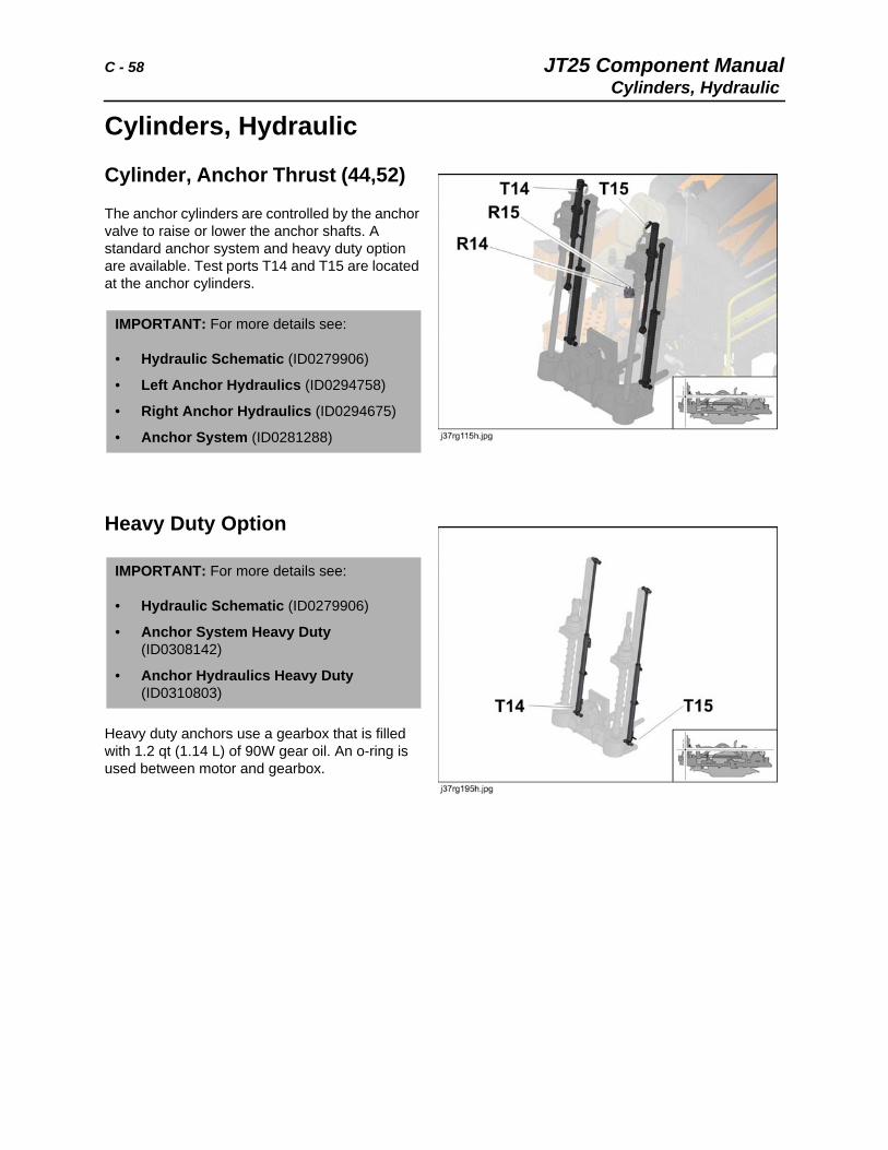
Cylinder, Anchor Thrust (44,52)
The anchor cylinders are controlled by the anchor valve to raise or lower the anchor shafts. A standard anchor system and heavy duty option are available. Test ports T14 and T15 are located at the anchor cylinders.
Heavy Duty Option
Heavy duty anchors use a gearbox that is filled with 1.2 qt (1.14 L) of 90W gear oil. An o-ring is used between motor and gearbox.
IMPORTANT: For more details see:
• Hydraulic Schematic (ID0279906)
• Left Anchor Hydraulics (ID0294758)
• Right Anchor Hydraulics (ID0294675)
• Anchor System (ID0281288)
IMPORTANT: For more details see:
• Hydraulic Schematic (ID0279906)
• Anchor System Heavy Duty (ID0308142)
• Anchor Hydraulics Heavy Duty (ID0310803)
JT25 Component Manual C - 59Cylinders, Hydraulic
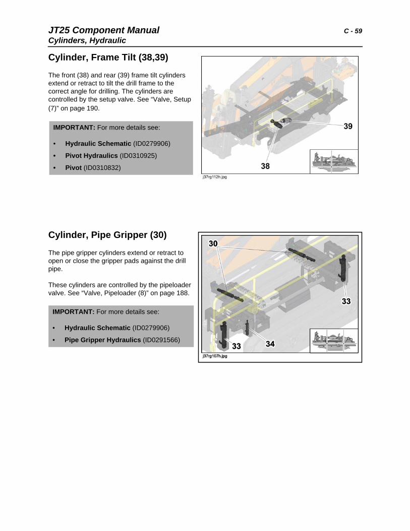
Cylinder, Frame Tilt (38,39)
The front (38) and rear (39) frame tilt cylinders extend or retract to tilt the drill frame to the correct angle for drilling. The cylinders are controlled by the setup valve. See “Valve, Setup (7)” on page 190.
Cylinder, Pipe Gripper (30)
The pipe gripper cylinders extend or retract to open or close the gripper pads against the drill pipe.
These cylinders are controlled by the pipeloader valve. See “Valve, Pipeloader (8)” on page 188.
IMPORTANT: For more details see:
• Hydraulic Schematic (ID0279906)
• Pivot Hydraulics (ID0310925)
• Pivot (ID0310832)
IMPORTANT: For more details see:
• Hydraulic Schematic (ID0279906)
• Pipe Gripper Hydraulics (ID0291566)
C - 60 JT25 Component ManualCylinders, Hydraulic
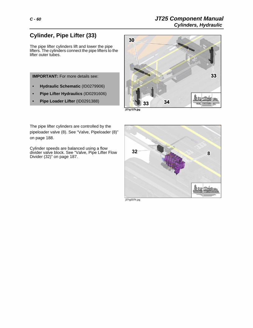
Cylinder, Pipe Lifter (33)
The pipe lifter cylinders lift and lower the pipe lifters. The cylinders connect the pipe lifters to the lifter outer tubes.
The pipe lifter cylinders are controlled by the pipeloader valve (8). See “Valve, Pipeloader (8)” on page 188.
Cylinder speeds are balanced using a flow divider valve block. See “Valve, Pipe Lifter Flow Divider (32)” on page 187.
IMPORTANT: For more details see:
• Hydraulic Schematic (ID0279906)
• Pipe Lifter Hydraulics (ID0291606)
• Pipe Loader Lifter (ID0291388)
JT25 Component Manual C - 61Cylinders, Hydraulic
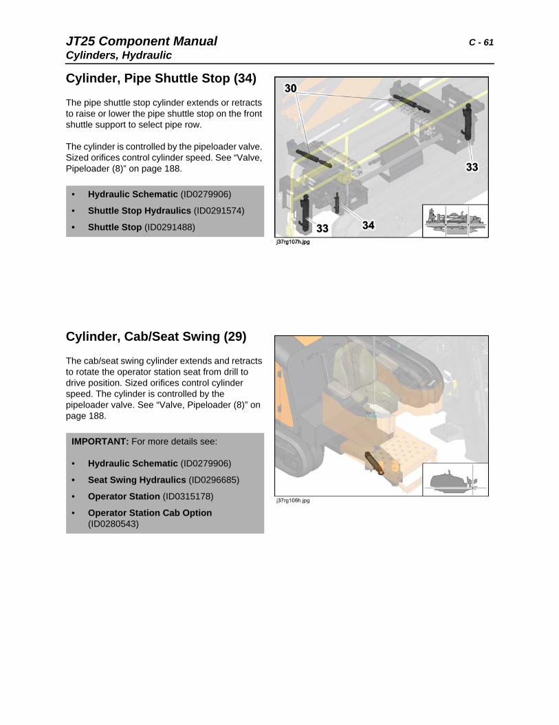
Cylinder, Pipe Shuttle Stop (34)
The pipe shuttle stop cylinder extends or retracts to raise or lower the pipe shuttle stop on the front shuttle support to select pipe row.
The cylinder is controlled by the pipeloader valve. Sized orifices control cylinder speed. See “Valve, Pipeloader (8)” on page 188.
Cylinder, Cab/Seat Swing (29)
The cab/seat swing cylinder extends and retracts to rotate the operator station seat from drill to drive position. Sized orifices control cylinder speed. The cylinder is controlled by the pipeloader valve. See “Valve, Pipeloader (8)” on page 188.
• Hydraulic Schematic (ID0279906)
• Shuttle Stop Hydraulics (ID0291574)
• Shuttle Stop (ID0291488)
IMPORTANT: For more details see:
• Hydraulic Schematic (ID0279906)
• Seat Swing Hydraulics (ID0296685)
• Operator Station (ID0315178)
• Operator Station Cab Option (ID0280543)
C - 62 JT25 Component ManualCylinders, Hydraulic
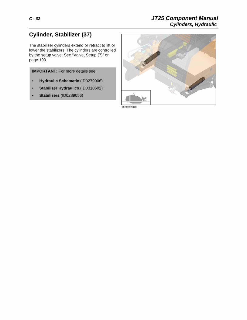
Cylinder, Stabilizer (37)
The stabilizer cylinders extend or retract to lift or lower the stabilizers. The cylinders are controlled by the setup valve. See “Valve, Setup (7)” on page 190.
IMPORTANT: For more details see:
• Hydraulic Schematic (ID0279906)
• Stabilizer Hydraulics (ID0310602)
• Stabilizers (ID0289056)
JT25 Component Manual C - 63Cylinders, Hydraulic
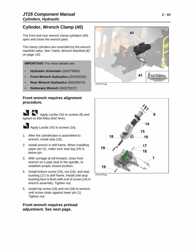
Cylinder, Wrench Clamp (40)
The front and rear wrench clamp cylinders (40) open and close the wrench jaws.
The clamp cylinders are controlled by the wrench manifold valve. See “Valve, Wrench Manifold (6)” on page 192.
Front wrench requires alignment procedure.
Apply Loctite 242 to screws (8) and tighten to 400 ft•lbs (542 N•m).
Apply Loctite 242 to screws (16).
1. After the cylinder/jaw is assembled to wrench, install stop (15).
2. Install wrench in drill frame. When installing upper pin (1), make sure stop leg (15) is below pin.
3. With carriage at full forward, close front wrench on a pipe stub in the spindle, to establish proper closed position.
4. Install bottom screw (19), nut (18), and stop bushing (17) to drill frame. Install until stop bushing face is flush with end of screw (14) in wrench assembly. Tighten nut.
5. Install top screw (19) and nut (18) to wrench, until screw stops against lower pin (1). Tighten nut.
Front wrench requires preload adjustment. See next page.
IMPORTANT: For more details see:
• Hydraulic Schematic (ID0279906)
• Front Wrench Hydraulics (ID0293330)
• Rear Wrench Hydraulics (ID0293276)
• Stationary Wrench (ID0279237)
C - 64 JT25 Component ManualCylinders, Hydraulic
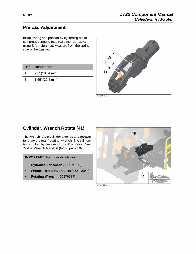
Preload Adjustment
Install spring and preload by tightening nut to compress spring to required dimension at A, using B for reference. Measure from the spring side of the washer.
Cylinder, Wrench Rotate (41)
The wrench rotate cylinder extends and retracts to rotate the rear (rotating) wrench. The cylinder is controlled by the wrench manifold valve. See “Valve, Wrench Manifold (6)” on page 192.
Ref. Description
A 7.3” (185.4 mm)
B 1.55” (39.4 mm)
IMPORTANT: For more details see:
• Hydraulic Schematic (ID0279906)
• Wrench Rotate Hydraulics (ID0293349)
• Rotating Wrench (ID0279987)
JT25 Component Manual D - 65Cylinders, Hydraulic
D
Chapter Contents
Diagnostic Connections. . . . . . . . . . . . . . . . . . . . . 66
• CAN Connection . . . . . . . . . . . . . . . . . . . . . . . . . . . . . . . . . . . . . . . . . . 66
• EDT Connection . . . . . . . . . . . . . . . . . . . . . . . . . . . . . . . . . . . . . . . . . . 67
Diodes . . . . . . . . . . . . . . . . . . . . . . . . . . . . . . . . . . . 68
• Alternator Diode Resistor . . . . . . . . . . . . . . . . . . . . . . . . . . See Alternator
• Diode Pack, Operator Station Left Harness . . . . . . . . . . . . . . . . . . . . . 68
• Diode Block, Operator Station Right Harness. . . . . . . . . . . . . . . . . . . . 69
• Diodes, Relay Panel . . . . . . . . . . . . . See Fuse, Diode and Relay Panels
D - 66 JT25 Component ManualDiagnostic Connections
Diagnostic Connections
CAN Diagnostic Connection (J3)
The CAN J1939 diagnostic connection is an access point for electronic diagnostics using laptop or PC connections.
Circuit Identification
IMPORTANT: For more details see:
• Electrical Schematic (ID0311286)
• Frame Harness (ID0281076)
• Electrical Mounting Center (ID0312090)
Ref. Description
A 1B (BLK/BLU) low load ground
B 8 (RED/BRN) 12V from fuse (F14)
C 22 (YEL) CAN-High
D 23 (GRN) CAN-Low
J 151 (TAN/BLK) 12V from fuse (F8)
Troubleshooting Tip: Testing across C and D with both resistors connected should measure 60 Ohm.
JT25 Component Manual D - 67Diagnostic Connections
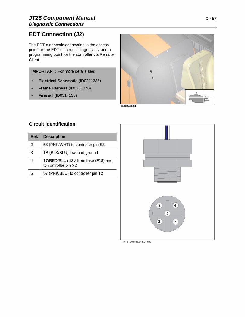
EDT Connection (J2)
The EDT diagnostic connection is the access point for the EDT electronic diagnostics, and a programming point for the controller via Remote Client.
Circuit Identification
IMPORTANT: For more details see:
• Electrical Schematic (ID0311286)
• Frame Harness (ID0281076)
• Firewall (ID0314530)
Ref. Description
2 58 (PNK/WHT) to controller pin S3
3 1B (BLK/BLU) low load ground
4 17(RED/BLU) 12V from fuse (F18) and to controller pin X2
5 57 (PNK/BLU) to controller pin T2
D - 68 JT25 Component ManualDiodes
Diodes
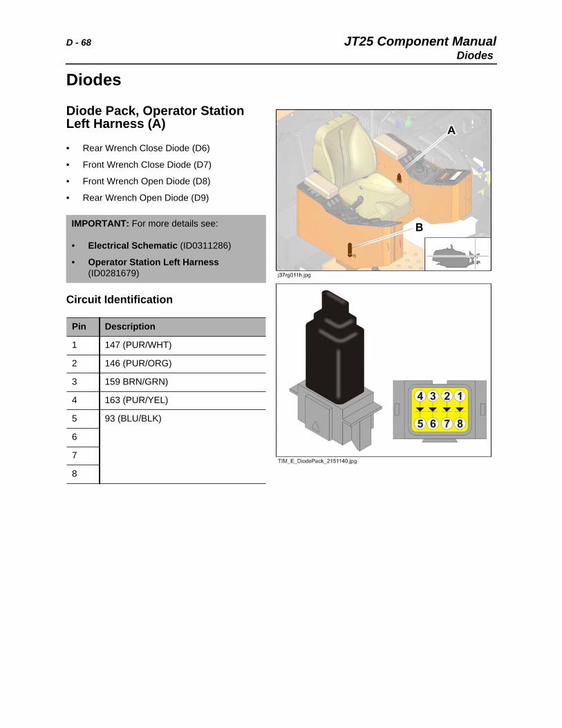
Diode Pack, Operator Station Left Harness (A)
• Rear Wrench Close Diode (D6)
• Front Wrench Close Diode (D7)
• Front Wrench Open Diode (D8)
• Rear Wrench Open Diode (D9)
Circuit Identification
IMPORTANT: For more details see:
• Electrical Schematic (ID0311286)
• Operator Station Left Harness (ID0281679)
Pin Description
1 147 (PUR/WHT)
2 146 (PUR/ORG)
3 159 BRN/GRN)
4 163 (PUR/YEL)
5 93 (BLU/BLK)
6
7
8
JT25 Component Manual D - 69
Diode Pack, Operator Station Right Harness (B)
• Pipeloader Functions Diode (D5)
• Anchor Switch Diode (D10)
Circuit Identification
IMPORTANT: For more details see:
• Electrical Schematic (ID0311286)
• Operator Station Right Harness (ID0281876)
Pin Description
A 106 (PNK)
B 116 (BLU/GRN)
C
D
D - 70 JT25 Component Manual
Diode Pack, Rear Hood Contactor (D13, D14)
Circuit Identification
IMPORTANT: For more details see:
• Electrical Schematic (ID0311286)
• Frame Harness (ID0281076)
Pin Description
1 76 (TAN/ORG) contactor to switch
2 1 (BLK) high load ground
JT25 Component Manual D - 71
DWA Load Sense Pump Diode, Inline (D15)
Circuit Identification
IMPORTANT: For more details see:
• Electrical Schematic (ID0311286)
• Frame Harness (ID0281076)
Pin Description
1 1A (BLK/RED) medium load ground
2 55 (WHT/BLK) to pump solenoiod

D - 72 JT25 Component Manual
JT25 Component Manual E - 73
E
Chapter Contents
Electrical Mounting Center . . . . . . . . . . . . . . . . . . 74
Engine, Tier 3 . . . . . . . . . . . . . . . . . . . . . . . . . . . . . 75
Engine, Tier 4i . . . . . . . . . . . . . . . . . . . . . . . . . . . . . 76
• Engine Crankcase Breather, Tier 4i . . . . . . . . . . . . . . . . . . . . . . . . . . . 77
• Charge Air Temperature Sensor, Tier 4i . . . . . . . . . . . . . . . . . . . . . . . . 78
E - 74 JT25 Component ManualElectrical Mounting Center
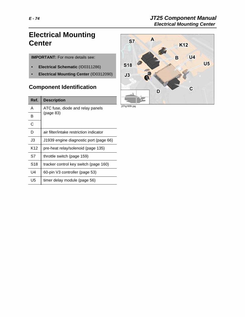
Electrical Mounting Center
Component Identification
IMPORTANT: For more details see:
• Electrical Schematic (ID0311286)
• Electrical Mounting Center (ID0312090)
Ref. Description
A ATC fuse, diode and relay panels (page 83)
B
C
D air filter/intake restriction indicator
J3 J1939 engine diagnostic port (page 66)
K12 pre-heat relay/solenoid (page 135)
S7 throttle switch (page 159)
S18 tracker control key switch (page 160)
U4 60-pin V3 controller (page 53)
U5 timer delay module (page 56)
JT25 Component Manual E - 75Engine, Tier 3
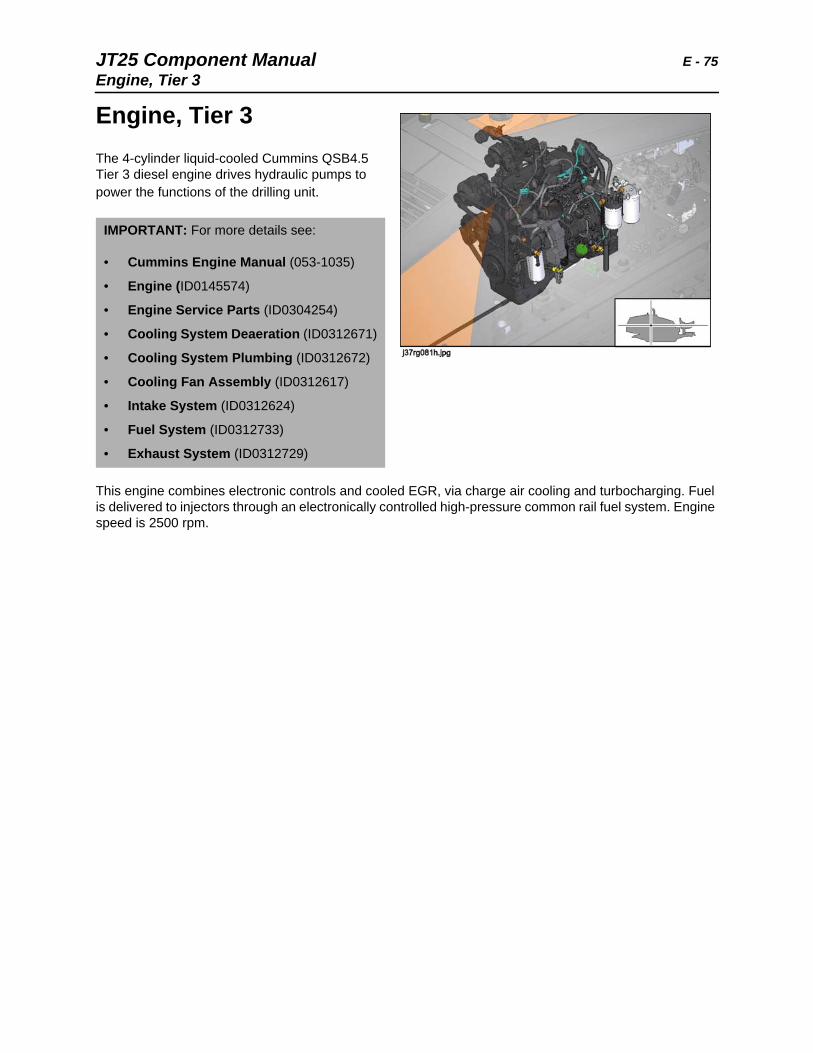
Engine, Tier 3
The 4-cylinder liquid-cooled Cummins QSB4.5 Tier 3 diesel engine drives hydraulic pumps to power the functions of the drilling unit.
This engine combines electronic controls and cooled EGR, via charge air cooling and turbocharging. Fuel is delivered to injectors through an electronically controlled high-pressure common rail fuel system. Engine speed is 2500 rpm.
IMPORTANT: For more details see:
• Cummins Engine Manual (053-1035)
• Engine (ID0145574)
• Engine Service Parts (ID0304254)
• Cooling System Deaeration (ID0312671)
• Cooling System Plumbing (ID0312672)
• Cooling Fan Assembly (ID0312617)
• Intake System (ID0312624)
• Fuel System (ID0312733)
• Exhaust System (ID0312729)
E - 76 JT25 Component ManualEngine, Tier 4i
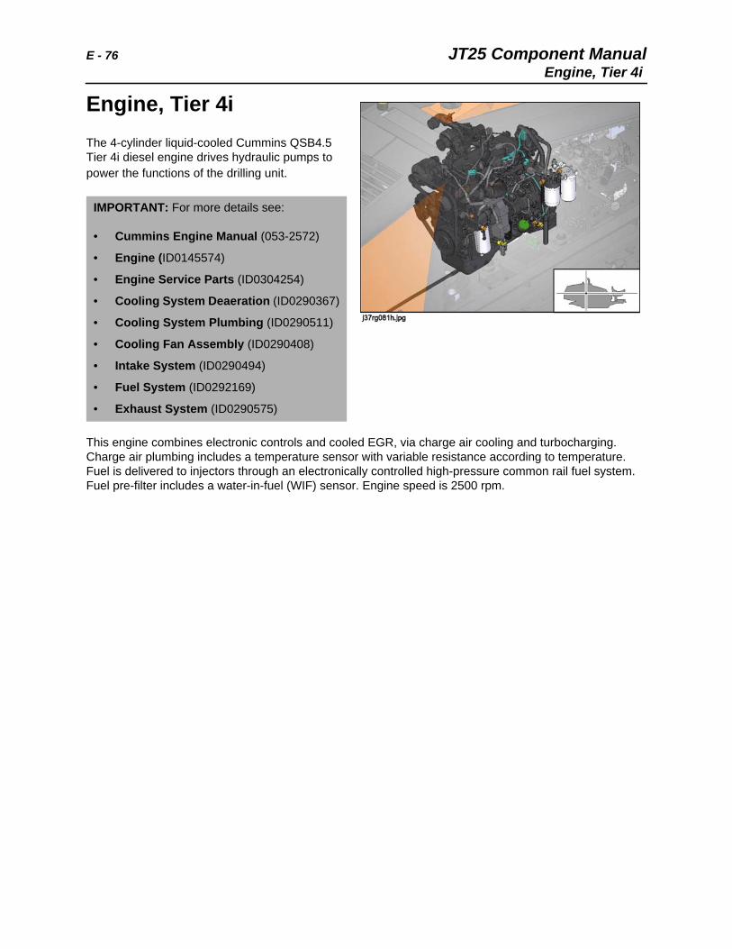
Engine, Tier 4i The 4-cylinder liquid-cooled Cummins QSB4.5 Tier 4i diesel engine drives hydraulic pumps to power the functions of the drilling unit.
This engine combines electronic controls and cooled EGR, via charge air cooling and turbocharging. Charge air plumbing includes a temperature sensor with variable resistance according to temperature. Fuel is delivered to injectors through an electronically controlled high-pressure common rail fuel system. Fuel pre-filter includes a water-in-fuel (WIF) sensor. Engine speed is 2500 rpm.
IMPORTANT: For more details see:
• Cummins Engine Manual (053-2572)
• Engine (ID0145574)
• Engine Service Parts (ID0304254)
• Cooling System Deaeration (ID0290367)
• Cooling System Plumbing (ID0290511)
• Cooling Fan Assembly (ID0290408)
• Intake System (ID0290494)
• Fuel System (ID0292169)
• Exhaust System (ID0290575)
JT25 Component Manual E - 77
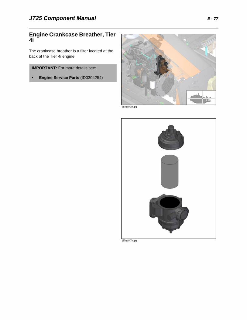
Engine Crankcase Breather, Tier 4i
The crankcase breather is a filter located at the back of the Tier 4i engine.
IMPORTANT: For more details see:
• Engine Service Parts (ID0304254)
E - 78 JT25 Component Manual
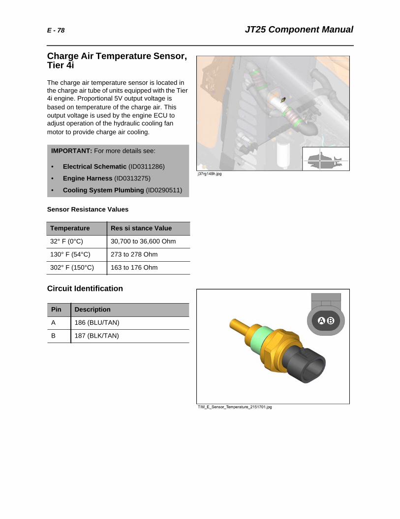
Charge Air Temperature Sensor, Tier 4i
The charge air temperature sensor is located in the charge air tube of units equipped with the Tier 4i engine. Proportional 5V output voltage is based on temperature of the charge air. This output voltage is used by the engine ECU to adjust operation of the hydraulic cooling fan motor to provide charge air cooling.
Sensor Resistance Values
Circuit Identification
IMPORTANT: For more details see:
• Electrical Schematic (ID0311286)
• Engine Harness (ID0313275)
• Cooling System Plumbing (ID0290511)
Temperature Res si stance Value
32° F (0°C) 30,700 to 36,600 Ohm
130° F (54°C) 273 to 278 Ohm
302° F (150°C) 163 to 176 Ohm
Pin Description
A 186 (BLU/TAN)
B 187 (BLK/TAN)
JT25 Component Manual F - 79
F
Chapter Contents
Fan, Hydraulic Cooling. . . . . . . . . . . . . . . . . . . . . . 80
Filter, Fuel . . . . . .See Service in Operator’s Manual
Filter, Hydraulic Fluid . . . . . . . . . . . . . . . . . . . . . . . 81
Fuel Tank . . . . . . . . . . . . . . . . . . . . . . . . . . . See Tank
Fuse, Diode and Relay Panels . . . . . . . . . . . . . . . . 83
• BK/AMI Fuses . . . . . . . . . . . . . . . . . . . . . . . . . . . . . . . . . . . . . . . . . . . . 83
• ATC Fuse, Diode and Relay Panels . . . . . . . . . . . . . . . . . . . . . . . . . . . 84
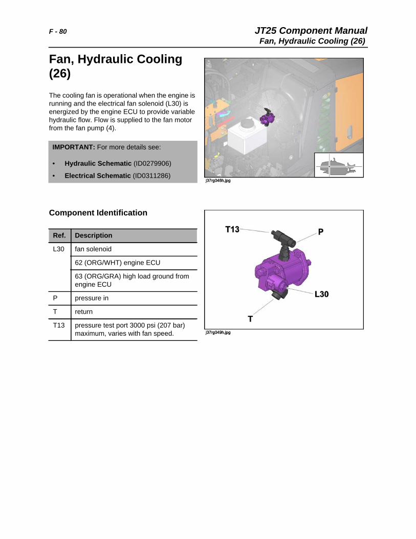
F - 80 JT25 Component ManualFan, Hydraulic Cooling (26)
Fan, Hydraulic Cooling (26) The cooling fan is operational when the engine is running and the electrical fan solenoid (L30) is energized by the engine ECU to provide variable hydraulic flow. Flow is supplied to the fan motor from the fan pump (4).
Component Identification
IMPORTANT: For more details see:
• Hydraulic Schematic (ID0279906)
• Electrical Schematic (ID0311286)
Ref. Description
L30 fan solenoid
62 (ORG/WHT) engine ECU
63 (ORG/GRA) high load ground from engine ECU
P pressure in
T return
T13 pressure test port 3000 psi (207 bar) maximum, varies with fan speed.
JT25 Component Manual F - 81Filter, Hydraulic Fluid (25)
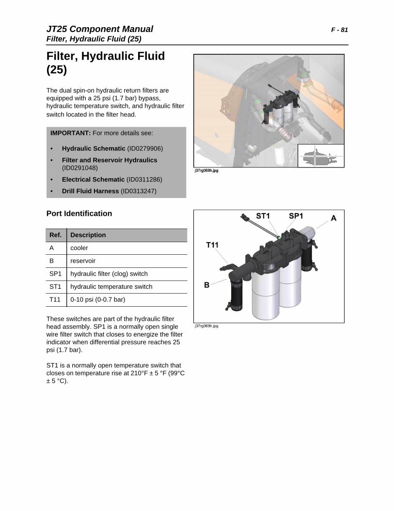
Filter, Hydraulic Fluid (25)The dual spin-on hydraulic return filters are equipped with a 25 psi (1.7 bar) bypass, hydraulic temperature switch, and hydraulic filter switch located in the filter head.
Port Identification
These switches are part of the hydraulic filter head assembly. SP1 is a normally open single wire filter switch that closes to energize the filter indicator when differential pressure reaches 25 psi (1.7 bar).
ST1 is a normally open temperature switch that closes on temperature rise at 210°F ± 5 °F (99°C ± 5 °C).
IMPORTANT: For more details see:
• Hydraulic Schematic (ID0279906)
• Filter and Reservoir Hydraulics (ID0291048)
• Electrical Schematic (ID0311286)
• Drill Fluid Harness (ID0313247)
Ref. Description
A cooler
B reservoir
SP1 hydraulic filter (clog) switch
ST1 hydraulic temperature switch
T11 0-10 psi (0-0.7 bar)
F - 82 JT25 Component ManualFilter, Hydraulic Fluid (25)
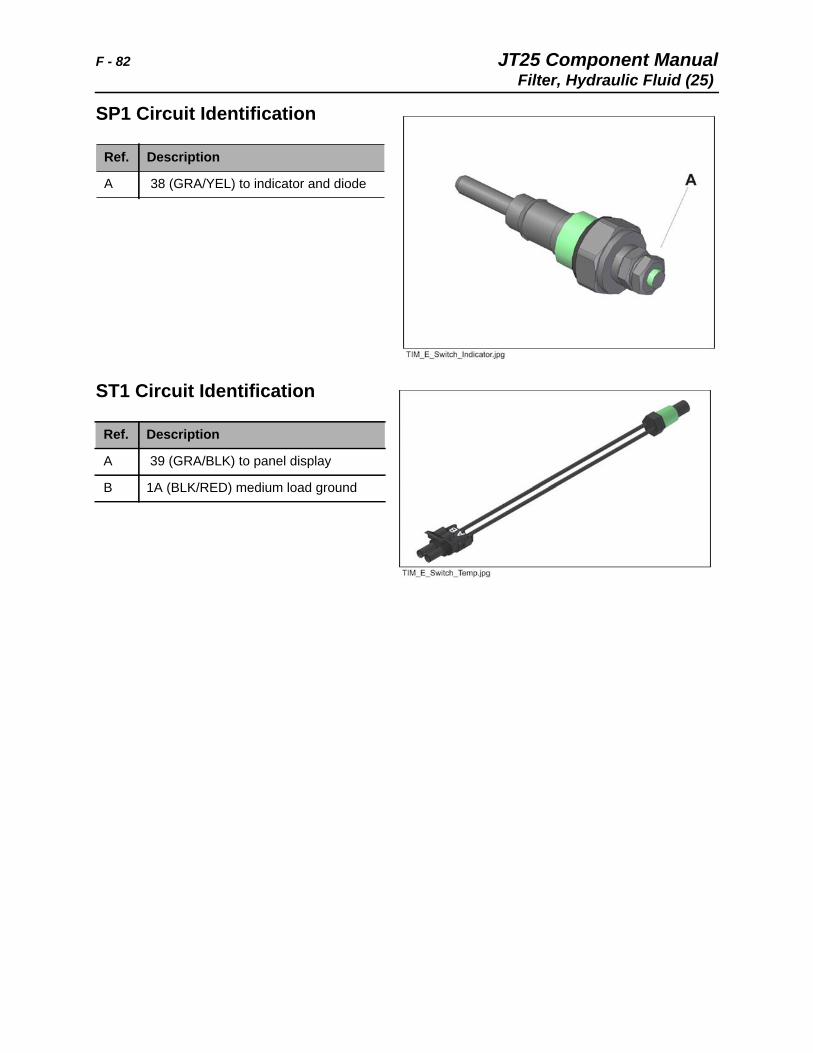
SP1 Circuit Identification
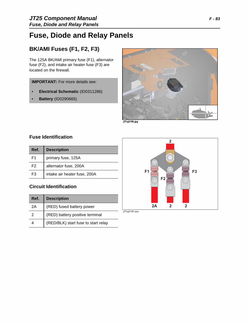
ST1 Circuit Identification
Ref. Description
A 38 (GRA/YEL) to indicator and diode
Ref. Description
A 39 (GRA/BLK) to panel display
B 1A (BLK/RED) medium load ground
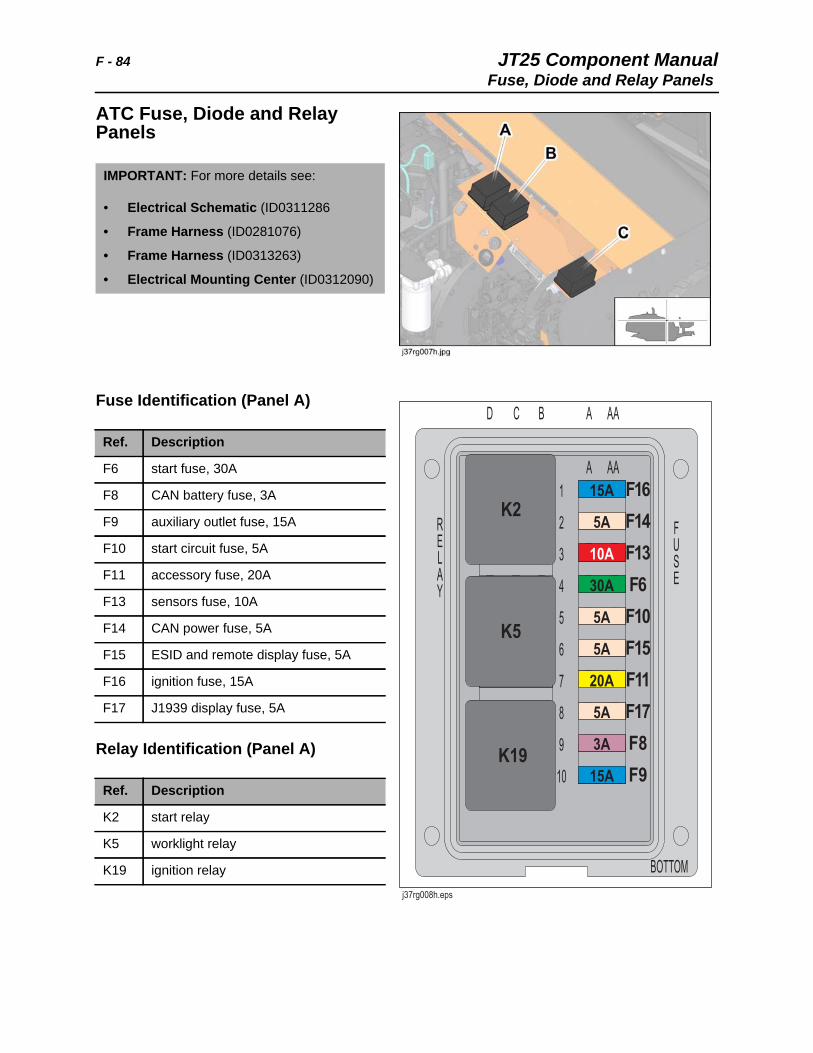
JT25 Component Manual F - 83Fuse, Diode and Relay Panels
Fuse, Diode and Relay Panels
BK/AMI Fuses (F1, F2, F3)
The 125A BK/AMI primary fuse (F1), alternator fuse (F2), and intake air heater fuse (F3) are located on the firewall.
Fuse Identification
Circuit Identification
IMPORTANT: For more details see:
• Electrical Schematic (ID0311286)
• Battery (ID0290665)
Ref. Description
F1 primary fuse, 125A
F2 alternator fuse, 200A
F3 intake air heater fuse, 200A
Ref. Description
2A (RED) fused battery power
2 (RED) battery positive terminal
4 (RED/BLK) start fuse to start relay
F - 84 JT25 Component ManualFuse, Diode and Relay Panels
ATC Fuse, Diode and Relay Panels
Fuse Identification (Panel A)
Relay Identification (Panel A)
IMPORTANT: For more details see:
• Electrical Schematic (ID0311286
• Frame Harness (ID0281076)
• Frame Harness (ID0313263)
• Electrical Mounting Center (ID0312090)
Ref. Description
F6 start fuse, 30A
F8 CAN battery fuse, 3A
F9 auxiliary outlet fuse, 15A
F10 start circuit fuse, 5A
F11 accessory fuse, 20A
F13 sensors fuse, 10A
F14 CAN power fuse, 5A
F15 ESID and remote display fuse, 5A
F16 ignition fuse, 15A
F17 J1939 display fuse, 5A
Ref. Description
K2 start relay
K5 worklight relay
K19 ignition relay
JT25 Component Manual F - 85Fuse, Diode and Relay Panels
Fuse/Diode Identification (Panel B)
Relay Identification (Panel B)
Ref. Description
D1 throttle switch diode
D2 throttle relay diode
F4 main fuse, 10A
F5 ECM fuse, 30A
F7 worklight fuse, 20A
F12 ECM output fuse, 20A
F18 ECM control fuse, 3A
F19 FMS fuse, 3A
Ref. Description
K1 accessory cutout relay
K8 throttle relay
K9 track override enable relay
K15 start lockout relay
K20 accessory relay
F - 86 JT25 Component ManualFuse, Diode and Relay Panels
Fuse/Diode Identification (Panel C)
Relay Identification (Panel C)
Rear Hood Fuse
Ref. Description
D3 manual drive relay diode
D4 drive brake solenoid diode
D11 CCW rotation limit diode
D12 CCW rotation limit diode
Ref. Description
K7 FMS relay, optional
K11 2-speed rotation relay
K13 front wrench relay
K14 rear wrench relay
K17 CCW rotation limit relay
Ref. Description
F25 rear hood fuse, 30A
JT25 Component Manual F - 87Fuse, Diode and Relay Panels
Heavy Duty Cab Fuse
Cab option units only.
Ref. Description
F20 cab fuse, 125A
F - 88 JT25 Component ManualFuse, Diode and Relay Panels
Cab Option, Fuse Panel
Cab option units only.
Fuse Identification
Ref. Description
F21 light fuse, 20A
F22 wiper fuse, 15A
F23 condenser fuse, 30A
F24 blower fuse, 30A
JT25 Component Manual G - 89
G
Gauges. . . . . . . . . . . . . . . . . . . . . . .See Left Console
Gearboxes . . . . . . . . . . . . . . . . . . . . . . . . . . . . . . . . 90
• JT Rotation Gearbox . . . . . . . . . . . . . . . . . . . . . . . . . . . . . . . . . . . . . . . 90
• Track Drive Planetary Gearbox. . . . . . . . . . . . . . . . . . . . See Track Motor
G - 90 JT25 Component ManualGearboxes
Gearboxes
JT Rotation Gearbox
The JT rotation gearbox is driven by the radial 2-speed rotation motor, and rotates the spindle clockwise and counter clockwise. Gearbox is filled with 3.35 qt (3.17 L) of 90W gear oil.
IMPORTANT: For more details see:
• Gearbox (ID0286380)
• Spindle Drive (ID0290691)
JT25 Component Manual G - 91Gearboxes
Prepare Housing
1. Clean housing, cover, and all gasket surfaces and bores carefully.
2. Install bearing races into respective bores.
Assemble Gear Train
1. Position spindle output shaft (31) with grooved end facing up.
2. Install bearing (32).
3. Flip shaft over and install gear (1).
4. Install second bearing onto spindle shaft, above gear.
5. Place shaft assembly into housing, grooved end down.
IMPORTANT: Metric bearings are installed in outer bores, and standard bearing is installed in center bore.
IMPORTANT: Check to make sure groove is visible.
G - 92 JT25 Component ManualGearboxes
6. Install bearings (13) on each side of idler gear (2) on center shaft.
7. Install idler assembly into housing to mesh with spindle output shaft gear.
8. Install bearing (6) onto input pinion shaft (3).
9. Flip shaft over and install second bearing.
10. Install speed sensor ring (9) above second bearing.
11. Install pinion shaft assembly into housing.
JT25 Component Manual G - 93Gearboxes
Establish Bearing Preload
1. Measure height of each shaft bearing (race installed) from housing gasket surface (A,B,C). Measure at least two places. Record measurements.
2. On the housing cover, perform similar measurements from gasket surface into each bore, at the bearing shoulder (D,E,F). Measure at least two places. Record measurements.
Note: The difference between the averaged measurements for each housing shaft assembly and each cover bore assembly is the clearance to determine shim thickness.
For example, if the gear assembly measured a height of 3.565” and the cover bore depth measured 3.863”, the clearance is 0.29”, which can be rounded to 0.30” in shim thickness.
G - 94 JT25 Component ManualGearboxes
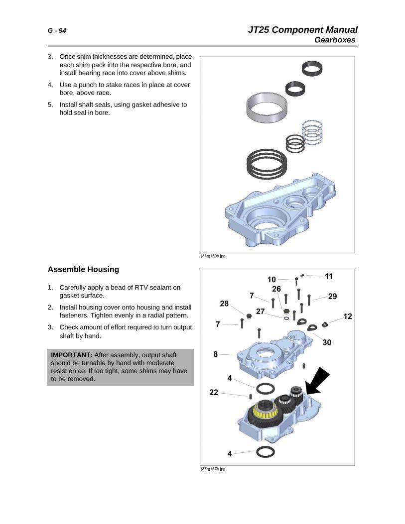
3. Once shim thicknesses are determined, place each shim pack into the respective bore, and install bearing race into cover above shims.
4. Use a punch to stake races in place at cover bore, above race.
5. Install shaft seals, using gasket adhesive to hold seal in bore.
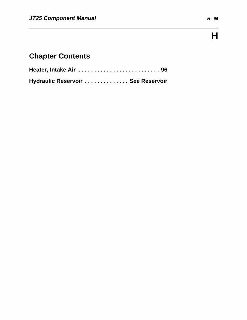
Assemble Housing
1. Carefully apply a bead of RTV sealant on gasket surface.
2. Install housing cover onto housing and install fasteners. Tighten evenly in a radial pattern.
3. Check amount of effort required to turn output shaft by hand.
IMPORTANT: After assembly, output shaft should be turnable by hand with moderate resist en ce. If too tight, some shims may have to be removed.
JT25 Component Manual H - 95
H
Chapter Contents
Heater, Intake Air . . . . . . . . . . . . . . . . . . . . . . . . . . 96
Hydraulic Reservoir . . . . . . . . . . . . . . See Reservoir
H - 96 JT25 Component ManualHeater, Intake Air
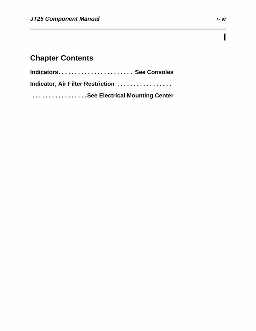
Heater, Intake Air The intake air heater element (not shown) warms the air in the intake manifold to assist starting in low ambient temperatures. The heater relay/solenoid is located on the Electrical Mounting Center, and is energized by output from the engine ECU.
(K12) Relay/Solenoid Circuit Identification
IMPORTANT: For more details see:
• Electrical Schematic (ID0311286)
• Engine Harness (ID0313288)
• Electrical Mounting Center (ID0312090)
Ref. Description
A 2 (RED) 12V from fuse (F3), 200A
B 15 (RED) to heater element
C 44 (BRN/YEL) from engine controller
D 44 (BLK) ground from engine controller
JT25 Component Manual I - 97
I
Chapter Contents
Indicators. . . . . . . . . . . . . . . . . . . . . . . See Consoles
Indicator, Air Filter Restriction . . . . . . . . . . . . . . . . .
. . . . . . . . . . . . . . . . .See Electrical Mounting Center

I - 98 JT25 Component Manual
JT25 Component Manual J, K, L - 99
J, K, L
Chapter Contents
Joystick . . . . . . . . . . . . . . . . . . . . . . . . See Consoles

J, K, L - 100 JT25 Component Manual
JT25 Component Manual M, N, O - 101
M, N, O
Chapter Contents
Manifolds, Hydraulic. . . . . . . . . . . . . . . . . . . . . . . 102
• Charge Pressure Manifold, Carriage. . . . . . . . . . . . . . . . . . . . . . . . . . 102
• Charge Pressure Manifold, Engine Compartment . . . . . . . . . . . . . . . 103
• Drain Manifold . . . . . . . . . . . . . . . . . . . . . . . . . . . . . . . . . . . . . . . . . . . 104
• Drilling Fluid Manifold . . . . . . . . . . . . . . . . . . . . . . . . . . . . . . . . . . . . . 105
• Proportional Manifold . . . . . . . . . . . . . . . . . . . . . . . . . . . . . . . . . . . . . 106
• Spike Relief Manifold . . . . . . . . . . . . . . . . . . . . . . . . . . . . . . . . . . . . . 107
• Wrench Valve Manifold . . . . . . . . . . . . . . . . . . . . . . . . . . . . . . . See Valve
Motors, Electric . . . . . . . . . . . . . . . . . . . . . . . . . . . 108
• Hood Actuator . . . . . . . . . . . . . . . . . . . . . . . . . . . . . . . . . . . . See Actuator
• Washer Motor . . . . . . . . . . . . . . . . . . . . . . . . . . . . . . . . . . . . . . . . . . . 108
• Wiper Motor. . . . . . . . . . . . . . . . . . . . . . . . . . . . . . . . . . . . . . . . . . . . . 109
Motors, Hydraulic . . . . . . . . . . . . . . . . . . . . . . . . . 110
• Air Conditioner Motor . . . . . . . . . . . . . . . . . . . . . . . . . . . . . . . . . . . . . 110
• Anchor Rotation Motor . . . . . . . . . . . . . . . . . . . . . . . . . . . . . . . . . . . . 111
• Cooling Fan Motor. . . . . . . . . . . . . . . . . . . . . . . . . . . . . . . . . . . . . . . . 113
• Drilling Fluid Pump Motor . . . . . . . . . . . . . . . . . . . . . . . . . . . . . . . . . . 114
• Ground Drive Track Motor. . . . . . . . . . . . . . . . . . . . . . . . . . . . . . . . . . 115
• JT Rotation Motor . . . . . . . . . . . . . . . . . . . . . . . . . . . . . . . . . . . . . . . . 116
• Pipe Shuttle Motor. . . . . . . . . . . . . . . . . . . . . . . . . . . . . . . . . . . . . . . . 118
• Thrust, Motor. . . . . . . . . . . . . . . . . . . . . . . . . . . . . . . . . . . . . . . . . . . . 119
M, N, O - 102 JT25 Component ManualManifolds, Hydraulic
Manifolds, Hydraulic
Manifold, Charge Pressure (9)
Charge pressure manifold (9) is one of two charge pressure manifolds in different locations.
Charge pressure manifold (9) is located on the carriage. Pressure from the thrust charge pump is supplied to release the thrust brake and to provide carriage high speed to the thrust motors, depending on solenoid operation.
Measure thrust pump charge pressure at test port (T8) located on the side of the thrust pump. Charge pressure is 350 psi (24 bar).
Measure carriage charge pressure at test port (T17) located on manifold. Charge pressure is 260 psi (18 bar).
Port Identification
IMPORTANT: For more details see:
• Hydraulic Schematic (ID0279906)
• Thrust 2-Speed and Brake Hydraulics (ID0293891)
• Thrust and Rotation Motor Case Drain (ID0290790)
Port Description
1 thrust motor brake
2 thrust motor high speed
L7 thrust brake solenoid
L11 high speed thrust solenoid
P from pump
T drain manifold
T17 carriage charge pressure 260 psi (18 bar)
JT25 Component Manual M, N, O - 103Manifolds, Hydraulic
Manifold, Charge Pressure (10)
Charge pressure manifold (10) is one of two charge pressure manifolds in different locations.
Charge pressure manifold (10) is located on the frame in the engine compartment.
Pressure from the thrust charge pump is supplied to apply the track brake and to provide flow for selecting drill/drive functions, depending on solenoid operation.
Measure charge pressure at test port (T8) located on the side of the thrust pump. Charge pressure is 350 psi (24 bar). Check or set at high idle with no functions operating.
Port Identification
IMPORTANT: For more details see:
• Hydraulic Schematic (ID0279906)
• POR Flushing and Charge Hydraulics (ID0291815)
• Rotation Motor Flushing Hydraulics (ID0290862)
Port Description
1 track brakes
2 drill/drive selector line
L6 track drive brake solenoid
L10 drill/drive selector solenoid
P pressure from thrust charge pump
T to load sense pump hardline to tank
M, N, O - 104 JT25 Component ManualManifolds, Hydraulic
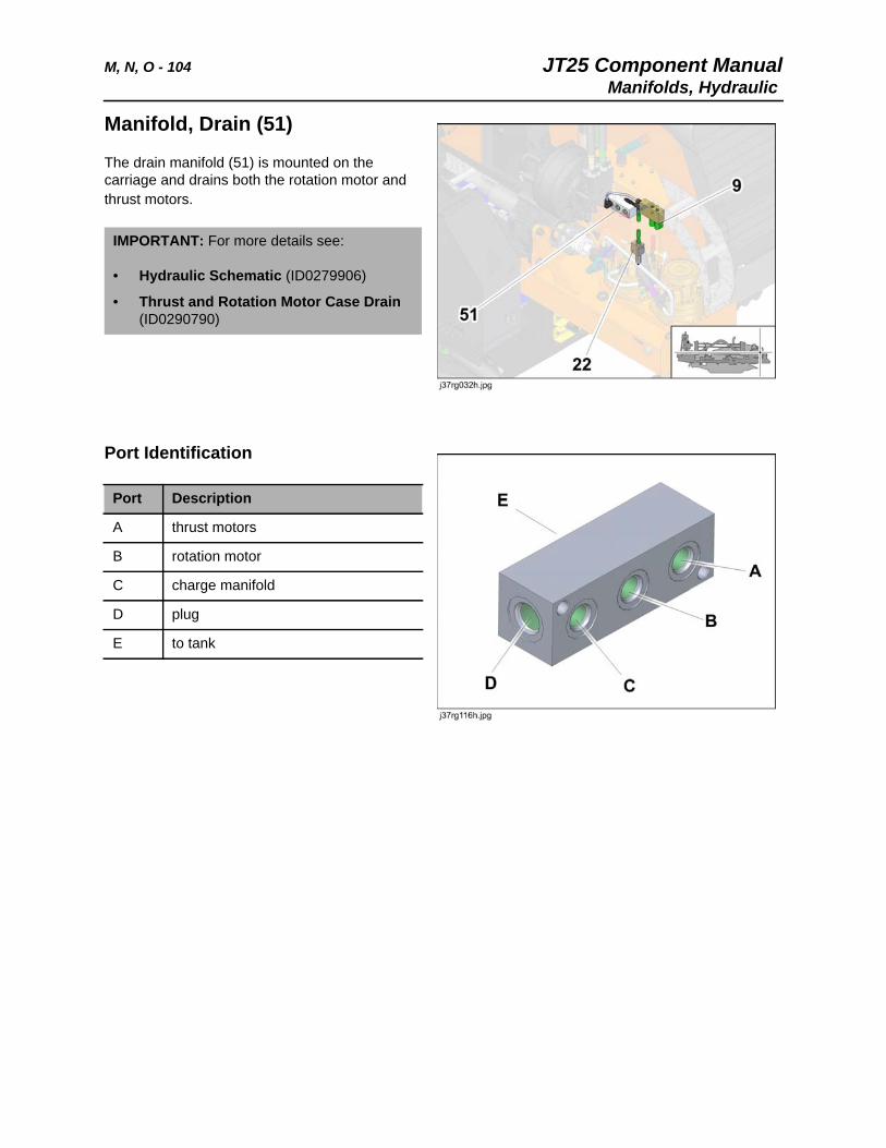
Manifold, Drain (51)
The drain manifold (51) is mounted on the carriage and drains both the rotation motor and thrust motors.
Port Identification
IMPORTANT: For more details see:
• Hydraulic Schematic (ID0279906)
• Thrust and Rotation Motor Case Drain (ID0290790)
Port Description
A thrust motors
B rotation motor
C charge manifold
D plug
E to tank
JT25 Component Manual M, N, O - 105Manifolds, Hydraulic
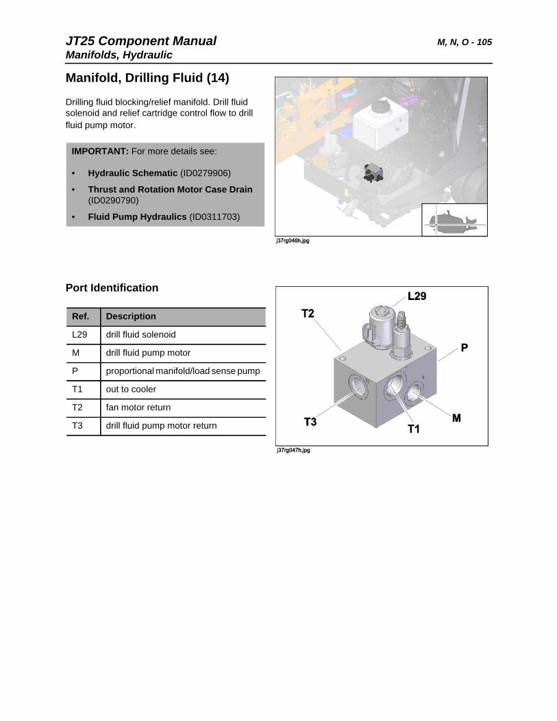
Manifold, Drilling Fluid (14)
Drilling fluid blocking/relief manifold. Drill fluid solenoid and relief cartridge control flow to drill fluid pump motor.
Port Identification
IMPORTANT: For more details see:
• Hydraulic Schematic (ID0279906)
• Thrust and Rotation Motor Case Drain (ID0290790)
• Fluid Pump Hydraulics (ID0311703)
Ref. Description
L29 drill fluid solenoid
M drill fluid pump motor
P proportional manifold/load sense pump
T1 out to cooler
T2 fan motor return
T3 drill fluid pump motor return
M, N, O - 106 JT25 Component ManualManifolds, Hydraulic
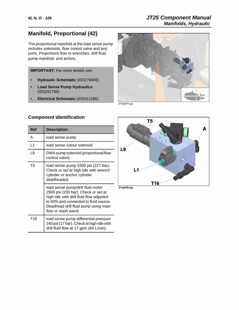
Manifold, Proportional (42)
The proportional manifold at the load sense pump includes solenoids, flow control valve and test ports. Proportions flow to wrenches, drill fluid pump manifold, and achors.
Component Identification
IMPORTANT: For more details see:
• Hydraulic Schematic (ID0279906)
• Load Sense Pump Hydraulics (ID0291786)
• Electrical Schematic (ID0311286)
Ref Description
A load sense pump
L1 load sense cutout solenoid
L9 DWA pump solenoid (proportional flow control valve)
T5 load sense pump 3300 psi (227 bar). Check or set at high idle with wrench cylinder or anchor cylinder deadheaded.
load sense pump/drill fluid motor 2900 psi (200 bar). Check or set at high idle with drill fluid flow adjusted to 50% and connected to fluid source. Deadhead drill fluid pump using main flow or wash wand.
T16 load sense pump differential pressure 240 psi (17 bar). Check at high idle with drill fluid flow at 17 gpm (64 L/min).
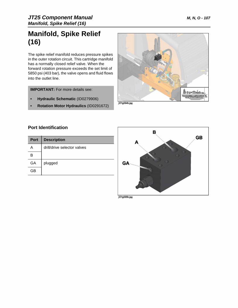
JT25 Component Manual M, N, O - 107Manifold, Spike Relief (16)
Manifold, Spike Relief (16) The spike relief manifold reduces pressure spikes in the outer rotation circuit. This cartridge manifold has a normally closed relief valve. When the forward rotation pressure exceeds the set limit of 5850 psi (403 bar), the valve opens and fluid flows into the outlet line.
Port Identification
IMPORTANT: For more details see:
• Hydraulic Schematic (ID0279906)
• Rotation Motor Hydraulics (ID0291672)
Port Description
A drill/drive selector valves
B
GA plugged
GB
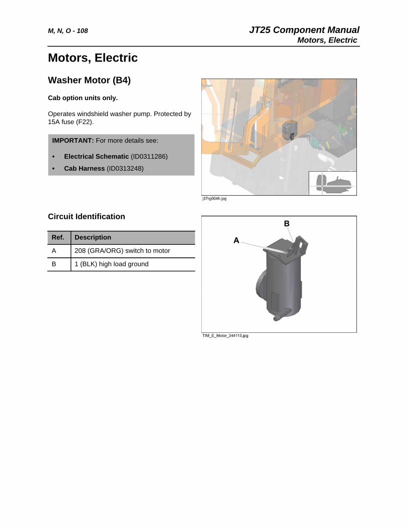
M, N, O - 108 JT25 Component ManualMotors, Electric
Motors, Electric
Washer Motor (B4)
Cab option units only.
Operates windshield washer pump. Protected by 15A fuse (F22).
Circuit Identification
IMPORTANT: For more details see:
• Electrical Schematic (ID0311286)
• Cab Harness (ID0313248)
Ref. Description
A 208 (GRA/ORG) switch to motor
B 1 (BLK) high load ground
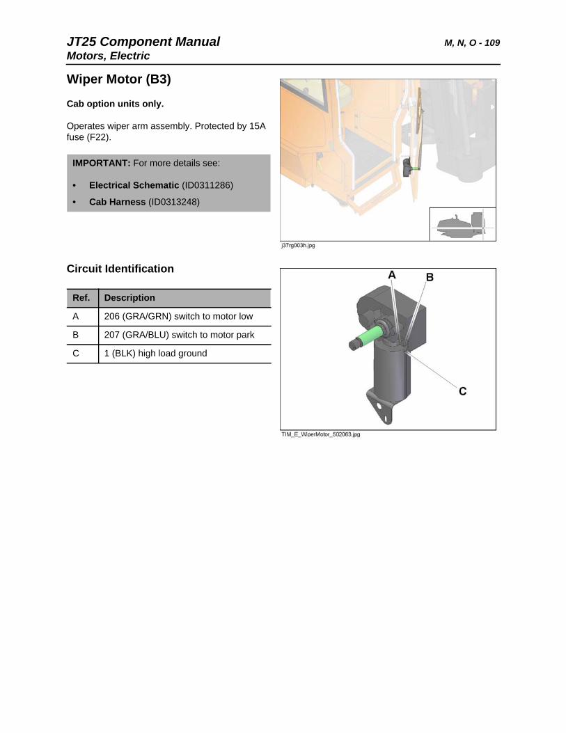
JT25 Component Manual M, N, O - 109Motors, Electric
Wiper Motor (B3)
Cab option units only.
Operates wiper arm assembly. Protected by 15A fuse (F22).
Circuit Identification
IMPORTANT: For more details see:
• Electrical Schematic (ID0311286)
• Cab Harness (ID0313248)
Ref. Description
A 206 (GRA/GRN) switch to motor low
B 207 (GRA/BLU) switch to motor park
C 1 (BLK) high load ground
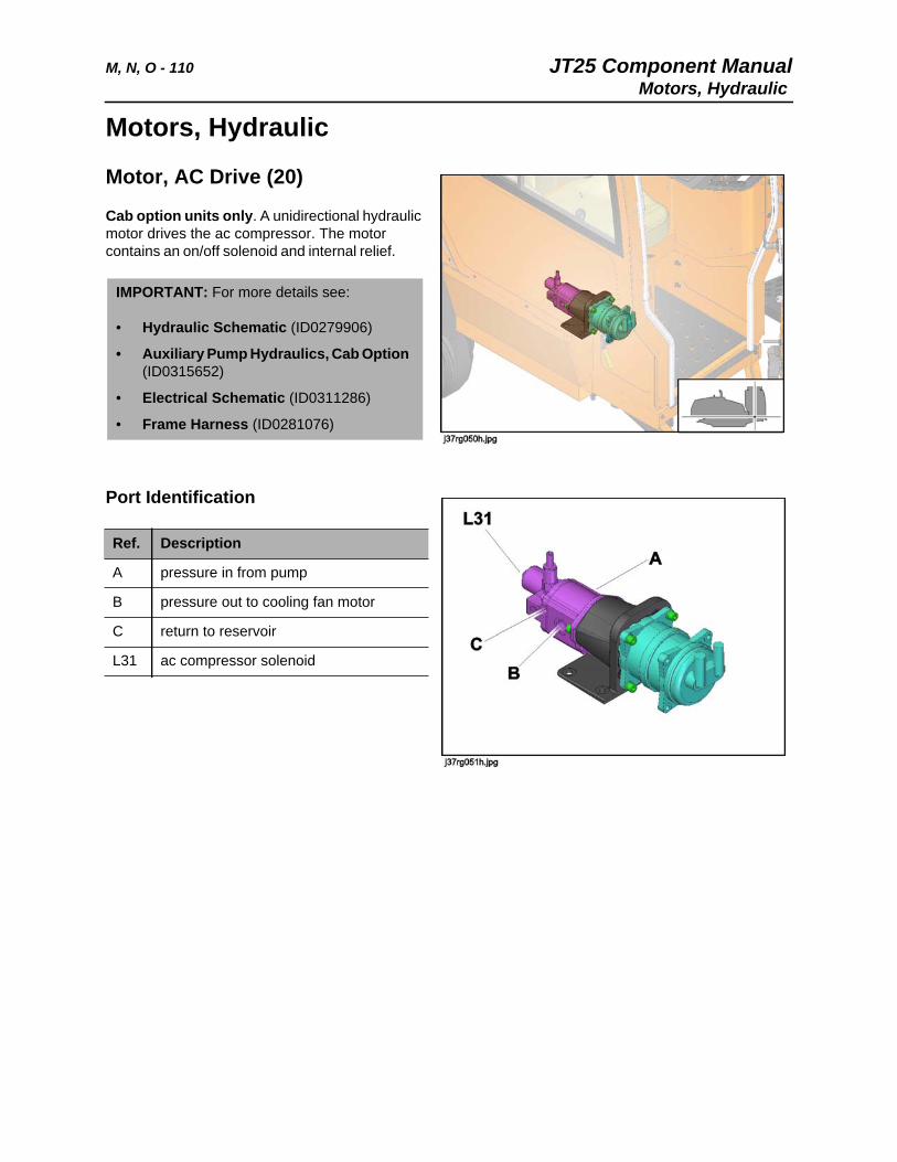
M, N, O - 110 JT25 Component ManualMotors, Hydraulic
Motors, Hydraulic
Motor, AC Drive (20)
Cab option units only. A unidirectional hydraulic motor drives the ac compressor. The motor contains an on/off solenoid and internal relief.
Port Identification
IMPORTANT: For more details see:
• Hydraulic Schematic (ID0279906)
• Auxiliary Pump Hydraulics, Cab Option (ID0315652)
• Electrical Schematic (ID0311286)
• Frame Harness (ID0281076)
Ref. Description
A pressure in from pump
B pressure out to cooling fan motor
C return to reservoir
L31 ac compressor solenoid
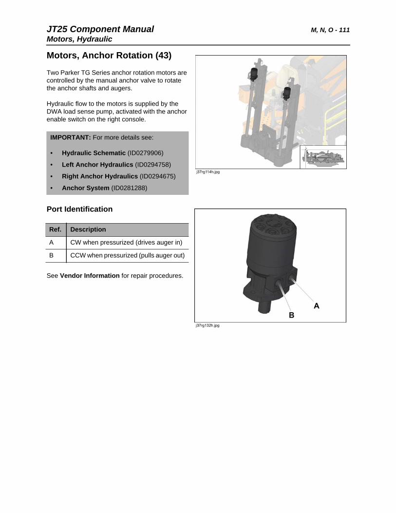
JT25 Component Manual M, N, O - 111Motors, Hydraulic
Motors, Anchor Rotation (43)
Two Parker TG Series anchor rotation motors are controlled by the manual anchor valve to rotate the anchor shafts and augers.
Hydraulic flow to the motors is supplied by the DWA load sense pump, activated with the anchor enable switch on the right console.
Port Identification
See Vendor Information for repair procedures.
IMPORTANT: For more details see:
• Hydraulic Schematic (ID0279906)
• Left Anchor Hydraulics (ID0294758)
• Right Anchor Hydraulics (ID0294675)
• Anchor System (ID0281288)
Ref. Description
A CW when pressurized (drives auger in)
B CCW when pressurized (pulls auger out)
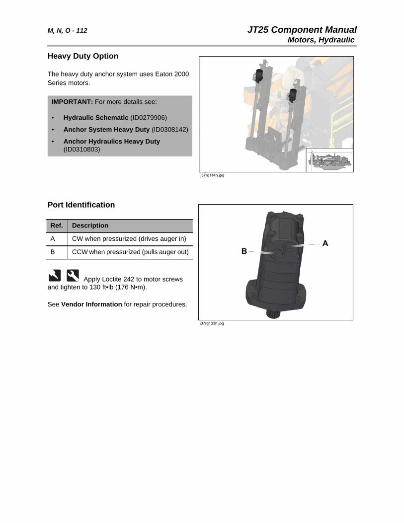
M, N, O - 112 JT25 Component ManualMotors, Hydraulic
Heavy Duty Option
The heavy duty anchor system uses Eaton 2000 Series motors.
Port Identification
Apply Loctite 242 to motor screws and tighten to 130 ft•lb (176 N•m).
See Vendor Information for repair procedures.
IMPORTANT: For more details see:
• Hydraulic Schematic (ID0279906)
• Anchor System Heavy Duty (ID0308142)
• Anchor Hydraulics Heavy Duty (ID0310803)
Ref. Description
A CW when pressurized (drives auger in)
B CCW when pressurized (pulls auger out)
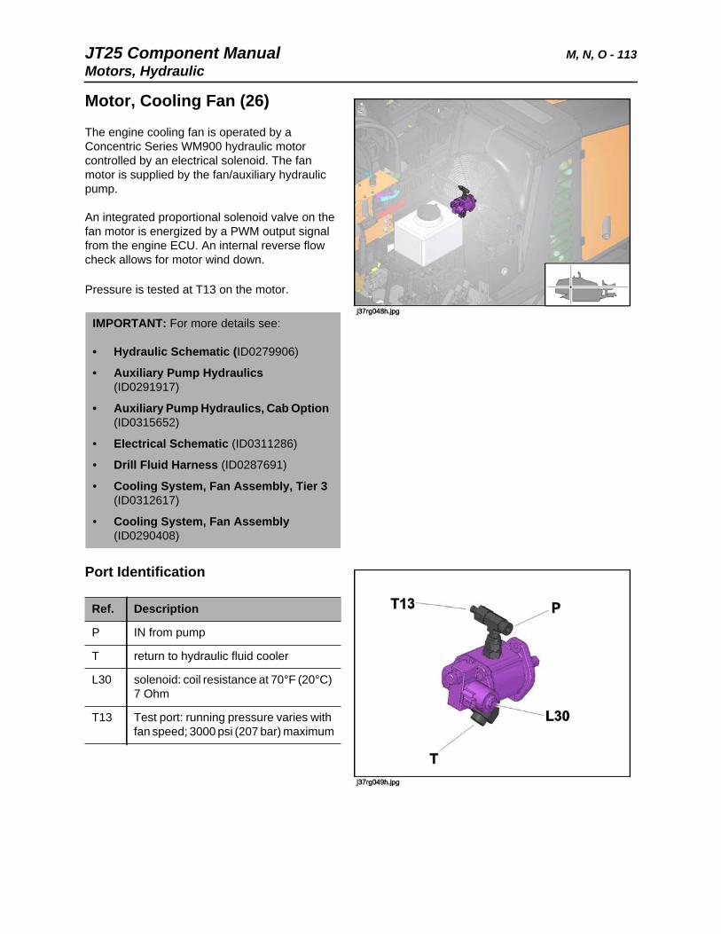
JT25 Component Manual M, N, O - 113Motors, Hydraulic
Motor, Cooling Fan (26)
The engine cooling fan is operated by a Concentric Series WM900 hydraulic motor controlled by an electrical solenoid. The fan motor is supplied by the fan/auxiliary hydraulic pump.
An integrated proportional solenoid valve on the fan motor is energized by a PWM output signal from the engine ECU. An internal reverse flow check allows for motor wind down.
Pressure is tested at T13 on the motor.
Port Identification
IMPORTANT: For more details see:
• Hydraulic Schematic (ID0279906)
• Auxiliary Pump Hydraulics (ID0291917)
• Auxiliary Pump Hydraulics, Cab Option (ID0315652)
• Electrical Schematic (ID0311286)
• Drill Fluid Harness (ID0287691)
• Cooling System, Fan Assembly, Tier 3 (ID0312617)
• Cooling System, Fan Assembly (ID0290408)
Ref. Description
P IN from pump
T return to hydraulic fluid cooler
L30 solenoid: coil resistance at 70°F (20°C) 7 Ohm
T13 Test port: running pressure varies with fan speed; 3000 psi (207 bar) maximum
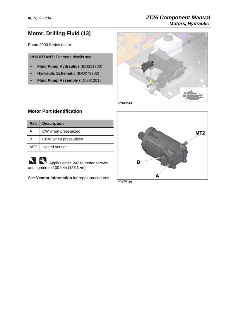
M, N, O - 114 JT25 Component ManualMotors, Hydraulic
Motor, Drilling Fluid (13)
Eaton 2000 Series motor.
Motor Port Identification
Apply Loctite 242 to motor screws and tighten to 100 ft•lb (136 N•m).
See Vendor Information for repair procedures.
IMPORTANT: For more details see:
• Fluid Pump Hydraulics (ID0311703)
• Hydraulic Schematic (IDO279906)
• Fluid Pump Assembly (ID0291201)
Ref. Description
A CW when pressurized
B CCW when pressurized
MT2 speed sensor
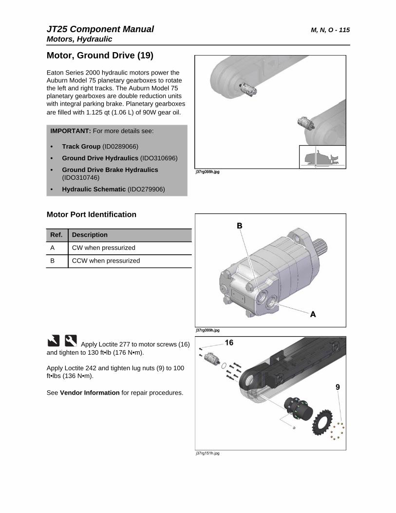
JT25 Component Manual M, N, O - 115Motors, Hydraulic
Motor, Ground Drive (19)
Eaton Series 2000 hydraulic motors power the Auburn Model 75 planetary gearboxes to rotate the left and right tracks. The Auburn Model 75 planetary gearboxes are double reduction units with integral parking brake. Planetary gearboxes are filled with 1.125 qt (1.06 L) of 90W gear oil.
Motor Port Identification
Apply Loctite 277 to motor screws (16) and tighten to 130 ft•lb (176 N•m).
Apply Loctite 242 and tighten lug nuts (9) to 100 ft•lbs (136 N•m).
See Vendor Information for repair procedures.
IMPORTANT: For more details see:
• Track Group (ID0289066)
• Ground Drive Hydraulics (IDO310696)
• Ground Drive Brake Hydraulics (IDO310746)
• Hydraulic Schematic (IDO279906)
Ref. Description
A CW when pressurized
B CCW when pressurized
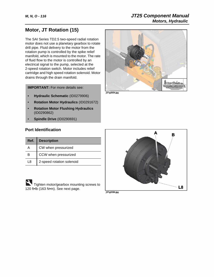
M, N, O - 116 JT25 Component ManualMotors, Hydraulic
Motor, JT Rotation (15)
The SAI Series TD2.5 two-speed radial rotation motor does not use a planetary gearbox to rotate drill pipe. Fluid delivery to the motor from the rotation pump is controlled by the spike relief manifold, which is mounted to the motor. The rate of fluid flow to the motor is controlled by an electrical signal to the pump, selected at the 2-speed rotation switch. Motor includes relief cartridge and high speed rotation solenoid. Motor drains through the drain manifold.
Port Identification
Tighten motor/gearbox mounting screws to 120 ft•lb (163 N•m). See next page.
IMPORTANT: For more details see:
• Hydraulic Schematic (ID0279906)
• Rotation Motor Hydraulics (ID0291672)
• Rotation Motor Flushing Hydraulics (ID0290862)
• Spindle Drive (ID0290691)
Ref. Description
A CW when pressurized
B CCW when pressurized
L8 2-speed rotation solenoid
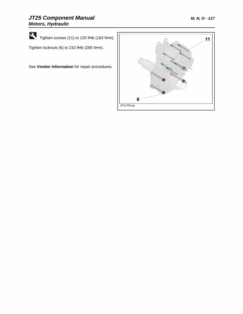
JT25 Component Manual M, N, O - 117Motors, Hydraulic
Tighten screws (11) to 120 ft•lb (163 N•m).
Tighten locknuts (6) to 210 ft•lb (285 N•m).
See Vendor Information for repair procedures.
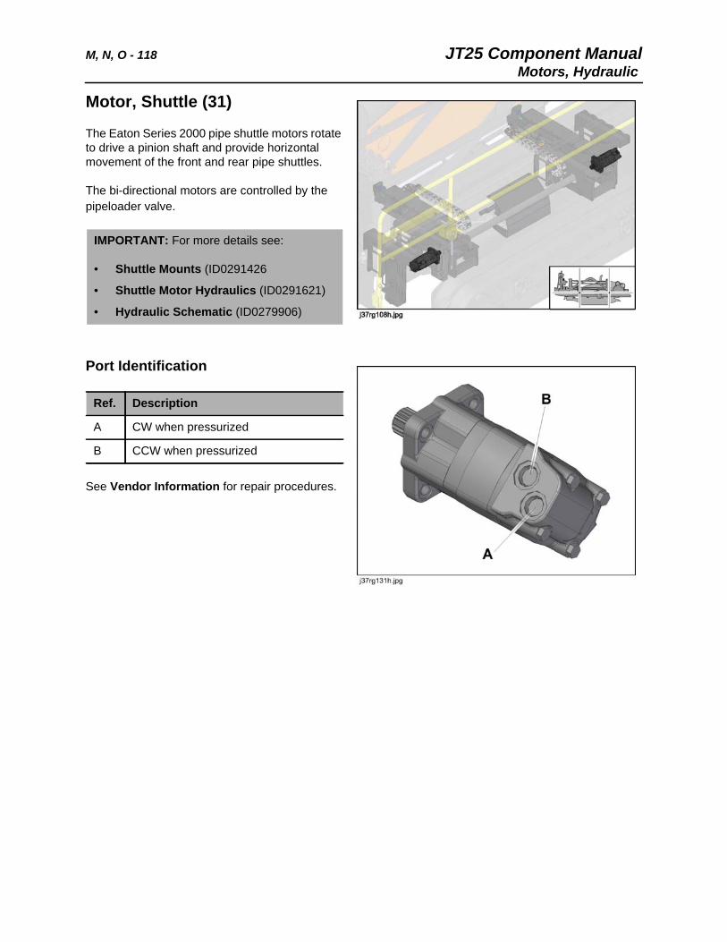
M, N, O - 118 JT25 Component ManualMotors, Hydraulic
Motor, Shuttle (31)
The Eaton Series 2000 pipe shuttle motors rotate to drive a pinion shaft and provide horizontal movement of the front and rear pipe shuttles.
The bi-directional motors are controlled by the pipeloader valve.
Port Identification
See Vendor Information for repair procedures.
IMPORTANT: For more details see:
• Shuttle Mounts (ID0291426
• Shuttle Motor Hydraulics (ID0291621)
• Hydraulic Schematic (ID0279906)
Ref. Description
A CW when pressurized
B CCW when pressurized
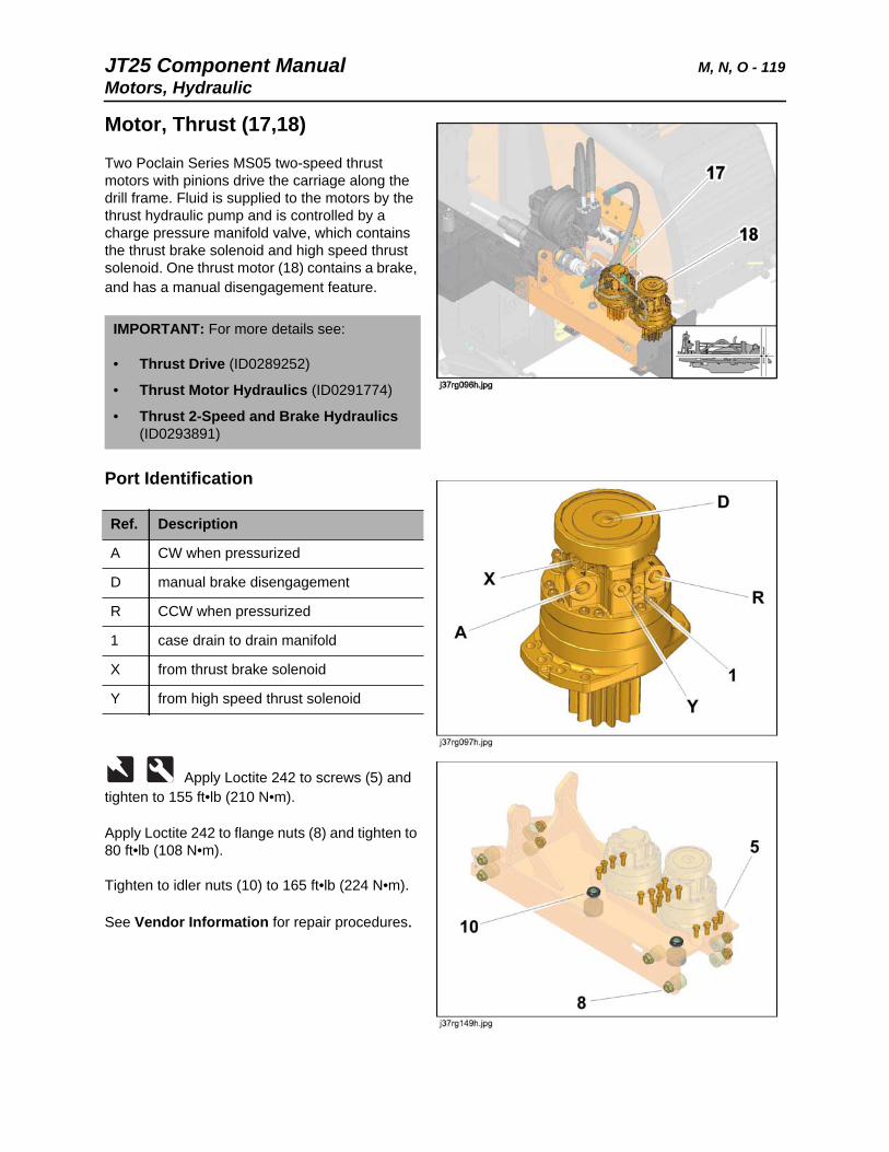
JT25 Component Manual M, N, O - 119Motors, Hydraulic
Motor, Thrust (17,18)
Two Poclain Series MS05 two-speed thrust motors with pinions drive the carriage along the drill frame. Fluid is supplied to the motors by the thrust hydraulic pump and is controlled by a charge pressure manifold valve, which contains the thrust brake solenoid and high speed thrust solenoid. One thrust motor (18) contains a brake, and has a manual disengagement feature.
Port Identification
Apply Loctite 242 to screws (5) and tighten to 155 ft•lb (210 N•m).
Apply Loctite 242 to flange nuts (8) and tighten to 80 ft•lb (108 N•m).
Tighten to idler nuts (10) to 165 ft•lb (224 N•m).
See Vendor Information for repair procedures.
IMPORTANT: For more details see:
• Thrust Drive (ID0289252)
• Thrust Motor Hydraulics (ID0291774)
• Thrust 2-Speed and Brake Hydraulics (ID0293891)
Ref. Description
A CW when pressurized
D manual brake disengagement
R CCW when pressurized
1 case drain to drain manifold
X from thrust brake solenoid
Y from high speed thrust solenoid

M, N, O - 120 JT25 Component ManualMotors, Hydraulic
JT25 Component Manual P, Q - 121
P, Q
Chapter Contents
Potentiometers . . . . . . . . . . . . . . . .See Left Console
Pump, Grease . . . . . . . . . . . . . . . . . . . . . . . . . . . . 122
Pump, Drilling Fluid . . . . . . . . . . . . . . . . . . . . . . . 124
Pumps, Hydraulic . . . . . . . . . . . . . . . . . . . . . . . . . 125
• Fan/Auxiliary Pump. . . . . . . . . . . . . . . . . . . . . . . . . . . . . . . . . . . . . . . 125
• Rotation/Left Track Pump . . . . . . . . . . . . . . . . . . . . . . . . . . . . . . . . . . 126
• Thrust/Right Track Pump . . . . . . . . . . . . . . . . . . . . . . . . . . . . . . . . . . 128
• DWA Load Sense Pump . . . . . . . . . . . . . . . . . . . . . . . . . . . . . . . . . . . 130
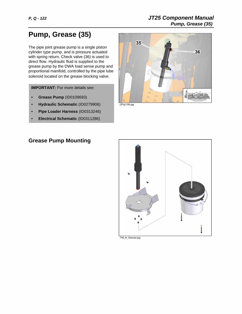
P, Q - 122 JT25 Component ManualPump, Grease (35)
Pump, Grease (35) The pipe joint grease pump is a single piston cylinder type pump, and is pressure actuated with spring return. Check valve (36) is used to direct flow. Hydraulic fluid is supplied to the grease pump by the DWA load sense pump and proportional manifold, controlled by the pipe lube solenoid located on the grease blocking valve.
Grease Pump Mounting
IMPORTANT: For more details see:
• Grease Pump (ID0109693)
• Hydraulic Schematic (ID0279906)
• Pipe Loader Harness (ID0313246)
• Electrical Schematic (ID0311286)
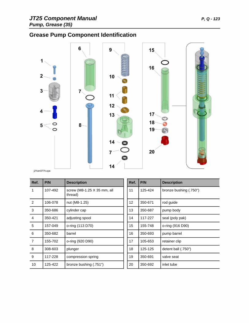
JT25 Component Manual P, Q - 123Pump, Grease (35)
Grease Pump Component Identification
Ref. P/N Description Ref. P/N Description
1 107-492 screw (M8-1.25 X 35 mm, all thread)
11 125-424 bronze bushing (.750")
2 106-078 nut (M8-1.25) 12 350-671 rod guide
3 350-686 cylinder cap 13 350-687 pump body
4 350-421 adjusting spool 14 117-227 seal (poly pak)
5 157-049 o-ring (113 D70) 15 155-748 o-ring (916 D90)
6 350-682 barrel 16 350-693 pump barrel
7 155-702 o-ring (920 D90) 17 105-653 retainer clip
8 308-603 plunger 18 125-125 detent ball (.750")
9 117-228 compression spring 19 350-691 valve seat
10 125-422 bronze bushing (.751") 20 350-692 inlet tube
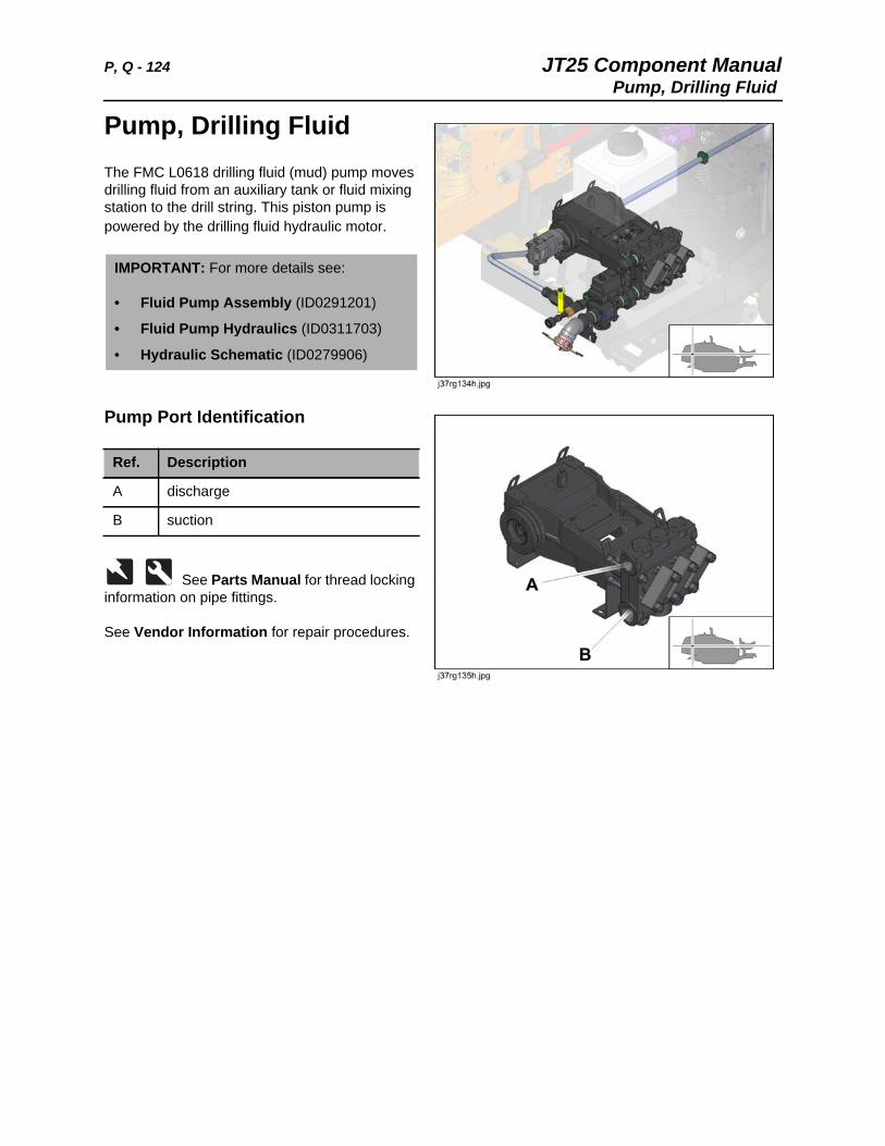
P, Q - 124 JT25 Component ManualPump, Drilling Fluid
Pump, Drilling Fluid The FMC L0618 drilling fluid (mud) pump moves drilling fluid from an auxiliary tank or fluid mixing station to the drill string. This piston pump is powered by the drilling fluid hydraulic motor.
Pump Port Identification
See Parts Manual for thread locking information on pipe fittings.
See Vendor Information for repair procedures.
IMPORTANT: For more details see:
• Fluid Pump Assembly (ID0291201)
• Fluid Pump Hydraulics (ID0311703)
• Hydraulic Schematic (ID0279906)
Ref. Description
A discharge
B suction
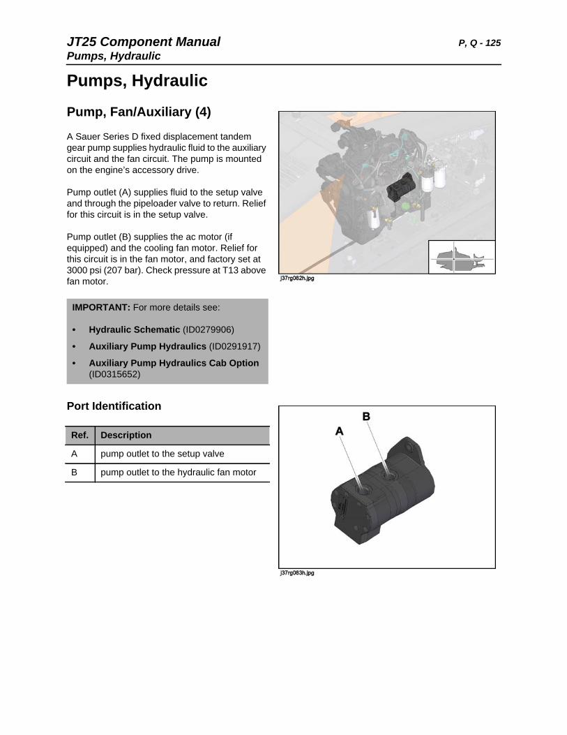
JT25 Component Manual P, Q - 125Pumps, Hydraulic
Pumps, Hydraulic
Pump, Fan/Auxiliary (4)
A Sauer Series D fixed displacement tandem gear pump supplies hydraulic fluid to the auxiliary circuit and the fan circuit. The pump is mounted on the engine’s accessory drive.
Pump outlet (A) supplies fluid to the setup valve and through the pipeloader valve to return. Relief for this circuit is in the setup valve.
Pump outlet (B) supplies the ac motor (if equipped) and the cooling fan motor. Relief for this circuit is in the fan motor, and factory set at 3000 psi (207 bar). Check pressure at T13 above fan motor.
Port Identification
IMPORTANT: For more details see:
• Hydraulic Schematic (ID0279906)
• Auxiliary Pump Hydraulics (ID0291917)
• Auxiliary Pump Hydraulics Cab Option (ID0315652)
Ref. Description
A pump outlet to the setup valve
B pump outlet to the hydraulic fan motor

P, Q - 126 JT25 Component ManualPumps, Hydraulic
Rotation/Left Track Pump (1)
This hydrostat Sauer-Danfoss Series H1 variable hydrostat pump uses 12V electrical displacement controls with manual overrides. Rotation/left track pump (1) includes a charge pump and test ports for charge and case pressure, and case pressure bypass check valve.
Charge relief is set at 430 psi (30 bar), tested at T1, and adjusted at R1.
CC and CCW high pressure main relief valves are preset at 6000 psi (414 bar) and are not adjustable. Test at T4 and T3, respectively.
Case pressure is 40 psi (2.8 bar) maximum, tested at T2. Pump case flow check is located at reservoir fitting.
EDC coil resistance at 70°F (21°C) is 3.66 Ohm.
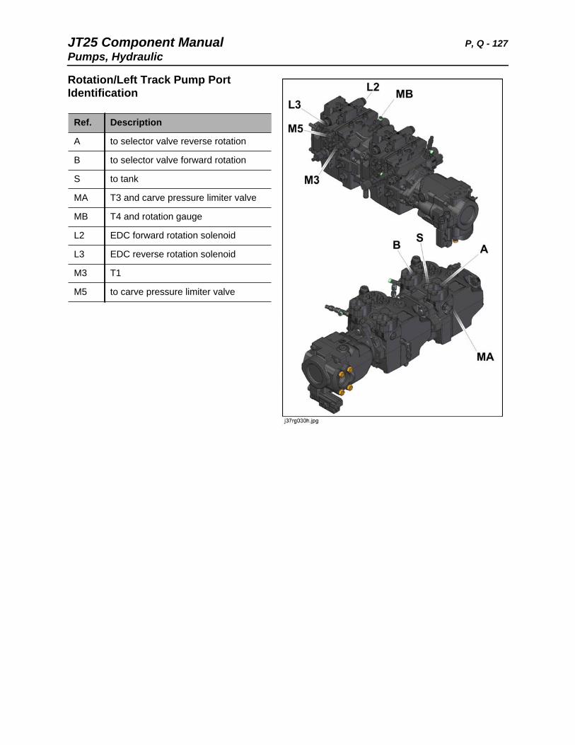
JT25 Component Manual P, Q - 127Pumps, Hydraulic
Rotation/Left Track Pump Port Identification
Ref. Description
A to selector valve reverse rotation
B to selector valve forward rotation
S to tank
MA T3 and carve pressure limiter valve
MB T4 and rotation gauge
L2 EDC forward rotation solenoid
L3 EDC reverse rotation solenoid
M3 T1
M5 to carve pressure limiter valve
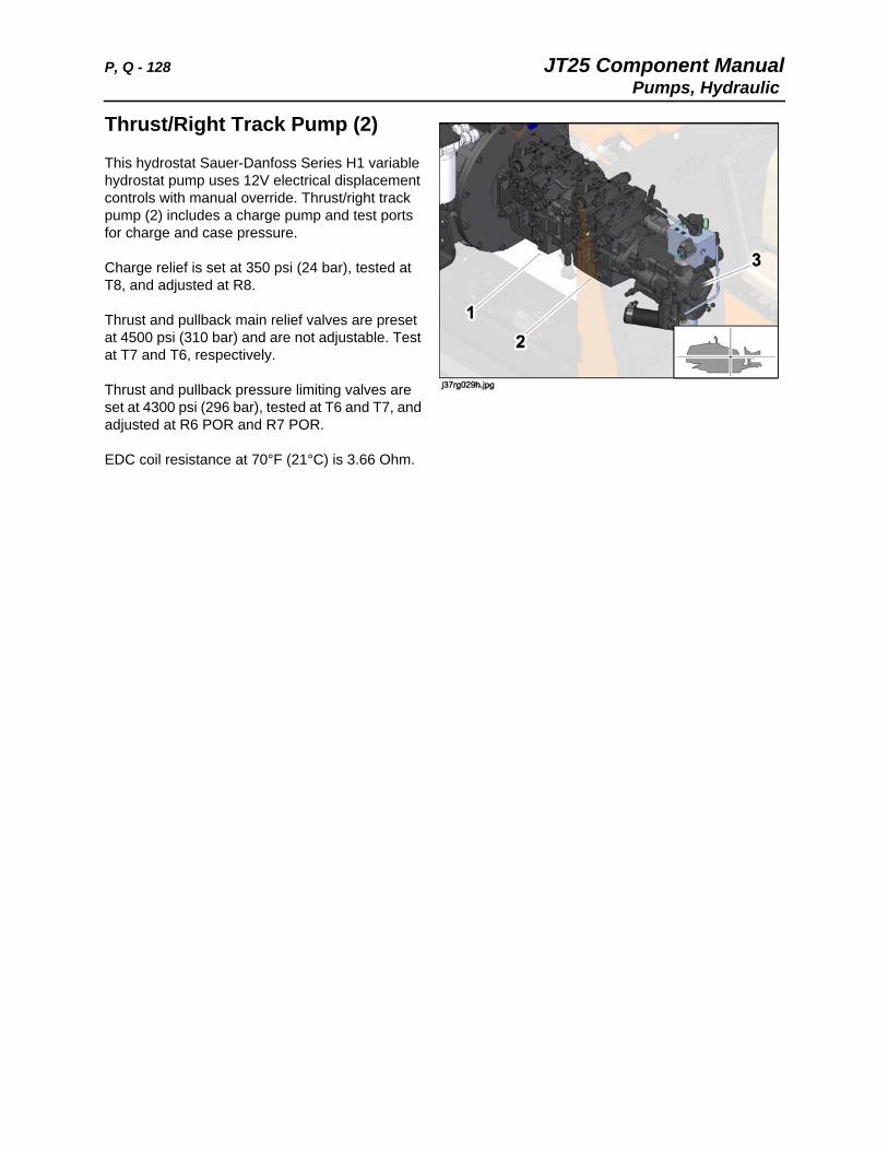
P, Q - 128 JT25 Component ManualPumps, Hydraulic
Thrust/Right Track Pump (2)
This hydrostat Sauer-Danfoss Series H1 variable hydrostat pump uses 12V electrical displacement controls with manual override. Thrust/right track pump (2) includes a charge pump and test ports for charge and case pressure.
Charge relief is set at 350 psi (24 bar), tested at T8, and adjusted at R8.
Thrust and pullback main relief valves are preset at 4500 psi (310 bar) and are not adjustable. Test at T7 and T6, respectively.
Thrust and pullback pressure limiting valves are set at 4300 psi (296 bar), tested at T6 and T7, and adjusted at R6 POR and R7 POR.
EDC coil resistance at 70°F (21°C) is 3.66 Ohm.
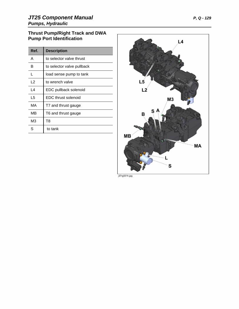
JT25 Component Manual P, Q - 129Pumps, Hydraulic
Thrust Pump/Right Track and DWA Pump Port Identification
Ref. Description
A to selector valve thrust
B to selector valve pullback
L load sense pump to tank
L2 to wrench valve
L4 EDC pullback solenoid
L5 EDC thrust solenoid
MA T7 and thrust gauge
MB T6 and thrust gauge
M3 T8
S to tank
P, Q - 130 JT25 Component ManualPumps, Hydraulic
DWA Load Sense Pump (3)
The Sauer-Danfoss Series 45 DWA pressure compensated load sense pump (3) supplies the proportional manifold, grease pump blocking valve, anchor valve, wrench valve, and drilling fluid manifold.
A proportional valve controls pump output by variable swash plate position. Uses 12V start-blocking solenoid valve and 12V load sense proportional flow control valve.
See “DWA Load Sense Pump Diode, Inline (D15)” on page 71.
Apply Loctite 242 to DWA load sense pump mounting screws and tighten to 25 ft•lb (34
N•m).
See Vendor Information for repair procedures.
IMPORTANT: For more details see:
• Hydraulic Schematic (ID0279906)
• Pump Mount (ID0291353)
• Rotation Pump Hydraulics (ID0291848)
• Thrust Pump Hydraulics (ID0291841)
• Load Sense Pump Hydraulics (ID0291786)
• POR Flushing and Charge Hydraulics (ID0291815)
JT25 Component Manual R - 131Pumps, Hydraulic
R
Chapter Contents
Radiator/Cooler . . . . . . . . . . . . . . . . . . . . . . . . . . . 132
Relays, Electrical . . . . . . . . . . . . . . . . . . . . . . . . . 133
• Main Relays . . . . . . . . . . . . . . . . . . . See Fuse, Diode and Relay Panels
• Cab Relay . . . . . . . . . . . . . . . . . . . . . . . . . . . . . . . . . . . . . . . . . . . . . . 133
• FMS Relay . . . . . . . . . . . . . . . . . . . . . . . . . . . . . . . . . . . . . . . . . . . . . 134
• Intake Air Heater Relay . . . . . . . . . . . . . . . . . . . . . . . . . . . . . . . . . . . . 135
• Rear Hood Contactor Relay . . . . . . . . . . . . . . . . . . . . . . . . . . . . . . . . 136
Resistors, Electrical . . . . . . . . . . . . . . . . . . . . . . . 137
• CAN Terminating Resistor . . . . . . . . . . . . . . . . . . . . . . . . . . . . . See CAN
• Carve Angle Potentiometer . . . . . . . . . . . . . . . . . . . . . . .See Left Console
• Coolant Level Sensor . . . . . . . . . . . . . . . . . . . . . . . . . . . . . . See Sensors
• Drilling Fluid Speed Sensor Resistor Pack . . . . . . . . . . . . . . . . . . . . . 137
• Fluid Flow Potentiometer . . . . . . . . . . . . . . . . . . . . . . . .See Left Console
• Fuel Sender. . . . . . . . . . . . . . . . . . . . . . . . . . . . . . . . . . . . See Tank, Fuel
• Resistor Module . . . . . . . . . . . . . . . . . . . . . . . . . . . . . . . . . . . . . . . . . 138
• Rotation Speed Sensor Resistor Pack . . . . . . . . . . . . . . . . . . . . . . . . 139
• Track Override Resistor Pack . . . . . . . . . . . . . . . . . . . . . . . . . . . . . . . 140
• Tracker/LED Resistor Pack. . . . . . . . . . . . . . . . . . . . . . . . . . . . . . . . . 141
Reservoir, Hydraulic . . . . . . . . . . . . . . . . . . . . . . . 142
R - 132 JT25 Component ManualRadiator/Cooler (28)
Radiator/Cooler (28) A three-section heat exchanger/radiator cools hydraulic fluid, engine coolant, and engine intake charge air. The top portion of the radiator cools intake air, the middle portion cools engine coolant, and the lower portion cools hydraulic fluid.
A pressurized expansion tank with sight glass is added to the coolant section and also connects directly to the engine. The tank uses a 16 psi (1 bar) pressure cap, and includes a coolant level sensor. See “Coolant Level Sensor (R2)” on page 147.
A bypass valve is plumbed into the hydraulic portion of the fluid cooler to assist in cold weather operation. See “Valve, Cooler Bypass (27)” on page 180.
Port Identification
IMPORTANT: For more details see:
• Hydraulic Oil Cooler (ID0291783)
• Cooling System Plumbing Tier 3 (ID0312672)
• Cooling System Plumbing Tier 4i (ID0290511)
Ref. Description
A charge air
B coolant
C rotation pump
D drilling fluid manifold/port F
E filter
F drilling fluid manifold/port D
G coolant
H charge air
T10 Test Port: cooler out/filter in 20 psi (1.4 bar) maximum
27 cooler bypass valve
JT25 Component Manual R - 133Relays, Electrical
Relays, Electrical
Relay, Cab (K16)
Cab option only. The cab relay is located on the right side frame, and latches to power the cab option circuits.
Component Identification
IMPORTANT: For more details see:
• Electrical Schematic (ID0311286)
• Frame Harness (ID0313263)
• Frame Harness (ID0281076)
Ref. Description
A 2 (RED) battery disconnect switch and cab fuse (F20)
B 2 (RED) to other cab options
C 9 (ORG/WHT) ignition switch
D 1A (BLK/RED) medium load ground
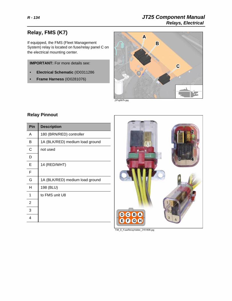
R - 134 JT25 Component ManualRelays, Electrical
Relay, FMS (K7)
If equipped, the FMS (Fleet Management System) relay is located on fuse/relay panel C on the electrical mounting center.
Relay Pinnout
IMPORTANT: For more details see:
• Electrical Schematic (ID0311286
• Frame Harness (ID0281076)
Pin Description
A 180 (BRN/RED) controller
B 1A (BLK/RED) medium load ground
C not used
D
E 14 (RED/WHT)
F
G 1A (BLK/RED) medium load ground
H 198 (BLU)
1 to FMS unit U8
2
3
4
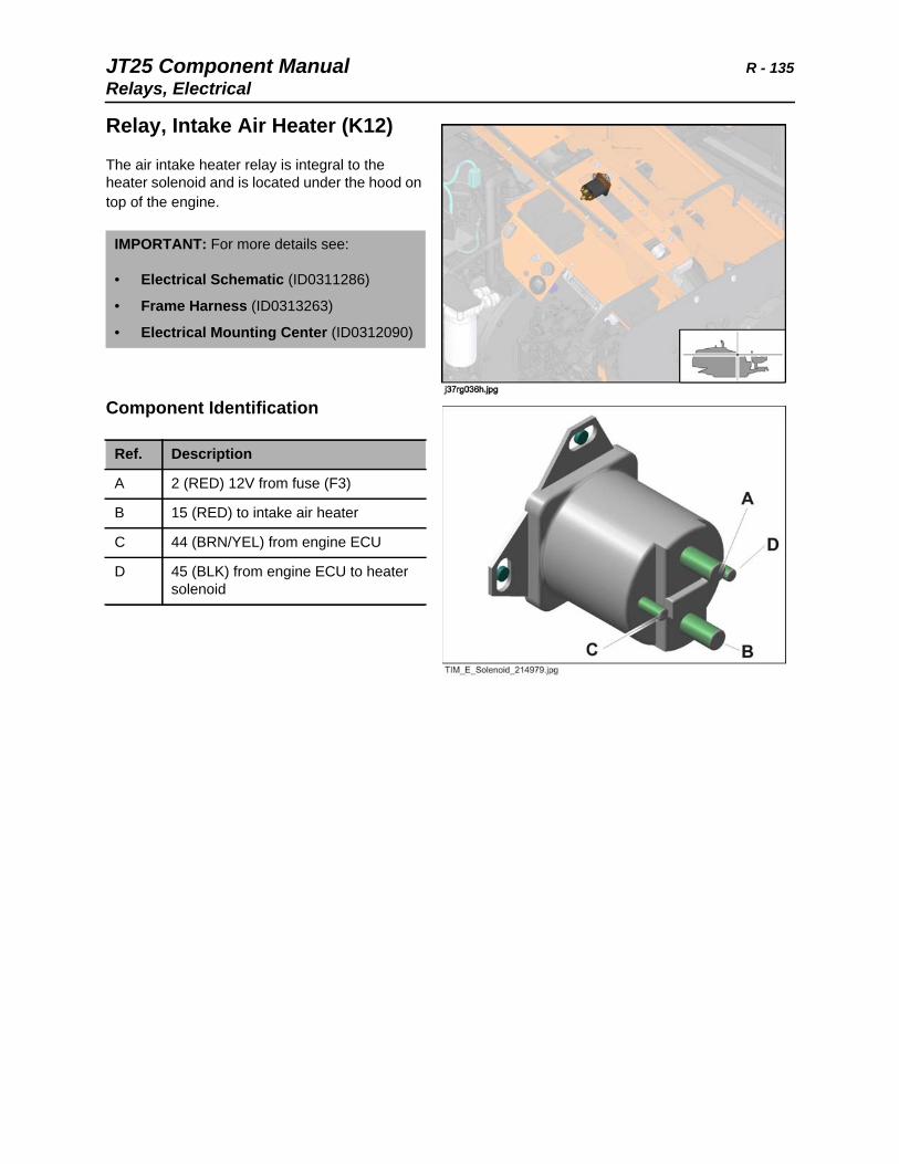
JT25 Component Manual R - 135Relays, Electrical
Relay, Intake Air Heater (K12)
The air intake heater relay is integral to the heater solenoid and is located under the hood on top of the engine.
Component Identification
IMPORTANT: For more details see:
• Electrical Schematic (ID0311286)
• Frame Harness (ID0313263)
• Electrical Mounting Center (ID0312090)
Ref. Description
A 2 (RED) 12V from fuse (F3)
B 15 (RED) to intake air heater
C 44 (BRN/YEL) from engine ECU
D 45 (BLK) from engine ECU to heater solenoid
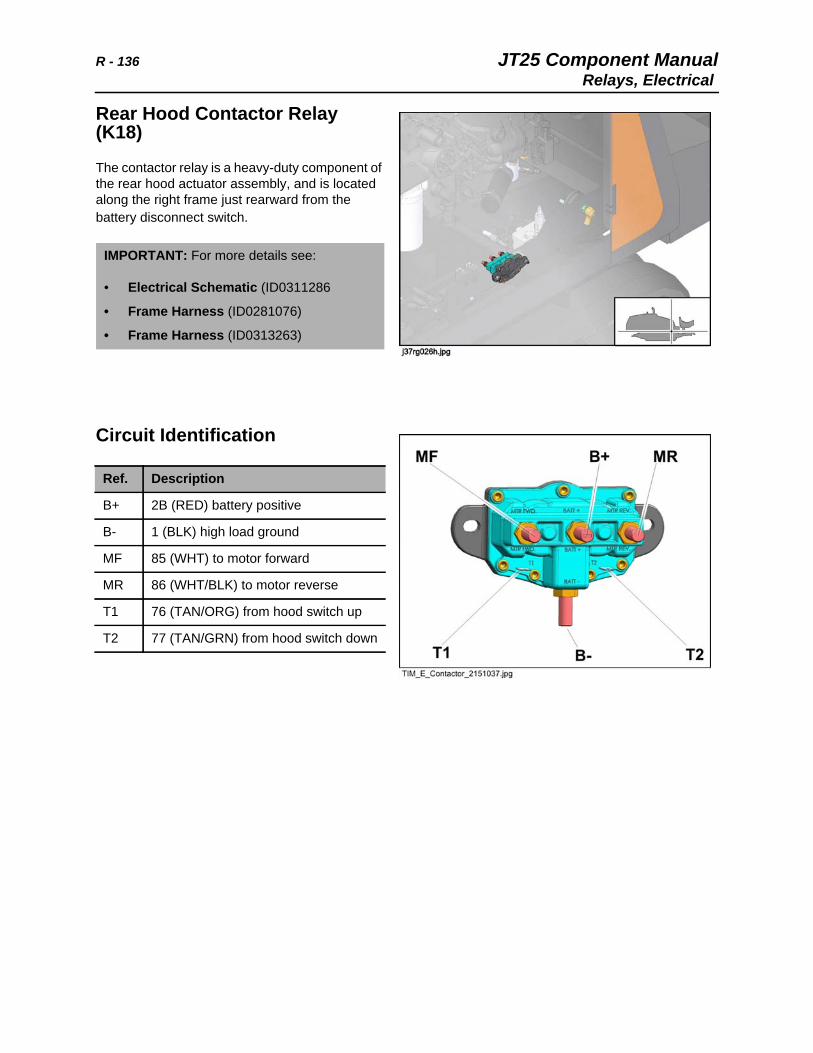
R - 136 JT25 Component ManualRelays, Electrical
Rear Hood Contactor Relay (K18)
The contactor relay is a heavy-duty component of the rear hood actuator assembly, and is located along the right frame just rearward from the battery disconnect switch.
Circuit Identification
IMPORTANT: For more details see:
• Electrical Schematic (ID0311286
• Frame Harness (ID0281076)
• Frame Harness (ID0313263)
Ref. Description
B+ 2B (RED) battery positive
B- 1 (BLK) high load ground
MF 85 (WHT) to motor forward
MR 86 (WHT/BLK) to motor reverse
T1 76 (TAN/ORG) from hood switch up
T2 77 (TAN/GRN) from hood switch down
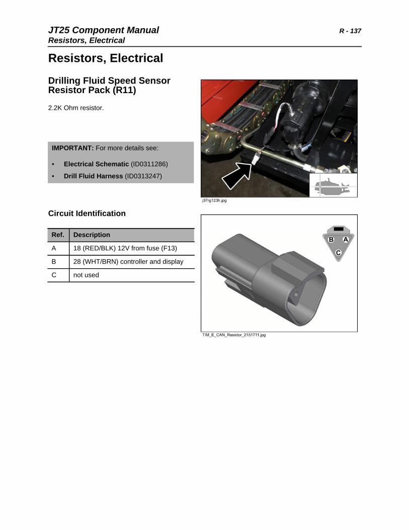
JT25 Component Manual R - 137Resistors, Electrical
Resistors, Electrical
Drilling Fluid Speed Sensor Resistor Pack (R11)
2.2K Ohm resistor.
Circuit Identification
IMPORTANT: For more details see:
• Electrical Schematic (ID0311286)
• Drill Fluid Harness (ID0313247)
Ref. Description
A 18 (RED/BLK) 12V from fuse (F13)
B 28 (WHT/BRN) controller and display
C not used
R - 138 JT25 Component ManualResistors, Electrical
Resistor, Module (U3)
The resister divider module is located inside the left console. It provides divided voltage (2.5V) to the pipe gripper switch CLOSE function.
Circuit Identification
Note: The alternate control configuration places this module on the right console.
IMPORTANT: For more details see:
• Electrical Schematic (ID0311286)
• Console (ID0315959)
• Operator Station Left Harness (ID0281679)
Ref. Description
A 116 (BLU/GRN) 5V in from controller
B 37 (GRN/BLU) 2.5V output
C not used
D 89 (YEL/BLK) ground from controller
JT25 Component Manual R - 139Resistors, Electrical
Rotation Speed Sensor Resistor Pack (R9, R10)
2.2K Ohm resistors.
Circuit Identification
IMPORTANT: For more details see:
• Electrical Schematic (ID0311286)
• Carriage Harness (ID0281789)
Ref. Description
A 18 (RED/BLK) 12V from fuse (F13)
B 115 (WHT/BLU) controller
C 114 (WHT/YEL) controller
R - 140 JT25 Component ManualResistors, Electrical
Track Override Resistor Pack (R12, R13) and Diode (D16)
150 Ohm resistors.
Circuit Identification
IMPORTANT: For more details see:
• Electrical Schematic (ID0311286)
• Rear Frame Harness (ID0313244)
Ref. Description
1 148 (GRA/WHT) track override switches and track override enable relay
2
3 not used
4
5 167 (BLU/WHT) left track override switch
6 168 (GRN/WHT) right track override switch
JT25 Component Manual R - 141Resistors, Electrical
Tracker/LED Resistor Pack (R5, R7)
This resistor pack contains R5 for the tracker remote display, and R7 for LED indicators DS4 and DS5.
Circuit Identification
IMPORTANT: For more details see:
• Electrical Schematic (ID0311286)
• Operator Station Right Harness (ID0281876)
Ref. Description
1 not used
2 103 (TAN/RED) tracker display
3 113 (TAN/BLK) controller
4 13 (ORG/GRN) 12V from fuse (F16)
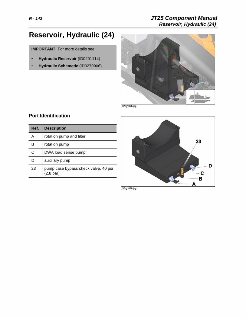
R - 142 JT25 Component ManualReservoir, Hydraulic (24)
Reservoir, Hydraulic (24)
Port Identification
IMPORTANT: For more details see:
• Hydraulic Reservoir (ID0291114)
• Hydraulic Schematic (ID0279906)
Ref. Description
A rotation pump and filter
B rotation pump
C DWA load sense pump
D auxiliary pump
23 pump case bypass check valve, 40 psi (2.8 bar)
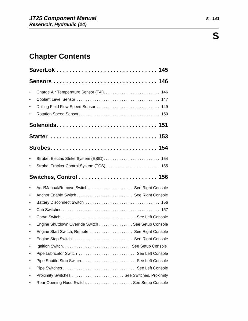
JT25 Component Manual S - 143Reservoir, Hydraulic (24)
S
Chapter Contents
SaverLok . . . . . . . . . . . . . . . . . . . . . . . . . . . . . . . . 145
Sensors . . . . . . . . . . . . . . . . . . . . . . . . . . . . . . . . . 146
• Charge Air Temperature Sensor (T4i). . . . . . . . . . . . . . . . . . . . . . . . . 146
• Coolant Level Sensor . . . . . . . . . . . . . . . . . . . . . . . . . . . . . . . . . . . . . 147
• Drilling Fluid Flow Speed Sensor . . . . . . . . . . . . . . . . . . . . . . . . . . . . 149
• Rotation Speed Sensor . . . . . . . . . . . . . . . . . . . . . . . . . . . . . . . . . . . . 150
Solenoids. . . . . . . . . . . . . . . . . . . . . . . . . . . . . . . . 151
Starter . . . . . . . . . . . . . . . . . . . . . . . . . . . . . . . . . . 153
Strobes. . . . . . . . . . . . . . . . . . . . . . . . . . . . . . . . . . 154
• Strobe, Electric Strike System (ESID). . . . . . . . . . . . . . . . . . . . . . . . . 154
• Strobe, Tracker Control System (TCS) . . . . . . . . . . . . . . . . . . . . . . . . 155
Switches, Control . . . . . . . . . . . . . . . . . . . . . . . . . 156
• Add/Manual/Remove Switch . . . . . . . . . . . . . . . . . . . . See Right Console
• Anchor Enable Switch . . . . . . . . . . . . . . . . . . . . . . . . . See Right Console
• Battery Disconnect Switch . . . . . . . . . . . . . . . . . . . . . . . . . . . . . . . . . 156
• Cab Switches . . . . . . . . . . . . . . . . . . . . . . . . . . . . . . . . . . . . . . . . . . . 157
• Carve Switch . . . . . . . . . . . . . . . . . . . . . . . . . . . . . . . . . .See Left Console
• Engine Shutdown Override Switch . . . . . . . . . . . . . . . See Setup Console
• Engine Start Switch, Remote . . . . . . . . . . . . . . . . . . . See Right Console
• Engine Stop Switch . . . . . . . . . . . . . . . . . . . . . . . . . . . See Right Console
• Ignition Switch . . . . . . . . . . . . . . . . . . . . . . . . . . . . . . See Setup Console
• Pipe Lubricator Switch . . . . . . . . . . . . . . . . . . . . . . . . . .See Left Console
• Pipe Shuttle Stop Switch. . . . . . . . . . . . . . . . . . . . . . . . .See Left Console
• Pipe Switches . . . . . . . . . . . . . . . . . . . . . . . . . . . . . . . . .See Left Console
• Proximity Switches . . . . . . . . . . . . . . . . . . . . . . . See Switches, Proximity
• Rear Opening Hood Switch. . . . . . . . . . . . . . . . . . . . . See Setup Console
S - 144 JT25 Component ManualReservoir, Hydraulic (24)
• Seat Switch . . . . . . . . . . . . . . . . . . . . . . . . . . . . . . . . . . . . . . . . . . . . . 158
• Seat/Cab Rotation Switch . . . . . . . . . . . . . . . . . . . . . . See Right Console
• Set/Resume Switch. . . . . . . . . . . . . . . . . . . . . . . . . . . . .See Left Console
• Throttle Switch . . . . . . . . . . . . . . . . . . . . . . . . . . . . . . . . . . . . . . . . . . 159
• Throttle Switch, Console . . . . . . . . . . . . . . . . . . . . . . . . .See Left Console
• Track Override Switches . . . . . . . . . . . . . . . . . . . . . . . See Setup Console
• Tracker Control Key Switch. . . . . . . . . . . . . . . . . . . . . . . . . . . . . . . . . 160
• Two-Speed Rotation Switch . . . . . . . . . . . . . . . . . . . . . .See Left Console
• Worklight Switch . . . . . . . . . . . . . . . . . . . . . . . . . . . . . . . . . . . . . . . . . 161
• Wrench Switches . . . . . . . . . . . . . . . . . . . . . . . . . . . . . .See Left Console
Switches, Pressure . . . . . . . . . . . . . . . . . . . See Filter
• Hydraulic Filter Pressure Switch . . . . . . . . . . . . . . . . . . . . . . . . . See Filter
• Hydraulic High Temperature Switch . . . . . . . . . . . . . . . . . . . . . . See Filter
Switches, Proximity . . . . . . . . . . . . . . . . . . . . . . . 162
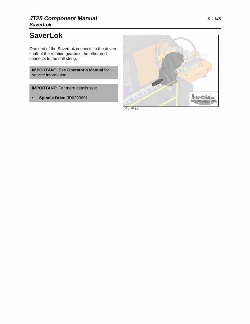
JT25 Component Manual S - 145SaverLok
SaverLokOne end of the SaverLok connects to the driven shaft of the rotation gearbox; the other end connects to the drill string.
IMPORTANT: See Operator’s Manual for service information.
IMPORTANT: For more details see:
• Spindle Drive (ID0290691
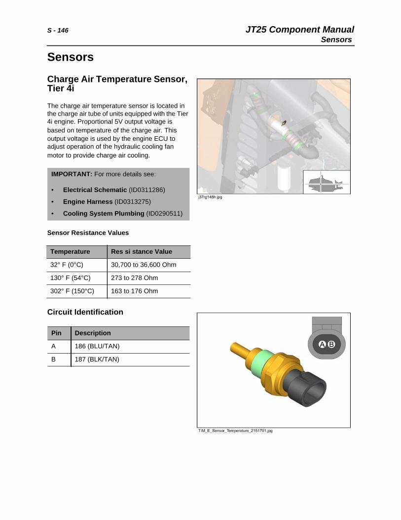
S - 146 JT25 Component ManualSensors
Sensors
Charge Air Temperature Sensor, Tier 4i
The charge air temperature sensor is located in the charge air tube of units equipped with the Tier 4i engine. Proportional 5V output voltage is based on temperature of the charge air. This output voltage is used by the engine ECU to adjust operation of the hydraulic cooling fan motor to provide charge air cooling.
Sensor Resistance Values
Circuit Identification
IMPORTANT: For more details see:
• Electrical Schematic (ID0311286)
• Engine Harness (ID0313275)
• Cooling System Plumbing (ID0290511)
Temperature Res si stance Value
32° F (0°C) 30,700 to 36,600 Ohm
130° F (54°C) 273 to 278 Ohm
302° F (150°C) 163 to 176 Ohm
Pin Description
A 186 (BLU/TAN)
B 187 (BLK/TAN)
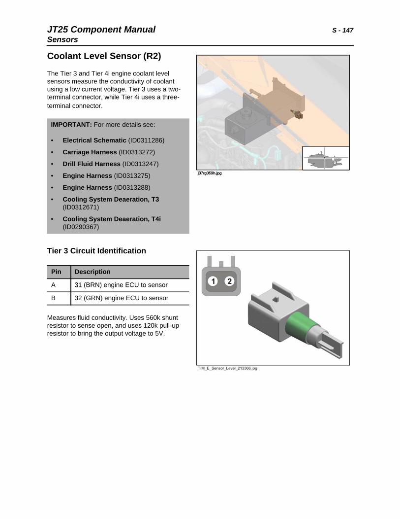
JT25 Component Manual S - 147Sensors
Coolant Level Sensor (R2)
The Tier 3 and Tier 4i engine coolant level sensors measure the conductivity of coolant using a low current voltage. Tier 3 uses a two-terminal connector, while Tier 4i uses a three-terminal connector.
Tier 3 Circuit Identification
Measures fluid conductivity. Uses 560k shunt resistor to sense open, and uses 120k pull-up resistor to bring the output voltage to 5V.
IMPORTANT: For more details see:
• Electrical Schematic (ID0311286)
• Carriage Harness (ID0313272)
• Drill Fluid Harness (ID0313247)
• Engine Harness (ID0313275)
• Engine Harness (ID0313288)
• Cooling System Deaeration, T3 (ID0312671)
• Cooling System Deaeration, T4i (ID0290367)
Pin Description
A 31 (BRN) engine ECU to sensor
B 32 (GRN) engine ECU to sensor
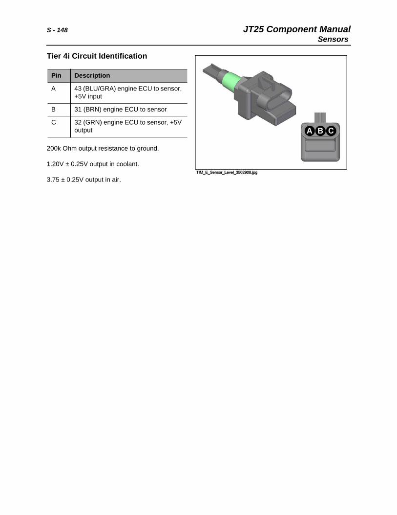
S - 148 JT25 Component ManualSensors
Tier 4i Circuit Identification
200k Ohm output resistance to ground.
1.20V ± 0.25V output in coolant.
3.75 ± 0.25V output in air.
Pin Description
A 43 (BLU/GRA) engine ECU to sensor, +5V input
B 31 (BRN) engine ECU to sensor
C 32 (GRN) engine ECU to sensor, +5V output
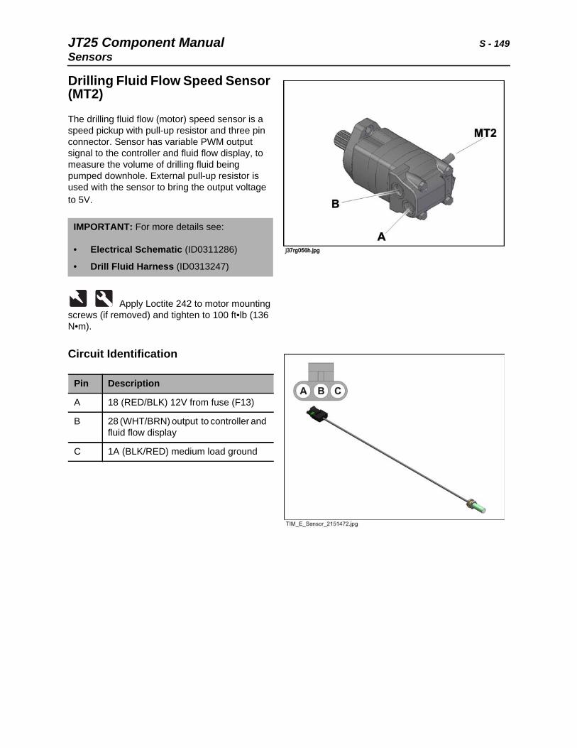
JT25 Component Manual S - 149Sensors
Drilling Fluid Flow Speed Sensor (MT2)
The drilling fluid flow (motor) speed sensor is a speed pickup with pull-up resistor and three pin connector. Sensor has variable PWM output signal to the controller and fluid flow display, to measure the volume of drilling fluid being pumped downhole. External pull-up resistor is used with the sensor to bring the output voltage to 5V.
Apply Loctite 242 to motor mounting screws (if removed) and tighten to 100 ft•lb (136 N•m).
Circuit Identification
IMPORTANT: For more details see:
• Electrical Schematic (ID0311286)
• Drill Fluid Harness (ID0313247)
Pin Description
A 18 (RED/BLK) 12V from fuse (F13)
B 28 (WHT/BRN) output to controller and fluid flow display
C 1A (BLK/RED) medium load ground
S - 150 JT25 Component ManualSensors
Rotation Speed Sensor (MT1)
A speed sensor on the JT rotation gearbox sends the rotation speed signal to the 60-pin V3 main controller. External pull-up resistors are used with the sensor to bring the voltage to 12V.
Circuit Identification
IMPORTANT: For more details see:
• Electrical Schematic (ID0311286)
• Carriage Harness (ID0313272)
• Gearbox (ID0286380)
Pin Description
A 18 (RED/BLK) 12V from fuse (F13)
B 1A (BLK/RED) medium load ground
C 115 (WHT/BLU) controller
D 114 (WHT/YEL) controller
JT25 Component Manual S - 151Solenoids
SolenoidsElectric solenoids actuate a variety of mechanical functions. Because solenoids are part of another component (such as a motor, pump, or valve), solenoid information is usually presented with the host component. See Service Reference Manual for general solenoid testing and service information.
Solenoid Reference
Ref. Solenoid Description Note
none starter solenoid Located on starter (B1) to control starter drive operation.
L1 load sense cutout solenoid Located on proportional manifold (42) at load sense pump. See page 106.
L2-L3 EDC solenoid Located on rotation pump (01) to control rotation/left track operation. See page 126.
L4-L5 EDC solenoid Located on thrust pump (02) to control thrust/right track operation. See page 126.
L6 track drive brake solenoid Located on charge pressure manifold (10) in engine compartment. See page 103.
L7 thrust brake solenoid Located on charge pressure manifold (09) on carriage. See page 102.
L8 2-speed rotation solenoid Located on JT rotation motor (15). See page 116.
L9 DWA pump solenoid/proportion valve Located on proportional manifold (42) at load sense pump. See page 106.
L10 drill/drive selector solenoid Located on charge pressure manifold (10) in engine compartment. See page 103.
L11 high speed thrust solenoid Located on charge pressure manifold (09) on carriage. See page 102.
L12 shuttle stop UP solenoid Located on pipe loading valve (08). Controls flow to hydraulic cylinders. See page 188.
L13 shuttle stop DOWN solenoid
L14 reverse rotation limiter solenoid Located on flushing/por manifold (49).
L15 front wrench clamp solenoid Located on wrench manifold (06). Controls flow to clamp cylinder.
L16 rear wrench clamp solenoid
L19 pipe lift UP solenoid Located on pipe loading valve (08). Controls flow to hydraulic cylinders.
L20 pipe lift DOWN solenoid
L21 pipe gripper OPEN solenoid
L22 pipe gripper CLOSE solenoid
S - 152 JT25 Component ManualSolenoids
L23 pipe end lubricator solenoid Located on grease blocking valve (50).
L24 pipe shuttle EXTEND solenoid Located on pipeloader valve (08). Controls flow to hydraulic cylinders.
L25 pipe shuttle RETRACT solenoid
L26 dump valve solenoid Located on pipeloader valve (08). Closing dump valve creates pressure in auxiliary valve to operate sections.
L27 cab swing OUT solenoid Located on pipeloader valve (08). Controls flow to hydraulic cylinder.
L28 cab swing IN solenoid
L29 drilling fluid solenoid Located on drilling fluid manifold (14).
L30 hydraulic fan motor solenoid Located on fan drive motor (26). Controls flow to hydraulic fan motor.
L31 compressor solenoid (cab option) Located on ac drive motor (20).
Ref. Solenoid Description Note
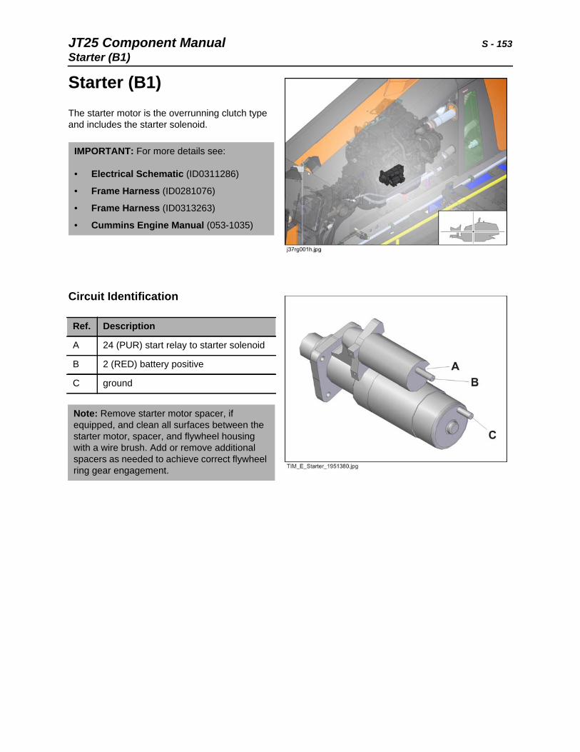
JT25 Component Manual S - 153Starter (B1)
Starter (B1)The starter motor is the overrunning clutch type and includes the starter solenoid.
Circuit Identification
IMPORTANT: For more details see:
• Electrical Schematic (ID0311286)
• Frame Harness (ID0281076)
• Frame Harness (ID0313263)
• Cummins Engine Manual (053-1035)
Ref. Description
A 24 (PUR) start relay to starter solenoid
B 2 (RED) battery positive
C ground
Note: Remove starter motor spacer, if equipped, and clean all surfaces between the starter motor, spacer, and flywheel housing with a wire brush. Add or remove additional spacers as needed to achieve correct flywheel ring gear engagement.
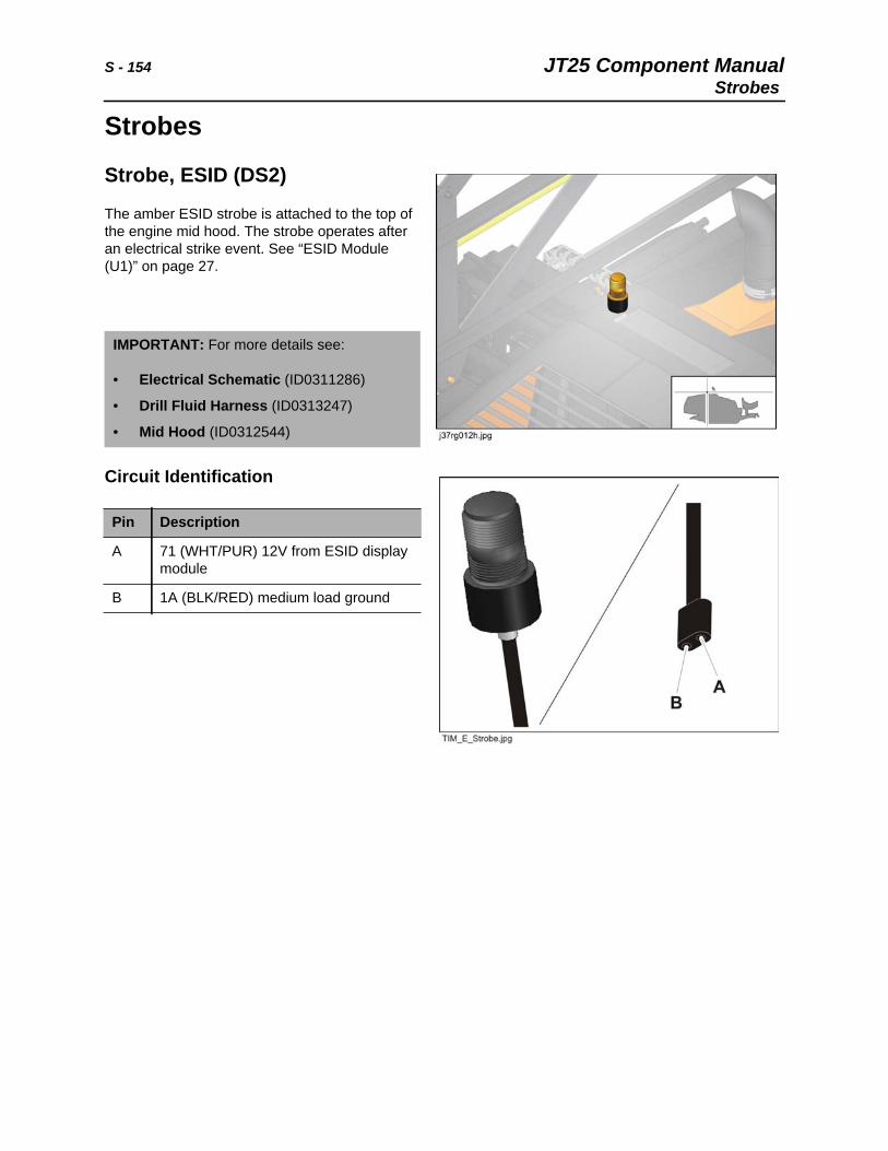
S - 154 JT25 Component ManualStrobes
Strobes
Strobe, ESID (DS2)
The amber ESID strobe is attached to the top of the engine mid hood. The strobe operates after an electrical strike event. See “ESID Module (U1)” on page 27.
Circuit Identification
IMPORTANT: For more details see:
• Electrical Schematic (ID0311286)
• Drill Fluid Harness (ID0313247)
• Mid Hood (ID0312544)
Pin Description
A 71 (WHT/PUR) 12V from ESID display module
B 1A (BLK/RED) medium load ground
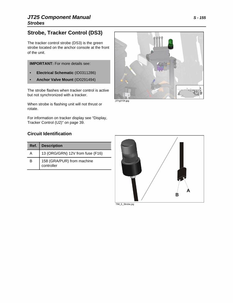
JT25 Component Manual S - 155Strobes
Strobe, Tracker Control (DS3)
The tracker control strobe (DS3) is the green strobe located on the anchor console at the front of the unit.
The strobe flashes when tracker control is active but not synchronized with a tracker.
When strobe is flashing unit will not thrust or rotate.
For information on tracker display see “Display, Tracker Control (U2)” on page 39.
Circuit Identification
IMPORTANT: For more details see:
• Electrical Schematic (ID0311286)
• Anchor Valve Mount (ID0291494)
Ref. Description
A 13 (ORG/GRN) 12V from fuse (F16)
B 158 (GRA/PUR) from machine controller
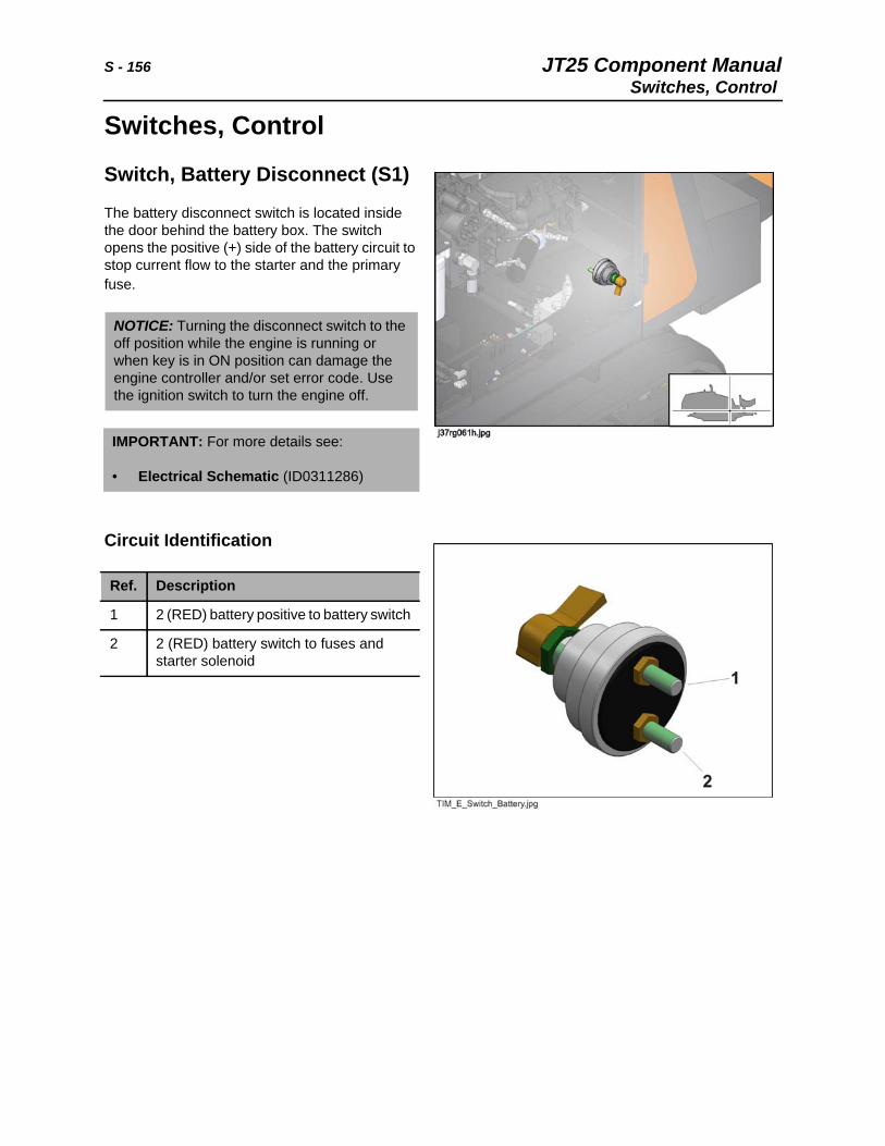
S - 156 JT25 Component ManualSwitches, Control
Switches, Control
Switch, Battery Disconnect (S1)
The battery disconnect switch is located inside the door behind the battery box. The switch opens the positive (+) side of the battery circuit to stop current flow to the starter and the primary fuse.
Circuit Identification
NOTICE: Turning the disconnect switch to the off position while the engine is running or when key is in ON position can damage the engine controller and/or set error code. Use the ignition switch to turn the engine off.
IMPORTANT: For more details see:
• Electrical Schematic (ID0311286)
Ref. Description
1 2 (RED) battery positive to battery switch
2 2 (RED) battery switch to fuses and starter solenoid
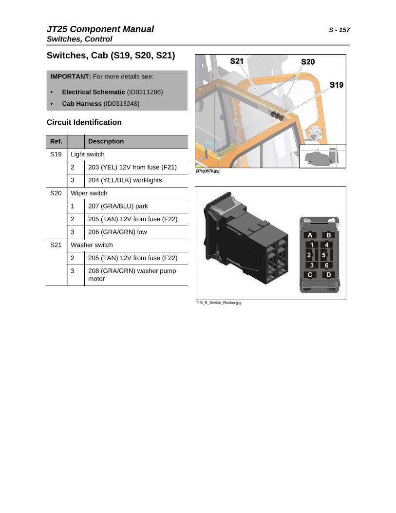
JT25 Component Manual S - 157Switches, Control
Switches, Cab (S19, S20, S21)
Circuit Identification
IMPORTANT: For more details see:
• Electrical Schematic (ID0311286)
• Cab Harness (ID0313248)
Ref. Description
S19 Light switch
2 203 (YEL) 12V from fuse (F21)
3 204 (YEL/BLK) worklights
S20 Wiper switch
1 207 (GRA/BLU) park
2 205 (TAN) 12V from fuse (F22)
3 206 (GRA/GRN) low
S21 Washer switch
2 205 (TAN) 12V from fuse (F22)
3 208 (GRA/GRN) washer pump motor
S - 158 JT25 Component ManualSwitches, Control
Switch, Seat (S6)
The normally open seat switch is located in the operator seat. When the operator is seated (switch closed) 12V is sent from the seat switch to the console engine start switch, seat indicator, and track override enable relay coil.
Circuit Identification
IMPORTANT: For more details see:
• Electrical Schematic (ID0311286)
• Operator Station Right Harness (ID0313234)
Ref. Description
A 97 (BLU/YEL) engine start switch on console, indicator, controller
B 13 (ORG/GRN) 12V from fuse (F16)
JT25 Component Manual S - 159Switches, Control
Switch, Throttle (S7)
Circuit Identification
IMPORTANT: For more details see:
• Electrical Schematic (ID0311286)
• Electrical Mounting Center (ID0312090)
• Frame Harness (ID0313263)
Ref. Description
1 157 (PUR/ORG) controller
2 27 (BLK/YEL) controller
3 156 (BLU/ORG) controller
S - 160 JT25 Component ManualSwitches, Control
Switch, Tracker Control Key (S18)
The tracker control key switch is located on the electrical mounting center under the hood. The tracker control relay latches as the tracker control key switch is closed, enabling the system.
Key is removable and strobe flashes when tracker control is activated but not synchronized with a tracker.
Key is not removable when tracker control is deactivated.
When strobe is flashing, unit will not thrust or rotate.
For information on tracker display see “Display, Tracker Control (U2)” on page 39.
Circuit Identification
IMPORTANT: For more details see:
• Electrical Schematic (ID0311286)
• Electrical Mounting Center (ID0312090
Ref. Description
A 103 (TAN/RED) tracker control relay and remote display
B 1A (BLK/RED) medium load ground
JT25 Component Manual S - 161Switches, Control
Switch, Worklight (S5)
Circuit Identification
IMPORTANT: For more details see:
• Electrical Schematic (ID0311286)
• Frame Harness (ID0313263)
Ref. Description
1 12 (ORG) 12V from fuse (F11)
4 59 (TAN/RED) worklight relay
5 72 (TAN/GRN) hydraulic gauges
6 12 (ORG) 12V from fuse (F11)
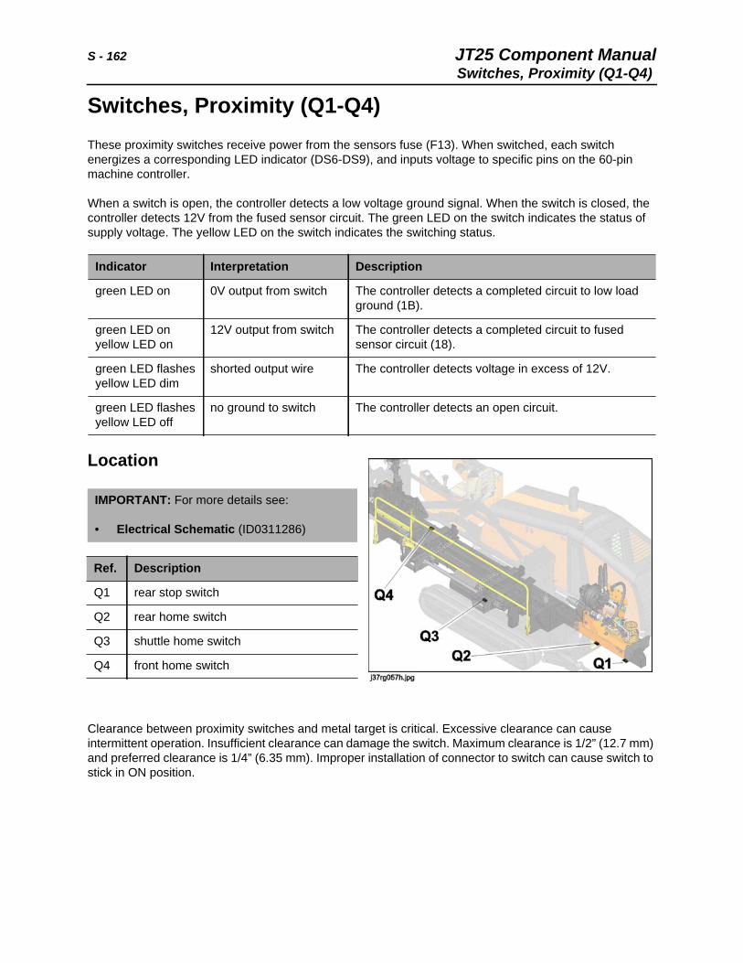
S - 162 JT25 Component ManualSwitches, Proximity (Q1-Q4)
Switches, Proximity (Q1-Q4)These proximity switches receive power from the sensors fuse (F13). When switched, each switch energizes a corresponding LED indicator (DS6-DS9), and inputs voltage to specific pins on the 60-pin machine controller.
When a switch is open, the controller detects a low voltage ground signal. When the switch is closed, the controller detects 12V from the fused sensor circuit. The green LED on the switch indicates the status of supply voltage. The yellow LED on the switch indicates the switching status.
Location
Clearance between proximity switches and metal target is critical. Excessive clearance can cause intermittent operation. Insufficient clearance can damage the switch. Maximum clearance is 1/2” (12.7 mm) and preferred clearance is 1/4” (6.35 mm). Improper installation of connector to switch can cause switch to stick in ON position.
Indicator Interpretation Description
green LED on 0V output from switch The controller detects a completed circuit to low load ground (1B).
green LED onyellow LED on
12V output from switch The controller detects a completed circuit to fused sensor circuit (18).
green LED flashesyellow LED dim
shorted output wire The controller detects voltage in excess of 12V.
green LED flashesyellow LED off
no ground to switch The controller detects an open circuit.
IMPORTANT: For more details see:
• Electrical Schematic (ID0311286)
Ref. Description
Q1 rear stop switch
Q2 rear home switch
Q3 shuttle home switch
Q4 front home switch
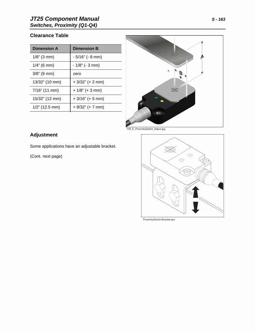
JT25 Component Manual S - 163Switches, Proximity (Q1-Q4)
Clearance Table
Adjustment
Some applications have an adjustable bracket.
(Cont. next page)
Dimension A Dimension B
1/8” (3 mm) - 5/16” (- 8 mm)
1/4” (6 mm) - 1/8” (- 3 mm)
3/8” (9 mm) zero
13/32” (10 mm) + 3/32” (+ 2 mm)
7/16” (11 mm) + 1/8” (+ 3 mm)
15/32” (12 mm) + 3/16” (+ 5 mm)
1/2” (12.5 mm) + 9/32” (+ 7 mm)
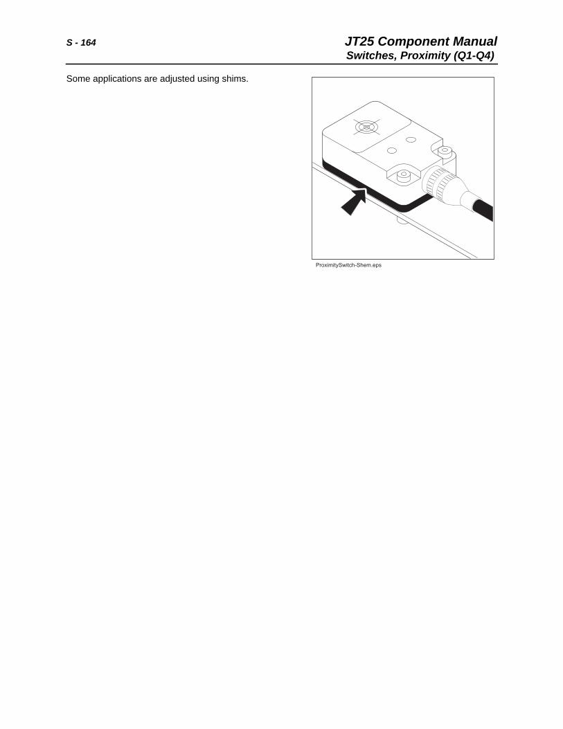
S - 164 JT25 Component ManualSwitches, Proximity (Q1-Q4)
Some applications are adjusted using shims.
JT25 Component Manual T, U - 165Switches, Proximity (Q1-Q4)
T, U
Chapter Contents
Tank, Fuel . . . . . . . . . . . . . . . . . . . . . . . . . . . . . . . 166
Test Ports and Hydraulic Adjustments. . . . . . . . 167
Timer Delay, Manual Drive . . . . . . See Control Units
Track Components . . . . . . . . . . . . . . . . . . . . . . . . 175
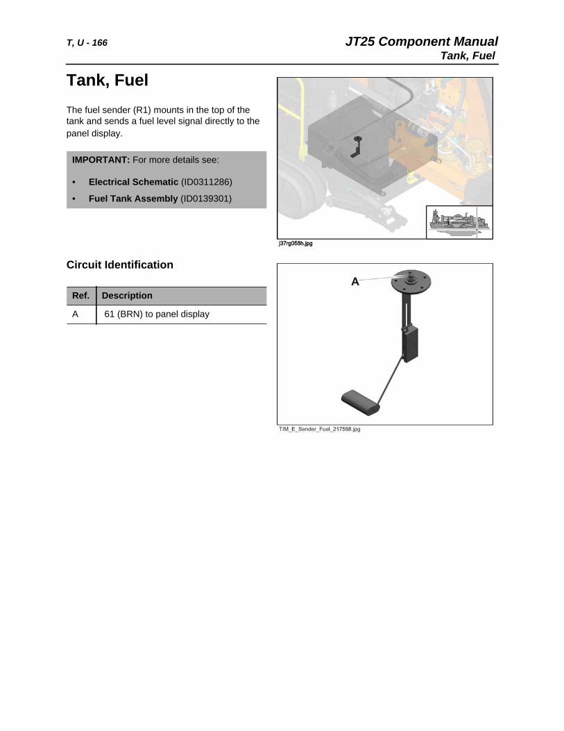
T, U - 166 JT25 Component ManualTank, Fuel
Tank, Fuel The fuel sender (R1) mounts in the top of the tank and sends a fuel level signal directly to the panel display.
Circuit Identification
IMPORTANT: For more details see:
• Electrical Schematic (ID0311286)
• Fuel Tank Assembly (ID0139301)
Ref. Description
A 61 (BRN) to panel display
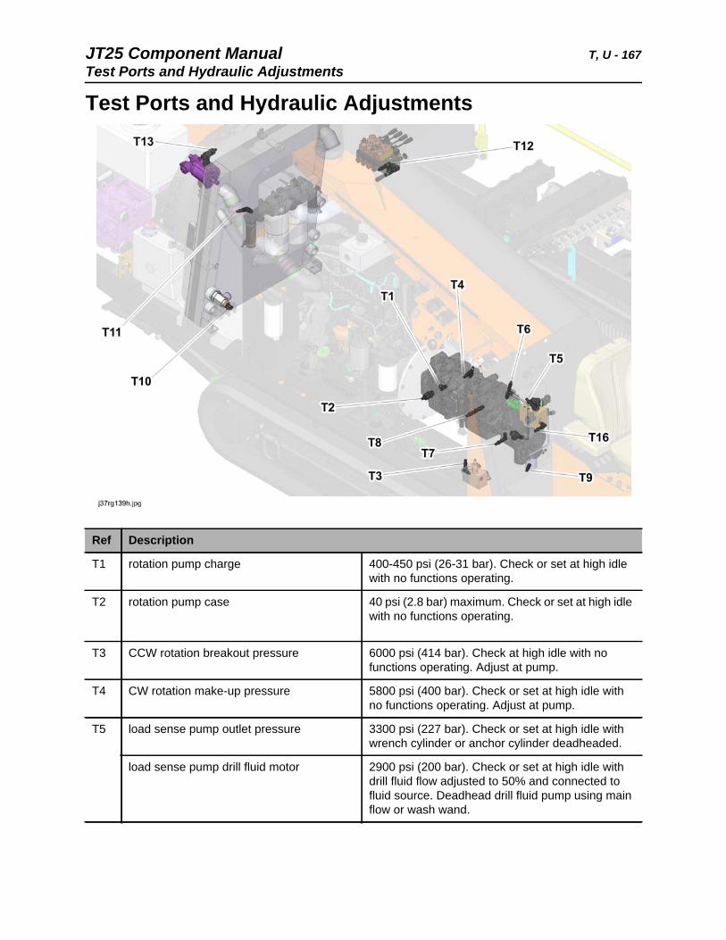
JT25 Component Manual T, U - 167Test Ports and Hydraulic Adjustments
Test Ports and Hydraulic Adjustments
Ref Description
T1 rotation pump charge 400-450 psi (26-31 bar). Check or set at high idle with no functions operating.
T2 rotation pump case 40 psi (2.8 bar) maximum. Check or set at high idle with no functions operating.
T3 CCW rotation breakout pressure 6000 psi (414 bar). Check at high idle with no functions operating. Adjust at pump.
T4 CW rotation make-up pressure 5800 psi (400 bar). Check or set at high idle with no functions operating. Adjust at pump.
T5 load sense pump outlet pressure 3300 psi (227 bar). Check or set at high idle with wrench cylinder or anchor cylinder deadheaded.
load sense pump drill fluid motor 2900 psi (200 bar). Check or set at high idle with drill fluid flow adjusted to 50% and connected to fluid source. Deadhead drill fluid pump using main flow or wash wand.
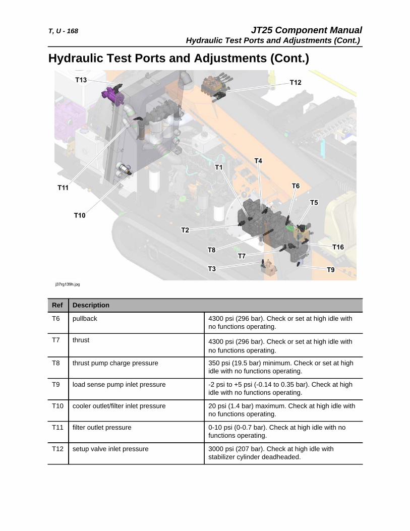
T, U - 168 JT25 Component ManualHydraulic Test Ports and Adjustments (Cont.)
Hydraulic Test Ports and Adjustments (Cont.)
Ref Description
T6 pullback 4300 psi (296 bar). Check or set at high idle with no functions operating.
T7 thrust 4300 psi (296 bar). Check or set at high idle with no functions operating.
T8 thrust pump charge pressure 350 psi (19.5 bar) minimum. Check or set at high idle with no functions operating.
T9 load sense pump inlet pressure -2 psi to +5 psi (-0.14 to 0.35 bar). Check at high idle with no functions operating.
T10 cooler outlet/filter inlet pressure 20 psi (1.4 bar) maximum. Check at high idle with no functions operating.
T11 filter outlet pressure 0-10 psi (0-0.7 bar). Check at high idle with no functions operating.
T12 setup valve inlet pressure 3000 psi (207 bar). Check at high idle with stabilizer cylinder deadheaded.

JT25 Component Manual T, U - 169Hydraulic Test Ports and Adjustments (Cont.)
T13 fan motor pressure 3000 psi (207 bar) maximum, varies with fan speed. Check at high idle with no functions operating.
T14 right anchor cylinder up pressure 1600 psi (110 bar). Check at high idle with no functions operating.
T15 left anchor cylinder up pressure 1600 psi (110 bar). Check at high idle with no functions operating.
T16 load sense pump outlet pressure 240 psi (17 bar) differential pressure. Check at high idle with drill fluid flow at 17 gpm (64 L/min).
T17 carriage charge pressure 260 psi (18 bar). Check at high idle with no functions operating.
Ref Description
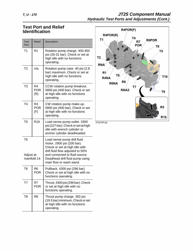
T, U - 170 JT25 Component ManualHydraulic Test Ports and Adjustments (Cont.)
Test Port and Relief Identification
Test Port
Relief Description
T1 R1 Rotation pump charge. 400-450 psi (26-31 bar). Check or set at high idle with no functions operating.
T2 n/a Rotation pump case. 40 psi (2.8 bar) maximum. Check or set at high idle with no functions operating.
T3 R4 POR (R)
CCW rotation pump breakout. 5800 psi (400 bar). Check or set at high idle with no functions operating.
T4 R4 POR (F)
CW rotation pump make-up. 5800 psi (400 bar). Check or set at high idle with no functions operating.
T5 R16 Load sense pump outlet. 3300 psi (227 bar). Check or set at high idle with wrench cylinder or anchor cylinder deadheaded.
T5
Adjust at manifold 14
Load sense pump drill fluid motor. 2900 psi (200 bar). Check or set at high idle with drill fluid flow adjusted to 50% and connected to fluid source. Deadhead drill fluid pump using main flow or wash wand.
T6 R6 POR
Pullback. 4300 psi (296 bar). Check or set at high idle with no functions operating.
T7 R7 POR
Thrust. 4300 psi (296 bar). Check or set at high idle with no functions operating.
T8 R8 Thrust pump charge. 350 psi (19.5 bar) minimum. Check or set at high idle with no functions operating.
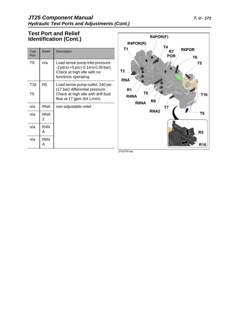
JT25 Component Manual T, U - 171Hydraulic Test Ports and Adjustments (Cont.)
Test Port and Relief Identification (Cont.)
Test Port
Relief Description
T9 n/a Load sense pump inlet pressure. -2 psi to +5 psi (-0.14 to 0.35 bar). Check at high idle with no functions operating.
T16
T5
R5 Load sense pump outlet. 240 psi (17 bar) differential pressure. Check at high idle with drill fluid flow at 17 gpm (64 L/min).
n/a RNA non-adjustable relief
n/a RNA 2
n/a R4NA
n/a R6NA
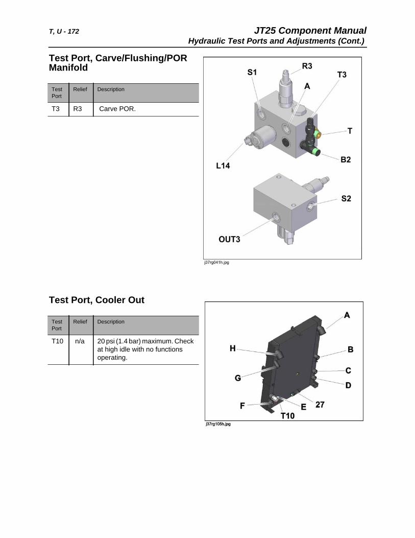
T, U - 172 JT25 Component ManualHydraulic Test Ports and Adjustments (Cont.)
Test Port, Carve/Flushing/POR Manifold
Test Port, Cooler Out
Test Port
Relief Description
T3 R3 Carve POR.
Test Port
Relief Description
T10 n/a 20 psi (1.4 bar) maximum. Check at high idle with no functions operating.
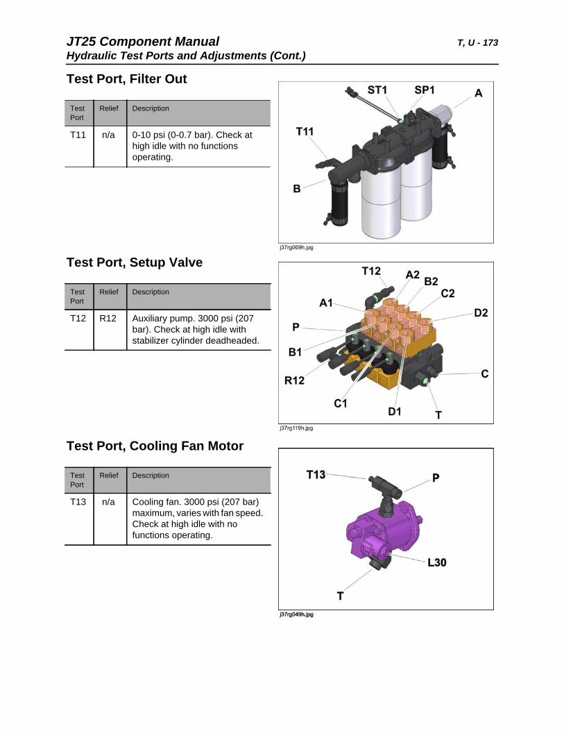
JT25 Component Manual T, U - 173Hydraulic Test Ports and Adjustments (Cont.)
Test Port, Filter Out
Test Port, Setup Valve
Test Port, Cooling Fan Motor
Test Port
Relief Description
T11 n/a 0-10 psi (0-0.7 bar). Check at high idle with no functions operating.
Test Port
Relief Description
T12 R12 Auxiliary pump. 3000 psi (207 bar). Check at high idle with stabilizer cylinder deadheaded.
Test Port
Relief Description
T13 n/a Cooling fan. 3000 psi (207 bar) maximum, varies with fan speed. Check at high idle with no functions operating.
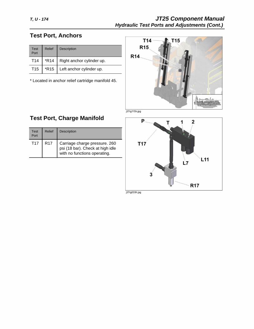
T, U - 174 JT25 Component ManualHydraulic Test Ports and Adjustments (Cont.)
Test Port, Anchors
* Located in anchor relief cartridge manifold 45.
Test Port, Charge Manifold
Test Port
Relief Description
T14 *R14 Right anchor cylinder up.
T15 *R15 Left anchor cylinder up.
Test Port
Relief Description
T17 R17 Carriage charge pressure. 260 psi (18 bar). Check at high idle with no functions operating.
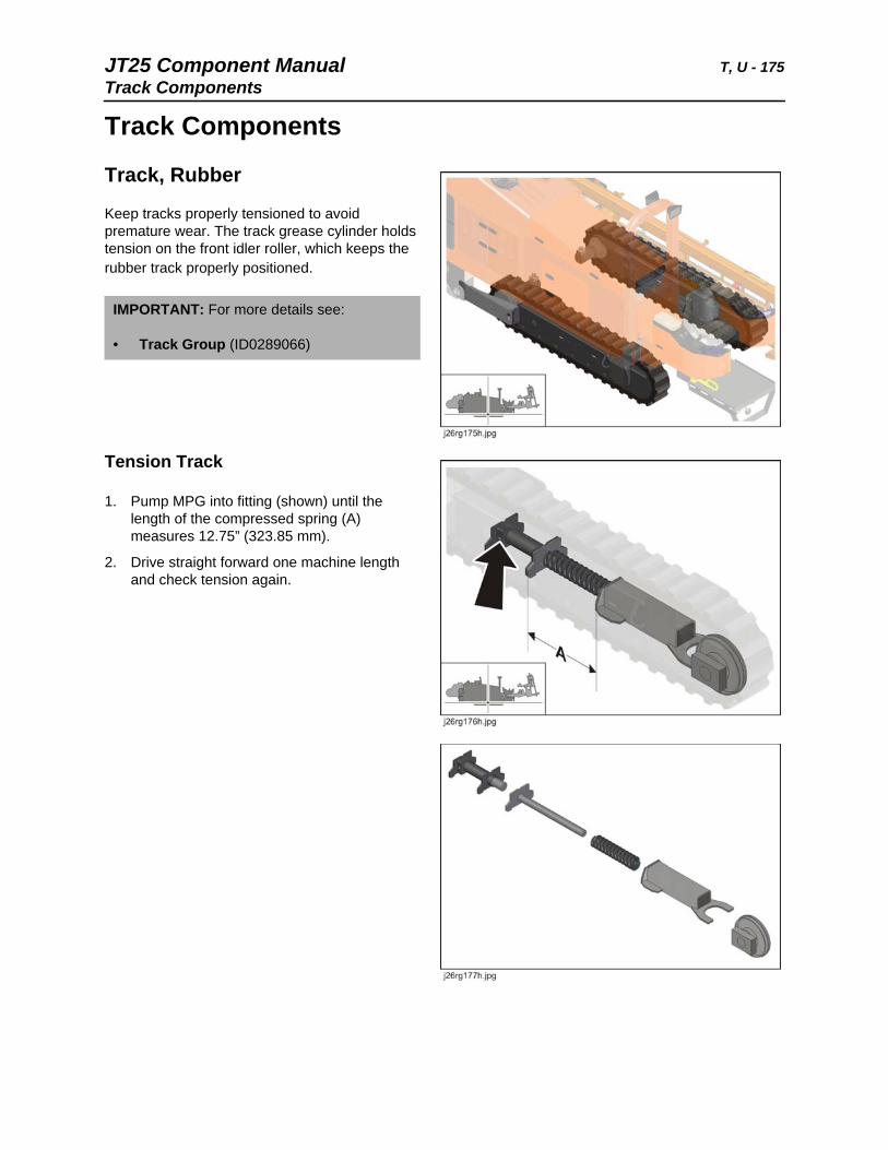
JT25 Component Manual T, U - 175Track Components
Track Components
Track, Rubber
Keep tracks properly tensioned to avoid premature wear. The track grease cylinder holds tension on the front idler roller, which keeps the rubber track properly positioned.
Tension Track
1. Pump MPG into fitting (shown) until the length of the compressed spring (A) measures 12.75” (323.85 mm).
2. Drive straight forward one machine length and check tension again.
IMPORTANT: For more details see:
• Track Group (ID0289066)
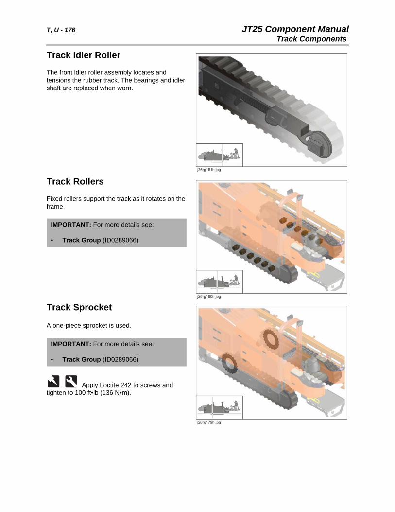
T, U - 176 JT25 Component ManualTrack Components
Track Idler Roller
The front idler roller assembly locates and tensions the rubber track. The bearings and idler shaft are replaced when worn.
Track Rollers
Fixed rollers support the track as it rotates on the frame.
Track Sprocket
A one-piece sprocket is used.
Apply Loctite 242 to screws and tighten to 100 ft•lb (136 N•m).
IMPORTANT: For more details see:
• Track Group (ID0289066)
IMPORTANT: For more details see:
• Track Group (ID0289066)
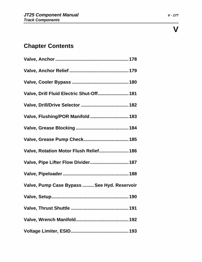
JT25 Component Manual V - 177Track Components
V
Chapter Contents
Valve, Anchor .........................................................178
Valve, Anchor Relief ..............................................179
Valve, Cooler Bypass ............................................180
Valve, Drill Fluid Electric Shut-Off........................181
Valve, Drill/Drive Selector .....................................182
Valve, Flushing/POR Manifold ..............................183
Valve, Grease Blocking .........................................184
Valve, Grease Pump Check...................................185
Valve, Rotation Motor Flush Relief.......................186
Valve, Pipe Lifter Flow Divider..............................187
Valve, Pipeloader ...................................................188
Valve, Pump Case Bypass ......... See Hyd. Reservoir
Valve, Setup............................................................190
Valve, Thrust Shuttle .............................................191
Valve, Wrench Manifold.........................................192
Voltage Limiter, ESID.............................................193
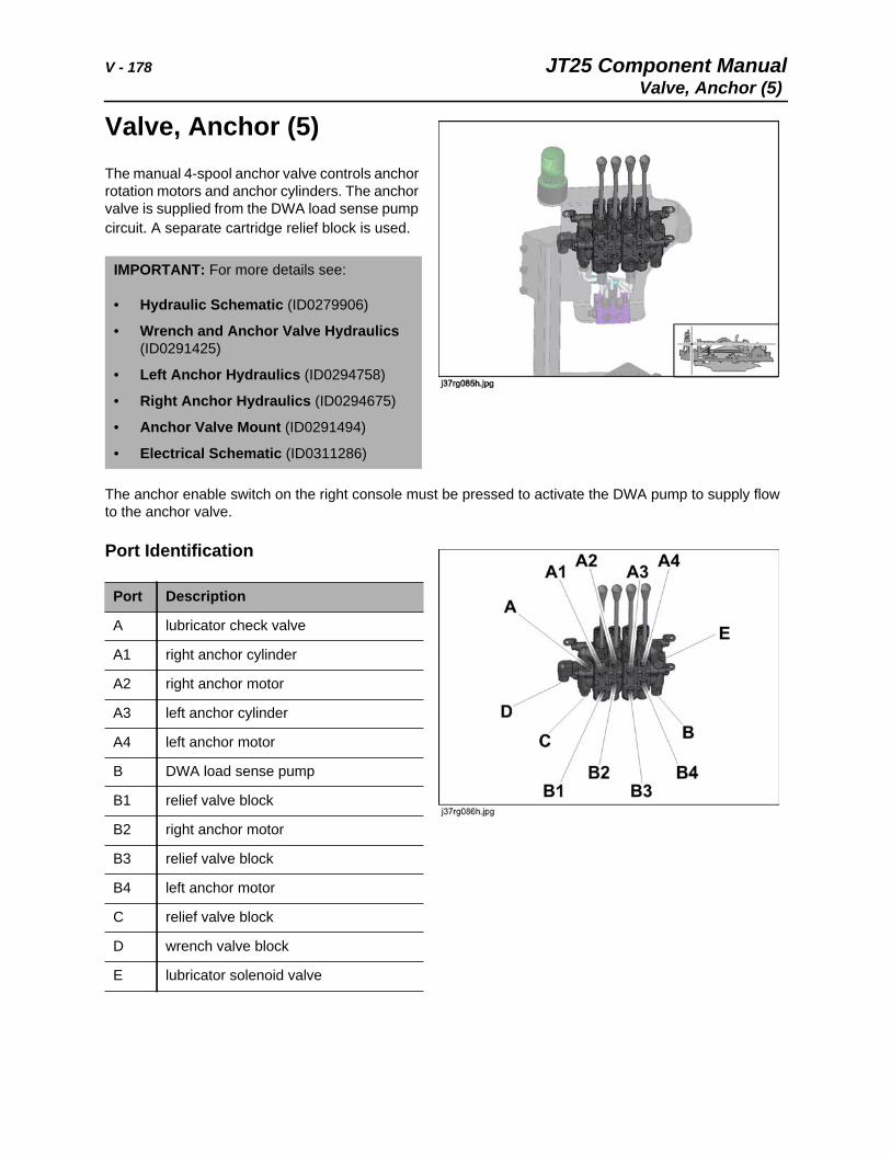
V - 178 JT25 Component ManualValve, Anchor (5)
Valve, Anchor (5)The manual 4-spool anchor valve controls anchor rotation motors and anchor cylinders. The anchor valve is supplied from the DWA load sense pump circuit. A separate cartridge relief block is used.
The anchor enable switch on the right console must be pressed to activate the DWA pump to supply flow to the anchor valve.
Port Identification
IMPORTANT: For more details see:
• Hydraulic Schematic (ID0279906)
• Wrench and Anchor Valve Hydraulics (ID0291425)
• Left Anchor Hydraulics (ID0294758)
• Right Anchor Hydraulics (ID0294675)
• Anchor Valve Mount (ID0291494)
• Electrical Schematic (ID0311286)
Port Description
A lubricator check valve
A1 right anchor cylinder
A2 right anchor motor
A3 left anchor cylinder
A4 left anchor motor
B DWA load sense pump
B1 relief valve block
B2 right anchor motor
B3 relief valve block
B4 left anchor motor
C relief valve block
D wrench valve block
E lubricator solenoid valve
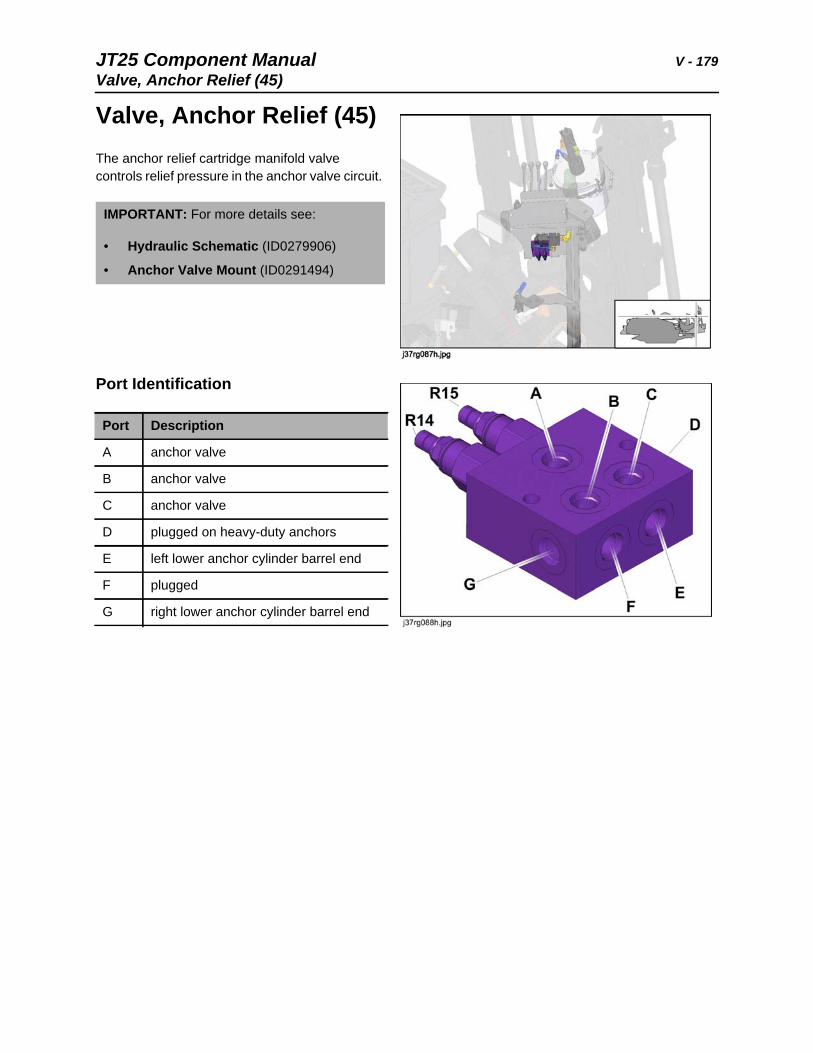
JT25 Component Manual V - 179Valve, Anchor Relief (45)
Valve, Anchor Relief (45)The anchor relief cartridge manifold valve controls relief pressure in the anchor valve circuit.
Port Identification
IMPORTANT: For more details see:
• Hydraulic Schematic (ID0279906)
• Anchor Valve Mount (ID0291494)
Port Description
A anchor valve
B anchor valve
C anchor valve
D plugged on heavy-duty anchors
E left lower anchor cylinder barrel end
F plugged
G right lower anchor cylinder barrel end
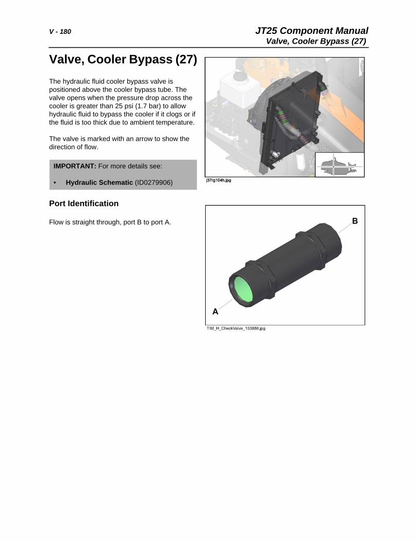
V - 180 JT25 Component ManualValve, Cooler Bypass (27)
Valve, Cooler Bypass (27)The hydraulic fluid cooler bypass valve is positioned above the cooler bypass tube. The valve opens when the pressure drop across the cooler is greater than 25 psi (1.7 bar) to allow hydraulic fluid to bypass the cooler if it clogs or if the fluid is too thick due to ambient temperature.
The valve is marked with an arrow to show the direction of flow.
Port Identification
Flow is straight through, port B to port A.
IMPORTANT: For more details see:
• Hydraulic Schematic (ID0279906)
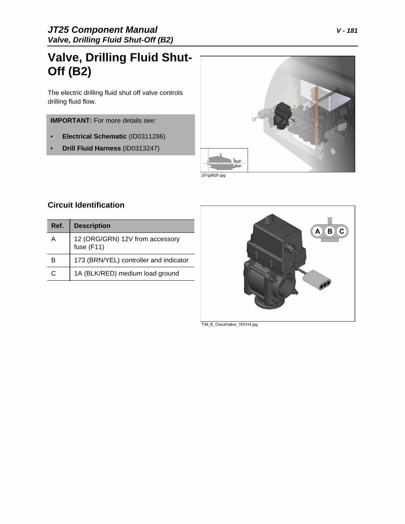
JT25 Component Manual V - 181Valve, Drilling Fluid Shut-Off (B2)
Valve, Drilling Fluid Shut-Off (B2)The electric drilling fluid shut off valve controls drilling fluid flow.
Circuit Identification
IMPORTANT: For more details see:
• Electrical Schematic (ID0311286)
• Drill Fluid Harness (ID0313247)
Ref. Description
A 12 (ORG/GRN) 12V from accessory fuse (F11)
B 173 (BRN/YEL) controller and indicator
C 1A (BLK/RED) medium load ground
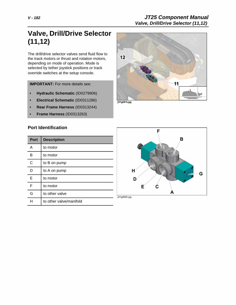
V - 182 JT25 Component ManualValve, Drill/Drive Selector (11,12)
Valve, Drill/Drive Selector (11,12)The drill/drive selector valves send fluid flow to the track motors or thrust and rotation motors, depending on mode of operation. Mode is selected by tether joystick positions or track override switches at the setup console.
Port Identification
IMPORTANT: For more details see:
• Hydraulic Schematic (ID0279906)
• Electrical Schematic (ID0311286)
• Rear Frame Harness (ID0313244)
• Frame Harness (ID0313263)
Port Description
A to motor
B to motor
C to B on pump
D to A on pump
E to motor
F to motor
G to other valve
H to other valve/manifold
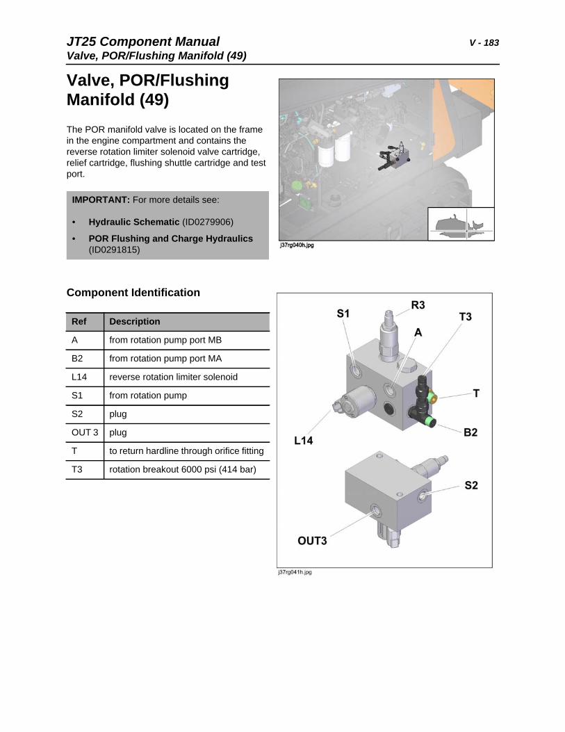
JT25 Component Manual V - 183Valve, POR/Flushing Manifold (49)
Valve, POR/Flushing Manifold (49)The POR manifold valve is located on the frame in the engine compartment and contains the reverse rotation limiter solenoid valve cartridge, relief cartridge, flushing shuttle cartridge and test port.
Component Identification
IMPORTANT: For more details see:
• Hydraulic Schematic (ID0279906)
• POR Flushing and Charge Hydraulics (ID0291815)
Ref Description
A from rotation pump port MB
B2 from rotation pump port MA
L14 reverse rotation limiter solenoid
S1 from rotation pump
S2 plug
OUT 3 plug
T to return hardline through orifice fitting
T3 rotation breakout 6000 psi (414 bar)
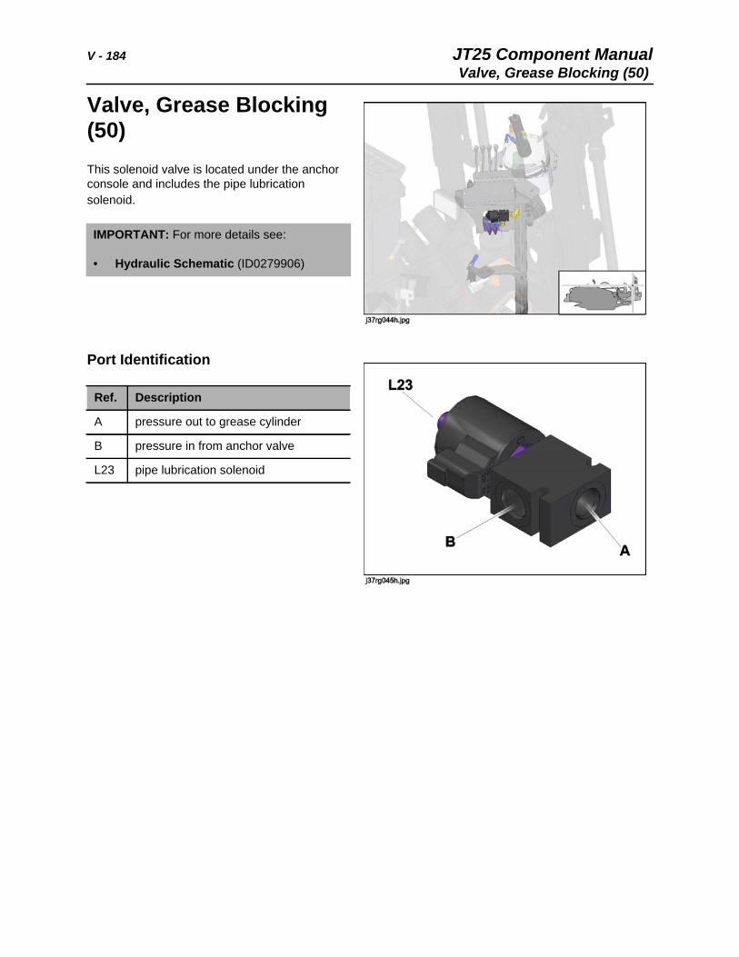
V - 184 JT25 Component ManualValve, Grease Blocking (50)
Valve, Grease Blocking (50)This solenoid valve is located under the anchor console and includes the pipe lubrication solenoid.
Port Identification
IMPORTANT: For more details see:
• Hydraulic Schematic (ID0279906)
Ref. Description
A pressure out to grease cylinder
B pressure in from anchor valve
L23 pipe lubrication solenoid
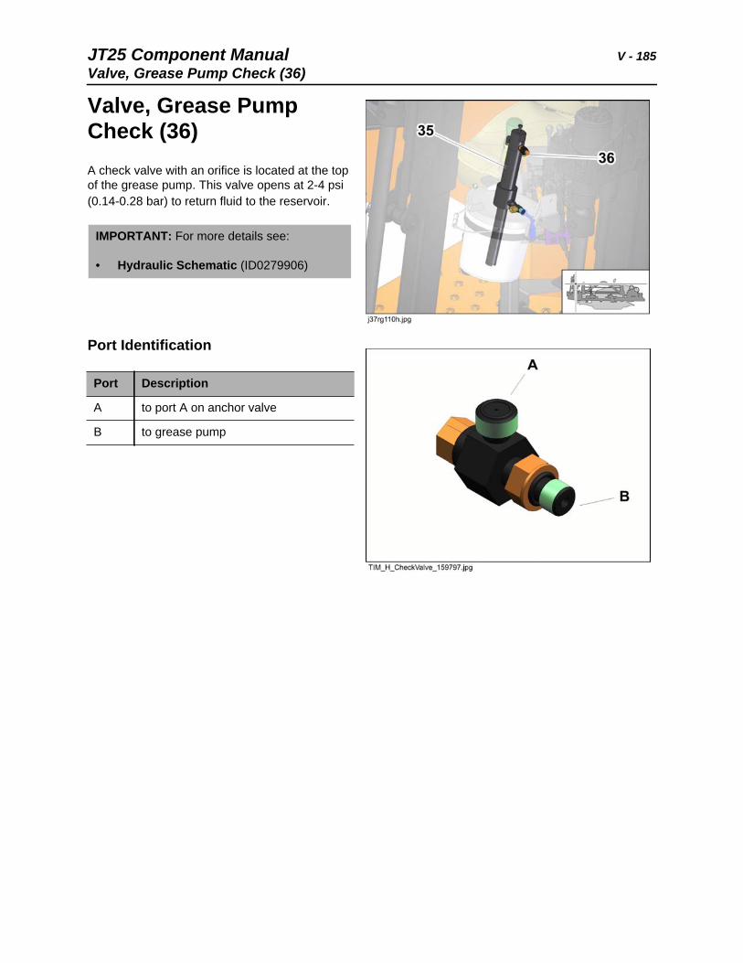
JT25 Component Manual V - 185Valve, Grease Pump Check (36)
Valve, Grease Pump Check (36)A check valve with an orifice is located at the top of the grease pump. This valve opens at 2-4 psi (0.14-0.28 bar) to return fluid to the reservoir.
Port Identification
IMPORTANT: For more details see:
• Hydraulic Schematic (ID0279906)
Port Description
A to port A on anchor valve
B to grease pump
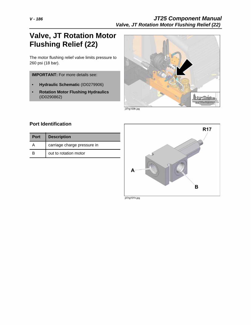
V - 186 JT25 Component ManualValve, JT Rotation Motor Flushing Relief (22)
Valve, JT Rotation Motor Flushing Relief (22)The motor flushing relief valve limits pressure to 260 psi (18 bar).
Port Identification
IMPORTANT: For more details see:
• Hydraulic Schematic (ID0279906)
• Rotation Motor Flushing Hydraulics (ID0290862)
Port Description
A carriage charge pressure in
B out to rotation motor
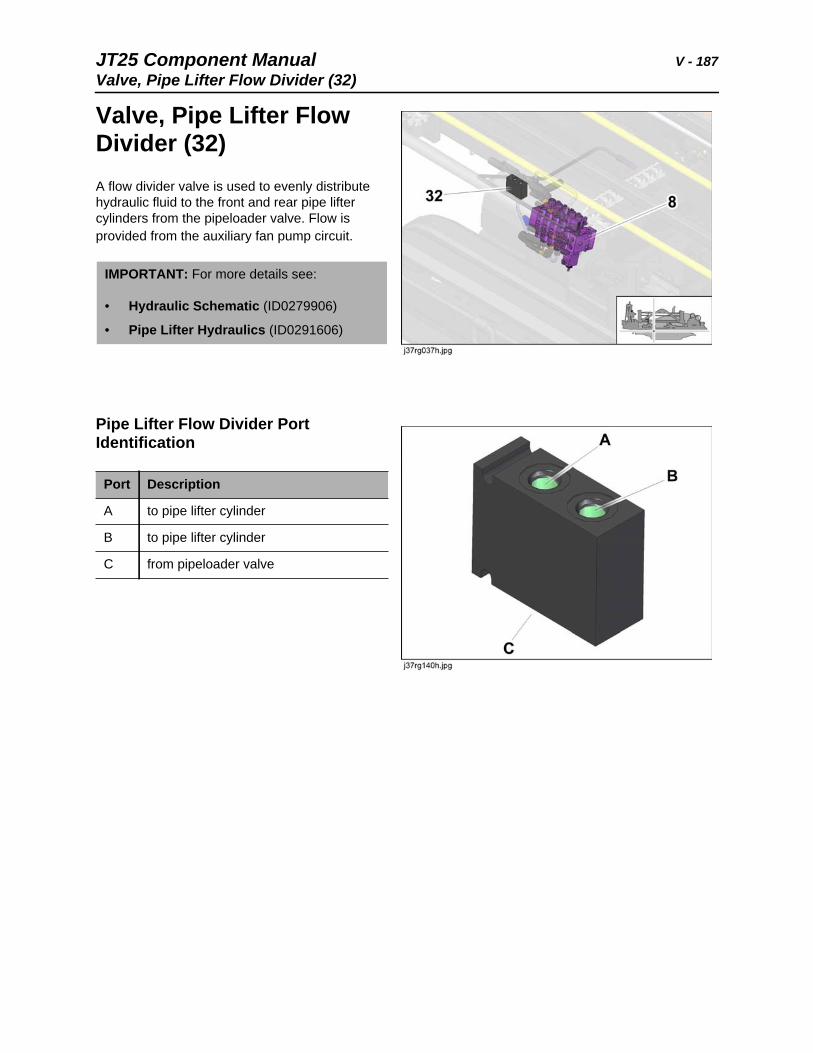
JT25 Component Manual V - 187Valve, Pipe Lifter Flow Divider (32)
Valve, Pipe Lifter Flow Divider (32) A flow divider valve is used to evenly distribute hydraulic fluid to the front and rear pipe lifter cylinders from the pipeloader valve. Flow is provided from the auxiliary fan pump circuit.
Pipe Lifter Flow Divider Port Identification
IMPORTANT: For more details see:
• Hydraulic Schematic (ID0279906)
• Pipe Lifter Hydraulics (ID0291606)
Port Description
A to pipe lifter cylinder
B to pipe lifter cylinder
C from pipeloader valve
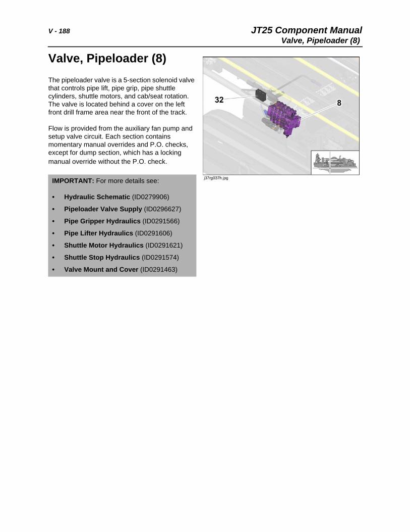
V - 188 JT25 Component ManualValve, Pipeloader (8)
Valve, Pipeloader (8)The pipeloader valve is a 5-section solenoid valve that controls pipe lift, pipe grip, pipe shuttle cylinders, shuttle motors, and cab/seat rotation. The valve is located behind a cover on the left front drill frame area near the front of the track.
Flow is provided from the auxiliary fan pump and setup valve circuit. Each section contains momentary manual overrides and P.O. checks, except for dump section, which has a locking manual override without the P.O. check.
IMPORTANT: For more details see:
• Hydraulic Schematic (ID0279906)
• Pipeloader Valve Supply (ID0296627)
• Pipe Gripper Hydraulics (ID0291566)
• Pipe Lifter Hydraulics (ID0291606)
• Shuttle Motor Hydraulics (ID0291621)
• Shuttle Stop Hydraulics (ID0291574)
• Valve Mount and Cover (ID0291463)
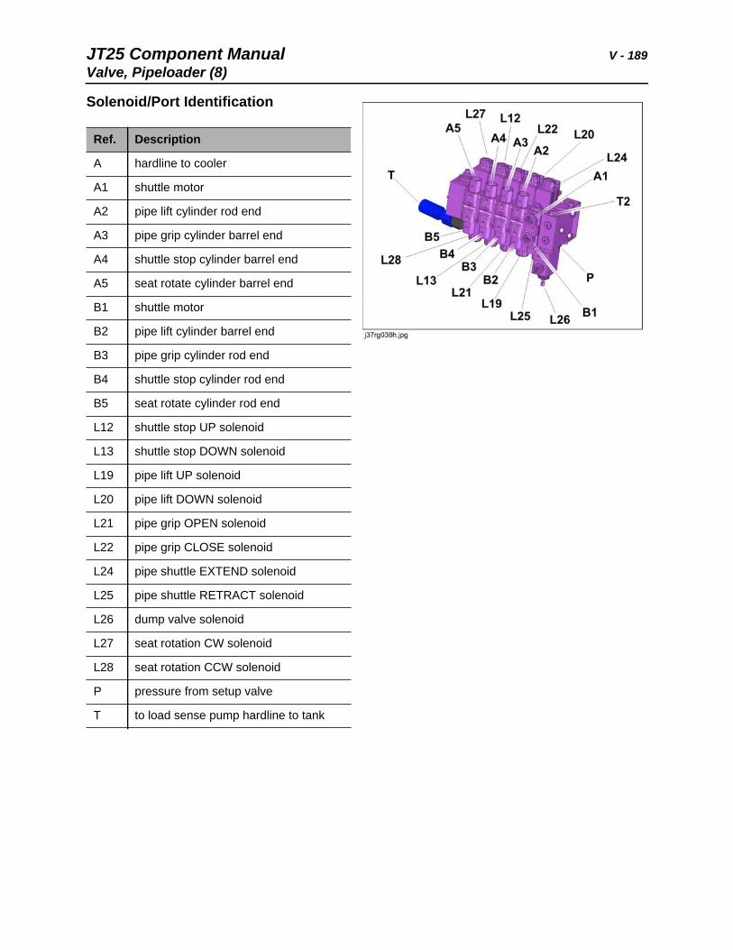
JT25 Component Manual V - 189Valve, Pipeloader (8)
Solenoid/Port Identification
Ref. Description
A hardline to cooler
A1 shuttle motor
A2 pipe lift cylinder rod end
A3 pipe grip cylinder barrel end
A4 shuttle stop cylinder barrel end
A5 seat rotate cylinder barrel end
B1 shuttle motor
B2 pipe lift cylinder barrel end
B3 pipe grip cylinder rod end
B4 shuttle stop cylinder rod end
B5 seat rotate cylinder rod end
L12 shuttle stop UP solenoid
L13 shuttle stop DOWN solenoid
L19 pipe lift UP solenoid
L20 pipe lift DOWN solenoid
L21 pipe grip OPEN solenoid
L22 pipe grip CLOSE solenoid
L24 pipe shuttle EXTEND solenoid
L25 pipe shuttle RETRACT solenoid
L26 dump valve solenoid
L27 seat rotation CW solenoid
L28 seat rotation CCW solenoid
P pressure from setup valve
T to load sense pump hardline to tank
V - 190 JT25 Component ManualValve, Setup (7)
Valve, Setup (7)The 4-spool manual setup valve controls hydraulic fluid from the auxiliary fan pump to the pipeloader valve, frame tilt (pivot) cylinders and stabilizer cylinders. Each of the sections has P.O. checks and orifices in the fittings. The setup valve includes test port T12. Test for 3000 psi (207 bar) with stabilizer cylinder deadheaded.
Port Identification
IMPORTANT: For more details see:
• Hydraulic Schematic (ID0279906)
• Setup Valve (ID0292278)
Port Description
A1 pivot cylinder rod end
A2 pivot cylinder barrel end
B1 pivot cylinder barrel end
B2 pivot cylinder rod end
C pipeloader valve
C1 stabilizer cylinder barrel end
C2 stabilizer cylinder rod end
D1 stabilizer cylinder barrel end
D2 stabilizer cylinder rod end
P auxiliary pump
T power beyond to pipeloader valve
T12 test port 3000 psi (207 bar) stabilizer cylinder deadheaded
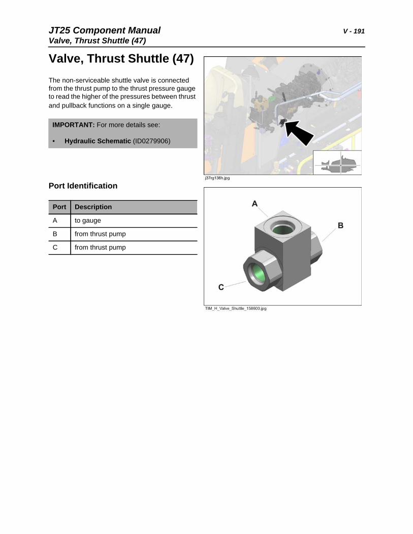
JT25 Component Manual V - 191Valve, Thrust Shuttle (47)
Valve, Thrust Shuttle (47) The non-serviceable shuttle valve is connected from the thrust pump to the thrust pressure gauge to read the higher of the pressures between thrust and pullback functions on a single gauge.
Port Identification
IMPORTANT: For more details see:
• Hydraulic Schematic (ID0279906)
Port Description
A to gauge
B from thrust pump
C from thrust pump
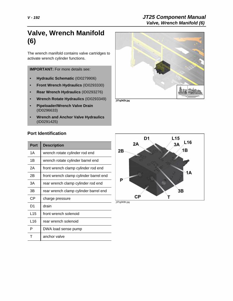
V - 192 JT25 Component ManualValve, Wrench Manifold (6)
Valve, Wrench Manifold (6)The wrench manifold contains valve cartridges to activate wrench cylinder functions.
Port Identification
IMPORTANT: For more details see:
• Hydraulic Schematic (ID0279906)
• Front Wrench Hydraulics (ID0293330)
• Rear Wrench Hydraulics (ID0293276)
• Wrench Rotate Hydraulics (ID0293349)
• Pipeloader/Wrench Valve Drain (ID0296633)
• Wrench and Anchor Valve Hydraulics (ID0291425)
Port Description
1A wrench rotate cylinder rod end
1B wrench rotate cylinder barrel end
2A front wrench clamp cylinder rod end
2B front wrench clamp cylinder barrel end
3A rear wrench clamp cylinder rod end
3B rear wrench clamp cylinder barrel end
CP charge pressure
D1 drain
L15 front wrench solenoid
L16 rear wrench solenoid
P DWA load sense pump
T anchor valve
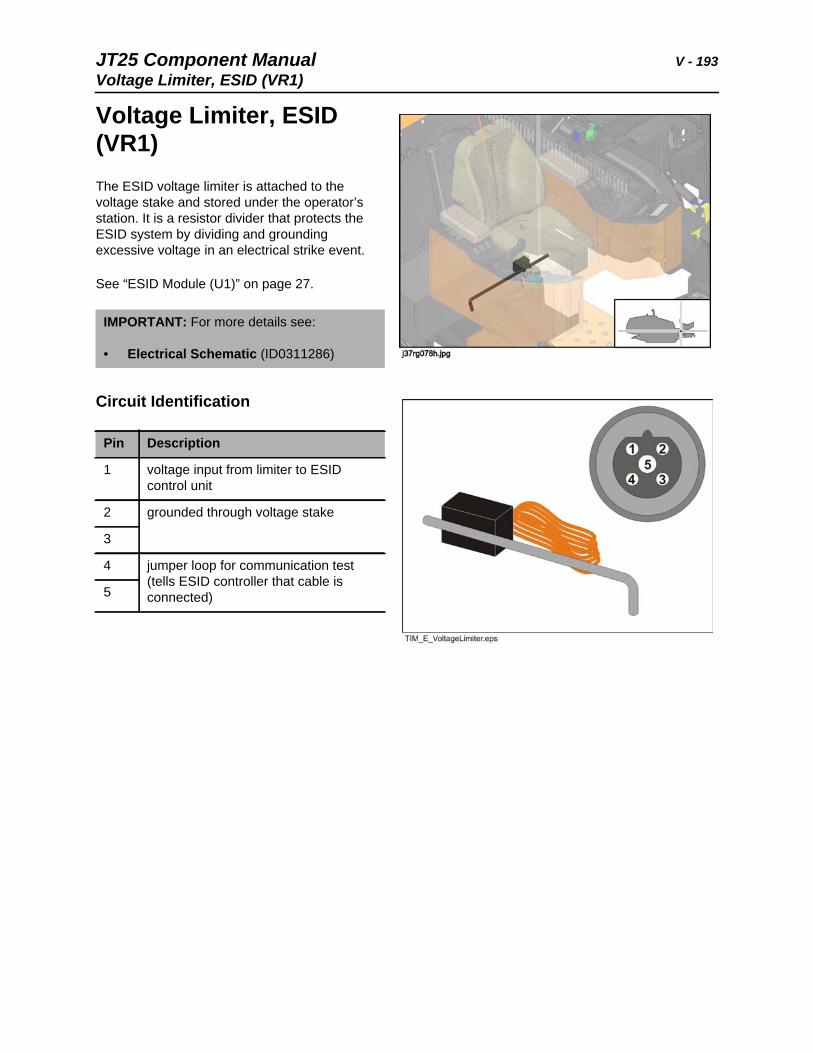
JT25 Component Manual V - 193Voltage Limiter, ESID (VR1)
Voltage Limiter, ESID (VR1)The ESID voltage limiter is attached to the voltage stake and stored under the operator’s station. It is a resistor divider that protects the ESID system by dividing and grounding excessive voltage in an electrical strike event.
See “ESID Module (U1)” on page 27.
Circuit Identification
IMPORTANT: For more details see:
• Electrical Schematic (ID0311286)
Pin Description
1 voltage input from limiter to ESID control unit
2 grounded through voltage stake
3
4 jumper loop for communication test (tells ESID controller that cable is connected)5

V - 194 JT25 Component ManualVoltage Limiter, ESID (VR1)
JT25 Component Manual W, X, Y, Z - 195
W, X, Y, Z
Chapter Contents
Washer Motor . . . . . . . . . . . . See Motors, Electrical
Wiper Motor . . . . . . . . . . . . . See Motors, Electrical
Worklights . . . . . . . . . . . . . . . . . . . . . . . . . . . . . . . 196
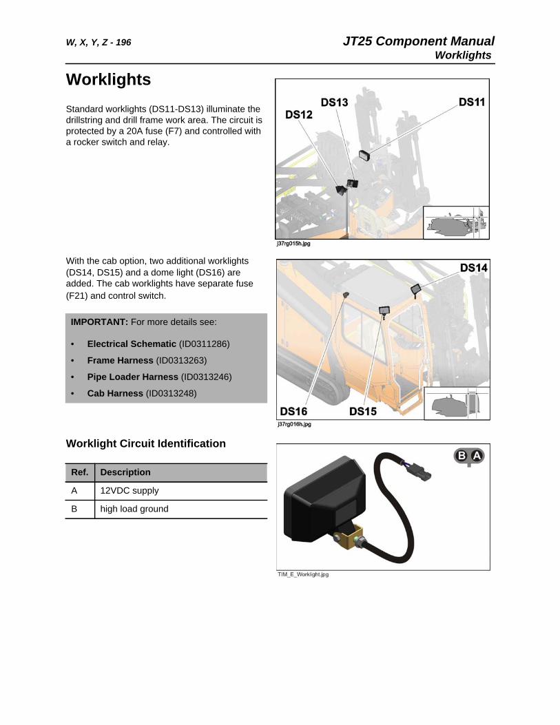
W, X, Y, Z - 196 JT25 Component ManualWorklights
WorklightsStandard worklights (DS11-DS13) illuminate the drillstring and drill frame work area. The circuit is protected by a 20A fuse (F7) and controlled with a rocker switch and relay.
With the cab option, two additional worklights (DS14, DS15) and a dome light (DS16) are added. The cab worklights have separate fuse (F21) and control switch.
Worklight Circuit Identification
IMPORTANT: For more details see:
• Electrical Schematic (ID0311286)
• Frame Harness (ID0313263)
• Pipe Loader Harness (ID0313246)
• Cab Harness (ID0313248)
Ref. Description
A 12VDC supply
B high load ground
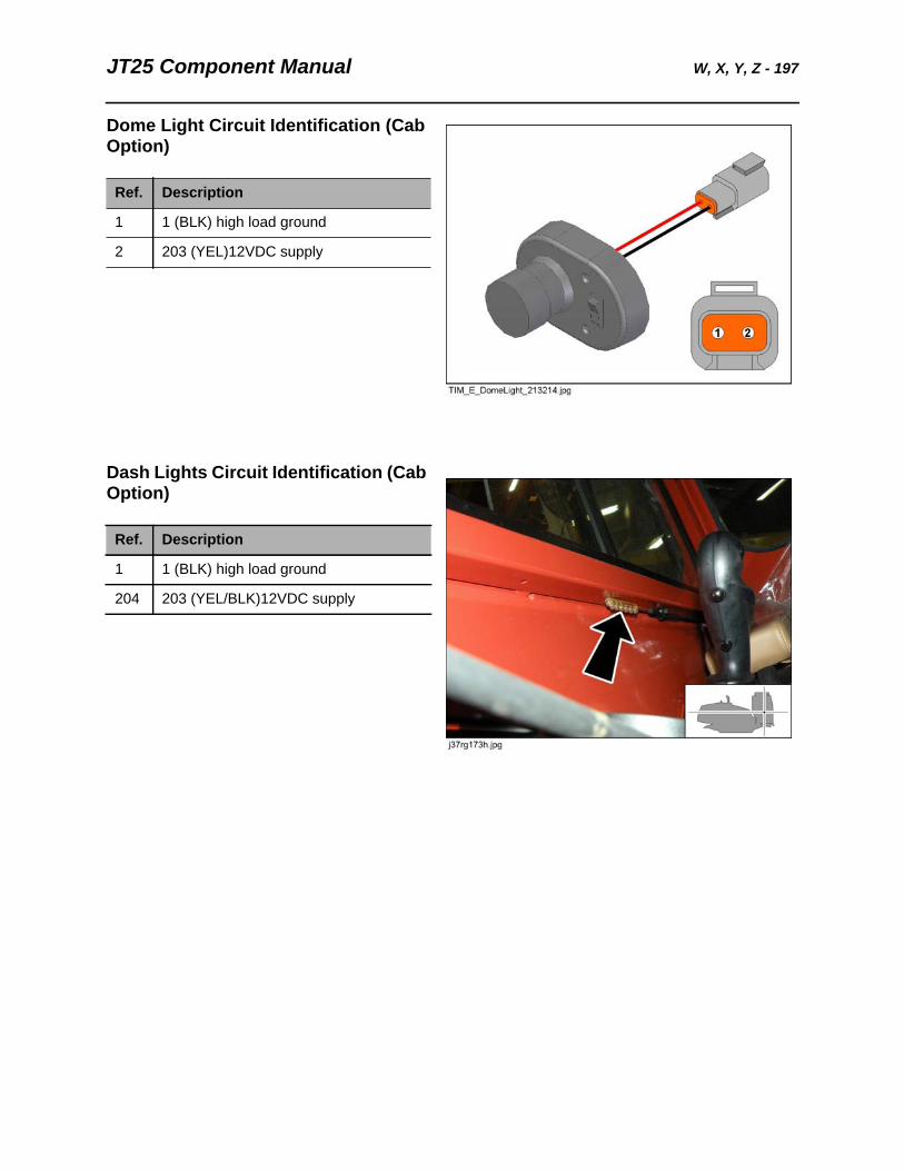
JT25 Component Manual W, X, Y, Z - 197
Dome Light Circuit Identification (Cab Option)
Dash Lights Circuit Identification (Cab Option)
Ref. Description
1 1 (BLK) high load ground
2 203 (YEL)12VDC supply
Ref. Description
1 1 (BLK) high load ground
204 203 (YEL/BLK)12VDC supply
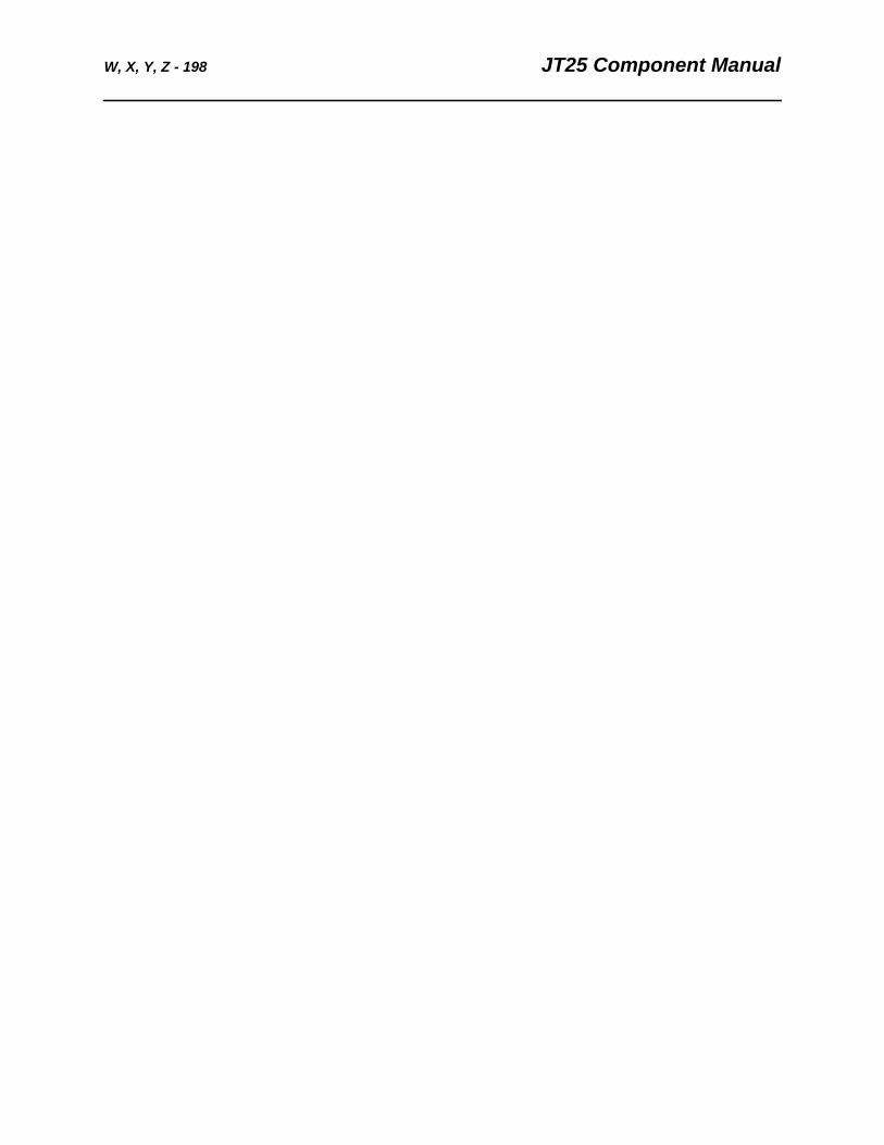
W, X, Y, Z - 198 JT25 Component Manual