component identification 23 - primus · unitronics industrial automation systems 1 ex-a1 i/o...
TRANSCRIPT

Unitronics Industrial Automation Systems 1
EX-A1 I/O Expansion Module Adapter
The EX-A1 interfaces between a variety of I/O expansion modules and specific Unitronics’ OPLCs.
A single adapter can be connected to up to 8 expansion modules.
The EX-A1 may either be snap-mounted on a DIN rail, or screw-mounted onto a mounting plate.
Component identification 1 Status indicators 2 OPLC to EX-A1 connection port 3 Power supply connection points 4 EX-A1 to expansion module
connection port
2
1
2 3
4
User safety and equipment protection guidelines This document is intended to aid trained and competent personnel in the installation of this equipment as defined by the European directives for machinery, low voltage and EMC. Only a technician or engineer trained in the local and national electrical standards should perform tasks associated with the electrical wiring of this device.
Under no circumstances will Unitronics be liable or responsible for any consequential damage that may arise as a result of installation or use of this equipment, and is not responsible for problems resulting from improper or irresponsible use of this device.
All examples and diagrams shown in the manual are intended to aid understanding. They do not guarantee operation.
Unitronics accepts no responsibility for actual use of this product based on these examples. Only qualified service personnel should open this device or carry out repairs. Please dispose of this product in accordance with local and national standards and regulations.
Check the user program before running it. Do not attempt to use this device with voltage exceeding permissible levels. Install an external circuit breaker and take all appropriate safety measures against short-
circuiting in external wiring.
Failure to comply with appropriate safety guidelines can result in severe personal injury or property damage. Always exercise proper caution when working with electrical equipment.
EX-A1 I /O Expansion Module Adapter 12/01
2 Unitronics Industrial Automation Systems
Mounting the EX-A1 Mounting Considerations
Do not install in areas with: excessive or conductive dust, corrosive or flammable gas, moisture or rain, excessive heat, regular impact shocks or excessive vibration.
Provide proper ventilation by leaving a minimum space of 10mm between the top and bottom edges of the device and the enclosure walls.
Do not place in water or let water leak onto the unit. Do not allow debris to fall inside the unit during installation.
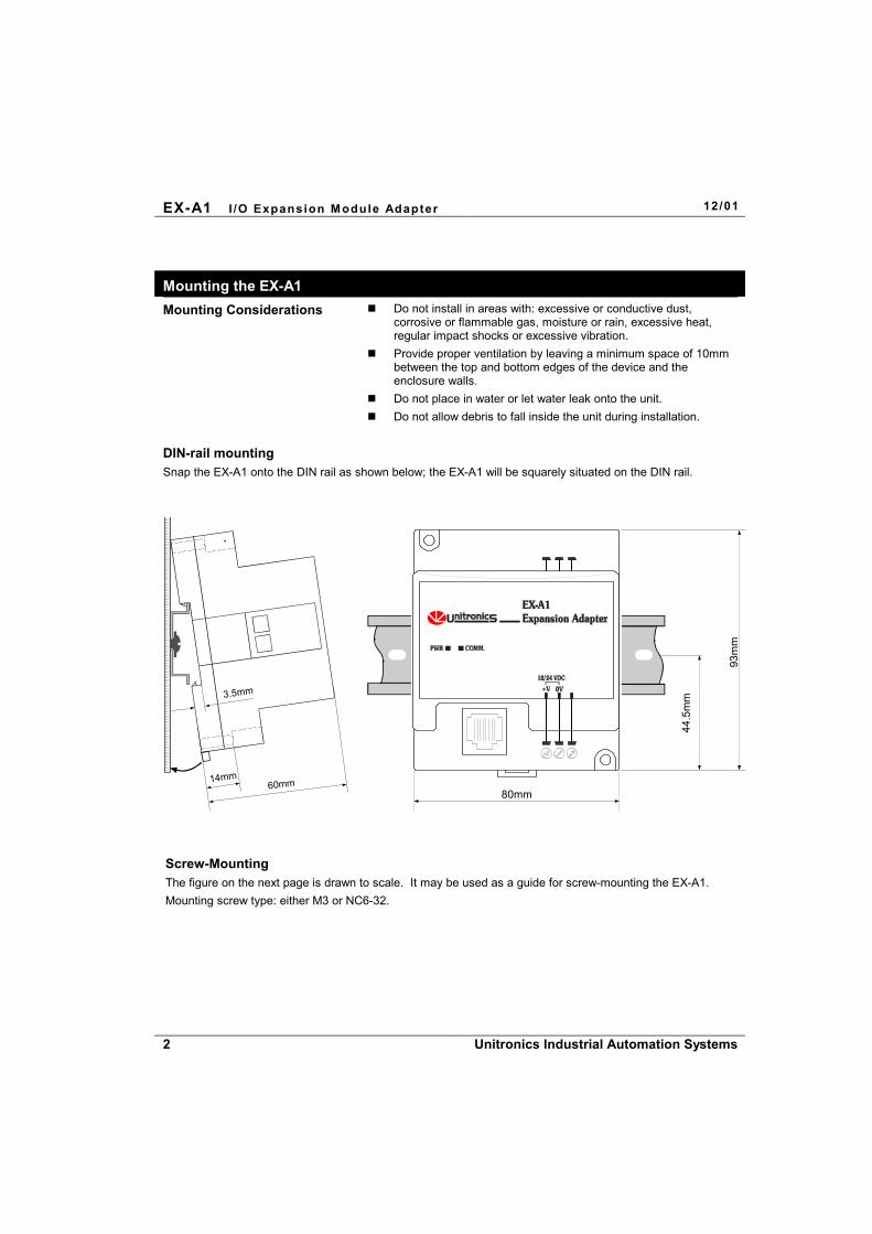
DIN-rail mounting Snap the EX-A1 onto the DIN rail as shown below; the EX-A1 will be squarely situated on the DIN rail.
60mm
3.5mm
14mm
80mm
93m
m
44.5
mm
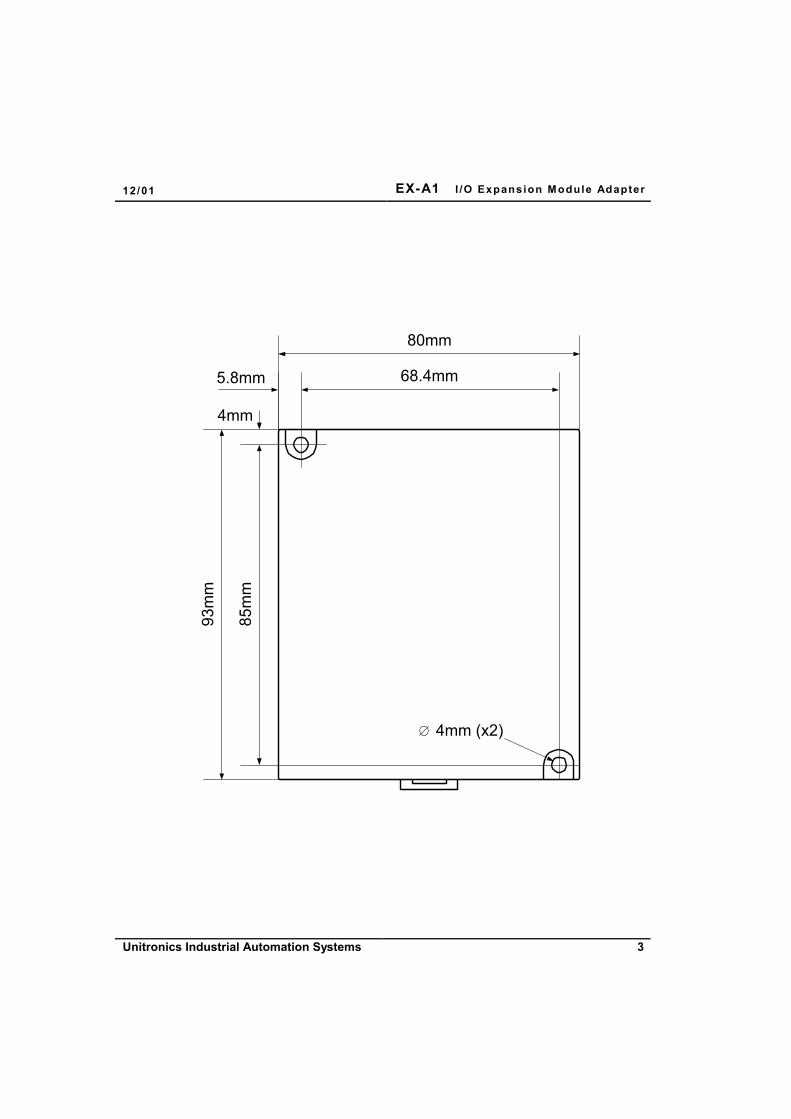
Screw-Mounting The figure on the next page is drawn to scale. It may be used as a guide for screw-mounting the EX-A1. Mounting screw type: either M3 or NC6-32.
12/01 EX-A1 I /O Expansion Module Adapter
Unitronics Industrial Automation Systems 3
4mm
5.8mm
85m
m
80mm
68.4mm
93m
m
4mm (x2)

EX-A1 I /O Expansion Module Adapter 12/01
4 Unitronics Industrial Automation Systems
Connecting the OPLC to the EX-A1
An OPLC, such as the M90 micro-OPLC, is connected to the EX-A1 adapter as shown below, via a category 5 shielded twisted pair cable (CAT 5, STP), terminated by RJ45 connectors. The cable provided with the EX-A1 is one meter long; cables of other lengths are available by separate order. Note that the cable must be earthed on the M90 side, via the yellow-green wire. To avoid damaging the system, do not connect or disconnect the device when the power is on.
I/Oexpansionport
Earth
M90 EX-A1
Shielded RJ45 connector pin-out Cable description
Pin #1
RJ-45 pin #
81
2436
D +D -
CK-CK+0V0V
signal
RJ-45 RJ-45
18
24
Connect to earth near the M90
18
24
12/01 EX-A1 I /O Expansion Module Adapter
Unitronics Industrial Automation Systems 5
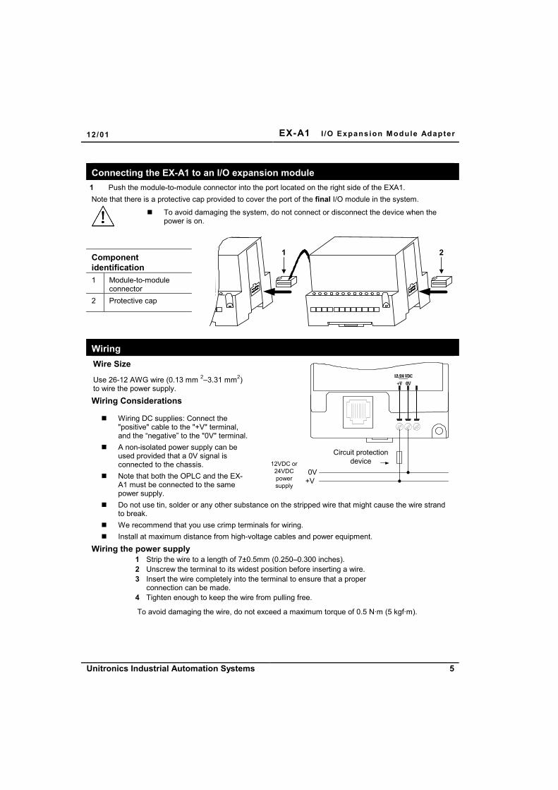
Connecting the EX-A1 to an I/O expansion module 1 Push the module-to-module connector into the port located on the right side of the EXA1. Note that there is a protective cap provided to cover the port of the final I/O module in the system.
To avoid damaging the system, do not connect or disconnect the device when the
power is on.
Component identification 1 Module-to-module
connector 2 Protective cap
1 2
Wiring Wire Size
Use 26-12 AWG wire (0.13 mm 2–3.31 mm2) to wire the power supply. Wiring Considerations
Wiring DC supplies: Connect the "positive" cable to the "+V" terminal, and the “negative” to the "0V" terminal.
A non-isolated power supply can be used provided that a 0V signal is connected to the chassis.
Note that both the OPLC and the EX-A1 must be connected to the same power supply.
Circuit protectiondevice
0V+V
12VDC or24VDCpowersupply
Do not use tin, solder or any other substance on the stripped wire that might cause the wire strand to break.
We recommend that you use crimp terminals for wiring. Install at maximum distance from high-voltage cables and power equipment.
Wiring the power supply 1 Strip the wire to a length of 7±0.5mm (0.250–0.300 inches).
2 Unscrew the terminal to its widest position before inserting a wire. 3 Insert the wire completely into the terminal to ensure that a proper
connection can be made. 4 Tighten enough to keep the wire from pulling free.
To avoid damaging the wire, do not exceed a maximum torque of 0.5 N·m (5 kgf·m).

EX-A1 I /O Expansion Module Adapter 12/01
6 Unitronics Industrial Automation Systems
Do not touch live wires. Do not connect the ‘Neutral or ‘Line’ signal of the 110/220VAC to the device’s 0V pin. In the event of voltage fluctuations or non-conformity to voltage power supply
specifications, connect the device to a regulated power supply. Double-check all the wiring before turning on the power supply.
EX-A1 Technical Specifications I/O module capacity Up to 8 I/O modules can be connected to a single adapter.
Power supply 12VDC or 24VDC (see Notes 1&2)
Permissible range 10.2 to 28.8VDC
Max. current consumption 650mA @ 12VDC; 350mA @ 24VDC
Typical power consumption 4W
Current supply for I/O modules
1A max. from 5V (see Note 3)
Galvanic isolation None
Status indicators LEDs
PWR Green indicator, lit when power is supplied.
COMM. Green indicator, lit when communication is established.
Environmental IP20/NEMA1
Operating temperature 0° to 50° C (32 to 122°F)
Storage temperature -20° to 60° C (-4 to 140°F)
Relative Humidity (RH) 5% to 95% (non-condensing)
Dimensions (WxHxD) 80mm x 93mm x 60mm (3.15” x 3.66” x 2.362”)
Weight 125g (4.3oz.)
Mounting Either onto a 35mm DIN-rail or screw- mounted.
Notes: 1 Both the OPLC and the EX-A1 must be connected to the same power supply. The EX-A1 and the OPLC must be turned on and off simultaneously.
2 The 12VDC power supply is supported by versions V2.00 and later.
3 Example: 2 I/O-DI8-TO8 units consume a maximum of 140mA of the 5VDC supplied by the EX-A1.
Accessories EX1-CA050 0.5 meter communication cable EX1-CA100* 1 meter communication cable EX1-CA200 2 meter communication cable EX1-CA400 4 meter communication cable IO-CAP Protective cap, used to cover the connection port of the final I/O module in the system
*EX1-CA100 is provided with the EX-A1 adapter; other cables are available by separate order.
12/01 EX-A1 I /O Expansion Module Adapter
Unitronics Industrial Automation Systems 7
Addressing I/Os on M90 Expansion Modules
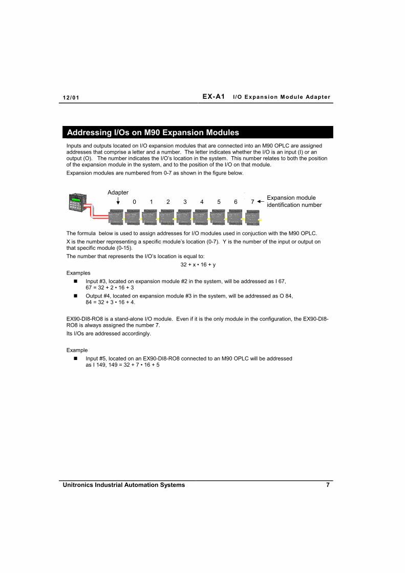
Inputs and outputs located on I/O expansion modules that are connected into an M90 OPLC are assigned addresses that comprise a letter and a number. The letter indicates whether the I/O is an input (I) or an output (O). The number indicates the I/O’s location in the system. This number relates to both the position of the expansion module in the system, and to the position of the I/O on that module. Expansion modules are numbered from 0-7 as shown in the figure below.
0 1 2 3 4 5 6 7Expansion moduleidentification number
Adapter
The formula below is used to assign addresses for I/O modules used in conjuction with the M90 OPLC. X is the number representing a specific module’s location (0-7). Y is the number of the input or output on that specific module (0-15). The number that represents the I/O’s location is equal to:
32 + x • 16 + y Examples
Input #3, located on expansion module #2 in the system, will be addressed as I 67, 67 = 32 + 2 • 16 + 3
Output #4, located on expansion module #3 in the system, will be addressed as O 84, 84 = 32 + 3 • 16 + 4.
EX90-DI8-RO8 is a stand-alone I/O module. Even if it is the only module in the configuration, the EX90-DI8-RO8 is always assigned the number 7. Its I/Os are addressed accordingly. Example
Input #5, located on an EX90-DI8-RO8 connected to an M90 OPLC will be addressed as I 149, 149 = 32 + 7 • 16 + 5

EX-A1 I /O Expansion Module Adapter 12/01
8 Unitronics Industrial Automation Systems