component based modeling and validation of a steering
TRANSCRIPT

Component based modeling and validation of a steeringsystem for a commercial vehicleCitation for published version (APA):Loof, J., Besselink, I. J. M., & Nijmeijer, H. (2016). Component based modeling and validation of a steeringsystem for a commercial vehicle. In M. Rosenberger, M. Plöchl, K. Six, & J. Edelmann (Eds.), The Dynamics ofVehicles on Roads and Tracks: Proceedings of the 24th Symposium of the International Association for VehicleSystem Dynamics (IAVSD 2015), Graz, Austria, 17-21 August 2015 (pp. 15-24). CRC Press.https://doi.org/10.1201/b21185-4
DOI:10.1201/b21185-4
Document status and date:Published: 01/01/2016
Document Version:Accepted manuscript including changes made at the peer-review stage
Please check the document version of this publication:
• A submitted manuscript is the version of the article upon submission and before peer-review. There can beimportant differences between the submitted version and the official published version of record. Peopleinterested in the research are advised to contact the author for the final version of the publication, or visit theDOI to the publisher's website.• The final author version and the galley proof are versions of the publication after peer review.• The final published version features the final layout of the paper including the volume, issue and pagenumbers.Link to publication
General rightsCopyright and moral rights for the publications made accessible in the public portal are retained by the authors and/or other copyright ownersand it is a condition of accessing publications that users recognise and abide by the legal requirements associated with these rights.
• Users may download and print one copy of any publication from the public portal for the purpose of private study or research. • You may not further distribute the material or use it for any profit-making activity or commercial gain • You may freely distribute the URL identifying the publication in the public portal.
If the publication is distributed under the terms of Article 25fa of the Dutch Copyright Act, indicated by the “Taverne” license above, pleasefollow below link for the End User Agreement:www.tue.nl/taverne
Take down policyIf you believe that this document breaches copyright please contact us at:[email protected] details and we will investigate your claim.
Download date: 06. Dec. 2021

COMPONENT BASED MODELING AND VALIDATION OF ASTEERING SYSTEM FOR A COMMERCIAL VEHICLE
Jan Loof, Igo Besselink, Henk NijmeijerDynamics and Control Group, Department of Mechanical Engineering, Eindhoven University ofTechnology, Den Dolech 2, 5600 MB Eindhoven, The Netherlands. E-mail address of lead author:[email protected]
ABSTRACT: The prediction of steering wheel torque in a truck is a challenging subject due tothe many components connecting the driver to the front wheels. In order to accurately predict thesteering wheel torque a highly detailed model is required. Steering systems in commercial vehiclehandling simulation models found in literature are often modeled in a simple way while litera-ture on passenger vehicles suggests the necessity of a higher model complexity. In this research ahighly detailed model with four states, friction, stiffness, hydraulic assistance and the necessarykinematic relations is developed. This model could assist in the development of the steering sys-tem in the early stages of the design. The model is able to accurately predict the steering wheeltorque, drag link force and king pin angles. The parameters for this model are estimated by meansof dedicated tests and the steering system model is validated outside of the vehicle.
Keywords: Vehicle steering system, Hydraulic power-steering, Commercial vehicle, Steeringsystem model
1 INTRODUCTION
In 2010 the 1 billion unit mark of vehicles in operation worldwide was surpassed. Only in Europea total of 35 million heavy-duty trucks are registered, this amount is expected to grow by 17percent in 2030. In other parts of the world this growth is expected to be the strongest in Asiaand and the Middle East (ICCT 2013). Trucks and in particular tractor-semitrailers are overrep-resented in accident statistics. This is caused by the unique risk factors in truck driving, such aspoor rear and side visibility, leading to blind spot crashes (Schoon et al. 2008, SWOV 2009). Sec-ondly, on longer trips, truck drivers are vulnerable to fatigue and highway hypnosis, contributingto loss-of-control accidents and road departures (Summala & Mikkola 1994). Finally the complexdynamics and growing sizes of trucks (Besselink et. all 2015) make them prone to accidents.
First steps in improving safety have been taken, such as anti-lock braking system and elec-tronic stability control, which are now both standard by regulations in new trucks. State of the artdriver assistance systems include: adaptive cruise control, intelligent speed adaptation, forwardcollision warning, automatic emergency braking, blind spot information, lane departure warningand curve-speed warning. Some of these systems are applied in high-end trucks, however, mostare still under active development. This development leads to the future prospect to have fullyautomated trucks on highways, where the truck operator is no longer a driver but a supervisor.
In order to facilitate features such as automated steering, an active steering system is required.For this, deeper knowledge of a conventional truck steering system is required such that the opti-mal position of an extra actuator can be determined. A particular challenge in the design of atruck steering system is on center steering feel. In general, commercial vehicles make use of ahydraulic system which amplifies the input torque of the driver with the so called boost-curve, seeFigure 1(a). The application of hydraulic assistance based on torque input can result in an indirect

steering feel, especially around the center-position due to the zero gradient of the boost-curve atthis position (Pfeffer et. all 2008).
Tin
Tout
(a) Example of a boost-curve (b) Typical steering system (Bennet 2005)
Figure 1.
Steering systems in truck handling simulation models found in literature are often modeled ina simple way. In many cases they do not incorporate steering compliance or power-steering (Loth1996) and if they do, inertias of the system components are often not considered (Govindan 2012).
Literature on steering system models in passenger cars reveals that in most cases the steeringsystem is modeled in a relative simple manner. Most models have three degrees of freedom with astiffness between the steering wheel and the assistance motor and a stiffness between the wheelsand the assistance motor (Parmar and Hung 2004, Song et. all 2004). However, if we want topredict the steering wheel torque in an accurate way, a more detailed model is required. In (Loziaand Zardecki 2007) it is shown that a coulomb friction model is sufficient to describe the steer-ing wheel torque during cornering. (Pfeffer et. all 2008) also shows that modeling of friction isrequired to predict the steering wheel torque around the center position. (Rosth 2007) shows aconcept with an additional motor on the input side of the steering house to compensate for frictionin the steering system and enable features like parking pilot, lane keeping assist, emergency laneassist, active yaw control and torque reference control.
Figure 1(b) shows a typical steering system layout in a commercial vehicle. From this figure itbecomes apparent that the steering system contains a lot of components connecting the steeringwheel to the front wheels due to a sprung cabin and limited space around the engine. This resultsin multiple universal joints, a hydraulic power-steering system and multiple transitions from rota-tion to translation and vice versa. The ratio of input torque of the driver and output torque atthe front wheels is much bigger compared to a passenger vehicle and therefore low amounts offriction on the driver side can influence the on center steering feel significantly. In this research ahighly detailed model is developed which takes all of these aspects into account.
The goals of this paper are defined as follows:
• Predict the steering wheel torque in the on center region as well as for larger steering wheelangles.
• Have a component based structure so it can be used to analyze the design of such a system.
First the steering system model and parameter estimation will be discussed in section 2.Section 3 shows the validation of this model outside of the vehicle. The conclusions and rec-ommendations are presented in section 4.

2 STEERING SYSTEM MODEL AND PARAMETER IDENTIFICATION
Steering systems in commercial vehicles consist of many parts in between the driver and thewheels as can be seen in Figure 1(b). The driver actuates the steering wheel which is connectedto the steering column. The steering column is connected to the steering shaft by means of auniversal joint. This steering shaft is connected to the input side of the steering house via a seconduniversal joint. Inside this steering house, see Figure 3(b), a torsion bar is present which is usedto estimate the driver torque. This torsion bar operates a set of hydraulic valves which regulatethe pressure to a hydraulic cylinder. The torsion bar is also connected to the hydraulic piston viaa spindle which converts rotation into translation. This hydraulic piston is connected to a sectorshaft where the translation is converted into a rotation again. This is the output of the steeringhouse. The output of the steering house is connected to the pitman arm which is connected to thesteering arm via the drag link. Via this steering arm the translation of the drag link is converted toa rotation around the king pin axis. The steered wheel is connected to the other wheel by meansof a tie rod.
2.1 Overview
In order to understand the steering system design and to investigate a suitable position for an extraactuator, a model is required. This model should be able to accurately describe the steering wheeltorque felt by the driver as well as the torque at the output side. A model with four degrees offreedom is used in order to implement friction at four locations. In between the masses, springshave been used to model the flexibility and a gear-ratio is implemented. The assistance torque isgenerated as a function of the input torque. The steering system model is shown in Figure 2 wherethe same structure as in Figure 1(b) is used. The equations of motion for the system read:
Jswδsw = Tsw − Tfric,sw − (δswiuj − δsh,in)ksciuj − Tecc,sw (1)
Jsh,inδsh,in = (δswiuj − δsh,in)ksc − (δsh,in − δsh,outish)khua − Tfric,hua (2)
Jsh,outδsh,out = (δsh,in − δsh,outish)khua + TPS − (δsh,out − δkpipa)kha − Tfric,ha (3)
Jkpδkp = (δsh,out − δkpipa)khaipa − Tfric,kp − Tkp (4)
ksc
Jsw, δsw
Tsw
Tfric,sw
Tfric,hua
ktb kspindle kha
δsh,out
∆tb
kcent
∆cent
Jsh,out
Tfric,ha
-
TPS
Boost curve
Jkp, δkp
Tkp.
ipa
Tfric,kp
U-joint 1
U-joint 2
Jsh,in, δsh,in
Hydraulically Un-Actuated (hua) Hydraulically Actuated (ha)
Steering-wheel
King-pin
ish
Figure 2. Steering system model
2.2 Hydraulically Un-Actuated part
The interaction with the driver happens at the steering wheel, where a torque is applied by thedriver, Tsw. This torque is applied on the steering wheel inertia, Jsw, and results in a steeringwheel angle, δsw. The steering wheel inertia shows a coulomb friction torque Tfric,sw which istypical for bearings and universal joints. In order to implement the friction in the model a resetintegrator model has been used (Haessign & Friedland 1991) due to its straight-forward imple-mentation and computational performance. Since bearings in general do not only show coulombfriction but a viscous damping component as well this is added in the form of dsw.

g
msw
δsw
(a) Steering wheel eccentricity (b) Typical inside of a steering house
Figure 3.
In a typical truck, height adjustment of the steering wheel is possible. In order to facilitate thisheight adjustment and because of packaging reasons, universal joints (U-joints) are used. Thekinematic relations of a universal joint with input angle δUjoint,in, output angle δjoint,out, torqueinput TUjoint,in, torque output TUjoint,out and inclination angle β are defined as:
δUjoint,out = arctan
(tan(δUjoint,in)
cos(β)
)(5)
TUjoint,out = TUjoint,in1− sin(β)2 cos(δUjoint,in)2
cos(β)(6)
In this model, two U-joints are used with inclination angles β1 and β2. For the sake of readabil-ity the full kinematic relations for the series connection of these U-joints are not given here. Wedefine a ratio iuj(δsw, β1, β2) which defines the ratio caused by the two U-joints in series. Thisvariable ratio is depending on the input angle δsw and angles β1 and β2.
The steering wheel center of gravity does not necessarily coincide with the rotation axis asshown in Figure 3(a). The shortest distance between the center of gravity and the rotation axis isindicated with Lecc,sw. If the steering wheel has an angle θsw with the horizontal plane and massmsw a torque will be generated as a function of the steering wheel angle:
Tecc,sw = mswLecc,sw sin(θsw) sin(δsw) (7)
The stiffness in between the steering wheel and the input of the steering house is lumped intoone parameter, ksc. This stiffness connects to the input of the steering house which has inertiaJsh,in and angle δsh,in. A friction torque is present on the input, Tfric,hua, where hua standsfor Hydraulically Un-Actuated with viscous damping dhua. This friction is again caused by thebearings used for the torsion bar and the spindle.
The internals of the input side of the steering house is represented by a series of springs:
1. a spring with stiffness kcent, used to create a lower on center stiffness.2. the torsion bar stiffness ktb, also used to determine the amount of assistance torque.3. the stiffness of the spindle kspindle, connects the torsion bar to the piston.
In order to have a lower on center stiffness engaging only in the on center region, a free play∆cent is placed in parallel. In this way, the total stiffness will only be lower if the torque onthis spring is within ±∆centkcent. The same strategy is used for the torsion bar by means of freeplay ∆tb. A total stiffness khua is defined as the resulting stiffness of these springs. Given theassumption that ktb∆tb > kcent∆cent, three possibilities for khua can be defined:
khua1 = kspindle (8)
khua2 =(k−1tb + k−1
spindle
)−1(9)
khua3 =(k−1cent + k−1
tb + k−1spindle
)−1(10)
The value of khua is based upon the torque level in the series of springs:
khua =
khua1, if |δsh,in − δsh,outish| ≥ ∆centkcent
khua3+ ∆tbktb
khua2
khua2, if |δsh,in − δsh,outish| ≥ ∆centkcent
khua3
khua3, otherwise
(11)
2.3 Hydraulically Actuated part
This stiffness is connected to the output inertia of the steering house Jsh,out, which is the lumpedinertia of the spindle, equivalent piston and sector shaft, via the ratio ish:
ish =Rpa
Lspindle(12)
where Lspindle is the lead of the spindle which connects the input of steering house to thehydraulic piston and Rpa is the radius of the sector shaft connecting the hydraulic piston to theoutput shaft of the steering house as shown in Figure 3(b).
The seals in the hydraulic cylinder cause a friction force which is translated to a friction torquewith magnitude Tfric,ha where ha stands for Hydraulically Actuated. Since the hydraulic systemalso functions as a damper for the system (oil is squeezed through narrow channels upon move-ment of the piston), the assumption is made that the piston acts as a damper with coefficient dha.The output is connected to the king pin axis by means of the spring kha, this spring represents thelumped stiffness of all components in between the steering house and the king pin axis. A ratioipa is defined, which is the kinematic ratio between the pitman arm and drag link.
The inertia of the wheels, hubs and tie-rod is lumped into one parameter, Jkp, with angle δkp.This inertia shows a static friction torque Tfric,kp and a viscous damping dkp caused by the needlebearings which support the king pin axis. The wheels produce a torque with magnitude Tkp causedby the tyres and the king pin orientation (Bakker 2012).
Power-steering torque is generated as a result of the torque acting on the torsion bar. Torsionbar torque is defined as:
Ttb = (δsh,in − δsh,outish)khua with |Ttb| ≤ ktb∆tb (13)
An empirical approach to relate the assistive torque to the torsion bar torque is used. The boostcurve that models this is describe by parameters a, b, c and d:
Tps = sign(Ttb)(a(eb|Ttb| − 1) + c(ed|Ttb| − 1)
)(14)
This definition ensures predictable behavior outside the fitting range, zero power-steeringtorque at zero torsion bar torque and symmetrical behavior for positive and negative torque.
2.4 Parameter identification
The model contains a total of 30 parameters, some of these parameters can be found by specifi-cations of the manufacturer, others require additional testing. A total of four additional tests havebeen performed:

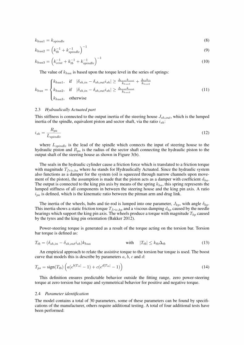
1. The piston of the steering system is blocked in order to assess the properties of the hua part,see Figure 4(a). In this way the stiffness of the spindle and torsion bar, respectively kspindle andktb, are identified by means of a least squares fit with a second order model. Also the parallelfree play element ∆tb can be identified. An example of the outcome of such a measurement isshown in Figure 5(a) where the change in stiffness is seen.
2. The output of the steering system is blocked by fixating the drag link to the world, see Figure4(b). This experiment is done without power-steering in order to identify the stiffness of the hapart, kha. An example of this test is shown in Figure 5(b). This figure also shows the reducedstiffness around the center position kcent as well as the parallel free play ∆cent.
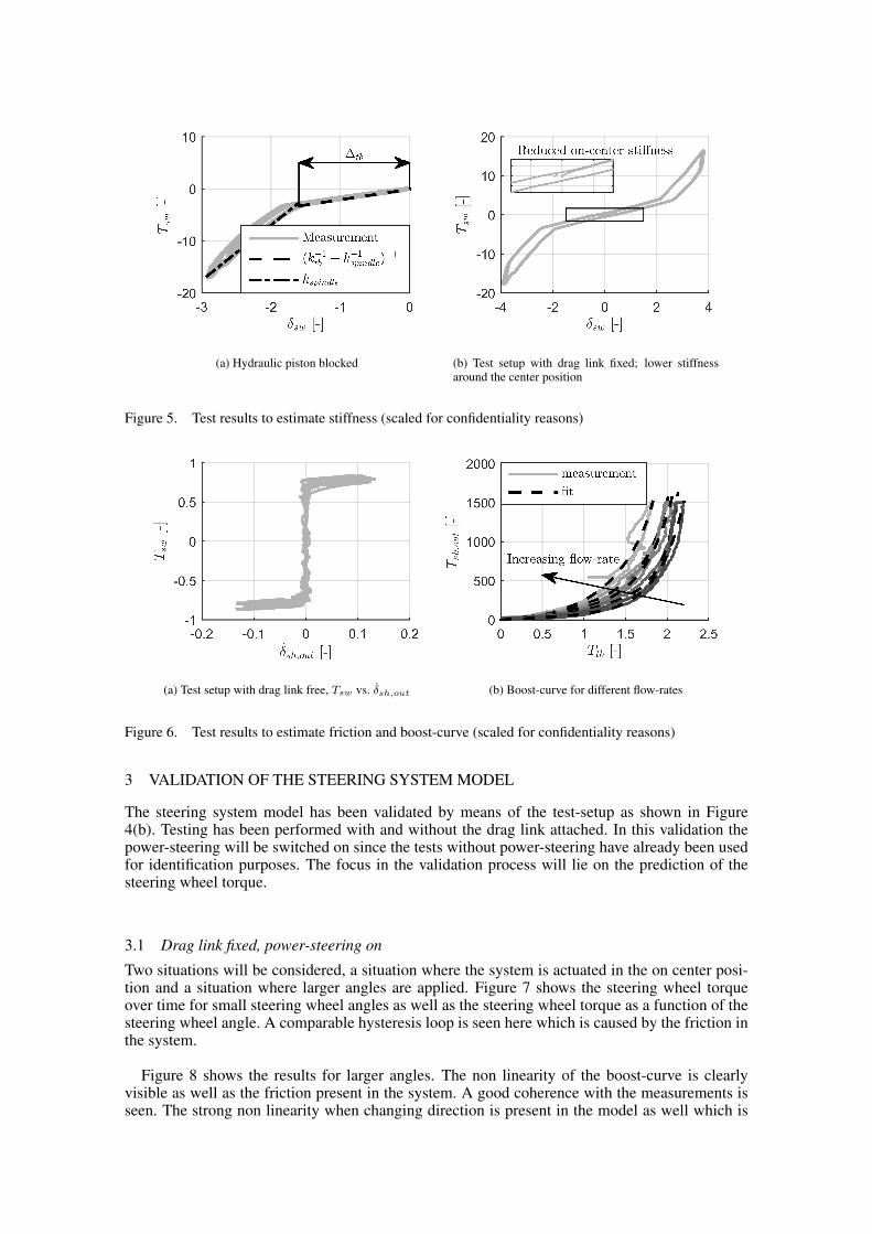
3. The output of the steering system is free, experiments are done without power-steering toidentify the friction elements Tfric,hua and Tfric,ha. This test can also be used to check theratio ish. Figure 6(a) shows an example of the friction identification on the output side of thesteering house. The coulomb friction on the piston Tfric,ha is clearly visible.
4. The output of the steering system is blocked by fixating the output shaft to a force sensor andswitching the power-steering on. The input and output torques are measured as well as theinput angle. This test is used to identify the coefficients a, b, c and d used in the power-steeringmodel. Figure 6(b) shows the measured boost-curves together with the fits for different flow-rates. In order to estimate the torque acting on the torsion bar a compensation for the frictionon the input Tfric,hua is done before fitting.
Since all measurements have been executed at low velocities, limited information regardingthe damping is present. Since the steering system manual describes a damping effect of shockforces from the steered wheels and no oscillations have been seen during the measurements, theassumption is made that the hydraulic piston is critically damped, thus ζha = 1. In this waykickback at the steering wheel is prevented. The other damping parameters have been chosen at5 % thus ζsw = ζhua = ζkp = 0.05 in order to prevent high frequency oscillations which areoutside the scope of this research. This results in the following damping coefficients:
dsw = 2ζsw√Jswksc (15)
dhua = 2ζhua
√Jsh,in(ksc + khua) (16)
dha = 2ζha
√Jsh,out(khuai
2sh + kha) (17)
dkp = 2ζkp
√Jkpkhai2pa (18)
(a) Hydraulic piston blocked
δsw, Tsw δsh,out
Fdl
(b) Drag link fixed
Figure 4.
(a) Hydraulic piston blocked (b) Test setup with drag link fixed; lower stiffnessaround the center position
Figure 5. Test results to estimate stiffness (scaled for confidentiality reasons)
(a) Test setup with drag link free, Tsw vs. δsh,out (b) Boost-curve for different flow-rates
Figure 6. Test results to estimate friction and boost-curve (scaled for confidentiality reasons)
3 VALIDATION OF THE STEERING SYSTEM MODEL
The steering system model has been validated by means of the test-setup as shown in Figure4(b). Testing has been performed with and without the drag link attached. In this validation thepower-steering will be switched on since the tests without power-steering have already been usedfor identification purposes. The focus in the validation process will lie on the prediction of thesteering wheel torque.
3.1 Drag link fixed, power-steering on
Two situations will be considered, a situation where the system is actuated in the on center posi-tion and a situation where larger angles are applied. Figure 7 shows the steering wheel torqueover time for small steering wheel angles as well as the steering wheel torque as a function of thesteering wheel angle. A comparable hysteresis loop is seen here which is caused by the friction inthe system.
Figure 8 shows the results for larger angles. The non linearity of the boost-curve is clearlyvisible as well as the friction present in the system. A good coherence with the measurements isseen. The strong non linearity when changing direction is present in the model as well which is

(a) Steering wheel torque as function of time (b) Steering wheel torque as function of steeringwheel angle
Figure 7. Validation in the center region with a fixed drag link (scaled for confidentiality reasons)
(a) Steering wheel torque as function of time (b) Steering wheel torque as function of steeringwheel angle
Figure 8. Validation for larger angles with a fixed drag link (scaled for confidentiality reasons)
crucial for steering feel.
3.2 Drag link free, power-steering on
Again the on center situation and the large angle position will be analyzed. Figure 9 shows theresults for small angles (on center behavior). The coherence with the measurements is clear butnot as good as with the drag link fixed. Some a-symmetry in the measurements is seen which isnot present in the model.
Figure 9 shows the response for larger angles. A position dependent friction appears to bepresent. This is also implemented in the model by means of a look-up table. The cause of this is inthe design of the steering house, the free play is minimized in the center position which increasesthe friction in the system around the center position.

(a) Steering wheel torque as function of time (b) Steering wheel torque as function of steeringwheel angle
Figure 9. Validation in the center region with a free drag link (scaled for confidentiality reasons)
(a) Steering wheel torque as function of time (b) Steering wheel torque as function of steeringwheel angle
Figure 10. Validation for larger angles with a free drag link (scaled for confidentiality reasons)
4 CONCLUSIONS AND RECOMMENDATIONS
A steering system model has been developed which includes the inertias, friction and flexibilityof components. The eccentric properties of the steering wheel as well as the universal joints havebeen modeled. An empirical approach has been used to model the assistance torque delivered bythe hydraulic system.
The parameters for this model have been estimated by four dedicated tests. One test consistsout of blocking of the hydraulic piston to estimate the stiffness on the driver-side of the steeringhouse. In the second test the output of the steering house is freed an the friction in the system isdetermined. In the third test the drag link is fixed to a force sensor and the total stiffness of thesteering house is found. In the fourth test the output of the steering house is fixed to a force sensorand the power-steering is switched on. This is used to find the parameters for the boost-curvemodel.
The model has been validated using measurements for steady-state conditions by means of twotests, one with the drag link free and one with the drag link fixed. The power-steering is switchedon and different quantities such as steering wheel torque, pitman arm angle and drag link force aremeasured. The model uses the steering wheel angle and the boundary conditions as an input and

the response is compared with the measurements. The steering wheel torque, pitman arm angleand drag link force can be predicted accurately.
In order to improve the steering system model, the hydraulic model can be improved. This canbe done by extending the test-setup with pressure sensors inside the steering house. By measuringthe pressure directly the pressure dependent friction as well as the valve characteristic can befound. The test-stand can also be improved by mounting a spring instead of a fixed drag link suchthat the operating condition is comparable to the situation in the vehicle. This spring should havea stiffness comparable to the combined stiffness of the two front tyres in the situation where thevehicle is running straight ahead at high-way speed.
Future work will consist out of improvement of the hydraulic model and implementation in amulti-body vehicle model. Validation will be done by a series of full vehicle tests with an instru-mented steering system. Furthermore the possibility of autonomous steering via placement of anextra actuator in the steering system will be investigated with help of this model.
5 ACKNOWLEDGMENTS
This research was supported by the Stichting voor de Technische Wetenschappen (Dutch Tech-nology Foundation) STW.
REFERENCES
Bakker, P.M. & 2012. Straight line steering moment analysis of a commercial vehicle, Eindhoven Universityof Technology, Eindhoven, Masters Thesis.
Bennett, S. 2005. Heavy Duty Truck Systems. New-York: Cengage Learning.Besselink, I.J.M. & Pauwelussen, J. & Kraaijenhagen, B. 2015. Greening and Safety Assurances of Future
Modular Road Vehicles, Eindhoven University of Technology, Eindhoven & HAN University of AppliedSciences, Arnhem & MAN Truck and BUS A.G., Munch. VDI Commercial vehicles 13th InternationalConference.
Govindan, V. 2012 Simulation study on truck wandering during straight line driving, Eindhoven Universityof Technology, Masters thesis.
Haessign, David A. & Friedland, B. 1991. On the modeling and simulation of friction. Journal of DynamicSystems, Measurement, and Control, volume 113: pages 354-362.
Lozia, Z. & Zardecki, D. 2007. Friction and Stick-Slip Phenomena in Steering System Modeling andSimulation Studies. Steering & Suspension Technology Symposium
Loth, S. 1996. Fahrdynamische Einflussgroessen beim Geradeauslauf von PKW., TU Carolo Wilhelmina,Braunschweig. PhD thesis
Parmar, M. & Hung, Y.J. 2004. A Sensorless Optimal Control System for an Automotive Electric PowerAssist Steering System. IEEE Transactions on industrial electronics, volume 51, no. 2, pages 290 - 298.
Pfeffer, P.E. & Harrer, M. & Johnston, D.N. 2008. Interaction of vehicle and steering system regarding oncentre handling, Vehicle System Dynamics, volume 46, issue 5, pages 413-428.
Rosth, M. 2007. Hydraulic Power Steering System Design in Road Vehicles, Analysis, Testing andEnhanced Functionality., Linkoping Studies in Science and Technology, PhD thesis.
Schoon, C.C. & Doumen, M.J.A. & De Bruin, D. 2008. De toedracht van dodehoekongevallen en maatrege-len voor de korte en lange termijn. Retreived from: http://www.swov.nl/rapport/r-2008-11a.pdf
Song, J. & Boo, K. & Seob Kim, & H. Lee, & J. Hong, S. 2004. Model development and control method-ology of a new electric power steering system. Journal of Automobile Engineering volume 218, no. 9,pages 967-975.
Summala, H. & Mikkola, T. 1994. Fatal accidents among car and truck drivers: Effects of fatigue, age, andalcohol consumption., Human Factors, volume 36 pages 315-326
SWOV Institute for Road Safety Research 2009. SWOV Fact sheet. Blind spot crashes., Retrieved fromhttp://www.swov.nl/rapport/Factsheets/UK/FS_Blind_spot_crashes.pdf
The International Council on Clean Transportation 2013. European vehicle market statistics, pocketbook2013, Retreived from http://www.theicct.org/sites/default/files/publications/EU_vehiclemarket_pocketbook_2013_Web.pdf
TRW Automotive 2002. Steering Diagnostics Service Manual. Technical manual