compliance upgrade of the heating and cooling systems in
TRANSCRIPT

1
Directorate-General for Infrastructure and Logistics
Directorate C – Resources
L-2929 LUXEMBOURG
CONTRACTS AND PROCUREMENT UNIT
LUXEMBOURG
INVITATION TO TENDER No 06A40/2014/M021
Compliance upgrade of the heating and cooling systems in the EU House
building in Nicosia
4. TECHNICAL PROVISIONS AND SPECIFICATIONS

2
INVITATION TO TENDER No 06A40/2014/M021 ............................................................ 1 INTRODUCTION ..................................................................................................................... 4
1. OBJECT OF THE CONTRACT .......................................................................... 4
2. STANDARDS ........................................................................................................ 4
3. EQUIPMENT ......................................................................................................... 4 3.1. Pipes ....................................................................................................................... 5
4. ORGANISATION .................................................................................................. 6
4.1. Performance ....................................................................................................... 6 4.2. Ancillary services ........................................................................................... 6
4.3. Scheduling ........................................................................................................ 7 4.4. Warranty, maintenance and training.......................................................... 7
4.4.1. Warranty ............................................................................................................ 7 4.4.2. Maintenance ..................................................................................................... 7
4.4.3. Training .............................................................................................................. 7
TITLE 1 HEAT PUMPS ....................................................................................................... 9 1. GENERAL .............................................................................................................. 9
Position 1.1 ........................................................................................................................... 11
Position 1.2 ........................................................................................................................... 11
Position 1.3 ........................................................................................................................... 12
TITLE 2 AIR HANDLING UNITS (AHUs) ...................................................................... 13
1. GENERAL ............................................................................................................ 13
Position 2.1 ........................................................................................................................... 13
Position 2.2 ........................................................................................................................... 13
Position 2.3 ........................................................................................................................... 14 TITLE 3 COOLING PRODUCTION AND DISTRIBUTION UNITS FOR AHUs....... 15
1. GENERAL ............................................................................................................ 15 Position 3.1 ........................................................................................................................... 15
Position 3.2 ........................................................................................................................... 15 TITLE 4 AIR-CONDITIONING FOR THE IT ROOM ..................................................... 17
1. GENERAL ............................................................................................................ 17
Position 4.1 ........................................................................................................................... 18
Position 4.2 ........................................................................................................................... 18
TITLE 5 MISCELLANEOUS AIR-CONDITIONING INSTALLATIONS..................... 20
1. GENERAL ............................................................................................................ 20
Position 5.1 ........................................................................................................................... 20
Position 5.2 ........................................................................................................................... 20 Position 5.3 ........................................................................................................................... 20
TITLE 6 FAN COIL UNITS ............................................................................................... 22
1. GENERAL ............................................................................................................ 22
Position 6.1 ........................................................................................................................... 22 Position 6.2 ........................................................................................................................... 23
TITLE 7 ELECTRICITY ..................................................................................................... 24 1. GENERAL ............................................................................................................ 24
Position 7.1 ........................................................................................................................... 25
Position 7.2 ........................................................................................................................... 25
Position 7.3 ........................................................................................................................... 26
Position 7.4 ........................................................................................................................... 26 Position 7.5 ........................................................................................................................... 26
Position 7.6 ........................................................................................................................... 27

3
TITLE 8 MISCELLANEOUS............................................................................................. 28 Position 8.1 ........................................................................................................................... 28
Position 8.2 ........................................................................................................................... 28 Position 8.3 ........................................................................................................................... 28
Position 8.4 ........................................................................................................................... 28 TITLE 9 REPLACING THE INDOOR UNITS ................................................................ 29
1. GENERAL ............................................................................................................ 29 Position 9.1 ........................................................................................................................... 29
Position 9.2 ........................................................................................................................... 29
ANNEX I: CURRENT STATUS OF INSTALLATIONS .................................................. 30 ANNEXE II: Specific Health & Safety Plan (SHSP) ..................................................... 35

4
INTRODUCTION
1. OBJECT OF THE CONTRACT
The European Parliament is arranging for the general upgrade of its heating and cooling systems, which shall be carried out by following the programme outlined below:
replacing the heat pumps (Dakin) located on the roof with a direct expansion system for the fan coil units;
replacing the heat pumps (Trane) located on the roof with a direct expansion system for the batteries of the air handling units;
replacing the air handling units;
replacing the four split air-conditioning units (transformer room, electrical/UPS room, lift plant room, storage room);
replacing the air-conditioning cabinet in the IT room, and its air-cooled exchanger located on the roof;
in addition, reviewing the current electrical power supply.
The European Parliament requires each apparatus/installation covered by this invitation to tender to have the features and specifications that are offered by the models cited as a reference, or by any other model that has equivalent features and specifications. The equivalence of the other models shall be determined in relation to the reference specifications. These reference specifications are reiterated below by way of example. All the makes cited in these specifications are also indicated to illustrate the reference specifications that will be used to verify the equivalence of alternative makes.
2. STANDARDS
The work involving the ventilation and air-conditioning installations shall be undertaken in accordance with the current standards in force, notably:
Regulation (EC) No 1005/2009 of the European Parliament and of the Council of 29 June 2000 on substances that deplete the ozone layer;
the circular prohibiting R22 refrigerant – Regulation (EC) No 2037/2000;
the current standards and regulations in force in Cyprus.
3. EQUIPMENT
The equipment to be used by the contractor shall be new. They must correspond to all required standards. All installed equipment shall immediately be protected from corrosion. All weld lines and scratches shall be painted over; this operation also applies to any pipes that are to be thermally insulated, and must be carried out before the thermal insulation layers are placed around them. All items of equipment requiring a certificate of approval shall come with one. These items of equipment shall only be used as prescribed, and shall be compatible with each other. The successful tenderer shall undertake to comply with the environmental legislation in force in the field of the contract. It should be noted in this connection that the European Parliament applies the EMAS environmental management system.
Should the tenderer opt to use an item of equipment that is not set out in the present specifications, it must:
1°) guarantee that the item of equipment is fully compatible with the fan coil units in place;

5
2°) provide the complete technical documentation for the item of equipment proposed, setting out its technical
specifications, which must be at least equivalent to those of the item of equipment listed in the present
specifications;
3°) undertake, if a different item of equipment is installed upon the tenderer’s recommendation and it then
transpires that this item of equipment is not compatible with the apparatus already in place, to replace the
installed item of equipment.
Since these new installations are to be connected to the existing pipework, the insulation protecting the pipes already in place shall need to be removed and disposed of. In its bid, the tenderer shall make allowances for the fact that it will be required to replace the insulation on all the pipes on the roof. This operation can only be carried out once it has been confirmed that the pipes are in good working order (visual inspections, pressure tests, leaktightness tests, etc. in accordance with generally recognised codes of practice). Compressed sheet metal cladding shall then be placed around all the outdoor insulated pipes, in order to protect them from bad weather.
3.1. Pipes
The pipes used must have the qualities required for a refrigerating installation. The pipes on the roof shall be replaced together with their insulation, when this proves necessary. The tenderer must therefore take account of this in the price given in its bid. The installed tubes must be thick enough to withstand the highest operational pressures. They shall be delivered in a dry and stoppered state. The pipes may not under any circumstances be cut with a saw. Only pipe cutters may be used to perform such operations, in order to prevent any metal fragments from being introduced into the installation; similarly, air may not under any circumstances be blown into the pipes, in order to prevent humidity levels from rising too high. All new pipes must be installed by following the rules set out below:
• all pipes must be kept at least 25 mm apart from any other items of equipment; • only high-quality flanges should be used, to allow for easy disassembly; • in order to limit the stresses in the pipes arising from thermal expansion, the networks must comprise fixing elements and mechanisms allowing for expansion; • the pipes must be assembled in accordance with the manufacturer’s instructions, especially as regards cold pre-stress. The company shall clean and rinse the installation before it is put into operation, and also perform any leaktightness and pressure tests. Supports and linings:
• pipes passing through walls shall be fitted with a lining; • the linings shall consist of a steel tube treated with anti-rust paint; • when tightening the linings for liquid refrigerant pipes, account must be taken of the expansion and acoustic constraints; • the supports shall be made of galvanised steel, and provided in sufficient quantities to prevent any vibrations or buckling, while at the same time allow for expansion. Supports may not be positioned more than 2.00 m apart. Insulators The pipes must be insulated by an adhesive insulator made of neoprene, which has a closed cellular structure, is flexible and is able to strongly withstand the diffusion of steam. The insulating materials and the protective coatings must comply with the rules and regulations in force, and their burning behaviour must be consistent with the purposes for which they are intended. Insulation may only be fitted once leaktightness tests have been performed on the installation and hydraulic tests have been carried out on the pressurised networks. Every pipe shall be thermally insulated by an insulator made of neoprene that has UV ray resistance qualities in accordance with the EN 14304 standard.

6
All mechanisms whose surface temperature could lead to the forming of condensation shall be properly thermally insulated. The minimum thickness of the insulator shall be: • 30 mm for outdoor pipes, with compressed sheet metal cladding. • 20 mm for indoor pipes. Technical characteristics of the insulators:
Characteristic Type Value Standard
Temperature limits T° max T° min
+150 °C -50 °C
EN 14706/707/304
Thermal conductivity: λ < 0.042 W/m °K EN-ISO 13787
Steam diffusion resistance
μ 4 000 EN 12086/13469
Reaction to fire: Euroclass DL-S3,d0 EN 13823/ISO 11925-2
Dimensions and tolerance
Compliant with EN 14304
Tested in accordance with EN 822, EN 823, EN 13467
UV resistance Good
4. ORGANISATION
4.1. Performance
The working language to be used during the performance of the contract is English.
The contractor must submit a schedule to the European Parliament detailing when the work will be performed, within ten (10) working days of the contract having been signed. Once the contract has been signed and thus validated by the European Parliament, it will form an integral part of the specifications and be of contractual value, with the contractor being liable to pay penalties for any delays.
The requirements and instructions of the competent authorities relating to traffic on the construction site and to the procurement and removal of material, tools and equipment must be respected.
Traffic and work areas shall remain unobstructed. The same goes for any buildings supplying electricity and water.
The tools and equipment used by the contractor shall be in perfect working order.
Elements and structures performed by other trades must be respected.
The disposal of old installations and the costs relating thereto shall be borne by the contractor.
The site does not offer the possibility to store equipment or provide for the installation of a container; the contractor should thus plan accordingly and bear any costs related thereto.
The contractor shall be responsible for obtaining all the necessary authorisations and permits relating to the performance of the work, and shall bear any costs arising therefrom (closing off roads, cranes, putting a protection barrier around the construction site, handling and disposing of old equipment and waste material, etc.) This list is not exhaustive.
4.2. Ancillary services
The ancillary services shall form an integral part of the unit prices, and shall notably include the following:
the provision, installation, maintenance and removal of the contractor’s facilities on site;
the provision of tools and equipment needed for performing the work awarded;
energy and water connections for tools and equipment;
any holes drilled shall be refilled in accordance with fire prevention standards;
the contractor shall provide portable units to heat and/or cool the facilities as required during the work;

7
measures to protect and safeguard against accidents;
the delivery of fuel for the needs of the contractor;
the provision, installation, maintenance and dismantling of scaffolding for the contractor’s own needs;
transportation of all materials to the construction site;
isolating the work areas from the building (dust, dirt, etc.);
the areas set aside for the delivery of equipment must be protected. Any deterioration shall be repaired at the tenderer’s expense;
the removal and disposal of all waste generated by the contractor;
the removal of the packaging of the materials used;
acceptance by the contractor or its representative;
the appointment of an individual to attend coordination and safety meetings, when such meetings clash with other meetings organised on the construction site;
the contractor shall be responsible for updating the energy performance certificate.
4.3. Scheduling The tenderer shall submit a detailed work schedule that takes the following factors
into account: - replacing the various parts of the installation (for producing and distributing hot and cold air) while taking account of the weather conditions. In other words, taking measures to enable Information Office employees to work in proper temperature conditions while the work is taking place. - end of work: November 2014.
The scheduling and the construction drawings shall be submitted during the presentation of the offer.
The European Parliament undertakes to validate the schedule no later than 15 days after the contract has been signed. Services will only be able to begin at that time.
4.4. Warranty, maintenance and training
4.4.1. Warranty
A two-year proper operation warranty shall begin upon the signing of the final acceptance of the heating and cooling production and distribution installation. Unless otherwise stipulated, and notwithstanding the factory inspection, the contractor shall be required to replace or repair faulty parts and fine tune the installation during the warranty period. In the event that faulty parts of the installation are replaced or repaired, a new warranty period shall take effect for said parts. For this purpose, the contractor shall maintain an updated list of the parts replaced, indicating the make, type and replacement date. This list shall be given to the company under contract with the European Parliament to maintain the technical installations. The contractor shall honour the warranty, unless it can prove that the damage or malfunction is attributable to abnormal use, a repair or a modification made by personnel other than its own without its prior written consent.
4.4.2. Maintenance During the two-year proper operation warranty, preventive and corrective maintenance of the heating and cooling production and distribution installation shall be ensured by the contractor. Within the scope of this maintenance and adjustment of the heating and cooling production and distribution installation, the contractor shall coordinate its operations with the building’s occupants and with the contractor in charge of maintaining the EU House’s technical installations, in order to facilitate exchanges and to limit interference with regard to the users. Preventive maintenance operations shall be carried out in accordance with the manufacturer’s requirements for the equipment concerned. Corrective maintenance must be provided no later than 24 hours after the contractor has been informed in writing of the incident by the European Parliament.
4.4.3. Training One month prior to the expiry date of the two-year warranty period, the contractor shall provide training regarding the maintenance and operation of the heating and cooling production and

8
distribution installation to the individuals responsible for maintaining the EU House’s technical installations under contract with the European Parliament.

9
TITLE 1 HEAT PUMPS
The work described below is understood as inclusive of all supplies and services, namely:
Delivery, installation, adjustment, equalising, programming, configuration, electrical wiring, adaptation of ventilation ducts and piping, tests and all the supplies and services provided in compliance with generally recognised codes of practice, which shall not be listed.
1. GENERAL
The outdoor units will operate with a three-phase power supply of 400 V/50 Hz.
The external noise level (i.e. sound pressure level) must not exceed 60 dBA during the day and 55 dBA during
the evening and at night. European Standard TC 156/WG6.
Each unit installed on the roof must be adapted to outdoor weather conditions. The casing of the apparatus shall be made of enamelled stainless steel (coated with a thermal polyester powder with granules at least 70 μm thick). The heat exchanger shall be air-cooled. It shall also have been appropriately treated against atmospheric corrosion. More specifically, the aluminium fins shall be coated with a layer of acrylic resin and covered by a hydrophilic film or any other material that is resistant to both acid rain and salt corrosion. The base of each unit shall also be protected from any oxidation.
Each outdoor unit will contain the following:
A hermetically sealed compressor.
A brushless, DC-powered axial fan.
An air-cooled heat exchanger.
A control module.
An electronic expander.
An oil separator.
An accumulator on the suction side of the compressor.
A high- and low-pressure sensor.
A fan motor inverter.
Protective thermostats.
Fuses.
Valves and solenoid valves.
The new installation, which will be equipped with a system made up of several outdoor units, will make it
possible to isolate one module while the rest of the system continues to operate. This way, continuous air-
conditioning of the rooms is guaranteed.
All the connections for the refrigerant pipes must be welded rather than brazed, and mechanical connections
such as flanges, couplings or seals shall not be accepted.
The outdoor units shall incorporate a ‘Soft Start’-type technology in order to achieve a very low start-up current
and thus reduce consumption levels.
Since outdoor temperatures can drop as low as -7 °C and outdoor humidity levels can be high, to guarantee
continuous comfort the units need to have a special defrosting function to prevent any ice from forming on the
exchanger. It will be possible to defrost each outdoor unit by reversing the operating cycle, and defrosting cycles
should take place on a regular basis.

10
To prevent any air currents and also to avoid any heat from being absorbed from the rooms, the indoor units
shall not be used as evaporators during defrosting. Each outdoor unit will be equipped with a special type of
heat exchanger that will serve as evaporator during defrosting. In the case of a multiple system (as is the case
here), each apparatus shall be defrosted in turn.
The systems shall also be fitted with a ‘Hot Start’ heating function to prevent cold air flowing from the indoor
units during start-up.
The heat pump shall handle all operations concerning the recovery of oil from the network of pipes and from the
indoor units. The oil shall be recovered at least once every eight hours, through a special recovery function.
The outdoor units must have specific functions and be fitted with appropriate devices for preventing liquid
refrigerant from returning to the compressor, and must also have a function that makes it possible to check the
amount of liquid refrigerant available.
The processing unit for regulating the heat pump shall automatically verify all the electrical and hydraulic
connections, together with the sensors and the valves.
COMPRESSORS
The compressors shall be hermetically sealed, and fed with direct current by an inverter. The change in
frequency shall therefore be gradual and linear.
The compressors shall also be protected by an electric heating device positioned in the casing, which shall
prevent any water from condensing and any oil from freezing.
In order to safeguard the compressors from frequent start-ups and shutdowns, each will be fitted with a system
for controlling the frequency of start-ups.
Cleaning function:
If existing pipes that once transported R22 refrigerant are to be reused with an R410a system, then the new
installation will need to capture and isolate the contaminants left behind. This cleaning cycle is only scheduled
to take place once, during the initial phase of bringing the system into operation.
If an inspection reveals that the pipes are not clean enough, then further cleaning cycles must be carried out until
a satisfactory level of cleanliness has been reached.
FANS
The motor of the fan in each outdoor unit shall be supplied by direct current in order to save energy and allow
the speed of the blades to be adjusted with greater precision, and also reduce noise levels.
Since these heat pumps are to be connected to the existing pipework, the insulation protecting the pipes already in place shall need to be removed and disposed of. In its bid, the tenderer shall make allowances for the fact that it will be required to replace the insulation on all the pipes on the roof . This operation can only be carried out once it has been confirmed that the pipes are in good working order (visual inspections, pressure tests, leaktightness tests, etc. in accordance with generally recognised codes of practice). Compressed sheet metal cladding shall then be placed around the insulation, in order to protect the pipes located on the roof.

11
Position 1.1
Heat pump – VRV. Make : Daikin or equivalent. Type : RXYQQ10T Cooling capacity : 28 kW Temperature : Indoor: 27 °CDB, 19 °CWB / Outdoor: 35 °CDB Heating capacity : 31.5 kW Temperature : Indoor: 20 °CDB / Outdoor: 7 °CDB, 6 °CWB Power input (cooling) : 7.29 kW Power input (heating) : 7.38 kW EER(*) : 3.84 ESEER(*) : 5.67 / 7.20 COP(*) : 4.27 Compressor : 1 hermetically sealed scroll compressor Air flow rate : 175 m³/min Sound power level : 79 dBA Sound pressure level : 58 dBA Refrigerant : R410a Gas piping connection : 22.2 mm Liquid piping connection : 9.5 mm
The apparatus shall be delivered, installed, put into operation, tested and configured in accordance with generally recognised codes of practice. The installation work shall involve electrical wiring, adjusting and/or replacing the pipes and insulating them, and also checking that they are in good working order.
Position 1.2
Heat pumps – VRV. Make : Daikin
or equivalent. Type : RQYQ140P Cooling capacity : 14 kW Temperature : Indoor: 27 °CDB, 19 °CWB / Outdoor: 35 °CDB Heating capacity : 16 kW Temperature : Indoor: 20 °CDB / Outdoor: 7 °CDB, 6 °CWB Power input (cooling) : 3.36 kW Power input (heating) : 3.91 kW EER
(*) : 4.17
COP(*)
: 4.09 Compressor : 1 hermetically sealed scroll compressor Air flow rate : 175 m³/min Sound pressure level : 54 dBA Refrigerant : R410a Gas piping connection : 15.9 mm Liquid piping connection : 9.5 mm
The apparatus shall be delivered, installed, put into operation, tested and configured in accordance with generally recognised codes of practice. The installation work shall involve electrical wiring, adjusting and/or replacing the pipes and insulating them, and also checking that they are in good working order.

12
Position 1.3
Heat pumps – VRV Make : Daikin or equivalent. Type : RQYQ140P Cooling capacity : 14 kW Temperature : Indoor: 27 °CDB, 19 °CWB / Outdoor: 35 °CDB Heating capacity : 16 kW Temperature : Indoor: 20 °CDB / Outdoor: 7 °CDB, 6 °CWB Power input (cooling) : 3.36 kW Power input (heating) : 3.91 kW EER(*) : 4.17 COP(*) : 4.09 Compressor : 1 hermetically sealed scroll compressor Air flow rate : 175 m³/min Sound pressure level : 54 dBA Refrigerant : R410a Gas piping connection : 15.9 mm Liquid piping connection : 9.5 mm The apparatus shall be delivered, installed, put into operation, tested and configured in accordance with generally recognised codes of practice. The installation work shall involve electrical wiring, adjusting and/or replacing the pipes and insulating them, and also checking that they are in good working order.

13
TITLE 2 AIR HANDLING UNITS (AHUs)
1. GENERAL
Ventilation of clean air (which must be at least 30 m3/hr/person) is provided by three ventilation units
with respective air flow rates of 10 000, 6 000 and 5 000 m3/hr.
These units are located in: • the communal areas on the ground floor • the offices on the ground floor • the offices on the 1st and 2nd floors. Features: • Each of these units is equipped with a direct expansion battery for cooling and an electrical
heater for heating. • The inside panels of each unit are insulated with a layer of galvanised sheet metal having a
thickness of 1 mm. • A G4-type filter protects each unit and guarantees good air quality. • The turbine is driven by a belt, and ensures that air flows through the rooms. The turbine is of
the centrifugal type, and is tangential. • The valves for adjusting the air flow, which comprise mechanical shutters, are controlled by
electric servomotors.
Position 2.1
Air handling unit – Communal area on the ground floor Make : Trane
or equivalent Type : CCEB / Size: 3.75 Dimensions : L 3 050 mm x W 1 625 mm x H 1 045 mm Inside panel : 50 mm thick Blowing flow rate : 10 000 m
3/hr – Air density: 1.20 kg/m
3
Air characteristics Air inlet : 35 ºC – RH (%): 30 % Air outlet : 20.84 ºC – RH (%): 68.7 % Power : 43.80 kW Pressure drop (at dry air side) : 51 Pa Characteristics of the R134a liquid refrigerant Evaporation temp. : 7 ºC Overheat : 5 ºC Pressure drop : 3.750 mbar Connections IN : Cu 22 x 1.0 mm OUT : Cu 54 x 2.0 mm The apparatus shall be delivered, installed, put into operation, tested and configured in accordance with generally recognised codes of practice. The installation work shall involve electrical wiring, adjusting and/or replacing the pipes and insulating them, and also checking that they are in good working order.
Position 2.2
Air handling unit – Offices on the ground floor Make : Trane
or equivalent Type : CCEB/Size: 2 Dimensions : L 2 135 mm x W 1 320 mm x H 740 mm

14
Inside panel : 50 mm thick Blowing flow rate : 6 000 m
3/hr – Air density: 1.20 kg/m
3
Air characteristics Air inlet : 35 ºC – RH (%): 30 % Air outlet : 12.67 ºC – RH (%): 100 % Power : 53.20 kW Pressure drop (at dry air side) : 218 Pa Characteristics of the R134a liquid refrigerant Evaporation temp. : 7 ºC Overheat : 5 ºC Pressure drop : 3.750 mbar Connections IN : Cu 22 x 1.0 mm OUT : Cu 54 x 2.0 mm
The apparatus shall be delivered, installed, put into operation, tested and configured in accordance with generally recognised codes of practice. The installation work shall involve electrical wiring, adjusting and/or replacing the pipes and insulating them, and also checking that they are in good working order.
Position 2.3
Air handling unit – Offices on the 1st and 2nd floors Make : Trane or equivalent Type : CCEB/Size: 2 Dimensions : L 2 592.5 mm x W 1 320 mm x H 740 mm Inside panel : 50 mm thick Blowing flow rate : 5 000 m
3/hr – Air density: 1.20 kg/m
3
Air characteristics Air inlet : 35 ºC – RH (%): 30 % Air outlet : 12.79 ºC – RH (%): 100 % Power : 43.80 kW Pressure drop (at dry air side) : 145 Pa Characteristics of the R134a liquid refrigerant Evaporation temp. : 7 ºC Overheat : 5 ºC Pressure drop : 3.750 mbar Connections IN : Cu 22 x 1.0 mm OUT : Cu 54 x 2.0 mm The apparatus shall be delivered, installed, put into operation, tested and configured in accordance with generally recognised codes of practice. The installation work shall involve electrical wiring, adjusting and/or replacing the pipes and insulating them, and also checking that they are in good working order.

15
TITLE 3 COOLING PRODUCTION AND DISTRIBUTION UNITS FOR AHUs
1. GENERAL
The ventilation units shall be air-conditioned by a direct expansion system. Refrigeration units of the VRV
(*) type shall supply energy to the batteries of the ventilation units located in the basement. This
energy shall be of low-temperature type, with heat being supplied by electrical resistors. The air flow rate in the condenser shall be adjusted by several direct-driven fans. The motors of these fans shall be equipped with permanently lubricated ball bearings and protected by a class F
(*)-IP55
circuit breaker. The assembly shall comply with the Pressure Equipment Directives (PED). Each unit shall be designed for outdoor use and protected against rust by a coating of anti-rust paint. The casing of each unit and the electrical cabinets shall be made of galvanised steel having a thickness of 1.5 mm. The batteries shall take the form of smooth copper tubes having a diameter of 9.52 mm, and be mechanically fastened to aluminium fins. These batteries shall already have been factory-tested at a pressure of 31 bar. A microprocessor shall control the air outlet and inlet temperatures, the operation parameters and the system for controlling the start-up frequency of the compressors. The liquid crystal display (LCD) shall indicate the temperature at the air outlet and any possible defects. The dry contacts shall be used to remotely signal that the installation is working properly.
Position 3.1
Cooling production and distribution unit Make : Trane or equivalent Type : RAUL 190 Cooling capacity : 43.8 kW Temperature : Indoor: 27 °CDB, 19 °CWB / Outdoor: 35 °CDB Power input (cooling) : 10.6 kW EER
(*) : 4.13
Compressor : 2 hermetically sealed scroll compressors Air flow rate : 27 000 m³/hr Sound power level : 88 dBA Refrigerant : R134a Gas piping connection : 1.625” Liquid piping connection : 0.875” The apparatus shall be delivered, installed, put into operation, tested and configured in accordance with generally recognised codes of practice. The installation work shall involve electrical wiring, adjusting and/or replacing the pipes and insulating them, and also checking that they are in good working order.
Position 3.2
Cooling production and distribution unit Make : Trane or equivalent Type : RAUL 350 Cooling capacity : 75.4 kW Temperature : Indoor: 27 °CDB, 19 °CWB / Outdoor: 35 °CDB Power input (cooling) : 18.8 kW EER
(*) : 4.01
Compressor : 3 hermetically sealed scroll compressors Air flow rate : 35 900 m³/hr Sound power level : 91 dBA

16
Refrigerant : R134a Gas piping connection : 1.625” Liquid piping connection : 0.875” The apparatus shall be delivered, installed, put into operation, tested and configured in accordance with generally recognised codes of practice. The installation work shall involve electrical wiring, adjusting and/or replacing the pipes and insulating them, and also checking that they are in good working order.

17
TITLE 4 AIR-CONDITIONING FOR THE IT ROOM
1. GENERAL
The air-conditioning cabinet in the IT room shall be a direct expansion unit, with frontal airflow delivery at ground level. Special insulation panels shall keep noise down to a minimum. Ventilation is provided by EC fans linked to a large-scale heat exchanger, and this technology, together with the scroll compressors and the optimised air-conditioning circuits, shall allow for operation at very low energy consumption rates. The cabinet shall be made of galvanised steel sandwich panels, each encasing a 22 mm-thick fireproof insulation layer which reduces noise levels and heat loss. These panels shall be painted on their outer surface. The front access panels shall be fitted onto hinges, and shall be closed by means of a latch. The electrical power supplied to the unit shall be: 400 V; three-phase; 50 Hz; neutral. The filter shall be grade G4. The unit will operate with R410a liquid refrigerant. The air-conditioning cabinet shall not be equipped with a humidifier.
Air-conditioning cabinet for the IT room
An air-cooled exchanger situated on the roof and providing upwards vertical ventilation shall make it possible for heat to be drawn away from compressor in the air-conditioning cabinet. It shall be cooled by outside air, and equipped with a variable speed drive. The battery shall comprise copper tubes and aluminium fins. The frame of the machine shall be coated with aluminium sheet metal.
Frontal airflow delivery at ground level

18
Air-cooled exchanger for the air-conditioning cabinet for the IT room
Position 4.1
Air-conditioning cabinet for the IT room, with frontal airflow delivery at ground level Make : Emerson
or equivalent Type : Liebert / S0HDA Model : Displacement/frontal airflow delivery Room temp. : 24 ºC RH (%) : 50 % Total cooling capacity : 7 kW Sensible cooling capacity : 6.8 kW RCS
(*) : 0.97
Air temp. at battery outlet : 14.4 ºC RH (%) at battery outlet : 88.8 % Sound pressure level : 65.2 dB Condenser temp. : 46.7 ºC Useful power input : 2.32 kW COP : 3.02 System COP : 2.85 Filter : Grade G4 Electrical power supply : 400 V/three-phase/50 Hz Refrigerant : R410a The apparatus shall be delivered, installed, put into operation, tested and configured in accordance with generally recognised codes of practice. The installation work shall involve electrical wiring, adjusting and/or replacing the pipes and insulating them, and also checking that they are in good working order.
Position 4.2
Air-cooled exchanger Make : Emerson
or equivalent Type : Liebert / HCR14
²

19
Model : Standard vertical airflow delivery Power : 9.2 kW at 35 °C Max. external temp. : 46 ºC Max. condenser refrigerant temp. : 60 °C Air flow rate : 4 800 m
3/hr
Sound pressure level : 44 dB Max. amperage (100 % load) : 1.25 A Electrical power supply : 230 V/single-phase/50 Hz Connection : 16 mm diameter The apparatus shall be delivered, installed, put into operation, tested and configured in accordance with generally recognised codes of practice. The installation work shall involve electrical wiring, adjusting and/or replacing the pipes and insulating them, and also checking that they are in good working order.

20
TITLE 5 MISCELLANEOUS AIR-CONDITIONING INSTALLATIONS
1. GENERAL
Four independent split air-conditioning units shall respectively provide air-conditioning to two electrical rooms, the lift plant room and a storage room. These split air-conditioning units shall have a Class A energy label, with a performance coefficient of between 3 and 5. They shall be of DC-powered inverter type. They shall also be of wall-mounted heat pump type, using R410a refrigerant. The rotational speeds shall be adapted as required; i.e. the suction volume shall vary as a function of the rotational speed. This way, the temperature fluctuations that are normally associated with on/off-type compressors shall be eliminated. The compressor shall be equipped with a motor supplied with direct current from an alternating current source. The supply current shall have already been rectified and filtered in order to make it stable. Technical characteristics of the split air-conditioning units:
Noise level of each type of unit: - indoor unit, around 22 dBA; - outdoor unit, around 47 dBA in heating mode and 46 dBA in cooling mode.
The split air-conditioning units shall operate when the outdoor temperature falls within the following ranges:
- in cooling mode : CBS: +10 °C to +46 °C;
- in heating mode : CBH: -15 °C to +20 °C.
Colour of indoor and outdoor units : White
Position 5.1
Split air-conditioning unit – Electrical rooms Make : Daikin
or equivalent Type : FTX60GH/RX60JV Power : 6.4 kW
The apparatus shall be delivered, installed, put into operation, tested and configured in accordance with generally recognised codes of practice. The installation work shall involve electrical wiring, adjusting and/or replacing the pipes and insulating them, and also checking that they are in good working order.
Position 5.2
Split air-conditioning unit – Lift plant room Make : Daikin or equivalent Type : FTX35GV/RX35GV Power : 3.5 kW
The apparatus shall be delivered, installed, put into operation, tested and configured in accordance with generally recognised codes of practice. The installation work shall involve electrical wiring, adjusting and/or replacing the pipes and insulating them, and also checking that they are in good working order.
Position 5.3
Split air-conditioning unit – Storage room
Make : Daikin or equivalent Type : FTX50GV/RX50GV Power : 5 kW

21
The apparatus shall be delivered, installed, put into operation, tested and configured in accordance with generally recognised codes of practice. The installation work shall involve electrical wiring, adjusting and/or replacing the pipes and insulating them, and also checking that they are in good working order.

22
TITLE 6 FAN COIL UNITS
1. GENERAL
Following modifications made to the partitioning of the EC offices on the 1st and 2nd floors, two further fan coil units need to be installed. They shall be connected to a heat pump installed on the roof. (see Title 1, Position 1.3) The new pipework to be installed on the roof, between this heat pump and the vertical pipes, shall fulfil the installation requirements set out in Section 3 of the Introduction. The vertical sections shall be installed in the hopper provided for this purpose, which already contains other pipes. (Plan No 100) For the offices on the 2nd floor, the pipes feeding into the fan coil units shall be installed in the plenum chamber of the false ceiling, and the pipes on the 1st floor shall be mounted to the floors of existing cladding units. To do this, the plenum chamber and the existing cladding units shall need to be carefully dismantled, stored outside the construction site and, once the pipes have been inspected, reassembled exactly as they were before. This service must be included in the price, along with the supply, replacement and reassembly of any damaged items.
Position 6.1
Fan coil unit on the 1st floor, floor-mounted Make : Daikin or equivalent. The pipes connecting the fan coil unit to the heat pump on the roof shall be made of black steel. The service shall include indoor and outdoor insulation. The apparatus shall be delivered, installed, put into operation, tested and configured in accordance with generally recognised codes of practice. The installation work shall involve electrical wiring, adjusting and/or replacing the pipes and insulating them, and also checking that they are in good working order.

23
Position 6.2
Fan coil unit on the 2nd floor, in the plenum chamber of the false ceiling. Make : Daikin or equivalent. The pipes connecting the fan coil unit to the heat pump on the roof shall be made of black steel. The service shall include indoor and outdoor insulation. The apparatus shall be delivered, installed, put into operation, tested and configured in accordance with generally recognised codes of practice. The installation work shall involve electrical wiring, adjusting and/or replacing the pipes and insulating them, and also checking that they are in good working order.

24
TITLE 7 ELECTRICITY
1. GENERAL
This chapter describes the materials and equipment required to supply electrical power to the air-conditioning equipment.
a. Switchboards The contractor shall be responsible for connecting the new installations to new switchboards, which shall replace the old ones. The new switchboards shall be of wall-mounted cabinet type and shall be made of enamelled steel sheet metal both internally and externally, with a thickness of at least 3 mm. They shall be watertight and have an IP44 level of protection. The doors and the metal parts of the switchboards shall be connected to each other by earthed equipotential links. Each switchboard shall have its own adhesive drawing holder, which shall contain the As-Built circuit diagram. In addition to reserve outgoing links, 20 % of extra space also needs to be reserved, this space being supplied by busbars via which other apparatus can be connected. The equipment of the system for controlling the variable frequency drives shall be installed in each switchboard. The switchboards shall always be equipped with: - a secure cylinder lock provided and installed by the contractor, - a 16 A bipolar socket, and a 20 W fluorescent tube for providing internal lighting, with a door switch. The socket and the light shall be protected by circuit breakers connected upstream of the main switch. Description of the protection, control and signalling apparatus The main switch shall have the following features: - double interruption per pole. - engagement and disengagement control independent of the operational speed. - self-locking contacts in the event of a short circuit. - an anti-arc chamber to protect the mechanism and contacts from dust. - clear indications as to whether the switch is in the ‘open’ or ‘closed’ state. A main, normally open contactor shall also be present at the top of each switchboard. This will make it possible to shut off all power, by pressing a button situated outside the room in which the switchboard concerned will be installed.
b. Circuit breakers The cut-off capacity of the circuit breakers shall be at least equal to the short-circuit current that could be reached at their point of installation. The circuit breakers shall be of the dry breaking (in ambient air) and manual rearming type. The motors shall be protected by thermal relays provided on contactors.
c. Contactors The contactors shall be electromagnetically controlled. They shall be capable of opening the circuit under a current equal to 1.20 times the nominal current of the motor. They shall be equipped with a normally open contact that shall allow the operational status of the motor to be checked. The automatic relays shall be disconnectable, shall comprise four changeover contacts made of silver-cadmium oxide, and shall be placed on a support fixed to a standard production rail. The power relays must be engaged by these auxiliary disconnectable relays. Identical relays shall also give commands and carry out control operations.
d. Busbars

25
The busbars shall be marked in the usual colours. They shall be made of electrolytic copper and be of rectangular cross-section. The cross-section of the main busbars shall be calculated by increasing the nominal intensity of the protective apparatus connected immediately upstream by 30 %.
e. Terminals The inlets and outlets shall be made via cable glands. The terminals shall be equipped with a central measurement socket. Each terminal shall be carefully marked with indestructible and irremovable labels.
f. Operational status and alarm messages Messages indicating the operational status of the installation and any alarms originating from temperature probes, pressure switches and/or level-control electrodes shall be given, with the relays being supplied by free potential contacts. The triggering of the circuit breakers in one and the same cabinet shall come under one single alarm.
Position 7.1
The switchboard located beneath the roof and serving the 11 heat pumps shall comprise: - One electrical cabinet made of enamelled steel sheet metal both internally and externally,
with a thickness of at least 3 mm. These sheets shall be watertight and have an IP44 level of protection
- One three-pole circuit-breaker unit - One thermomagnetic protection unit, triggered in an adjustable range - One differential - Eleven automatic circuit breakers - Lamps indicating proper functioning and any faults - One weekly clock and its relays - Test lamps - One terminal block - Any necessary equipment such as cables, wires, empty pipe casings, elbow pipes, end
pieces, supporting and attaching material, tapping boxes, cable glands, electrical sheathing, screw terminals, etc.
This switchboard shall be wired and tested, and shall come complete with the circuit diagrams pertaining to it.
Position 7.2
The switchboard located in the basement (garage) and serving the four air handling units shall comprise:
- One electrical cabinet made of enamelled steel sheet metal both internally and externally, with a thickness of at least 3 mm. These sheets shall be watertight and have an IP44 level of protection
- One three-pole circuit-breaker unit
- One thermomagnetic protection unit, triggered in an adjustable range
- One differential
- Three automatic circuit breakers
- Lamps indicating proper functioning and any faults
- One weekly clock and its relays
- Test lamps
- One terminal block
- Any necessary equipment such as cables, wires, empty pipe casings, elbow pipes, end pieces, supporting and attaching material, tapping boxes, cable glands, electrical sheathing, screw terminals, etc.
- This switchboard shall be wired and tested, and shall come complete with the circuit diagrams pertaining to it.

26
Position 7.3 The switchboard located beneath the roof and serving the three heat pumps supplying the three ventilation units shall comprise: - One electrical cabinet made of enamelled steel sheet metal both internally and externally,
with a thickness of at least 3 mm. These sheets shall be watertight and have an IP44 level of protection
- One three-pole circuit-breaker unit - One thermomagnetic protection unit, triggered in an adjustable range - One differential - Three automatic circuit breakers - Lamps indicating proper functioning and any faults - One weekly clock and its relays - Test lamps - One terminal block - Any necessary equipment such as cables, wires, empty pipe casings, elbow pipes, end
pieces, supporting and attaching material, tapping boxes, cable glands, electrical sheathing, screw terminals, etc. This switchboard shall be wired and tested, and shall come complete with the circuit diagrams pertaining to it.
Position 7.4
The switchboard located in the IT room and serving the air-conditioning cabinet also located in this room shall comprise: - One electrical cabinet made of enamelled steel sheet metal both internally and externally,
with a thickness of at least 3 mm. These sheets shall be watertight and have an IP44 level of protection
- One three-pole circuit-breaker unit - One thermomagnetic protection unit, triggered in an adjustable range - One differential - One automatic circuit breaker - Lamps indicating proper functioning and any faults - One weekly clock and its relays - Test lamps - One link with the air-cooled exchanger located on the roof - One terminal block - Any necessary equipment such as cables, wires, empty pipe casings, elbow pipes, end
pieces, supporting and attaching material, tapping boxes, cable glands, electrical sheathing, screw terminals, etc. This switchboard shall be wired and tested, and shall come complete with the circuit diagrams
pertaining to it.
Position 7.5
The switchboard located on the roof (outside, next to the air-cooled exchanger) and serving the air-cooled exchanger of the IT room on the 3rd floor shall comprise: - One electrical cabinet made of enamelled steel sheet metal both internally and externally,
with a thickness of at least 3 mm. These sheets shall be watertight and have an IP65 level of protection
- One three-pole circuit-breaker unit - One thermomagnetic protection unit, triggered in an adjustable range - One differential - One automatic circuit breaker - Lamps indicating proper functioning and any faults - One weekly clock and its relays - Test lamps - One link with the air-conditioning cabinet located in the IT room on the 1st floor - One terminal block - Any necessary equipment such as cables, wires, empty pipe casings, elbow pipes, end
pieces, supporting and attaching material, tapping boxes, cable glands, electrical sheathing, screw terminals, etc.

27
This switchboard shall be wired and tested, and shall come complete with the circuit diagrams pertaining to it.
Position 7.6
The switchboard located in the car park for the three split air-conditioning units shall comprise: - One electrical cabinet made of enamelled steel sheet metal both internally and externally,
with a thickness of at least 3 mm. These sheets shall be watertight and have an IP44 level of protection
- One three-pole circuit-breaker unit - One thermomagnetic protection unit, triggered in an adjustable range - One differential - Three automatic circuit breakers - Lamps indicating proper functioning and any faults - One weekly clock and its relays - Test lamps - One terminal block - Any necessary equipment such as cables, wires, empty pipe casings, elbow pipes, end
pieces, supporting and attaching material, tapping boxes, cable glands, electrical sheathing, screw terminals, etc. This switchboard shall be wired and tested, and shall come complete with the circuit diagrams pertaining to it.

28
TITLE 8 MISCELLANEOUS
Position 8.1
Dismantling The following apparatus shall be dismantled and disposed of: 1) Heat pumps located on the roof (x10); 2) Cooling production and distribution units of the air handling units (x4); 3) Air handling units (x3); 4) 1 cabinet and 1 air-cooled exchanger from the air-conditioning installation in the IT room; 5) Miscellaneous air-conditioning installations (x4); 6) All the pipes and the waste material resulting from this work, with recycling being favoured where possible; 7) The electrical cabinets associated with these apparatus. The following apparatus shall be dismantled but not disposed of: 8) Protective fences; 9) Balustrades (if necessary).
Position 8.2
Putting the installations into service and configuring them The contractor shall be required to put the abovementioned installations into service, configure them and then perform any necessary maintenance work, in accordance with the terms set out under Item 4.4.2 of the Introduction to these specifications.
Position 8.3
As-built dossier The tenderer must draw up and submit: 3 hard copies of the following documents: - plans, detailed diagrams of the new installations; - updated performance plans; - an updated energy certificate; - a pipe rinsing certificate; - documents relating to the configuration and operation of the installations; - technical documentation; and 2 digital copies of the same documents. In addition, the tenderer shall submit a detailed diagram of each of the installations forming part of this invitation to tender, and each diagram shall then be placed in a glass-protected frame and displayed in the vicinity of the installation concerned.
Position 8.4
Specific Health and Safety Plan The tenderer shall complete the Specific Health & Safety Plan (SHSP) provided in ANNEX II, in which it will provide details of all matters that could not only concern it directly but also concern any possible subcontractors that it plans to use.

29
TITLE 9 REPLACING THE INDOOR UNITS
1. GENERAL
Should it prove necessary to replace any indoor units, the tenderer shall guarantee that the equipment it offers (see list below) is completely compatible with the cooling production and distribution equipment forming part of this invitation to tender. The technical documentation for any replacement equipment must be provided when the contract is awarded to the successful tenderer. The apparatus shall be delivered, installed, put into operation, tested and configured in accordance with generally recognised codes of practice. The installation work shall involve electrical wiring, adjusting and/or replacing the pipes and insulating them, and also checking that they are in good working order.
Position 9.1
Dismantling and disposing of a fan coil unit 1) installed on a false ceiling, including dismantling the false ceiling and then reassembling it exactly as it was before, 2) mounted to the floor, including dismantling the cladding unit and then reassembling it exactly as it was before, 3) fixed on a wall (visible).
Position 9.2
Supply and installation of new Daikin fan coil units (or equivalent) to replace the old ones that had operated with R22 gas refrigerant, these new units to operate with R410a refrigerant once the work forming the subject of this invitation to tender has been completed. The following table is provided by way of indication, and gives the reference numbers of the fan coil units currently in place, together with the reference numbers of new fan coil units that are compatible with the installations covered by these specifications.
Existing indoor units (using R22 refrigerant) Equivalent indoor units (using R410a refrigerant)
A) FXYS80K7V1 FXSQ80P
B) FXYS50K7V1 FXSQ50P
C) FXYS63K7V1 FXSQ63P
D) FXYS40K7V1 FXSQ40P
E) FXYS32K7V1 FXSQ32P
F) FXYS100K7V1 FXSQ100P
G) FXYLM40K7V1 FXNQ40P
H) FXYLM63KJV1 FXNQ63P
I) FXYA25KJV1 FXAQ25P
J) FXYL63KJV1 FXLQ63P

30
ANNEX I: CURRENT STATUS OF INSTALLATIONS
The EU House in Nicosia is equipped with:
a) Heat pumps and fan coil units The production and distribution of hot and cold air is principally carried out by air-conditioning installations of the VRV (Variable Refrigerant Volume) type. There are 10 Daikin VRV units installed on the roof, which feed into the direct expansion fan coil units using R22 liquid refrigerant.
Each unit is connected to four, or even six, indoor units spread across three floors (the ground floor, the 1st floor and the 2nd floor). These fan coil units are either:
embedded within a false ceiling, or
mounted to the floor, or
fixed on a wall. The units embedded within false ceilings are the most common type. Conditioned air is conveyed to the plenum chamber by spiral pipes made of galvanised steel, flexible pipes made of aluminium, and diffusers installed in the ceiling. The heat pumps located on the roof are installed on concrete bases, and are protected by metal grids which prevent birds from nesting in them.
Photo 1. Daikin heat pumps
b) Heat pumps and air handling units (AHUs) Fresh air is circulated around the ground floor and the 1st and 2nd floors via three air handling units located in the basement, and four cooling units located on the roof. These installations, manufactured by Trane, are direct expansion mechanisms and operate with R22 liquid refrigerant. The air is heated by electrical resistors. The heat pumps located on the roof are installed on concrete bases, and are protected by metal grids which prevent birds from nesting in them.
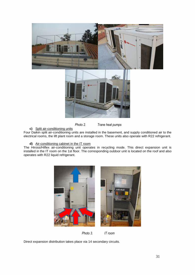
31
Photo 2. Trane heat pumps c) Split air-conditioning units
Four Daikin split air-conditioning units are installed in the basement, and supply conditioned air to the electrical rooms, the lift plant room and a storage room. These units also operate with R22 refrigerant.
d) Air-conditioning cabinet in the IT room The Hiross/Hiflex air-conditioning unit operates in recycling mode. This direct expansion unit is installed in the IT room on the 1st floor. The corresponding outdoor unit is located on the roof and also operates with R22 liquid refrigerant.
Photo 3. IT room
Direct expansion distribution takes place via 14 secondary circuits.

32
The following table gives an overview of the principal characteristics of the technical installations currently in place:
LIST OF THE MECHANICAL EQUIPMENT
ITEM DESCRIPTION MAKE TYPE LOCATION NOTES
4.1.1 Outdoor Unit
VRV--1 Daikin RSXY10K7W1 Roof Inverter, Freon R22
4.1.2 Outdoor Unit
VRV--2 Daikin RSXY10K7W1 Roof Inverter, Freon R22
4.1.3 Outdoor Unit
VRV--3 Daikin RSXY10K7W1 Roof Inverter, Freon R22
4.1.4 Outdoor Unit
VRV--4 Daikin RSXY10K7W1 Roof Inverter, Freon R22
4.1.5 Outdoor Unit
VRV--5 Daikin RSXY10K7W1 Roof Inverter, Freon R22
4.1.6 Outdoor Unit
VRV--6 Daikin RSXY10K7W1 Roof Inverter, Freon R22
4.1.7 Outdoor Unit
VRV--7 Daikin RSXY10K7W1 Roof Inverter, Freon R22
4.1.8 Outdoor Unit
VRV--8 Daikin RSXY10K7W1 Roof Inverter, Freon R22
4.1.9 Outdoor Unit
VRV--9 Daikin RSXY10K7W1 Roof Inverter, Freon R22
4.1.10 Outdoor Unit
VRV--10 Daikin RSXY5K7W1 Roof Inverter, Freon R22
4.2.1 Air Handling Unit AHU-1
Trane CCEA3-SE-3 Basement
Supplies conditioned fresh air to the
communal area on the ground floor
4.2.2 Air Handling Unit AHU-2
Trane CCEA3-SE-1.5 Basement Supplies conditioned
fresh air to the offices on the ground floor
4.2.3 Air Handling Unit AHU-3
Trane CCEA3-SE-1.5 Basement Supplies conditioned
fresh air to the 1st and 2nd floors
4.3.1 Split Air-
Conditioning Unit
Daikin FT603DB7RY45D Basement Cooling only, installed
in electrical panels room, Freon R22
4.3.2 Split Air-
Conditioning Unit
Daikin FT603DB7RY45D Basement Cooling only, installed
in electrical panels room, Freon R22
4.3.3 Split Air-
Conditioning Unit
Daikin FTE32BVRE32B7V1 Basement Cooling only, installed
in lift plant room, Freon R22
4.3.4 Split Air-
Conditioning Unit
Daikin FTY453DB7RY45D Basement Heat pump only,
installed in storage room, Freon R22
4.4.1
Close-control Air-
Conditioning Unit
Hiross 4LOALAC17 1st floor - IT room
Freon R22, condensing unit on roof

33
Vertical distribution takes place via a copper pipe that passes through hoppers. This system shall be retained so as to avoid piercing the entire building.
Photo 4. Horizontal/vertical distribution Power to the equipment installed on the roof is supplied via an outdoor switchboard, which is situated next to the heat pumps.
Photo 5. Retained electrical distribution Power to the indoor fan coil units is supplied via distribution switchboards on the various floors.
Photo 6. Fan coil units mounted on the floor and on a false ceiling

34
Photo 7. A module for regulating the fan coil units The production and distribution units are regulated by modules situated in the entrance hall on the ground floor. Balustrades on the roof
Photo 8. Balustrades

35
ANNEXE II: Specific Health & Safety Plan (SHSP)
SPECIFIC HEALTH & SAFETY PLAN
COMPANY:
ADDRESS:
Contact person:
Telephone:
Fax:
Number of establishment authorisation.
VAT number:
Trade:
Name & address of the agent in Luxembourg (foreign company):
Brief description of the work:
Are you intervening as a subcontractor? YES NO
If YES, for which company?

36
CONTENTS A GENERAL INFORMATION
1. Implementing rules 2. Safety officers in the tenderer’s company 3. Means required by the company 4. Materials & products used 5. Information and training of the personnel
B HEALTH AND SAFETY MEASURES
1. Site installation 2. Medical monitoring of the personnel
C RISK ANALYSES
1. Risks associated with performing the work 2. Risks associated with the organisation of the construction site
D FIRST AID MEASURES

37
1. Implementing rules Foreseen work start date: Foreseen duration of work: Working hours Work at night / weekend: YES NO Foreseen workforce (peak workforce): Do you employ temporary personnel? YES NO If YES, you must ensure that the personnel is able to competently perform the work that they are assigned. Name: ………………………… Position: ………………………. Signature: ………………………. Mandatory list of personnel (including temporary staff) & social security numbers:
Position Name Personnel number:
Number of parking spaces needed
for your construction vehicles: Do you subcontract certain services? YES NO

38
If YES, which? To whom? Name of subcontractor & contact details
2. Safety officers in the tenderer's company
Name of the designated worker: Tel. / Mobile No.: Fax No: Name of the Safety Officer: Tel. / Mobile No.: Fax No: Name of the Site Supervisor: Tel. / Mobile No.: Fax No:
Role: - to respect and ensure respect of the safety rules and instructions; - to ensure that they have received the necessary means to prevent work-related accidents, as defined either in the SHSP or by the current regulations and laws in the country where the work is being performed.
3. Means required by the company
Is electricity required to perform your operations?
YES NO If YES, provided by whom?

39
What current rating (amps) do you require? Do you need three-phase current (380 V)?
YES NO How many connections do you need?
Do you require a water supply?
YES NO
If YES, provided by whom?
Do you require additional elements on the construction site to perform your work?
YES NO
Which:
List of site equipment and machinery brought to the construction site: What type?
If you use lifting means, please provide us the acceptance and/or inspection certificate(s).
4) Materials & products used
Which types of materials (non-hazardous) will you be using on the construction site?
Do you use hazardous products?
YES NO If YES, what are they?
Flammable Oxidising Toxic Harmful Corrosive Irritant Explosive Dangerous for the environment
The material safety data sheets of all hazardous products, notably the chemical products used, must be included in the SHSP. The products used on the construction site must be labelled in accordance with current European Directives.

40
5. Information and training of the personnel The Site Supervisor shall inform all personnel working on the construction site (including temporary personnel) of the work-related safety regulations and instructions applicable at the site and the specific hazards to which they may be exposed:
- the risks involved and the use of the equipment shall be explained by company managers; - the Site Supervisor is called upon to ensure the safety instructions are respected; - personnel called upon to operate site machinery shall be authorised to do so.
Names of the individuals designated to operate machinery:
Name Machine Permits
YES NO

41
B. HEALTH AND SAFETY MEASURES 1. Site installation What equipment do you intend to bring to the construction site?
YES NO NUMBER If NO, made available by?
Site office
Canteen
Lockers
Sanitary installations
WC
Site telephone / Mobile
Waste container
Do you intend to occupy part of the building already built?
YES NO If YES, which part? For what purpose?
2. Medical monitoring of the personnel
- With which medical monitoring organisation are you affiliated?
- -

42
C. RISK ANALYSES
1. Risks associated with performing the work
WORK PHASE Operations
MEANS USED Foreseeable RISKS SAFETY MEASURES ADOPTED
What is being done: Description of the tasks
How it is being done? With which means?
Risks for company employees and for other contractors
How to avoid and protect oneself from risks?

43
WORK PHASE
Operations
MEANS USED
Foreseeable RISKS
SAFETY MEASURES ADOPTED
What is being done:
Description of the tasks
How it is being done? With which means?
Risks for company employees and for other
contractors
How to avoid and protect oneself from risks?

44
2. Risks associated with the organisation of the construction site
WORK PHASE Operations
MEANS USED Foreseeable RISKS SAFETY MEASURES ADOPTED
Equipment deliveries:
Unloading means:
Storage of non-hazardous materials:
Storage of hazardous materials:
Storage and disposal of waste:

45
D. FIRST AID MEASURES
A regulatory first-aid kit must be available at all times on the construction site. Name of your company's first-aider on the construction site:
List of medical equipment on the construction site:
YES NO
- First-aid kit
- Stretcher
- Other equipment*
*Which?
Situation on the construction site:
The instructions to be followed in the event of an accident shall be displayed in the construction camp installations. If an accident does take place, please send a copy of the accident declaration to the European Parliament and insert another copy in the safety log present on the construction site.
Date: Place: Name: Stamp + Signature: