compass series cooling towers - bac...
TRANSCRIPT

Compass Series
Compass Series Cooling TowersRIGGING & ASSEMBLY INSTRUCTIONS

Table of ContentsRIGGING & ASSEMBLY INSTRUCTIONS » Compass Series Cooling Towers
1 Introduction
2 Unit Rigging & Assembly
3 Optional Accessories Installation
1 Safety
1 Shipping
1 Pre-Rigging Checks
2 Unit Weights
2 Anchoring
2 Cold Weather Operation
2 Location
2 Warranties
2 Unit Operation
3 Rigging
3 Fan Guard Installation
4 Two-Piece Fan Guard
5 Side Outlet / Equalizer Depressed Sump Box Installation
6 Heaters and Control Components
7 Ladders / Safety Cages / Handrails Installation
Note:
1. Compass Cooling Towers should be rigged and assembled as outlined in this bulletin. These procedures should be thoroughly reviewed prior to the actual
rigging and assembly of the equipment to acquaint all personnel with procedures to be followed and to assure that all necessary equipment will be available
beforehand.
2. Be sure to have a copy of the certified drawing available for reference. If you do not have a copy of this drawing, or if you need additional information about
this unit, contact your local BAC Representative.

Compass Series Cooling Towers
Introduction
SafetyAdequate precautions appropriate for the installation and location of these products should be taken to safeguard the equipment and the premises from damage and the public from possible injury. The procedures in this manual must be thoroughly reviewed prior to rigging and assembly. Read all dangers, warnings, cautions, and notes detailed in the margins. When the fan speed of the unit is to be changed from the factory set speed, including the use of a variable speed device, steps must be taken to avoid operating at or near the fan’s “critical speed” which could result in fan failure and possible injury or damage. Consult with your local BAC Representative on any such applications.
ShippingModels CPSC-0716-06*, CPSC-0716- 07*, CPSC-0817-07*, CPSC-0817-08* and CPSC-1020-07* are shipped factory assembled or as knockdown units. Models CPSC-1020-08*, CPSC-1020-09*, CPSC-1222-08*, CPSC-1222-09*, CPSC-1222-10*, CPSC-1222-12*, CPSC-1222-14*, CPSC-1424-12*and CPSC-1424-14* are shipped knockdown. For the dimensions and weights of a specific unit or section, refer to the certified drawings or consult with your local BAC Representative.
Pre-Rigging Checks When the unit is delivered to the jobsite, it should be checked thoroughly to ensure all required items have been received and are free of any shipping damage prior to signing the bill of lading.
The following parts should be inspected:
� Sheaves and Belts
� Bearing Supports
� Fan Motor(s)
� Fan(s) and Fan Shaft(s)
� Float Valve Assembly(s)
� Water Distribution System
� Combined Inlet Shields
� Cold Water Basin Accessories
� Interior Surfaces
� Exterior Surfaces
� Water Outlet Strainer
� Fill
� Miscellaneous Items: All bolts, nuts, washers, and sealer tape required to assemble sections or component parts are furnished by BAC and shipped with the unit.
W W W . B A L T I M O R E A I R C O I L . C O M . A U
1M A R 9 0 1 - 0
WARNING: Failure to use lifting provisions can result in a dropped load causing severe injury, death, and/or property damage. Lifts must be performed by qualified riggers following BAC published Rigging Instructions, and generally accepted lifting practices. The use of a supplemental safety sling may also be required if the lift circumstances warrant its use, as determined by the rigging contractor.
CAUTION: Only personnel qualified to do so should undertake operation, maintenance, and repair of this equipment. Proper care, procedures, and tools must be used in handling, lifting, installing, operating, maintaining, and repairing this equipment to prevent personal injury and/or property damage.
Unit Weights
Before rigging any unit, the weight of each section should be verified from the unit certified drawing. Some accessories add additional weight as shown on the respective accessory drawings.
Anchoring
19mm diameter holes are provided in the bottom flange of the basin section for bolting the unit to the support beams. Refer to the suggested support location drawing included in the submittal for location and quantity of the mounting holes. The unit must be level for proper operation. Anchor bolts must be provided by others.
Cold Weather Operation These products must be protected by mechanical and operational methods against damage and/or reduced effectiveness due to possible freeze-up. Please refer to the Series Compass Operation & Maintenance Manual, or contact your local BAC Representative for recommended cold weather operation strategies.
LocationAll evaporative cooling equipment must be located to ensure an adequate supply of fresh air to the unit air intakes. When units are located adjacent to walls or in enclosures, care must be taken to ensure the warm, saturated, discharge air is not deflected and recirculated back to the air intakes. Each unit should be located and positioned to prevent the introduction of discharge air into the ventilation system of any building. For detailed recommendations on BAC equipment layout, please contact your local Distributor.
WarrantiesPlease refer to the Limitation of Warranties (located in the submittal package) applicable to and in effect at the time of the sale/purchase of these products.
Unit OperationPrior to start-up and unit operation, refer to the Series Compass Operation & Maintenance Manual shipped with the unit.
ATTENTION: Before an actual lift is undertaken, ensure no water, snow, ice, or debris has collected in the basin or elsewhere in the unit. Such accumulations will add substantially to the equipment’s lifting weight.
NOTE: Each unit must be located and positioned to prevent the introduction of discharge air into the ventilation systems of the building on which the unit is located and of adjacent buildings.
W W W . B A L T I M O R E A I R C O I L . C O M . A U
2M A R 9 0 1 - 0

Compass Series Cooling Towers
Unit Rigging & Assembly
Figure 1.Unit Rigging & Assembly
NOTE: Using (4)lifting lugs to fix the tower on the truck.
Warning: Failure to use designated lifting points can result in a dropped load causing severe injury, death, and/or property damage. Lifts must be performed by qualified riggers following BAC published Rigging Instructions and generally accepted lifting practices. The use of supplemental safety slings may also be required if the lift circumstances warrant its use, as determined by the rigging contractor.
RiggingIn the event of extended lifts or where hazards exist, the lifting devices should be used in conjunction with safety slings placed under the unit.
Table 2. Number of Fan Guard Pieces
Fan Guard InstallationDue to height limitations on truck shipments, the fan guard of these models may ship unmounted. Refer to Table 2 for the number of fan guard pieces Compass Cooling Towers will have.
Model Number Number of Fan Guard Pieces
CPSC-0716-06* 2CPSC-0716-07* 2CPSC-0817-07* 2CPSC-0817-08* 2CPSC-1020-07* 2
Model NumberDimensions(For Each Section)
Min.H Min. WCPSC-0716-06* 4100mm 2417mmCPSC-0716-07* 4500mm 2417mmCPSC-0817-07* 4500mm 2722mmCPSC-0817-08* 5000mm 2722mmCPSC-1020-07* 5200mm 3388mm
Table 1. Minimum Vertical Dimension and Spreader Bar Length
Lifting Lugs
Safety Slings
Min. WSpreader Bar
Lifting Cable
Min. H
W W W . B A L T I M O R E A I R C O I L . C O M . A U
3M A R 9 0 1 - 0
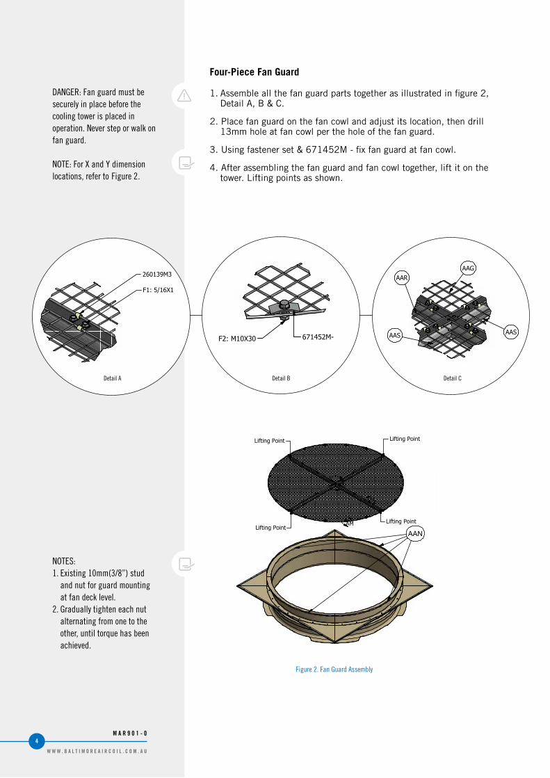
Four-Piece Fan Guard
1. Assemble all the fan guard parts together as illustrated in figure 2, Detail A, B & C.
2. Place fan guard on the fan cowl and adjust its location, then drill 13mm hole at fan cowl per the hole of the fan guard.
3. Using fastener set & 671452M - fix fan guard at fan cowl.
4. After assembling the fan guard and fan cowl together, lift it on the tower. Lifting points as shown.
Figure 2. Fan Guard Assembly
DANGER: Fan guard must be securely in place before the cooling tower is placed in operation. Never step or walk on fan guard.
NOTE: For X and Y dimension locations, refer to Figure 2.
NOTES:1. Existing 10mm(3/8”) stud
and nut for guard mounting at fan deck level.
2. Gradually tighten each nut alternating from one to the other, until torque has been achieved.
DETAIL AL DETAIL AM
DETAIL AN
AL
AM
AN
Page:Drawing Description:
© 2014 Baltimore Aircoil Company
FAN GUARD (EU) ASSEMBLY
Baltimore Aircoil Company AH7RGAHCPSC02Document Number:
Revision: Date:
Z 5/7/2015
Category:
AH-AIR HANDLING
TYPICAL FASTENING DETAILType Seal Type
F2 STANDARD
Sheet 8 of 8
M10 X 303/8 X 1-1/4
Size ANSIMM
AAS
AAR
AAS
AAG
AAN
NOTES:1. Assemble all the fan guard parts together.2. Place fan guard on the fan cowl and adjust its location, then
drill n13 mm hole at fan cowl per the hole of fan guard;3. Using fastener set & 671452M- fix fan guard at fan cowl;4. After assembling the fan guard and fan cowl together, lift it on the tower. Lifting points ase shown.
F2: M10X30 671452M-
F1: 5/16X1
260139M3
Lifting Point Lifting Point
Lifting PointLifting Point
Detail A Detail B Detail C
W W W . B A L T I M O R E A I R C O I L . C O M . A U
4M A R 9 0 1 - 0

Compass Series Cooling Towers
Optional Accessories Installation
Side Outlet / Equalizer Depressed Sump Box Installation (Optional)The optional side outlet depressed sump box allows a cooling tower water outlet connection to be piped from underneath the unit in four possible directions. The piping connection is a bolt circle designed to fit a face flange with a full-face gasket.
To install the side outlet depressed sump box, follow the steps below:
1. Wipe the edges around the opening inside the cold water basin to remove any dirt or moisture that may have accumulated during shipment.
2. Apply two layers of trapezoidal butyl sealer tape (554009) around the opening in the basin over the centerline of the holes. Do not stretch the sealer tape too thinly or overlap. When it is necessary to splice the sealer tape, be sure to press the two ends together to form a smooth continuous strip. Refer to Figure 3.
3. Insert the sump box assembly into the opening in the cold water basin and attach it to the basin with M10X30bolts or drilling screws (no beam under the sump box) as shown in Detail A. The bolts spacing and screws spacing is 75mm. Fix anti-vortex plate on the centerline of the strainer, facing the inlet side. Please refer to installation instruction for bolt fixation.
4. Place the suction strainer over the opening.
Figure 3. Side Outlet / Equalizer Depressed
Sump Box Installation
Sump Suction Strainer
Anti-Vortex Plate
Cold Water Basin
Side Outlet / Equalizer Depressed Sump Box
Layer of Trapezoidal Butyl Sealer Tape (554009)
2 Layers of Trapezoidal Butyl Sealer Tape
M10*30 Bolt & Flatwasher
Self-Tapping Screws
Lockwasher & M10 Nut
Detail A
W W W . B A L T I M O R E A I R C O I L . C O M . A U
5M A R 9 0 1 - 0
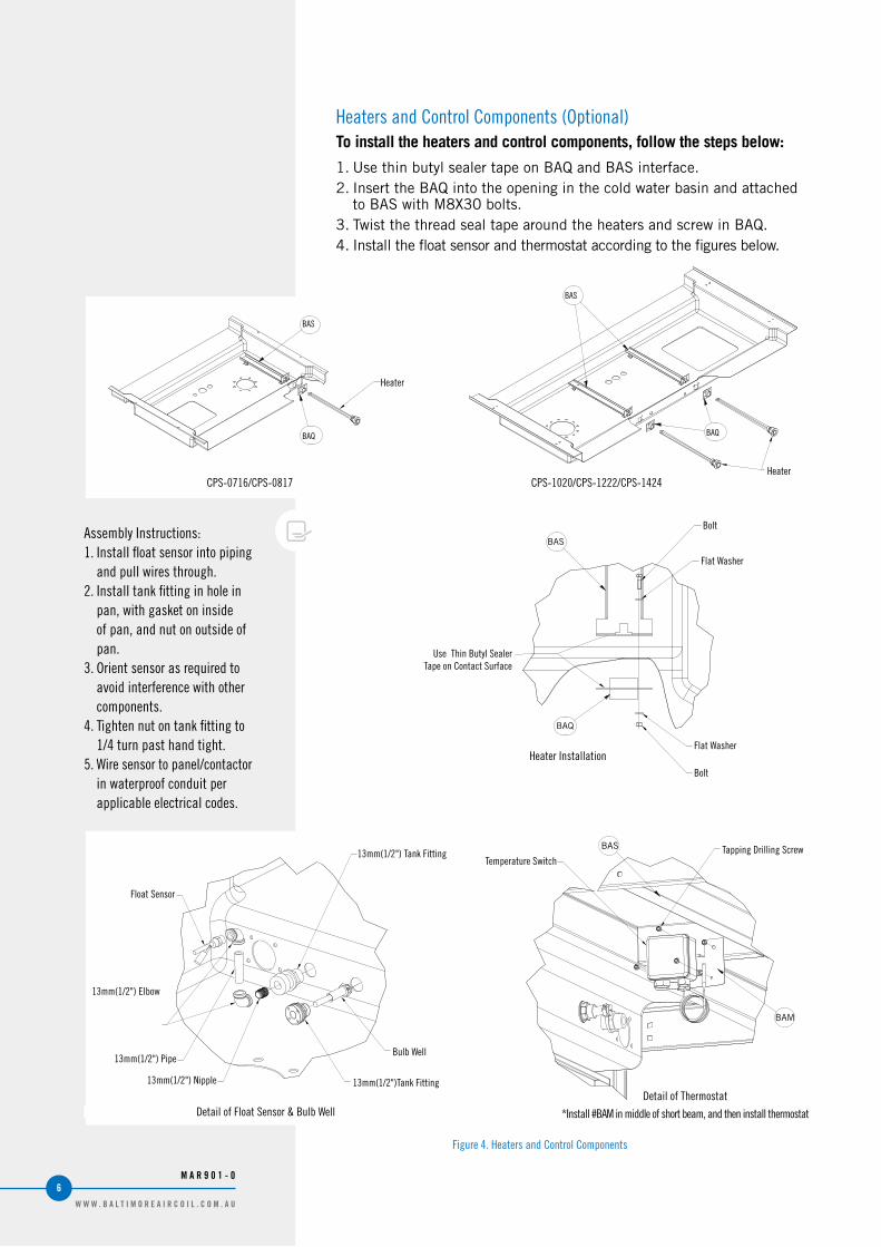
Heaters and Control Components (Optional)To install the heaters and control components, follow the steps below:
1. Use thin butyl sealer tape on BAQ and BAS interface.2. Insert the BAQ into the opening in the cold water basin and attached
to BAS with M8X30 bolts.3. Twist the thread seal tape around the heaters and screw in BAQ.4. Install the float sensor and thermostat according to the figures below.
BAS
BAQ
Assembly Instructions:1. Install float sensor into piping
and pull wires through.2. Install tank fitting in hole in
pan, with gasket on inside of pan, and nut on outside of pan.
3. Orient sensor as required to avoid interference with other components.
4. Tighten nut on tank fitting to 1/4 turn past hand tight.
5. Wire sensor to panel/contactor in waterproof conduit per applicable electrical codes.
Figure 4. Heaters and Control Components
Heater Installation
BAS
BAM
Detail of Thermostat
*Install #BAM in middle of short beam, and then install thermostat
Heater
Bolt
Bolt
Flat Washer
Use Thin Butyl Sealer Tape on Contact Surface
Flat Washer
BAS
BAQ
Heater
BAS
BAQ
Detail of Float Sensor & Bulb Well
13mm(1/2") Tank Fitting Tapping Drilling ScrewTemperature Switch
Float Sensor
13mm(1/2") Elbow
13mm(1/2") Pipe
13mm(1/2") Nipple
Bulb Well
13mm(1/2")Tank Fitting
CPS-1020/CPS-1222/CPS-1424CPS-0716/CPS-0817
W W W . B A L T I M O R E A I R C O I L . C O M . A U
6M A R 9 0 1 - 0

Ladders / Safety Cages / Handrails Installation(Optional)A. To install the ladders, follow the steps below:1. Install the handrail posts PAC & PAD and attached topost or PAL
with four M8 bolts.2. Integrate connect plates (LAD,LAE,LAF,LAG,LAI) with ladder parts
(LAA,LAB,LAH) on the ground.3. Fasten the assembled ladder parts to the tower, PAC and PAD.
局部放大图"A"
局部放大图"B"
紧固件使用M14X30螺栓+2平垫+螺母
LAD
LAA
PAC
LAA
LAB
PAD
PAC
LAC
LAD
LAI
LAF
LAG
LAE
B
C
A
紧固件使用M8X30螺栓+2平垫+螺母
PAA
PAL
HAC
SAD
注意:1.参见紧固件和密封细节的安装说明大纲;2.所有未特殊标注的紧固件都将使用:M10x30 螺栓+ 2平垫+螺母3.96/112 高度的塔没有LAH,LAB,LAI件.
局部放大图"C"
LAH
Figure 5. Ladders Installation
LAD
LAA
PAC
LAA
LAB
PAD
PAC
LAC
LAD
LAI
LAF
LAG
LAE
B
C
A
PAA
PAL
HAC
SAD
注意:1.参见紧固件和密封细节的安装说明大纲;2.所有未特殊标注的紧固件都将使用:M10x30 螺栓+ 2平垫+螺母3.96/112 高度的塔没有LAH,LAB,LAI件.
LAH
Detail A
Fasten With M14x30 Bolt + 2 Plain Washer + Nut
Detail C
Fasten With M8x30 Bolt + 2 Plain Washer + Nut
Detail B
NOTE:1. All of the unspecified fasteners
include M10X30 bolt, 2 flat washer and nut.
2. The 2438mm(96")/2845mm(112") height towers do not use LAH, LAB and LAI.
B. To install the safety cages, follow the steps below:
1. Please refer to the installation diagrams below for different height.2. According to the instruction, assemble the safety cage on the
ground.3. Position the assembled safety cage on the unit and bolt in place.
W W W . B A L T I M O R E A I R C O I L . C O M . A U
7M A R 9 0 1 - 0

7 pcs
7 pcs
7 pcs
7 pcs
7 pcs
LAM
LAL
LAL
LAL
LAL
LAK
LAJ
LAJ
LAJ
LAJ
LAJ
7 pcs
7 pcs
7 pcs
7 pcs
LAM
LAL
LAL
LAL
LAK
LAJ
LAJ
LAJ
LAJ
7 pcs
7 pcs
7 pcs
LAM
LAL
LAL
LAK
LAJ
LAJ
LAJ
7 pcs
7 pcs
LAM
LAL
LAK
LAJ
LAJ
7 pcs
7 pcs
7 pcs
7 pcs
7 pcs
LAM
LAL
LAL
LAL
LAL
LAK
LAJ
LAJ
LAJ
LAJ
LAJ
7 pcs
7 pcs
7 pcs
7 pcs
LAM
LAL
LAL
LAL
LAK
LAJ
LAJ
LAJ
LAJ
7 pcs
7 pcs
7 pcs
LAM
LAL
LAL
LAK
LAJ
LAJ
LAJ
7 pcs
7 pcs
LAM
LAL
LAK
LAJ
LAJ
NOTE: All of the unspecified fasteners include M10X30 bolt, 2 flat washer and nut.
Figure 6. Safety cages Installation
2438mm(96")/2845mm(112")/3251mm(128") Height
3658mm(144")/4064mm(160") Height
4877mm(192") Height
5690mm(224") Height
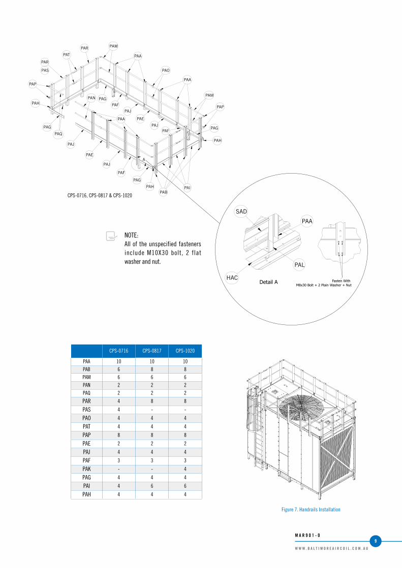
C. To install the handrails, follow the steps below:
1. Install the handrail posts PAA and PAB according to the installation diagrams below.
2. Install the handrail rails PAM, PAN and PAQ, PAO&PAT for joint and PAP for corner.
3. Fasten PAE, PAJ, PAF, PAF, PAK,PAG,PAI and PAH in place.
W W W . B A L T I M O R E A I R C O I L . C O M . A U
8M A R 9 0 1 - 0
A
PAM
PANPAQ
PAA
PAP
PAH
PAG
PAK
PAJ
PAH
PAGPAK
PAFPAJ
PAE
PAGPAK
PAFPAJ
PAH
PAGPAKPAF
PAJPAE
PARPAT
PAR
PAS
PAP
PAOPAM
PAA
PAM
PAA
PAI
PAB
PAQ
PAN
PAH
A
PAT
PAP
PAP
PAA
PAR
PAS
PAR
PAH
PAG
PAJ
PAE
PAJ
PAF
PAG
PAG
PAF
PAJ
PAH
PAGPAF
PAJ
PAE
PAA
PAA
PAO
PAM
PAM
PAIPAB
CPS-0716, CPS-0817 & CPS-1020
NOTE:All of the unspecified fasteners include M10X30 bolt, 2 flat washer and nut.
CPS-0716 CPS-0817 CPS-1020
PAA 10 10 10
PAB 6 8 8
PAM 6 6 6
PAN 2 2 2
PAQ 2 2 2
PAR 4 8 8
PAS 4 - -
PAO 4 4 4
PAT 4 4 4
PAP 8 8 8
PAE 2 2 2
PAJ 4 4 4
PAF 3 3 3
PAK - - 4
PAG 4 4 4
PAI 4 6 6
PAH 4 4 4
A
紧固件使用
M8X30螺栓+2平垫+螺母
PAA
PAL
HAC
SAD
局部放大图"A"
Figure 7. Handrails Installation
PAA
PAL
HAC
SAD
Fasten With M8x30 Bolt + 2 Plain Washer + Nut
Detail A
W W W . B A L T I M O R E A I R C O I L . C O M . A U
9M A R 9 0 1 - 0

COOLING TOWERS
CLOSED CIRCUIT COOLING TOWERS
ICE THERMAL STORAGE
EVAPORATIVE CONDENSERS
HYBRID PRODUCTS
PARTS & SERVICES
w w w . B a l t i m o r e A i r c o i l . c o m . a u
120 Wisemans Ferry Road, Somersby NSW 2250 › Telephone (Australia): 1300.134.622 › Telephone (New Zealand): 0800.225.842